oxygen transport membrane modules for oxyfuel … · 2-lean gas, p o2, sweep) retentate ... •...
TRANSCRIPT

Mitg
lied
der H
elm
holtz
-Gem
eins
chaf
t
Forschungszentrum JülichInstitute of Energy and Climate Research IEK-1
52425 Jülich, Germany
Stefan Baumann
AMPEA WorkshopMaterials for membranes in energy applications: gas separation
membranes, electrolysers and fuel cellsSINTEF, Oslo, NO, Feb 7-8th 2017
Oxygen Transport Membrane Modules forOxyfuel Applications developed in GREEN-CC

2
Coordinator: Dr. Wilhelm A. Meulenberg Forschungszentrum Jülich
Graded Membranes for Energy Efficient New generation Carbon Capture Process
Total Budget: 8.200.000 €Funding: 5.400.000 €Duration: 01.09.2013 - 31.08.2017FP7 project no. 608524
Project facts and figures
www.GREEN-CC.eu
WP1: Membrane
- Materials- Support- Assembly- Modeling
WP2: Catalyst
- Materials- Modeling- Application
WP3: Application oriented testing
- Stability - Slip stream in real PP- Permeation
WP4: Proof-of-concept
- Module design - Membrane assembling- Test facilities design- Module testing
WP5: Process Engineering
- Process Simulations- Scale up rules- Cost estimations

3
Coordinator: Dr. Wilhelm A. Meulenberg Forschungszentrum Jülich
Graded Membranes for Energy Efficient New generation Carbon Capture Process
Total Budget: 8.200.000 €Funding: 5.400.000 €Duration: 01.09.2013 - 31.08.2017FP7 project no. 608524
Outline
www.GREEN-CC.eu
WP5: Process Engineering
- Process Simulations- Scale up rules- Cost estimations

4
4-end membranes for oxyfuel combustion in industrial applications
O2-
e-
feed(Air, pO2, feed)
sweep(O2-lean gas,
pO2, sweep)
retentate(depleted AirpO2, retentate)
permeate(O2-rich gas, pO2, permeate)
j(O2)
Main target: Identifying the energetic and economic benefit of an OTM in all 3 process routes under consideration of realistic boundary conditions
Oxyfuel Power PlantIGCC Oxyfuel Cement

5
Fuel/Coal
Water
Steam
CO 2
H 2O
O 2/H 2O/CO 2
H 2O/CO 2
O 2
Hot flue gas cleaning
Depleted air
Feed-air
850 °C
Process conditionsOxyfuel process - 4-end integration
Flue gas component
concentration
CO2 balance
H2O 25 %
O2 3-5%
SO2
2000 ppm (no gas cleaning)
500 ppm (state-of-the-art HT-cleaning)
50 ppm (state-of-the-art LT-cleaning)
NOx 140 ppm
HCl 30 ppm
CO 10 ppm
Others
(incl. Ash)???

6
Coordinator: Dr. Wilhelm A. Meulenberg Forschungszentrum Jülich
Graded Membranes for Energy Efficient New generation Carbon Capture Process
Total Budget: 8.200.000 €Funding: 5.400.000 €Duration: 01.09.2013 - 31.08.2017FP7 project no. 608524
Project facts and figures
www.GREEN-CC.eu
WP4: Proof-of-concept
- Module design - Membrane assembling- Test facilities design- Module testing
WP5: Process Engineering
- Process Simulations- Scale up rules- Cost estimations

7
Module design and operation
Design and build of a pilot loop for module testingProof of performance (TRL 4)
• Operating temperature 750 – 900 °C• Leakage lower than 2%• Long term tests (1000 h) in a synthetic flue gas stream
Design and build of a proof- of-concept membrane module
• Planar stack with asymmetric membranes • Effective area at least 300 cm2
• 4-end operation
Key issues/activities• Mechanical stress analysis • CFD simulation• Joining techniques for ceramic-ceramic
and ceramic-metal joints
8
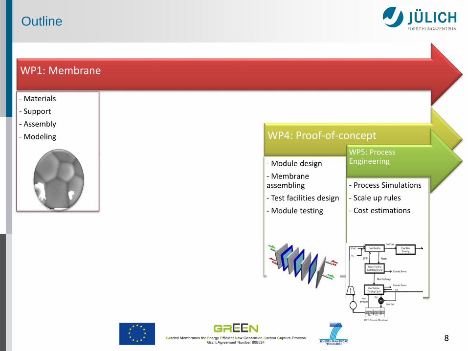
Outline
WP1: Membrane
- Materials- Support- Assembly- Modeling WP4: Proof-of-concept
- Module design - Membrane assembling- Test facilities design- Module testing
WP5: Process Engineering
- Process Simulations- Scale up rules- Cost estimations

9
Oxygen Transport in Mixed Conductors
1. Schulze-Küppers, Dissertation Ruhr-Universität Bochum (2010)
(1)
2. Bouwmeester et al. Fundamentals of Inorganic Membrane Science and Technology(1996)
Zone III Bulk diffusion
Zone II & IV Surface exchange kinetics
Zone V Gas transport in supportI & VI GastransportII & IV Surface ExchangeIII Bulk DiffusionV Gastransport in Support
''
'
2
22 ln
²161
O
O
ei
eiOpp
FRT
Lj ⋅
+⋅
⋅⋅−=
⋅
σσσσ
''
'
2
22 ln
²1621
O
O
ei
ei
c
Opp
FRT
LLj ⋅
+⋅
⋅⋅
+−=
⋅
σσσσ
kDLc
*= Characteristic Thickness
driving force
∇𝑇𝑇,𝑃𝑃𝑥𝑥𝑖𝑖 +𝑥𝑥𝑖𝑖𝑝𝑝𝑔𝑔𝑔𝑔𝑔𝑔
∇𝑝𝑝𝑔𝑔𝑔𝑔𝑔𝑔 = 𝑅𝑅𝑇𝑇��𝑥𝑥𝑖𝑖𝑗𝑗𝑗𝑗��⃗ − 𝑥𝑥𝑗𝑗 𝑗𝑗𝑖𝑖��⃗ �𝑃𝑃𝑔𝑔𝑔𝑔𝑔𝑔𝐷𝐷𝑖𝑖𝑗𝑗
𝑛𝑛
𝑗𝑗=1
− 𝑓𝑓𝑖𝑖𝑖𝑖 𝑅𝑅𝑇𝑇𝑝𝑝𝑔𝑔𝑔𝑔𝑔𝑔
𝑗𝑗𝑖𝑖��⃗
molecular diffusion
Knudsen-Diff. +viscos flow
(2)

10
Selected materials
Single phaseperovskites Dual phase composites
La0.6Sr0.4Co0.2Fe0.8O3-δ(reference)
High performance Asymmetric
membranes developed Good stability in CO2
Limited stability in SO2
Ionic conductor: Doped ceria stabilized zirconia
Electronic conductor: Spinels doped ZnO perovskites
FeCo2O4
Ce0.8Gd0.2O2

11
Ce0.8Gd0.2O2-δ - FeCo2O4 TEM Analysis
3 phases identified:
Ce-Gd-O
Gd-Ce-Fe-Co-O
Fe-Co-O is wrapped in porous O deficient
Fe/Co-O phase (with preferential porosity)
FeOy CoOyRamasamy et al. J Amer Ceram Soc 99 (2016) 349-355
After optimized sintering cycle

12
TF
RL
jpermeance i
pp
O
O
Oσ⋅
⋅⋅==
²161
ln2
2
2
'''
0.8 0.9 1.0 1.1-9.0
-8.5
-8.0
-7.5
-7.0
-6.5
Ea (LSCF58) =138 kJ/mol
Ea (CGO-FCO)= 97 kJ/mol
Ea (CGO-FCO+LSCF-AB)= 66 kJ/mol
log
perm
eanc
e mol
/(cm
2 s)
1000/T (K-1)
CGO-FCO CGO-FCO-LSCF-AB LSCF58
1050 1000 950 900 850 800 750 700 650
Temperature °C
Ramasamy et al. J. Am. Ceram. Soc., 99 [1] 349–355 (2016)
approximate composition of the perovskite phase is 15% Ce on A-site, 25% Co on B-site, i.e. Gd0.85Ce0.15Fe0.75Co0.25O3 (GCFCO)
Ramasamy et al. Ceram Sci Eng Proc, ICACC 2016, accepted manuscript
Ionic conductivity of CGO is rate limiting if surfaces are activated
60 wt% Ce0.8Gd0.2O2-δ - 40 wt% FeCo2O4

13
GCFCO is a pure electronic conductor contributing to ambipolar conductivity
Electronic conductivity still dominant for 20 wt% spinel content
Percolating network present in as low as 10 wt% of spinel content
Electrical conductivity
Ramasamy et al. Ceram Sci Eng Proc, ICACC 2016, accepted manuscript

14
Ramasamy et al. to be submitted
Oxygen permeation rate
CGO-FCO
in wt %
CGO-FCO
in vol %
60:40 54:46
65:35 59:41
70:30 64.5:35.5
75:25 70:30
80:20 76:24
85:15 81.5:18.5
90:10 87.5:12.5
Maximum permeation rate achieved using 15 wt% spinel

15
Performance of selected OTM materialsLSCF vs 85CGO-15FCO
• La0.6Sr0.4Co0.2Fe0.8O3-δ (LSCF) as reference material and ready for scale up• Dual phase composites more stable, but less mature. Selection for scale up
made for 85 wt% Ce0.8Gd0.2O2-δ – 15 wt% FeCo2O4 (CGO-FCO)

16
Requirements for membranes according to transport Model: Thin, defect free membrane layer on a porous support
Tape casting support
(slurry obtaining pore former)
Pre-sintering Support
Screen printingon support
Composite sintering
Tape casting + screen printingPolymer carrier
porous support
Membrane layer
Sequential tape casting
Tape castingMembrane
layer(slurry withoutpore former)
Tape castingSupport
(slurry containingpore former)
Co-firingMembrane layer +
support
Sequential Tape Casing

17
Membrane Development Ce0.8Gd0.2O2-δ - FeCo2O4
Activation layer: 5 µmMembrane layer: 14 µmSupport porosity: 41 %Thickness ~ 700 µm
Activation layer: 6 µmThickness ~ 1000 µm Surface exchange limited!!!

18
Tape casting
Tape casting/lamination/ milling
Tape casting
Scale up of LSCF membranes

19
Component 7 x 10 cm2
Masks for milling process tape casting in larger scale Closing of porous edges
Scale upLSCF

20
FP7 project no. 608524
Acknowledgement
Thank You forYour aTTenTion