p full pg 1 5 10 · future design controls. 2 ump4191a. ump4191a 3 contents chapter 1 overview...
TRANSCRIPT

User's Manual
P41 / P91Auto-Tune Fuzzy / PIDProfiling Controller
P41 / P91Auto-Tune Fuzzy / PIDProfiling Controller LR
LISTED
U R RoHS

Warning Symbol
Use the Manual
This Symbol calls attention to an operating procedure, practice, or thelike, which, if not correctly performed or adhered to, could result inpersonal injury or damage to or destruction of part or all of theproduct and system. Do not proceed beyond a warning symbol untilthe indicated conditions are fully understood and met.
Installers
System Designer
User
Read Chapter 1, 2
Read All Chapters
Read Chapters 3, 4
NOTE:
It is strongly recommended that an independent LIMIT CONTROLlike the FDC L91 be incorporated into the process to shut downthe equipment at a preset process condition in order to preventpossible damage to product and/or the system.
Information in this user's manual is subject to change without notice.
Copyright January 2009, Future Design Controls, all rights reserved.No part of this publication may be reproduced, transmitted,transcribed or stored in a retrieval system, or translated into anylanguage in any form by any means without the written permission ofFuture Design Controls.
UMP4191A2

3UMP4191A
Contents
Chapter 1 Overview ----------- 5Chapter 1 Overview ----------- 5
Page No
Chapter 2 Installation -------- 32Chapter 2 Installation -------- 32
Chapter 3 Configuration ---- 42Chapter 3 Configuration ---- 42
3-1 Password---------------------- 423-2 Signal Input ------------------ 423-3 Event Input ------------------- 433-4 Control Outputs ------------- 443-5 Alarms ------------------------- 493-6 Configure Home Page ----- 533-7 User Calibration ------------- 533-8 Digital Filter ------------------- 543-9 Failure Transfer -------------- 563-10 Auto-tuning ----------------- 573-11 Manual tuning ------------- 583-12 Manual Mode -------------- 603-13 Data Communication ---- 603-14 Retransmission ------------ 613-15 Output Scaling ------------- 62
Chapter 4 Profiler Operation -- 63Chapter 4 Profiler Operation -- 63
Chapter 5 Specifications ------ 77Chapter 5 Specifications
Page No
Appendix A-1 --------------------- 83Appendix A-1
Appendix A-2 --------------------- 44Appendix A-2
1-1 General ------------------------- 51-2 Ordering Code ---------------- 91-3 Programming Port ---- ------ 111-4 Keys and Displays ------------121-5 Key Operation Flowchart---151-6 Parameter Descriptions ----17
-
2-1 Unpacking -------------------- 322-2 Mounting --------------------- 322-3 Wiring precautions --------- 342-4 Power Wiring ---------------- 362-5 Sensor Input Wiring -------- 362-6 Control Output Wiring ----- 372-7 Alarm /Event Output Wiring 392-8 Event Input Wiring ---------- 392-9 Retransmit Output Wiring -- 392-10 Data Communication ---- 40
4-1 What is a Setpoint Profiler -----4-2 Segment Connections --------4-3 Profiler Modes --------------------4-4 Running, Holding and
Aborting a Profile ----------------4-5 Viewing and Modifying
Profile Progress -------------------4-6 Start ---------------------------------4-7 HoldBack --------------------------4-8 Power Failure --------------------- 694-9 Configuring the Profiler --------4-10 Viewing and Creating
a Profile --------------------------4-11 Event Outputs and PID
Selection ------------------------
636464
65
666667
71
71
76
4 UMP4191A
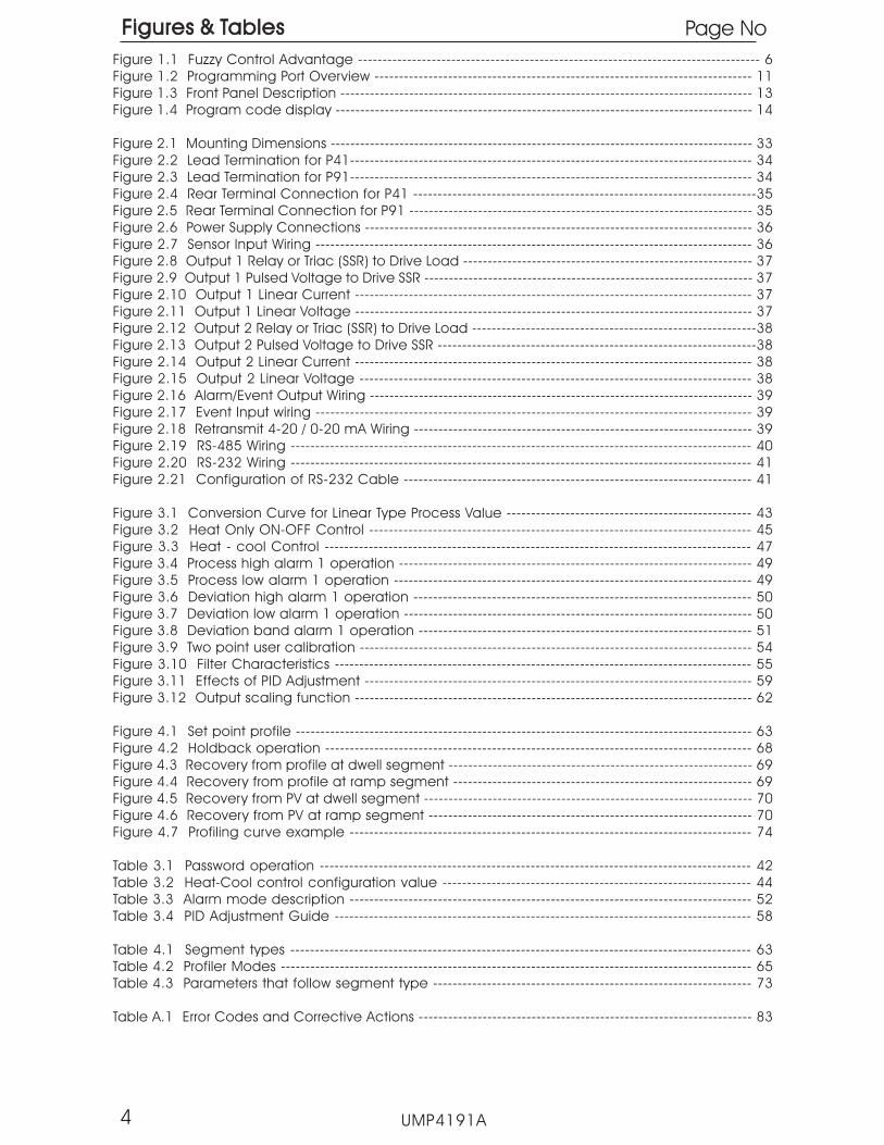
Figure 1.1 Fuzzy Control Advantage ---------------------------------------------------------------------------------- 6Figure 1.2 Programming Port Overview ----------------------------------------------------------------------------- 11Figure 1.3 Front Panel Description ------------------------------------------------------------------------------------ 13Figure 1.4 Program code display ------------------------------------------------------------------------------------- 14
Figure 2.1 Mounting Dimensions -------------------------------------------------------------------------------------- 33Figure 2.2 Lead Termination for P41---------------------------------------------------------------------------------- 34Figure 2.3 Lead Termination for P91---------------------------------------------------------------------------------- 34Figure 2.4 Rear Terminal Connection for P41 ----------------------------------------------------------------------35Figure 2.5 Rear Terminal Connection for P91 ---------------------------------------------------------------------- 35Figure 2.6 Power Supply Connections ------------------------------------------------------------------------------- 36Figure 2.7 Sensor Input Wiring ----------------------------------------------------------------------------------------- 36Figure 2.8 Output 1 Relay or Triac (SSR) to Drive Load ----------------------------------------------------------- 37Figure 2.9 Output 1 Pulsed Voltage to Drive SSR ------------------------------------------------------------------- 37Figure 2.10 Output 1 Linear Current --------------------------------------------------------------------------------- 37Figure 2.11 Output 1 Linear Voltage --------------------------------------------------------------------------------- 37Figure 2.12 Output 2 Relay or Triac (SSR) to Drive Load ----------------------------------------------------------38Figure 2.13 Output 2 Pulsed Voltage to Drive SSR -----------------------------------------------------------------38Figure 2.14 Output 2 Linear Current --------------------------------------------------------------------------------- 38Figure 2.15 Output 2 Linear Voltage -------------------------------------------------------------------------------- 38Figure 2.16 Alarm/Event Output Wiring ------------------------------------------------------------------------------ 39Figure 2.17 Event Input wiring ----------------------------------------------------------------------------------------- 39Figure 2.18 Retransmit 4-20 / 0-20 mA Wiring --------------------------------------------------------------------- 39Figure 2.19 RS-485 Wiring ---------------------------------------------------------------------------------------------- 40Figure 2.20 RS-232 Wiring ---------------------------------------------------------------------------------------------- 41Figure 2.21 Configuration of RS-232 Cable ----------------------------------------------------------------------- 41
Figure 3.1 Conversion Curve for Linear Type Process Value -------------------------------------------------- 43Figure 3.2 Heat Only ON-OFF Control ------------------------------------------------------------------------------ 45Figure 3.3 Heat - cool Control --------------------------------------------------------------------------------------- 47Figure 3.4 Process high alarm 1 operation ------------------------------------------------------------------------ 49Figure 3.5 Process low alarm 1 operation ------------------------------------------------------------------------- 49Figure 3.6 Deviation high alarm 1 operation --------------------------------------------------------------------- 50Figure 3.7 Deviation low alarm 1 operation ----------------------------------------------------------------------- 50Figure 3.8 Deviation band alarm 1 operation -------------------------------------------------------------------- 51Figure 3.9 Two point user calibration -------------------------------------------------------------------------------- 54Figure 3.10 Filter Characteristics ------------------------------------------------------------------------------------- 55Figure 3.11 Effects of PID Adjustment ------------------------------------------------------------------------------- 59Figure 3.12 Output scaling function --------------------------------------------------------------------------------- 62
Figure 4.1 Set point profile --------------------------------------------------------------------------------------------- 63Figure 4.2 Holdback operation --------------------------------------------------------------------------------------- 68Figure 4.3 Recovery from profile at dwell segment -------------------------------------------------------------- 69Figure 4.4 Recovery from profile at ramp segment ------------------------------------------------------------- 69Figure 4.5 Recovery from PV at dwell segment ------------------------------------------------------------------- 70Figure 4.6 Recovery from PV at ramp segment ------------------------------------------------------------------ 70Figure 4.7 Profiling curve example ---------------------------------------------------------------------------------- 74
Table 3.1 Password operation ---------------------------------------------------------------------------------------- 42Table 3.2 Heat-Cool control configuration value --------------------------------------------------------------- 44Table 3.3 Alarm mode description ---------------------------------------------------------------------------------- 52Table 3.4 PID Adjustment Guide ------------------------------------------------------------------------------------- 58
Table 4.1 Segment types ---------------------------------------------------------------------------------------------- 63Table 4.2 Profiler Modes ------------------------------------------------------------------------------------------------ 65Table 4.3 Parameters that follow segment type ----------------------------------------------------------------- 73
Table A.1 Error Codes and Corrective Actions -------------------------------------------------------------------- 83
Figures & TablesFigures & Tables Page No

Chapter 1 OverviewChapter 1 Overview
1-1 General1-1 General
The Fuzzy Logic plus PID microprocessor-based profiling controller series,incorporate two bright, easy to read 4-digit LED displays indicatingprocess value and set point value. The Fuzzy Logic technology enablesa process to reach a predetermined set point in the shortest time, withminimum overshoot during power-up or external load disturbance.
The P91 is a 1/16 DIN size panel mount profiling controller. It can also beused for rail mount by adding a rail mount kit. The P41 is a 1/4 DIN sizepanel mount controller. These units are powered by standard90-250Vac or optional 11-26Vdc supply, incorporating a 2 amp. controlrelay output as standard. The second output can be used as a coolingcontrol output, an event output or an alarm. Both outputs can supporttriac, logic output, linear current or linear voltage.
Both units are fully programmable for PT100 and thermocouple typesJ, K, T, E, B, R, S, N, L, C, P as standard. MA and VDC inputs are optionaland must be specified at time of order. The fast input sampling rate andhigh accuracy 18-bit A to D converter, allow these units to respondquickly in order to control fast processes.
The controller outputs can also be configured as more than just basicheating and/or cooling outputs, these include: up to three alarmoutputs, up to three event outputs and up to two analog retransmissionoutputs.
Digital communications, RS-485 or RS-232, are available as an additionaloption. These options allow the units to be integrated with a supervisorycontrol system and software.
A programming port is available for automatic configurationwithout the need to access the keys on the front panel.
By using proprietary Fuzzy modified PID technology, the control loop willminimize overshoot and undershoot of the process in the shortest timepossible. The following diagram is a comparison of results with andwithout Fuzzy technology.
profiling
5UMP4191A

PID control with properly tuned
PID + Fuzzy control
Warm Up Load Disturbance
Setpoint
Temperature
Time
Figure 1.1Fuzzy ControlAdvantage
Figure 1.1Fuzzy ControlAdvantage
The “P” series can be configured as a single set point controller (staticmode) or a ramp and dwell profiling controller (profile mode). Theprofile mode feature allows the user to program up to 9 profiles ofup to 64 free-format (ramp, dwell, jump or end) segments each. Thetotal segments available for the product is 288 segments.NOTE: Profiles can NOT be linked together.
The profiling controllers contain the following features:
Flexible Program ConfigurationFlexible Program Configuration
Up to 64 segments can be programmed for a single profile. Eachsegment can be configured as a ramp or a dwell (soak) segment, ora jump step defining a repeat number of cycles within the profile andfinally terminated by an end segment. During operation, the user canedit segments of the running profile ro make in process changes.
Maximum Program CapacityMaximum Program Capacity
There are a total of 9 profiles can be defined. Profiles are divided intothree different lengths: profiles 1-4 can be a maximum of 16 segments,profiles 5-7 can be a maximum of 32 segments and profiles 7-9 are64 segments maximum. All profiles begin with segment 0, i.e., profile 1allows for programming of segments 0-15 (for a total of 16 segments)while profile 7 allows programming of segments 0-63 (64 total).
Event InputEvent Input
The event input feature allows the user to select one of eight functions:enter profile run mode, enter profile hold mode, abort profile mode,enter manual mode, perform failure transfer, enter off mode, advanceto the next segment and select second set of PID values.
UMP4191A6
Programmable Event OutputsProgrammable Event Outputs
Up to three relays are configurable for event outputs and the state ofeach output can be defined for each segment and end of profile.
Analog RetransmissionAnalog Retransmission
Output 5 and output 4 (P41 only) of the products can be equippedwith an analog output module. The output can be configured fortransmitting the process value as well as set point value.
High AccuracyHigh AccuracyThe “P” series are manufactured with custom designed ASIC(Application Specific Integrated Circuit ) technology which containsan 18-bit A to D converter for high resolution measurement (true 0.1 Fresolution for thermocouple and PT100 ) and a 15-bit D to A converterfor linear current or voltage control outputs. The ASIC technologyprovides improved operating performance, low cost, enhancedreliability and higher density.
Fast Sampling RateFast Sampling Rate
The sampling rate of the input A to D converter is 5 time/second (5Hz).The fast sampling rate allows the “P” series to control fast processes.
Fuzzy ControlFuzzy Control
The function of fuzzy control is to fine tune and adjust PID parametersbased on the previous response of the process to the controller outputand allow the controller to adapt to various processes. The result is toenable the process to reach a predetermined set point in the shortesttime, with minimum overshoot and undershoot during power-up orexternal load disturbance.
Digital CommunicationDigital Communication
The units can be equipped with an RS-485 or RS-232 interface card toprovide digital communications. When using the RS-485 interface, upto 247 units can be connected together to a host computer.
UMP4191A 7
Programming PortProgramming Port
A programming port is used to connect the unit to aPC for quick configuration.
See Related Products Pg 10

Auto-tune
The auto-tune function allows the user to simplify initial setup for a newsystem. The internal algorithm is provided to obtain an optimal set ofcontrol parameters for the process which can be applied when theprocess is warming up (cold start) or after the process has beenoperating at steady state (warm start) conditions.
Lockout ProtectionLockout Protection
A password can be entered to prevent parameters from beingchanged. If a password is activated, the password must successfullybe set to allow any changes to the unit.
Bumpless TransferBumpless Transfer
Bumpless transfer allows the controller to continue to control by usingits previous output value if the sensor breaks. As a result, the processcan maintain control temporarily as if the sensor was operatingnormally.
Digital FilterDigital Filter
A first order low pass filter with a programmable time constant is usedto improve the stability of the process value. This is particularly useful incertain applications where the process value fluctuates rapidly.
SEL FunctionSEL FunctionThe units provide the ability for user to select parameters which are moreimportant and place these parameters in the home page for quickaccess. There are 8 parameters to choose from which allow the user tobuild their own custom display sequence.
UMP4191A8

Power InputPower Input4: 90 - 250 VAC, 47-63 Hz5: 11 - 26 VAC or VDC,
SELV, Limited Energy
4: 90 - 250 VAC, 47-63 Hz5: 11 - 26 VAC or VDC,
SELV, Limited Energy
0: None1: Relay rated 2A/240VAC2: SSR Driver 5 VDC @ 30 Ma3:
6: Triac output 1A / 240VAC,SSR7: Trans power supply 20 VDC/25 Ma
Isolated8: Trans power supply 12 VDC/40Ma
IsoaltedA: Trans power supply 5 VDC/80 Ma
IsolatedC: SSR Driver 14 VDC @ 40 Ma9: Special order
4 - 20mA / 0 - 20mA Retrans Isolated4: 1 - 5V / 0 - 5V/0 - 10V Retrans Isolated
Output 4 (P41 ONLY)Output 4 (P41 ONLY)
1: Standard InputThermocouple:
J, K, T, E, B, R, S, N, L,C, P
RTD: PT100 DIN, PT100 JISVoltage: 0-60mV
5: 0-10V, 0-1V, 0-5V, 1-5V *6: 0-20/4-20 mA *9: Special Order
1: Standard InputThermocouple:
J, K, T, E, B, R, S, N, L,C, P
RTD: PT100 DIN, PT100 JISVoltage: 0-60mV
5: 0-10V, 0-1V, 0-5V, 1-5V *6: 0-20/4-20 mA *9: Special Order
Signal InputSignal Input
0: None1: Relay rated 2A/240VAC2: SSR Driver 5 VDC @ 30 ma3: 4 - 20mA / 0 - 20mA Isolated4: 1 - 5V / 0 - 5V/0 - 10V Isolated6: Triac output 1A / 240VAC,SSR7: Trans power supply 20 VDC/ 25 ma Isolated8: Trans power supply 12 VDC/40 ma IsolatedA: Trans power supply 5 VDC/80 ma IsolatedC: SSR Driver 14 VDC @ 40 Ma9: Special order
0: None1: Relay rated 2A/240VAC2: SSR Driver 5 VDC @ 30 ma3: 4 - 20mA / 0 - 20mA Isolated4: 1 - 5V / 0 - 5V/0 - 10V Isolated6: Triac output 1A / 240VAC,SSR7: Trans power supply 20 VDC/ 25 ma Isolated8: Trans power supply 12 VDC/40 ma IsolatedA: Trans power supply 5 VDC/80 ma IsolatedC: SSR Driver 14 VDC @ 40 Ma9: Special order
P91-
1-2 Ordering Code1-2 Ordering Code
0: Panel mount IP50 standard1: Panel mount IP65 water resistant
rubber installed2: DIN rail mount with IP50
(for P91 only)3: DIN rail mount with IP65
(for P91 only)
0: Panel mount IP50 standard1: Panel mount IP65 water resistant
rubber installed2: DIN rail mount with IP50
(for P91 only)3: DIN rail mount with IP65
(for P91 only)
Options
0: None1: Relay rated 2A/240VAC2: SSR Driver 5 VDC @ 30 Ma6: Triac output 1A / 240VAC,SSR7: Trans power supply 20 VDC/25 ma Isolated8: Trans power supply 12VDC/40 ma IsolatedA: trans power supply 5VDC/80 ma IsolatedC: SSR Driver 14 VDC @ 40 Ma9: Special order
0: None1: Relay rated 2A/240VAC2: SSR Driver 5 VDC @ 30 Ma6: Triac output 1A / 240VAC,SSR7: Trans power supply 20 VDC/25 ma Isolated8: Trans power supply 12VDC/40 ma IsolatedA: trans power supply 5VDC/80 ma IsolatedC: SSR Driver 14 VDC @ 40 Ma9: Special order
Output 3Output 3
0: None1: Relay rated 2A/240VAC2: SSR Driver 5 VDC @ 30 Ma3: 4 - 20mA / 0 - 20mA Isolated4: 1 - 5V / 0 - 5V/0 - 10V Isolated6: Triac output 1A / 240VAC,SSRC: SSR Driver 14 VDC @ 40 Ma9: Special order
0: None1: Relay rated 2A/240VAC2: SSR Driver 5 VDC @ 30 Ma3: 4 - 20mA / 0 - 20mA Isolated4: 1 - 5V / 0 - 5V/0 - 10V Isolated6: Triac output 1A / 240VAC,SSRC: SSR Driver 14 VDC @ 40 Ma9: Special order
Output 2Output 2
UMP4191A
Output 1Output 1
9
Output 5Output 50: None3:
7: Trans power supply 20 VDC/25maIsolated
8: Trans power supply 12 VDC/40 MaIsolated
A: Trans power supply 5 VDC/80 MaIsolated
D: RS-485 interface IsolatedE: RS-232 interface Isolated
4 - 20mA / 0 - 20mA Retrans Isolated4: 1 - 5V / 0 - 5V/0 - 10V Retrans Isolated
0: None3:
7: Trans power supply 20 VDC/25maIsolated
8: Trans power supply 12 VDC/40 MaIsolated
A: Trans power supply 5 VDC/80 MaIsolated
D: RS-485 interface IsolatedE: RS-232 interface Isolated
4 - 20mA / 0 - 20mA Retrans Isolated4: 1 - 5V / 0 - 5V/0 - 10V Retrans Isolated
P41-
0
* NOTE: Reference ONLY Input solder bridges select type ofinput allowed. These are set as ordered from factory.Input option 1 = T/C, RTD, MV G1-shorted, G2-OpenInput option 5 = VDC-G1-opened, G2-OpenInput option 6 = Ma - G1 Don’t Care, G2-ShortIf an input field change is required CONSULT FACTORY.

OM94-6 = Isolated 1A / 240VAC Triac Output Module ( SSR )OM94-7 = 14V / 40mA SSR Drive ModuleOM98-3 = 4 - 20 mA / 0 - 20 mA Analog Output Module IsolatedOM98-5 = 0 -10V Analog Output Module IsolatedCM94-1 = RS-485 Interface Module for P41 Output 5 IsolatedCM94-2 = RS-232 Interface Module for P41 Output 5 IsolatedCM94-3 = 4-20mA/0-20mA Retrans Module for P41 Output 5 IsolatedCM94-5 = 0-10V Retrans Module for P41 Output 5 IsolatedCM97-1 = RS-485 Interface Module for P91 Output 5 IsolatedCM97-2 = RS-232 Interface Module for P91 Output 5 IsolatedCM97-3 = 4-20mA/0-20mA Retrans Module for P91 Output 5 IsolatedCM97-5 = 0-10V Retrans Module for P91 Output 5 IsolatedDC94-1 = 20V/25mA DC Output Power Supply IsolatedDC94-2 = 12V/40mA DC Output Power Supply IsolatedDC94-3 = 5V/80mA DC Output Power Supply IsolatedDC97-1 = 20V/25mA DC Output Power Supply for P91 Output 5 IsolatedDC97-2 = 12V/40mA DC Output Power Supply for P91 Output 5IsolatedDC97-3 = 5V/80mA DC Output Power Supply for P91 Output 5 IsolatedCC94-1 = RS-232 Interface Cable ( 2M )CC91-1 = Programming Port CableRK91-1 = Rail Mount kit for P91DC21-1 = 20V/25mA DC Output Power Supply for P41 Output 5 IsolatedDC21-2 = 12V/40mA DC Output Power Supply for P41 Output 5 IsolatedDC21-3 = 5V/80mA DC Output Power Supply for P41 Output 5Isolated
Accessories
Related ProductsRelated Products
UMP4191A10
SNA-10A - This is an RS232/RS485 converter used for 3rd party softwaresupporting multi-loop RS-485 serial communications.
SNA-12A This is an RS232/RS485 converter used with the FDC-SetConfiguration software.P/n CC91-1 This is a Configuration cable and must also be used withSNA-12A when using FDC -Set.

1-3 Programming Port1-3 Programming Port
A special connector (CC91-1) is used to connect the programmingport to a PC for automatic configuration. The PC must have FDC-Setinstalled to use the configuration feature via PC.
The programming port is used for automatic setup and testingprocedures only. Do attempt to make any connection to thesepins when the unit is “On-Line” in a running application.
See page 10 for parts needed for using configurator port.
off-line
NOT
UMP4191A 11
FrontPanel
RearTerminal
Access HoleAccess Hole
1
1
3
3
4
4
6
6
Figure 1.2Programming PortOverview
Figure 1.2Programming PortOverview
2
2
5
5
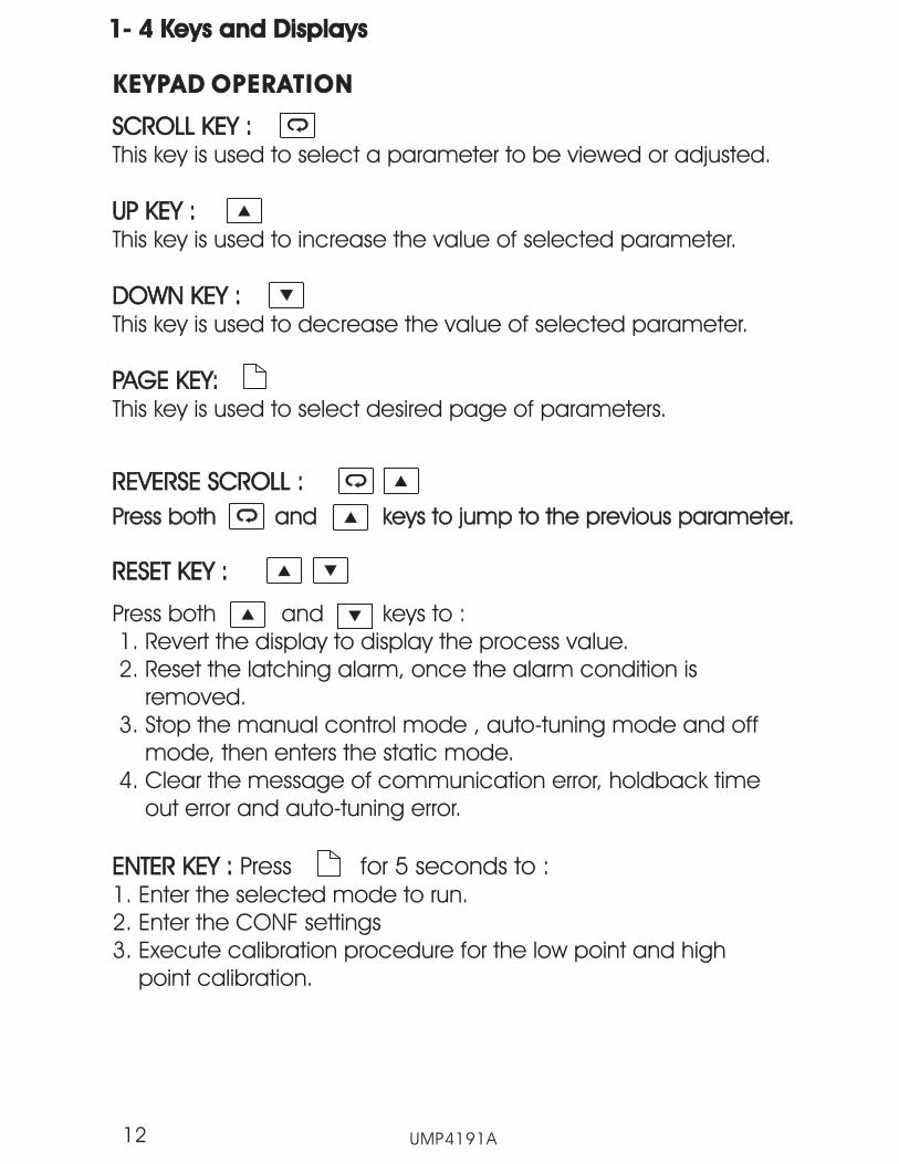
1- 4 Keys and Displays1- 4 Keys and Displays
KEYPAD OPERATIONKEYPAD OPERATION
SCROLL KEY :
UP KEY :
DOWN KEY :
PAGE KEY:
This key is used to select a parameter to be viewed or adjusted.
This key is used to increase the value of selected parameter.
This key is used to decrease the value of selected parameter.
This key is used to select desired page of parameters.
SCROLL KEY :
UP KEY :
DOWN KEY :
PAGE KEY:
Press both and keys to :1. Revert the display to display the process value.2. Reset the latching alarm, once the alarm condition is
removed.3. Stop the manual control mode , auto-tuning mode and off
mode, then enters the static mode.4. Clear the message of communication error, holdback time
out error and auto-tuning error.
ENTER KEY : Press for 5 seconds to :1. Enter the selected mode to run.2. Enter the CONF settings3. Execute calibration procedure for the low point and high
point calibration.
ENTER KEY :
UMP4191A12
REVERSE SCROLL :REVERSE SCROLL :
Press both and keys to jump to the previous parameter.Press both and keys to jump to the previous parameter.
RESET KEY :RESET KEY :
P41
Out3
Out4
Out2
Out1
RUN
HLD
SV
PV
LCLC
LFLF
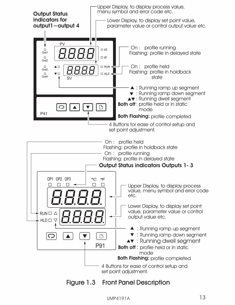
Output Statusindicators foroutput1~output 4
Upper Display, to display process value,menu symbol and error code etc.
Lower Display, to display set point value,parameter value or control output value etc.
4 Buttons for ease of control setup andset point adjustment.
On : profile heldFlashing: profile in holdback
state
On : profile runningFlashing: profile in delayed state
: Running ramp up segment: Running ramp down segment: Running dwell segment: profile held or in static
modeBoth off
Figure 1.3 Front Panel DescriptionFigure 1.3 Front Panel Description
UMP4191A 13
OP1 OP2 OP3
RUN
P91
C F
HLD
4 Buttons for ease of control setup andset point adjustment.
::
Running ramp up segment
Running ramp down segment
profile held or in staticmode
: Running dwell segment:Both off
Upper Display, to display processvalue, menu symbol and error codeetc.
Lower Display, to display set pointvalue, parameter value or controloutput value etc.
Output Status indicators Outputs 1- 3
On : profile heldFlashing: profile in holdback state
On : profile runningFlashing: profile in delayed state
Both Flashing: profile completed
Both Flashing: profile completed

Figure 1.4 Program code displayFigure 1.4 Program code display
The unit will display the program code for 2.5 seconds during power up.The code is the program number followed by the version number. Forthe P41, the program number is 37. The program number for the P91 is38. In the example figure below, the version number is 12.
UMP4191A14
P41
Out3
Out4
Out2
Out1
RUN
HLD
SV
PV
LCLC
LFLF
SEL7
SEL4
DLLT
P2EV
HB
TGSP
RT or RR
P2EV
HB
DLLT
P2EV
HB
SEG
CYCL
SGNO
SGTY
FSP
CYCL
SEG
CYCL
SGNO
SGTY
TGSP
RT or RR
P2EV
HB
( 1-9 )
HBBD
STSP
RMPU
DLLU
SGNO
SGTY
UMP4191A
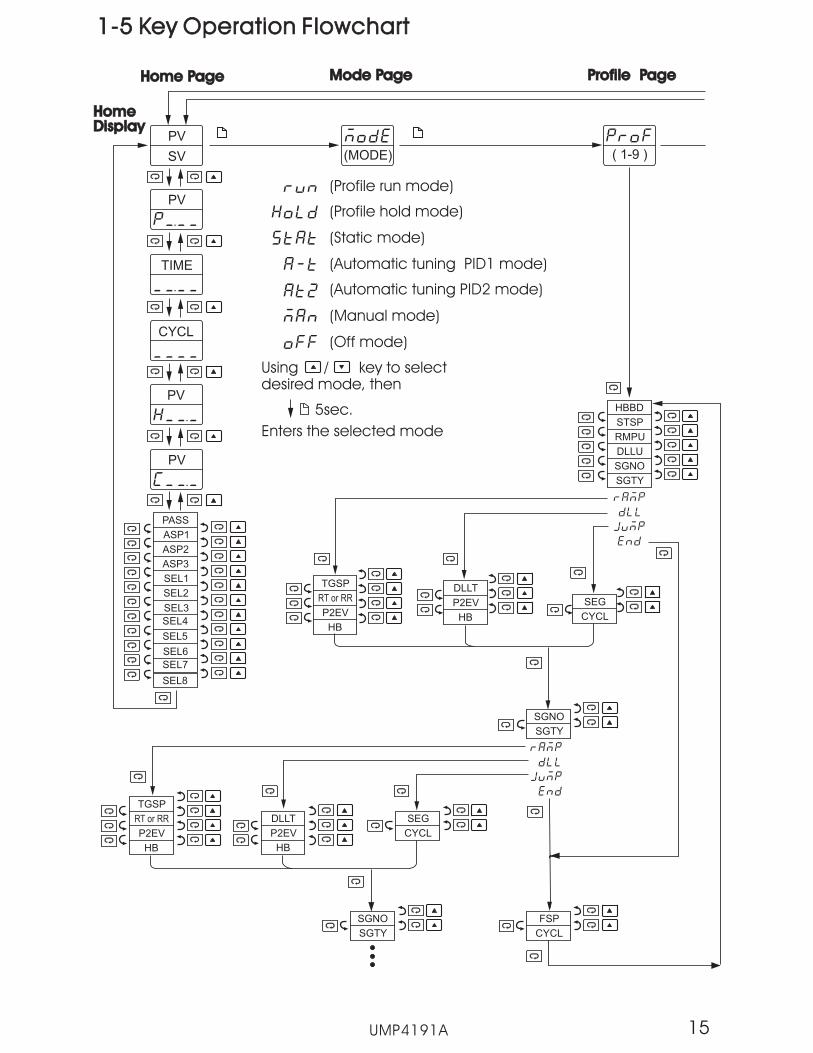
1-5 Key Operation Flowchart1-5 Key Operation Flowchart
ASP1
PASS
ASP2
ASP3
SEL1
SEL3
SEL2
SEL5
SEL6
SEL8
PV
Home PageHome Page Mode PageMode Page
SV
PV
TIME
CYCL
PV
PV
(MODE)
(Profile run mode)
(Profile hold mode)
(Static mode)
(Automatic tuning PID1 mode)
(Manual mode)
(Off mode)
HomeDisplayHomeDisplay
(Automatic tuning PID2 mode)
Using / key to selectdesired mode, then
5sec.
Enters the selected mode
Profile PageProfile Page
15
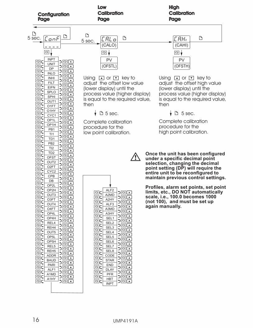
(CALO)
(OFSTL)
PV
Using or key toadjust the offset low value(lower display) until theprocess value (higher display)is equal to the required value,then
(CAHI)
(OFSTH)
PV
Using or key toadjust the offset high value(lower display) until theprocess value (higher display)is equal to the required value,then
5 sec.
Complete calibrationprocedure for thehigh point calibration.
5 sec.
Complete calibrationprocedure for thelow point calibration.
Low
Calibration
Page
Low
Calibration
Page
High
Calibration
Page
High
Calibration
Page
UMP4191A
INPT
UNIT
DP
INLO
SPLO
FILT
O1HY
INHI
O1FT
SPHI
EIFN
CYC1
OP1L
OP1H
OUT2
O2FT
CYC2
PB1
PB2
OUT1
TI1
TI2
TD1
TD2
OFST
CPB
DB
OP2L
OP2H
O3FT
OUT3
OUT4
O4FT
OUT5
REH4
REL4
OP4H
OP4L
OP5L
OP5H
REL5
REH5
ADDR
BAUD
PARI
ALF1
A1MD
A1HY
ConfigurationPageConfigurationPage
ALF2
A2MD
A2HY
ALF3
A3MD
A3HY
STAR
END
DLAY
PFR
HBT
CODE
SEL1
SEL2
SEL3
SEL4
SEL5
SEL6
SEL7
SEL8
INPT
16
5 sec.5 sec.
Once the unit has been configuredunder a specific decimal pointselection, changing the decimalpoint setting (DP) will require theentire unit to be reconfigured tomaintain previous control settings.
Profiles, alarm set points, set pointlimits, etc., DO NOT automaticallyscale, i.e., 100.0 becomes 1000(not 100), and must be set upagain manually.

1-6 Parameter Descriptions1-6 Parameter Descriptions
ParameterNotation
Parameter Description Range DefaultValue
Indicate the currentProfile/Segmentnumber
Time remaining forthe current segment
Low: 1.00 High: 9.63
Low: 00.00 High: 99.59TIME
CYCL cycle remaining forthe current profile
Low: 1 High: 999910000=infinite
Set point for alarm 1 Low: -32768 High: 3276710.0 C(18.0 F)
ASP1
Set point for alarm 210.0 C(18.0 F)
Set point for alarm 310.0 C(18.0 F)
ASP2
ASP3
Password entry 1
SP1Controller (Static mode)Set point value Low: SPLO High: SPHI
25.0 C(77.0 F)
Profile numberSegment number
RegisterAddress
0
Datatype
R/W
1
2
3
5
6
7
R/WPFSG
Low: -32768 High: 32767
Low: -32768 High: 32767
R/W
R/W
R/W
4 Low: 0 High: 9999 R/W
UMP4191A
R/W
R
1.00
PASS
INPT
0
1
2
3
4
5
6
: T type T/C
: E type T/C
: B type T/C
: R type T/C
: S type T/C
: J type T/C
: K type T/C
7
8
11
12
: N type T/C
: L type T/C
: PT 100 ohmsDIN curve
: PT 100 ohmsJIS curve
Input sensorselection
1(0)
9
10
: C type T/C
: P type T/C
R/W8
(T/C = thermocouple)
17
See Note *1

UMP4191A
UNIT
DP
15
16
13
14
: 4 - 20 mA linearcurrent input
: 0 - 20 mA linearcurrent input
: 0 - 1V linearvoltage input
: 0 - 60 mV linearmillivolt input
17
18
19
: 0 - 5V linearvoltage input
: 1 - 5V linearvoltage input
: 0 - 10V linearvoltage input
Input unitselection
0
1
2
: Degree C unit
: Degree F unit
: Process unit
0(1)
Decimal pointselection
0
1
2
3
1
: No decimal point
: 1 decimal digit
: 2 decimal digits
: 3 decimal digits
ParameterNotation
ParameterDescription Range Default
ValueRegisterAddress
Datatype
9
10
R/W
R/W
INPT
Input sensorselection
81(0) R/W
MODE11 Operation mode
0 :Profile run mode
1 :Profile hold mode
2 :Static mode
3 :Automatic tuningPID1 mode
4 : Automatic tuningPID2 mode
6 :Off mode
R/W0
5 :Manual mode
INLO
INHI
Input low scalevalue
Input high scalevalue
-32768
INLO+50
INHI-50
32767
Low:
Low:
High:
High:
-17.8 C( 0 F )
93.3 C(200.0 F)
12
13
R/W
R/W
18
NOTE:Linear Inputsselections13-19MUST beORDERED touse properlySee ordermatrix Page 9
See Note *2on PG 31
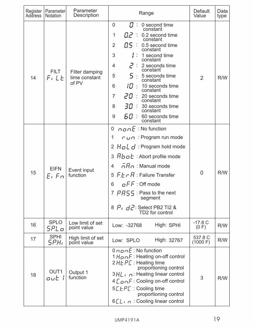
SPLO
SPHI
FILT
OUT1
Low limit of setpoint value
-17.8 C(0 F)
High limit of setpoint value
537.8 C(1000 F)
-32768 High: SPHILow:
SPLO High: 32767Low:
Filter dampingtime constantof PV
0 0 second timeconstant
:
1 0.2 second timeconstant
:
8 30 seconds timeconstant
:
9 60 seconds timeconstant
:
7 20 seconds timeconstant
:
6 10 seconds timeconstant
:
5 5 seconds timeconstant
:
4 2 seconds timeconstant
:
3 1 second timeconstant
:
2 0.5 second timeconstant
:
2
3Output 1function
ParameterNotation
ParameterDescription Range Default
ValueRegisterAddress
Datatype
16
17
14
EIFN15
0 : No function
1 : Heating on-off control
4 : Cooling on-off control
2 : Heating timeproportioning control
3 : Heating linear control
5 : Cooling timeproportioning control
6 : Cooling linear control
0 : No function
1 : Program run mode
2 : Program hold mode
3 : Abort profile mode
7 : Pass to the nextsegment
8 : Select PB2 TI2 &TD2 for control
18
0
UMP4191A
R/W
R/W
R/W
R/W
R/W
Event inputfunction
6 : Off mode
4 : Manual mode
5 : Failure Transfer
19

O1FT
O1HY
CYC1
Output 1 failuretransfer status
Select BPLS ( bumplesstransfer ) or 0.0 ~ 100.0 % tocontinue output 1 controlfunction as the unit fails, orselect OFF (0) or ON (1) forON-OFF control.
0
Output 1 ON-OFFcontrol hysteresis Low: 0.1 High:50.0 C(90.0F)B
0.1C(0.2 F)
Output 1 cycletime
Low: 0.1 High: 90.0 sec. 18.0
Proportionalband value 1
10.0 C(18.0 F)Low: 0 High:
500.0 C(900.0 F)
Integral timevalue 1
Derivative timevalue 1
100
25.0
Low: 0
Low: 0
High: 3600 sec
High: 900.0 sec
OP1L Low limit value foroutput 1
Low: 0 High: 100.0 % 0
OP1H High limit valuefor output 1
Low: 0 High: 120.0 % 100.0
ParameterNotation
ParameterDescription Range Default
ValueRegisterAddress
Datatype
19
20
21
22
23
24
25
26
PB1
TI1
TD1
Proportionalband value 2
10.0 C(18.0 F)Low: 0 High:
500.0 C(900.0 F)
Integral timevalue 2
Derivative timevalue 2
100
25.0
Low: 0
Low: 0
High: 3600 sec
High: 900.0 sec
27
28
29
PB2
TI2
TD2
Offset value forP control (TI=0) Low : 0.0 25.0High : 100.0%30
OFST
31
32
OUT2Output 2 function
0 : No function
1 : Cooling timeproportioning control
2 : Cooling linear control
5 : Event 1 output
333
R/W
R/W
R/W
R/W
R/W
R/W
R/W
R/W
R/W
R/W
R/W
R/W
R/W
Reserved
Reserved
UMP4191A
6 : DC power supplyoutput
20
3 : Alarm 1 output
4 : Reverse alarm 1Output
ParameterNotation
ParameterDescription Range Default
ValueRegisterAddress
Datatype
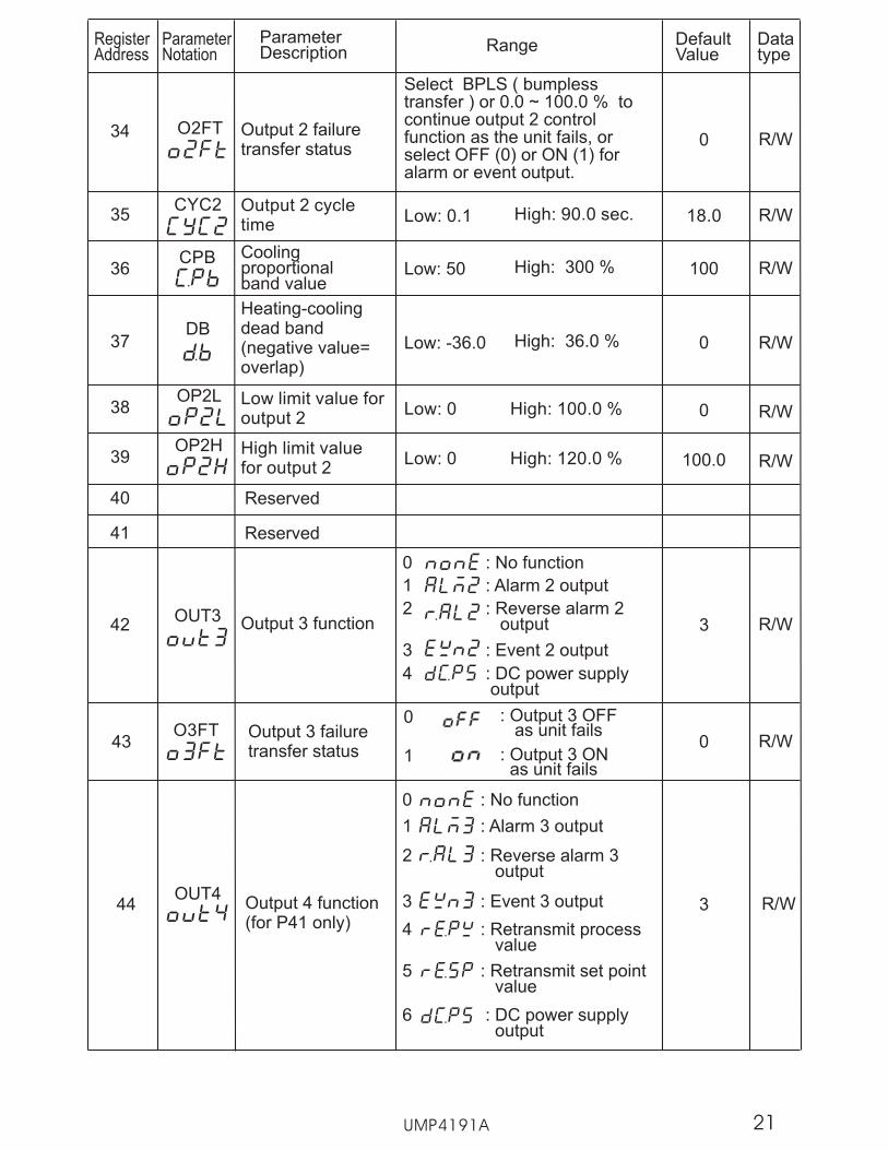
O2FT
Select BPLS ( bumplesstransfer ) or 0.0 ~ 100.0 % tocontinue output 2 controlfunction as the unit fails, orselect OFF (0) or ON (1) foralarm or event output.
Output 2 failuretransfer status
0
Coolingproportionalband value
100Low: 50 High: 300 %
CYC2 Output 2 cycletime
Low: 0.1 High: 90.0 sec. 18.0
CPB
34
35
36
Heating-coolingdead band(negative value=overlap)
0Low: -36.0 High: 36.0 %DB
OP2L Low limit value foroutput 2
Low: 0 High: 100.0 % 0
OP2H High limit valuefor output 2
Low: 0 High: 120.0 % 100.0
37
38
39
40
41
1 : Alarm 2 output
0 : No function
Output 3 functionOUT3342
Output 3 failuretransfer status
043O3FT
0
1 : Output 3 ONas unit fails
: Output 3 OFFas unit fails
UMP4191A
R/W
R/W
R/W
R/W
R/W
R/W
R/W
R/W
Reserved
Reserved
4 : DC power supplyoutput
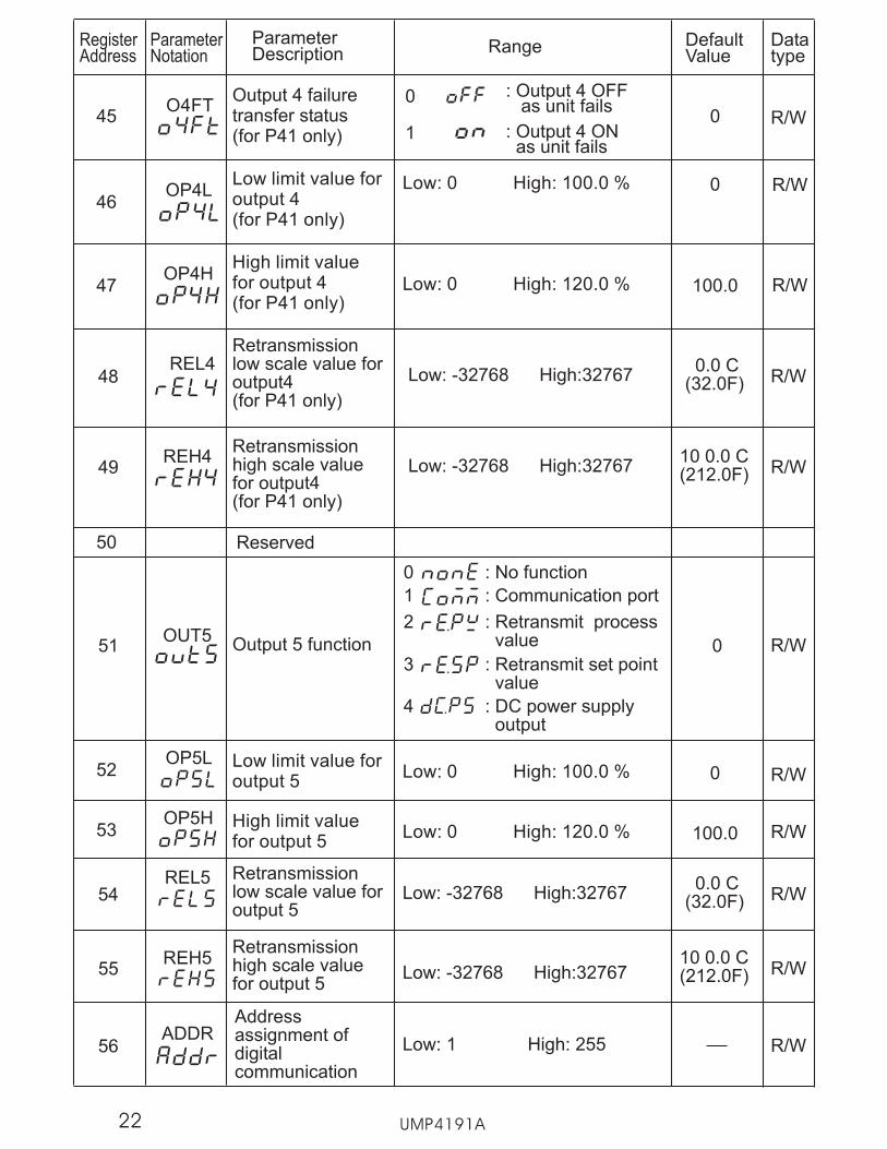
OUT4Output 4 function(for P41 only)
0 : No function
1 : Alarm 3 output
3 : Event 3 output 344 R/W
4 : Retransmit processvalue
5 : Retransmit set pointvalue
6 : DC power supplyoutput
21
3 : Event 2 output
2 : Reverse alarm 2output
2 : Reverse alarm 3output
ParameterNotation
ParameterDescription Range Default
ValueRegisterAddress
Datatype
48
Retransmissionlow scale value foroutput4(for P41 only)
Low: -32768 High:327670.0 C
(32.0F) R/W
49Retransmissionhigh scale valuefor output4(for P41 only)
Low: -32768 High:3276710 0.0 C(212.0F) R/W
Output 4 failuretransfer status(for P41 only)
045O4FT
Low limit value foroutput 5
Low: 0 High: 100.0 % 052
High limit valuefor output 5
Low: 0 High: 120.0 % 100.053
OP5L
OP5H
54Retransmissionlow scale value foroutput 5
Low: -32768 High:327670.0 C
(32.0F) R/W
55
Retransmissionhigh scale valuefor output 5
Low: -32768 High:3276710 0.0 C(212.0F) R/W
REL5
REH5
Output 5 function 051OUT5
0
1 : Output 4 ONas unit fails
: Output 4 OFFas unit fails
R/W
50
1 : Communication port
0 : No function
2 : Retransmit processvalue
3 : Retransmit set pointvalue
R/W
R/W
R/W
Reserved
UMP4191A
REH4
Low limit value foroutput 4(for P41 only)
Low: 0 High: 100.0 % 046
High limit valuefor output 4(for P41 only)
Low: 0 High: 120.0 % 100.047
R/W
R/W
OP4L
4 : DC power supplyoutput
Addressassignment ofdigitalcommunication
Low: 1 High: 255ADDR
56 R/W
22
OP4H
REL4

Baud rate of digitalcommunication 2
:0 2.4 Kbits/s baud rate
:1 4.8 Kbits/s baud rate
:2 9.6 Kbits/s baud rate
:3 14.4 Kbits/s baud rate
:4 19.2 Kbits/s baud rate
:5 28.8 Kbits/s baud rate
:6 38.4 Kbits/s baud rate
Parity bit of digitalcommunication
0 : Even parity
1 : Odd parity
2 : No parity bit
0
BAUD
PARI
UMP4191A
ParameterNotation
ParameterDescription Range Default
ValueRegisterAddress
Datatype
57
58
ALF1
0 : Process high alarm
1 : Process low alarm
2 : Deviation high alarm
3 : Deviation low alarm
4 : Deviation bandhigh/low alarm
Alarm 1 function 2
5 : End of profile alarm
6 : Hold mode alarm
7 : Static mode alarm
59
Alarm 1 operationmode
0
Low: 0.1 High:50.0 C(90.0 F)
LL
0.1 C(0.2 F)
A1HY Hysteresis controlfor alarm 1
A1MD60
61
R/W
R/W
R/W
R/W
R/W
23
0 : Normal alarm action
1 : Latching alarm action
2 : Hold alarm action
3 : Latching & holdalarm action
ParameterNotation
ParameterDescription Range Default
ValueRegisterAddress
Datatype
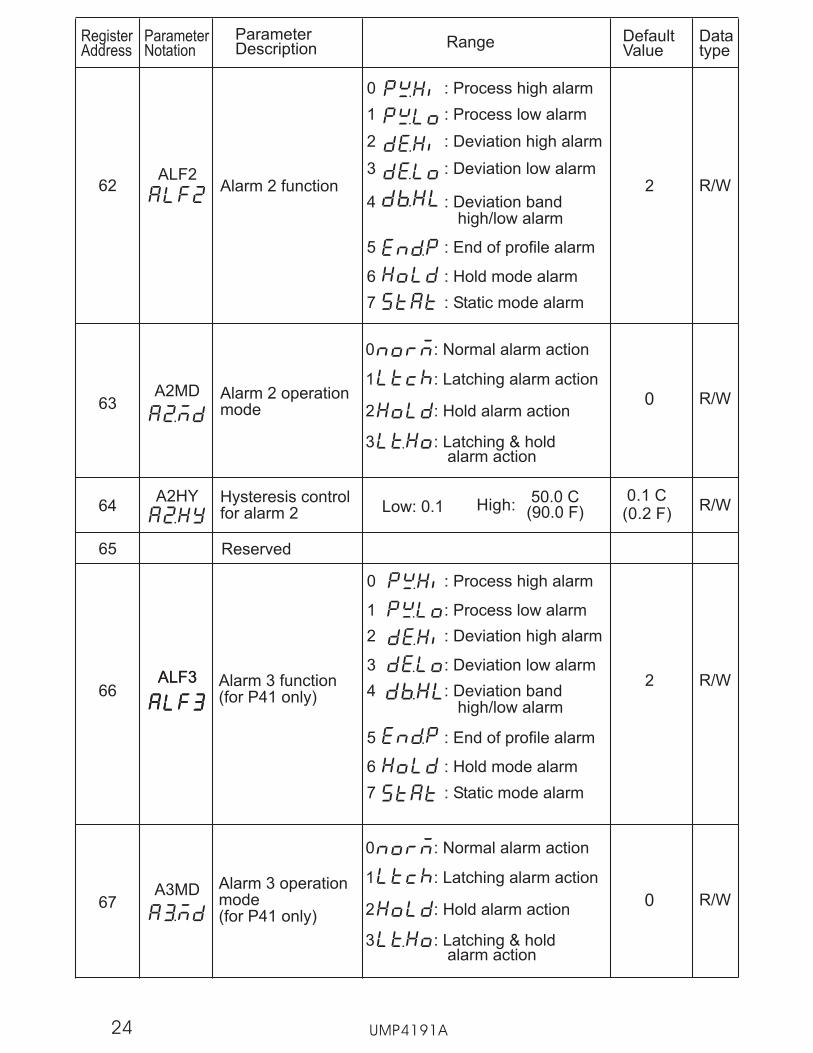
2Alarm 2 functionALF2
0 : Process high alarm
1 : Process low alarm
2 : Deviation high alarm
3 : Deviation low alarm
4 : Deviation bandhigh/low alarm
62
5 : End of profile alarm
6 : Hold mode alarm
7 : Static mode alarm
Alarm 2 operationmode
Low: 0.1 High:50.0 C(90.0 F)
0.1 C(0.2 F)
Hysteresis controlfor alarm 2
A2MD
A2HY
63
64
65
2 : Deviation high alarm
3 : Deviation low alarm
4 : Deviation bandhigh/low alarm
Alarm 3 function(for P41 only)
0 : Process high alarm
1 : Process low alarm
2ALF3ALF366
5 : End of profile alarm
6 : Hold mode alarm
7 : Static mode alarm
Alarm 3 operationmode(for P41 only)
A3MD67
R/W
R/W
R/W
R/W
R/W
Reserved
UMP4191A
0
0
24
0 : Normal alarm action
1 : Latching alarm action
2 : Hold alarm action
3 : Latching & holdalarm action
0 : Normal alarm action
1 : Latching alarm action
2 : Hold alarm action
3 : Latching & holdalarm action

ParameterNotation
ParameterDescription Range Default
ValueRegisterAddress
Datatype
Low: 0.1 High:50.0 C(90.0 F)
0.1 C(0.2 F)
Hysteresis controlfor alarm 3(for P41 only)
A3HY68
69
UMP4191A
R/W
Reserved
17
11
12
13
14
15
16
9
10
18
19
: selected forhome page
TD2
: CYC1 selectedfor home page
: CYC2 selectedfor home page
: CPB selected forhome page
: DB selected forhome page
: A1HY selectedfor home page
: A2HY selectedfor home page
: A3HY selectedfor home page
: ADDR selectedfor home page
: OFST selectedfor home page
: O1HY selectedfor home page
: TI2 selected forhome page
8
Select 2'ndparameterfor home page
Same as SEL1 2SEL2
Same as SEL1 3SEL3
7 : PB2 selected forhome page
6 : TD1 selected forhome page
Select 1'stparameter forhome page
0
1
2
5
: No parameterselected
1
: INPT selected forhome page
: UNIT selected forhome page
: TI1 selected forhome page
3 : DP selected forhome page
SEL1
70
4 : PB1 selected forhome page
71
72
R/W
R/W
R/WSelect 3'rdparameterfor home page
25

Select 4'thparameterfor home page
Same as SEL1 4SEL4
Select 5'thparameterfor home page
Same as SEL1 5SEL5
UMP4191A
ParameterNotation
ParameterDescription Range Default
ValueRegisterAddress
Datatype
73
74
R/W
R/W
Same as SEL1 19
Select 7'thparameterfor home page
Same as SEL1 12SEL7
SEL8 Select 8'thparameterfor home page
Select 6'thparameterfor home page
Same as SEL1 6SEL6
75
76
77
R/W
R/W
R/W
CODE78
Security code forparameterprotection
Low: 0 High: 9999
0=unprotected1000= home page unprotected
0 R/W
79 Reserved
80Set point value atstart of eachprofile
1 : Controller set pointvalue SP1
2 : Start set pointvalue STSP
0STAR
0 : Current processvalue PV
R/W
END Set point value atend of eachprofile
0 : Final set pointvalue for eachprogram
1 : Controller set pointvalue
0
DLAYDelay time ( hours/minutes) betweenprofile initiationand profile start
Low : 0.00 High : 99.59 0
2 : All outputs go to offexecpt end of profilerelay
81
82
R/W
R/W
26

UMP4191A
ParameterNotation
ParameterDescription Range Default
ValueRegisterAddress
Datatype
Power failrecovery
0 : Continue profilefrom the lastsetpoint value
2 : Static mode, SP1
2PFR
83
3 : OFF mode
84HBT Holdback wait
timeLow : 0.00 High : 99.59
(hour.minute) 1.00 R/W
R/W1 : Continue Profile
from current PV
85 Reserved
STSP Start set pointvalue
Low : SPLO High : SPHI
Unit for rampsegment
0 : Hours. Minutes
1 : Minutes. Seconds
2 : units per minute
3 : units per hour
86PROF Profile number
selected for viewLow: 1 High: 9 1 R/W
87
88
HBBD
RMPU
Holdback bandLow: 1 High: 555 C
(999F) R/W
R/W
R/W
R/W
R/W
R/W
89
90DLLU Unit for dwell
segment
0 : Hours. Minutes
1 : Minutes. Seconds
91 Segment numberLow : 0 High:15(PROF=1~4)
31(PROF=5~7)63(PROF=8,9)
SGNO
SGTY92
Segment type forthe selectedsegment number
0 : Ramp
1 : Dwell
2 : Jump
3 : End
3
R/W93TGSP
Low : SPLO High : SPHITarget set pointfor ramp segment
0.00= : infinite
27
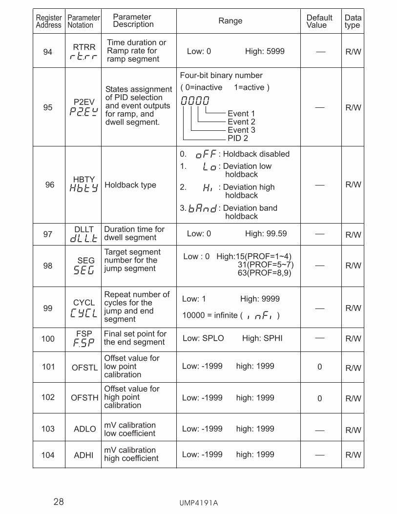
Four-bit binary number
( 0=inactive 1=active )
Event 1Event 2Event 3PID 2
UMP4191A
ParameterNotation
ParameterDescription Range Default
ValueRegisterAddress
Datatype
97DLLT
Low: 0 High: 99.59Duration time fordwell segment
95P2EV
States assignmentof PID selectionand event outputsfor ramp, anddwell segment.
96 Holdback type
0. : Holdback disabled
1. : Deviation lowholdback
2. : Deviation highholdback
3. : Deviation bandholdback
R/W
R/W
R/W
94RTRR
Low: 0 High: 5999 R/WTime duration orRamp rate forramp segment
HBTY
98SEG
Target segmentnumber for thejump segment
Low : 0 High:15(PROF=1~4)31(PROF=5~7)63(PROF=8,9)
R/W
Repeat number ofcycles for thejump and endsegment
CYCLLow: 1 High: 9999
10000 = infinite ( )R/W99
100FSP Final set point for
the end segment Low: SPLO High: SPHI R/W
101 OFSTL R/W
102 OFSTH R/W
103 ADLO R/W
Offset value forlow pointcalibration
Offset value forhigh pointcalibration
mV calibrationlow coefficient
Low: -1999 high: 1999 0
Low: -1999 high: 1999 0
Low: -1999 high: 1999
104 ADHI R/WmV calibrationhigh coefficient Low: -1999 high: 1999
28

ParameterNotation
ParameterDescription Range Default
ValueRegisterAddress
Datatype
105 RTDL R/W
106 RTDH R/W
107 CJLO R/W
108 CJHI R/W
109 DATE R/W
110 SRNO R/W
111
112 BPL1 R
113 BPL2 R
114 CJCL R
Date codeLow: 0 High: 3719
(9C31)
Serial number Low: 0 High: 9999
Bumpless transfervalue of MV1 Low: 0 High: 100.00
Sense voltagedurig cold junctioncalibration low
115
UMP4191A
RTD calibrationlow coefficient
RTD calibrationhigh coefficient
Cold junctioncalibration lowcoefficient
Cold junctioncalibration highcoefficient
Low: -1999 high: 1999
Low: -1999 high: 1999
Low: -5.00 high: 40.00
Low: -1999 high: 1999
Reserved
Bumpless transfervalue of MV2
Low: 0 High: 100.00
Low: 0 High: 7552
CALOR
CAHI116 R
Input signal valueduring low pointcalibration
Input signal valueduring high pointcalibration
Low: -32768 High: 32767
Low: -32768 High: 32767
0
1000
CAIN117 RInput sensorcalibrated Low: 0 High: 20 20
118
119
120
121
122
Reserved
Reserved
Reserved
Reserved
Reserved
29
ParameterNotation
ParameterDescription Range Default
ValueRegisterAddress
Datatype
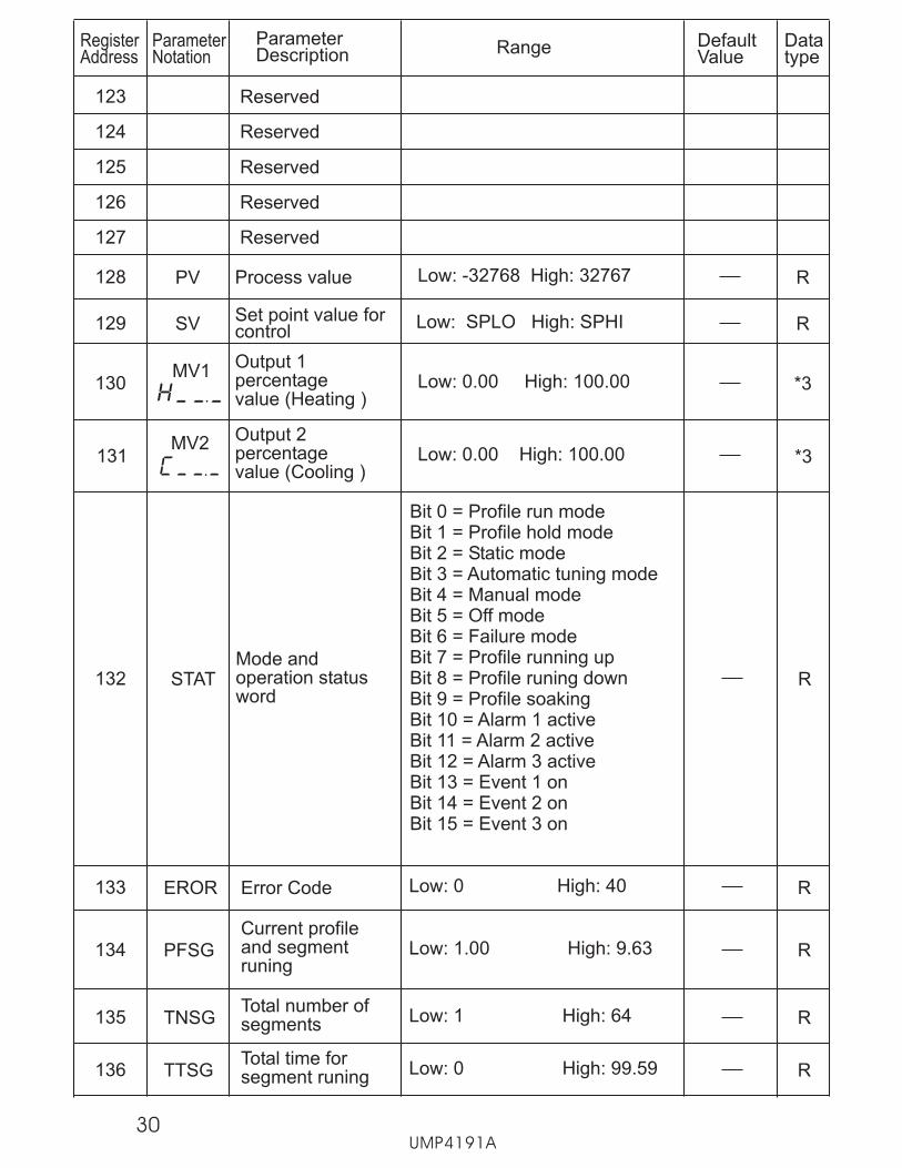
123
124
125
126
127 Reserved
Reserved
Reserved
Reserved
Reserved
UMP4191A
SVSet point value forcontrol
Low: SPLO High: SPHI129 R
PV Process value128 RLow: -32768 High: 32767
Output 1percentagevalue (Heating )
Output 2percentagevalue (Cooling )
Low: 0.00 High: 100.00
Low: 0.00 High: 100.00
MV1
MV2
130
131
*3
*3
132 STATMode andoperation statusword
Bit 0 = Profile run modeBit 1 = Profile hold modeBit 2 = Static modeBit 3 = Automatic tuning modeBit 4 = Manual modeBit 5 = Off modeBit 6 = Failure modeBit 7 = Profile running upBit 8 = Profile runing downBit 9 = Profile soakingBit 10 = Alarm 1 activeBit 11 = Alarm 2 activeBit 12 = Alarm 3 activeBit 13 = Event 1 onBit 14 = Event 2 onBit 15 = Event 3 on
R
133 EROR Error Code RLow: 0 High: 40
134 PFSG
Current profileand segmentruning
RLow: 1.00 High: 9.63
135 TNSGTotal number ofsegments RLow: 1 High: 64
136 TTSGTotal time forsegment runing RLow: 0 High: 99.59
30

*3 Read only unless in manual control mode.
ParameterNotation
ParameterDescription Range Default
ValueRegisterAddress
Datatype
137Set point forcurrent segment
140 PROG
Program andversion codeof the product
R
142 CMND Command code R/W
Low: -32768 High: 32767
Low: -32768 High: 32767
143 JOB Job code R/WLow: -32768 High: 32767
SPSG Low:SPLO High: SPHI R
138Time remainingfor the currentsegment
TIME Low:00.00 High: 99.59 R
139**Cycle remainingfor the currentloop
CYCLLow:1 High: 9999
10000=infinite R
141 HBTR
Holdback timeremaning for thecurrent segment
RLow: 0 High: 99.59
UMP4191A31
NOTES
*2 Once the unit has been configured under a specific decimal point selection,changing the decimal point setting (DP) will require the entire unit to bereconfigured to maintain previous control settings. Profiles, alarm set points,set point limits, etc., DO NOT automatically scale, i.e., 100.0 becomes 1000(not 100), and must be set up again manually.
*1 Controller memory has a maximum life of one million (1,000,000) write cycles. Ifthe controller is operated by a supervisory control system, avoid excessive set pointwrites to the controller or premature failure of the controller may result. Units withversion number V.19 and later have been updated to write the set point (when sentvia communications) to memory once every 6 minutes allowing unlimited set pointwrites to the controller for a life span of greater than 10 years.
** NOTE Cycles rregister indicates “current cycles remaining” for last jump segment(outer jump) and NOT inner jump segments.
Dangerous voltages capable of causing serious injury or deathmay be present in this instrument. Before installation or prior to
beginning any cleaning or troubleshooting procedures, turn off powerto all equipment and follow proper lockout-tagout procedures. Unitssuspected of being faulty should be disconnected and removed to aproperly equipped workshop for testing and repair. Componentreplacement and internal adjustments must be made by a qualifiedmaintenance person only.
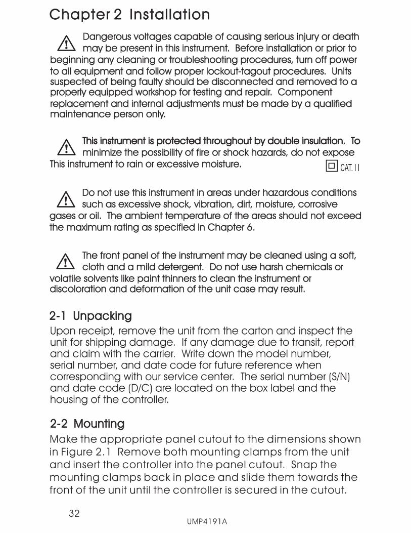
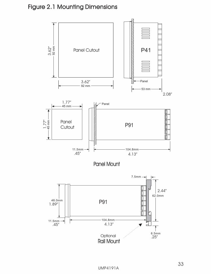
2-2 Mounting2-2 Mounting
Make the appropriate panel cutout to the dimensions shownin Figure 2.1 Remove
.
both mounting clamps from the unitand insert the controller into the panel cutout. Snap themounting clamps back in place and slide them towards thefront of the unit until the controller is secured in the cutout
Chapter 2 Instal lat ionChapter 2 Instal lat ion
Do not use this instrument in areas under hazardous conditionssuch as excessive shock, vibration, dirt, moisture, corrosive
gases or oil. The ambient temperature of the areas should not exceedthe maximum rating as specified in Chapter 6.
Do not use this instrument in areas under hazardous conditionssuch as excessive shock, vibration, dirt, moisture, corrosive
gases or oil. The ambient temperature of the areas should not exceedthe maximum rating as specified in Chapter 6.
2-1 Unpacking2-1 Unpacking
Upon receipt, remove the unit from the carton and inspect theunit for shipping damage. If any damage due to transit, reportand claim with the carrier. Write down the model number,serial number, and date code for future reference whencorresponding with our service center. The serial number (S/N)and date code (D/C) are located on the box label and thehousing of the controller.
This instrument is protected throughout by double insulation. Tominimize the possibility of fire or shock hazards, do not expose
This instrument to rain or excessive moisture.
This instrument is protected throughout by double insulation. Tominimize the possibility of fire or shock hazards, do not expose
This instrument to rain or excessive moisture.
The front panel of the instrument may be cleaned using a soft,cloth and a mild detergent. Do not use harsh chemicals or
volatile solvents like paint thinners to clean the instrument ordiscoloration and deformation of the unit case may result.
The front panel of the instrument may be cleaned using a soft,cloth and a mild detergent. Do not use harsh chemicals or
volatile solvents like paint thinners to clean the instrument ordiscoloration and deformation of the unit case may result.
UMP4191A32
CAT. I I
53 mm
Panel
92
mm
92 mm
Panel Cutout P41
Figure 2.1 Mounting DimensionsFigure 2.1 Mounting Dimensions
UMP4191A33
45 mm
45
mm Panel
Cutout
104.8mm
Panel
11.5mm
Panel MountPanel Mount
104.8mm11.5mm
62.0mm
6.5mm
7.5mm
48.0mm P91
Rail MountRail Mount
3.62”
2.08”
3.6
2”
4.13”.45”
1.77”
1.7
7”
1.89”
.45” 4.13”
Optional
2.44”
.25”
P91

2 - 3 Wiring Precautions2 - 3 Wiring Precautions
Before wiring, check the label for the correct model number,voltage rating and options.
Care must be taken to ensure that the maximum voltagerating specified on the label is not exceeded.
It is recommended that power wiring of the unit be protected byfuses or circuit breakers rated at the minimum value possible.
The unit should be installed inside a suitably grounded metalenclosure to prevent live parts from being accessed by humanhands or metal tools.
All wiring must conform to appropriate standards of good practiceand local codes and regulations. Wiring must be suitable forvoltage, current, and temperature rating of the system.
not over-tighten the terminal screws. The torque should notexceed 1 N-m ( 8.9 Lb-in or 10.2KgF-cm ).Do
*
*
*
*
*
*
UMP4191A
Figure 2.3 Lead Termination for P91Figure 2.3 Lead Termination for P91
7.0mm max.3.2mm min.
6.0mm max.
3.0mm min.
Figure 2.2 Lead Termination for P41Figure 2.2 Lead Termination for P41
Unused control terminals should not be used as jumper pointsfor other wiring as they may be internally connected, causingdamage to the unit.
Verify that the ratings of the input and output devices connectedto the controller do not exceed those specified in Chapter 6.
Except for thermocouple wiring, all wiring should use strandedcopper conductors with a maximum of 18 AWG.
*
*
*
34
1
2
3
4
5
6
7
8
9
13
12
11
14
15
16
17
18
19
20
90-250VAC47-63 Hz12VA
90-250VAC47-63 Hz12VA
L
N
Out1
_
+
Out2
_
+Out3
B
B
A
RTD
_ _
+ +
V _
+
PTA
TC+, V+PTB, mA+TC+, V+PTB, mA+
TC-, V-PTB, mA-TC-, V-PTB, mA-
TC V mA RTD
10
C
NO
C
NO
NC
C
NO
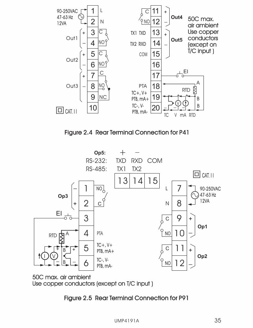
Figure 2.4 Rear Terminal Connection for P41Figure 2.4 Rear Terminal Connection for P41
50C max.air ambientUse copperconductors(except onT/C input )
50C max.air ambientUse copperconductors(except onT/C input )
CAT. I I
EI
Out4
_
+
UMP4191A
_
+
35
C
NO
TX1 TXDTX1 TXD
TX2 RXDTX2 RXD
COM
Out5
_
+
1
2
3
4
5
6
7
8
9
10
11
12__
++
IB
B
ARTD
V
Op3
90-250VAC47-63 Hz12VA
90-250VAC47-63 Hz12VA
L
N
C
NO
C
NO
_
+
Op2
_
+
13 14 15
RS-232: TXD
TX1 TX2
RXD COM
RS-485:
Op1
PTA
TC+, V+PTB, mA+TC+, V+PTB, mA+
TC-, V-PTB, mA-TC-, V-PTB, mA-
50C max. air ambientUse copper conductors (except on T/C input )50C max. air ambientUse copper conductors (except on T/C input )
CAT. I I
Op5: +
C
NO
EI
+
_
Figure 2.5 Rear Terminal Connection for P91Figure 2.5 Rear Terminal Connection for P91
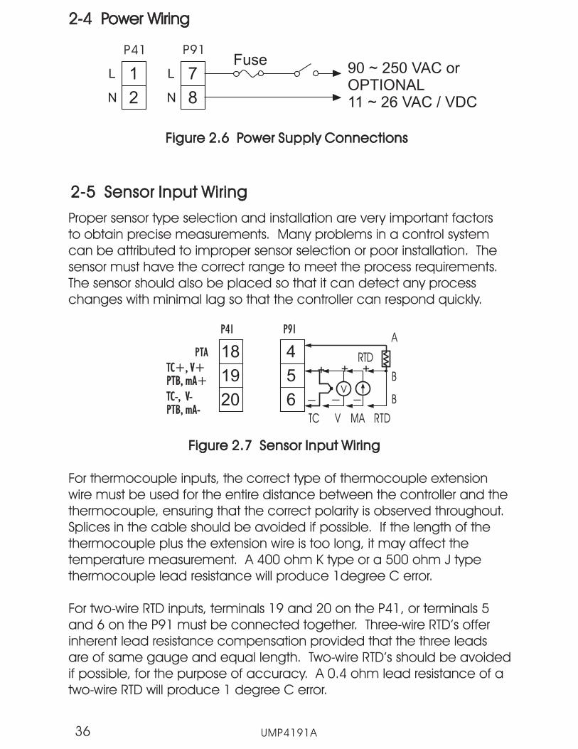
2-4 Power Wiring2-4 Power Wiring
90 ~ 250 VAC orOPTIONAL11 ~ 26 VAC / VDC
Figure 2.6 Power Supply ConnectionsFigure 2.6 Power Supply Connections
1
2
L
N
7
8
L
N
P41 P91Fuse
2-5 Sensor Input Wiring2-5 Sensor Input Wiring
18 4
19 5
20 6
P41 P91
PTA
TC+, V+PTB, mA+TC+, V+PTB, mA+
TC-, V-PTB, mA-TC-, V-PTB, mA-
B
B
A
RTD
_ _
+ +
V _
+
TC V MA RTD
Figure 2.7 Sensor Input WiringFigure 2.7 Sensor Input Wiring
UMP4191A36
Proper sensor type selection and installation are very important factorsto obtain precise measurements. Many problems in a control systemcan be attributed to improper sensor selection or poor installation.
The sensor should also be placed so that it can detect any processchanges with minimal lag so that the controller can respond quickly.
For thermocouple inputs, the correct type of thermocouple extensionwire must be used for the entire distance between the controller and thethermocouple, ensuring that the correct polarity is observed throughout.Splices in the cable should be avoided if possible. If the length of thethermocouple plus the extension wire is too long, it may affect thetemperature measurement. A 400 ohm K type or a 500 ohm J typethermocouple lead resistance will produce 1degree C error.
For two-wire RTD inputs, terminals 19 and 20 on the P41, or terminals 5and 6 on the P91 must be connected together. Three-wire RTD’s offerinherent lead resistance compensation provided that the three leadsare of same gauge and equal length. Two-wire RTD’s should be avoidedif possible, for the purpose of accuracy. A 0.4 ohm lead resistance of atwo-wire RTD will produce 1 degree C error.
Thesensor must have the correct range to meet the process requirements.
Load
120V /240VMains Supply120V /240VMains Supply
SSR
30mA / 5VPulsedVoltage
30mA / 5VPulsedVoltage
Internal CircuitInternal Circuit
+
5V
0V
33
33
_
+
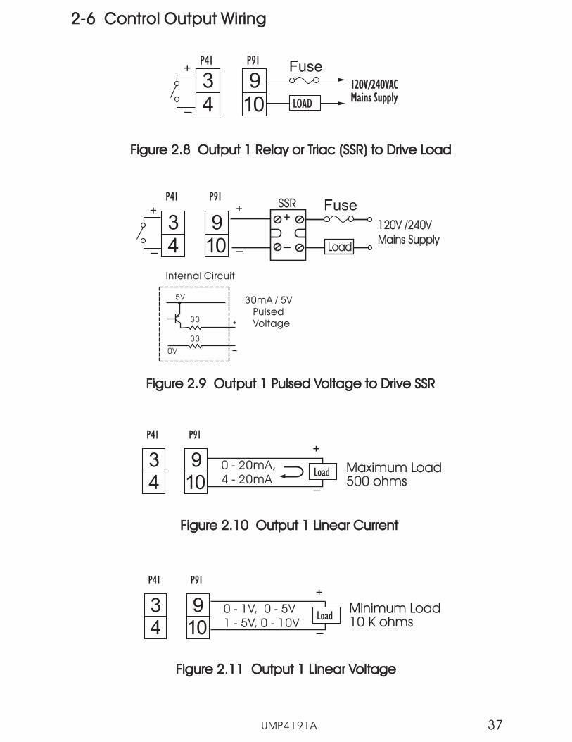
Figure 2.9 Output 1 Pulsed Voltage to Drive SSRFigure 2.9 Output 1 Pulsed Voltage to Drive SSR
+
_
34
P41 P91
910_
+
UMP4191A 37
0 - 1V, 0 - 5V1 - 5V, 0 - 10V0 - 1V, 0 - 5V1 - 5V, 0 - 10V
Maximum Load500 ohmsMaximum Load500 ohms
Minimum Load10 K ohmsMinimum Load10 K ohms
0 - 20mA,4 - 20mA0 - 20mA,4 - 20mA _
+
Load
_
+
Load
Figure 2.10 Output 1 Linear CurrentFigure 2.10 Output 1 Linear Current
Figure 2.11 Output 1 Linear VoltageFigure 2.11 Output 1 Linear Voltage
34
P41 P91
910
34
P41 P91
910
Fuse
34
P41 P91
910_
+
120V/240VACMains Supply120V/240VACMains Supply
Figure 2.8 Output 1 Relay or Triac (SSR) to Drive LoadFigure 2.8 Output 1 Relay or Triac (SSR) to Drive Load
LOAD
Fuse
2-6 Control Output Wiring2-6 Control Output Wiring

UMP4191A38
Load
120V /240VMains Supply120V /240VMains Supply
SSR
30mA / 5VPulsedVoltage
30mA / 5VPulsedVoltage
Internal CircuitInternal Circuit
+
5V
0V
33
33
_
+
Figure 2.13 Output 2 Pulsed Voltage to Drive SSRFigure 2.13 Output 2 Pulsed Voltage to Drive SSR
+
_
56
P41 P91
1112_
+ Fuse
0 - 1V, 0 - 5V1 - 5V, 0 - 10V0 - 1V, 0 - 5V1 - 5V, 0 - 10V
Maximum Load500 ohmsMaximum Load500 ohms
Minimum Load10 K ohmsMinimum Load10 K ohms
0 - 20mA,4 - 20mA0 - 20mA,4 - 20mA _
+
Load
_
+
Load
Figure 2.14 Output 2 Linear CurrentFigure 2.14 Output 2 Linear Current
Figure 2.15 Output 2 Linear VoltageFigure 2.15 Output 2 Linear Voltage
56
P41 P91
1112
P41 P91
1112
56
120V/240VACMains Supply120V/240VACMains Supply
Figure 2.12 Output 2 Relay or Triac (SSR) to Drive LoadFigure 2.12 Output 2 Relay or Triac (SSR) to Drive Load
56
P41 P91
1112_
+
LOAD
Fuse
UMP4191A 39
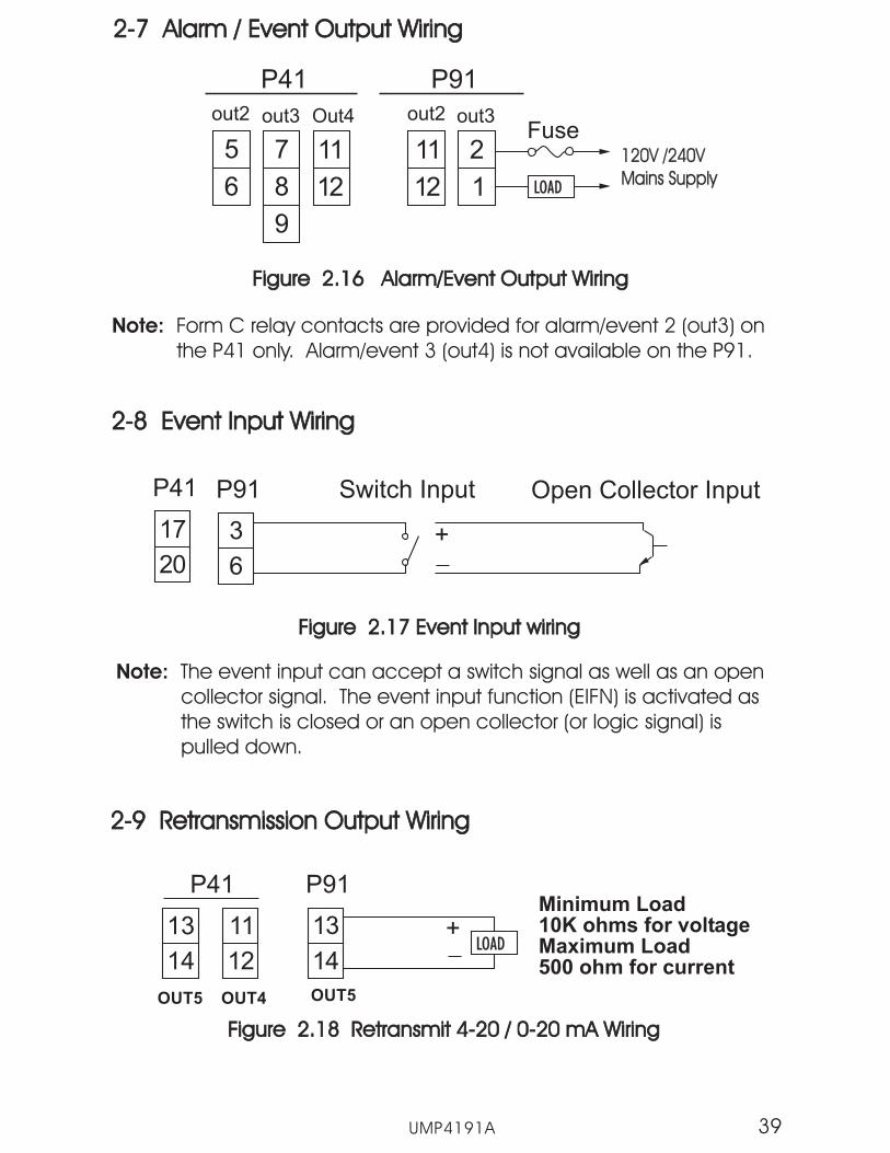
2-7 Alarm / Event Output Wiring2-7 Alarm / Event Output Wiring
Figure 2.16 Alarm/Event Output WiringFigure 2.16 Alarm/Event Output Wiring
P41
5
6
out2
7
8
9
out3
11
12
Out4
P91
11
12
out2
2
1
out3
LOAD
Fuse
Note: Form C relay contacts are provided for alarm/event 2 (out3) onthe P41 only. Alarm/event 3 (out4) is not available on the P91.
2-8 Event Input Wiring2-8 Event Input Wiring
17
20
Figure 2.17 Event Input wiringFigure 2.17 Event Input wiring
3
6
P41 P91 Switch Input
2-9 Retransmission Output Wiring2-9 Retransmission Output Wiring
11
12
Figure 2.18 Retransmit 4-20 / 0-20 mA WiringFigure 2.18 Retransmit 4-20 / 0-20 mA Wiring
13
14
P41 P91Minimum Load10K ohms for voltageMaximum Load500 ohm for current
13
14LOAD
+
Note: The event input can accept a switch signal as well as an opencollector signal. The event input function (EIFN) is activated asthe switch is closed or an open collector (or logic signal) ispulled down.
Open Collector Input
+
120V /240VMains Supply120V /240VMains Supply
OUT5 OUT4 OUT5
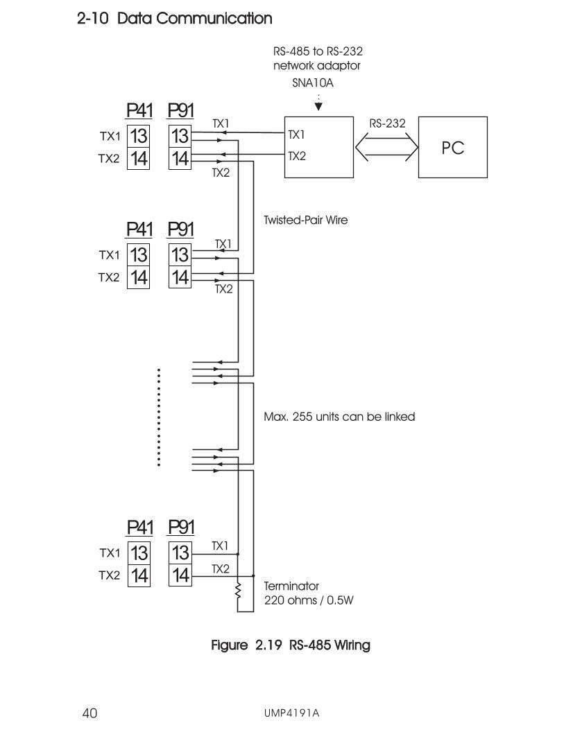
2-10 Data Communication2-10 Data Communication
UMP4191A40
1314
TX1
TX2
TX1TX1
TX1
TX1
TX2
TX2
TX2
TX2
Terminator220 ohms / 0.5WTerminator220 ohms / 0.5W
Max. 255 units can be linkedMax. 255 units can be linked
RS-232
PC
SNA10A
RS-485 to RS-232network adaptorRS-485 to RS-232network adaptor
Twisted-Pair WireTwisted-Pair Wire
Figure 2.19 RS-485 WiringFigure 2.19 RS-485 Wiring
P91
1314
TX1
TX2
P91
1314
TX1
TX2
P91
1314
P41
1314
P41
1314
P41

PC
9-pinRS-232port
9-pinRS-232port
Figure 2.20 RS-232 WiringFigure 2.20 RS-232 Wiring
CC94-1
131415
NOTE: If you use a conventional 9-pin RS-232 cable insteadof CC94-1, the cable must be modified accordingto the following circuit diagram.
NOTE: If you use a conventional 9-pin RS-232 cable insteadof CC94-1, the cable must be modified accordingto the following circuit diagram.
1
2
3
4
5
6
7
8
9
TX1 RD
TX2 TD
COM
GND
Female DB-9Female DB-9
To DTE ( PC ) RS-232 PortTo DTE ( PC ) RS-232 Port
1 DCD2 RD3 TD4 DTR5 GND6 DSR7 RTS8 CTS9 RI
1 DCD2 RD3 TD4 DTR5 GND6 DSR7 RTS8 CTS9 RI
Figure 2.21 Configuration of RS-232 CableFigure 2.21 Configuration of RS-232 Cable
P91
TXD
RXD
COM
131415
P91
UMP4191A 41
131415
P41
TXD
RXD
COM
131415
P41
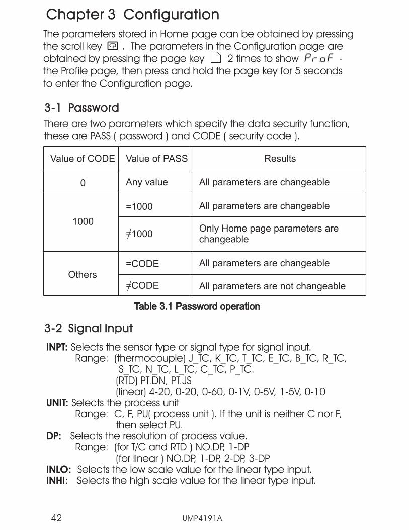
Chapter 3 ConfigurationChapter 3 Configuration
3-1 Password3-1 Password
The parameters stored in Home page can be obtained by pressingthe scroll key . The parameters in the Configuration page areobtained by pressing the page key 2 times to show -the Profile page, then press and hold the page key for 5 secondsto enter the Configuration page.
There are two parameters which specify the data security function,these are PASS ( password ) and CODE ( security code ).
Value of CODE Value of PASS Results
All parameters are changeable0
1000
Any value
=1000 All parameters are changeable
Only Home page parameters arechangeable
All parameters are changeable
All parameters are not changeable
=CODE
=1000
=CODEOthers
Table 3.1 Password operationTable 3.1 Password operation
3-2 Signal Input3-2 Signal Input
INPT:
UNIT:
DP:
INLO:INHI:
Selects the sensor type or signal type for signal input.Range: (thermocouple) J_TC, K_TC, T_TC, E_TC, B_TC, R_TC,
S_TC, N_TC, L_TC, C_TC, P_TC.(RTD) PT.DN, PT.JS(linear) 4-20, 0-20, 0-60, 0-1V, 0-5V, 1-5V, 0-10
Selects the process unitRange: C, F, PU( process unit ). If the unit is neither C nor F,
then select PU.Selects the resolution of process value.Range: (for T/C and RTD ) NO.DP, 1-DP
(for linear ) NO.DP, 1-DP, 2-DP, 3-DPSelects the low scale value for the linear type input.Selects the high scale value for the linear type input.
UMP4191A42
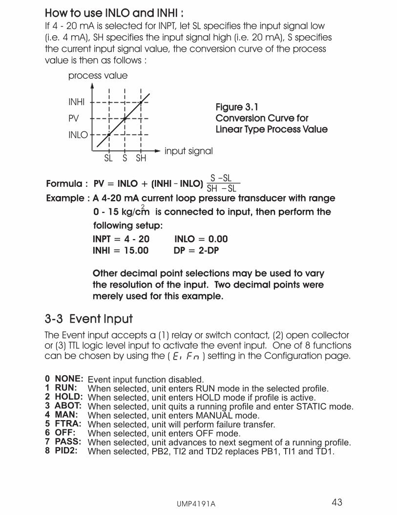
How to use INLO and INHI :How to use INLO and INHI :If 4 - 20 mA is selected for INPT, let SL specifies the input signal low(i.e. 4 mA), SH specifies the input signal high (i.e. 20 mA), S specifiesthe current input signal value, the conversion curve of the processvalue is then as follows :
INHI
process value
PV
INLO
SL SHSinput signal
Figure 3.1Conversion Curve forLinear Type Process Value
Figure 3.1Conversion Curve forLinear Type Process Value
Formula : PV = INLO + (INHI INLO)S SLS SL
SH SLSH SLExample : A 4-20 mA current loop pressure transducer with range
0 - 15 kg/cm is connected to input, then perform the
following setup:
2
INPT = 4 - 20 INLO = 0.00
INHI = 15.00 DP = 2-DP
Other decimal point selections may be used to vary
the resolution of the input. Two decimal points were
merely used for this example.
3-3 Event Input3-3 Event Input
The Event input accepts a (1) relay or switch contact, (2) open collectoror (3) TTL logic level input to activate the event input. One of 8 functionscan be chosen by using the ( ) setting in the Configuration page.
0 NONE:1 RUN:2 HOLD:3 ABOT:4 MAN:5 FTRA:6 OFF:7 PASS:8 PID2:
43UMP4191A
Event input function disabled.When selected, unit enters RUN mode in the selected profile.When selected, unit enters HOLD mode if profile is active.When selected, unit quits a running profile and enter STATIC mode.When selected, unit enters MANUAL mode.When selected, unit will perform failure transfer.When selected, unit enters OFF mode.When selected, unit advances to next segment of a running profile.When selected, PB2, TI2 and TD2 replaces PB1, TI1 and TD1.

There are five control mode types that can be configured for theP series as shown in Table 3.2.
3-4 Control Outputs3-4 Control Outputs
: Don't care
:Required to adjust if ON-OFF control is configured.
ControlModes
OUT1 OUT2 O1HY A1HY CPB DB
Heat only
Cool only
Heat: PIDCool: ON-OFF
Heat: PIDCool: PID
Heat: ON-OFFCool: ON-OFF
:Adjust to meet process requirements
Table 3.2 Heat-Cool Control Configuration ValueTable 3.2 Heat-Cool Control Configuration Value
Heat Only ON-OFF Control: Select for OUT1 and use O1HYto adjust the dead band for ON-OFF control. The heat only on-offcontrol function is shown in the following diagram.
UMP4191A44
NOTE: The ON-OFF control mode may introduce excessive processoscillation even if the hysteresis is minimized to the smallest possiblevalue. When ON-OFF control is selected, PB1, TI1, TD1, PB2, TI2, TD2,CYC1, CYC2, OFST, CPB and DB will be hidden and have no functionin the control. The auto-tuning mode and bumpless transfer are alsodisabled.

SP1
(SP1 O1HY)
ON
OFF
Output 1 Action
PV
Dead band = O1HY
Time
Time
Figure 3.2 Heat Only ON-OFF ControlFigure 3.2 Heat Only ON-OFF Control
Select or for OUT1 andset TI1 and TI2 to ZERO. OFST is then used to adjust the control offset(manual reset) and O1HY is hidden. OFST is measured in % with arange of 0-100.0%. Under steady state operation (i.e. the process hasstabilized), if the process value is lower than the set point by 5°C forexample, and 20°C is used for the proportional band, that equals anoffset of 25%. Thus, increase the OFST value by 25% and it willcompensate for set point offset in the process. After adjusting OFST toa new value, the process value will move to coincide with set point.The auto-tuning mode is disabled for P or PD control. Refer to section3-11 for manual tuning. P or PD control is not precise for processeswith changing load conditions and will require frequent adjustmentsto the OFST. The PID control mode should thus be used because itautomatically does this for you.
Heat only P (or PD) control:
UMP4191A 45
Cool only control: ON-OFF control, P (or PD) control and PIDcontrol can be selected for cool only control through output 1.Set OUT1 to , or . The operation of coolonly ON-OFF control, cool only P (or PD) control and cool onlyPID control are same as the descriptions for heat only controlexcept that the output variable (and action) for cooling controlis the opposite of heating control.
Heat only PID control: Set or for OUT1 and non-zerovalues for the proportional band and integral time. Perform an autotune to obtain the proper tuning parameter values or set appropriatevalues for PB1, TI1 and TD1. If the control result is still unsatisfactory, itmay be necessary to perform manual tuning to improve the control.See section 3-11 for manual tuning. The unit contains an intelligentPID and fuzzy control algorithm to achieve a very small overshootand very quick response to the process if tuned properly.
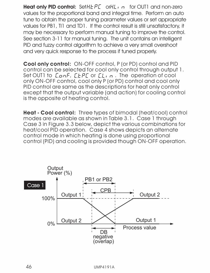
Heat - Cool control: Three types of bimodal (heat/cool) controlmodes are available as shown in Table 3.1. Case 1 throughCase 3 in Figure 3.3 below, depict the various combinations forheat/cool PID operation. Case 4 shows depicts an alternatecontrol mode in which heating is done using proportionalcontrol (PID) and cooling is provided though ON-OFF operation.
0%
OutputPower (%)
Process value
100%
DBnegative(overlap)
CPB
PB1 or PB2
Output 1
Output 2
Output 2
Output 1
Case 1Case 1
UMP4191A46

0%
OutputPower (%)
Process value
100%
DBpositive
CPBPB1 or PB2
Output 1
Output 2
Output 2
Output 1
Case 2Case 2
0%
OutputPower (%)
Process value
100%
DB=0
CPBPB1 or PB2
Output 1
Output 2
Output 2
Output 1
Case 3Case 3
0%
OutputPower (%)
Process value
100%
SV
A1HYPB1 or PB2
Output 1
Output 2
Output 2
Output 1
Case 4Case 4
OUT2 = ALM1
ALF1 =
ASP1 = A1HY
Figure 3.3 Heat - cool ControlFigure 3.3 Heat - cool Control
Ou
tpu
t2
OF
FO
utp
ut
2O
N
UMP4191A 47

DB Configuration: Adjustment of DB is more dependent upon systemrequirements. If more positive values of DB (greater dead band) areused, an unwanted cooling action can be avoided but an excessiveovershoot will occur. If more negative values of DB (greater overlap) areused, an excessive overshoot can be minimized but an unwantedcooling action may occur. DB is adjustable in the range of -36.0% to36.0 % of PB. A negative DB value provides an overlap between heatingand cooling in which both outputs are active. A positive DB valueprovides a dead band area in which neither output is active around setpoint.
NOTE : For bimodal (heat/cool) operation, ON-OFF control may result inexcessive overshoot and undershoot problems in the process. The P(or PID) control will result in the process value constantly deviating fromset point. It is recommended to use PID control for the heat/cooloperation to produce a stable and zero offset process value.
CYC1, CYC2, O1FT and O2FT Configuration: The output cycle times,CYC1 and CYC2 should be adjusted according to the type of outputdevice. Generally, a 0.5~2 sec. can be used if a solid state relay driveor solid relay (triac) is installed for the output. If a relay is installed for theoutput, a 10~20 sec. cycle time is used. If a linear output (voltage orcurrent) is used, the cycle time can be ignored.
See for O1FT and O2FT adjustment.Section 3-9
CPB Configuration: The cooling proportional band is measured in % ofThe proportional band (PB) with a range 50-300. Set CPB to 100% tobegin and examine the cooling effect. If cooling action should beenhanced then decrease CPB. If cooling action is too strong thenincrease CPB. The value of CPB is related to PB and its value remainsunchanged throughout any auto-tuning procedures.
UMP4191A48
NOTE: The adjustment of CPB is also related to the cooling media used.When air is used as the cooling media, it is recommended that CPB beset to 100%. For oil, a typical setting to use for CPB is 125%. If water isused as the cooling media, adjust CPB to 250%.

3-5 Alarms3-5 Alarms
The unit can be configured with up to three alarm outputs on the P41at OUT2, OUT3 and OUT4 and up to two alarm outputs on the P91 atOUT2 and OUT3. There are 8 alarm functions and 4 alarm modesavailable for each alarm output.
: A process high alarm is independent of set point. When theprocess is higher than the alarm set point, a process high alarm occurs.When the process value is lower than the alarm set point minus thealarm hysteresis, the alarm is off.
Figure 3.4 Process High Alarm 1 OperationFigure 3.4 Process High Alarm 1 Operation
Output 2onoff
Alarm SetpointASP1ASP1-A1HY
OUT2=ALM1
Output 2onoff
Figure 3.5 Process Low Alarm 1 OperationFigure 3.5 Process Low Alarm 1 Operation
Output 2onoff
Process value
Alarm SetpointASP1+A1HYASP1
Output 2onoff
: A process low alarm is independent of set point. When theprocess is lower than the alarm set point, a process low alarm occurs.When the process value is above the alarm set point plus the alarmhysteresis, the alarm is off.
Process value
UMP4191A 49
OUT2=rAL1
OUT2=ALM1
OUT2=rAL1

: A deviation high alarm is dependant upon the control set pointand alerts the operator when the process deviates too high over theset point value. When the process is higher than SV+ASP1 (NOTE: ASP1must be entered as a positive value), a deviation high alarm occurs.When the process falls below SV+ASP1-A1HY, the alarm is off.
Figure 3.6 Deviation High Alarm 1 OperationFigure 3.6 Deviation High Alarm 1 Operation
Output 2onoff
Process value
SV+ASP1SV+ASP1-A1HY
Output 2onoff
Figure 3.7 Deviation Low Alarm 1 OperationFigure 3.7 Deviation Low Alarm 1 Operation
Output 2onoff
SV+ASP1+A1HYSV+ASP1
Output 2onoff
Alarm Setpoint
SV (set point value)
Process value
: A deviation low alarm is dependant upon the control set pointand alerts the operator when the process deviates too low below theset point value. When the process is lower than SV+ASP1 (NOTE: ASP1must be entered as a negative value), a deviation low alarm occurs.When the process is higher than SV+ASP1+ A1HY, the alarm is off.
Alarm SetpointSV (set point value)
UMP4191A50
OUT2=ALM1
OUT2=rAL1
OUT2=ALM1
OUT2=rAL1

: A deviation band high/low alarm presets two trigger levelsrelative to the control set point value. The two trigger levels areSV+ASP1 and SV-ASP1 for the high and low alarm values. When theprocess is higher than SV+ASP1 or lower than SV-ASP1, a deviationband alarm occurs. When the process is within the trigger levels,SV+ASP1-A1HY and SV-ASP1+ A1HY, the deviation band alarm is off.
NOTE: ASP1 must be entered as a positive value.
Figure 3.8 Deviation Band Alarm 1 OperationFigure 3.8 Deviation Band Alarm 1 Operation
Output 2onoff
Process value
Alarm value
SV+ASP1SV+ASP1-A1HY
Output 2onoff
Alarm value
SV-ASP1SV-ASP1+A1HY
SV(set point value)
NOTE: The settings and operation of alarm 2 and alarm 3 are thesame as those described for alarm 1. In the above descriptions, SVdenotes the current set point value for control which is different fromSP1 when in the profile mode of operation.
UMP4191A 51
OUT2=ALM1
OUT2=rAL1

The alarm modes (A1MD, A2MD and A3MD) are set by using a three bitbinary number.
alarmmodevalue
Description
A direct acting normal alarm output is off as the non-alarmcondition and on as an alarm condition. The output state isinverted as a reverse alarm output is selected for OUT2, OUT3or OUT4.
A direct acting latching alarm output is on as an alarmcondition and it will remain unchanged even if the alarmcondition is cleared. The output state is inverted as a reversealarm output is selected for OUT2, OUT3 or OUT4.
A direct acting holding alarm output is off even if an alarmcondition may occur on power up. This will prevail until thealarm condition returns to the "inactive" condition, thereafter thealarm will operate normally. The output state is inverted as areverse alarm output is selected for OUT2, OUT3 or OUT4.
A direct acting and alarm performs bothholding and latching alarm functions.
latching holdingThe output state is
inverted as a reverse alarm output is selected for OUT2, OUT3or OUT4.
latching holding
Table 3.3 Alarm mode descriptionTable 3.3 Alarm mode description
The latching alarm output is reset when both and keys arepressed at the same time and the alarm condition is no longer present.
UMP4191A52
3-6 Configure Home Page3-6 Configure Home Page
Conventional controllers are designed with fixed parameter scrolling.The “P” Series has the flexibility for you to select the parameters whichare most useful to you and put these parameters in the home page.Hence, you can have a custom home page.
There are up to eight parameters can be displayed on the home page.These are the SEL1~SEL8 parameters in the configuration page. Eachparameter can be configured to display one of 19 parameters: INPT,UNIT, DP, PB1, TI1, TD1, PB2, TI2, TD2, OFST, O1HY, CYC1, CYC2, CPB, DB,A1HY, A2HY, A3HY and ADDR. Note that not all of the 19 parametersmay be available as some of the selections or only visible based onthe configuration of the controller.
3-7 User Calibration3-7 User Calibration
Each unit is calibrated at the factory before shipment; however, theunit can be re-calibrated in the field with the use of proper calibrationequipment.
Purpose of User CalibrationPurpose of User Calibration
The basic calibration of the unit is highly stable and set for life. Usercalibration allows you to offset the permanent factory calibration toeither:
1. Calibrate the unit to meet your reference standard.2. Match the calibration of the unit to that of a particular transducer or
sensor input.3. Calibrate the unit to suit the characteristics of a particular installation.4. Remove long term drift in the factory set calibration.
There are two parameters: offset low value (OFSTL) and offset highvalue (OFSTH) which can be adjusted to correct the error in the processvalue reading. See Section 1-5 for the key operation flowchart; pressthe key until the low calibration page is obtained.
UMP4191A 53

Displayedvalue
Offsetintroduced
FactoryCalibration
UserCalibrationOffset
introducedDesired highpoint value
High pointcalibration
Low pointcalibration
Desired lowpoint value Input signal
Figure 3.9 Two Point User CalibrationFigure 3.9 Two Point User Calibration
The two point offset constructs a straight line (linear calibration)between the two points. To insure greatest accuracy, it is best tocalibrate with the two points at the minimum and maximumoperating ranges of the system. After user calibration is complete,the input type will be stored in the memory. If the input type ischanged, a calibration error will occur and an error code ( )is displayed.
UMP4191A54
Send the low signal to the input of unit, then press the key. If theprocess value (the upper display) is different from the input signal, youcan then use the and keys to change the OFSTL value(the lower display) until the process value is equal to the correct valueyou input to the unit. Then press and hold key for 5 seconds. Thelow point calibration is complete. The same steps can then be usedto adjust the high point calibration.

The Filter is available only for PV, and is performed for the displayed valueonly. The controller is designed to use the unfiltered signal for control evenif a filter is applied. A lagged (filtered) signal, if used for control, canproduce unstable process control.
Note
Time
PV
1 sec1 sec
1 sec1 secFILT=30
FILT=0
FILT=1
Figure 3.10 Filter CharacteristicsFigure 3.10 Filter Characteristics
3- 8 Digital Filter3- 8 Digital Filter
In certain application the process value is too unstable to be read. Toimprove this, a programmable low pass filter incorporated in the controllercan be used. This is a first order filter with a time constant specified by the
parameter. The default value of is 0.5 sec. can be adjustedTo a time constant from 0 to 60 seconds. Zero seconds represents nofiltering is applied to the input signal. The filter is characterized by thefollowing diagram.
FILT FILT FILTFILT
UMP4191A 55
3 -9 Failure Transfer3 -9 Failure Transfer
The controller will enter failure mode if one of the following conditionsoccurs:1. occurs due to the input sensor break or input current below
1mA if 4-20 mA is selected or input voltage below 0.25V if 1-5 V isselected .
2. occurs due to the A-D converter of the controller fails.
SBER
ADER
Output 1 and output 2 will perform the failure transfer function as thecontroller enters failure mode.
Output 1 Failure Transfer, if activated, will perform:1. If output 1 is configured as proportional control (i.e,. HTPC, CTPC,
HLIN, or CLIN selected for OUT1), and BPLS is selected for O1FT,then output 1 will perform bumpless transfer. Thereafter theprevious averaging value of MV1 will be used for output 1.
2. If output 1 is configured as proportional control, and a value of 0to 100.0% is set for O1FT, then output 1 will perform failure transfer.Thereafter the value of O1FT will be used for controlling output 1.
3. If output 1 is configured as ON-OFF control (i.e., HONF or CONF isselected for OUT1), then output 1 will transfer to off state if OFF isset for O1FT and transfer to on state if ON is set for O1FT.
Output 2 Failure Transfer, if activated, will perform:1. If output 2 is configured as CTPC or CLIN, and BPLS is selected for
O2FT, then output 2 will perform bumpless transfer. Thereafter theprevious averaging value of MV2 will be used for output 2.
2. If output 2 is configured as CTPC or CLIN, and a value of 0 to100.0% is set for O2FT, then output 2 will perform failure transfer.Thereafter the value of O2FT will be used for controlling output 2.
3. If OUT2 is configured as alarm function, and OFF is set for O2FT,then output 2 will transfer to off state, otherwise, output 2 willtransfer to on state if ON is set for O2FT.
OUT3 and OUT4 Failure Transfer is activated as the controller entersfailure mode. Thereafter the alarm will transfer to the ON or OFF statewhich is determined the set value of O3FT or O4FT..by
UMP4191A56

3 -10 Auto-tuning3 -10 Auto-tuning
The auto-tuning process is performed at set point. The processwill oscillate around the set point during tuning process. Set theset point to a lower value if overshooting beyond the normalprocess value is likely to cause damage to the system.
The auto-tuning process is performed at set point. The processwill oscillate around the set point during tuning process. Set theset point to a lower value if overshooting beyond the normalprocess value is likely to cause damage to the system.
Auto-tuning is applied in cases of:Initial setup for a new process.The process has changed substantially from the previous auto-tuning values.The control result is unsatisfactory.
Auto-tuning is applied in cases of:Initial setup for a new process.The process has changed substantially from the previous auto-tuning values.The control result is unsatisfactory.
**
*
Operation:
1. Set the correct values on the configuration page. Nonzero valuesfor PB and TI should be set.
2. Set = PID2 if a second set of PID’s is required to be tuned.3. Set the set point to a normal operating value or a lower value if
overshooting beyond the normal process value is likely to causedamage and then enter the A-T mode. The upper display will beginto flash and the auto-tuning procedure for PID1 will begin.
4. If the system needs to use a second set of PID values, then afterthe first auto-tuning is complete, close the event input of the unitand repeat step 3 for the second set of PID values.
EIFN
NOTE :NOTE :
The auto-tuning mode is disabled as soon as either failure mode ormanual control mode occurs.
Procedures:The auto-tuning can be applied either as the process is warming up(Cold Start) or once the process has been operating at steady state(Warm Start) conditions.
After the auto-tuning procedures are completed, the upper display willcease to flash and the unit revert to PID control using its new PID values.The PID values obtained are stored in the nonvolatile memory.
UMP4191A 57

Auto-Tuning ErrorAuto-Tuning Error
If auto-tuning fails an ATER message will appear on the upper displayin cases of :If auto-tuning fails an ATER message will appear on the upper displayin cases of :
Solutions toSolutions to
1. Try auto-tuning once again.2. Don't change set point value during auto-tuning procedure.3. Don't set zero value for PB and TI.4. Use manual tuning instead of auto-tuning (See section 3-12).5. Touch and key to reset message.
1. Try auto-tuning once again.2. Don't change set point value during auto-tuning procedure.3. Don't set zero value for PB and TI.4. Use manual tuning instead of auto-tuning (See section 3-12).5. Touch and key to reset message.
If PB exceeds 9000 ( 9000 PU, 900.0 F or 500.0 C ).or if TI exceeds 3600 seconds.or if set point is changed during auto-tuning procedure.
If PB exceeds 9000 ( 9000 PU, 900.0 F or 500.0 C ).or if TI exceeds 3600 seconds.or if set point is changed during auto-tuning procedure.
3 - 11 Manual Tuning3 - 11 Manual Tuning
In certain applications (very few) using auto-tune to tune a process maybe inadequate for the control requirements. If this is the case, then youcan try manual tuning.
If the control performance by using auto-tuning is unsatisfactory, use thefollowing rules for further adjustment (manual tuning) of PID values:
ADJUSTMENT SEQUENCEADJUSTMENT SEQUENCE SYMPTOM SOLUTION
(1) Proportional Band ( PB )(1) Proportional Band ( PB )
(2) Integral Time ( TI )(2) Integral Time ( TI )
(3) Derivative Time ( TD )(3) Derivative Time ( TD )
Slow ResponseSlow Response
High overshoot orOscillationsHigh overshoot orOscillations
Slow ResponseSlow Response
Slow Response orOscillationsSlow Response orOscillations
Instability orOscillationsInstability orOscillations
High OvershootHigh Overshoot
Decrease PBDecrease PB
Increase PBIncrease PB
Decrease TIDecrease TI
Increase TIIncrease TI
Decrease TDDecrease TD
Increase TDIncrease TD
Table 3.4 PID Adjustment GuideTable 3.4 PID Adjustment Guide
Figure 3.11 shows the effects of PID adjustment on process response.Figure 3.11 shows the effects of PID adjustment on process response.
UMP4191A58

Figure 3.11 Effects of PID AdjustmentFigure 3.11 Effects of PID Adjustment
PV
Time
Perfect
PB too highPB too high
PB too lowPB too low
Set pointSet pointP actionP action
I actionI action
PV
Time
Perfect
TI too lowTI too low
TI too highTI too high
Set pointSet point
D actionD action
PV
Time
Perfect
TD too highTD too high
TD too lowTD too low
Set pointSet point
UMP4191A 59

3 -12 Manual Mode3 -12 Manual Mode
Operation:To enable manual control, the password PASS should be set with a
value equal to CODE (except CODE=0).
Press key to get (mode select), then use and keys
to obtain (Man ). Then press key for 5 seconds and the
unit will enter manual mode. The upper display will begin to flash
and the lower display will show or .
indicates control percentage value for heating output and
indicates control percentage value for cooling output. The up and
down keys can be used to adjust the percentage values for the
heating or cooling output. The controller performs open loop
control as long as it stays in manual mode.
To press both and keys , the controller will revert to static
mode and show home display.
Exit Manual ModeExit Manual Mode
Two types of interfaces are available for serial communications.
These are RS-485 and RS-232 interfaces. Since RS-485 uses a
differential architecture to drive and sense signal instead of a single
ended architecture which is used for RS-232, RS-485 is less sensitive to
noise and suitable for a longer distance. RS-485 can communicate
without error over distances of up to 1 km while RS-232 is not
recommended for distances over 20 meters.
Since a standard PC does not provide an RS-485 port, a network
adaptor (such as the SNA10A) has to be used to convert the RS-485
signal to RS-232 for the PC’s serial port. Using RS-485 allows multiple
units (up to 247) to be connected a single port whileRS-232 allows only a single device to be connected.
3 - 13 Data Communication3 - 13 Data Communication
The controllers support the mode of protocol for datacommunications. Other protocols are not available for the series.
RTU Modbus
UMP4191A60

Data Communications SetupData Communications Setup
Enter the configuration page and select COMM for OUT4 (P41 only) or
OUT5. Set the desired address (ADDR) for the unit, and set the baud
rate (BAUD) and parity (PARI) to match the values used for the PC’s
port. When using RS-485, each unit on the link must have its own
unique address. If more than one unit is set to the same address, the
communications will not work properly.
NOTE:
Section 2-10.
If you use a conventional 9-pin RS-232 cable instead of the
CC94-1, the cable should be modified for proper operation
according to
3 - 14 Retransmission3 - 14 Retransmission
The unit can output (retransmit) the process value or set point valuevia its retransmission terminals RE+ and RE- provided that theretransmission option is ordered. To enable retransmission, selectfor the PV or for the SP in the configuration page for OUT4(P41 only) or OUT5. The following parameters will then shave to beconfigured for the selected output:
OP4L: Low limit value for output 4OP4H: High limit value for output 4REL4: Retransmission low scale value for output 4REH4: Retransmission high scale value for output 4OP5L: Low limit value for output 5OP5H: High limit value for output 5REL5: Retransmission low scale value for output 5REH5: Retransmission high scale value for output 5
Example: If you want to output 4mA for PV at 0°C and 20mA for PVat 1000°C via output 5, then set the following parameters:
OUT5 =OP5L = 20.0(%), since 20% of a 0-20mA output module
will output 4mA (20% of 20mA span).OP5H =100.0(%)REL5 = 0°CREH5 = 1000°C
UMP4191A 61
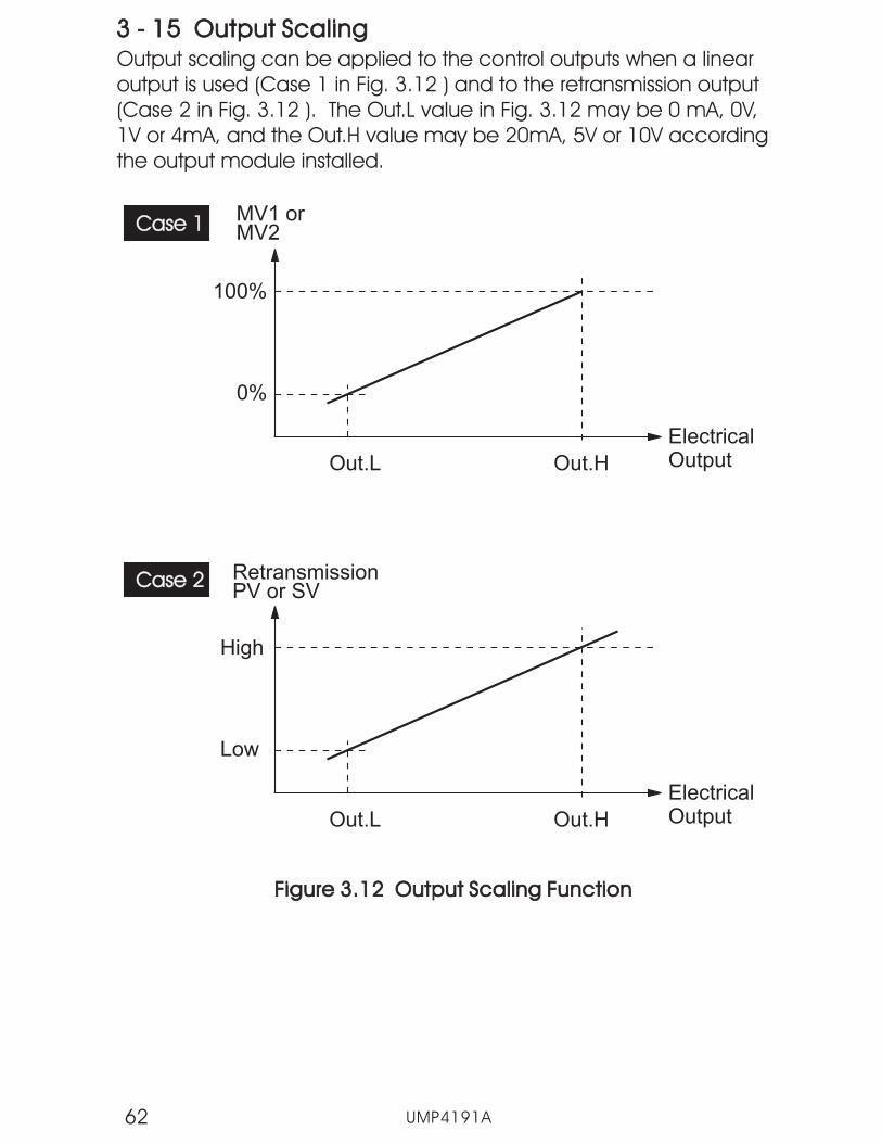
3 - 15 Output Scaling3 - 15 Output ScalingOutput scaling can be applied to the control outputs when a linearoutput is used (Case 1 in Fig. 3.12 ) and to the retransmission output(Case 2 in Fig. 3.12 ). The Out.L value in Fig. 3.12 may be 0 mA, 0V,1V or 4mA, and the Out.H value may be 20mA, 5V or 10V accordingthe output module installed.
0%
MV1 orMV2
ElectricalOutput
100%
Out.L
Case 1Case 1
Out.H
Low
RetransmissionPV or SV
ElectricalOutput
High
Out.L
Case 2Case 2
Out.H
Figure 3.12 Output Scaling FunctionFigure 3.12 Output Scaling Function
UMP4191A62

Chapter 4 Profiler OperationChapter 4 Profiler Operation
4-1 What is a Set Point Profiler4-1 What is a Set Point Profiler
Many applications need to vary temperature or process value with time.Such applications need a controller which varies set point as a functionof time. The P41 and P91 controllers can do this. The set point is variedby using a set point profiler. Profiles are stored as a series of "ramp" and"dwell" segments, as shown below.
Set point
Time
Figure 4.1 Set Point ProfileFigure 4.1 Set Point Profile
In each segment, you can also define the state of up to 3 eventoutputs which can drive either relay, logic or triac outputs dependingon the modules installed in the controller.
A profile can be executed once, or repeated a set number of times oreven repeated continuously. If repeated a set number of times, thenumber of cycles must be specified as part of the profile.
There are four types of segment:
Ramp
The set point ramp (linear), from its current value to anew value, can be at a set rate (ramp rate), or in aset period of time (ramp time). The ramp rate or theramp time and the target set point are specified foreach segment when creating or modifying a profile.
The set point remains constant for a specified period.
It is often necessary to jump backward and run theloop a set number of cycles.
The profile either ends in this segment or repeats aset number of cycles. The profile stops after therepeated cycles are finished.
Dwell
Jump
End
Table 4.1 Segment TypesTable 4.1 Segment Types
UMP4191A 63

4-2 Segment Connection4-2 Segment Connection
Four kinds of combinations are allowable for connecting segments,These are:
Ramp-Ramp:
Ramp-Dwell:
Dwell-Ramp:
Dwell-Dwell:
4-3 Profiler (Control) Modes4-3 Profiler (Control) Modes
The “P” Series controllers have eight operating modes:
Mode Description Indication
RunIn run mode, the profiler varies the set pointaccording to the stored profile values.
Hold
In hold mode, the profile is “frozen” at itscurrent point. In this state you can maketemporary changes to any profileparameter (for example, a target set point,a dwell time or the time remaining in thecurrent segment). Such changes will onlyremain effective until the profile is reset andrun again, when they will be overwritten bythe stored profile values.
RUN light on
HLD light on
UMP4191A64
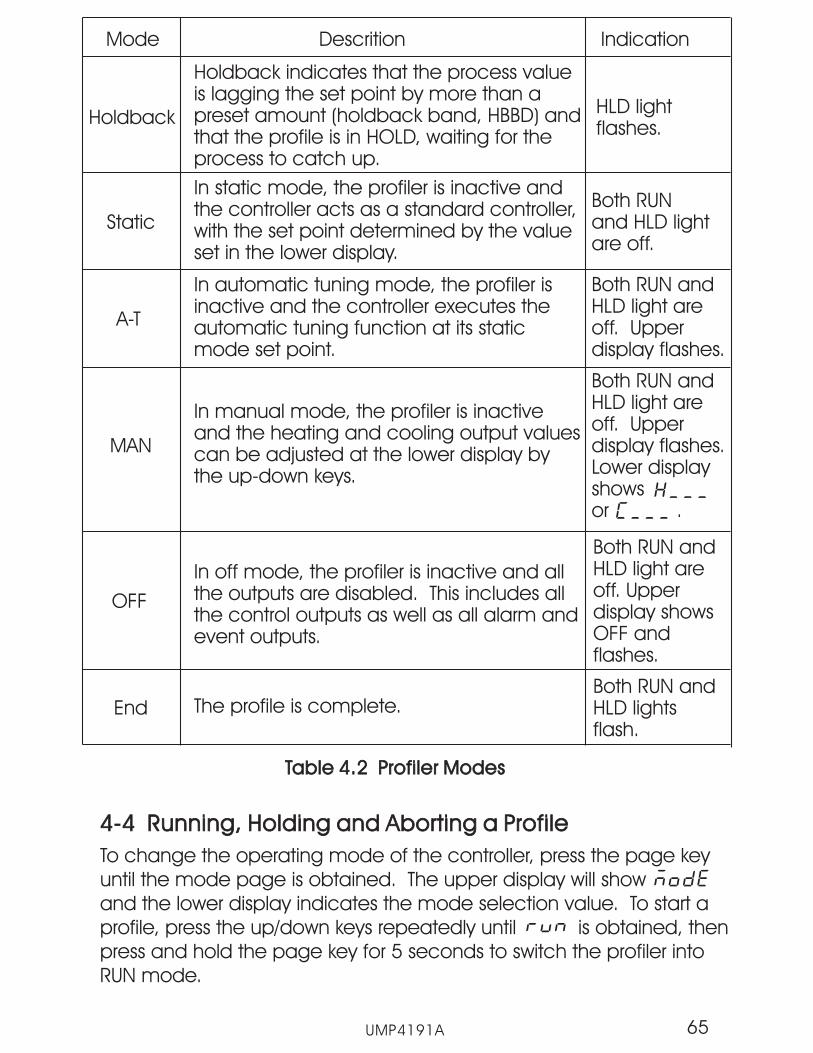
Mode Descrition Indication
Holdback
Holdback indicates that the process valueis lagging the set point by more than apreset amount (holdback band, HBBD) andthat the profile is in HOLD, waiting for theprocess to catch up.
HLD lightflashes.
Static
In static mode, the profiler is inactive andthe controller acts as a standard controller,with the set point determined by the valueset in the lower display.
Both RUNand HLD lightare off.
A-T
In automatic tuning mode, the profiler isinactive and the controller executes theautomatic tuning function at its staticmode set point.
Both RUN andHLD light areoff. Upperdisplay flashes.
MAN
In manual mode, the profiler is inactiveand the heating and cooling output valuescan be adjusted at the lower display bythe up-down keys.
Both RUN andHLD light areoff. Upperdisplay flashes.Lower displayshowsor .
OFF
In off mode, the profiler is inactive and allthe outputs are disabled. This includes allthe control outputs as well as all alarm andevent outputs.
Both RUN andHLD light areoff. Upperdisplay showsOFF andflashes.
End The profile is complete.Both RUN andHLD lightsflash.
Table 4.2 Profiler ModesTable 4.2 Profiler Modes
4-4 Running, Holding and Aborting a Profile4-4 Running, Holding and Aborting a Profile
To change the operating mode of the controller, press the page keyuntil the mode page is obtained. The upper display will showand the lower display indicates the mode selection value. To start aprofile, press the up/down keys repeatedly until is obtained, thenpress and hold the page key for 5 seconds to switch the profiler intoRUN mode.
UMP4191A 65
Once a profile is running, the user can put the profiler in HOLD mode,which “freezes” the profile at its current state. The set point, event outputsand time remaining in the segment will maintain their values unlesschanged by the user or the profiler is put back into RUN mode. To placethe profiler in HOLD, select from the mode page, and press andhold the page key for 5 seconds. The profiler will then enter HOLD mode.
The operator may also abort (i.e., terminate) the profile by selecting(static mode) from the mode page. When the program is aborted, theprofiler is inactive and enters static mode. At the same time both the RUNlight and HLD light are off.
4-5 Viewing and Modifying Profile Operation4-5 Viewing and Modifying Profile Operation
Three parameters: PFSG, TIME and CYCL indicate the status of profileprogress. The operator can easily view these parameters, the currentprofile and segment number, the time remaining for the current segmentand the cycles remaining for the current profile, on the home page bypressing the scroll key and cycling through the values.
By changing the value of (profile and segment number) using theup/down keys, the user can select a desired profile/segment entry pointto start or jump the current segment to the next segment when in HOLDmode. When in HOLD mode, the user can also change the value of TIMEto shorten or prolong the time remaining of the current segment. If itis determined that additional cycles are required of the current profile,the CYCL parameter can be changed to increase or decrease thenumber of jumps remaining.
4-6 Profile Start Options4-6 Profile Start Options
When a profile is started, the set point can start from either the currentprocess value, the last control set point or from a predefined starting setpoint. The parameter is used to specify this starting set point value.
selects the process value (default value)selects the current controller set point valueselects the start set point value
The normal method is to start from the process value, because this willproduce a smooth and bumpless start to the process. However, if thetime period of the first segment must be defined, using SP1or STSP for thestarting point will insure that the first segment time duration is maintained.
STAR
PV:
SP1:
STSP:
STAR
UMP4191A66
As the set point ramps up or down (or dwells), the measured value maylag behind or deviate from the set point by an undesirable amount."Holdback" is available to freeze the profile at its current state, should thisoccur. The action of Holdback is similar to a deviation alarm and can be
enabled or disabled on a per segment basis. Holdback uses threeparameters: - holdback wait time, - holdback band and
- holdback type.
If the deviation from the set point exceeds the holdback band (HBBD),then the holdback feature, if enabled, will automatically freeze theprofile at its current point and the HLD light will flash to indicateholdback is active. At the same time, the holdback timer begins tocount. When the value of the holdback timer exceeds the value ofholdback wait time , the profiler will automatically terminate theholdback and jump to the next segment. When this occurs, an errorcode will be displayed on the controller to indicate that theholdback wait time had been exceeded.
If the process value returns to within the holdback band setting beforethe holdback timer is exceeded, the profile will resume operation asnormal. There are four different Holdback types:
HBT HBBD
HBTY
HBT
- Disables Holdback - no action is taken.- Deviation Low Holdback holds the profile back when the
process value deviates below the set point by more then theholdback band (HBBD).
- Deviation High Holdback holds the profile back when theprocess value deviates above the set point by more than theholdback band (HBBD).
- Deviation Band Holdback is a combination of the two. Itholds the profile back when the process value deviates eitherabove or below the set point by more than the holdbackband (HBBD).
UMP4191A 67
4-7 Holdback4-7 Holdback
NOTE
HBT
HBBD
HBTY
is a global parameter which is common to all profiles.is a parameter which applies to a specific profile.
is a parameter which applies to a segment in a specific profile.
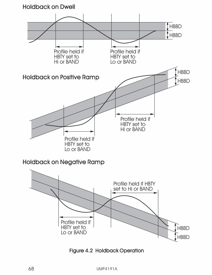
Profile held ifHBTY set toLo or BAND
Profile held ifHBTY set toHi or BAND
HBBD
HBBDHoldback on Positive RampHoldback on Positive Ramp
Profile held ifHBTY set toLo or BAND
Profile held if HBTYset to Hi or BAND
HBBD
HBBD
Holdback on Negative RampHoldback on Negative Ramp
Profile held ifHBTY set toHi or BAND
Profile held ifHBTY set toLo or BAND
HBBD
HBBD
Holdback on DwellHoldback on Dwell
Figure 4.2 Holdback OperationFigure 4.2 Holdback Operation
UMP4191A68

4-8 Power Failure4-8 Power Failure
If power is lost to the controller and then restored while a profile isrunning, the behavior of the profile is determined by the setting of thepower failure recovery parameter "PFR" in the profile configuration.There are 4 available settings - , , and .
If is selected, then when power is restored, the profile continuesfrom where it was interrupted when power was lost. The set point value(SV), time remaining (TIME) and cycles remaining (CYCL) will be restoredto their power-down values. This selection provides the fastest processrecovery. The following figures (4.3 and 4.4) show the recovery actionwhen continue is selected.
Figure 4.3 Recovery from Profile at Dwell SegmentFigure 4.3 Recovery from Profile at Dwell Segment
Figure 4.4 Recovery from Profile at Ramp SegmentFigure 4.4 Recovery from Profile at Ramp Segment
Set pointSet point
Time
power onpower on
power offpower off
Ramp Segment Dwell Segment
Target Set pointTarget Set point
UMP4191A 69
Set pointSet point
Time
t1
Segment dwelltime = t1+t2Segment dwelltime = t1+t2
power offpower off
power onpower on
t2
RampSegment Dwell Segment

If is selected, then when power is restored the set point starts atthe current process value, and then ramps to the target set point of theactive segment within the remaining segment time. This choiceprovides a smoother recovery. The two figures below illustrate therespective recovery responses.
Figure 4.5 Recovery from PV at Dwell SegmentFigure 4.5 Recovery from PV at Dwell Segment
Figure 4.6 Recovery from PV at Ramp SegmentFigure 4.6 Recovery from PV at Ramp Segment
Set pointSet point
Time
power onpower on
power offpower off
Ramp Segment Dwell Segment
Target Set pointTarget Set point
If is selected, when power is restored, the profiler is disabledand the controller enters static mode. SP1 is used for the control setpoint.
If is selected, when power is restored, the profiler is disabledand the controller enters OFF mode. All the control outputs as well asalarm and event outputs are turned off.
UMP4191A70
RampSegment
Set pointSet point
Time
t1
Segment dwelltime = t1+t2Segment dwelltime = t1+t2
power offpower off
power onpower on
t2
DwellSegment

4-9 Configuring the Profiler4-9 Configuring the Profiler
Prior to creating a profile or using the controller for the first time, youshould familiarize yourself with all of the profile parameters and settings,and insure that the controller is configured properly for your application.
STAR:END:DLAY:PFR:HBT:
Global DataGlobal Data
The following parameters are common to all profiles (configuration):
PROF:HBBD:STSP:RMPU:DLLU:
Profile DataProfile Data
The following parameters apply to a specific profile:
SGNO:SGTY:TGSP:RTRR:P2EV:HBTY:DLLT:SEG:CYCL:FSP:
Segment DataSegment Data
The following parameters apply to each segment of a specific profile:
UMP4191A 71
set point value at start of profileset point value at end of profiledelay time before profile startpower fail recoveryholdback wait time
profile number selected for viewholdback bandstart set point valueunit for ramp segmentunit for dwell segment
segment numbersegment typetarget set pointramp time or ramp ratePID selection and event output statesholdback typedwell timetarget segment number for jump segmentrepeat number of cyclefinal set point for the end segment
4-10 Viewing and Creating a Profile4-10 Viewing and Creating a Profile
To create or view a profile stored in the unit, press the page keyrepeatedly in order to get to the profile page. The profile page will beindicated by in the upper display, and the lower display willindicate the number of the currently selected profile (1-9).

UMP4191A72
Using the up/down keys, enter the number of the profile to be viewedor edited. Once the selection is made, pressing the scroll key will thencycle through the profile data and segment parameter values (see
, ).
The profile data values include the holdback band ( ), the startset point ( ), the ramp units ( ) and the dwell units ( ).If holdback is going to be required for the profile, set the holdback bandto the allowed maximum deviation that will be allowed from set pointduring profile operation. Note that the holdbank band is entered inwhole numbers only, regardless of the decimal point selection made forthe input configuration of the control.
If the profile start set point has been selected in the configuration as thestart set point for profiles, set the start set point to the required value forthe profile. Next, set the ramp and dwell units to the desired setting forthe profile. Note that these settings apply to all ramp and dwell segmentsof the profile. The available selections are:
Ramp Segments
Section 1-5 Key Operation Flowchart
= hours : minutes= minutes : seconds= ramp rate in units per minute= ramp rate in units per hour
= hours : minutes= minutes : seconds
Dwell Sgements
The next parameter after the profile data values is the segment number( ). This is the first of the segment parameters and is used to selectwhich segment of the profile is to be viewed/edited. The value can bechanged using the up/down arrow keys from 0 (first step of the profile) tothe last step of the selected profile.
Pressing the scroll key repeatedly will cycle through the availablesegment parameters. The display will then automatically return to thesegment number parameter once all other parameters have been setfor a segment, in order to speed profile entry. This allows the user tosimply set the next segment number of the profile and then scrollthrough and edit its associated values.
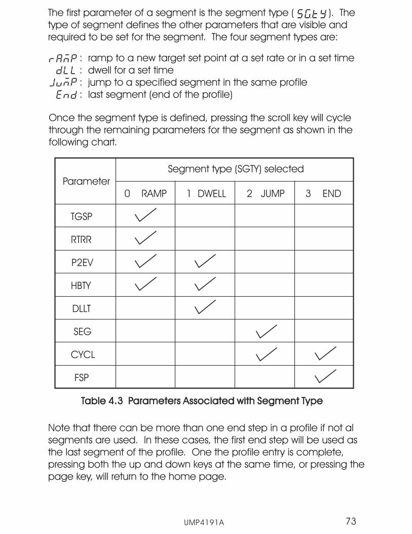
UMP4191A 73
: ramp to a new target set point at a set rate or in a set time: dwell for a set time: jump to a specified segment in the same profile: last segment (end of the profile)
The first parameter of a segment is the segment type ( ). Thetype of segment defines the other parameters that are visible andrequired to be set for the segment. The four segment types are:
Parameter
Segment type (SGTY) selected
0 RAMP 1 DWELL 2 JUMP 3 END
TGSP
RTRR
P2EV
HBTY
DLLT
SEG
CYCL
FSP
Table 4.3 Parameters Associated with Segment TypeTable 4.3 Parameters Associated with Segment Type
Note that there can be more than one end step in a profile if not alsegments are used. In these cases, the first end step will be used asthe last segment of the profile. One the profile entry is complete,pressing both the up and down keys at the same time, or pressing thepage key, will return to the home page.
Once the segment type is defined, pressing the scroll key will cyclethrough the remaining parameters for the segment as shown in thefollowing chart.

UMP4191A74
0 15
32
5
35
34
5
55
36
5
65
37
5
90
40
0
11
0
42
0
13
0
44
0
14
0
45
0
16
5
47
5
18
9
49
9
21
9
52
9
24
9
55
9
27
9
58
9
29
9
60
9
31
0
62
0
25
150
250
450
650
1 1
22
3 3
4 4
5 51 1
2 2
3 3
4 4
5 56 6
7 7
8 8
9 9
10 10
11 11
END
Event 1
Event 2
Event 3(End of Profile)
PID 2
Time (minutes)
Figure 4.7 Profile ExampleFigure 4.7 Profile Example
0
12 12
Set point
0100
A heat treatment oven needs to vary temperature as a function of timeaccording to the process graph depicted above. Output 1 of thecontrol is used as the heating output, but due to the high rate of heatingrequired, an additional heater is turned on at elevated temperaturesusing event 1 (output 2) to act as a boost. When the boost heater isactivated, a second PID set is also required in order to maintain propertemperature control of the oven.
In order to accelerate cooling, a fan is turned on through event 2(output 3) during the cooling sequences. In order to alert operators thatthe profile has completed, an alarm is connected to output 4 (event 3)of the P41 controller. This is turned on for the last segment of the profileto indicate that the process is complete.

UMP4191A 75
Global DataGlobal Data
STAR = STSPEND = OFFDLAY = 0PFR = PVHBT = 1.00
Profile DataProfile Data
PROF = 1HBBD = 50STSP = 25.0RMPU = HH.MMDLLU = HH.MM
SGNO = 0SGTY = RAMPTGSP = 150.0RTRR = 00.15P2EV = 0000HBTY = Lo
SGNO = 1SGTY = DLLP2EV = 0000HBTY = bandDLLT = 00.20
SGNO = 2SGTY = RAMPTGSP = 250.0RTRR = 00.20P2EV = 0000HBTY = Lo
SGNO = 3SGTY = DLLP2EV = 0000HBTY = bandDLLT = 00.10
SGNO = 4SGTY = RAMPTGSP = 150.0RTRR = 00.25P2EV = 0001HBTY = Hi
Segment DataSegment Data
Segment 0
Segment 1
Segment 2
Segment 3
Segment 4
SGNO = 5SGTY = JUMPSEG = 1CYCL = 2
SGNO = 6SGTY = DLLP2EV = 0000HBTY = bandDLLT = 00.24
SGNO = 7SGTY = RAMPTGSP = 650.0RTRR = 00.30P2EV = 1010HBTY = Lo
SGNO = 8SGTY = DLLP2EV = 1010HBTY = bandDLLT = 00.30
SGNO = 9SGTY = RAMPTGSP = 450.0RTRR = 00.30P2EV = 1011HBTY = Hi
Segment 5
Segment 6
Segment 7
Segment 8
Segment 9
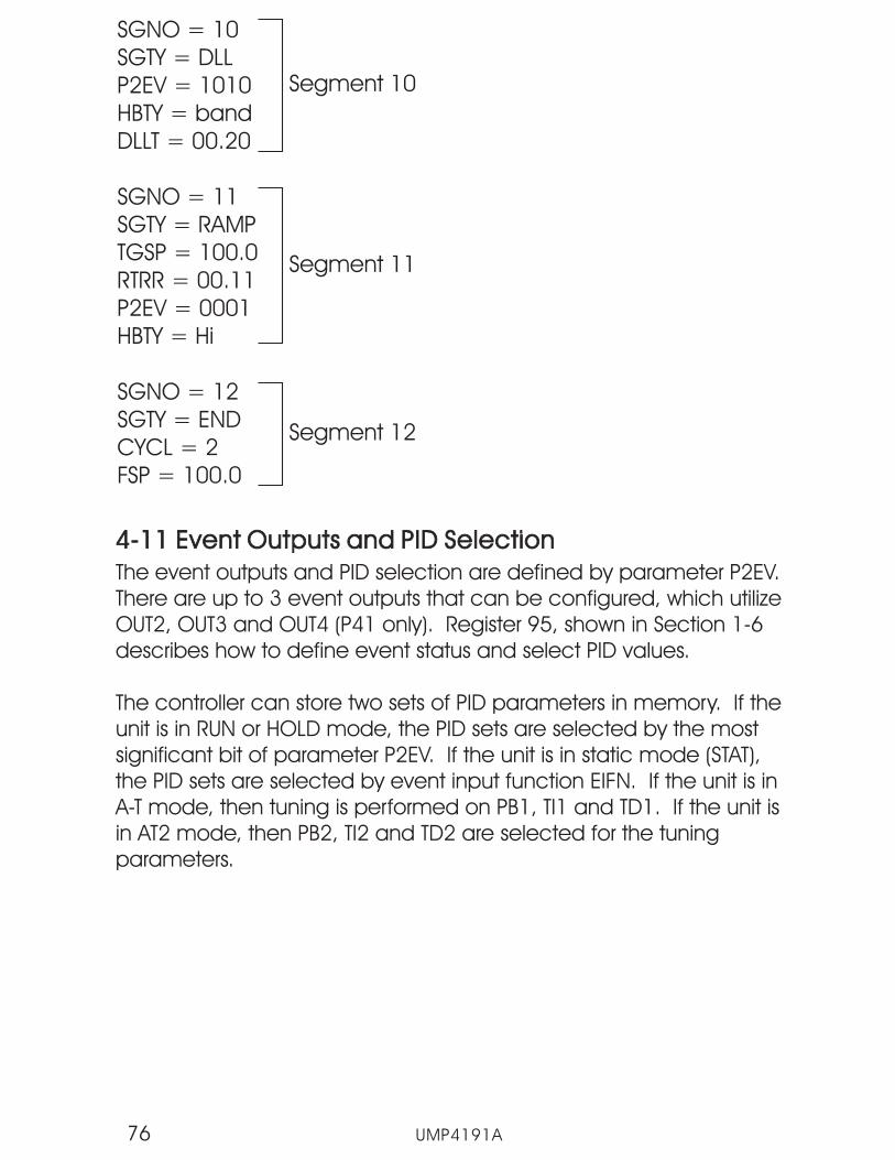
UMP4191A76
SGNO = 10SGTY = DLLP2EV = 1010HBTY = bandDLLT = 00.20
SGNO = 11SGTY = RAMPTGSP = 100.0RTRR = 00.11P2EV = 0001HBTY = Hi
SGNO = 12SGTY = ENDCYCL = 2FSP = 100.0
Segment 10
Segment 11
Segment 12
4-11 Event Outputs and PID Selection4-11 Event Outputs and PID Selection
The event outputs and PID selection are defined by parameter P2EV.utilize
OUT2, OUT3 and OUT4 (P41 only). Register 95, shown in Section 1-6describes how to define event status and select PID values.
The controller can store two sets of PID parameters in memory. If theunit is in RUN or HOLD mode, the PID sets are selected by the mostsignificant bit of parameter P2EV. If the unit is in static mode (STAT),the PID sets are selected by event input function EIFN. If the unit is inA-T mode, then tuning is performed on PB1, TI1 and TD1. If the unit isin AT2 mode, then PB2, TI2 and TD2 are selected for the tuningparameters.
There are up to 3 event outputs that can be configured, which
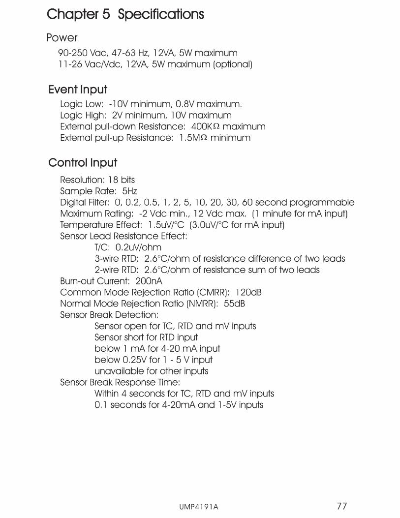
UMP4191A 77
Chapter 5 SpecificationsChapter 5 Specifications
Power
Control InputControl Input
90-250 Vac, 47-63 Hz, 12VA, 5W maximum11-26 Vac/Vdc, 12VA, 5W maximum (optional)
Resolution: 18 bitsSample Rate: 5HzDigital Filter: 0, 0.2, 0.5, 1, 2, 5, 10, 20, 30, 60 second programmableMaximum Rating: -2 Vdc min., 12 Vdc max. (1 minute for mA input)Temperature Effect: 1.5uV/°C (Sensor Lead Resistance Effect:
T/C: 0.2uV/ohm3-wire RTD: 2.6°C/ohm of resistance difference of two leads2-wire RTD: 2.6°C/ohm of resistance sum of two leads
Burn-out Current: 200nACommon Mode Rejection Ratio (CMRR): 120dBNormal Mode Rejection Ratio (NMRR): 55dBSensor Break Detection:
3.0uV/°C for mA input)
Sensor open for TC, RTD and mV inputsSensor short for RTD inputbelow 1 mA for 4-20 mA inputbelow 0.25V for 1 - 5 V inputunavailable for other inputs
Sensor Break Response Time:Within 4 seconds for TC, RTD and mV inputs0.1 seconds for 4-20mA and 1-5V inputs
Event InputEvent Input
Logic Low:Logic High:External pull-down Resistance:External pull-up Resistance:
-10V minimum, 0.8V maximum.2V minimum, 10V maximum
400K maximum1.5M minimum

UMP4191A78
Characteristics:
Type RangeInput
ImpedanceInput
Impedance
J-120°C - 1000°C(-184°F - 1832°F)-120°C - 1000°C(-184°F - 1832°F)
Accuracy@ 25 CAccuracy@ 25 C
K-200°C - 1370°C
(-328°F - 2498°F )-200°C - 1370°C
(-328°F - 2498°F )
-250°C - 400°C(-418°F - 752°F)-250°C - 400°C(-418°F - 752°F)
-100°C - 900°C(-148°F - 1652°F)-100°C - 900°C
(-148°F - 1652°F)
0°C - 1800°C(32°F - 3272°F)0°C - 1800°C
(32°F - 3272°F)
0°C - 1767.8°C(32°F - 3214°F)0°C - 1767.8°C(32°F - 3214°F)
T
E
B
2.2 M2.2 M
2.2 M2.2 M
2.2 M2.2 M
2.2 M2.2 M
2.2 M2.2 M
2.2 M2.2 M
2.2 M2.2 M
2.2 M2.2 M
2.2 M2.2 M
2.2 M2.2 M
PT100( DIN )PT100( DIN )
(200°C -1800°C)
(200°C -1800°C)
2°C
2°C
2°C
2°C
2°C
0.4°C
0.4°C
0.05%
-250°C - 1300°C(-418°F - 2372°F)-250°C - 1300°C(-418°F - 2372°F)
-200°C - 900°C(-328°F - 1652°F)-200°C - 900°C
(-328°F - 1652°F)
-200°C - 600°C(-328°F - 1112°F)-200°C - 600°C
(-328°F - 1112°F)
R
S
N
L
PT100( JIS )PT100( JIS )
mV
mA
V
-210°C - 700°C(-346°F - 1292°F)-210°C - 700°C
(-346°F - 1292°F)
-8mV - 70mV-8mV - 70mV
-3mA - 27mA-3mA - 27mA
-1.3V - 11.5V-1.3V - 11.5V
0.05%
0.05%
70.5
650 K650 K
1.3 K1.3 K
1.3 K1.3 K
2.2 M2.2 M
2.2 M2.2 M
0°C - 2315°C(32°F - 4199°F)0°C - 2315°C
(32°F - 4199°F)C
P0°C - 1395°C
(32°F - 2543°F)0°C - 1395°C
(32°F - 2543°F)
2°C
2°C
2°C
2°C
2°C
2°C
0°C - 1767.8°C(32°F - 3214°F)0°C - 1767.8°C(32°F - 3214°F)
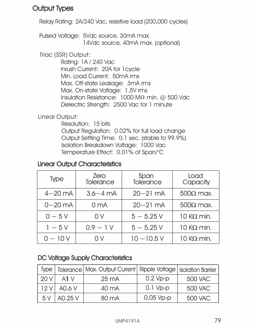
UMP4191A 79
Output TypesOutput Types
Relay Rating: 2A/240 Vac, resistive load (200,000 cycles)
Pulsed Voltage: 5Vdc source, 30mA max.14Vdc source, 40mA max. (optional)
Linear Output CharacteristicsLinear Output Characteristics
Type ZeroTolerance
ZeroTolerance
SpanTolerance
SpanTolerance
LoadCapacity
LoadCapacity
4~20 mA4~20 mA 3.6~4 mA3.6~4 mA 20~21 mA20~21 mA
20~21 mA20~21 mA
500 max.�500 max.�
500 max.�500 max.�0~20 mA0~20 mA 0 mA0 mA
0 V0 V
0 V0 V
10 K min.�10 K min.�
10 K min.�10 K min.�
10 K min.�10 K min.�
0 ~ 5 V0 ~ 5 V
0.9 ~ 1 V0.9 ~ 1 V
5 ~ 5.25 V5 ~ 5.25 V
5 ~ 5.25 V5 ~ 5.25 V
10 ~10.5 V10 ~10.5 V
1 ~ 5 V1 ~ 5 V
0 ~ 10 V0 ~ 10 V
Resolution: 15 bitsOutput Regulation: 0.02% for full load changeOutput Settling Time: 0.1 sec. (stable to 99.9%)Isolation Breakdown Voltage: 1000 VacTemperature Effect: 0.01% of Span/°C
Linear Output:
Triac (SSR) Output:
Rating: 1A / 240 VacInrush Current: 20A for 1cycleMin. Load Current: 50mA rmsMax. Off-state Leakage: 3mA rmsMax. On-state Voltage: 1.5V rmsInsulation Resistance: 1000 M min. @ 500 VdcDielectric Strength: 2500 Vac for 1 minute
DC Voltage Supply CharacteristicsDC Voltage Supply Characteristics
Type Tolerance Max. Output CurrentMax. Output Current Ripple VoltageRipple Voltage Isolation Barrier
20 V20 V A V1A V1 25 mA25 mA 0.2 Vp-p0.2 Vp-p 500 VAC500 VAC
500 VAC500 VAC
500 VAC500 VAC
12 V12 V A0.6 VA0.6 V 40 mA40 mA 0.1 Vp-p0.1 Vp-p
5 V5 V A0.25 VA0.25 V 80 mA80 mA 0.05 Vp-p0.05 Vp-p

UMP4191A80
Data CommunicationData Communication
Interface: RS-232 (1 unit), RS-485 (up to 247 units)Protocol: Modbus RTUAddress: 1-247Baud Rate: 2.4 ~ 38.4 Kbits/secParity: None, Even or OddCommunication Buffer: 256 bytes
Output Signal: 4-20mA, 0-20mA, 0-5V, 1-5V, 0-10VResolution: 15 bitsAccuracy: 0.05% of spanLoad Resistance:
0 - 500 ohms (for current output)10 K ohms minimum (for voltage output)
Output Regulation: 0.01% for full load changeIsolation Breakdown Voltage: 1000 VAC min.
Output Settling Time: 0.1 sec. (stable to 99.9%)Integral Linearity Error: 0.005% of spanTemperature Effect: 0.0025% of span/°CSaturation Low: 0mA (or 0V)Saturation High: 22.2 mA (or 5.55V, 11.1V min.)Linear Output Range:
0-22.2mA (0-20mA or 4-20mA)0-5.55V (0-5V, 1-5V)0-11.1V (0-10V)
Analog RetransmissionAnalog Retransmission
Profiler
Number of Profiles: 9Number of Segments per Profile:
Profile 1 ~ 4: 16Profile 5 ~ 7: 32Profile 8, 9: 64
Event Outputs: 3 maximum (2 for P91)

UMP4191A 81
User InterfaceUser Interface
Dual 4-digit LED DisplaysKeypad: 4 keysProgramming Port: automatic setup, calibration and testingCommunication Port: RS-232 or RS-485 (Modbus RTU protocol)
Control ModeControl Mode
Output 1: Reverse (heating) or direct (cooling) actionOutput 2: Event 1or alarm 1, PID cooling control; cooling P band
50~300% of PB, dead band -36.0 ~ 36.0% of PBOutput 3: Event 2 or alarm 2Output 4: Event 3 or alarm 3 (P41 only)ON-OFF: 0.1-90.0 (°F) hysteresis control (P band = 0)P or PD: 0-100.0% offset adjustmentPID: Fuzzy logic modified
Proportional band 0.1 ~ 900.0°F.Integral time 0-1000 secondsDerivative time 0-360.0 seconds
Cycle Time: 0.1-90.0 secondsManual Control: Heat (MV1) and Cool (MV2)Auto-tuning: Cold start and warm startFailure Mode: Auto-transfer to manual mode for sensor break or
A-D converter failureRamping Control: 0-900.0 °F/minute or 0-900.0°F/hour ramp rate
Alarm
Alarm Functions: Dwell timer, deviation high/low, deviation band,PV high/low alarm
Alarm Mode: Normal, latching, hold, latching/holdDwell Timer: 0.1-4553.6 seconds

UMP4191A82
Approval StandardsApproval Standards
UL Listed
CSA
CE
RoHS
EMC
File E197216File 209463
EN61010-1 (IEC1010-1)
En61326
Environmental & PhysicalEnvironmental & Physical
Operating Temperature: -10°C to 50°CStorage Temperature: -40°C to 60°CHumidity: 0 to 90% RH (non-condensing)Altitude: 2000m maximumPollution: Degree 2Insulation Resistance: 20 Mohms min. (at 500 VDC)Dielectric Strength: 2000 VAC, 50/60 Hz for 1 minuteVibration Resistance: 10 - 55 Hz, 10 m/s for 2 hoursShock Resistance: 200 m/s (20g)Moldings: Flame retardant polycarbonateDimensions:
P41 ----- 96mm(W) X 96mm(H) X 65mm(D),53 mm depth behind panel
P91 ----- 48mm(W) X 48mm(H) X 116mm(D),105 mm depth behind panel
Weight:P41 ----- 250 gramsP91 ----- 150 grams
2
2
Protective Class :
EMC:
IP65 for panel with additional optionIP50 for panel without additional optionIP20 for terminals and housing with protective cover.All indoor use only.
En61326

UMP4191A 83
Table A.1 Error Codes and Corrective ActionsTable A.1 Error Codes and Corrective Actions
ErrorCode
DisplaySymbol Error Description Corrective Action
Illegal setup values been used:Before COOL is used for OUT2,DIRT (cooling action) hasalready been used for OUT1, orPID mode is not used for OUT1(that is PB = 0, and/or TI = 0 )
4
Communication error: badfunction code10
Correct the communicationsoftware to meet the protocolrequirements.
Communication error: registeraddress out of range11
Don't issue an over-rangeaddress to the slave.register
Communication error: attemptto write a read-only data or aprotected data
14
Don't write a read-only data or aprotected data to the slave.
Communication error: write avalue which is out of range to aregister
15
Don't write an over-range datato the slave register.
26Fail to perform auto-tuning
function
EEPROM can't be written correctly29 Return to factory for repair.
Input sensor break, or inputcurrent below 1 mA if 4-20 mA isselected, or input voltage below0.25V if 1 - 5V is selected
39 Replace input sensor.
40A to D converter or relatedcomponent(s) malfunction
Return to factory for repair.
Check and correct setup valuesof OUT2, PB, TI and OUT1. If OUT2is required for cooling control, thecontrol should use PID mode (PB= 0, TI = 0 ) and OUT1 shoulduse reverse mode (heat action),otherwise, don't use OUT2 forcooling control.
1. The PID values obtained afterauto-tuning procedure are outof range. Retry auto-tuning.
2. Don't change set point valueduring auto-tuning procedure.
3. Use manual tuning instead ofauto-tuning.
5. Don’t set a zero value for TI.
4. Don't set a zero value for PB.
6. Touch RESET key
Cold junction compensation for
thermocouple malfunction30 Return to factory for repair.
Appendix A-1Appendix A-1
Holdback time out25
You have selected an input typewhich was not calibrated
Evaluate validity of the PID values
Calibrate the new input type orchange input type to thecalibrated one.
27

UMP4191A84
Appendix A-2Appendix A-2
Future Design Controls products shown below are warrantied to be free from functional defects in materials andworkmanship at the time the products leave Future Design Controls facilities and to conform at that time to thespecifications set forth in the relevant Future Design Controls manual, sheet or sheets for a period of afterthe delivery to the first purchaser for use.
FDC-2500, 9300, 8300, 4300FDC-9100, 8100, 4100, C91, C21, L91, L41 and B41FDC -P91 and P41FDC-9090, 8120, 8130, 4120, 2220, 9200
Future Design Controls provides no warranty or representations of any sorts regarding the fitness of use or application ofits product by the purchaser. Users are responsible for the selection, suitability of the products for their application or useof Future Design Controls products.
Future Design Controls shall not be liable for any damages or losses, whether direct, indirect, incidental, special,consequential or any other damages, costs or expenses excepting only the cost or expense of repair or replacementof the Future Design Control products as described below.
Future Design Controls sole responsibility under warranty, at Future Design Controls option, is limited to replacement orrepair, free of charge, or refund of purchase price within the warranty period specified. This warranty does not apply tdamage resulting from transportation, alteration, misuse or abuse.
Future Design Controls reserves the right to make changes without notification to purchaser to materials or processingthat do not affect compliance with any applicable specifications.
Please contact Future Design Controls for Return Material Authorization Number prior to returning to factory.
Future Design Controls7524 West 98th PlaceBridgeview,IL 60455Main Office Phone - 888-751-5444
Fax - 888-307-8014Technical Support
Phone - 866-342-5332Www.futuredesigncontrols.comE-mail; [email protected]
Three years
300 Series:
100/C/L/B Series:
P Series:
90 & 200 Series:
RETURN MATERIAL AUTHORIZATION:
Warranty