p1010 chip errata - digi-key · a-003571 multiple read/write ... fail to complete the enumeration...
TRANSCRIPT
This document details all known silicon errata for the P1010. The following table provides a revision history forthis document.
Table 1. Document Revision History
Revision Date Significant Changes
L 04/2013 • Added SEC erratum A-005455• Added USB errata A-004477, A-005375, A-005696, A-005728• Modified PCIe erratum A-004761
K 03/2013 • Added CPU erratum A-006184• Added eSDHC errata A-004388 and A-006414• Added PCIe errata A-004033, A-004409, and A-005754• Added SATA erratum A-005820• Added SEC errata A-005345, A-005403, A-005445, A-005447, A-005467, A-005470,
A-005473, A-005487, A-005714, A-005787, and A-006385• Added USB errata A-003832, A-003834, A-003836, A-003838, A-003840, A-003842,
A-003843, A-003844, A-003845, A-003846, A-003848, A-003849, A-003850,A-005451, A-005511, and A-005697
J 01/2013 • Added SATA erratum A-005035• Added USB erratum A-003829• Added I2C erratum A-006037
H 11/2012 • Added SATA errata A-005636 and A-005637• Added USB erratum A-005275• Modified PCIe erratum A-004761
G 09/2012 • Added USB erratum A-003837 and A-003817• Added I2C erratum A-004447• Added eSDHC erratum A-005055
F 07/2012 • Added PCIe erratum A-004761• Added DDR erratum A-004508• Added CPU erratum A-005125• Updated CPU erratum A-003477• Updated CPU erratum A-001428• Renamed DUART 1 to A-004737• Sorted errata within category
E 02/2012 • Added A-004373• Modified A-003477
Table continues on the next page...
Freescale Semiconductor P1010CE
Chip Errata Rev. L, 04/2013
P1010 Chip Errata
© 2013 Freescale Semiconductor, Inc.Freescale Confidential Proprietary - Non-Disclosure Agreement required

Table 1. Document Revision History (continued)
Revision Date Significant Changes
D 12/2011 • Added A-003477• Modified USB-A001 and A-003549• Removed USB-A005, USB-A007, USB 10, USB 9, USB 6, and USB 5, as these are
moved to the "USB Serial Bus Interface" chapter of P1010 QorIQ Integrated ProcessorReference Manual, Rev. 0.
C 07/2011 • Added USB-A007, A-003480, A-003571, A-003399, A-003549, A-002770, andA-002769
• Removed USB37
• Modified USB-A001 and CPU 2
B 04/2011 • Added A-001428(CPU-A005) and USB-A005
• Removed IEEE1588-A001
A 08/2010 • Initial release
The following table provides a cross-reference to match the revision code in the processor version register to therevision level marked on the device.
Table 2. Revision Level to Part Marking Cross-Reference
Part Revision ProcessorVersion Register
Value
System Version RegisterValue
Note
P1010E 1.0 0x80212151 0x80F90010 With Security
P1010 1.0 0x80212151 0x80F10010 Without Security
P1014E 1.0 0x80212151 0x80F90110 With Security
P1014 1.0 0x80212151 0x80F10110 Without Security
Table 3 summarizes all known errata and lists the corresponding silicon revision level to which they apply. A ‘Yes’entry indicates the erratum applies to a particular revision level, and an ‘No’ entry means it does not apply.
Table 3. Summary of Silicon Errata and Applicable Revision
Errata Name Projected Solution SiliconRev.
1.0
CPU
A-005125 In a very rare condition, a system hang is possible when the e500core initiates a guarded load to PCI/PCIe/sRIO while the PCI/PCIe/sRIO performs a coherent write to memory.
No plans to fix Yes
Table continues on the next page...
P1010 Chip Errata, Rev. L, 04/2013
2 Freescale Semiconductor, Inc.Freescale Confidential Proprietary - Non-Disclosure Agreement required

Table 3. Summary of Silicon Errata and Applicable Revision (continued)
Errata Name Projected Solution SiliconRev.
1.0
CPU 1 "mbar MO = 1" instruction fails to order caching-inhibited guardedloads and stores
No plans to fix Yes
CPU 2 Single-precision floating-point zero value may have the wrong sign No plans to fix Yes
A-001428 Enabling IEEE 754 exceptions can cause errors No plans to fix Yes
A-003477 Phantom branches in the BTB may not be correctly invalidated No plans to fix Yes
A-006184 Simultaneous Instruction L1 MMU (I-L1VSP) miss (due to eviction)and interrupt servicing can cause a core hang
To be fixed in rev 2.0 Yes
DDR
DDR 8 Memory controller perfmon counter for read beats is inaccurate No plans to fix Yes
A-004508 DDR controller may not function across the full industrial temperaturerange
No plans to fix Yes
DUART
A-004737 BREAK detection triggered multiple times for a single breakassertion
No plans to fix Yes
eSDHC
A-004373 Host may not detect SD card insertion/removal using DAT3 signal No plans to fix Yes
A-005055 A glitch is generated on the card clock with software reset or a clockdivider change
No plans to fix Yes
A-004388 eSDHC DMA might not stop if error occurs on system transaction No plans to fix Yes
A-006414 Reading the DATPORT register while a DMA mode transaction is inprogress may hang the system
No plans to fix Yes
eTSEC
eTSEC 4 VLAN Insertion corrupts frame if user-defined Tx preamble enabled No plans to fix Yes
eTSEC 8 Half-duplex collision on FCS of Short Frame may cause Tx lockup No plans to fix Yes
eTSEC 9 Magic Packet Sequence Embedded in Partial Sequence NotRecognized
No plans to fix Yes
eTSEC 11 VLAN extraction with shim header not supported No plans to fix Yes
eTSEC-A002 Incomplete GRS or invalid parser state after receiving a 1- or 2-byteframe
No plans to fix Yes
GEN
A-003549 Peripheral connected to IFC_CS3 may hamper booting from IFC No plans to fix Yes
A-003571 Multiple read/write transactions initiated by Security engine maycause the device hang
To be fixed in rev 2.0 Yes
I2C
A-004447 Nine SCL pulses cannot be generated when SDA is held low with thesequence provided in documentation
No plans to fix Yes
A-006037 I2C could hang if disabled after enabling in multi-master system No plans to fix Yes
IFC
A-002769 NOR-FCM does not support access to unaligned addresses for 16-bit port size
No plans to fix Yes
A-002770 False ECC error generation in NAND-FCM. No plans to fix Yes
Table continues on the next page...
P1010 Chip Errata, Rev. L, 04/2013
Freescale Semiconductor, Inc. 3Freescale Confidential Proprietary - Non-Disclosure Agreement required
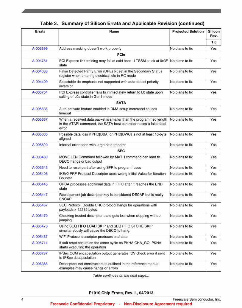
Table 3. Summary of Silicon Errata and Applicable Revision (continued)
Errata Name Projected Solution SiliconRev.
1.0
A-003399 Address masking doesn’t work properly No plans to fix Yes
PCIe
A-004761 PCI Express link training may fail at cold boot - LTSSM stuck at 0x3Fstate
No plans to fix Yes
A-004033 False Detected Parity Error (DPE) bit set in the Secondary Statusregister when entering electrical idle in RC mode
No plans to fix Yes
A-004409 Selectable de-emphasis not supported with auto-detect polarityinversion
No plans to fix Yes
A-005754 PCI Express controller fails to immediately return to L0 state uponexiting of L0s state in Gen1 mode
No plans to fix Yes
SATA
A-005636 Auto-activate feature enabled in DMA setup command causestimeout
No plans to fix Yes
A-005637 When a received data packet is smaller than the programmed lengthin the ATAPI command, the SATA host controller raises a false fatalerror
No plans to fix Yes
A-005035 Possible data loss if PRD[DBA] or PRD[DWC] is not at least 16-bytealigned
No plans to fix Yes
A-005820 Internal error seen with large data transfer No plans to fix Yes
SEC
A-003480 MOVE LEN Command followed by MATH command can lead toDECO hangs or bad output
No plans to fix Yes
A-005345 Need to reset part after using SFP to program fuses No plans to fix Yes
A-005403 IKEv2 PRF Protocol Descriptor uses wrong Initial Value for IterationCounter
No plans to fix Yes
A-005445 CRCA processes additional data in FIFO after it reaches the ENDstate
No plans to fix Yes
A-005447 Replacement job descriptor key is considered DECAP but is reallyENCAP
No plans to fix Yes
A-005467 SEC Protocol: Double CRC protocol hangs for operations withpayloads > 12285 bytes
No plans to fix Yes
A-005470 Checking trusted descriptor state gets lost when skipping withoutjumping
No plans to fix Yes
A-005473 Using SEQ FIFO LOAD SKIP and SEQ FIFO STORE SKIPsimultaneously will cause the DECO to hang.
No plans to fix Yes
A-005487 WiFi Protocol descriptor produces bad data No plans to fix Yes
A-005714 If soft reset occurs on the same cycle as PKHA CHA_GO, PKHAstarts executing the operation
No plans to fix Yes
A-005787 IPSec CCM encapsulation output generates ICV check error if sentto IPSec decapsulation
No plans to fix Yes
A-006385 Descriptors not constructed as outlined in the reference manualexamples may cause hangs or errors
No plans to fix Yes
Table continues on the next page...
P1010 Chip Errata, Rev. L, 04/2013
4 Freescale Semiconductor, Inc.Freescale Confidential Proprietary - Non-Disclosure Agreement required
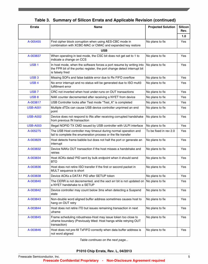
Table 3. Summary of Silicon Errata and Applicable Revision (continued)
Errata Name Projected Solution SiliconRev.
1.0
A-005455 First cipher block corruption when using AES-CBC mode incombination with XCBC-MAC or CMAC and expanded key restore
No plans to fix Yes
USB
A-003837 When operating in test mode, the CSC bit does not get set to 1 toindicate a change on CCS
No plans to fix Yes
USB 1 In host mode, when the software forces a port resume by writing intothe FPR bit of the portsc register, the port change detect interrupt bitis falsely fired
No plans to fix Yes
USB 3 Missing SOFs and false babble error due to Rx FIFO overflow No plans to fix Yes
USB 4 No error interrupt and no status will be generated due to ISO mult3fulfillment error
No plans to fix Yes
USB 7 CRC not inverted when host under-runs on OUT transactions No plans to fix Yes
USB 8 NAK counter decremented after receiving a NYET from device No plans to fix Yes
A-003817 USB Controller locks after Test mode "Test_K" is completed No plans to fix Yes
USB-A001 Multiple dTDs can cause USB device controller unprimed an endpoint
No plans to fix Yes
USB-A002 Device does not respond to INs after receiving corrupted handshakefrom previous IN transaction
No plans to fix Yes
USB-A003 Illegal NOPID TX CMD issued by USB controller with ULPI interface No plans to fix Yes
A-005275 The USB Host controller may timeout during normal operation andfail to complete the enumeration process or the file transfer
To be fixed in rev 2.0 Yes
A-003829 Host detects frame babble but does not halt the port or generate aninterrupt
No plans to fix Yes
A-003832 Device NAKs OUT transaction if the host misses a handshake andretries
No plans to fix Yes
A-003834 Host ACKs data2 PID sent by bulk endpoint when it should sendBTO
No plans to fix Yes
A-003836 Host does not retire ISO transfer if the first or second packet inMULT sequence is short
No plans to fix Yes
A-003838 Device ACKs a DATA1 PID after SETUP token No plans to fix Yes
A-003840 The CERR is not decremented, and the xact err bit is not updated ona NYET handshake to a SETUP
No plans to fix Yes
A-003842 Device controller may count below 3ms when detecting a Suspendstate
No plans to fix Yes
A-003843 Non-double word aligned buffer address sometimes causes host tohang on OUT retry
No plans to fix Yes
A-003844 Host does not retire iTD but issues remaining transaction in nextuframe
No plans to fix Yes
A-003845 Frame scheduling robustness-Host may issue token too close touframe boundary (Previously titled: Host hangs while retrying OUTtransaction)
No plans to fix Yes
A-003846 Host does not pre-fill TxFIFO correctly when data buffer address isnot word aligned
No plans to fix Yes
Table continues on the next page...
P1010 Chip Errata, Rev. L, 04/2013
Freescale Semiconductor, Inc. 5Freescale Confidential Proprietary - Non-Disclosure Agreement required
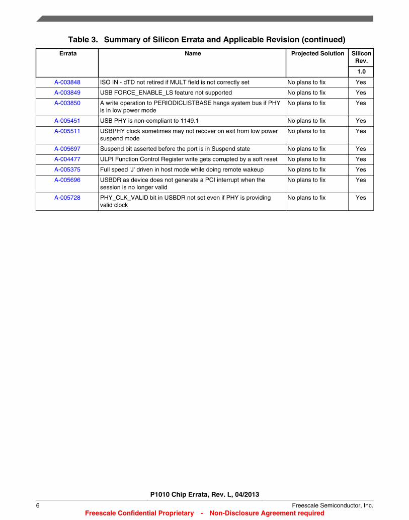
Table 3. Summary of Silicon Errata and Applicable Revision (continued)
Errata Name Projected Solution SiliconRev.
1.0
A-003848 ISO IN - dTD not retired if MULT field is not correctly set No plans to fix Yes
A-003849 USB FORCE_ENABLE_LS feature not supported No plans to fix Yes
A-003850 A write operation to PERIODICLISTBASE hangs system bus if PHYis in low power mode
No plans to fix Yes
A-005451 USB PHY is non-compliant to 1149.1 No plans to fix Yes
A-005511 USBPHY clock sometimes may not recover on exit from low powersuspend mode
No plans to fix Yes
A-005697 Suspend bit asserted before the port is in Suspend state No plans to fix Yes
A-004477 ULPI Function Control Register write gets corrupted by a soft reset No plans to fix Yes
A-005375 Full speed 'J' driven in host mode while doing remote wakeup No plans to fix Yes
A-005696 USBDR as device does not generate a PCI interrupt when thesession is no longer valid
No plans to fix Yes
A-005728 PHY_CLK_VALID bit in USBDR not set even if PHY is providingvalid clock
No plans to fix Yes
P1010 Chip Errata, Rev. L, 04/2013
6 Freescale Semiconductor, Inc.Freescale Confidential Proprietary - Non-Disclosure Agreement required
A-005125: In a very rare condition, a system hang is possible when the e500 coreinitiates a guarded load to PCI/PCIe/SRIO performs a coherent write tomemory.
Affects: CPUDescription: When the e500 core initiates a guarded load to the PCI/PCIe/SRIO performs a write to
cacheable, coherent memory, and that write is behind (or is one of) multiple full cache linewrites from an IO device that hit modified in the e500's L1 data cache, it is possible for theCCB bus arbiter to enter into an invalid state and hang the system. A very specific sequence ofstreamed IO snoops and retries from a congested memory system must occur just before thePCI/PCIe/SRIO write reaches the core for the hang to occur.
Impact: When the erratum is encountered, no further forward progress is made to and from the e500coherency module (ECM), and the system may hang.
Workaround: Set SPR976[40:41] to b’10. Setting these bits avoids the hang condition by forcing the core toprocess all snoops of IO device full cache line writes to DDR differently. This setting does notimpact performance.
Fix plan: No plans to fix
P1010 Chip Errata, Rev. L, 04/2013
Freescale Semiconductor, Inc. 7Freescale Confidential Proprietary - Non-Disclosure Agreement required
CPU 1: "mbar MO = 1" instruction fails to order caching-inhibited guarded loads andstores
Description: This errata describes a failure of the e500 mbar instruction when the MO field is one. Inparticular, the "mbar MO = 1" instruction fails to act as a barrier which cannot be bypassed bycaching-inhibited loads.
Assume the following instruction sequence:• stw caching-inhibited, guarded address A• mbar MO = 1• lwz caching-inhibited, guarded address B
The “mbar MO = 1” instruction is intended to be a barrier which prevents the lwz fromexecuting before the stw has been performed. However, the e500 does not behave asintended, and allows the lwz to be executed before the stw has been performed.
Impact: This errata is most likely to affect device drivers that depend on “mbar MO = 1” to ensure thatthe effects of caching-inhibited stores are seen by a device before a subsequent caching-inhibited guarded load is executed.
The “mbar MO = 1” instruction is intended to order:
• Cacheable stores• Cache-inhibited loads• Cache-inhibited stores
The only case where the instruction may not behave correctly is where cache-inhibited loadsmay erroneously bypass cache-inhibited stores.
Workaround: Use "mbar MO = 0" to ensure that caching-inhibited guarded loads do not bypass the memorybarrier.
Fix plan: No plans to fix
P1010 Chip Errata, Rev. L, 04/2013
8 Freescale Semiconductor, Inc.Freescale Confidential Proprietary - Non-Disclosure Agreement required
CPU 2: Single-precision floating-point zero value may have the wrong sign
Description: When performing single-precision floating-point operations that produce a result of zero, thesign of the zero value may be incorrect.
Impact: Single-precision floating-point operations that result in zero may not be compatible with IEEEStd 754™.
Workaround: Use double-precision floating-point
Fix plan: No plans to fix
P1010 Chip Errata, Rev. L, 04/2013
Freescale Semiconductor, Inc. 9Freescale Confidential Proprietary - Non-Disclosure Agreement required
A-001428: Enabling IEEE 754 exceptions can cause errors
Affects: CPUDescription: This issue can occur if a single-precision floating-point, double-precision floating-point, or
vector floating-point instruction on a mispredicted branch path signals one of the floating-pointdata interrupts enabled by the SPEFSCR (FINVE, FDBZE, FUNFE or FOVFE bits). Thisinterrupt must be recorded in a one-cycle window when the misprediction is resolved.
If this extremely rare event should occur, the result could be that the SPE Data Exception fromthe mispredicted path may be reported erroneously if a single-precision floating-point, double-precision floating-point, or vector floating-point instruction is the second instruction on thecorrect branch path.
It is only possible for this erratum to occur if any of the SPEFSCR exception enable bits(FINVE, FDBZE, FUNFE or FOVFE) are set to one.
Impact: A correctly executing floating point instruction that is the second instruction on the correct pathmay take an unexpected data exception. This is caused by an unrelated floating pointinstruction that has been cancelled on the mispredicted path.
Workaround: Use one of the following options:• Ensure that the floating-point data exceptions are disabled by clearing the SPEFSCR
exception enable bits (FINVE, FDBZE, FUNFE or FOVFE).• Have the exception handler make the hardware re-execute the instruction, if a floating
point instruction causes an unexpected data exception. If the exception was a result ofthis erratum, there will be no exception on re-execution. Freescale will make thismodification to the exception handler we provide to the open source community.
Fix plan: No plans to fix
P1010 Chip Errata, Rev. L, 04/2013
10 Freescale Semiconductor, Inc.Freescale Confidential Proprietary - Non-Disclosure Agreement required
A-003477: Phantom branches in the BTB may not be correctly invalidated
Affects: CPUDescription: The branch target buffer (BTB) holds effective addresses associated with a branch instruction.
A process context switch might bring in another task whose MMU translations are such that ituses the same effective address for another nonbranch instruction for which the BTB has anentry for a previously encountered branch. This causes the fetch unit to redirect instructionfetch to the BTB’s target address. When this occurs it is called a phantom branch. Later, duringexecution of the instruction, the hardware realizes the error and is supposed to evict the BTBentry.
However, with this erratum, a BTB entry of a phantom branch may not be invalidated when thephantom branch is decoded from instruction buffer 0, and
1. the BTB hit a phantom branch and the branch address does not equal the fetch groupaddress, that is, the branch is not the first instruction in the fetch group, OR,
2. the BTB hit a phantom branch and the branch address equals the fetch group address.
In case 1, where the fetch group address and branch address are not equal, the BTB will notbe invalidated. In case 2, after two attempts to issue the phantom branch, the BTB entry will beproperly invalidated. In both cases, it is possible that a valid entry will be invalidated instead.
Impact: Performance may be impacted due to possible additional phantom branches. This errata couldoccur when switching across processes that share the same effective address space.
Workaround: Select one of the following options, depending on which results in the best performance:• Continue to use the BTB as it currently operates.• Invalidate the BTB (BUCSR [BBFI] =1) at the appropriate points to ensure a phantom
branch never occurs. (Possible scenarios that can cause phantom branches include, butare not limited to, the following: switching contexts where an exception handler addressspace overlaps with user code space, while running self-modifying code, 64-bit programsexecuting across 4G segments, during any process switch, and so on.)
• Disable the BTB (BUCSR[BPEN] = 0) temporarily without invalidating the BTB whenswitching to other contexts that may cause phantom branches. Re-enable the BTB whenswitching back to the main context. This allows the BTB contents to remain intact for themain context such that when returning back to the main context, the BTB is valid.
• Disable BTB (BUCSR[BPEN] = 0) completely for all contexts.
Each workaround impacts performance depending on the application.
Fix plan: No plans to fix
P1010 Chip Errata, Rev. L, 04/2013
Freescale Semiconductor, Inc. 11Freescale Confidential Proprietary - Non-Disclosure Agreement required

A-006184: Simultaneous Instruction L1 MMU (I-L1VSP) miss (due to eviction) andinterrupt servicing can cause a core hang
Affects: CPUDescription: A system hang is possible when an exception occurs at the same time as several other
internal core conditions occur. For the hang to happen, the L2 MMU TLB1 entry which mapsthe translation for the first instruction in the exception handler must not be in the I-L1VSP.
Impact: No further forward progress will be made until a higher priority exception is received for whichinterrupts are enabled.
Workaround: Option 1 (All of the following steps must be performed):1. Do not use more than 4 TLB1 entries, and ensure all interrupt handlers are mapped to
one of the 4 TLB1 entries with a TID=0 and IPROT=1.2. Prevent explicit invalidation of the TLB1 entry that contains the interrupt handler page by
not overwriting or invalidating it (never clear the valid bit).3. Prevent non-explicit invalidations of the TLB1 entry that contains the interrupt handler
page by nevera. Setting MMUCSR0[L2TLB1_FI]b. Executing a tlbivax with RA[60:61] set to 0b11 (invalidate all).
This should not be executed from any core in the integrated device as tlbivax isbroadcast to all cores.
Software may perform non-explicit invalidations if:• The instructions for invalidation are mapped by the same TLB1 entry which maps the
interrupt handlers. This will normally be the case if the operating system maps all itsstatic executable code with a single TLB1 entry; AND
• All interrupts should be blocked while performing the actions (set MSR[EE], MSR[CE],MSR[ME] & MSR[DE] = 0))
Option 2 (All of the following steps must be performed):1. In order to restart a core that has hung due to this erratum, set the watchdog timer to take
an interrupt at some period greater than the decrementer interrupt interval, but smallerthan an unacceptable hang time.
2. Have software reset the watchdog timer trigger during the decrementer interrupt,ensuring the core only takes the watchdog interrupt if it is hung.
Notes:• This will still allow for hangs, but will put a limit on the degradation in performance.• If the software already performs critical interrupts, the core may still hang. If the customer
wants to set the “watchdog timer reset” field (TCR[WRC], (actual value will be SOCdependent), then a core reboot will exit the hang condition.
Fix plan: To be fixed in rev 2.0
P1010 Chip Errata, Rev. L, 04/2013
12 Freescale Semiconductor, Inc.Freescale Confidential Proprietary - Non-Disclosure Agreement required
DDR 8: Memory controller perfmon counter for read beats is inaccurate
Description: There is a memory controller performance monitor event counter register that counts the totalnumber of read beats on the DRAM interface. This event counter register may not accuratelyrepresent the total number of read beats transferred on the DRAM interface.
If a 32-bit DRAM interface is used, the count will be half as much as it should. If a 16-bit DRAMinterface is used, the count will be 1/4 as much as it should.
Impact: The results of this perfmon event counter will be inaccurate.
Workaround: Multiply the final count by 2 if a 32-bit DRAM data bus is used. Multiply the final count by 4 if a16-bit DRAM data bus is used.
Fix plan: No plans to fix
P1010 Chip Errata, Rev. L, 04/2013
Freescale Semiconductor, Inc. 13Freescale Confidential Proprietary - Non-Disclosure Agreement required
A-004508: DDR controller may not function across the full industrial temperaturerange
Affects: DDRDescription: When the DDR controller is initialized below a junction temperature of 0°C and then operated
above a junction temperature of 65°C, the DDR controller may cause receive data errors,resulting in single-bit ECC errors, multi-bit ECC errors and/or corrupted data.
Impact: Data corruption may be observed during reads from DRAM.
Workaround: When the DDR controller is initialized below a junction temperature of 0°C and then operatedabove a junction temperature of 65°C without a reset, then software should set bit 22 at theCCSR register offset 0x0_2F08 before the DDR controller is enabled. This ensures the DDRcontroller operates across the full, supported industrial temperature range.
Fix plan: No plans to fix
P1010 Chip Errata, Rev. L, 04/2013
14 Freescale Semiconductor, Inc.Freescale Confidential Proprietary - Non-Disclosure Agreement required
A-004737: BREAK detection triggered multiple times for a single break assertion
Affects: DUARTDescription: Previously DUART 1
A UART break signal is defined as a logic zero being present on the UART data pin for a timelonger than (START bit + Data bits + Parity bit + Stop bits). The break signal persists until thedata signal rises to a logic one.
A received break is detected by reading the ULSR and checking for BI = 1. This read to ULSRclears the BI bit. After the break is detected, the normal handling of the break condition is toread the URBR to clear the ULSR[DR] bit. The expected behavior is that the ULSR[BI] andULSR[DR] bits do not get set again for the duration of the break signal assertion. However, theULSR[BI] and ULSR[DR] bits continue to get set each character period after they are cleared.This continues for the entire duration of the break signal.
At the end of the break signal, a random character may be falsely detected and received in theURBR, with the ULSR[DR] being set.
Impact: The ULSR[BI] and ULSR[DR] bits get set multiple times, approximately once every characterperiod, for a single break signal. A random character may be mistakenly received at the end ofthe break.
Workaround: The break is first detected when ULSR is read and ULSR[BI]=1. To prevent the problem fromoccurring, perform the following sequence when a break is detected:
1. Read URBR, which returns a value of zero, and clears the ULSR[DR] bit2. Delay at least 1 character period3. Read URBR again, which return a value of zero, and clears the ULSR[DR] bit
ULSR[BI] remains asserted for the duration of the break. The UART block does not trigger anyadditional interrupts for the duration of the break.
This workaround requires that the break signal be at least 2 character-lengths in duration.
This workaround applies to both polling and interrupt-driven implementations.
Fix plan: No plans to fix
P1010 Chip Errata, Rev. L, 04/2013
Freescale Semiconductor, Inc. 15Freescale Confidential Proprietary - Non-Disclosure Agreement required
A-004373: Host may not detect SD card insertion/removal using DAT3 signal
Affects: eSDHCDescription: There is an on-chip pull-down resistor on the DAT3 signal that prevents the eSDHC host from
correctly detecting card insertion or removal. The card has an internal pull-up of value 10-90KOhms on the card detect pin, as defined in the SD specification. If the internal pull-up resistorvalue of the SD card is greater than 60KΩ, the card detection mechanism might not workproperly.
Impact: Customer cannot use the sense DAT3 signal method for SD card detection.
Workaround: Do not use the DAT3 sensing method for card detection. Instead, use any of the followingmethods, as described in the application note for card detection provided by the SDOrganization.
1. Using the CD pin on socket. This is a hardware solution. Note that this can be used onlyif the card socket provides the CD pin. Due to the on-chip pull-down on the I/O pin, a 10–50K Ohms pull-up resistor is needed for an active low polarity.
2. Polling SD memory card. This is a software solution. Check the response of theSEND_OP_CONDITION command to determine card insertion, and check theSEND_STATUS command to determine card removal.
Fix plan: No plans to fix
P1010 Chip Errata, Rev. L, 04/2013
16 Freescale Semiconductor, Inc.Freescale Confidential Proprietary - Non-Disclosure Agreement required
A-005055: Glitch is generated on the card clock with software reset or a clock dividerchange
Affects: eSDHCDescription: A glitch may occur on the SDHC card clock when the software sets the SYSCTL[RSTA] bit
(that is, performs a software reset). It can also be generated by setting the clock divider value.The glitch produced can cause the external card to switch to an unknown state. Theoccurrence is not deterministic and it happens rarely. The next command causes a timeouterror(IRQSTAT[CTOE]) after this issue occurs.
Impact: Changing the frequency or performing a software reset for all may not work reliably.
Workaround: When the timeout error occurs for the command right after the SYSCTL[RSTA] is set or theclock divider value is changed, send CMD0 to bring the card to idle state, and perform re-initialization again. If the error occurs again, repeat this step until the initialization processcompletes.
Fix plan: No plans to fix
P1010 Chip Errata, Rev. L, 04/2013
Freescale Semiconductor, Inc. 17Freescale Confidential Proprietary - Non-Disclosure Agreement required
A-004388: eSDHC DMA might not stop if error occurs on system transaction
Affects: eSDHCDescription: eSDHC DMA(SDMA/ADMA) might not stop if an error occurs in the last system transaction. It
may continue initiating additional transactions until software reset for data/all is issued duringerror recovery.
There is no data corruption to the SD data. The IRQSTAT[DMAE] is set when the erratumoccurs.
This issue only occurs under the following conditions:
1. SDMA - For SD Write , the error occurs in the last system transaction. No issue for SDread
2. ADMAa. Block count is enabled: For SD write, the error occurs in the last system transaction.
There is no issue for SD read when block count is enabled.b. Block count is disabled: Block count is designated by the ADMA descriptor table,
and the error occurs in the last system transaction when ADMA is executing lastdescriptor line of table.
Impact: eSDHC may initiate additional system transactions. There is no data integrity issue for case 1and 2a. For case 2b, system data might be corrupted.
Workaround: Set eSDHC_SYSCTL[RSTD] when IRQSTAT[DMAE] is set. For cases 2a and 2b, add anextra descriptor line with zero data next to the last descriptor line.
Fix plan: No plans to fix
P1010 Chip Errata, Rev. L, 04/2013
18 Freescale Semiconductor, Inc.Freescale Confidential Proprietary - Non-Disclosure Agreement required
A-006414: Reading the DATPORT register while a DMA mode transaction is inprogress may hang the system
Affects: eSDHCDescription: Reading the DATPORT register while a DMA mode transaction is in progress may result in a
system hang as defined in the different senarios below:• If a SD_READ transaction ends with a data timeout error and the software issues another
SD_READ command instead of performing error recovery. In this case, the reading of theDATPORT register can hang the system.
• If a SD_READ is issued in the CPU polling mode and the software doesn't read thecomplete data from DATPORT register. The software issues an abort command toterminate the transaction without performing the recommended (in the SD SpecificationsPart A2, SD Host Controller Standard Specification) data reset (RSTD) to reset theeSDHC data path. In this case, if the software issues the next SD_READ command inDMA mode and then tries to read the DATPORT register, it can hang the system.
Impact: System operations might hang if the DATPORT register is read while a DMA mode transactionis in progress.
Workaround: Software should follow the SD host specification sequences and do not read DATPORTregister in case DMA mode transaction is running.
Fix plan: No plans to fix
P1010 Chip Errata, Rev. L, 04/2013
Freescale Semiconductor, Inc. 19Freescale Confidential Proprietary - Non-Disclosure Agreement required
eTSEC 4: VLAN Insertion corrupts frame if user-defined Tx preamble enabled
Description: When TCTRL[VLINS] = 1, the VLAN is supposed to be inserted into the Tx frame 12 bytesafter start of the Destination Address (after DA and SA). If user-defined Tx preamble isenabled (MACCFG2[PreAmTxEn] = 1), the VLAN ID is inserted 12 bytes after the start of thepreamble (4 bytes after start of DA), thus overwriting part of DA and SA.
Impact: If VLAN insertion is enabled with user-defined Tx preamble, the VLAN ID corrupts the Tx framedestination and source addresses.
Workaround: Use one of the following workarounds:
• Disable user-defined Tx preamble by setting MACCFG2[PreAmTxEn] = 0.
• Disable VLAN insertion by setting TCTRL[VLINS] = 0.
Fix plan: No plans to fix
P1010 Chip Errata, Rev. L, 04/2013
20 Freescale Semiconductor, Inc.Freescale Confidential Proprietary - Non-Disclosure Agreement required
eTSEC 8: Half-duplex collision on FCS of Short Frame may cause Tx lockup
Description: In half-duplex mode, if a collision occurs in the FCS bytes of a short (fewer than 64 bytes)frame, then the Ethernet MAC may lock up and stop transmitting data or control frames. Only areset of the controller can restore proper operation once it is locked up.
Impact: A collision on hardware-generated FCS bytes of a short frame in half-duplex mode may causea Tx lockup.
Workaround: Option 1:
Set MACCFG2[PAD/CRC] = 1, which pads all short Tx frames to 64 bytes.
Option 2:
Use software-generated CRC (MACCFG2[PAD/CRC] = 0, MACCFG2[CRC EN] = 0 andTxBD[TC] = 0)
Fix plan: No plans to fix
P1010 Chip Errata, Rev. L, 04/2013
Freescale Semiconductor, Inc. 21Freescale Confidential Proprietary - Non-Disclosure Agreement required
eTSEC 9: Magic Packet Sequence Embedded in Partial Sequence Not Recognized
Description: The Ethernet MAC should recognize Magic Packet sequences as follows:
Any Ethernet frame containing a valid Ethernet header (Destination and Source Addresses)and valid FCS (CRC-32), and whose payload includes the specific Magic Packet bytesequence at any offset from the start of data payload. The specific byte sequence comprisesan unbroken stream of 102 bytes, the first 6 bytes of which are 0xFFs, followed by 16 copies ofthe MAC's unique IEEE station address in the normal byte order for Ethernet addresses.
If a complete Magic Packet sequence (including 6 bytes of 0xFF) immediately follows a partialMagic Packet sequence, however, the complete sequence will not be recognized and the MACwill not exit Magic Packet mode.
The following are example partial sequences followed by the start of a complete sequence forstation address 01_02_03_04_05_06:
• FF_FF_FF_FF_FF_FF_FF_01_02_03_04_05_06_01...
Seventh byte of 0xFF does not match next expected byte of Magic Packet Sequence(01). Pattern search restarts looking for 6 bytes of FF at byte 01.
• FF_FF_FF_FF_FF_FF_01_FF_FF_FF_FF_FF_FF_01_02_03_04_05_06_01...
First FF byte following 01 does not match Magic Packet sequence.
Pattern search restarts looking for 6 bytes of FF at second byte of FF following 01.
Impact: The Ethernet controller will not exit Magic Packet mode if the Magic Packet sequence is placedimmediately after other frame data which partially matches the Magic Packet Sequence.
Workaround: Place 1 byte of data that is not 0xFF and does not match any bytes of DA before the start ofthe Magic Packet sequence in the frame.
Because the Magic Packet sequence pattern search starts at the 3rd byte after DA, the MagicPacket Sequence can be placed at the start of the data payload as long as the second byte ofthe length/type field follows the above rule.
Fix plan: No plans to fix
P1010 Chip Errata, Rev. L, 04/2013
22 Freescale Semiconductor, Inc.Freescale Confidential Proprietary - Non-Disclosure Agreement required

eTSEC 11: VLAN extraction with shim header not supported
Description: Shim header shifts the eTSEC header, including the VLAN ID, by 2 to 254 bytes. The VLANextraction feature of the controller does not take that shift into account, and examines bytesfrom the wrong offset of the header. In most cases, the data at the unshifted offset does notmatch the VLAN ID, so no extraction occurs and nothing is forwarded to the filer.
If the data at the unshifted offset happens to match the VLAN ID by coincident (0x8100 or thevalue in DFVLAN), then those bytes are incorrectly extracted from the frame and forwarded tothe filer and the actual VLAN ID, if any, will be left in the frame.
Impact: VLAN extraction cannot be used if shim headers are enabled.
Workaround: If shim headers are enabled (RCTRL[L2OFF] ≠ 0), disable VLAN extraction (by settingRCTRL[VLEX] = 0).
Fix plan: No plans to fix
P1010 Chip Errata, Rev. L, 04/2013
Freescale Semiconductor, Inc. 23Freescale Confidential Proprietary - Non-Disclosure Agreement required
eTSEC-A002: Incomplete GRS or invalid parser state after receiving a 1- or 2-byteframe
Description: Ethernet standards define the minimum frame size as 64 bytes. The eTSEC controller alsosupports receiving short frames less than 64B, and can accept frames more than 16B and lessthan 64B if RCTRL[RSF] = 1. Frames shorter than 17 bytes are supposed to be silentlydropped with no side-effects. There are, however, two scenarios in which receiving frames <=2B cause erroneous behavior in the controller.
In the first scenario, if the last frame (such as an illegal runt packet or a packet with RX_ERasserted) received prior to asserting graceful receive stop (DMACTRL[GRS]=1) is <= 2 bytes,then the controller will fail to signal graceful receive stop complete (IEVENT[GRSC]) eventhough the GRS has successfully executed and the receive logic is completely idle. Anysubsequent receive frame which is larger than 2 bytes will reset the state so the graceful stopcan complete. An Rx reset will also reset the state.
In the second scenario, the parser and filer are enabled (RCTRL[PRSDEP] = 01,10,11). If a 1or 1.5B frame is received, the controller will carry over some state from that frame to the next,causing the next frame to be parsed incorrectly. This in turn may cause incorrect parser resultsin RxFCB and incorrect filing (accept versus reject, or accept to wrong queue) for that followingframe. The parser state recovers itself after receiving any frame >= 2B in length.
Impact: If software initiates a graceful receive stop after a 1- or 2-byte frame is received, the stop maynot complete until another frame has been received.
A frame following a 1 or 1.5B frame may be parsed and filed incorrectly.
Workaround: For GRS scenario:
After asserting graceful receive stop (DMACTRL[GRS] = 1), initiate a timeout counter. The waittime is system and memory dependent, but a reasonable worst-case time is the receive timefor a 9.6 Kbyte frame at 10/100/1000 Mbps. If IEVENT[GRSC] is still not set after the timeout,read the eTSEC register at offset 0xD1C. If bits 7-14 are the same as bits 23-30, the eTSECRx is assumed to be idle and the Rx can be safely reset. If the register fields are not equal,wait for another timeout period and check again.
MAX Rx reset procedure:
1) Clear MACCFG[RX_EN].
2) Wait three Rx clocks.
3) Set MACCFG2[RX_EN].
Fix plan: No plans to fix
P1010 Chip Errata, Rev. L, 04/2013
24 Freescale Semiconductor, Inc.Freescale Confidential Proprietary - Non-Disclosure Agreement required
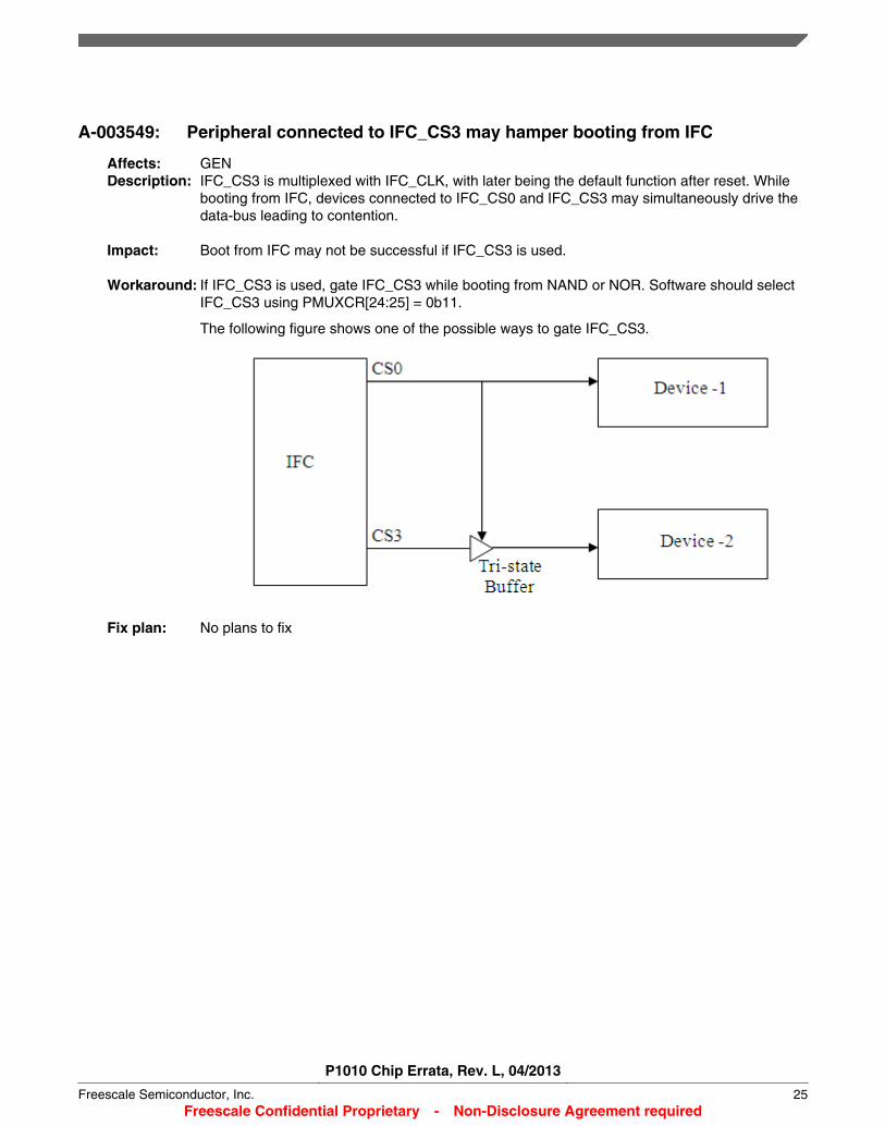
A-003549: Peripheral connected to IFC_CS3 may hamper booting from IFC
Affects: GENDescription: IFC_CS3 is multiplexed with IFC_CLK, with later being the default function after reset. While
booting from IFC, devices connected to IFC_CS0 and IFC_CS3 may simultaneously drive thedata-bus leading to contention.
Impact: Boot from IFC may not be successful if IFC_CS3 is used.
Workaround: If IFC_CS3 is used, gate IFC_CS3 while booting from NAND or NOR. Software should selectIFC_CS3 using PMUXCR[24:25] = 0b11.
The following figure shows one of the possible ways to gate IFC_CS3.
Fix plan: No plans to fix
P1010 Chip Errata, Rev. L, 04/2013
Freescale Semiconductor, Inc. 25Freescale Confidential Proprietary - Non-Disclosure Agreement required
A-003571: Multiple read/write transactions initiated by Security engine may cause thedevice hang
Affects: GENDescription: Multiple read/write transactions initiated by Security engine may cause system to hang.
System can be recovered only by POR cycle.
Impact: When Security engine is used the device may hang.
Workaround: Set MCFGR[AXIPIPE] to 0 to avoid hang.
Fix plan: To be fixed in rev 2.0
P1010 Chip Errata, Rev. L, 04/2013
26 Freescale Semiconductor, Inc.Freescale Confidential Proprietary - Non-Disclosure Agreement required

A-004447: Nine SCL pulses cannot be generated when SDA is held low with thesequence provided in documentation
Affects: I2CDescription: The applicable device reference manual provides a scheme that allows the I2C master
controller to generate nine SCL pulses, which enable an I2C slave device that held SDA low torelease SDA. However, due to this erratum, this scheme no longer works. In addition, whenI2C is used as a source of the PBL, the state machine is not able to recover.
Impact: In normal I2C mode, the scheme provided in the applicable device reference manual does notgenerate nine SCL pulses in order to release the SDA.
When PBL is used with I2C as the source, the PBL fails when the SDA is held low. In thiscase, a full system reset is needed.
Workaround: For normal I2C mode, the following sequence should be used to first determine if SDA is lowand then to generate the nine SCL pulses when SDA is low.
1. Set up the frequency divider and sampling rate.2. I2CCR -> 0xa03. Poll for I2CSR[MBB] to get set.4. If I2CSR[MAL] is set (an indication that SDA is stuck low), then go to step 5. If MAL is not
set, then go to step 12.5. I2CCR -> 0x006. I2CCR -> 0x227. I2CCR -> 0xa28. Issue read to I2CDR9. Poll for I2CSR[MIF] to be set.
10. I2CCR -> 0x8211. Workaround complete. Skip the next steps.12. Issue read to I2CDR.13. Poll for I2CSR[MIF] to be set.14. I2CCR -> 0x80
Fix plan: No plans to fix
P1010 Chip Errata, Rev. L, 04/2013
Freescale Semiconductor, Inc. 27Freescale Confidential Proprietary - Non-Disclosure Agreement required
A-006037: I2C could hang if disabled after enabling in multi-master system
Affects: I2CDescription: For a multi-master system, when the software tries to enable I2C via I2CCR[MEN], if I2C bus
is busy due to communication between other devices, I2C controller will not execute theregister write to I2CCR. Instead the transaction will be queued. I2C controller executes thewrite to I2CCR only after it sees SCL idle for 64K cycle of internal I2C controller clocks. Ifduring this waiting period, which could be very long (e.g. reading EEPROM array), I2Ccontroller is disabled(I2CCR[MEN] set to 0], then the controller could end in bad state, andhang the future access to I2C register.
Impact: I2C controller could hang if it is disabled after enabling in a multi-master system.
Workaround: The preferred solution is to enable the I2C controller before any I2C communication starts.Otherwise, during the very first I2C transaction and before the software proceeds, pollI2CSR[MIF] until the transaction finishes.
Fix plan: No plans to fix
P1010 Chip Errata, Rev. L, 04/2013
28 Freescale Semiconductor, Inc.Freescale Confidential Proprietary - Non-Disclosure Agreement required

A-002769: NOR-FCM does not support access to unaligned addresses for 16-bit portsize
Description: When NOR, with 16-bit data bus width, is accessed with an unaligned address, the NOR-FCMreturns incorrect data. For example, for a byte access to an unaligned address (say 0x01), theNOR-FCM returns data from the lower aligned address (i.e. 0x00).
Impact: When using 16-bit port size, accesses not aligned to 16 bit address boundary result inincorrect data.
Workaround: Option 1: Ensure that accesses targeted at NOR-FCM are port size aligned.
Option 2: Use x8 port size only.
Option 3: Use GPCM instead of NOR-FCM. Note that booting from GPCM is not supported. Toaccess NOR flash, which has zero output hold, using IFC’s GPCM, the following constraintswould apply:
• De-assertion of OE should be aligned with IFC_CLK. This can be achieved by ensuringthat the following condition is met:
FTIM0_CSn[TEADC] + FTIM0_CSn[TEAHC] + FTIM0_CSn[TACSE] +FTIM1_CSn[TACO] + FTIM1_CSn[TRAD] + (CCR[CLK_DIV] +1)/2 = Integer multiple of(CCR[CLK_DIV] + 1)
TRAD can be tweaked to meet this equation. For default values incrementing TRAD byone would satisfy the condition.
• Board routing delay on CS_B and OE_B signals should be greater than or equal to thedelay on data lines. However these delays should not be greater than 500ps.
Fix plan: No plans to fix
P1010 Chip Errata, Rev. L, 04/2013
Freescale Semiconductor, Inc. 29Freescale Confidential Proprietary - Non-Disclosure Agreement required
A-002770: False ECC error generation in NAND-FCM.
Description: ECCEREN may reflect/flag the false error indication.
If ECC error logging is enabled (ECCEREN=1), NAND-FCM sets the ECCER (UncorrectableECC indication) bit when the following three conditions are met:
1. OPC (operation complete indicator) bit toggles from zero to one.2. ECCSTAT0-3 (ECC error status registers) has logged uncorrectable errors for any
sector.3. ECC_DEC_EN (ECC decoder enable) is set.
This leads to a situation when NAND-FCM sets ECCER even if the uncorrectable error loggedin ECCSTATn register does not correspond to the recently read page.
NAND-FCM also sets ECCER when program/erase operations are performed and the threeconditions mentioned above are met.
Impact: NAND_EVTER_STAT[ECCER] may reflect false errors. These errors also trigger errorinterrupts if enabled.
Workaround: ECCSTAT0-3 reflects correct status of ECC errors. So after getting uncorrectable ECC errorinterrupt, software should check fields of ECCSTAT0-3, corresponding to recently read page toget the correct ECC error indication.
ECC decoder should also be disabled (ECC_DEC_EN=0) before initiating any operationexcept read.
Fix plan: No plans to fix
P1010 Chip Errata, Rev. L, 04/2013
30 Freescale Semiconductor, Inc.Freescale Confidential Proprietary - Non-Disclosure Agreement required
A-003399: Address masking doesn’t work properly
Description: When sum of the base address, defined by BA, and memory bank size, defined by AM,exceeds 4GB (0xffff_ffff) then AMASKn[AM] doesn’t mask CSPRn[BA] bits.
For example:
BA = 0xfff0 (base address = 0xfff0_0000) and
AM=0xff00 (bank size = 16MB = 0x00ff_ffff)
Sum = 0xfff0_0000 + 0x00ff_ffff = to 0x1_00EF_FFFF
As the sum is greater than 0xffff_ffff in the example above, the scenario will lead to an errorcondition.
Impact: Access to any address in the memory window defined by CSPRn[BA] and AMASKn[AM], willcause chip-select error (CSER = 1) if the condition described above is met.
Workaround: BA and AMASK should be programmed in such a way that sum of base address and bank sizefor a particular chip select doesn’t exceed 4G.
Fix plan: No plans to fix
P1010 Chip Errata, Rev. L, 04/2013
Freescale Semiconductor, Inc. 31Freescale Confidential Proprietary - Non-Disclosure Agreement required

A-004761: PCI Express link training may fail at cold boot - LTSSM stuck at 3Fh stateor looping
Affects: PCIeDescription: When coming out of hard reset of a cold boot, PCI Express controller’s link training may fail
and the internal logic may be stuck in an infinite training loop. This status can be determinedby reading the LTSSM state status register (offset 404h) in the PCI Express extendedconfiguration space.
When this failure occurs, the status code either remains at 3Fh or loops around between 32hand 38h upon read. If the link has been properly trained, the status code reads 16hconsistently.
Note that the LTSSM status code resides at the least significant byte (little endian) of the 32-bitLTSSM register. Software has to ensure that the checking of the LTSSM status code isperformed on the whole byte value.
Impact: When coming out of a hard reset of a cold boot, the PCI Express controller may fail to properlytrain with an active link partner. Please notice that warm boot (toggling HRESET_B after PORsequence is finished) is not affected by this error.
Workaround: Upon coming out of hard reset of a cold boot, wait for a period of 1 ms before beginningprobing the link training status by reading the LTSSM state status register (offset 404h) in thePCI Express extended configuration space. To confirm a successful link training condition, theLTSSM state status register should be read several times to confirm that the LTSSM statuscode stays at 16h consistently. If the LTSSM status code either remains at 3Fh or loopsaround between 32h and 38h upon read, it indicates that the internal logic is stuck in theinfinite training loop. The following procedures can be followed to bring the PCI Expresscontroller out of the infinite training loop.
Option 1
Perform a warm boot to the device.
Option 2
Perform a PCI Express controller soft reset with the following sequence in order.
1. Save the read return value for memory location “CCSRBAR + PCI Express controllerblock offset + F00h” to temporary locations, depending on the PCI Express controller inuse.
2. OR the above temporary values with 0800_0000h and write back the result to thememory location CCSRBAR + PCI Express contoller block offset + F00h.
3. Wait 1 ms.4. AND the temporary values obtained in Step 1 with F7FF_FFFFh and write back the result
to the memory location “CCSRBAR + PCI Express controller block offset + F00h”.5. Poll the LTSSM register until the LTSSM status code returns 16h consistently to indicate
that the link is up.
Option 3
Use a platform CCB frequency of 400 MHz if applicable. Note that a clock ratio adjustmentmight be necessary to ensure that the hardware specification requirement is not violated.
Fix plan: No plans to fix
P1010 Chip Errata, Rev. L, 04/2013
32 Freescale Semiconductor, Inc.Freescale Confidential Proprietary - Non-Disclosure Agreement required
A-004033: False Detected Parity Error (DPE) bit set in the Secondary Status registerwhen entering electrical idle in RC mode
Affects: PCIeDescription: When running at either 5.0 GT/s (Gen2) or 2.5 GT/s (Gen1) speed and any link width, during
the PCI Express link training, a false Detected Parity Error (DPE, bit 15) may be recorded inthe Secondary Status register of the PCI Express RC controller.
The PCI Express controller includes support for L0s and L1 low-power interconnect states, inwhich the link is taken to an electrical idle condition, and can be taken back to L0 state withouta full device reset. The transmitter's L0s ASPM (active state power management) is enabledthrough the PCI Express Link Control register. Other power states are controlled through thePCI Express Power Management Status and Control register.
The PCI Express controller and PHY should be able to negotiate entering electrical idle withouterrors, using the normal PCI Express recovery and retraining mechanism. However, instabilityon the receiver may lead to a false detected parity error (DPE, bit 15) recorded in theSecondary Status register of the PCI Express RC controller, after entering electrical idle.
Impact: Note that, this erratum only affects the PCI Express controller configured in RC mode.
The false DPE can cause an interrupt if enabled by clearing the M_DPE (Mask detected parityerror) bit in the PCI Express Secondary Status Interrupt Mask register (at configuration spaceoffset 5A0h).
Other than the false DPE bit being recorded, the link training can complete successfully andnormal traffic can be carried out after training.
Workaround: To eliminate the impact after the link training, once the training is completed (severalsuccessive read to LTSSM gets 16h return value consistently, which indicates the link is in L0or link up state), software needs to clear the Detected Parity Error (DPE) bit in the SecondaryStatus register of the PCI Express RC controller, before proceeding with normal PCI Expresstraffic.
To eliminate the impact to the controller when it's brought to the ASPM and other low powerinterconnect states, apply both workarounds below:
1. Disable ASPM with either one of the following options:a. The PCI Express ASPM policy is normally controlled globally by the operating
system. If it's feasible, turn off the ASPM support globally in the OS for the wholePCI Express fabric that the device belongs to.
b. If ASPM cannot be turned off globally, the ASPM support of the affected device'sPCI Express link can be disabled by setting the PCI Express link Control register[ASPM_CTL] = 00b for both the Freescale PCI Express RC controller and its linkpartner.
2. When programming the device to non-D0 state from D0 state (allowing the link totransition from L0 to L0s, L1 state), execute the following sequence:
a. Follow the PCI Express base specification guideline to ensure the PCI Expresstraffic is quiesced before preparing the system for non-D0 state.
b. Save the existing state of M_PDE bit in the PCI Express Secondary Status InterruptMask register (at RC controller's configuration space offset 5A0h) to a temporaryvariable.
c. Set the M_PDE bit to 1 in PCI Express Secondary Status Interrupt Mask register.d. Set PCI Express Power Management Status and Control register to the desired
state (D1, D2 or D3). Refer to the Reference Manual, Power Management section
P1010 Chip Errata, Rev. L, 04/2013
Freescale Semiconductor, Inc. 33Freescale Confidential Proprietary - Non-Disclosure Agreement required
in the PCI Express Interface Controller chapter for detailed steps to follow on how totransition from D0 to non-D0 state.
e. The PCI Express Controller is now in non-D0 state.f. When the system is transitioning back from non-D0 to D0 state, poll the LTSSM
register until it reaches L0 state stably (the return value of the LTSSM read shouldbe 16h consistently on several successive reads) upon exiting from electrical idle.Both the Negotiated Link Width and Negotiated Link Speed bits of the Link Statusregister (at configuration space offset 5Eh) should be polled as well, to ensure thePCI Express controller reaches the L0 state with the expected link width and speed.
g. Write 1 to clear the false DPE bit in Secondary Status register (at RC controller'sconfiguration space offset 1Eh).
h. Restore the original state of M_PDE bit in PCI Express Secondary Status InterruptMask register (at RC controller's configuration space offset 5A0h)
Fix plan: No plans to fix
P1010 Chip Errata, Rev. L, 04/2013
34 Freescale Semiconductor, Inc.Freescale Confidential Proprietary - Non-Disclosure Agreement required
A-004409: Selectable de-emphasis not supported with auto-detect polarity inversion
Affects: PCI ExpressDescription: PCI Express supports selectable de-emphasis (Link Control 2 Register [SDE]) and also
supports polarity inversion via auto-detection during training. If Link Control 2 Register [SDE] =1 and the controller detects polarity inversion during training, the LTSSM may get stuck in thePolling - Detect states.
Impact: The link may not complete training if selectable de-emphasis is enabled and the device isconnected to an inverted polarity PCI Express link.
Workaround: Leave the selectable de-emphasis (Link Control 2 Register [SDE]) at the default value of 0 toavoid the issue.
Fix plan: No plans to fix
P1010 Chip Errata, Rev. L, 04/2013
Freescale Semiconductor, Inc. 35Freescale Confidential Proprietary - Non-Disclosure Agreement required
A-005754: PCI Express controller fails to immediately return to L0 state upon exitingof L0s state in Gen1 mode
Affects: PCIeDescription: Per PCI Express base specification, the link should be able to return to the L0 state
immediately when exiting from the L0s state after sending out a predefined number of fasttraining sequence (FTS) ordered sets. However, in Gen1 mode (2.5G), the PCI Expresscontroller fails to immediately return to L0 state when exiting from the L0s state. Instead, aftersending out the default 64 FTS ordered sets, the link has to go through recovery state beforesuccessfully going back to the L0 state.
Impact: It takes a longer time for the PCI Express controller to get back to L0 state from L0s state.
Workaround: To avoid the impact, before enabling ASPM Control for both the PCI Express controller and itslink partner, perform the following sequence to clear the COMMA_NUM bit field (bits [29:31]) ofthe SerDes register PCVTRPEXnCR0 for each PCI Express controller in use, where the 'n'stands for the PCI Express controller n in use.
1. Save the read return value for the PCVTRPEXnCR0 register to temporary locations,depending on the PCI Express controller in use.
2. AND the temporary values obtained in Step 1 with FFFF_FFF8h and write back the resultto the same PCVTRPEXnCR0 register.
The SerDes register PCVTRPEXnCR0 for each PCI Express controller is located at thefollowing CCSR space address:
• PCI Express controller 1: CCSRBAR + E_3000h + 90h• PCI Express controller 2: CCSRBAR + E_3100h + 90h
Fix plan: No plans to fix
P1010 Chip Errata, Rev. L, 04/2013
36 Freescale Semiconductor, Inc.Freescale Confidential Proprietary - Non-Disclosure Agreement required
A-005636: Auto-activate feature enabled in DMA setup command causes timeout
Affects: SATADescription: When NCQ is enabled, the SATA controller does not support DMA setup FIS with auto-
activate enabled from the device. The SATA host may timeout without finishing the transaction.
Impact: This will have a minor performance impact as disabling the auto-activate feature requires thedevice to send a DMA setup as well as a DMA activate FIS to enable reception of the first dataFIS.
Workaround: Software can work around this with one of the following options:
• Disable the DMA setup auto-activate feature by a set features command.• Or, disable NCQ by setting the queue depth to one.
Fix plan: No plans to fix
P1010 Chip Errata, Rev. L, 04/2013
Freescale Semiconductor, Inc. 37Freescale Confidential Proprietary - Non-Disclosure Agreement required
A-005637: When a received data packet is smaller than the programmed length in theATAPI command, the SATA host controller raises a false fatal error
Affects: SATADescription: When an ATAPI device (for example, a CD or DVD-ROM drive) is connected to the SATA
interface, the following sequence may occur:
1. The SATA controller issues an ATAPI command (the ‘A’ bit in command Header DW3 isset) with a certain value in the ttl field (that is, the DW2 of the Command Header).
2. The ATAPI device responds with a data FIS.3. The length of data in the data FIS is smaller than the value programmed in the ttl field.4. The SATA controller raises the following errors:
• HSTATUS[DLM]• HSTATUS[FE]• HSTATUS[DE]• SERROR[E]• CE• DE
5. On receiving a fatal error (HSTATUS[FE]), the SATA driver issues a hardware reset tothe device.
The ttl field is based on maximum ALLOCATION LENGTH as per the SCSI commandReference Manual. The actual data transfer length may be less than the ALLOCATIONLENGTH and should not result in an error.
Impact: Frequent resets are observed on the bus.
Workaround: When a fatal error is received along with the Data Length Mismatch error in response to anATAPI command, perform the following:
1. Set HCONTROL[27].2. Clear HCONTROL[27].3. Clear the SERROR[E].4. Do not issue a hardware reset on the bus.
Fix plan: No plans to fix
P1010 Chip Errata, Rev. L, 04/2013
38 Freescale Semiconductor, Inc.Freescale Confidential Proprietary - Non-Disclosure Agreement required

A-005035: Possible data loss if PRD[DBA] or PRD[DWC] is not at least 16-bytealigned
Affects: SATADescription: SATA controller by design always tries to reach 64 byte alignment. If the PRD[DBA] or
PRD[DWC] is not 64 byte aligned, then in the beginning or the end of transaction, it has to use32-byte, 16-byte, 4-byte size transaction.
Impact: SATA controller may lose data when it tries to do 4-byte transaction.
Workaround: Software must make sure both PRD[DBA] and PRD[DWC] are at least 16-byte aligned so thatthe SATA controller would avoid 4-byte access.
Fix plan: No plans to fix
P1010 Chip Errata, Rev. L, 04/2013
Freescale Semiconductor, Inc. 39Freescale Confidential Proprietary - Non-Disclosure Agreement required

A-005820: Internal error seen with large data transfer
Description: Read commands with data size of 8KB or more can cause a command timeout. This is randombehaviour. Sometimes the controller is able to fetch data, and sometimes it times out. In casesof a timeout, the controller accepts part of the data and then keeps sending an unendingstream of HOLDp.
Impact: There is a small performance degradation when the transfer size is restricted to 4KB for readcommands.
Workaround: Choose only one of the following workarounds:• The software or file system needs to restrict the data size to 4KB for read commands
OR
• The software resets the link and retrys the command
Fix plan: No plans to fix
P1010 Chip Errata, Rev. L, 04/2013
40 Freescale Semiconductor, Inc.Freescale Confidential Proprietary - Non-Disclosure Agreement required

A-003480: MOVE LEN Command followed by MATH command can lead to DECOhangs or bad output
Affects: SECDescription: When a MOVE command is taking data from a DECO alignment block or output FIFO, internal
flags are set so that a subsequent MATH command won't try to take data meant for the MOVEcommand. These internal flags are not set by the MOVE LEN command, introducing thepotential for the DECO to hang or generate corrupted output.
Impact: Descriptors with MOVE LENGTH followed by MATH can confuse the DECO, leading to DECOhangs (subsequently cleared by watchdog), or corrupted output. This errata is consider to betrivial (non-public) severity as there are no known use cases for a MOVE LENGTH followed bya MATH command, and this is command combination is judged to be HIGHLY UNLIKELY for auser to attempt.
Workaround: Option 1: Set the WC bit in the MOVE LENGTH command if a subsequent MATH commandcan pull data from the same source (DECO alignment block or Output FIFO) as the MOVELENGTH.
Option 2: Ensure that the MOVE LENGTH command will complete before the MATH commandexecutes. (Requires greater understanding of SEC resources, but it is possible to knowwhether the MOVE LENGTH will complete before a subsequent MATH command begins.)
Fix plan: No plans to fix
P1010 Chip Errata, Rev. L, 04/2013
Freescale Semiconductor, Inc. 41Freescale Confidential Proprietary - Non-Disclosure Agreement required
A-005345: Need to reset part after using SFP to program fuses
Affects: SFPDescription: When programming fuses through the SFP, issuing the PROGFB instruction will cause the
security block on most SOCs to shut down all debug interfaces. Although programming of thefuses is not affected, SAP/Testport/Aurora debug interfaces will not be useable; only an SOCreset will clear the condition.
Impact: After programming the secure fusebox, the SOC must be reset.
Workaround: After programming the secure fusebox, the SOC must be reset.
Fix plan: No plans to fix
P1010 Chip Errata, Rev. L, 04/2013
42 Freescale Semiconductor, Inc.Freescale Confidential Proprietary - Non-Disclosure Agreement required
A-005403: IKEv2 PRF Protocol Descriptor uses wrong Initial Value for IterationCounter
Affects: SECDescription: The SEC is capable of higher level cryptographic routines, including pseudo-random functions
for key generation. One of these higher level routines, the IKEv2 PRF, produces incorrectkeying material, and should not be used.
Impact: Customers using the IKEPRF V2 protocol routine in the SEC will generate incorrect keymaterial.
Workaround: Use the SEC for IKEv2 lower level cryptographic functions, perform the PRF in software.
Fix plan: No plans to fix
P1010 Chip Errata, Rev. L, 04/2013
Freescale Semiconductor, Inc. 43Freescale Confidential Proprietary - Non-Disclosure Agreement required
A-005445: CRCA processes additional data in FIFO after it reaches the END state
Affects: SECDescription: The CRCA transitions to the END state after all the data has been processed. While in that
END state the CRC starts popping any additional data that is valid in the FIFO. The pophappens every 8 cycles because of the counter that is incrementing for each byte that isprocessed. The CRC in the context register is not modified and is correct.
Impact: Any additional data found in the DATA FIFO before CRCA is reset is consumed by the CRCevery 8 clock cycles. This may cause incorrect processing for any subsequent descriptors thatutilize class 2 operations.
Workaround: Make sure that no additional data is loaded into the FIFO for class 2 operations until the CRCis reset.
Fix plan: No plans to fix
P1010 Chip Errata, Rev. L, 04/2013
44 Freescale Semiconductor, Inc.Freescale Confidential Proprietary - Non-Disclosure Agreement required
A-005447: Replacement job descriptor key is considered DECAP but is really ENCAP
Affects: SECDescription: There are some flavors of IPSEC DECAP and TLS/SSL DECAP which use a mode of AES
which modifies the key for each round. To save time, when doing DECAP, the unwound key iskept and a MODE bit can be set to tell AES it is starting with the unwound key rather than theoriginal key. (The original key and unwound key are sometimes referred to as the ENCAP keyand the DECAP key, respectively.) When using a replacement job descriptor (RJD) to update akey in a shared descriptor, the updated key is always an ENCAP key. If subsequent jobs areexpecting a DECAP key, those jobs will fail.
Impact: Because the RJD descriptor is loading the AES engine with an ENCAP key instead of aDECAP key, data processed with the key will be incorrect resulting in garbage output.
Workaround: The RJD would need to add some commands to turn the ENCAP key into a DECAP key. Thiswould require the RJD to first load the ENCAP key into the class1 key register, then to processzero data with the AES engine in the INIT state. The AES engine will process the key andleave the DECAP in the class1 key register. Subsequent packets would need to have anOPERATION command with the DK bit set so that AES would know not to unwind the keyagain.
Fix plan: No plans to fix
P1010 Chip Errata, Rev. L, 04/2013
Freescale Semiconductor, Inc. 45Freescale Confidential Proprietary - Non-Disclosure Agreement required

A-005467: SEC Protocol: Double CRC protocol hangs for operations with payloads >12285 bytes
Affects: SECDescription: A double CRC protocol (DCRC) descriptor is a descriptor defines the scope of a header CRC
and a payload CRC. DCRC descriptors with large payloads (> 12285 bytes) will hang theDECO executing it. The watchdog timer will clear the hung DECO and the descriptor willterminate with a watchdog error status code.
Impact: Double CRC operations cannot be used if the payload size is > 12,285 bytes.
Workaround: Double CRC descriptors should not be used if the payload size is > 12,285 bytes. Use singleCRC descriptors.
Fix plan: No plans to fix
P1010 Chip Errata, Rev. L, 04/2013
46 Freescale Semiconductor, Inc.Freescale Confidential Proprietary - Non-Disclosure Agreement required
A-005470: Checking trusted descriptor state gets lost when skipping without jumping
Affects: SECDescription: There are three versions of the SIGNATURE command which allow the user to specify that
only the first two, three, or four bytes of the next command should be included in the data to bepart of the signature. If the command which follows the SIGNATURE SKIP requires a jump toget to the next command, all is fine. However, if the command which follows the SIGNATURESKIP is simply sized to 3 words, and the command is in the 2nd of the 4 words of the pipeline,DECO goes to the 3rd word of the pipeline rather than fetching four new words and going tothe 1st word of those next four. This was found using the MATH command with IMM values.However, it would probably show up as well with commands with 2-word addresses.
Impact: As mentioned in the description, if the command following the SIGNATURE SKIP is in the 2ndword of the 4-word pipeline, it is missed which causes incorrect processing of the descriptor.
Workaround: Don't use the SIGNATURE SKIP feature or severely limit the commands used with theSIGNATURE SKIP commands.
Fix plan: No plans to fix
P1010 Chip Errata, Rev. L, 04/2013
Freescale Semiconductor, Inc. 47Freescale Confidential Proprietary - Non-Disclosure Agreement required

A-005473: Using SEQ FIFO LOAD SKIP and SEQ FIFO STORE SKIP simultaneouslywill cause the DECO to hang.
Affects: SECDescription: The SEC supports descriptor commands for skipping over initial data in a buffer prior to
beginning processing. It also supports skipping over trailing data. DECO programmed to skipinitial and trailing data simultaneously will hang, eventually terminating the job with a watchdogtime-out error.
Impact: If DECO is asked to skip both the SEQIN and SEQOUT pointers at the same time, DECO willarrive at a hung state.
Workaround: Software can workaround the issue by not using descriptor commands to skip both the inputand output sequences simultaneously. Skipping initial data can be accomplished by using theoffset field in the frame descriptor. If the FD method of skipping initial data can't be used, thenuse the skipping commands separately as shown below to avoid simultaneous skipping.
SEQ FIFO LOAD SKIP LENGTH N bytes;
SEQ FIFO LOAD LENGTH 0;
SEQ FIFO STORE SKIP LENGTH N bytes;
Fix plan: No plans to fix
P1010 Chip Errata, Rev. L, 04/2013
48 Freescale Semiconductor, Inc.Freescale Confidential Proprietary - Non-Disclosure Agreement required
A-005487: WiFi Protocol descriptor produces bad data
Affects: SECDescription: On the SEC, the WiFi protocol descriptor miscomputes the PN (packet number) in the CCM
header, resulting in bad output data.
Impact: Processing the WiFi packets produces an incorrect result.
Workaround: Contact a Freescale representative for a replacement WiFi descriptor.
Fix plan: No plans to fix
P1010 Chip Errata, Rev. L, 04/2013
Freescale Semiconductor, Inc. 49Freescale Confidential Proprietary - Non-Disclosure Agreement required

A-005714: If soft reset occurs on the same cycle as PKHA CHA_GO, PKHA startsexecuting the operation
Affects: SECDescription: If a reset occurs in the same cycle as the CHA_GO signal, which starts the PKHA logic, PKHA
ignores the reset and executes the operation. Otherwise PKHA resets. This issue occurs on allPKHA versions.
Impact: Reset inadvertently causes the PKHA to start processing without being setup. This producesgarbage output.
Workaround: To avoid the problem, customers need to assert the reset twice to PKHA.
Fix plan: No plans to fix
P1010 Chip Errata, Rev. L, 04/2013
50 Freescale Semiconductor, Inc.Freescale Confidential Proprietary - Non-Disclosure Agreement required

A-005787: IPSec CCM encapsulation output generates ICV check error if sent toIPSec decapsulation
Affects: SECDescription: If IPsec CCM encapsulation output is used as IPsec CCM decapsulation input (that is, in a
loopback mode), an ICV check error is produced.
The CCM B0 context entry in IPsec CCM encapsulation is including the ICV length in L(pyld),but IPsec CCM decapsulation does not include the ICV length in L(pyld). The ENCAP B0 isincorrect which leads to the ICV error encountered.
The error only affects the encapsulation direction of the IPsec protocol logic in loopback andnormal operation when using AES-CCM as the cipher. It does not affect any of the underlyingcryptographic algorithms.
Impact: Use of the IPsec protocol flow in CAAM with CCM as the authentication/cipher produces anincorrect ICV value in the encapsulation direction.
Workaround: The only workaround is to implement the IPsec flow independent of the protocol logic using thecrypto accelerators or to implement the function in software.
Fix plan: No plans to fix
P1010 Chip Errata, Rev. L, 04/2013
Freescale Semiconductor, Inc. 51Freescale Confidential Proprietary - Non-Disclosure Agreement required
A-006385: Descriptors not constructed as outlined in the reference manual examplesmay cause hangs or errors
Affects: SECDescription: The SEC's programming model is based on the construction of descriptors, which include
commands and optionally, embedded keys and context. Users are expected to use the SEC'sDescriptor Construction Library to build descriptors, and there is considerable innate flexibilityin descriptor construction. Several situations have been detected in which descriptors whichappear to follow the rules of descriptor construction lead to errors, hangs, or corrupted data inthe SEC.
The vast majority of descriptor constructions which lead to ill effects arise from illogicalcommand sequences, often in combination with external events such as bus errors. A fewexamples of descriptors which a user might create which could lead to errors or hangs arebriefly described below.
• Ending a descriptor with a LOAD IMM command• Creating descriptors which command the PKHA to unload more data than the RAMs
actually store
Impact: Certain descriptor constructions can lead to errors, hangs, or corrupted data.
Workaround: To avoid the errata, it is highly recommended that users model their shared descriptors afterthe examples provided in Freescale's reference software. If there is a need to create adescriptor for which an example does not exist, do so based on reference manual information.
Fix plan: No plans to fix
P1010 Chip Errata, Rev. L, 04/2013
52 Freescale Semiconductor, Inc.Freescale Confidential Proprietary - Non-Disclosure Agreement required

A-005455: First cipher block corruption when using AES-CBC mode in combinationwith XCBC-MAC or CMAC and expanded key restore
Affects: SECDescription: Some security protocols allow the use of AES-CBC mode for encryption in conjunction with
XCBC-MAC or CMAC for message integrity. The SEC supports splitting operations acrossmultiple descriptors. Such operations require initial descriptors to save intermediate contextand expanded keys, and later or final descriptors to reload these items.
When using AES-CBC mode for encryption in conjunction with XCBC-MAC or CMAC formessage integrity and when the operation is split across multiple descriptors, the SEC fails torestore the expanded key properly, resulting in corrupted outcomes.
Impact: When reloading the expanded key with AES-CBC and XCBC-MAC/CMAC, the first 16-bytechunk of data will be corrupted. All subsequent data will be correct.
Workaround: Do not split AES-CBC + XCBC-MAC or CMAC operations across multiple descriptors withcontext restore.
Fix plan: No plans to fix
P1010 Chip Errata, Rev. L, 04/2013
Freescale Semiconductor, Inc. 53Freescale Confidential Proprietary - Non-Disclosure Agreement required
A-003837: When operating in test mode, the CSC bit does not get set to 1 to indicatea change on CCS
Affects: USBDescription: When in test mode (PORTSCx[PTC] != 0000), the Connect Status Change bit
(PORSTCx[CSC]) does not get set to 1 to indicate a change in Current Connect Status(PORTSCx[CCS]).
Impact: This only affects the compliance test mode. There is no functional impact.
Workaround: Perform software polling for changes in the CCS bit (instead of using CSC) when test mode isenabled
Fix plan: No plans to fix
P1010 Chip Errata, Rev. L, 04/2013
54 Freescale Semiconductor, Inc.Freescale Confidential Proprietary - Non-Disclosure Agreement required
USB 1: In host mode, when the software forces a port resume by writing into the FPRbit of the portsc register, the port change detect interrupt bit is falsely fired
Description: In host mode, a false "port change detect" interrupt is fired when the HCD (Host controllerdriver) resumes a suspended port by writing "1" to PORTSC[FPR] bit.
Impact: An interrupt is falsely fired when the software forces a port resume. There is an extra overheadto deal with the mis-fired interrupt.
Workaround: After setting PORTSC[FPR] and subsequent interrupt, the software should check the interruptsource, and clear USBSTS[PCI] bit, which corresponds to "port change detect" in Host mode.
Fix plan: No plans to fix
P1010 Chip Errata, Rev. L, 04/2013
Freescale Semiconductor, Inc. 55Freescale Confidential Proprietary - Non-Disclosure Agreement required

A-003817: USB Controller locks after Test mode "Test_K" is completed
Affects: USBDescription: Previously known as USB 9
When using the ULPI interface, after finishing test mode "Test_K," the controller hangs. A resetneeds to be applied.
Impact: No impact if reset is issued after "Test K" procedure (it should be issued according to thestandard).
Workaround: None
Fix plan: No plans to fix
P1010 Chip Errata, Rev. L, 04/2013
56 Freescale Semiconductor, Inc.Freescale Confidential Proprietary - Non-Disclosure Agreement required
USB 3: Missing SOFs and false babble error due to Rx FIFO overflow
Description: When in Host mode, if an Rx FIFO overflow happens close to the next Start-of-Frame (SOF)token and the system bus is not available, a false frame babble is reported to software and theport is halted by hardware. If one SOF is missed, the Host controller will issue false babbledetection and SOFs will no longer be sent. If more than 3.125 ms are elapsed without SOFs,the peripheral will recognize the idle bus as a USB reset.
Impact: If this scenario occurs, it will degrade performance and have system implications. The Host willhave to reset the bus and re-enumerate the connected device(s).
Workaround: Reset the port, do not disable the port, on which the babble is detected.
Fix plan: No plans to fix
P1010 Chip Errata, Rev. L, 04/2013
Freescale Semiconductor, Inc. 57Freescale Confidential Proprietary - Non-Disclosure Agreement required

USB 4: No error interrupt and no status will be generated due to ISO mult3 fulfillmenterror
Description: When using ISO IN endpoints with MULT = 3 and low bandwidth system bus access, thecontroller may enter into a wait loop situation without warning the software. Due to the lowbandwidth, the last packet from a mult3 sequence may not be fetched in time before the lasttoken IN is received for that microframe/endpoint.
Impact: This will cause the controller to reply with a zero length packet (ZLP), thus breaking the primesequence. The DMA state machine will not be warned of this situation and the controller willsend a ZLP to all the following IN tokens for that endpoint. The transaction will not becompleted because the DMA state machine will be waiting for the unprimed TX completecommand to come from the Protocol Engine.
Workaround: If this scenario occurs, use MULT = 2.
Fix plan: No plans to fix
P1010 Chip Errata, Rev. L, 04/2013
58 Freescale Semiconductor, Inc.Freescale Confidential Proprietary - Non-Disclosure Agreement required
USB 7: CRC not inverted when host under-runs on OUT transactions
Description: In systems with high latency, the HOST can under-run on OUT transactions. In this situation, itis expected that the CRC of the truncated data packet to be the inverted (complemented),signaling an under-run situation.
Impact: Due to this erratum, the controller will not send this inverted CRC. Instead, it sends only onebyte of the inverted CRC and the last byte of payload.
It is unlikely but remotely possible that this sent CRC to be correct for the truncated datapacket and the device accepts the truncated packet from the host.
Workaround: Setting bigger threshold on TXFILLTUNING[TXFIFOTHRES] register might solve the under-run possibility and thus avoiding truncated packets without the expected inverted CRC.
However, this would not solve the inverted CRC issue by itself.
Fix plan: No plans to fix
P1010 Chip Errata, Rev. L, 04/2013
Freescale Semiconductor, Inc. 59Freescale Confidential Proprietary - Non-Disclosure Agreement required
USB 8: NAK counter decremented after receiving a NYET from device
Description: When in host mode, after receiving a NYET to an OUT Token, the NAK counter isdecremented when it should not.
Impact: The NAK counter may be lower than expected.
Workaround: None
Fix plan: No plans to fix
P1010 Chip Errata, Rev. L, 04/2013
60 Freescale Semiconductor, Inc.Freescale Confidential Proprietary - Non-Disclosure Agreement required
USB-A001: Multiple dTDs can cause USB device controller unprimed an end point
Description: After executing a dTD, the device controller executes a final read of the dTD terminate bit. Thisis done in order to verify if another dTD has been added to the linked list by software right atthe last moment.
It was found that the last read of the current dTD is being performed after the interrupt wasissued. This causes a potential race condition between this final dTD read and the interrupthandling routine servicing the interrupt on complete which may result in the software freeingthe data structure memory location, prior to the last dTD read being completed. This issue isonly applied to a USB device controller.
This erratum occurs very rarely because if the T bit of the next link pointer of the dTD that isbeing retired was set to‘1’ when software set it up then one of the following cases will be true:
1. If software has not updated the next link pointer of the only/final dTD since it linked it in tothe link list then the device has the correct next link pointer information and no issueunder this condition.
2. If software updated the next link pointer of the final dTD in a link list before the deviceperforms the queue head over lay for the final dTD, then the device controller will havethe correct next link pointer information and controller works as it supposed to be.
3. If software updated the next link pointer of the dTD after the device performs the queuehead overlay and the interrupt handling routine has a higher latency than the controllerread latency of the dTD then the device will read the correct information. For example ifthe worst case delay for the device to access the dTD is 1 micro second and theminimum interrupt handling routine latency is 5 micro seconds then the device will alwayscomplete the final read before the dTD is changed and so no effect to the normaloperation.
4. If software updated the next link pointer of the dTD after the device performs the queuehead overlay and if the interrupt handling routine has a lower latency in comparison to thecontroller read access of the dTD then software will update the retired dTD before thedevice does its final read, then the device will not have the correct information.
Impact: Due to the nature of the logic bug, it only occurs for the multiple dTDs with the IOC bit set. Inthis case, if the latency handling the interrupt is too long, the following might occur:
1. The USB controller could assert the interrupt when it completes dTD1.2. Proceed to execute the transfer for dTD2.3. By the time the controller has just updated dTD2 Active field to inactive, the interrupt
handling routine finishes processing the interrupt for dTD1, checks dTD2 and finds that ithas completed and so re-allocates both data structures.
4. The controller then re-reads dTD2 and finds corrupted data. If the T bit is zero or theActive field in non active then the controller will not re-prime.
As far as USB device controller is concerned, the time between sending the interrupt andinitiating the final read of the dTD is 2 platform clocks. Freescale has not duplicated this issueon any silicon and no customers have reported this issue.
Workaround: The workaround is a combination hardware and software solution. The first 2 steps are neededfor all the devices. Only one of the software workarounds in the Step 3 is needed.
1. Only configure one USB controller as the USB device controller.2. Write Global Utilities Memory offset 0xE0F68 to 03. Use one of these two software workarounds.
• The USB device controller driver should be written in the following way:
P1010 Chip Errata, Rev. L, 04/2013
Freescale Semiconductor, Inc. 61Freescale Confidential Proprietary - Non-Disclosure Agreement required

1. Create a pool of memory for dTDs from a system memory at the beginning ofthe USB initialization process. Pre-allocate a dTD buffer ring from this pool ofthe memory.
2. Only destroy the memory after the system is disconnected from the system.3. Allocate a new dTD memory in a sequential manner from the pool of free
memory space from substep 1. when it is needed.4. Return the dTD memory to the pool of the memory space from substep 1.
when the transaction is completed. Do not clear the memory.5. In this way, the new released dTD memory will not be used/overwritten in the
next dTD. Therefore, there should be enough time for the controller to read thememory before software overwriting the memory.
• For a bulk, interrupt, or control end point, the software can check the endpointstatus register to see whether the endpoint is primed when the end point keepssending NAK for a while. The software can update the endpoint queue head to pointto the right dTD and set the appropriate endpoint prime bit in the ENDPTPRIMEregister. The device controller will prime in response. This solution does not workfor an ISO endpoint.
Fix plan: No plans to fix
P1010 Chip Errata, Rev. L, 04/2013
62 Freescale Semiconductor, Inc.Freescale Confidential Proprietary - Non-Disclosure Agreement required
USB-A002: Device does not respond to INs after receiving corrupted handshake fromprevious IN transaction
Description: When configured as a device, a USB controller does not respond to subsequent IN tokensfrom the host after receiving a corrupted ACK to an IN transaction. This issue only occursunder the following two conditions:
1. An IN transaction after the corrupted ACK2. The time gap between two IN tokens are smaller than the bus time out (BTO) timer of the
USB device controller
Under this case, for every IN token that arrives, the bus timeout counter is reset and neverreaches 0 and a BTO is never signaled. Otherwise, the USB device times out and the devicecontroller goes to an idle state where it can start to respond normally to subsequent tokens. .
Impact: There are two cases to consider:
1. CERR of the Queue Element Transfer Descriptor (qTD) is initialized to a non-zero valueby the host driver
This is what happens in the majority of use cases. The maximum value for CERR is 3. Ahost driver is signaled/interrupted after CERR is decremented to 0 due to the transactionerrors. In this case, the host driver has to process the transaction errors. Most likely, thehost driver will reset this device. Furthermore, the BTO timer of the USB device couldtime out due to time needed for the USB host to process the transaction errors.
2. CERR of the qTD is initialized to zero by the host driver
In this case, the host driver does not process any transaction error. However, based onUSB 2.0/EHCI specification, the host controller is required to maintain the frame integrity,which means that the last transaction has to be completed by the EOF1 (End Of Frame)point within a (micro) frame. Normally, there should be enough time for a USB device totime out.
Workaround: 1. CERR of the qTD is initialized to a non-zero value
No workaround is needed since the USB host driver will halt the pipe and process thetransaction errors
2. CERR of the qTD is initialized to zero and ifa. The USB controller is configured as a full/low-speed device.
No workaround is needed since USB 2.0 specification requires a longer idle timebefore a SOF (Start of Frame) than the BTO timer value. The USB device times outat the end of the next (micro) frame at most.
b. The USB controller is configured as a high-speed device.
No workaround is needed if the data length of the next transaction after thecorrupted ACK is 32 bytes or longer. The USB device times out at the end of thenext (micro) frame at most.
c. The USB controller is configured as a high-speed device.
No workaround is needed as long as the Host_delay in the USB host system is 0.6us or longer. The USB device times out at the end of the next (micro) frame at most.
d. The USB controller is configured as a high-speed device.
P1010 Chip Errata, Rev. L, 04/2013
Freescale Semiconductor, Inc. 63Freescale Confidential Proprietary - Non-Disclosure Agreement required
A workaround is needed if the data length of the next transaction after the corruptedACK is less than 32 bytes and the Host_delay in the USB host system is less than0.6 us. Under this condition, a transfer in a device controller does not progress andthe total bytes field in the dTD (device transfer descriptor) remains static. Thesoftware on a device controller could implement a timer routine for an IN endpoint tomonitor whether a transfer is progressing. If it is not, the timer routine can cancelthe transfer and reset the device by setting the USBCMD[RST] bit. However, this isa rare case. No such case has been reported.
Fix plan: No plans to fix
P1010 Chip Errata, Rev. L, 04/2013
64 Freescale Semiconductor, Inc.Freescale Confidential Proprietary - Non-Disclosure Agreement required
USB-A003: Illegal NOPID TX CMD issued by USB controller with ULPI interface
Description: During the USB reset process (speed negotiation and chirp), if the protocol engine sends Startof Frame (SOF) commands to the port control, the port control filters out those SOFs.However, at the end of reset (end of chirp back from Host), when the protocol engine sends aSOF, the ULPI port control sends the SOF to the PHY before sending the update OpModecommand. This results in an invalid packet being sent on the line. The invalid packet in ULPIprotocol is a NOPID transmit command immediately followed by a STP pulse. This failurehappens less than 0.1% of time.
Impact: Due to this erratum, some ULPI PHY’s lock up and do not accept any additional data fromUSB host controller. As PHY is locked up, there cannot be any communication on the USBInterface.
Workaround: Do not enable USBCMD[RS] for 300 uSec after the USB reset has been completed (afterPORTSCx[PR] reset to 0). This ensures that the host does not send the SOF until the ULPIpost reset processing has been completed.
Fix plan: No plans to fix
P1010 Chip Errata, Rev. L, 04/2013
Freescale Semiconductor, Inc. 65Freescale Confidential Proprietary - Non-Disclosure Agreement required

A-005275: The USB Host controller may timeout during normal operation and fail tocomplete the enumeration process or the file transfer
Affects: USBDescription: • When the USB controller is configured in High Speed mode, it is possible to observe
errors. The issue can occur during the enumeration process or during normal operation.• When errors occur during the enumeration process, a plugged USB device may not be
detected.• When errors occur during the transfer cycle, the operation may not finish.
Impact: Enumeration and/or normal Transactions may fail to complete.
Workaround: Option 1: Force the USB controller in Full-Speed mode.
Option 2: Allow for S/W retries, proper error handling of errors, and Port Reset. However, theS/W workaround may not completely eliminate the Read Timeout errors. (Note: If usingFreescale U-boot, then refer to software patch for further details on how to handle errorconditions.)
Option 3: Use external USB PHY by using the ULPI interface.
Fix plan: Fixed in Rev 2.0
P1010 Chip Errata, Rev. L, 04/2013
66 Freescale Semiconductor, Inc.Freescale Confidential Proprietary - Non-Disclosure Agreement required
A-003829: Host detects frame babble but does not halt the port or generate aninterrupt
Affects: USBDescription: A high speed ISO Device, connected downstream to a high speed hub connected to the USB
host, babbled in to the uframe boundary EOF1 time and the hub disabled the propagation oftraffic to the upstream root host.
Inside the host controller, the ehci_ctrl state machine issues a request to the protocol engine toinitiate the next transaction but this transaction is not sent to the USB as the port enable bithas been cleared. The result is that the ehci_crl state machine waits for the transaction tocomplete (which does not occur).
Eventually the software application times out without any frame babble error information. Justthe iTD transaction error is issued.
The failure was seen with a high speed ISO device but a device babble error could occur onbulk or control or interrupt transactions for a failing device.
The final state is that the port has transitioned to full speed and the port enable bit isdeasserted while the DMA does not know that there is a problem and the data structure showsonly the occurrence of a transaction error.
This bug can occur for host IN transaction where the sending device under runs and errorinjects on the data packet. In this case the host may retry the IN immediately and it does notconsider that the protocol engine may not be ready to issue the IN to the USB. The protocolengine issues the IN up to 5 useconds later than the EHCI Control state machine has issuedthe request to send the packet so it could result in a frame babble.
Impact: The host port is disabled, the halt bit is set, and the frame babble error is set in the associateddata structure. This behavior complies with the EHCI specification for handling a frame babbleerror. The host controller driver handles the recovery by clearing the error conditions and re-queuing the transfer which should occur normally. When a frame babble occurs, there may bea loss of bandwidth because the application has to intervene and re-queue the transfer and re-enable the port.
Workaround: There is no workaround because the control of the retry is under hardware control so for nonISO transfers the hardware will retry so long as it determines that there is enough time but itdoes not account for the added delay due to the host protocol state machine being in the bustimeout state. Having a large TX FIFO and a good fill level (TXFIFOTHRES) will mean thatthere will be no under runs to host OUT transactions. This will significantly reduce theprobability of occurrence of this issue for OUT Transactions. However please note that this bugcan occur for host IN transaction where the sending device under runs and error injects on thedata packet. In this case the host may retry the IN immediately.
Recovery:
The host will not get any response. The recovery from this condition will depend on thesoftware, but host it will eventually time out and reset the device. This is not critical as thisissue will only occur if the device downstream of a HS HUB is out of spec. and generates aframe babble.
Fix plan: No plans to fix
P1010 Chip Errata, Rev. L, 04/2013
Freescale Semiconductor, Inc. 67Freescale Confidential Proprietary - Non-Disclosure Agreement required
A-003832: Device NAKs OUT transaction if the host misses a handshake and retries
Affects: USBDescription: After the last transaction of an OUT transfer, the device core accepts the data and sends the
handshake (ACK for control transfers, NYET for bulk transfers).
If the host does not receive the handshake (possibly because of corruption), it retries the OUTtransaction. However, the device continuously NAKs the transaction retries because it hasretired the dTD and is now unprimed.
The correct behavior from the device should be to follow the data sync protocol, the deviceshould ACK the transaction and should not transfer the new data to memory as it has done thisalready.
Impact: This errata is a rare occurrence. The errata could lead to USB deadlock.
Workaround: There is no workaround that can be implemented on the device (USBDR) side. Only the hostcan resolve the situation by using a NAK counter. Please refer to NAK Count (NAKCnt) andNAK Count Reload (RL) fields in the Queue Head for more details about setting the NAKcounter.
Fix plan: No plans to fix
P1010 Chip Errata, Rev. L, 04/2013
68 Freescale Semiconductor, Inc.Freescale Confidential Proprietary - Non-Disclosure Agreement required
A-003834: Host ACKs data2 PID sent by bulk endpoint when it should send BTO
Affects: USBDescription: In response to an IN token from the host controller, the device sends data with DATA2 PID,
which is invalid for a bulk endpoint. The host controller should actually send bus time out(BTO). Instead, the host controller sends an ACK response. However, the received data isdiscarded because the PID does not match the expected PID toggle and this is handled as if aduplicate packet has been received.
This issue only occurs if the last received data from the previous packet was 0x54. Otherwise,the host controller behaves as expected and replies with BTO to the received DATA2 packet.
Impact: If the device behaves according to the USB standard, this issue will never occur.
Workaround: A workaround is not necessary. If the device behaves according to the USB standard, thisissue will never occur.
Fix plan: No plans to fix
P1010 Chip Errata, Rev. L, 04/2013
Freescale Semiconductor, Inc. 69Freescale Confidential Proprietary - Non-Disclosure Agreement required
A-003836: Host does not retire ISO transfer if the first or second packet in MULTsequence is short.
Affects: USBDescription: Important Note: Behavior from USB Device has to be out of USB specification for this issue to
occur.
When the Controller is acting as a Host executing High-Bandwidth HS ISO IN transfers, alldata packets from the Device should have the same size as the set Maximum Packet Length.However, if a Device returns a short packet (smaller than mpl or even 0 bytes), the Host doesnot retire the transfer, and keeps sending token INs.
According to Appendix D-2 of the EHCI specification, the host should retire the iTD with atransaction error and not issue any more IN tokens for this uframe entry in the iTD.
Host does NOT keep on sending forever. It will retire the iTD the end of the microframe.
Example.
Let’s consider a iTD with total bytes of 3072 bytes, max. packet size of 1024 and MULT=3.The expected data movement on the bus for that microframe is: IN – DATA2 with 1024 bytesIN – DATA1 with 1024 bytes IN – DATA0 with 1024 bytes
But if, for example, the device responds to the second IN with DATA1 and a data payload suchas 1023 or any other size which is less than 1024 the following will occur:
IN – DATA2 with 1024 bytes
IN – DATA1 with 1023 bytes
IN – DATA0 with 1024 bytes
(Host will retire the iTD after receiving DATA0)
The device returned 1023 bytes with DATA1 and the host issued another IN and the devicereturned Data 0 with 1024 bytes.
The host retired the iTD with Active bit clear, no error status and a total bytes field of 3071bytes which accounts for the received data of 1024 + 1023 + 1024 packets.
So, basically the problem is that the host would issue IN tokens until MULT became zero aslong as the device returned the correct PID order for the MULT setting and there were no othererrors, it did not check that the device sent a max packet size for DATA2 and DATA1.
If device did not have 3072 (in this case 2048 because DATA1 is short), it should not haveresponded with DATA2 PID in response to first IN packet. Let's assume device had 2047 bytesof data and Endpoint is configured with MULT=3, correct behavior from device would havebeen:
IN – DATA1 with 1024 bytes
IN – DATA0 with 1023 bytes
Host will not send 3rd IN packet if the device responded correctly.
Impact: This issue does not result in any kind of lockup that requires software intervention. The iTD willbe retried at the end of the microframe.
Workaround: No workaround is available
Fix plan: No plans to fix
P1010 Chip Errata, Rev. L, 04/2013
70 Freescale Semiconductor, Inc.Freescale Confidential Proprietary - Non-Disclosure Agreement required
A-003838: Device ACKs a DATA1 PID after SETUP token
Affects: USBDescription: If a DATA1 PID is received after the SETUP token instead of a SETUP/DATA0 sequence, the
device controller sends an ACK packet.
According to section 8.5.3 of the USB specification, when corrupt data is received during theSETUP/DATA0 sequence, no handshake is returned. Receiving DATA1 instead of DATA0should be considered as data corruption.
This may lead to a deadlock situation. Because the device acknowledges the data sent withthe wrong PID, the host does not retry the transaction. The device software continues to waitfor an interrupt to be asserted by the controller after the SETUP stage completes.
The device core discards the data sent by the erroneous host and reports the incorrect PIDcondition to the DMA. To successfully complete the SETUP stage, the USB interrupt is notissued. Because the device application does not prime the endpoint for the next transaction(data phase of status stage), it continuously sends NAK for incoming OUT/IN tokens.
This situation is unlikely to occur because the host that issues a DATA1 PID after a SETUPPID is a behavior that violates the USB specification.
Impact: This may lead to a deadlock situation. Because the device acknowledges the data sent withthe wrong PID, the host does not retry the transaction. The device software continues to waitfor an interrupt to be asserted by the controller after the SETUP stage completes.
Workaround: Not required, as the issue occurs when host behavior violates the USB specifications.However, the software can implement a "timeout" for setup transfers in device mode. If thesetup transfer does not complete within the defined time, re-prime the endpoint.
Fix plan: No plans to fix
P1010 Chip Errata, Rev. L, 04/2013
Freescale Semiconductor, Inc. 71Freescale Confidential Proprietary - Non-Disclosure Agreement required
A-003840: The CERR is not decremented, and the xact err bit is not updated on aNYET handshake to a SETUP
Affects: USBDescription: According to the EHCI 1.0 specification, section 4.15.1.1, when a NYET is received after a
SETUP/DATA0 sequence, the host controller must decrement the CErr field and set theXactErr bit (both these actions must be performed in the qTD). According to the USBspecification, this NYET device response is invalid.
Due to this erratum, the host controller implementation does not decrement the CErr field orthe XactErr bit for the NYET response, as described in the EHCI specification. Instead, thehost controller accepts the NYET response and continues the Control transfer just as an ACKhas been received and no PING protocol is initiated. The application is not aware that a NYETresponse has been received during a SETUP/DATA0 sequence. From a protocol point of viewthe host should cancel the transfer.
Accepting a NYET is not a USB spec violation itself since the device is not allowed to respondNYETby USB spec., it is a robustness issue, while the behavior of notdecrementing the CERRcounter is in violation of defined in EHCI specsection 4.15.1.1. which states that when a NYETis received after aSETUP/DATA0 sequence, the host controller must decrement the CErrfieldand set the XactErr bit.
According to section 8.5.1.1, Figure 8-28 of USB Specification 2.0, Only ACK is allowed for theSETUP/DATA0 sequence. The NYET handshake from the Device is not expected (it will not bethere if device follows the standard). ACK is the only acceptable answer to SETUP. For this tooccur the device would be violating the spec. at this point. The controller should treat thissituation as an error and instead it accepts the NYET response and continues the Controltransfer just as an ACK has been received and no PING protocol is initiated. The application isnot aware that a NYET response has been received during a SETUP/DATA0 sequence.
Impact: The impact of this depends on the erroneous device behavior. The host will assume that it hassuccessfully completed the setup commands. If the device responds to the future transactioncorrectly, there will not be an issue. However, if device does not respond correctly, host mayhave to reset and configure the device again.
Workaround: A workaround is not needed because the issue will not occur if device is in spec. However, ifthe device replies with the behavior as mentioned above, there is no workaround.
Fix plan: No plans to fix
P1010 Chip Errata, Rev. L, 04/2013
72 Freescale Semiconductor, Inc.Freescale Confidential Proprietary - Non-Disclosure Agreement required

A-003842: Device controller may count below 3ms when detecting a Suspend state
Affects: USBDescription: Section 7.1.7.6 of the USB 2.0 specification defines the device's suspend detection as
"constant Idle state on their upstream facing bus lines for more than 3.0 ms."
The current implementation counts exactly 3ms when the PHY clock is an ideal 30MHz or60Mhz. Because the UTMI specification allows for some variation in the clock (that is,+/-500ppm), a fast clock results in a less than 3ms count. This can impact compliance testing(see Section 4.4.1, "Embedded High Speed Host Electrical Test Procedure specification")when it is automated with a 3ms count.
Impact: No functional impact.
Workaround: No workaround within the system. However, for compliance testing, coarse measurement ofthe 3ms in a scope is enough for most compliance houses.
Fix plan: No plans to fix
P1010 Chip Errata, Rev. L, 04/2013
Freescale Semiconductor, Inc. 73Freescale Confidential Proprietary - Non-Disclosure Agreement required

A-003843: Non-double word aligned buffer address sometimes causes host to hangon OUT retry
Affects: USBDescription: The USB host controller operating in streaming mode may under run while sending the data
packet of an OUT transaction. This under run may occur if there are unexpected systemdelays in fetching the remaining packet data from memory. The host controller forces a badCRC on the packet, the device detects the error and discards the packet. The host controllerthen retries a bulk, interrupt, or control transfer if an under run occurs according to the USBspecification.
Due to this erratum, it was found that the host controller does not issue the retry of the failedbulk OUT. It does not issue any other transactions except SOF packets that have incorrectframe numbers.
The second failure mode occurs if the under run occurs on an ISO OUT transaction and thenext ISO transaction is a zero byte packet. The host controller does not issue any transactions(including SOFs). The device detects a suspend condition, reverts to full speed, and waits forresume signaling.
A third failure mode occurs when the host under runs on an ISO OUT and the next ISO in theschedule is an ISO OUT with two max packets of 1024 bytes each.
The host controller should issue MDATA for the first OUT followed by DATA1 for the second.However, it drops the MDATA transaction, and issues the DATA1 transaction.
Impact: The system impact of this bug is the same regardless of the failure mode observed. The hostcontroller hangs, the ehci_ctrl state machine waits for the protocol engine to send thecompletion status for the corrupted transaction, which never occurs. No indication is sent to thehost controller driver, no register bits change and no interrupts occur. Eventually therequesting application times out.
Workaround: • Use a double word offset even though the EHCI specification allows a non-double wordoffset to be used as a current offset for buffer pointer page 0 of the qTD. Otherwise, thisissue may occur.
• Use non-streaming mode to eliminate under runs.
Fix plan: No plans to fix
P1010 Chip Errata, Rev. L, 04/2013
74 Freescale Semiconductor, Inc.Freescale Confidential Proprietary - Non-Disclosure Agreement required
A-003844: Host does not retire iTD but issues remaining transaction in next uframe
Affects: USBDescription: This issue occurs in systems that use high bandwidth high speed ISO transactions where the
USB completes at least one of the transactions for the current uframe of the iTD on the USBsuccessfully. However the transaction does not complete on the system bus until the nextuframe because of low system bandwidth.
The failure occurs in a system where 3 high speed ISO IN transactions are scheduled for everyuframe for a given endpoint. A buffer data mismatch error occurs as the device correctly sendsdata for the next uframe and the host writes that data in to the wrong buffer. A similar failure isseen for an ISO Out transaction where the host core sends data that should have been sent inthe previous uframe.
This defect occurs on iTD's with multiple transactions scheduled per uframe
Impact: Causes data corruption for the next uFrame.
Workaround: No workaround is needed since it will recover following the next uFrame. Lower number oftransactions per uFrame can prevent problem from occurring.
Fix plan: No plans to fix
P1010 Chip Errata, Rev. L, 04/2013
Freescale Semiconductor, Inc. 75Freescale Confidential Proprietary - Non-Disclosure Agreement required
A-003845: Frame scheduling robustness-Host may issue token too close to uframeboundary
Affects: USBDescription: When the USB host encounters an under-run while sending a Bulk OUT packet, it issues a
CRC error according to the specification. However, the retry never occurs on the USB and thehost appears to hang; it does not send any further transactions including SOF packets. Thedevice ultimately detects a suspend condition and defaults to full speed mode. This can alsohappen for IN transactions where the device encountered an under-run and sent BAD CRC.The host will retry in this case without checking for the time left in the current uFrame. Theresponse from the device will cause frame babble in this case.
Impact: The host appears to be hang as it does not send any further packets.
System Impact: The host port is disabled, the halt bit is set, and the frame babble error is set inthe associated data structure. This behavior complies with the EHCI specification for handlinga frame babble error. The host controller driver handles the recovery by clearing the errorconditions and re-queuing the transfer which should occur normally. When a frame babbleoccurs, there may be a loss of bandwidth because the application has to intervene and re-queue the transfer and re-enable the port.
Workaround: For OUT transactions: If the host controller TX under-runs can be avoided then the problemwill not occur for OUT transaction. Using a larger value for TXSCHOH can avoid this issue forOUT transactions.
For IN transactions: Insure the USB device side does not into an under-run condition. There isno workaround from the host side. The host controller driver (software) should handle therecovery by clearing the error conditions and re-queuing the transfer which should occurnormally and re-enabling the port. The software driver can get the system restarted in thiscase. However, it cannot prevent the frame babble from occurring.
Fix plan: No plans to fix
P1010 Chip Errata, Rev. L, 04/2013
76 Freescale Semiconductor, Inc.Freescale Confidential Proprietary - Non-Disclosure Agreement required

A-003846: Host does not pre-fill TxFIFO correctly when data buffer address is notword aligned
Affects: USBDescription: The host core must pre-fill the TxFIFO with the number of bursts of data specified in the
TXFIFOTHRESH field of the TXFILLTUNING register before issuing the OUT token.
A corner case exists where the host core does not wait until the requested burst of data hasbeen fetched in to the TxFIFO before issuing the OUT token, leading to an under-run error onthe OUT transaction. Because of the number of retries, this can cause a loop situation.
If the data buffer address is not word aligned, an initial single access is performed to align theaddress before the remaining bursts are issued. This initial alignment is accounted as oneburst for TXFILLTUNING purposes, which makes the actual number of pre-fill bursts asTXFIFOTHRESH minus 1.
Impact: Because of retries done by USBDR, this issue can cause system to go in loop.
Workaround: Software should program data buffer addresses to be word aligned.
Fix plan: No plans to fix
P1010 Chip Errata, Rev. L, 04/2013
Freescale Semiconductor, Inc. 77Freescale Confidential Proprietary - Non-Disclosure Agreement required
A-003848: ISO IN - dTD not retired if MULT field is not correctly set
Affects: USBDescription: If the MULT field is wrongly set to a larger value than the expected number of packets from the
dTD, the Controller will send zero length packets to all extra incoming IN tokens but will notretire the dTD. The active bit remains set. This erratum only applied to ISO type of USB deviceendpoints.
Impact: The dTD is not retired for ISO type of USB endpoints if MULT field not correctly set.
Workaround: As a software workaround, correct MULT should be used, matching the number of packets tobe transmitted in a given dTD.
Fix plan: No plans to fix
P1010 Chip Errata, Rev. L, 04/2013
78 Freescale Semiconductor, Inc.Freescale Confidential Proprietary - Non-Disclosure Agreement required
A-003849: USB FORCE_ENABLE_LS feature not supported
Affects: USBDescription: The USBDR can be forced to work in low speed mode (in host mode only) using the
PORTSCx[PTC] field. This feature is not working.
Impact: No impact. This feature is for testing purpose only.
Workaround: None
Fix plan: No plans to fix
P1010 Chip Errata, Rev. L, 04/2013
Freescale Semiconductor, Inc. 79Freescale Confidential Proprietary - Non-Disclosure Agreement required
A-003850: A write operation to PERIODICLISTBASE hangs system bus if PHY is inlow power mode
Affects: USBDescription: When writing to the PERIODICLISTBASE register, if the PHY is in low power mode or USB
PHY clock is not present, the system bus may hang because of a PHY clock dependency.
Impact: PERIODICLISTBASE register cannot be written if USB PHY clock is not present or duringsuspend mode.
Workaround: Do not write data to PERIODICLISTBASE if the PHY is set to low power mode. That is, do notwrite data to PERIODICLISTBASE if PORTSCx[PHCD]=1.
Fix plan: No plans to fix
P1010 Chip Errata, Rev. L, 04/2013
80 Freescale Semiconductor, Inc.Freescale Confidential Proprietary - Non-Disclosure Agreement required

A-005451: USB PHY is non-compliant to 1149.1
Affects: USBDescription: The USB_PHY is not 1149.1 JTAG compliant.
The UDP and UDM pins are functionally bi-directional but behave as observed only duringboundary scan.
Impact: Since UDP/UDM can only operate as an input in JTAG mode, the testing of the board level netis dependent on another board component controlling the (driving) the net. Board testability isreduced.
Workaround: None
Fix plan: No plans to fix
P1010 Chip Errata, Rev. L, 04/2013
Freescale Semiconductor, Inc. 81Freescale Confidential Proprietary - Non-Disclosure Agreement required
A-005511: USBPHY clock sometimes may not recover on exit from low powersuspend mode
Affects: USBDescription: UTMI USBPHY can be put in low power suspend mode by setting PORTSCx[PHCD] bit. In low
power suspend mode, USBPHY PLL and some analog blocks are disabled. By clearing thePORTSCx[PHCD] bit, USBPHY should be brought out of low power mode. When USBPHYcomes out of low power mode, it turns on the clocks and analog blocks. Due to this erratum,when the PORTSCx[PHCD] is cleared to bring USBPHY out of low power mode, the USBPHYclocks may fail to turn ON.
If the issue is hit at runtime, the USB will not recover from suspend and will result in functionalfailure.
Impact: Resuming from the low power suspend mode does not work properly. If UTMI PHY is not ableto provide clock, it will result in functional failure.
Workaround: When entering functional suspend mode, do not activate low power mode of the USBPHY.That is, make sure to set PORTSCx[SUSP] bit to 1. Do not set PORTSCx[PHCD] bit to 1. Thisworkaround will result in marginally higher power consumption during suspend, but thefunctionality of the USB system will remain intact.
Fix plan: No plans to fix
P1010 Chip Errata, Rev. L, 04/2013
82 Freescale Semiconductor, Inc.Freescale Confidential Proprietary - Non-Disclosure Agreement required

A-005697: Suspend bit asserted before the port is in Suspend state
Affects: USBDescription: The EHCI specification states the following in the SUSP bit description:
In the Suspend state, the port is sensitive to resume detection. Note that the bit status doesnot change until the port is suspended and that there may be a delay in suspending a port ifthere is a transaction currently in progress on the USB.
In the USBDR controller, the PORTSCx[SUSP] bit changes immediately when the applicationsets it and not when the port is actually suspended.
Impact: Even though the behavior of the USBDR violates the EHCI specification statement, it does notcause any functional issue as, according to the EHCI specification, the application must waitfor at least 10 milliseconds after a port indicates that it is suspended before initiating a portresume using the Force Port Resume bit.
Workaround: The software driver must follow the EHCI specification by waiting for at least 10 ms aftersetting the PORTSCx[SUSP] bit.
Fix plan: No plans to fix
P1010 Chip Errata, Rev. L, 04/2013
Freescale Semiconductor, Inc. 83Freescale Confidential Proprietary - Non-Disclosure Agreement required
A-004477: ULPI Function Control Register write gets corrupted by a soft reset
Affects: USBDescription: When a controller software reset (USBCMD[RST]) is issued at the data stage of a register
write command to the ULPI Function Control Register (that is, after 0x84 is sent), the data buschanges to 8'h0 (reset value) and prevents the STP at the end of the command from beingsent.
When the PHY does not receive the STP signal due to the reset, the ULPI Function ControlRegister may become corrupted. If a value of 0x0 is written to the ULPI Function ControlRegister, the SuspendM bit is set to 0, causing the PHY to enter the low-power mode whichstops the clock while asserting DIR. The PHY may fail to accept the reset register write andremain in low-power mode.
Impact: Corruption of the ULPI Function Control Register may result in PHY clock being stopped.Writes to registers that require the PHY clock to run may hang.
Workaround: To prevent this erratum occuring, a reset should be performed only when the Run/Stop bit isdisabled (USBCMD[RS] = 0):
• In Host Mode, software should not set the USBCMD[RST] bit to a 1 when USBSTS[HCH]= 0.
• In Device Mode, USBCMD[RST] should only be set to 1 when all primed endpoints havebeen flushed and the USBCMD[RS] bit is set to 0. This ensures that the device is not inan attached state before initiating a controller reset.
Fix plan: No plans to fix
P1010 Chip Errata, Rev. L, 04/2013
84 Freescale Semiconductor, Inc.Freescale Confidential Proprietary - Non-Disclosure Agreement required
A-005375: Full speed 'J' driven in host mode while doing remote wakeup
Affects: USBDescription: The host controller responds to a remote wakeup sequence by driving full speed 'J' for 1 full
speed bit time. As the device is driving full speed 'K', there is a bus contention for 1 FS bit time.After this, the host controller drives 'K' as expected for the remaining sequence.
The consequences of this bus contention depend on each USB PHY implementation and onhow the device USB PHY plus controller reacts to the contention.
This defect is seen only in UTMI+ serial interfaces in full speed.
This will not affect any device running UTMI in 8 or 16 bit mode.
Devices that have ULPI-only interfaces are not affected by this erratum.
Impact: There is a bus contention for 1 FS bit time when the host controller responds to a remotewakeup sequence by driving full speed 'J' for 1 full speed bit time.
Workaround: None
Fix plan: No plans to fix
P1010 Chip Errata, Rev. L, 04/2013
Freescale Semiconductor, Inc. 85Freescale Confidential Proprietary - Non-Disclosure Agreement required

A-005696: USBDR as device does not generate a PCI interrupt when the session is nolonger valid
Affects: USBDescription: A self-powered device must generate a port change interrupt (USBSTS[PCI]) when the
session is no longer valid (that is, VBUS not present). When the USBDR acts as a device, itdoes not correctly generate this interrupt.
Impact: Session Valid and Session End interrupts are not generated in device mode.
Workaround: Choose one of the following workarounds.
Option 1
Follow these software steps to detect a disconnect from the host:
1. Enable the Session Valid Vbus comparator-related OTG interrupt in register OTGSC(1A4h), bit BSVIE.
2. Monitor for an interrupt for Session Valid (bit BSEIS). This interrupt indicates that Vbusdropped below the valid threshold for the device, indicating that a disconnect event hashappened.
NOTEThe Vbus comparator interrupts are de-bounced for 1ms; therefore,it will take 1ms to 2ms for the interrupt to be asserted from the timethe disconnect occurs.
Option 2
Software can set the USBCMD[RS] bit to 1 regardless of the VBUS state. This ensures correctUSB operation.
Fix plan: No plans to fix
P1010 Chip Errata, Rev. L, 04/2013
86 Freescale Semiconductor, Inc.Freescale Confidential Proprietary - Non-Disclosure Agreement required
A-005728: PHY_CLK_VALID bit in USBDR not set even if PHY is providing valid clock
Affects: USBDescription: PHY_CLK_VALID bit in USBDR not set even if PHY is providing valid clock. If software is
waiting for this bit to be set in the initialization sequence, then a deadlock occurs. This issue isobserved only with UTMI PHY.
Impact: If software is waiting for this bit to be set in the initialization sequence, then a deadlock occurs.
Workaround: For UTMI Case: In case the PHY_CLK_VALID bit is not set, disable the PHY by clearing theUTMI_PHY_EN bit, wait for 1 mS, and then set the UTMI_PHY_EN bit again. CheckPHY_CLK_VALID, if again not set repeat the clearing and setting UTMI_PHY_EN. The clear/set of UTMI_PHY_EN should be done maximum 5 times. If even after 5 times thePHY_CLK_VALID is not set, that means the clock is not correct.
If this bit is not being set, the software can choose not to use this bit in the initializationsequence. It can be ensured in software that PHY (UTMI or ULPI) are initialized first and afterthat USBDR initialization sequence is started.
Usually, the PHY starts providing clock within a few milli seconds after being enabled. So,software can insert a wait in order of 10ms between initializing PHY and initializing USBDR.
Fix plan: No plans to fix
P1010 Chip Errata, Rev. L, 04/2013
Freescale Semiconductor, Inc. 87Freescale Confidential Proprietary - Non-Disclosure Agreement required
Document Number: P1010CERev. L04/2013
Freescale Confidential Proprietary Preliminary—Subject to Change Without Notice
Information in this document is provided solely to enable system and software
implementers to use Freescale Semiconductor products. There are no express or
implied copyright licenses granted hereunder to design or fabricate any integrated
circuits or integrated circuits based on the information in this document.
Freescale Semiconductor reserves the right to make changes without further notice to
any products herein. Freescale Semiconductor makes no warranty, representation or
guarantee regarding the suitability of its products for any particular purpose, nor does
Freescale Semiconductor assume any liability arising out of the application or use of
any product or circuit, and specifically disclaims any and all liability, including without
limitation consequential or incidental damages. “Typical” parameters which may be
provided in Freescale Semiconductor data sheets and/or specifications can and do
vary in different applications and actual performance may vary over time. All operating
parameters, including “Typicals” must be validated for each customer application by
customer’s technical experts. Freescale Semiconductor does not convey any license
under its patent rights nor the rights of others. Freescale Semiconductor products are
not designed, intended, or authorized for use as components in systems intended for
surgical implant into the body, or other applications intended to support or sustain life,
or for any other application in which the failure of the Freescale Semiconductor product
could create a situation where personal injury or death may occur. Should Buyer
purchase or use Freescale Semiconductor products for any such unintended or
unauthorized application, Buyer shall indemnify and hold Freescale Semiconductor
and its officers, employees, subsidiaries, affiliates, and distributors harmless against all
claims, costs, damages, and expenses, and reasonable attorney fees arising out of,
directly or indirectly, any claim of personal injury or death associated with such
unintended or unauthorized use, even if such claim alleges that Freescale
Semiconductor was negligent regarding the design or manufacture of the part.
How to Reach Us:
Home Page: www.freescale.com
Web Support: http://www.freescale.com/support
USA/Europe or Locations Not Listed: Freescale Semiconductor, Inc.Technical Information Center, EL5162100 East Elliot Road Tempe, Arizona 85284 1-800-521-6274 or+1-480-768-2130www.freescale.com/support
Europe, Middle East, and Africa:Freescale Halbleiter Deutschland GmbHTechnical Information CenterSchatzbogen 781829 Muenchen, Germany+44 1296 380 456 (English) +46 8 52200080 (English)+49 89 92103 559 (German)+33 1 69 35 48 48 (French) www.freescale.com/support
Japan: Freescale Semiconductor Japan Ltd. HeadquartersARCO Tower 15F1-8-1, Shimo-Meguro, Meguro-ku Tokyo 153-0064Japan 0120 191014 or+81 3 5437 [email protected]
Asia/Pacific: Freescale Semiconductor China Ltd. Exchange Building 23FNo. 118 Jianguo RoadChaoyang DistrictBeijing 100022China+86 10 5879 [email protected]
Freescale, the Freescale logo, CodeWarrior, ColdFire, PowerQUICC, QorIQ, StarCore, and Symphony are trademarks of Freescale Semiconductor, Inc., Reg. U.S. Pat. & Tm. Off. CoreNet, QorIQ Qonverge, QUICC Engine, and VortiQa are trademarks of Freescale Semiconductor, Inc. All other product or service names are the property of their respective owners. The Power Architecture and Power.org word marks and the Power and Power.org logos and related marks are trademarks and service marks licensed by Power.org. © 2013 Freescale Semiconductor, Inc.