p30 charging station faq v 1 - baywa r.e
TRANSCRIPT

KeContactP30
Charging stationFAQ V 1.01

Document: V 1.01 / Article No.:Filename: KeContactP30_FAQ_en.pdfPages: 38
© KEBASpecifications are subject to change due to further technical developments. Details presented may be subject to correction.
All rights reserved.
KEBA AG Headquarters: Gewerbepark Urfahr, 4041 Linz, Austria, Phone: +43 732 7090-0, Fax: +43 732 7309-10,[email protected]
For information about our subsidiaries please look at www.keba.com.

P30 Record of Revision
FAQ V1.01 3© KEBA
Record of Revision
Version Date Change in chapter Description Changedby
1.01 09-2017 - Newly created raud

P30
FAQ V1.014© KEBA

P30 Table of contents
FAQ V1.01 5© KEBA
Table of contents
1 Introduction ................................................................................................................ 71.1 Purpose of the document................................................................................. 71.2 Requirements................................................................................................... 71.3 Notes on this document ................................................................................... 8
1.3.1 Contents of the document.................................................................. 81.3.2 Not included in this document............................................................ 8
2 Frequently asked questions (FAQ)........................................................................... 92.1 General ............................................................................................................ 92.2 Installation and dimensioning........................................................................... 92.3 Energy display (c and x series)........................................................................ 122.4 DC fault detection (DC fault current monitoring) .............................................. 122.5 RFID (teaching)................................................................................................ 132.6 Access web interface (MAC address / IP address).......................................... 132.7 Software update............................................................................................... 142.8 Log file ............................................................................................................. 172.9 Network and communication (x-series)............................................................ 18
2.9.1 Network.............................................................................................. 182.9.2 GSM................................................................................................... 192.9.3 WLAN ................................................................................................ 192.9.4 Local charging network...................................................................... 192.9.5 Master/Slave...................................................................................... 212.9.6 Router/Switch .................................................................................... 222.9.7 Configuration ..................................................................................... 22
3 Assistance in case of problems................................................................................ 233.1 General troubleshooting measures.................................................................. 233.2 Blue/Red error displays.................................................................................... 243.3 Red/White error displays.................................................................................. 26
4 Diagnostic options ..................................................................................................... 284.1 Blue/Red error displays.................................................................................... 294.2 Red/White error displays.................................................................................. 34
Index ............................................................................................................................ 37

P30Table of contents
FAQ V1.016© KEBA

P30 Introduction
FAQ V1.01 7© KEBA
1 Introduction
InformationThis document refers to the following device version and software version:
P30 From software version 1.5 and higher
1.1 Purpose of the document
This document contains a collection of Frequently Asked Questions and An-swers (FAQs) to the P30 charging station and provides help with error detec-tion and troubleshooting.
InformationThis document is an extension to the supplied manuals of the P30 chargingstation. You must comply with all instructions and safety notes in thesemanuals!
1.2 Requirements
This document contains information for persons with the following require-ments:
Target group Required knowledge and abilities
End customer
Knowledge of:
● the mode of operation of the charging station,
● the displays and operating elements of the charging station.
Service technician
Electrician with suitable basic technical basic education
Knowledge of:
● current valid safety information,
● the mode of operation of the charging station,
● the displays and operating elements of the charging station,
● basics of network technology,
● diagnostic options,
● Systematic fault analysis and rectification,
● the setting options on the charging station.
P30Introduction
FAQ V1.018© KEBA
1.3 Notes on this document
1.3.1 Contents of the document● Frequently asked questions and answers● Diagnostic options● Display of errors● Measures to limit or rectify errors
1.3.2 Not included in this document● Description of the charging station● Assembly and disassembly of the charging station● Configuration of the charging station

P30 Frequently asked questions (FAQ)
FAQ V1.01 9© KEBA
2 Frequently asked questions (FAQ)This chapter lists frequently asked questions and their answers.
2.1 General
Which charging station (e-, b-, c- or x-series) should I order?
The choice of charging station depends on the purpose. More detailed infor-mation: is available on the KEBA website under http://www.keba.com/en/emobility/products/product-overview/product_overview.
How do I know which charging station I have and what the charging station isequipped with (for example, DC fault detection, energy meter, WLAN, RFID)?
The charging station type and its features can be derived from the productname. The “User Manual” describes how to derive this information. Theproduct designation (Example: KC-P30- ES240032-000-xx) is found on thetype plate.
What is the anticipated charging power per vehicle?
Depending on the vehicle model, charging with a maximum power of 22 kW(32 A) is possible. The charging power is shown in the technical data of thevehicle.
Are periodic system tests required?
Periodic system tests must be conducted in accordance with local regula-tions.
2.2 Installation and dimensioning
Which upstream residual-current device (FI/RCD) do I need?
P30 With DC fault detection: A FI/RCD Type A is sufficient.
P20: It should be a FI/RCD Type B or a FI/RCD Type A with DC fault detec-tion and 6 mA DC tripping current.
How must the upstream line circuit breaker be dimensioned?
The line circuit breaker selected should be one level higher than the maxi-mum current value set via the DIP switches. The information in the "Installa-tion Manual" must be observed.
Example: With a DIP switch setting of 16 A, a line circuit breaker with 20 Acan be used.

P30Frequently asked questions (FAQ)
FAQ V1.0110© KEBA
What is the required connected load per charging station?
For the connected load, there is no defined value but it is dependent on theavailable connected load. For each charging station, the connected loadmay be max. 32 A. The maximum permissible current (10 A, 13 A, 16 A, 20A, 25 A, 32 A) is configured via the DIP switches in the housing.
What should I do if the power supply terminals cannot be opened?
To open the power supply terminal, a screwdriver with the following proper-ties is required:● Flathead screwdriver● Blade length: front of at least 3 cm bare blade (no plastic covering)● Blade width: 4 - 5.5 mm (3/16'')To open the power supply terminal, proceed as follows:
CautionRisk of breaking the power supply terminal!Do not press the screwdriver up, down or to the side in the power supplyterminal.
1) Insert the screwdriver into the power supply terminal as shown
Illustration 2-1: Power supply terminal
2) Using moderate force, press the screwdriver straight into the power sup-ply terminal until the contact opens. The angle of the screwdriverchanges while pressing in.

P30 Frequently asked questions (FAQ)
FAQ V1.01 11© KEBA
Illustration 2-2: Opening the power supply terminal
Are there options for controlling the charging current?
● Enable input [X1] to activate or deactivate the charging process● Smarthome Interface (UDP), e.g. Loxone, Cohere, Smartfox● Local charging management with P30 x-series● For connection to an OCPP backend: Specification by the OCPP back-
end
What must be observed for installation in a (underground) garage?
● Official requirements● Fire service regulations (ventilation systems, emergency shut-off de-
vices)● When using GSM, check the signal strength in advance● When laying power supply cables and network cables, steel conduit
pipes should be used for surface installation (sabotage-proof)
Are there any additional installation options?
Yes, on a column base. The information in the corresponding installation in-structions must be observed.
When is the system ready for operation?
The charging station is ready for use if at least the left 3 segments of theLED bar are flashing.

P30Frequently asked questions (FAQ)
FAQ V1.0112© KEBA
2.3 Energy display (c and x series)
When is the charged power shown on the display?
Following a charging session, the energy of the completed charging sessionis displayed. When starting up the device, the total energy output of thecharging station is displayed.
Can the power display be deactivated or permanently displayed?
No.
Does the charging station have a calibrated meter (MID certification)?
Certain variants of the c- and x-series have a calibrated meter. Whether thecharging station has a calibrated meter can be determined by the productname. The “User’s Manual” describes how to determine this information fromthe product designation. The product designation is shown on the type plate.
2.4 DC fault detection (DC fault current monitoring)
Can I disable the DC fault detection?
No. DC fault detection is a safety-related feature and can not be disabled.
Can the triggering current of DC fault detection be set?
No, the value is fixed in the P30 with a maximum of 6 mA tripping current.
Does the charging station restart after a detected DC fault and how often?
If a DC fault has been detected, the P30 attempts to restart up to 5 times(auto-recovery).
What happens after the restart (auto-recovery)?
If the restart (auto-recovery) was unsuccessful, the vehicle must be discon-nected.
How can the DC fault detection be checked during the initial commissioning?
The charging station has an initial start-up mode. In this mode, a check witha corresponding vehicle simulator or a suitable test device is possible.

P30 Frequently asked questions (FAQ)
FAQ V1.01 13© KEBA
2.5 RFID (teaching)
Which RFID cards/RFID tags am I allowed to use?
RFID cards / RFID tags according to ISO 14443 and ISO 15693
Why is my RFID card not recognized?
● An incorrect format was used.● The RFID card is not in the local whitelist. For the RFID card to be rec-
ognized, it must be taught in.Charging network (x-series): The RFID card must be taught in at themaster charging station.Single charging station (c-series): The RFID card must be taught in di-rectly at the charging station.
● For connection to an external OCPP backend: The RFID card is not inthe whitelist of the OCPP backend. For the RFID card to be recognized,it must be stored on the OCPP backend.
How many RFID cards can be taught in on a P20 or P30 ?
P20 and P30 b- and c-series: up to 20 RFID cards
P30 x-series: up to 1,024 RFID cards
P30 x-series with connection to an OCPP backend: unlimited
2.6 Access web interface (MAC address / IP address)
Where can I see the MAC address?
In the web interface of the charging station
How can I set the IP address?
P30 b- and c-series without network connection: If the charging station isnot in any network, the IP address can be set permanently via the DIPswitches (see "Installation Manual"). The charging station can be assignedan IP address in the range of 192.168.25.11 to 192.168.25.26.
P30 c-series with network connection: If the charging station is located ina network (master/slave network), the IP address is assigned automaticallyby the router or by the master charging station (x-series with activated DHCPserver). When assigned by the master charging station, the IP address cannot be changed. When assigned by the router, the IP address can bechanged in the user interface of the router. This is done by assigning the de-sired IP address to the MAC address of the respective charging station.
P30Frequently asked questions (FAQ)
FAQ V1.0114© KEBA
P30 x-series with connection to a router: If the charging station is con-nected to a router, the IP address is assigned by the router automatically.The IP address can be changed in the router's user interface by assigningthe desired IP address to the charging station's MAC address.
P30 x-series with activated DHCP server:: If the local DHCP server of thecharging station has been activated, the charging station automatically re-ceives the IP address 192.168.42.1. This IP address can not be changed.
Where can I see the IP address?
P30 c- and x-series: On the display when starting up the charging station
P30 C- and x-series with network connection: If the charging station is lo-cated in a network (master/slave network), the IP address is displayed in theweb interface of the master charging station.
How can the IP addresses of slaves be determined?
P30 c-series: On the display when starting up the charging station
P20: On the external router or with suitable scan programs.
2.7 Software update
With a software update, both the software and the firmware of the chargingstation are updated. All P20 and P30 charging stations have a firmware. TheP30 x-series has a firmware and an additional software.
InformationIt is recommended to download the most-recent software for the chargingstation. A new software can take into account modified standards or im-prove the compatibility with new electric vehicles, for example.
Where can I find the most-recent software version?
P20 and P30 e-, b- and c-series: The current firmware version is visible inthe simplified web interface.
P30 x-series: The current firmware and software version can be seen in theweb interface.
LED display when starting the charging station
The currently installed firmware version is briefly displayed when the charg-ing station starts indicated a color code on the 4 segments of the LED bar.The major version is indicated by the color of the first segment (S1). The mi-nor version is displayed over the remaining three LED segments (S2, S3,S4).

P30 Frequently asked questions (FAQ)
FAQ V1.01 15© KEBA
Each segment on the LED bar has a specific significance:
LED segment ValueS1 1
S2 4
S3 2
S4 1
Each displayed color has a specific significance:
Color ValueBlue 1
Orange 3
To calculate the firmware version, the significance of the LED segment mustfirst be multiplied by the significance of the color. Then, to calculate the sub-version, the obtained results of S2, S3 and S4 must be summed.
Example:
Major ver-sion Minor version
LED segment S1 S2 S3 S4
Color Orange Blue Blue Blue
Significance of the LED seg-ment 1 4 2 1
Significance of the color 3 1 1 1
Result (LED segment x color) 3 4 2 1
Firmware version 3 7
=> The firmware version of the charging station is: 3.07
Where do I find the software updates?
Software updates can be found in the download area on the KEBA website:
Manuals, software, downloads
http://www.keba.com/de/emobility/service-support/downloads/downloads
How can I tell whether or not the update is suitable for my charging station?
Based on the product type and the equipment series you can compare whichupdates are suitable on the download page. Product type and equipment se-ries can be determined by the product name on the type plate.

P30Frequently asked questions (FAQ)
FAQ V1.0116© KEBA
Example: KC-[***]- ES2400[*]2-000-xx
Example Description Options
[***] Product type● P20● P30
[*] Equipment series
● 0 ... e-series
● 1 ... b-series
● 2, 3, A ...c-series
● B, C, D ...x-series
How are software updates performed?
P20 and P30 e-, b-, c-series without network connection: A description ofhow to perform the firmware update is included with the update file.
P20 and P30c-series with network connection (slave charging station):The software update is carried out at the master charging station. The mas-ter charging station passes on the update to the connected slave chargingstations.
P30 x-series: To bring the software of the charging station up to date, a soft-ware update in the form of a *.keb file is required. The software update canbe done with a USB stick, via LAN or via the web interface. With a softwareupdate, both the software and the firmware of the charging station are up-dated.
CautionThe power supply may not be interrupted during the software update!This can lead to the destruction of the software on the charging station andthus make further operation impossible.
InformationThe software update can take up to an hour. The update process is indi-cated by a slow orange flashing of the LED bar.
After the software update, the charging station restarts automatically. TheLED bar will flash blue or green, depending on the authorization setting.
Software update via USB stick (P30 x-series)
To perform a software update via a USB stick, the following steps are neces-sary:1) Download the current software for the charging station (* .keb file).2) Plug the USB stick into a PC.3) Format the USB stick with FAT32.

P30 Frequently asked questions (FAQ)
FAQ V1.01 17© KEBA
4) Create a new directory on the USB stick with the name "UPD".5) Copy the downloaded *.keb file into the "UPD" directory.6) Connect the USB stick to the USB interface of the charging station. The
update starts automatically.Software update via web interface (P30 x-series)
Illustration 2-3: Web interface software update
To perform a software update via the web interface, the following steps arenecessary:1) Download the current software for the charging station (* .keb file).2) Log into the web interface of the charging station.3) In the menu bar under "System" select the item "Software Update".4) Upload the current software using the "Choose a file ..." button.5) Start the update process with the "Upload & Install" button.Software update via OCPP backend (P30 x-series)
A software update via an OCPP backend requires an FTP link. For detailson using the FTP link, contact the provider of the OCPP backend.
2.8 Log file
How can I download the log file?
Depending on the device version, the log file can be downloaded in the fol-lowing ways:● Via the web interface● With an empty USB stick (x-series only): For downloading, the USB stick
must be connected to the charging station. After this, the log files are au-tomatically loaded onto the USB stick. When the download is complete,the charging station indicates that the USB stick can be removed.

P30Frequently asked questions (FAQ)
FAQ V1.0118© KEBA
2.9 Network and communication (x-series)
This chapter answers specific questions about networking and communica-tion with the P30 x-series.
2.9.1 Network
Why do some charging stations have two Ethernet connections?
The Ethernet1 connector [X4] (LSA+) is intended for hardwired Ethernetcommunication.
The Ethernet2 connector [X3] (RJ45) is for debugging purposes only.
InformationThe Ethernet1 connection [X4] and Ethernet2 connection [X3] are con-nected in parallel on the circuit board and cannot be used at the same time!The connection that is not used must be unplugged.
Can the charging station be integrated into a network with DHCP server?
Yes, you have to deactivate the local DHCP server of the P30 x-series viathe configuration. The P30 is then assigned an IP address by an externalDHCP server.
How do I activate the local DHCP server?
With a P30 x-series, the internal DHCP server can be activated via a config-uration file with the parameter "localDHCPserver = true" or in the web inter-face.
After restarting the system, all slaves are re-assigned the same IP addresswith the network ID 192.168.42.xx.
What are the options for an OCPP backend connection?
● External router (LAN/WLAN) with DHCP● Mobile network (GSM 3G)
Which IP addresses may be assigned to the charging station?
The IP address range of an external DHCP server is not permitted to be192.168.25.xxx as the charging station uses the internal IP address192.168.25.1 and there would be an IP conflict.

P30 Frequently asked questions (FAQ)
FAQ V1.01 19© KEBA
2.9.2 GSM
Can an external GSM antenna be used?
No, it is not possible to use an external aerial. In case of poor mobile radioreception, an external router should be used.
What points need to be observed for a GSM connection?
● Check the signal strength● Data volume● Enable the required ports
Which SIM card type is to be used?
Mini SIM card, ISO/IEC 7810:2003, ID-000, 25.0 x 15.0 x 0.76 mm
Can GSM and LAN be used simultaneously?
Yes, GSM and LAN (LSA+) can be used simultaneously if: On the LAN net-work there may be a switch or a router with deactivated DHCP server toavoid conflicts with the DHCP server of the GSM modem.
What APN information do I need from the provider?
● APN● Username and password● PIN for the SIM card
2.9.3 WLAN
Where can I find the password for the WLAN access point (WLAN hotspot)?
The password and the IP address of the WLAN access point are listed onthe configuration label. The configuration label is in a pouch which is en-closed with the mounting material. The password can be changed in the webinterface.
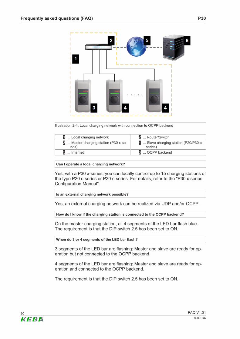
2.9.4 Local charging networkThe following figure shows an example of a local charging network with op-tional connection to an external OCPP backend.
P30Frequently asked questions (FAQ)
FAQ V1.0120© KEBA
Illustration 2-4: Local charging network with connection to OCPP backend
1 ... Local charging network 2 ... Router/Switch3 ... Master charging station (P30 x-se-
ries)4 ... Slave charging station (P20/P30 c-
series)5 ... Internet 6 ... OCPP backend
Can I operate a local charging network?
Yes, with a P30 x-series, you can locally control up to 15 charging stations ofthe type P20 c-series or P30 c-series. For details, refer to the "P30 x-seriesConfiguration Manual".
Is an external charging network possible?
Yes, an external charging network can be realized via UDP and/or OCPP.
How do I know if the charging station is connected to the OCPP backend?
On the master charging station, all 4 segments of the LED bar flash blue.The requirement is that the DIP switch 2.5 has been set to ON.
When do 3 or 4 segments of the LED bar flash?
3 segments of the LED bar are flashing: Master and slave are ready for op-eration but not connected to the OCPP backend.
4 segments of the LED bar are flashing: Master and slave are ready for op-eration and connected to the OCPP backend.
The requirement is that the DIP switch 2.5 has been set to ON.

P30 Frequently asked questions (FAQ)
FAQ V1.01 21© KEBA
Am I permitted to control a master charging station via UDP?
Yes.
What is the anticipated data volume?
The data volume for communication via OCPP 1.5 SOAP is between 10 and50 MB per month. The amount of data depends on the number of chargingsessions.
Which parameters are required for commissioning?
In general:● Total current of the systemFor connection to an OCPP backend:● GSM:
● OCPP URL
● APN data of the provider
● Port for incoming and outgoing communication● LAN/WLAN:
● OCPP URL
What factors should be considered when dimensioning a local charging network?
● Parallel charging● Charging duration● Charging power● Connected load for the entire system
2.9.5 Master/Slave
Is it possible to connect a master charging station and a slave charging station via di-rect cabling?
One master charging station and one slave charging station can be directlyconnected via the Ethernet1 connector (LSA+). The corresponding connec-tion cable must not be crossed. In this case the Ethernet2 connector (RJ45),which is used for debugging purposes, can not be used any more.
A master charging station and multiple slave charging stations must alwaysbe connected via a router or switch.

P30Frequently asked questions (FAQ)
FAQ V1.0122© KEBA
How do I tell when a slave is connected to the master?
● In the web interface● On the LED bar
● Without OCPP connection: On the slave charging station, the left 3 segments of theLED bar will blink green or blink blue if authorization is required.
● With OCPP connection: On the slave charging station, all 4 segments of the LEDbar flash green or blink blue if authorization is required.
How many slave charging stations can I connect to a master charging station?
Up to 15 slave charging stations in a local charging network can be con-nected to a master charging station.
2.9.6 Router/Switch
Which router/switches can be used?
All.
How should be the router/switches be configured?
Information about this can be found in the configuration manual of the router/switch.
What must be observed when using a router?
Port forwarding must be activated.
Am I permitted to attach two master charging stations with activated internal DHCPserver to the same switch?
No. The use of two master charging stations in the same network is only per-mitted if an external DHCP server is used (DHCP function of both master de-activated).
2.9.7 Configuration
Which USB sticks can I use for the configuration?
All USB sticks that are formatted with FAT32 can be used.
InformationFor further information, please refer to the "P30 x-series Configuration Man-ual".
P30 Assistance in case of problems
FAQ V1.01 23© KEBA
3 Assistance in case of problemsThe tables below should help you to identify a problem and perform the rec-ommended measures.
CautionImproper repair can lead to damage of the charging station!Repairs to the charging station may only be carried out by authorized spe-cialists (such as service technicians).
The P30 outputs error messages via the LED bar in the event of faults thatmay occur during operation or after plugging in the charging cable. In addi-tion, these errors are stored with additional in a log file (except for the e-se-ries).
Error displays are shown in the following color combinations:● Blue/red● Red/whiteAppropriate measures can be derived based on the error display.
Whenever an error occurs, it is recommended that you first perform the gen-eral troubleshooting steps.
3.1 General troubleshooting measures
If the charging station indicates an error on the LED bar, general trou-bleshooting steps can be performed first. After each step, it must be checkedwhether the error is still displayed. Specifically, these are the following steps:● Stop the charging procedure by unplugging the vehicle from the
charging station. Then start the charging procedure again.● Restart the charging station: Disconnect the vehicle from the charging
station and switch off the charging station for a short time (30 seconds)via the line circuit breaker.
● Perform a software update.If the error continues to be displayed, the measures from the following tablesmust be carried out.
Contact a service technician
Some errors can only be resolved by a service technician. The measure isthen "Contact service technician". With "service technician" it is meant thedealer or service partner where the charging station was purchased or theelectrician who installed the charging station.

P30Assistance in case of problems
FAQ V1.0124© KEBA
Helpful information
In order for the service technician to perform a quick troubleshooting, he willrequire various information about the charging station. It is recommendedthat you have the following information ready before contacting the servicetechnician:● Product name and serial number of the charging station (on the type
plate)● Installed software version● Activity during which the error occurs● Vehicle brand and model
3.2 Blue/Red error displays
This chapter covers the error messages shown in blue/red on the LED bar.
LED bar Cause MeasureThe switch-on test failed. Thecontactor in the charging stationcould not be switched on.
The charging station is defectiveand must be repaired or re-placed.
An incorrect supply voltage hasbeen detected.
Contact a qualified electrician tocheck the correct connection ofthe charging station to themains.
If the device is correctly con-nected and the error persists:The charging station is defectiveand must be repaired or re-placed.
The charging current is too high.The connected vehicle chargeswith more current than permitted.
Compare the DIP switch settingsof the charging station with themaximum charging current in thetechnical data of the vehicle. Ifthe configuration of the chargingstation is lower, then the configu-ration must be adapted via theDIP switches. The configurationmay only be adapted if this doesnot overload the connection.
Compare the displayed value inthe charging current display ofthe vehicle with the technicaldata of the vehicle. If the value inthe charging current display ishigher, then the vehicle must bechecked in the workshop.
If the check in the workshopdoes not provide a result: Con-tact a service technician
P30 Assistance in case of problems
FAQ V1.01 25© KEBA
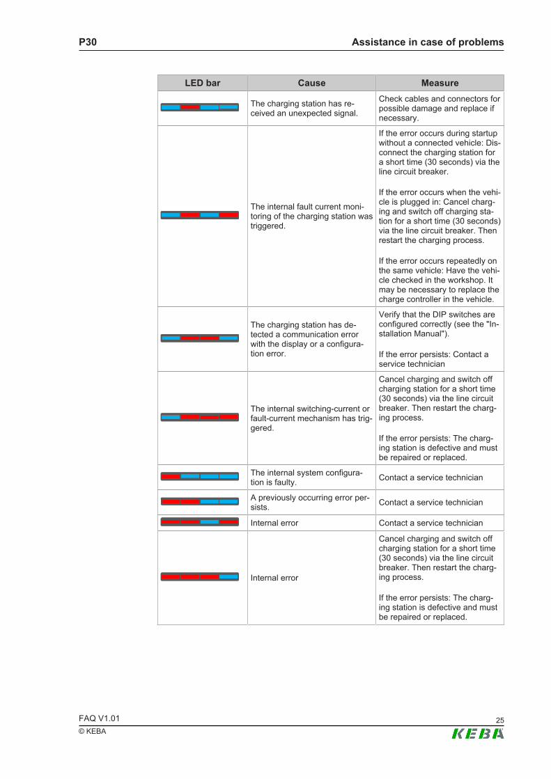
LED bar Cause Measure
The charging station has re-ceived an unexpected signal.
Check cables and connectors forpossible damage and replace ifnecessary.
The internal fault current moni-toring of the charging station wastriggered.
If the error occurs during startupwithout a connected vehicle: Dis-connect the charging station fora short time (30 seconds) via theline circuit breaker.
If the error occurs when the vehi-cle is plugged in: Cancel charg-ing and switch off charging sta-tion for a short time (30 seconds)via the line circuit breaker. Thenrestart the charging process.
If the error occurs repeatedly onthe same vehicle: Have the vehi-cle checked in the workshop. Itmay be necessary to replace thecharge controller in the vehicle.
The charging station has de-tected a communication errorwith the display or a configura-tion error.
Verify that the DIP switches areconfigured correctly (see the "In-stallation Manual").
If the error persists: Contact aservice technician
The internal switching-current orfault-current mechanism has trig-gered.
Cancel charging and switch offcharging station for a short time(30 seconds) via the line circuitbreaker. Then restart the charg-ing process.
If the error persists: The charg-ing station is defective and mustbe repaired or replaced.
The internal system configura-tion is faulty. Contact a service technician
A previously occurring error per-sists. Contact a service technician
Internal error Contact a service technician
Internal error
Cancel charging and switch offcharging station for a short time(30 seconds) via the line circuitbreaker. Then restart the charg-ing process.
If the error persists: The charg-ing station is defective and mustbe repaired or replaced.

P30Assistance in case of problems
FAQ V1.0126© KEBA
LED bar Cause Measure
Internal error
Disconnect the vehicle from thecharging station and restart thecharging process.
If a software update is running:Software update has failed.Download the software updateagain.
If the error persists: Contact aservice technician
3.3 Red/White error displays
This chapter covers the error messages shown in red/white on the LED bar.
LED bar Cause MeasureThe plug was pulled out of thesocket during charging or theplug was not properly locked andreleased from the socket duringcharging.
Disconnect plug and reconnect,paying attention to the correctlocking.
The plug was not recognized. Check if the plug is compliantwith the standard.
Overtemperature shutdown: Thepermissible temperature in thecharging station has been ex-ceeded.
Disconnect the plug and wait un-til the charging station hascooled down.
If the error occurs repeatedly:Check that the device ismounted in a suitable place.
The plug could not be locked.
Unplug the plug and quickly plugit in again.
If the problem persists, check thefollowing: Contamination of thesocket; use of a standard-com-pliant plug; mechanical damageof the plug; cable defect.
The charging station has not de-tected an electric vehicle butrather a unauthorized consumer.Only standard-compliant electri-cally operated vehicles may becharged.
Remove the unauthorized con-sumer and restart the chargingprocess.
The charging station is in com-missioning mode.
Check the DIP switch settings forcorrect configuration and restartthe charging process (see the"Installation Manual").

P30 Assistance in case of problems
FAQ V1.01 27© KEBA
LED bar Cause Measure
The charging station has de-tected a short circuit.
Check cable and plug for dam-age and replace defective com-ponent.
If the error persists: Contact aservice technician
The charging station has de-tected a configuration error.
Check the DIP switch settings forcorrect configuration and restartthe charging process (see the"Installation Manual").
The charging station has de-tected an invalid cable. For com-patibility reasons, the chargingstation does not accept chargingcables with a charging current of13 A or less.
Use a charging cable with ahigher charging current.

P30Diagnostic options
FAQ V1.0128© KEBA
4 Diagnostic optionsThis chapter provides in-depth information to help service technicians diag-nose and troubleshoot.
It is recommended you perform the general measures for troubleshootingfirst, see 3.1 General troubleshooting measures.
Log file
Details about the error messages can be found in the log file (except for thee-series). There the error history and detailed information about the errorscan be called up in the log file.
Depending on the device version, the log file can be downloaded in the fol-lowing ways:● Via the web interface● With a USB stick (x-series only)Via the web interface● P30 x-series: The log files can be viewed and downloaded in the "Sys-
tem" area under "Logging".● All other P30 series: The logging can be viewed in the web interface and
copied from there.With a USB stick (x-series only)
An empty USB stick is required. For downloading, the USB stick must beconnected to the charging station. After this, the log files are automaticallyloaded onto the USB stick. When the download is complete, the chargingstation indicates that the USB stick can be removed.
Determination of the error group
The errors are displayed in the log file via an error code. The position on thefar right of the error code indicates to which error group an error code be-longs. The error group can be calculated from the error display on the LEDbar.
Each segment on the LED bar has a specific significance:
LED segment ValueS1 8
S2 4
S3 2
S4 1
P30 Diagnostic options
FAQ V1.01 29© KEBA
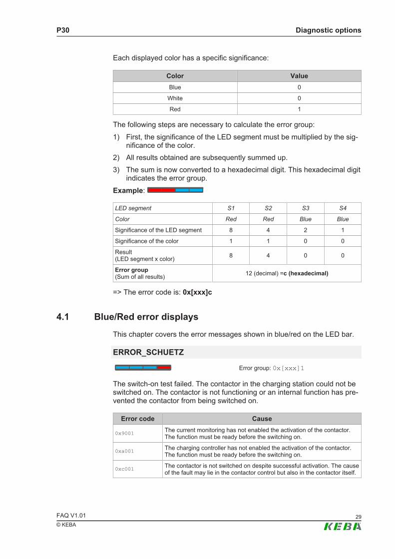
Each displayed color has a specific significance:
Color ValueBlue 0
White 0
Red 1
The following steps are necessary to calculate the error group:1) First, the significance of the LED segment must be multiplied by the sig-
nificance of the color.2) All results obtained are subsequently summed up.3) The sum is now converted to a hexadecimal digit. This hexadecimal digit
indicates the error group.Example:
LED segment S1 S2 S3 S4
Color Red Red Blue Blue
Significance of the LED segment 8 4 2 1
Significance of the color 1 1 0 0
Result (LED segment x color) 8 4 0 0
Error group(Sum of all results) 12 (decimal) =c (hexadecimal)
=> The error code is: 0x[xxx]c
4.1 Blue/Red error displays
This chapter covers the error messages shown in blue/red on the LED bar.
ERROR_SCHUETZ
Error group: 0x[xxx]1
The switch-on test failed. The contactor in the charging station could not beswitched on. The contactor is not functioning or an internal function has pre-vented the contactor from being switched on.
Error code Cause
0x9001 The current monitoring has not enabled the activation of the contactor.The function must be ready before the switching on.
0xa001 The charging controller has not enabled the activation of the contactor.The function must be ready before the switching on.
0xc001 The contactor is not switched on despite successful activation. The causeof the fault may lie in the contactor control but also in the contactor itself.

P30Diagnostic options
FAQ V1.0130© KEBA
Measures
The charging station is defective and must be sent in for repair.
ERROR_VOLTAGES
Error group: 0x[xxx]2
An incorrect supply voltage has been detected. The following causes arepossible:● An undervoltage was detected on phase 1: U < 160 V● An overvoltage was detected on one of the three phases: U > 285 V● The energy meter (voltage monitor) does not work. All measured values
of the last 10 seconds were outside the specified tolerance range.Measures
Check the charging station for correct connection to the mains supply.
If the device is correctly connected and the error persists: The charging sta-tion is defective and must be sent in for repair.
ERROR_CURRENT
Error group: 0x[xxx]3
The charging current monitoring has detected too high a charging current.The cause of the overload is most likely to be in the connected vehicle. Thecriterion for the overload safety cut-off is an overcurrent that has been de-tected for at least 8 seconds on at least one phase.
The term overcurrent is defined as follows: I> 120% of the current inputthrough the charging station
Measures
Compare the DIP switch settings of the charging station with the maximumcharging current in the technical data of the vehicle. If the configuration ofthe charging station is lower, then the configuration must be adapted via theDIP switches. The configuration may only be adapted if this does not over-load the connection.
Compare the displayed value in the charging current display of the vehiclewith the technical data of the vehicle. If the value in the charging current dis-play is higher, then the vehicle must be checked in the workshop.
If the check in the workshop does not provide a result: Contact the KEBAsupport.
P30 Diagnostic options
FAQ V1.01 31© KEBA
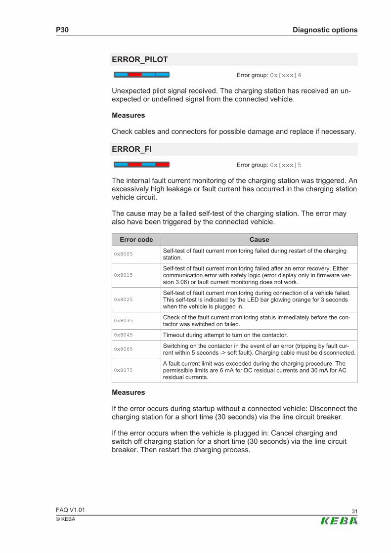
ERROR_PILOT
Error group: 0x[xxx]4
Unexpected pilot signal received. The charging station has received an un-expected or undefined signal from the connected vehicle.
Measures
Check cables and connectors for possible damage and replace if necessary.
ERROR_FI
Error group: 0x[xxx]5
The internal fault current monitoring of the charging station was triggered. Anexcessively high leakage or fault current has occurred in the charging stationvehicle circuit.
The cause may be a failed self-test of the charging station. The error mayalso have been triggered by the connected vehicle.
Error code Cause
0x8005 Self-test of fault current monitoring failed during restart of the chargingstation.
0x8015Self-test of fault current monitoring failed after an error recovery. Eithercommunication error with safety logic (error display only in firmware ver-sion 3.06) or fault current monitoring does not work.
0x8025Self-test of fault current monitoring during connection of a vehicle failed.This self-test is indicated by the LED bar glowing orange for 3 secondswhen the vehicle is plugged in.
0x8035 Check of the fault current monitoring status immediately before the con-tactor was switched on failed.
0x8045 Timeout during attempt to turn on the contactor.
0x8065 Switching on the contactor in the event of an error (tripping by fault cur-rent within 5 seconds -> soft fault). Charging cable must be disconnected.
0x8075A fault current limit was exceeded during the charging procedure. Thepermissible limits are 6 mA for DC residual currents and 30 mA for ACresidual currents.
Measures
If the error occurs during startup without a connected vehicle: Disconnect thecharging station for a short time (30 seconds) via the line circuit breaker.
If the error occurs when the vehicle is plugged in: Cancel charging andswitch off charging station for a short time (30 seconds) via the line circuitbreaker. Then restart the charging process.
P30Diagnostic options
FAQ V1.0132© KEBA
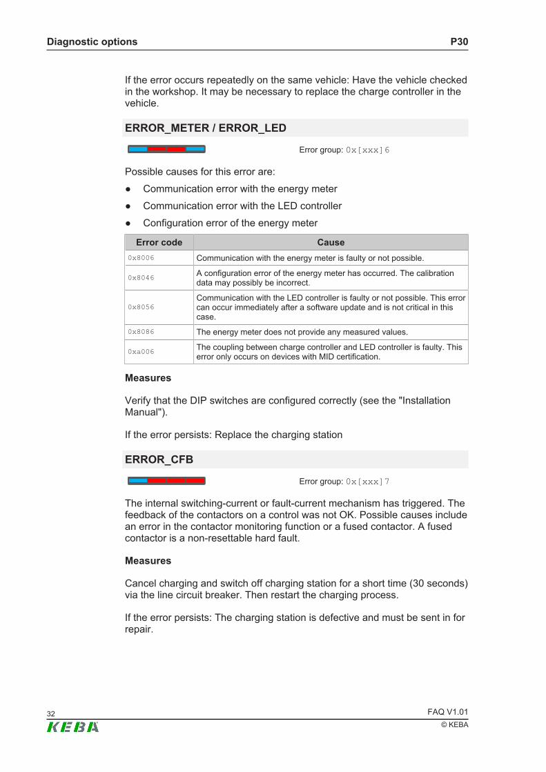
If the error occurs repeatedly on the same vehicle: Have the vehicle checkedin the workshop. It may be necessary to replace the charge controller in thevehicle.
ERROR_METER / ERROR_LED
Error group: 0x[xxx]6
Possible causes for this error are:● Communication error with the energy meter● Communication error with the LED controller● Configuration error of the energy meter
Error code Cause0x8006 Communication with the energy meter is faulty or not possible.
0x8046 A configuration error of the energy meter has occurred. The calibrationdata may possibly be incorrect.
0x8056Communication with the LED controller is faulty or not possible. This errorcan occur immediately after a software update and is not critical in thiscase.
0x8086 The energy meter does not provide any measured values.
0xa006 The coupling between charge controller and LED controller is faulty. Thiserror only occurs on devices with MID certification.
Measures
Verify that the DIP switches are configured correctly (see the "InstallationManual").
If the error persists: Replace the charging station
ERROR_CFB
Error group: 0x[xxx]7
The internal switching-current or fault-current mechanism has triggered. Thefeedback of the contactors on a control was not OK. Possible causes includean error in the contactor monitoring function or a fused contactor. A fusedcontactor is a non-resettable hard fault.
Measures
Cancel charging and switch off charging station for a short time (30 seconds)via the line circuit breaker. Then restart the charging process.
If the error persists: The charging station is defective and must be sent in forrepair.

P30 Diagnostic options
FAQ V1.01 33© KEBA
Note for devices with firmware version prior to 3.06: Communication with thesafety logic of the charging station may abort at irregular intervals. The errorcan be remedied in such cases by restarting the charging station. Since theerror can occur repeatedly with old firmware versions, a software update isrequired.
ERROR_CONFIG
Error group: 0x[xxx]8
The internal system configuration is faulty.
Measures
Replace the charging station.
ERROR_PERSIST
Error group: 0x[xxx]c
A previously occurring error persists despite running through the automaticerror reaction. The error is displayed on the LED bar alternately with the trig-gering error if the original error can no longer be reset.
Measures
Contact the KEBA support.
ERROR_CON
Error group: 0x[xxx]d
Internal error
Measures
Contact the KEBA support.
ERROR_STATE
Error group: 0x[xxx]e
The internal charge controller has requested an illegal status change.
Measures
Cancel charging and switch off charging station for a short time (30 seconds)via the line circuit breaker. Then restart the charging process.
If the error persists: The charging station is defective and must be sent in forrepair.

P30Diagnostic options
FAQ V1.0134© KEBA
ERROR_SYSTEM
Error group: 0x[xxx]f
The communication with the charging controller of the charging station is notpossible or there is an error in the firmware.
Measures
Disconnect the vehicle from the charging station and restart the chargingprocess.
If a software update is running: Software update has failed. Download thesoftware update again.
If the error persists: Contact the KEBA support.
4.2 Red/White error displays
This chapter covers the error messages shown in red/white on the LED bar.
AUTARK_PLUG_LOST
Error group: 0x[xxx]1
The plug was pulled out of the socket during charging or the plug was notproperly locked and released from the socket during charging.
Measures
Disconnect plug and reconnect, paying attention to the correct locking.
AUTARK_PLUG_UNDEF
Error group: 0x[xxx]2
The plug was not recognized.
Measures
Check if the plug is compliant with the standard.
AUTARK_OVERHEAT
Error group: 0x[xxx]3
Overtemperature shutdown: The permissible temperature in the chargingstation has been exceeded.
Measures

P30 Diagnostic options
FAQ V1.01 35© KEBA
Disconnect the plug and wait until the charging station has cooled down.
If the error occurs repeatedly: Check that the device is mounted in a suitableplace.
AUTARK_LOCK_FAILED
Error group: 0x[xxx]4
The plug could not be locked.
Measures
Unplug the plug and quickly plug it in again.
If the problem persists, check the following:● Dirt in the socket● Use of a standard-compliant plug● Mechanical damage of the plug● Defect of the cable
AUTARK_OHMIC_LOAD
Error group: 0x[xxx]5
The charging station has not detected an electric vehicle but rather a unau-thorized consumer. Only standard-compliant electrically operated vehiclesmay be charged.
Measures
Remove the unauthorized consumer and restart the charging process.
AUTARK_IBN_MODE
Error group: 0x[xxx]7
The charging station is in commissioning mode.
Measures
Check the DIP switch settings for correct configuration and restart the charg-ing process (see the "Installation Manual").
AUTARK_SHORT_CIRCUIT
Error group: 0x[xxx]8
The charging station has detected a short circuit.

P30Diagnostic options
FAQ V1.0136© KEBA
Measures
Check cable and plug for damage and replace defective component.
If the error persists: Contact the KEBA support.
AUTARK_CONFIG_ERR
Error group: 0x[xxx]9
The charging station has detected a configuration error.
Measures
Check the DIP switch settings for correct configuration and restart the charg-ing process (see the "Installation Manual").
AUTARK_13A_ERROR
Error group: 0x[xxx]a
The charging station has detected an invalid cable. For compatibility rea-sons, the charging station does not accept charging cables with a chargingcurrent of 13 A or less.
Measures
Use a charging cable with a higher charging current.
P30 Index
FAQ V1.01 37© KEBA
Index
AAPN ......................................................... 19Auto-recovery .......................................... 12
CCalibrated meter ...................................... 12Charging current
Controlling........................................... 11Charging management ............................ 19
Dimensioning ...................................... 21Charging network .................................... 19Charging power ......................................... 9Check ........................................................ 9Connected load ....................................... 10Connections
Ethernet .............................................. 18
DData volume ............................................ 21DC fault current monitoring ..................... 12DC fault detection.................................... 12DC leakage.............................................. 12DHCP server ........................................... 18
Activate ............................................... 18
EEnergy display......................................... 12Equipment ................................................. 9Error display ............................................ 23Ethernet-connection ................................ 18
FFloor-mounted column ............................ 11
GGarage .................................................... 11GSM ........................................................ 19
IInstallation
Floor-mounted column........................ 11IP address
Determine ........................................... 14Range ................................................. 18Setup .................................................. 13
LLAN ......................................................... 19LED bar ................................................... 20Line circuit breaker .................................... 9Log file ..................................................... 17
MMAC address........................................... 13Master ............................................... 21, 22
Connection state................................. 20Meter reading display .............................. 12
NNetwork connection................................. 18
OOCPP backend
Connection.......................................... 18Connection state................................. 20
Opening the power supply terminal ......... 10Operational readiness ............................. 11
PParameter................................................ 21

P30Index
FAQ V1.0138© KEBA
RResidual-current device............................. 9Restart ..................................................... 12RFID ........................................................ 13Router...................................................... 22
SSecured against
Line circuit breaker ............................... 9Residual-current device ........................ 9
Service technician ................................... 23SIM card .................................................. 19Slave ................................................. 21, 22Software
Update ................................................ 15Version................................................ 14
Switch...................................................... 22
UUDP......................................................... 21Update..................................................... 15USB stick ................................................. 22
WWLAN access point (hotspot) .................. 19