page 1 of 400 bookmark listings - the national board of ... 4 attachment bundle... · bookmark...
TRANSCRIPT
Bookmark Listings Listing of Bookmarks (page# 1) Table of Contents(page# 2) Roster SC 4 Dec 2015(page# 3) Daniel Marek Resume(page# 5) SC 4 Attachment Bundle.pdf
(page# 5) IN15-1401 12-15-15 Besserman(page# 6) NB11-0401 Proposed Part 3 Changes 12-11-15 Besserman(page# 301) NB11-0401 Proposed Part 4 12-11-15 Besserman(page# 384) NB11-0401 SC PRD Comments 12-11-15 Besserman(page# 385) NB11-0401 SC RA Comments 12-11-15 Besserman(page# 386) NB11-0401 Webb Comments 12-11-15 Besserman(page# 387) NB15-0103 July Meeting Attachment 12-11-15 Besserman(page# 389) NB15-0307 July Meeting Attachment 12-11-15 Besserman(page# 394) NB15-1001 NB15-1002 NB15-1003 NB15-1004 12-11-15 Besserman(page# 395) NB15-2401 Diagram 12-11-15 Besserman(page# 396) NB15-2401 July Meeting Attachment 12-11-15 Besserman(page# 397) NB15-2401 Supplementary Information 12-11-15 Besserman(page# 400) NB15-3201 12-9-15 Besserman
Page 1 of 400
Page 1 of 400

Page 2 of 400
Page 2 of 400

Daniel T. Marek
21000 Brookpark Rd Cleveland, OH 44135 (216) 433–5494 [email protected] Summary An engineering professional with almost 20 years of code compliance, design, application and
testing experience in areas ranging from pressure vessels/process piping, industrial components and mobile HVAC while insuring product/process quality, excellent customer service, and team work.
Professional Experience
MAINTHIA TECHNOLOGIES INCORPORATED – Middleburg Hts, OH 04/2007 – Present Support Service Contractor to the NASA Glenn Research Center – Cleveland, OH
Senior Pressure Systems Engineer - (Pressure Systems Office) • Responsible for conducting all phases of pressure vessel and pressure system (PV\S)
certification in accordance with NASA NPD 8710.5, NASA STD 8719.17 and numerous national consensus codes including ASME B&PV Section VIII Div I & II, ASME B31.3, NBIC, EJMA, DOT and API
• Responsible for performing pressure vessel and pressure system certification utilizing the following skill sets:
o Recommendation of non-destructive examinations o Field analysis of system/pressure vessel configuration to ensure code compliance o Performance of calculations in support of pressure vessel and pressure system
certification Determination of maximum allowable working pressure and mechanical
integrity Fracture mechanics flaw analysis Relief device capacity sizing and vent system analysis Piping flexibility analysis
o Determination of inspection and recertification frequencies based upon mechanical integrity calculations and remaining life analysis
o Working with pressure vessel/pressure system owners to ensure all issues found during certification are corrected and required documentation is archived
o Preparation of risk assessment reports (RACs) • Responsible for coordinating piping and pressure vessel repairs as required in support of
certifying the NASA Glenn Research Center’s 40# Combustion Air System and the annual Central Process System header inspections. Responsibilities include the following:
o Preparation of a scope of work for each repair o Sourcing and soliciting of competitive bids for presentation to NASA system
owner o Coordination of environmental abatement as required o Coordination of required health and safety plan and hot work/excavation permits o Daily worksite inspections along with a final inspection to ensure contract
requirements were met • Have worked with the NASA Glenn Research Center’s Facilities Division since
conception of the following new pressure systems to ensure code compliance is maintained during both design and fabrication:
o Service air compressor SA-24 o Combustion air dehydrator TD5
Page 3 of 400
Page 3 of 400

NOSHOK, INCORPORATED – Berea, OH 10/1999 – 03/2007 Design Engineer - (Valve and Instrumentation Products)
• Developed and designed new products from conception to production utilizing the following skill sets:
o Created 3D models using PTC Pro/Engineer Wildfire 2.0 o Created detailed drawings for both individual components and final assemblies o Created various macros in Microsoft Excel for mechanical design calculations o Utilized Pro/Engineer Mechanica Structural Simulation Software for analysis of
structural integrity • Performed high pressure burst, life cycle, and control valve flow tests as part of product
development • Developed a receiving inspection program for incoming components
EAGLE ENGINEERING & MANUFACTURING - Cleveland, OH 03/1999 – 07/1999
Project Engineer – (Aftermarket / OEM HVAC Systems) • Responsible for final design and production release of an aftermarket medium duty
rooftop mobile A/C system. PARKER HANNIFIN CORPORATION – Mayfield Hts, OH 12/1995 – 03/1999
Application Engineer – Heavy Truck / Off Road Business Unit (Batesville, MS) 9/98-3/99 • Responsible for application engineering and pricing of mobile A/C plumbing for Case IH
(US Models) and John Deere programs from initial concept to production release Quality Engineer / Launch Coordinator – Plant Quality Department (Batesville, MS) 3/98-9/98
• Responsible for managing program launches/pilot runs from the release of production prints.
• Supervised a staff of six in-process quality control inspectors over two production shifts Application Engineer – Chrysler Business Unit (Troy, MI) 1/97-3/98
• Responsible for various engineering projects for mobile A/C plumbing, expansion valves, receiver driers, and electric vehicle-cooling modules in support of various Chrysler product lines.
Project Engineer – Dodge Truck Climate Control (Detroit, MI) 12/95-12/96 • Contracted thru Parker Hannifin to Chrysler Corporation – Jeep & Truck Division • Responsible for multiple projects to analyze and improve the function and performance
of the Dodge Ram Truck’s HVAC System
Education Bachelor of Mechanical Engineering Technology - University of Toledo, Toledo, OH 1997
Page 4 of 400
Page 4 of 400

Page 5 of 400
Page 5 of 400
2015 National Board Digital Library “Single User” Instructional License Agreement
Carefully read the following terms and conditions before using the pdf file
COPYRIGHT & LICENSE
The National Board Inspection Code (NBIC) is a copyrighted publication of the National Board of Boiler and Pressure Vessel Inspectors. As such, this copyright extends to any/all published versions of the NBIC including printed copies or Web subscription.
You do not own this copy of the NBIC; the National Board has licensed this copy to you for the use described herein. This pdf file is licensed for use by a single user. “Use” means loaded in temporary memory or permanent storage on the computer. The National Board reserves all rights not expressly granted to you.
I understand that I am being provided a pdf file containing the 2015 NBIC in consideration of my representation and/or agreement that:
• I may photocopy the contents solely for my own use but I am prohibited from making such photocopy available to others for copying.
• I will not make the NBIC electronically available through downloading, file sharing or through any other means.• Additionally, I will not loan the pdf file for the purpose of photocopy, electronic download, file sharing or for any other copying
means.• I understand that any unauthorized duplication of the NBIC through my actions, either deliberate or unintentional, directly or
indirectly, may also subject me to a claim of copyright infringement.• I further understand that any attempt to electronically alter information in the file renders this device legally void and unusable for
all future reference.
TERM
These terms and conditions are effective until terminated.
LIMITED WARRANTY
The files are provided ‘as is’ without warranty of any kind, either expressed or implied, including but not limited to implied warranties of merchantability and fitness for any particular purpose.
The National Board does not warrant that the functions contained in the files will meet your requirements or that the operation of the files will be uninterrupted or error free. You assume responsibility for selecting the software to achieve your intended results, and for the use and results obtained from the software.
LIMITATION OF REMEDIES
In no event will the National Board be liable to you for any damages, including any lost profits, lost savings, or any other incidental or consequential damages arising from the use or inability to use such program even if the National Board has been advised of the possi-bility of such damages, or for any claim by any other party.
Some states do not allow the limitation or exclusion of liability for incidental or consequential damage, so the above exclusion may not apply to you.
GENERAL
This Agreement will be governed by the laws of the state of Ohio.
Should you have any questions concerning this Agreement, you may contact the National Board by writing to The National Board of Boiler and Pressure Vessel Inspectors, 1055 Crupper Avenue, Columbus, Ohio 43229-1183.
"FO
RC
OM
MIT
TEE
US
E
I further understand that any attempt to electronically alter information in the file renders this device legally void and unusable for US
E
I further understand that any attempt to electronically alter information in the file renders this device legally void and unusable for
ON
LY"
licensed for use by a single user. “Use” means loaded in temporary memory or permanent storage on the computer. The National Board
ON
LY"
licensed for use by a single user. “Use” means loaded in temporary memory or permanent storage on the computer. The National Board
Page 6 of 400
Page 6 of 400
"FO
RC
OM
MIT
TEE
US
EO
NLY
"
Page 7 of 400
Page 7 of 400
I
2015NB-23
NATIONAL BOARD INSPECTION CODE 2015 EDITION
DATE OF ISSUE — JULY 1, 2015
This code was developed under procedures accredited as meeting the criteria for American National Stan-dards. The Consensus Committee that approved the code was balanced to ensure that individuals from com-petent and concerned interests had an opportunity to participate. The proposed code was made available for public review and comment, which provided an opportunity for additional public input from industry, academia, regulatory and jurisdictional agencies, and the public-at-large.
The National Board does not “approve,” “rate,” or “endorse” any item, construction, proprietary device, or activity.
The National Board does not take any position with respect to the validity of any patent rights asserted in connection with any items mentioned in this document, and does not undertake to insure anyone utilizing a standard against liability for infringement of any applicable Letters Patent, nor assume any such liability. Us-ers of a code are expressly advised that determination of the validity of any such patent rights, and the risk of infringement of such rights, is entirely their own responsibility.
Participation by federal agency representative(s) or person(s) affiliated with industry is not to be interpreted as government or industry endorsement of this code.
The National Board accepts responsibility for only those interpretations issued in accordance with governing National Board procedures and policies that preclude the issuance of interpretations by individual committee members.
The footnotes in this document are part of this American National Standard.
RR
NR RR
®
The above National Board symbols are registered with the US Patent Office.
“National Board” is the abbreviation for The National Board of Boiler and Pressure Vessel Inspectors.
No part of this document may be reproduced in any form, in an electronic retrieval system or otherwise, without the prior written permission of the publisher.
All charts, graphs, tables, and other criteria that have been reprinted from the ASME Boiler and Pressure Vessel Code, Sections I, IV, VIII, and X are used with the permission of the American Society of Mechanical Engineers. All Rights Reserved.
Library of Congress Catalog Card No. 52-44738 Printed in the United States of America All Rights Reserved
www.nationalboard.org
Copyright © 2015 byTHE NATIONAL BOARD OF BOILER & PRESSURE VESSEL INSPECTORS
All rights reservedPrinted in U.S.A.
"FO
RC
OM
MIT
TEE
US
EO
NLY
"
Page 8 of 400
Page 8 of 400
II
NATIONAL BOARD INSPECTION CODE2015
TABLE OF CONTENTS
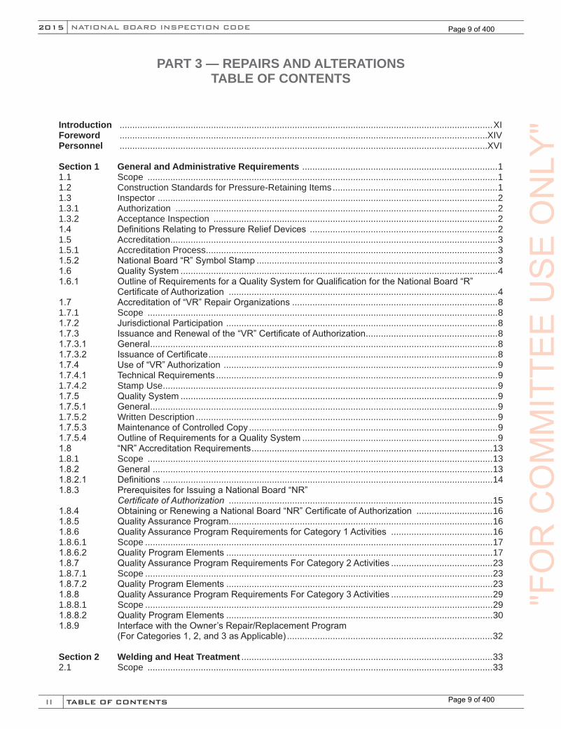
PART 3 — REPAIRS AND ALTERATIONS TABLE OF CONTENTS
Introduction ...................................................................................................................................................XIForeword .................................................................................................................................................XIVPersonnel .................................................................................................................................................XVI
Section 1 General and Administrative Requirements .............................................................................11.1 Scope ..........................................................................................................................................11.2 Construction Standards for Pressure-Retaining Items.................................................................11.3 Inspector ......................................................................................................................................21.3.1 Authorization ...............................................................................................................................21.3.2 Acceptance Inspection ................................................................................................................21.4 DefinitionsRelatingtoPressureReliefDevices ..........................................................................21.5 Accreditation.................................................................................................................................31.5.1 Accreditation Process...................................................................................................................31.5.2 NationalBoard“R”SymbolStamp ...............................................................................................31.6 QualitySystem .............................................................................................................................41.6.1 OutlineofRequirementsforaQualitySystemforQualificationfortheNationalBoard“R” CertificateofAuthorization ..........................................................................................................41.7 Accreditationof“VR”RepairOrganizations .................................................................................81.7.1 Scope ..........................................................................................................................................81.7.2 JurisdictionalParticipation...........................................................................................................81.7.3 IssuanceandRenewalofthe“VR”CertificateofAuthorization....................................................81.7.3.1 General.........................................................................................................................................81.7.3.2 IssuanceofCertificate..................................................................................................................81.7.4 Useof“VR”Authorization............................................................................................................91.7.4.1 TechnicalRequirements ...............................................................................................................91.7.4.2 Stamp Use....................................................................................................................................91.7.5 QualitySystem .............................................................................................................................91.7.5.1 General.........................................................................................................................................91.7.5.2 Written Description .......................................................................................................................91.7.5.3 MaintenanceofControlledCopy ..................................................................................................91.7.5.4 OutlineofRequirementsforaQualitySystem .............................................................................91.8 “NR”AccreditationRequirements...............................................................................................131.8.1 Scope ........................................................................................................................................131.8.2 General......................................................................................................................................131.8.2.1 Definitions..................................................................................................................................141.8.3 PrerequisitesforIssuingaNationalBoard“NR”
Certificate of Authorization ........................................................................................................151.8.4 ObtainingorRenewingaNationalBoard“NR”CertificateofAuthorization ..............................161.8.5 QualityAssuranceProgram........................................................................................................161.8.6 QualityAssuranceProgramRequirementsforCategory1Activities ........................................161.8.6.1 Scope .........................................................................................................................................171.8.6.2 QualityProgramElements .........................................................................................................171.8.7 QualityAssuranceProgramRequirementsForCategory2Activities ........................................231.8.7.1 Scope .........................................................................................................................................231.8.7.2 QualityProgramElements .........................................................................................................231.8.8 QualityAssuranceProgramRequirementsForCategory3Activities ........................................291.8.8.1 Scope .........................................................................................................................................291.8.8.2 QualityProgramElements .........................................................................................................301.8.9 InterfacewiththeOwner’sRepair/ReplacementProgram (ForCategories1,2,and3asApplicable) .................................................................................32
Section 2 Welding and Heat Treatment ...................................................................................................332.1 Scope ........................................................................................................................................33
"FO
RC
OM
MIT
TEE
US
EO
NLY
"
Page 9 of 400
Page 9 of 400

III
NB-23 2015
TABLE OF CONTENTS
2.2 Welding .....................................................................................................................................332.2.1 WeldingProcedureSpecifications.............................................................................................332.2.2 StandardWeldingProcedureSpecifications .............................................................................332.2.3 PerformanceQualification .........................................................................................................332.2.4 WeldingRecords .......................................................................................................................332.2.5 Welder’sIdentification ...............................................................................................................332.2.6 Welder’sContinuity ...................................................................................................................342.2.6.1 Welder’sContinuityRecords ......................................................................................................342.3 StandardWeldingProcedureSpecifications .............................................................................342.4 AWS Reference Standards .......................................................................................................402.5 Heat Treatment ..........................................................................................................................402.5.1 Preheating .................................................................................................................................402.5.2 PostweldHeatTreatment(PWHT) .............................................................................................422.5.3 AlternativeWeldingMethodsWithoutPostweldHeatTreatment ...............................................442.5.3.1 WeldingMethod1 ..................................................................................................................... 452.5.3.2 WeldingMethod2 .....................................................................................................................462.5.3.3 WeldingMethod3 .....................................................................................................................472.5.3.4 WeldingMethod4 .....................................................................................................................482.5.3.5 WeldingMethod5 .....................................................................................................................492.5.3.6 WeldingMethod6 .....................................................................................................................50
Section 3 Requirements for Repairs and Alterations ............................................................................523.1 Scope ........................................................................................................................................523.2 GeneralRequirementsforRepairsandAlterations...................................................................523.2.1 MaterialRequirementsforRepairsandAlterations...................................................................523.2.2 ReplacementParts....................................................................................................................523.2.3 Drawings ...................................................................................................................................533.2.4 DesignRequirementsforRepairsandAlterations ....................................................................533.2.5 Calculations...............................................................................................................................533.2.6 Reference to Other Codes and Standards ................................................................................533.2.7 ChangeofService.....................................................................................................................543.3 Repairs to Pressure-Retaining Items ........................................................................................543.3.1 Defect Repairs ...........................................................................................................................543.3.2 Routine Repairs .........................................................................................................................543.3.3 ExamplesofRepairs .................................................................................................................553.3.4 Repair Methods .........................................................................................................................563.3.4.1 Scope ........................................................................................................................................563.3.4.2 Defect Repairs ...........................................................................................................................563.3.4.3 Wasted Areas ............................................................................................................................593.3.4.4 SealWelding .............................................................................................................................633.3.4.5 Re-EndingorPiecingPipesorTubes .......................................................................................653.3.4.6 Patches .....................................................................................................................................663.3.4.7 Stays .........................................................................................................................................683.3.4.8 RepairofPressure-RetainingItemsWithoutCompleteRemovalofDefects .............................683.3.4.9 TubePlugginginFiretubeBoilers ..............................................................................................693.3.5 RepairofASMESectionVIII,Division2or3,PressureVessels...............................................693.3.5.1 Scope ........................................................................................................................................693.3.5.2 RepairPlan................................................................................................................................693.4 Alterations .................................................................................................................................703.4.1 Re-Rating ..................................................................................................................................703.4.2 AlterationsBasedonAllowableStressValues ..........................................................................703.4.3 ExamplesofAlterations.............................................................................................................713.4.4 AlterationofASMECodeSectionVIII,Division2or3,PressureVessels.................................713.4.4.1 AlterationPlan ...........................................................................................................................71
Section 4 Examination and Testing .........................................................................................................734.1 Scope ........................................................................................................................................734.2 NondestructiveExamination......................................................................................................734.3 PressureGages,Measurement,Examination,andTestEquipment.........................................73
"FO
RC
OM
MIT
TEE
US
EO
NLY
"
Page 10 of 400
Page 10 of 400
IV
NATIONAL BOARD INSPECTION CODE2015
TABLE OF CONTENTS
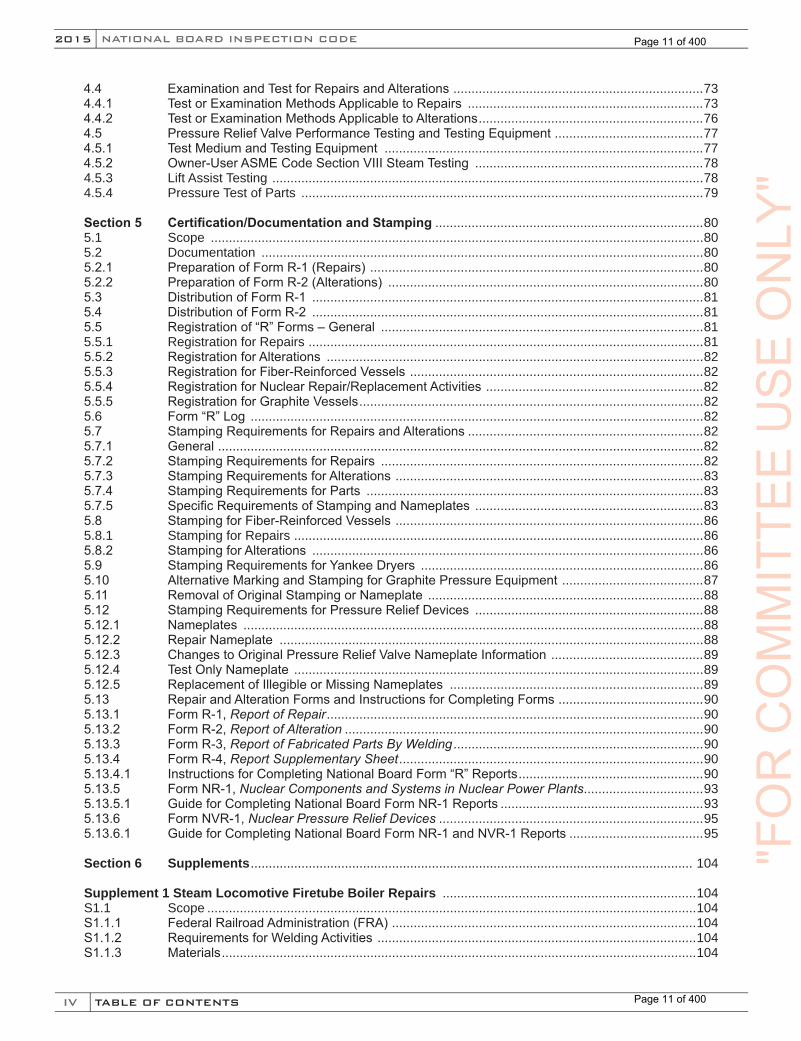
4.4 ExaminationandTestforRepairsandAlterations.....................................................................734.4.1 TestorExaminationMethodsApplicabletoRepairs .................................................................734.4.2 TestorExaminationMethodsApplicabletoAlterations..............................................................764.5 PressureReliefValvePerformanceTestingandTestingEquipment.........................................774.5.1 TestMediumandTestingEquipment ........................................................................................774.5.2 Owner-UserASMECodeSectionVIIISteamTesting ...............................................................784.5.3 Lift Assist Testing .......................................................................................................................784.5.4 Pressure Test of Parts ...............................................................................................................79
Section 5 Certification/Documentation and Stamping ..........................................................................805.1 Scope ........................................................................................................................................805.2 Documentation ..........................................................................................................................805.2.1 PreparationofFormR-1(Repairs)............................................................................................805.2.2 PreparationofFormR-2(Alterations) .......................................................................................805.3 DistributionofFormR-1 ............................................................................................................815.4 DistributionofFormR-2 ............................................................................................................815.5 Registrationof“R”Forms–General .........................................................................................815.5.1 Registration for Repairs .............................................................................................................815.5.2 RegistrationforAlterations ........................................................................................................825.5.3 RegistrationforFiber-ReinforcedVessels.................................................................................825.5.4 RegistrationforNuclearRepair/ReplacementActivities............................................................825.5.5 RegistrationforGraphiteVessels...............................................................................................825.6 Form“R”Log .............................................................................................................................825.7 StampingRequirementsforRepairsandAlterations .................................................................825.7.1 General......................................................................................................................................825.7.2 StampingRequirementsforRepairs .........................................................................................825.7.3 StampingRequirementsforAlterations.....................................................................................835.7.4 StampingRequirementsforParts .............................................................................................835.7.5 SpecificRequirementsofStampingandNameplates ...............................................................835.8 StampingforFiber-ReinforcedVessels.....................................................................................865.8.1 Stamping for Repairs .................................................................................................................865.8.2 StampingforAlterations ............................................................................................................865.9 StampingRequirementsforYankeeDryers ..............................................................................865.10 AlternativeMarkingandStampingforGraphitePressureEquipment.......................................875.11 RemovalofOriginalStampingorNameplate ............................................................................885.12 StampingRequirementsforPressureReliefDevices ...............................................................885.12.1 Nameplates ...............................................................................................................................885.12.2 RepairNameplate .....................................................................................................................885.12.3 ChangestoOriginalPressureReliefValveNameplateInformation..........................................895.12.4 TestOnlyNameplate .................................................................................................................895.12.5 ReplacementofIllegibleorMissingNameplates ......................................................................895.13 RepairandAlterationFormsandInstructionsforCompletingForms........................................905.13.1 FormR-1,Report of Repair........................................................................................................905.13.2 FormR-2,Report of Alteration ...................................................................................................905.13.3 FormR-3,Report of Fabricated Parts By Welding .....................................................................905.13.4 FormR-4,Report Supplementary Sheet....................................................................................905.13.4.1 InstructionsforCompletingNationalBoardForm“R”Reports...................................................905.13.5 FormNR-1,Nuclear Components and Systems in Nuclear Power Plants.................................935.13.5.1 GuideforCompletingNationalBoardFormNR-1Reports ........................................................935.13.6 FormNVR-1,Nuclear Pressure Relief Devices .........................................................................955.13.6.1 GuideforCompletingNationalBoardFormNR-1andNVR-1Reports .....................................95
Section 6 Supplements.......................................................................................................................... 104
Supplement 1 Steam Locomotive Firetube Boiler Repairs ......................................................................104S1.1 Scope .......................................................................................................................................104S1.1.1 FederalRailroadAdministration(FRA)....................................................................................104S1.1.2 RequirementsforWeldingActivities ........................................................................................104S1.1.3 Materials...................................................................................................................................104
"FO
RC
OM
MIT
TEE
US
EO
NLY
"
Page 11 of 400
Page 11 of 400
V
NB-23 2015
TABLE OF CONTENTS
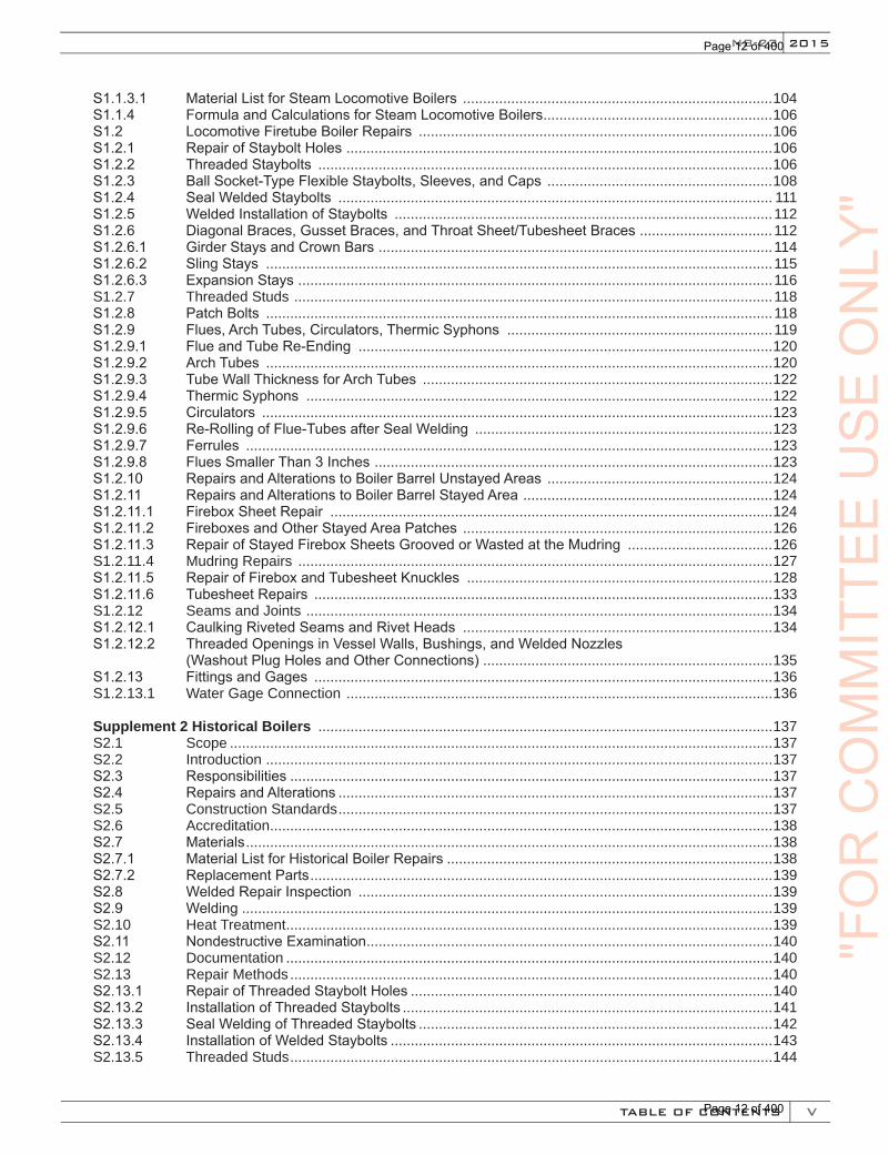
S1.1.3.1 MaterialListforSteamLocomotiveBoilers .............................................................................104S1.1.4 FormulaandCalculationsforSteamLocomotiveBoilers.........................................................106S1.2 LocomotiveFiretubeBoilerRepairs ........................................................................................106S1.2.1 RepairofStayboltHoles..........................................................................................................106S1.2.2 ThreadedStaybolts .................................................................................................................106S1.2.3 BallSocket-TypeFlexibleStaybolts,Sleeves,andCaps ........................................................108S1.2.4 SealWeldedStaybolts ............................................................................................................ 111S1.2.5 WeldedInstallationofStaybolts ..............................................................................................112S1.2.6 DiagonalBraces,GussetBraces,andThroatSheet/TubesheetBraces.................................112S1.2.6.1 GirderStaysandCrownBars..................................................................................................114S1.2.6.2 SlingStays ..............................................................................................................................115S1.2.6.3 ExpansionStays......................................................................................................................116S1.2.7 Threaded Studs .......................................................................................................................118S1.2.8 PatchBolts ..............................................................................................................................118S1.2.9 Flues,ArchTubes,Circulators,ThermicSyphons ..................................................................119S1.2.9.1 FlueandTubeRe-Ending .......................................................................................................120S1.2.9.2 ArchTubes ..............................................................................................................................120S1.2.9.3 TubeWallThicknessforArchTubes .......................................................................................122S1.2.9.4 ThermicSyphons ....................................................................................................................122S1.2.9.5 Circulators ...............................................................................................................................123S1.2.9.6 Re-RollingofFlue-TubesafterSealWelding ..........................................................................123S1.2.9.7 Ferrules ...................................................................................................................................123S1.2.9.8 FluesSmallerThan3Inches...................................................................................................123S1.2.10 RepairsandAlterationstoBoilerBarrelUnstayedAreas ........................................................124S1.2.11 RepairsandAlterationstoBoilerBarrelStayedArea..............................................................124S1.2.11.1 FireboxSheetRepair ..............................................................................................................124S1.2.11.2 FireboxesandOtherStayedAreaPatches .............................................................................126S1.2.11.3 RepairofStayedFireboxSheetsGroovedorWastedattheMudring ....................................126S1.2.11.4 Mudring Repairs ......................................................................................................................127S1.2.11.5 RepairofFireboxandTubesheetKnuckles ............................................................................128S1.2.11.6 TubesheetRepairs ..................................................................................................................133S1.2.12 Seams and Joints ....................................................................................................................134S1.2.12.1 CaulkingRivetedSeamsandRivetHeads .............................................................................134S1.2.12.2 ThreadedOpeningsinVesselWalls,Bushings,andWeldedNozzles (WashoutPlugHolesandOtherConnections)........................................................................135S1.2.13 FittingsandGages ..................................................................................................................136S1.2.13.1 Water Gage Connection ..........................................................................................................136
Supplement 2 Historical Boilers .................................................................................................................137S2.1 Scope .......................................................................................................................................137S2.2 Introduction ..............................................................................................................................137S2.3 Responsibilities ........................................................................................................................137S2.4 RepairsandAlterations ............................................................................................................137S2.5 Construction Standards............................................................................................................137S2.6 Accreditation.............................................................................................................................138S2.7 Materials...................................................................................................................................138S2.7.1 MaterialListforHistoricalBoilerRepairs .................................................................................138S2.7.2 ReplacementParts...................................................................................................................139S2.8 WeldedRepairInspection .......................................................................................................139S2.9 Welding ....................................................................................................................................139S2.10 Heat Treatment.........................................................................................................................139S2.11 NondestructiveExamination.....................................................................................................140S2.12 Documentation .........................................................................................................................140S2.13 Repair Methods ........................................................................................................................140S2.13.1 RepairofThreadedStayboltHoles ..........................................................................................140S2.13.2 InstallationofThreadedStaybolts ............................................................................................141S2.13.3 SealWeldingofThreadedStaybolts ........................................................................................142S2.13.4 InstallationofWeldedStaybolts ...............................................................................................143S2.13.5 Threaded Studs........................................................................................................................144
"FO
RC
OM
MIT
TEE
US
EO
NLY
"
Page 12 of 400
Page 12 of 400
VI
NATIONAL BOARD INSPECTION CODE2015
TABLE OF CONTENTS
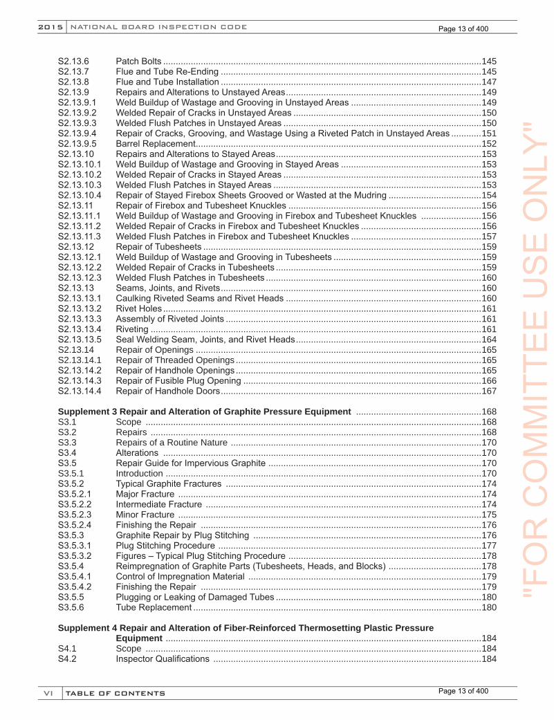
S2.13.6 PatchBolts ...............................................................................................................................145S2.13.7 FlueandTubeRe-Ending ........................................................................................................145S2.13.8 FlueandTubeInstallation ........................................................................................................147S2.13.9 RepairsandAlterationstoUnstayedAreas..............................................................................149S2.13.9.1 WeldBuildupofWastageandGroovinginUnstayedAreas ....................................................149S2.13.9.2 WeldedRepairofCracksinUnstayedAreas ...........................................................................150S2.13.9.3 WeldedFlushPatchesinUnstayedAreas ...............................................................................150S2.13.9.4 RepairofCracks,Grooving,andWastageUsingaRivetedPatchinUnstayedAreas ............151S2.13.9.5 BarrelReplacement..................................................................................................................152S2.13.10 RepairsandAlterationstoStayedAreas..................................................................................153S2.13.10.1 WeldBuildupofWastageandGroovinginStayedAreas ........................................................153S2.13.10.2 WeldedRepairofCracksinStayedAreas ...............................................................................153S2.13.10.3 WeldedFlushPatchesinStayedAreas ...................................................................................153S2.13.10.4 RepairofStayedFireboxSheetsGroovedorWastedattheMudring .....................................154S2.13.11 RepairofFireboxandTubesheetKnuckles .............................................................................156S2.13.11.1 WeldBuildupofWastageandGroovinginFireboxandTubesheetKnuckles ........................156S2.13.11.2 WeldedRepairofCracksinFireboxandTubesheetKnuckles ................................................156S2.13.11.3 WeldedFlushPatchesinFireboxandTubesheetKnuckles ....................................................157S2.13.12 RepairofTubesheets ...............................................................................................................159S2.13.12.1 WeldBuildupofWastageandGroovinginTubesheets ...........................................................159S2.13.12.2 WeldedRepairofCracksinTubesheets ..................................................................................159S2.13.12.3 WeldedFlushPatchesinTubesheets ......................................................................................160S2.13.13 Seams,Joints,andRivets........................................................................................................160S2.13.13.1 CaulkingRivetedSeamsandRivetHeads ..............................................................................160S2.13.13.2 RivetHoles ...............................................................................................................................161S2.13.13.3 AssemblyofRivetedJoints ......................................................................................................161S2.13.13.4 Riveting ....................................................................................................................................161S2.13.13.5 SealWeldingSeam,Joints,andRivetHeads ..........................................................................164S2.13.14 Repair of Openings ..................................................................................................................165S2.13.14.1 Repair of Threaded Openings ..................................................................................................165S2.13.14.2 RepairofHandholeOpenings ..................................................................................................165S2.13.14.3 RepairofFusiblePlugOpening ...............................................................................................166S2.13.14.4 RepairofHandholeDoors........................................................................................................167
Supplement 3 Repair and Alteration of Graphite Pressure Equipment ..................................................168S3.1 Scope ......................................................................................................................................168S3.2 Repairs ....................................................................................................................................168S3.3 Repairs of a Routine Nature ....................................................................................................170S3.4 Alterations ...............................................................................................................................170S3.5 RepairGuideforImperviousGraphite.....................................................................................170S3.5.1 Introduction ..............................................................................................................................170S3.5.2 TypicalGraphiteFractures ......................................................................................................174S3.5.2.1 MajorFracture .........................................................................................................................174S3.5.2.2 IntermediateFracture ..............................................................................................................174S3.5.2.3 MinorFracture .........................................................................................................................175S3.5.2.4 FinishingtheRepair ................................................................................................................176S3.5.3 GraphiteRepairbyPlugStitching ...........................................................................................176S3.5.3.1 PlugStitchingProcedure.........................................................................................................177S3.5.3.2 Figures–TypicalPlugStitchingProcedure.............................................................................178S3.5.4 ReimpregnationofGraphiteParts(Tubesheets,Heads,andBlocks).....................................178S3.5.4.1 ControlofImpregnationMaterial .............................................................................................179S3.5.4.2 FinishingtheRepair ................................................................................................................179S3.5.5 PluggingorLeakingofDamagedTubes ..................................................................................180S3.5.6 TubeReplacement ...................................................................................................................180
Supplement 4 Repair and Alteration of Fiber-Reinforced Thermosetting Plastic Pressure Equipment ..............................................................................................................................184S4.1 Scope ......................................................................................................................................184S4.2 InspectorQualifications ...........................................................................................................184
"FO
RC
OM
MIT
TEE
US
EO
NLY
"
Page 13 of 400
Page 13 of 400
VII
NB-23 2015
TABLE OF CONTENTS
S4.3 Tools ........................................................................................................................................185S4.4 Limitations ...............................................................................................................................185S4.5 RepairLimitationsforFilamentWoundVessels ......................................................................185S4.6 VesselsFabricatedUsingElevatedTemperatureCuredResinSystems................................185S4.7 Code of Construction................................................................................................................186S4.8 Materials...................................................................................................................................186S4.9 ReplacementParts...................................................................................................................186S4.10 SecondaryBonding .................................................................................................................186S4.10.1 SecondaryBondingProcedureSpecifications ........................................................................186S4.10.2 PerformanceQualifications .....................................................................................................187S4.10.3 Records ...................................................................................................................................187S4.10.4 SecondaryBonder’sIdentification...........................................................................................187S4.10.5 SecondaryBonder’sContinuity ...............................................................................................187S4.11 Curing.......................................................................................................................................187S4.12 NondestructiveExamination.....................................................................................................187S4.13 PressureandAcousticEmissionTests.....................................................................................192S4.13.1 PressureGages,Measurement,andExaminationandTestEquipment..................................192S4.14 Acceptance Inspection .............................................................................................................192S4.14.1 Stamping ..................................................................................................................................192S4.14.2 Documentation ........................................................................................................................192S4.14.3 Registration of Documentation ................................................................................................192S4.14.4 DistributionofDocumentation ..................................................................................................192S4.15 PressureTestingForRepairs ..................................................................................................192S4.16 AdditionalRequirementsforRepairs.......................................................................................193S4.16.1 Scope ......................................................................................................................................193S4.16.2 Drawings .................................................................................................................................193S4.16.3 RepairPlan..............................................................................................................................193S4.16.4 Routine Repairs .......................................................................................................................194S4.16.5 Repair Methods .......................................................................................................................194S4.17 AdditionalRequirementsforAlterations ..................................................................................194S4.17.1 Scope ......................................................................................................................................194S4.17.2 Design .....................................................................................................................................194S4.17.3 AlterationPlan .........................................................................................................................195S4.17.4 Calculations..............................................................................................................................195S4.17.5 Re-Rating .................................................................................................................................195S4.17.6 Pressure Testing.......................................................................................................................196S4.18 RepairandAlterationMethods ................................................................................................197S4.18.1 GeneralRequirements ............................................................................................................197S4.18.2 ClassificationofRepairs..........................................................................................................197S4.18.2.1 Type1A–RepairoftheCorrosionBarrier ..............................................................................197S4.18.2.2 Type1B–RepairoftheCorrosionBarrierforVesselswithPrecisionBores ..........................199S4.18.2.3 Type2–CorrosionBarrierandInternalStructuralLayerRepairs ..........................................201S4.18.2.4 Type3–ExternalStructuralLayerRepairs.............................................................................201S4.18.2.5 Type4–Alterations.................................................................................................................203S4.18.2.6 Type5–MiscellaneousGeneralExternalRepairsorAlterations ...........................................203S4.18.2.7 Type6–ThermoplasticRepairs..............................................................................................203S4.18.2.8 Type7–GelCoatRepairs ......................................................................................................204
Supplement 5 General Requirements for Repairs and Alterations to Yankee Dryers ...........................205S5.1 Scope ......................................................................................................................................205S5.2 ExaminationsandTestMethods ..............................................................................................205S5.3 YankeeDryerRepairMethods ................................................................................................205S5.3.1 ReplacementPartsforYankeeDryers ....................................................................................205S5.4 RepairGuideforYankeeDryers..............................................................................................205S5.5 ProceduresThatDoNotRequireStampingorNameplateAttachment ..................................206S5.6 Damage Repair .......................................................................................................................206S5.6.1 RepairofLocalThinning .........................................................................................................206S5.6.2 TreatmentofCrack-LikeFlaws...............................................................................................207S5.6.3 DrivenPlugRepair ..................................................................................................................208
"FO
RC
OM
MIT
TEE
US
EO
NLY
"
Page 14 of 400
Page 14 of 400
VIII
NATIONAL BOARD INSPECTION CODE2015
TABLE OF CONTENTS
S5.6.4 ThreadedPlugRepair .............................................................................................................208S5.7 AlterationstoYankeeDryers ...................................................................................................208S5.7.1 Scope ......................................................................................................................................208S5.7.2 AlterationTypes.......................................................................................................................208
Supplement 6 Repair, Alteration, and Modification of DOT Transport Tanks .........................................210S6.1 Scope .......................................................................................................................................210S6.2 Construction Standards............................................................................................................210S6.3 Accreditation.............................................................................................................................210S6.4 Materials...................................................................................................................................210S6.5 ReplacementParts...................................................................................................................210S6.6 Authorization ...........................................................................................................................211S6.7 Inspection .................................................................................................................................211S6.7.1 InspectorDutiesforRepairs,Alterations,andModifications ....................................................211S6.8 Welding ....................................................................................................................................212S6.8.1 WeldingProcedureSpecification .............................................................................................212S6.8.2 StandardWeldingProcedureSpecifications ...........................................................................212S6.8.3 PerformanceQualification .......................................................................................................212S6.8.4 WeldingRecords ......................................................................................................................213S6.8.5 Welders’Identification .............................................................................................................213S6.8.6 Welders’Continuity..................................................................................................................213S6.9 Heat Treatment.........................................................................................................................213S6.9.1 Preheating ................................................................................................................................213S6.9.2 PostweldHeatTreatment ........................................................................................................213S6.9.3 AlternativestoPostweldHeatTreatment ...............................................................................213S6.10 NondestructiveExamination.....................................................................................................214S6.11 Coatings and Linings................................................................................................................214S6.12 Measurement,Examination,andTestEquipment ...................................................................214S6.13 Acceptance Inspection .............................................................................................................214S6.14 GeneralStampingRequirements .............................................................................................215S6.14.1 Specific“TR”StampingandNameplateRequirements............................................................215S6.14.2 RemovalofOriginalStampingorNameplate ...........................................................................215S6.15 “TR”Forms ..............................................................................................................................216S6.15.1 Documentation ........................................................................................................................216S6.15.2 Preparationof“TR”Forms .......................................................................................................216S6.15.3 Distribution ...............................................................................................................................216S6.15.4 RegistrationofFormTR-1andFormTR-2...............................................................................216S6.16 AdditionalRequirementsforRepairs,Alterations,orModifications..........................................216S6.16.1 Scope .......................................................................................................................................216S6.16.2 Repairs of Defects....................................................................................................................216S6.16.3 Modifications ............................................................................................................................217S6.16.4 Drawings ..................................................................................................................................217S6.16.5 Authorization ............................................................................................................................217S6.17 ExaminationandTest ...............................................................................................................217S6.17.1 Methods....................................................................................................................................217S6.18 Repairs,Alterations,orModificationReport .............................................................................218
Supplement 7 Requirements for Repairs to Pressure Relief Devices .....................................................219S7.1 Scope ......................................................................................................................................219S7.2 GeneralRequirements ............................................................................................................219S7.3 WeldRepairstoPressureReliefValveParts ..........................................................................219S7.4 MaterialsforPressureReliefDevices .....................................................................................220S7.5 ReplacementPartsforPressureReliefDevices .....................................................................220S7.6 InitialAdjustmentstoPressureReliefValves ..........................................................................221S7.7 FieldRepair .............................................................................................................................221S7.8 AuditRequirements.................................................................................................................221S7.9 UseofOwner-UserPersonnel ................................................................................................221
"FO
RC
OM
MIT
TEE
US
EO
NLY
"
Page 15 of 400
Page 15 of 400
IX
NB-23 2015
TABLE OF CONTENTS
S7.10 GuidetoJurisdictionsforAuthorizationofOwnerorUserstoMakeAdjustmentsto PressureReliefValves ............................................................................................................221S7.10.1 General....................................................................................................................................221S7.10.2 Training ....................................................................................................................................222S7.10.3 Documentation ........................................................................................................................222S7.10.4 QualitySystem ........................................................................................................................222S7.10.5 ExternalAdjustments...............................................................................................................222S7.10.6 Repairs ....................................................................................................................................222S7.11 TrainingandQualificationofPersonnel...................................................................................223S7.11.1 General....................................................................................................................................223S7.11.2 Contents of Training Program .................................................................................................223S7.11.3 QualificationofPersonnel .......................................................................................................223S7.11.4 AnnualReviewofQualification................................................................................................223S7.12 WeldingforPressureReliefValves .........................................................................................223S7.12.1 WeldingProcedureSpecifications...........................................................................................223S7.12.2 StandardWeldingProcedureSpecifications ...........................................................................223S7.12.3 PerformanceQualification .......................................................................................................224S7.12.4 WeldingRecords .....................................................................................................................224S7.12.5 Welders’Identification .............................................................................................................224S7.12.6 Welders’Continuity..................................................................................................................224S7.13 Heat Treatment ........................................................................................................................224S7.13.1 Preheating ...............................................................................................................................224S7.13.2 PostweldHeatTreatment ........................................................................................................224S7.14 RecommendedProceduresforRepairingPressureReliefValves ..........................................225S7.14.1 Introduction ..............................................................................................................................225S7.14.2 Spring-LoadedPressureReliefValves....................................................................................225S7.14.3 PilotOperatedSafetyReliefValves ........................................................................................228
Supplement 8 Recommended Guide for the Design of a Test System for Pressure Relief Devices in Compressible Fluid Service ....................................................................230S8.1 Introduction ..............................................................................................................................230S8.2 General....................................................................................................................................230S8.3 TestSystemDescription..........................................................................................................230S8.4 TestVesselSizingData...........................................................................................................232
Supplement 9 Procedures to Extend the “VR” Certificate of Authorization and Stamp to ASME “NV” Stamped Pressure Relief Devices ..............................................................234S9.1 Introduction ..............................................................................................................................234S9.2 AdministrativeProcedures ......................................................................................................234S9.3 GeneralRules .........................................................................................................................234
Supplement 10 Repair and Alterations of Pressure Vessels in Liquefied Petroleum Gas Service ......236S10.1 Scope ......................................................................................................................................236S10.2 GeneralandAdministrativeRequirements..............................................................................236S10.3 Welding ...................................................................................................................................236S10.4 RequirementsforRepairsandAlterations...............................................................................236S10.5 ExaminationandTesting .........................................................................................................236S10.6 Certification/DocumentationandStamping .............................................................................236S10.7 Inspection ................................................................................................................................237S10.8 Coatings ..................................................................................................................................237
Section 7 NBIC Policy for Metrication ...................................................................................................2387.1 General....................................................................................................................................2387.2 EquivalentRationale ...............................................................................................................2387.3 ProcedureforConversion .......................................................................................................2387.4 ReferencingTables..................................................................................................................239
"FO
RC
OM
MIT
TEE
US
EO
NLY
"
Page 16 of 400
Page 16 of 400

X
NATIONAL BOARD INSPECTION CODE2015
TABLE OF CONTENTS
Section 8 Preparation of Technical Inquiries to the National Board Inspection Code Committee.....................................................................................................................2448.1 Introduction ..............................................................................................................................2448.2 InquiryFormat .........................................................................................................................2448.3 CodeRevisionsorAdditions ...................................................................................................2458.4 Code Interpretations ................................................................................................................2458.5 Submittals................................................................................................................................245
Section 9 Glossary of Terms ..................................................................................................................2479.1 Definitions................................................................................................................................247
Section 10 NBIC Approved Interpretations.............................................................................................25310.1 Scope ......................................................................................................................................253
Section 11 Index ....................................................................................................................................... 262
"FO
RC
OM
MIT
TEE
US
EO
NLY
"
Page 17 of 400
Page 17 of 400
XI
2015
INTRODUCTION
NB-23
INTRODUCTION
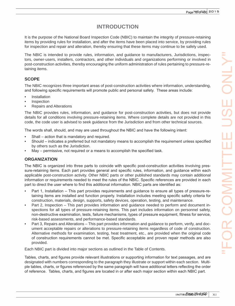
It is the purpose of the National Board Inspection Code (NBIC) to maintain the integrity of pressure-retaining items by providing rules for installation, and after the items have been placed into service, by providing rules for inspection and repair and alteration, thereby ensuring that these items may continue to be safely used.
The NBIC is intended to provide rules, information, and guidance to manufacturers, Jurisdictions, inspec-tors, owner-users, installers, contractors, and other individuals and organizations performing or involved in post-construction activities, thereby encouraging the uniform administration of rules pertaining to pressure-re-taining items.
SCOPEThe NBIC recognizes three important areas of post-construction activities where information, understanding, and following specific requirements will promote public and personal safety. These areas include:• Installation• Inspection• Repairs and Alterations The NBIC provides rules, information, and guidance for post-construction activities, but does not provide details for all conditions involving pressure-retaining items. Where complete details are not provided in this code, the code user is advised to seek guidance from the Jurisdiction and from other technical sources.
The words shall, should, and may are used throughout the NBIC and have the following intent:• Shall – action that is mandatory and required.• Should – indicates a preferred but not mandatory means to accomplish the requirement unless specified
by others such as the Jurisdiction.• May – permissive, not required or a means to accomplish the specified task.
ORGANIZATIONThe NBIC is organized into three parts to coincide with specific post-construction activities involving pres-sure-retaining items. Each part provides general and specific rules, information, and guidance within each applicable post-construction activity. Other NBIC parts or other published standards may contain additional information or requirements needed to meet the rules of the NBIC. Specific references are provided in each part to direct the user where to find this additional information. NBIC parts are identified as:• Part 1, Installation – This part provides requirements and guidance to ensure all types of pressure-re-
taining items are installed and function properly. Installation includes meeting specific safety criteria for construction, materials, design, supports, safety devices, operation, testing, and maintenance.
• Part 2, Inspection – This part provides information and guidance needed to perform and document in-spections for all types of pressure-retaining items. This part includes information on personnel safety, non-destructive examination, tests, failure mechanisms, types of pressure equipment, fitness for service, risk-based assessments, and performance-based standards.
• Part 3, Repairs and Alterations – This part provides information and guidance to perform, verify, and doc-ument acceptable repairs or alterations to pressure-retaining items regardless of code of construction. Alternative methods for examination, testing, heat treatment, etc., are provided when the original code of construction requirements cannot be met. Specific acceptable and proven repair methods are also provided.
Each NBIC part is divided into major sections as outlined in the Table of Contents.
Tables, charts, and figures provide relevant illustrations or supporting information for text passages, and are designated with numbers corresponding to the paragraph they illustrate or support within each section. Multi-ple tables, charts, or figures referenced by the same paragraph will have additional letters reflecting the order of reference. Tables, charts, and figures are located in or after each major section within each NBIC part.
"FO
RC
OM
MIT
TEE
US
EO
NLY
"
Page 18 of 400
Page 18 of 400
XII
NATIONAL BOARD INSPECTION CODE2015
INTRODUCTION
TEXT IDENTIFICATION AND NUMBERINGEach page in the text will be designated in the top header with the publication’s name, part number, and part title. The numbering sequence for each section begins with the section number followed by a dot to further designate major sections (e.g., 1.1, 1.2, 1.3). Major sections are further subdivided using dots to designate subsections within that major section (e.g., 1.1.1, 1.2.1, 1.3.1). Subsections can further be divided as neces-sary. Paragraphs under sections or subsections shall be designated with small letters in parenthesis (e.g., a), b), c)) and further subdivided using numbers in parenthesis (e.g., 1), 2), 3)).
Subdivisions of paragraphs beyond this point will be designated using a hierarchical sequence of letters and numbers followed by a dot.
Example: 2.1 Major Section 2.1.1 Section 2.1.2 Section 2.1.2. Subsection a) paragraph b) paragraph 1) subparagraph 2) subparagraph a. subdivisions 1. subdivisions 2. subdivisions b. subdivisions 1. subdivisions 2. subdivisions
Tables and figures will be designated with the referencing section or subsection identification. When more than one table or figure is referenced in the same section or subsection, letters or numbers in sequential order will be used following each section or subsection identification.
SUPPLEMENTSSupplements are contained in each part of the NBIC to provide rules, information, and guidance only pertain-ing to a specific type of pressure-retaining item (e.g., Locomotive Boilers, Historical Boilers, Graphite Pres-sure Vessels.) Supplements follow the same numbering system used for the main text only preceded by the Letter “S.” Each page of the supplement will be tabbed to identify the supplement number.
EDITIONSEditions, which include revisions and additions to this code, are published every two years. Editions are per-missive on the date issued and become mandatory six months after the date of issue.
INTERPRETATIONSOn request, the NBIC Committee will render an interpretation of any requirement of this code. Interpretations are provided for each part and are specific to the code edition and addenda referenced in the interpretation. Interpretations provide clarification of existing rules in the code only and are not part of this code.
JURISDICTIONAL PRECEDENCEReference is made throughout this code to the requirements of the “Jurisdiction.” Where any provision herein presents a direct or implied conflict with any jurisdictional regulation, the Jurisdictional regulation shall govern.
UNITS OF MEASUREMENTBoth U.S. customary units and metric units are used in the NBIC. The value stated in U.S. customary units or metric units are to be regarded separately as the standard. Within the text, the metric units are shown in
"FO
RC
OM
MIT
TEE
US
EO
NLY
"
Page 19 of 400
Page 19 of 400

XIII
2015
INTRODUCTION
NB-23
parentheses. In Part 2, Supplement 6 and Part 3, Supplement 6 regarding DOT Transport Tanks, the metric units are shown first with the U.S. customary units shown in parentheses.
U.S. customary units or metric units may be used with this edition of the NBIC, but one system of units shall be used consistently throughout a repair or alteration of pressure-retaining items. It is the responsibility of Na-tional Board accredited repair organizations to ensure the appropriate units are used consistently throughout all phases of work. This includes materials, design, procedures, testing, documentation, and stamping. The NBIC policy for metrication is outlined in each part of the NBIC.
ACCREDITATION PROGRAMSThe National Board administers and accredits three specific repair programs1 as shown below:
“R”……….Repairs and Alterations to Pressure-Retaining Items “VR”……..Repairs to Pressure Relief Valves “NR”……..Repair and Replacement Activities for Nuclear Items
Part 3, Repairs and Alterations, of the NBIC describes the administrative requirements for the accreditation of these repair organizations.
The National Board also administers and accredits four specific inspection agency programs as shown below:New Construction
Criteria for Acceptance of Authorized Inspection Agencies for New Construction (NB-360)Inservice Qualifications and Duties for Authorized Inspection Agencies (AIAs) Performing Inservice Inspection
Activities and Qualifications for Inspectors of Boilers and Pressure Vessels (NB-369)Owner-User
Accreditation of Owner-User Inspection Organizations (OUIO) (NB-371) Owners or users may be accredited for both a repair and inspection program provided the requirements for each accreditation program are met.
Federal Government Qualifications and Duties for Federal Inspection Agencies Performing Inservice Inspection Activities
(FIAs) (NB-390)These programs can be viewed on the National Board Website at www.nationalboard.org. For questions or further information regarding these programs contact the National Board by phone at (614) 888-8320 or by fax at (614) 847-1828
CERTIFICATES OF AUTHORIZATION FOR ACCREDITATION PROGRAMSAny organization seeking an accredited program may apply to the National Board to obtain a Certificate of Authorization for the requested scope of activities. A confidential review shall be conducted to evaluate the organization’s quality system. Upon completion of the evaluation, a recommendation will be made to the Na-tional Board regarding issuance of a Certificate of Authorization.
Certificate of Authorization scope, issuance, and revisions for National Board accreditation programs are specified in the applicable National Board procedures. When the quality system requirements of the appro-priate accreditation program have been met, a Certificate of Authorization and appropriate National Board symbol stamp shall be issued.
1 Caution, some Jurisdictions may independently administer a program of authorization for organizations to perform repairs and alterations within that Jurisdiction.
"FO
RC
OM
MIT
TEE
US
EO
NLY
"
Page 20 of 400
Page 20 of 400
XIV
NATIONAL BOARD INSPECTION CODE2015
FOREWORD
FOREWORD
The National Board of Boiler and Pressure Vessel Inspectors is an organization comprised of Chief Inspectors for the states, cities, and territories of the United States and provinces and territories of Canada. It is orga-nized for the purpose of promoting greater safety to life and property by securing concerted action and main-taining uniformity in post-construction activities of pressure-retaining items, thereby ensuring acceptance and interchangeability among Jurisdictional authorities responsible for the administration and enforcement of various codes and standards.
In keeping with the principles of promoting safety and maintaining uniformity, the National Board originally published the NBIC in 1946, establishing rules for inspection and repairs to boilers and pressure vessels. The National Board Inspection Code (NBIC) Committee is charged with the responsibility for maintaining and revising the NBIC. In the interest of public safety, the NBIC Committee decided, in 1995, to revise the scope of the NBIC to include rules for installation, inspection, and repair or alteration to boilers, pressure vessels, piping, and nonmetallic materials.
In 2007, the NBIC was restructured into three parts specifically identifying important post-construction activi-ties involving safety of pressure-retaining items. This restructuring provides for future expansion, transparen-cy, uniformity, and ultimately improving public safety.
The NBIC Committee’s function is to establish rules of safety governing post-construction activities for the installation, inspection, and repair and alteration of pressure-retaining items, and to interpret these rules when questions arise regarding their intent. In formulating the rules, the NBIC Committee considers the needs and concerns of individuals and organizations involved in the safety of pressure-retaining items. The objective of the rules is to afford reasonably certain protection of life and property, so as to give a reasonably long, safe period of usefulness. Advancements in design and material and the evidence of experience are recognized.
The rules established by the NBIC Committee are not to be interpreted as approving, recommending, or en-dorsing any proprietary or specific design, or as limiting in any way an organization’s freedom to choose any method that conforms to the NBIC rules.
The NBIC Committee meets regularly to consider revisions of existing rules, formulation of new rules, and respond to requests for interpretations. Requests for interpretation must be addressed to the NBIC Secretary in writing and must give full particulars in order to receive Committee consideration and a written reply. Pro-posed revisions to the code resulting from inquiries will be presented to the NBIC Committee for appropriate action.
Proposed revisions to the code approved by the NBIC Committee are submitted to the American National Standards Institute and published on the National Board web-site to invite comments from all interested per-sons. After the allotted time for public review and final approval, the new edition is published.
Organizations or users of pressure-retaining items are cautioned against making use of revisions that are less restrictive than former requirements without having assurance that they have been accepted by the Jurisdic-tion where the pressure-retaining item is installed.
The general philosophy underlying the NBIC is to parallel those provisions of the original code of construction, as they can be applied to post-construction activities.
The NBIC does not contain rules to cover all details of post-construction activities. Where complete details are not given, it is intended that individuals or organizations, subject to the acceptance of the Inspector and Jurisdiction when applicable, provide details for post-construction activities that will be as safe as otherwise provided by the rules in the original code of construction.
Activities not conforming to the rules of the original code of construction or the NBIC must receive specific approval from the Jurisdiction, who may establish requirements for design, construction, inspection, testing, and documentation.
"FO
RC
OM
MIT
TEE
US
EO
NLY
"
Page 21 of 400
Page 21 of 400

XV
NB-23 2015
FOREWORD
There are instances where the NBIC serves to warn against pitfalls; but the code is not a handbook, and cannot substitute for education, experience, and sound engineering judgment.
It is intended that this edition of the NBIC not be retroactive. Unless the Jurisdiction imposes the use of an earlier edition, the latest effective edition is the governing document.
"FO
RC
OM
MIT
TEE
US
EO
NLY
"
Page 22 of 400
Page 22 of 400
XVI
NATIONAL BOARD INSPECTION CODE2015
PERSONNEL
PERSONNEL The National Board of Boiler and Pressure Vessel Inspectors
Board of Trustees
J.H. Burpee Chairman
J.T. AmatoFirst Vice Chairman
M.A. Burns Second Vice Chairman
B. AnthonyMember at Large
C.B. Cantrell Member at Large
M. Washington Member at Large
K. Watson Member at Large
D.A. Douin Secretary/Treasurer
Advisory Committee
J. Pillow Representing welding industries
P.F. Martin Representing organized labor
K. Moore Representing National Board stamp holders
H.M. Richards Representing boiler and pressure vessel users
M.J. Pischke Representing pressure vessel manufacturers
R.V. WielgoszinskiRepresenting authorized inspection agencies(insurance companies)
P. Molvie Representing boiler manufacturers
"FO
RC
OM
MIT
TEE
US
EO
NLY
"
Page 23 of 400
Page 23 of 400
XVII
2015
PERSONNEL
NB-23
National Board MembersAlabama ...........................................................................................................................................................Ralph P. PateAlaska................................................................................................................................................................. Chris FultonArizona .......................................................................................................................................................Randall D. AustinArkansas................................................................................................................................................... Dennis R. HannonCalifornia ...................................................................................................................................................... Donald C. CookColorado........................................................................................................................................................... Steve NelsonDelaware ...............................................................................................................................................................John EschFlorida .........................................................................................................................................................Michael A. BurnsGeorgia....................................................................................................................................................Benjamin CrawfordHawaii............................................................................................................................................................ Julius Dacanay Illinois.............................................................................................................................................................. Clayton NovakIowa...................................................................................................................................................................Ulrich MerkleKansas....................................................................................................................................................... Charles Wilson IIIKentucky.........................................................................................................................................................Rodney HandyLouisiana .......................................................................................................................................................Joseph LeSageMaine.............................................................................................................................................................John H. BurpeeMaryland..............................................................................................................................................................Karl J. KraftMassachusetts........................................................................................................................................ Edward S. Kawa Jr.Michigan ............................................................................................................................................................. Mark MooreMinnesota......................................................................................................................................................... Joel T. AmatoMississippi ............................................................................................................................................... Kenneth L. WatsonMissouri .....................................................................................................................................................Ronald Brockman Nebraska ........................................................................................................................................... Christopher B. CantrellNevada ..............................................................................................................................................................Gary SchultzNew Hampshire .............................................................................................................................................. Darrell MalloryNew Jersey............................................................................................................................................... Milton WashingtonNew York ...................................................................................................................................................Matthew SansoneNorth Carolina ...................................................................................................................................................Cliff DautrichNorth Dakota .................................................................................................................................................... Trevor SeimeOhio...............................................................................................................................................................John E. SharierOklahoma .................................................................................................................................................. Terrence HellmanOregon ..............................................................................................................................................................Mark PerduePennsylvania ................................................................................................................................................ Nathaniel SmithRhode Island .............................................................................................................................................Benjamin AnthonySouth Carolina............................................................................................................................................Ronald W. SpikerSouth Dakota...................................................................................................................................................Aaron LorimorTexas .....................................................................................................................................................................Rob TrouttUtah..................................................................................................................................................................Rick K. SturmVirginia........................................................................................................................................................ Edward G. HiltonWashington............................................................................................................................................................. Tony OdaWest Virginia ................................................................................................................................................John F. PorcellaWisconsin ..............................................................................................................................................Michael J. Verhagen
Chicago, IL ...................................................................................................................................................Michael J. RyanDetroit, MI ....................................................................................................................................................Cortney JacksonLos Angeles, CA.............................................................................................................................................Cirilo S. ReyesMilwaukee, WI ...................................................................................................................................................... Jillian KlugNew York, NY ............................................................................................................................................William McGivneySeattle, WA............................................................................................................................................................ Larry Leet
Alberta ....................................................................................................................................................Michael PoehlmannBritish Columbia .............................................................................................................................................Anthony SchollManitoba...........................................................................................................................................................Derrick SlaterNew Brunswick............................................................................................................................................ Eben L. CreaserNewfoundland & Labrador.......................................................................................................................E. Dennis EastmanNorthwest Territories.................................................................................................................................. Matthias MailmanNova Scotia ....................................................................................................................................................... Peter Dodge Ontario........................................................................................................................................................... Michael AdamsPrince Edward Island................................................................................................................................. Steven TownsendQuebec......................................................................................................................................................... Madiha M. KotbSaskatchewan .......................................................................................................................................Christopher Selinger
"FO
RC
OM
MIT
TEE
US
EO
NLY
"
Page 24 of 400
Page 24 of 400

XVIII
NATIONAL BOARD INSPECTION CODE2015
PERSONNEL
National Board Inspection Code Main Committee
D. Cook, Chair State of California
R. Wielgoszinski, Vice ChairHartford Steam Boiler Inspection and Insurance Company of Connecticut
B. Besserman, Secretary National Board
B. AnthonyState of Rhode Island
P. BourgeoisTravelers
S. Cammeresi National Board Certificate Holders
D. CanonicoCanonico & Associates
P. Edwards CB&I, Inc.
G. Galanes Diamond Technical Services, Inc.
C. HopkinsSeattle Boiler Works, Inc.
L. McManoman Great Lakes Area Apprenticeship Program
M. Mooney Liberty Mutual Insurance Company
B. Morelock Eastman Chemical Company
V. Newton OneCIS Insurance Company
R. Pate State of Alabama
J. Pillow General Interest
R. Pulliam Manufacturers
M. Richards Users
J. Riley Users
B. Schulte Users
J. Sekely General Interest
K. Simmons National Board Certificate Holders
S. Staniszewski Jr.Regulatory Authorities
R. TroutJurisdictional Authorities
M. Webb Users
"FO
RC
OM
MIT
TEE
US
EO
NLY
"
Page 25 of 400
Page 25 of 400
XIX
2015
PERSONNEL
NB-23
National Board Inspection Code Subcommittee Installation (Part 1)
H. Richards, Chair Southern Company
D. Patten, Vice ChairR.F. MacDonald Co.
J. Bock, Secretary National Board
P. Bourgeois Travelers
G. Halley ABMA
S. Konopacki NRG
B. Moore Hartford Steam Boiler Inspection and Insurance Company of Connecticut
P. Schuelke Well-McLain
M. Wadkinson Fulton Boiler Works, Inc.
K. WatsonState of Mississippi
E. Wiggins Liberty Mutual Insurance Company
National Board Inspection Code Subcommittee Inspection (Part 2)
M. Mooney, Chair Liberty Mutual Insurance Company
S. Staniszewski, Vice Chair US Department of Transportation
J. Metzmaier, SecretaryNational Board
T. BarkerFM Global
D. Canonico Canonico & Associates
M. ClarkStructural Integrity Associates
J. Getter Worthington Cylinders
M. HorbaczewskiMidwest Generation
G. McRae Trinity Industries, Inc.
V. Newton OneCIS Insurance Company
R. Pate State of Alabama
J. Riley Phillips 66
J. Safarz CEC Combustion Services Group
M. Schwartzwalder AEP
T. Vandini Quality Steel Corporation
P. Welch Arise, Inc.
"FO
RC
OM
MIT
TEE
US
EO
NLY
"
Page 26 of 400
Page 26 of 400
XX
NATIONAL BOARD INSPECTION CODE2015
PERSONNEL
National Board Inspection Code Subcommittee for Repairs and Alterations (Part 3)
G. Galanes, Chair Diamond Technical Services, Inc.
J. Pillow, Vice Chair Common Arc Corporation
W. Vallance, Secretary National Board
J. AmatoState of Minnesota
B. BoseoGraycor Services LLC
A. BramucciAlstom Power
P. Edwards CB&I, Inc.
C. Hopkins Seattle Boiler Works, Inc.
W. Jones Arise, Inc.
J. Larson OneBeacon America Insurance Company
L. McManoman Great Lakes Area Apprenticeship Program
R. Miletti Babcock and Wilcox Construction Company, Inc.
K. MooreJoe Moore Company
B. Morelock Eastman Chemical Company
E. Ortman Alstom Power Inc.
B. Schulte NRG Texas, LP
J. Sekely Welding Services, Inc.
R. TrouttState of Texas
M. Webb Xcel Energy
National Board Inspection Code Subcommittee Pressure Relief Devices (Parts 1, 2, and 3)
S. Cammeresi, Chair CCR
A. Cox, Vice Chair Industrial Value
T. Beirne, Secretary National Board
B. AnthonyState of Rhode Island
K. Beise Dowco Valve Company, Inc.
M. Brodeur International Valve & Instr. Corp.
D. DeMichaelE.I. Dupont De Nemours & Co.
R. DobbinsZurich N.A.
R. Donalson Tyco Valves and Controls
R. McCaffrey Quality Valve
D. McHugh Allied Valve, Inc.
B. Nutter E.I. Dupont De Nemours & Co.
T. Patel Farris Engineering
A. Renaldo Praxair, Inc.
K. SimmonsCrane Energy
"FO
RC
OM
MIT
TEE
US
EO
NLY
"
Page 27 of 400
Page 27 of 400
XXI
2015
PERSONNEL
NB-23
National Board Inspection Code Subgroup Installation (Part 1)
M. Wadkinson, Chair Fulton Boiler Works, Inc.
D. Patten, Vice Chair R.F. MacDonald Co.
J. Bock, Secretary National Board
P. Bourgeois St. Paul Travelers
T. Creacy Zurich Services Corporation
G. Halley ABMA
C. Hopkins Seattle Boiler Works, Inc.
S. Konopacki Midwest Generation
J. Millette UAB
B. Moore Hartford Steam Boiler Inspection and Insurance Company of Connecticut
H. Richards Southern Company
P. Schuelke Well-McLain
M. Washington State of New Jersey
K. Watson State of Mississippi
E. Wiggins Liberty Mutual Insurance Company
National Board Inspection Code Subgroup Inspection (Part 2)
J. Getter, Chair Worthington Cylinders
M. Schwartzwalder, Vice Chair AEP Service Corporation
J. Metzmaier, Secretary National Board
T. Barker FM Global
E. Brantley XL Insurance America, Inc.
D. Canonico Canonico & Associates
M. Clark Structural Integrity Associates
R. Dobbins Zurich N.A.
D. Ford US Department of Transportation
D. Graf Air Products and Chemicals, Inc.
M. Horbaczewski Midwest Generation
G. McRae Trinity Industries, Inc.
M. Mooney Liberty Mutual Insurance
V. Newton One CIS
R. Pate State of Alabama
J. Riley Phillips 66
J. Safarz CEC Combustion Services Group
S. Staniszewski US Department of Transportation
T. Vandini Quality Steel Corporation
P. Welch Arise, Inc.
National Board Inspection Code Subgroup for Repairs and Alterations (Part 3)
A. Bramucci, Chair Alstom Power Inc.
B. Schulte, Vice Chair NRG Texas, LP
W. Vallance, Secretary National Board
J. AmatoState of Minnesota
B. BoseoGraycor Services LLC
R. CauthonAPComPower, Inc.
P. EdwardsCB&I, Inc.
G. Galanes Diamond Technical Services, Inc.
C. Hopkins Seattle Boiler Works, Inc.
"FO
RC
OM
MIT
TEE
US
EO
NLY
"
Page 28 of 400
Page 28 of 400
XXII
NATIONAL BOARD INSPECTION CODE2015
PERSONNEL
F. Johnson PBF Energy
W. Jones Arise, Inc.
J. Larson One Beacon America Insurance Company
D. Martinez FM Global
L. McManoman Great Lakes Area Apprenticeship Program
R. Miletti Babcock and Wilcox Construction Company, Inc.
K. MooreJoe Moore Company
B. MorelockEastman Chemical
E. Ortman Alstom Power Inc.
J. PillowCommon Arc Corporation
R. Pulliam The Babcock & Wilcox Company
B. Schaefer AEP
J. Sekely Welding Services, Inc.
W. Sperko Sperko Engineering Services
M. TothBoiler Supply Company, Inc.
R. TrouttState of Texas
R. Valdez ARB, Inc.
M. Webb Xcel Energy
T. WhiteNRG
Special Subgroups for Installation, Inspection, and Repairs and Alterations (Parts 1, 2, and 3)
S. Cammeresi, Chair CCR
A. Cox, Vice Chair Industrial Value
T. Beirne, Secretary National Board
B. AnthonyState of Rhode Island
K. Beise Dowco Valve Company, Inc.
M. Brodeur International Valve & Instr. Corp.
D. DeMichaelE.I. Dupont De Nemours & Co.
R. DobbinsZurich N.A.
R. Donalson Tyco Valves and Controls
R. McCaffrey Quality Valve
D. McHugh Allied Valve, Inc.
B. Nutter E.I. Dupont De Nemours & Co.
T. Patel Farris Engineering
A. Renaldo Praxair, Inc.
K. SimmonsCrane Energy
National Board Inspection Code Subgroup Graphite
E. Soltow, Chair SGL Carbon Group/SGL Technic
F. Brown, Secretary National Board
T. BonnCarbone of America
K. Cummins Louisville Graphite
M. Minick One CIS Insurance
D. Sholar Mersen USA
A. Stupica SGL Carbon Group/SGL Technic
A. Viet Mersen USA
"FO
RC
OM
MIT
TEE
US
EO
NLY
"
Page 29 of 400
Page 29 of 400

XXIII
2015
PERSONNEL
NB-23
National Board Inspection Code Subgroup Fiber-Reinforced Pressure Vessels
B. Shelley, Chair DuPont
F. Brown, Secretary National Board
J. Bustillos Bustillos and Consultants
T. CowleyDupont
R. CrawfordL&M Fiberglass
D. Eisberg Energy Recovery Inc.
M. GormanDigital Wave
D. Hodgkinson Consultant
D. Keeler The Dow Chemical Company
N. Newhouse Lincoln Composites
J. Richter Sentinel Consulting, LLC
N. Sirosh LightSail Energy
National Board Inspection Code Subgroup Locomotive Boilers
L. Moedinger, Chair Strasburg Railroad
M. Janssen, Vice Chair Vapor Locomotive Company
B. Ferrel, Secretary National Board
S. Butler Midwest Locomotive & Machine Works
D. Conrad Valley Railroad Co.
R. Franzen Steam Services of America
D. Griner Arizona Mechanical Engineering
S. Jackson D & SNG
S. Lee Union Pacific Railroad
D. McCormack Consultant
G. RayTennessee Valley Authority
R. ReetzState of North Dakota
G. Scerbo Federal Railroad Administration
R. Stone ABB/Combustion Engineering
R. YuillConsultant
National Board Inspection Code Subgroup Historical Boiler
J. Amato, ChairState of Minnesota
T. Dillion, Vice Chair Deltak
B. Ferrell, Secretary National Board
R. Bryce Heartland Software Solutions
J. Getter Worthington Industries
F. Johnson PCS Phosphate
J. Larson One Beacon America
C. Novak State of Illinois
D. Rupert Consultant
M. Wahl WHSEA
"FO
RC
OM
MIT
TEE
US
EO
NLY
"
Page 30 of 400
Page 30 of 400
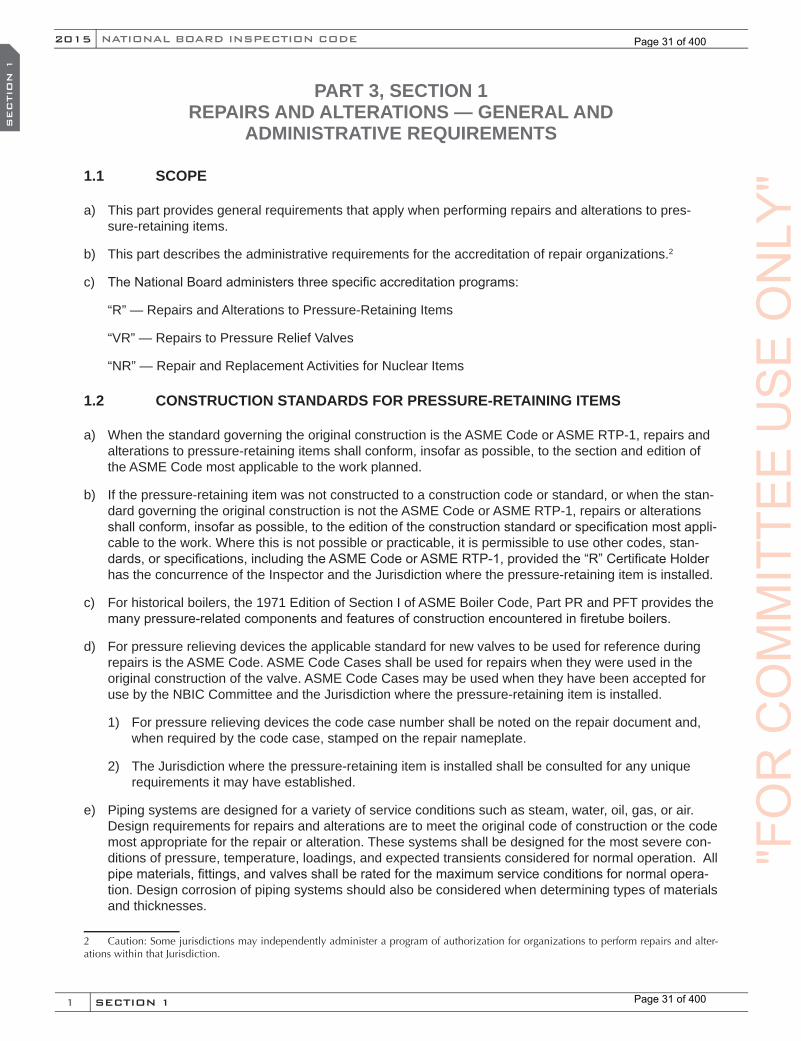
1
NATIONAL BOARD INSPECTION CODE2015
SECTION 1
SEC
TIO
N 1
PART 3, SECTION 1 REPAIRS AND ALTERATIONS — GENERAL AND
ADMINISTRATIVE REQUIREMENTS
1.1 SCOPE
a) This part provides general requirements that apply when performing repairs and alterations to pres-sure-retaining items.
b) This part describes the administrative requirements for the accreditation of repair organizations.2
c) The National Board administers three specific accreditation programs:
“R” — Repairs and Alterations to Pressure-Retaining Items
“VR” — Repairs to Pressure Relief Valves
“NR” — Repair and Replacement Activities for Nuclear Items
1.2 CONSTRUCTION STANDARDS FOR PRESSURE-RETAINING ITEMS
a) When the standard governing the original construction is the ASME Code or ASME RTP-1, repairs and alterations to pressure-retaining items shall conform, insofar as possible, to the section and edition of the ASME Code most applicable to the work planned.
b) If the pressure-retaining item was not constructed to a construction code or standard, or when the stan-dard governing the original construction is not the ASME Code or ASME RTP-1, repairs or alterations shall con form, insofar as possible, to the edition of the construction standard or specifica tion most appli-cable to the work. Where this is not possible or practicable, it is permissible to use other codes, stan-dards, or specifications, including the ASME Code or ASME RTP-1, provided the “R” Certificate Holder has the concurrence of the Inspector and the Jurisdiction where the pressure-retaining item is installed.
c) For historical boilers, the 1971 Edition of Section I of ASME Boiler Code, Part PR and PFT provides the many pressure-related components and features of construction encountered in firetube boilers.
d) For pressure relieving devices the applicable standard for new valves to be used for reference during repairs is the ASME Code. ASME Code Cases shall be used for repairs when they were used in the original construction of the valve. ASME Code Cases may be used when they have been accepted for use by the NBIC Committee and the Jurisdiction where the pressure-retaining item is installed.
1) For pressure relieving devices the code case number shall be noted on the repair document and, when required by the code case, stamped on the repair nameplate.
2) The Jurisdiction where the pressure-retaining item is installed shall be consulted for any unique requirements it may have established.
e) Piping systems are designed for a variety of service conditions such as steam, water, oil, gas, or air. Design requirements for repairs and alterations are to meet the original code of construction or the code most appropriate for the repair or alteration. These systems shall be designed for the most severe con-ditions of pressure, temperature, loadings, and expected transients considered for normal operation. All pipe materials, fittings, and valves shall be rated for the maximum service conditions for normal opera-tion. Design corrosion of piping systems should also be considered when determining types of materials and thicknesses.
2 Caution: Some jurisdictions may independently administer a program of authorization for organizations to perform repairs and alter-ations within that Jurisdiction.
"FO
RC
OM
MIT
TEE
US
EO
NLY
"
Page 31 of 400
Page 31 of 400
2
NB-23 2015
SECTION 1
SEC
TIO
N 1
f) For Transport Tanks, the Competent Authority (DOT) shall be consulted for any requirements which it has established since they take precedence for repairs.
1) Transport tanks manufactured prior to the adoption of ASME Section XII by the Competent Authority(DOT) were constructed in accordance with ASME Section VIII, Division 1. Certain transport tanks manufactured to this code were required to be stamped in accordance with Section VIII, Division 1, if the design pressure of the transport tank was 241 kPa (35 psi) (depending on material being transported) and greater. If the design pressure was less than 241 kPa (35 psi) (depending on material being transported), the transport tank was manufactured in accordance with Section VIII, Division 1, but not required by the Competent Authority (DOT) to be stamped.
2) ASME stamped transport tanks are subject to the requirements of NBIC Part 3, for continued inser-vice repairs, alterations, or modifications, unless exempted by the Competent Authority (DOT).
1.3 INSPECTOR
a) Inspection and certification shall be made by an Inspector holding the appropriate commission issued by the National Board and employed by an Authorized Inspection Agency (see NBIC Part 3, Section 9, Glossary of Terms, for definition of Authorized Inspection Agency).
b) An Inspector employed by an Owner-User Inspection Organization or a Federal Inspection Agency may authorize and accept work only on pressure-retaining items owned or used by the respective organiza-tion. Each accredited Owner-User Inspection Organization’s quality program shall have specific approv-al of the Jurisdiction as required.
1.3.1 AUTHORIZATION
a) The Inspector’s authorization to perform a repair or alteration shall be obtained by the repair organiza-tion prior to initiation of a repair or alteration to a pressure-retaining item. The Inspector shall determine that the repair or alteration methods are acceptable.
b) Subject to acceptance of the Jurisdiction, the Inspector may give approval for routine repairs prior to the start of work provided the Inspector ensures that the “R” Certificate Holder has adequately addressed routine repairs in the quality program.
1.3.2 ACCEPTANCE INSPECTION
a) The Inspector making the acceptance inspection shall be the same Inspector who authorized the repair or alteration. Where this is not possible or practicable, another Inspector may perform the acceptance inspection; however, in all cases, the Inspector who performs the acceptance inspection shall be an employee of the same organization as the Inspector who authorized the repair or alteration.
b) Before signing the appropriate NBIC Report Form, the Inspector shall review the drawings, ensure the repair or alteration was performed in accordance with the accepted code of construction or standard, witness any pressure test or any acceptable alternative test method applied, ensure that the required nondestructive examinations have been performed satisfactorily, and that the other functions necessary to ensure compliance with the requirements of this code have been satisfactorily performed.
c) The Inspector shall verify the stamping or nameplate is correct and where applicable, the nameplate has been properly attached.
1.4 DEFINITIONS RELATING TO PRESSURE RELIEF DEVICES
Unless otherwise specified in these rules and procedures, the definitions relating to pressure relief devices in Section 2 of ANSI/ASME PTC-25 shall apply.
(15)
"FO
RC
OM
MIT
TEE
US
EO
NLY
"
Page 32 of 400
Page 32 of 400
3
NATIONAL BOARD INSPECTION CODE2015
SECTION 1
SEC
TIO
N 1
1.5 ACCREDITATION
a) Organizations performing repairs or alterations to pressure-retaining items shall be accredited as de-scribed in this section, as appropriate for the scope of work to be performed.
b) Organizations performing repairs outside the scope of the NBIC may be accredited and shall meet any additional requirements of the Jurisdiction where the work is performed.
1.5.1 ACCREDITATION PROCESS
a) The National Board administers accreditation programs for authorization of organizations performing repairs and alterations to pressure-retaining items and/or pressure relief valves.
b) Any organization may apply to the National Board to obtain a Certificate of Authorization for the re-quested scope of activities. A review shall be conducted to evaluate the organization’s quality system. The individual assigned to conduct the evaluation shall meet the qualification requirements prescribed by the National Board. Upon completion of the evaluation, any deficiencies within the organization’s quality system will be documented and a recommendation will be made to the National Board regarding issuance of a Certificate of Authorization.
c) As part of the accreditation process, an applicant’s quality system is subject to a review. National Board procedures provide for the confidential review resulting in recommendations to issue or not issue a Certificate of Authorization.
d) The accreditation programs provide requirements for organizations performing repairs and alterations to pressure-retaining items. Depending upon the expected scope of activities at the time of review, orga-nizations may be authorized to perform design only, metallic or non-metallic repairs, and/or alterations either in the shop only, field only, or shop and field. Repairs and/or alterations to metallic and non-metal-lic pressure-retaining items are made by welding, bonding and/or mechanical assembly.
e) Organizations desiring to renew or obtain a National Board Certificate of Authorization shall apply to the National Board using forms obtained from the National Board. Application for renewal shall be made prior to the expiration date of the Certificate of Authorization.
f) When an organization has plants or shops in more than one location, the organization shall submit separate applications for each plant or shop. The organization may perform repairs or alterations in its plants, shops, or in the field, provided such operations are described in the organization’s Quality System.
g) The Jurisdiction3 may audit the Quality System and activities of an organization upon a valid request from an owner, user, inspection agency, or the National Board.
h) The NBIC Committee may at any time change the rules for the issuance of Certificates of Authorizationand use of the “R” Symbol Stamp. These rules shall become binding on all certificate holders.
1.5.2 NATIONAL BOARD “R” SYMBOL STAMP
a) All “R” Symbol Stamps shall be obtained from The National Board of Boiler and Pressure Vessel Inspectors. Authorization to use the “R” Symbol Stamp may be granted by the National Board at its absolute discretion to the certificate holder.
b) The “R” Symbol Stamp is furnished on loan by the National Board for a nominal fee. Each organization
3 Jurisdiction: The National Board member Jurisdiction where the organization is located. Alternatively, where the Jurisdiction elects not to perform the review or where there is no Jurisdiction or where the Jurisdiction is the organization’s Authorized Inspection Agency, The National Board of Boiler and Pressure Vessel Inspectors will represent the Jurisdiction. At the Jurisdiction’s discretion, the Jurisdiction may choose to be a member of the review team if the Jurisdiction chooses not to be the team leader.
"FO
RC
OM
MIT
TEE
US
EO
NLY
"
Page 33 of 400
Page 33 of 400

4
NB-23 2015
SECTION 1
SEC
TIO
N 1
shall agree if authorization to use the “R” Symbol Stamp is granted, that the “R” Symbol Stamp is at all times the property of the National Board and will be promptly returned upon demand. If the organiza-tion discontinues the use of the “R” Symbol Stamp, inspection agreement with an Authorized Inspection Agency, or if the Certificate of Authorization has expired and no new certificate has been issued, the “R” Symbol Stamp shall be returned to the National Board.
c) The organization’s Quality System shall provide for adequate control of the “R” Symbol Stamp. Provi-sions may be made for the issuance of the “R” Symbol Stamp for use at various field locations.
d) The holder of a Certificate of Authorization may obtain more than one “R” Symbol Stamp provided theorganization’s Quality System describes how the use of such stamps is controlled from the location shown on the certificate.
e) An organization shall not permit others to use the “R” Symbol Stamp loaned to it by the National Board.
1.6 QUALITY SYSTEM
A holder of a National Board Certificate of Authorization shall have and maintain a written Quality System. The System shall satisfactorily meet the requirements of the NBIC and shall be available for review. The Quality System may be brief or voluminous, depending on the projected scope of work. It shall be treated confiden-tially by the National Board.
1.6.1 OUTLINE OF REQUIREMENTS FOR A QUALITY SYSTEM FOR QUALIFICATION FOR THE NATIONAL BOARD “R” CERTIFICATE OF AUTHORIZATION
The following is a guide for required features of a Quality System which shall be included in the organization’s Quality System Manual. As a minimum, each organization shall address the required features relative to the scope of work to be performed. Organizations shall explain their intent, capability and applicability for each required feature outlined in this section. Work may be subcontracted provided controls are clearly defined for maintaining full responsibility for code compliance by the National Board repair organization certifying the work.
a) Title Page
The name and complete address of the company to which the National Board Certificate of Authorization is issued shall be included on the title page of the Quality System Manual.
b) Contents Page
The manual should contain a page listing the contents of the manual by subject, number (if applicable), and revision number of each document.
c) Scope of Work
The manual shall clearly indicate the scope and type of repairs or alterations the organization is capable of and intends to carry out.
d) Statement of Authority and Responsibility
A dated Statement of Authority, signed by an officer of the organization, shall be included in the manual. Further, the Statement of Authority shall include:
1) A statement that all repairs or alterations carried out by the organization shall meet the require-ments of the NBIC and the Jurisdiction, as applicable;
2) A statement that if there is a disagreement in the implementation of the Quality System, the matter is to be referred for resolution to a higher authority in the company;
"FO
RC
OM
MIT
TEE
US
EO
NLY
"
Page 34 of 400
Page 34 of 400

5
NATIONAL BOARD INSPECTION CODE2015
SECTION 1
SEC
TIO
N 1
3) The title of the individual who will be responsible to ensure that 1) above is followed and has the freedom and authority to carry out the responsibility.
e) Manual Control
The manual shall include the necessary provisions for revising and issuing documents to keep the man-ual current. The title of the individual authorized to approve revisions shall be included in the manual. Revisions must be accepted by the Authorized Inspection Agency prior to issuance of the manual and its implementation.
f) Organization
An organizational chart shall be included in the manual. It shall include the title of the heads of all depart-ments or divisions that perform functions that can affect the quality of the repair or alteration, and it shall show the relationship between each department or division.
The manual shall identify the title of those individuals responsible for preparation, implementation, or ver-ification of the Quality System. The responsibilities shall be clearly defined and the individuals shall have the organizational freedom and authority to fulfill those responsibilities.
g) Drawings, Design and Specifications
The manual shall contain controls to ensure that all design information, applicable drawings, design cal-culations, specifications, and instructions are prepared or obtained, controlled, and interpreted in accor-dance with the original code of construction.
h) Repair and Alteration Methods
The manual shall include controls for repairs and alterations, including mechanical assembly procedures, materials, nondestructive examination methods, pre-heat, and postweld heat treatment, as applicable. Special requirements such as nonmetallic repairs and alterations to graphite and fiber-reinforced thermo-setting plastic pressure-retaining items including bonding or mechanical assembly procedures shall be addressed, if applicable.
i) Materials
The manual shall describe the method used to ensure that only acceptable materials (including welding material) are used for repairs and alterations. The manual shall include a description of how existing material is identified and new material is ordered, verified, and identified. The manual shall identify the title of the individual(s) responsible for each function and a brief description of how the function is to be performed.
j) Method of Performing Work
The manual shall describe the methods for performing and documenting repairs and alterations in suffi-cient detail to permit the Inspector to determine at what stages specific inspections are to be performed. The method of repair or alteration must have prior acceptance of the Inspector.
k) Welding, NDE and Heat Treatment
The manual shall describe controls for welding, nondestructive examination, and heat treatment. The manual is to indicate the title of the individual(s) responsible for the welding procedure specification (WPS) and its qualification, and the qualification of welders and welding operators. It is essential that only welding procedure specifications and welders or welding operators qualified, as required by the NBIC, be used in the repair or alteration of pressure-retaining items. It is also essential that welders and welding operators maintain their proficiency as required by the NBIC, while engaged in the repair or alteration of pressure-retaining items. The manual shall also describe controls for ensuring that the required WPS or Standard Welding Procedure Specification (SWPS) is available to the welder or welding operator prior to
"FO
RC
OM
MIT
TEE
US
EO
NLY
"
Page 35 of 400
Page 35 of 400

6
NB-23 2015
SECTION 1
SEC
TIO
N 1
welding. Similar responsibility for nondestructive examination and heat treatment shall be described in the manual.
l) Examinations and Tests
Reference shall be made in the manual for examinations and tests upon completion of the repair or alteration.
m) Calibration
The manual shall describe a system for the calibration of examination, measuring, and test equipment used in the performance of repairs and alterations.
n) Acceptance and Inspection of Repair or Alteration
The manual shall specifically indicate that before the work is started, acceptance of the repair/alteration shall be obtained from an Inspector who will make the required inspections and confirm NBIC complianceby signing and dating the applicable NBIC Report Form 4 upon completion of the work.
o) Inspections
The manual shall make provisions for the Inspector to have access to all drawings, design calculations, specifications, procedures, process sheets, repair or alteration procedures, test results, and other docu-ments as necessary to ensure compliance with the NBIC. A copy of the current manual shall be available to the inspector.
p) Report of Repair or Alteration Form
The manual shall indicate the title of the individuals responsible for preparing, signing, and presenting the NBIC Report Forms to the Inspector. The distribution of the NBIC Report Forms4 shall be described in the manual.
q) Exhibits
Any forms referenced in the manual shall be included. The form may be a part of the referencing docu-ment or included as an appendix. For clarity, the forms may be completed and identified as examples. The name and accepted abbreviations of the “R” Certificate Holder shall be included in the manual.
r) Construction Code
The manual shall include provisions for addressing the requirements that pertain to the specific construc-tion code for the equipment being repaired or altered.
s) Nonconforming Items
There shall be a system acceptable to the Inspector for the correction of nonconformities. A nonconfor-mance is any condition that does not comply with the applicable rules of the NBIC, construction code, ju-risdictional requirements, or the quality system. Nonconformance must be corrected or eliminated before the repaired or altered component can be considered in compliance with the NBIC.
t) Records Retention
The quality manual shall describe a system for filing, maintaining, and easily retrieving records support-ing or substantiating the administration of the Quality System within the scope of the “R” Certificate of Authorization.
4 NBIC Report Form: National Board Form R-1 for Repair, Form R-2 for Alterations, Form R-3 for Fabricated Parts, or Form R-4 Report Supplementary Sheet.
"FO
RC
OM
MIT
TEE
US
EO
NLY
"
Page 36 of 400
Page 36 of 400
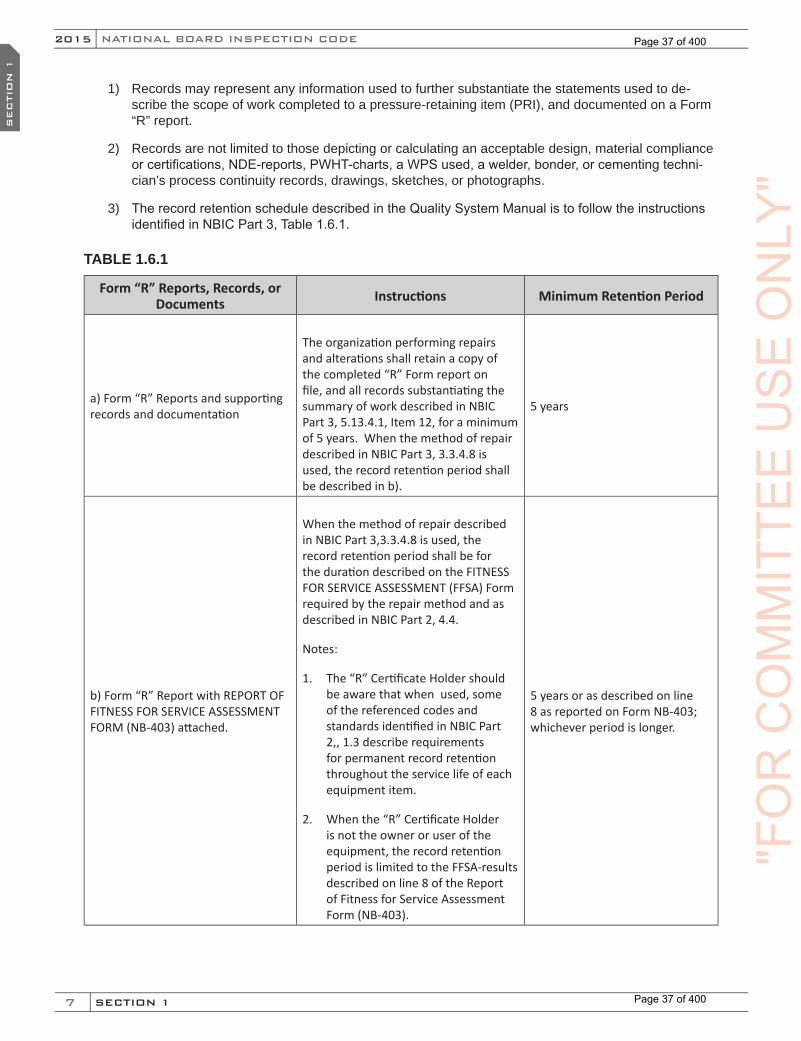
7
NATIONAL BOARD INSPECTION CODE2015
SECTION 1
SEC
TIO
N 1
1) Records may represent any information used to further substantiate the statements used to de-scribe the scope of work completed to a pressure-retaining item (PRI), and documented on a Form “R” report.
2) Records are not limited to those depicting or calculating an acceptable design, material compliance or certifications, NDE-reports, PWHT-charts, a WPS used, a welder, bonder, or cementing techni-cian’s process continuity records, drawings, sketches, or photographs.
3) The record retention schedule described in the Quality System Manual is to follow the instructions identified in NBIC Part 3, Table 1.6.1.
TABLE 1.6.1
Form “R” Reports, Records, or Documents Instructions Minimum Retention Period
a) Form “R” Reports and supporting records and documentation
The organization performing repairs and alterations shall retain a copy of the completed “R” Form report on file, and all records substantiating the summary of work described in NBIC Part 3, 5.13.4.1, Item 12, for a minimum of 5 years. When the method of repair described in NBIC Part 3, 3.3.4.8 is used, the record retention period shall be described in b).
5 years
b) Form “R” Report with REPORT OF FITNESS FOR SERVICE ASSESSMENT FORM (NB-403) attached.
When the method of repair described in NBIC Part 3,3.3.4.8 is used, the record retention period shall be for the duration described on the FITNESS FOR SERVICE ASSESSMENT (FFSA) Form required by the repair method and as described in NBIC Part 2, 4.4.
Notes:
1. The “R” Certificate Holder should be aware that when used, some of the referenced codes and standards identified in NBIC Part 2,, 1.3 describe requirements for permanent record retention throughout the service life of each equipment item.
2. When the “R” Certificate Holder is not the owner or user of the equipment, the record retention period is limited to the FFSA-results described on line 8 of the Report of Fitness for Service Assessment Form (NB-403).
5 years or as described on line 8 as reported on Form NB-403; whichever period is longer.
"FO
RC
OM
MIT
TEE
US
EO
NLY
"
Page 37 of 400
Page 37 of 400
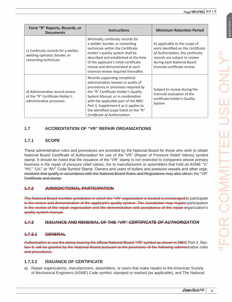
8
NB-23 2015
SECTION 1
SEC
TIO
N 1
Form “R” Reports, Records, or Documents Instructions Minimum Retention Period
c) Continuity records for a welder, welding operator, bonder, or cementing technician.
Minimally, continuity records for a welder, bonder, or cementing technician within the Certificate Holder’s quality system shall be described and established at the time of the applicant’s initial certificate review and demonstrated at each triennial review required thereafter.
As applicable to the scope of work identified on the Certificate of Authorization, the continuity records are subject to review during each National Board triennial certificate review.
d) Administrative record review of the “R” Certificate Holder’s administrative processes.
Records supporting completed administrative reviews or audits of procedures or processes required by the “R” Certificate Holder’s Quality System Manual, or in combination with the applicable part of the NBIC Part 3, Supplement 6 as it applies to the identified scope listed on the “R” Certificate of Authorization.
Subject to review during the triennial evaluation of the certificate holder’s Quality System.
1.7 ACCREDITATION OF “VR” REPAIR ORGANIZATIONS
1.7.1 SCOPE
These administrative rules and procedures are provided by the National Board for those who wish to obtain National Board Certificate of Authorization for use of the “VR” (Repair of Pressure Relief Valves) symbol stamp. It should be noted that the issuance of the “VR” stamp is not restricted to companies whose primary business is the repair of pressure relief valves, nor to manufacturers or assemblers that hold an ASME “V,” “HV,” “UV,” or “NV” Code Symbol Stamp. Owners and users of boilers and pressure vessels and other orga-nizations that qualify in accordance with the National Board Rules and Regulations may also obtain the “VR” Certificate and stamp.
1.7.2 JURISDICTIONAL PARTICIPATION
The National Board member jurisdiction in which the “VR” organization is located is encouraged to participate in the review and demonstration of the applicant’s quality system. The Jurisdiction may require participation in the review of the repair organization and the demonstration and acceptance of the repair organization’s quality system manual.
1.7.3 ISSUANCE AND RENEWAL OF THE “VR” CERTIFICATE OF AUTHORIZATION
1.7.3.1 GENERAL
Authorization to use the stamp bearing the official National Board “VR” symbol as shown in NBIC Part 3, Sec-tion 5, will be granted by the National Board pursuant to the provisions of the following administrative rules and procedures.
1.7.3.2 ISSUANCE OF CERTIFICATEa) Repair organizations, manufacturers, assemblers, or users that make repairs to the American Society
of Mechanical Engineers (ASME) Code symbol, stamped or marked (as applicable), and The National
"FO
RC
OM
MIT
TEE
US
EO
NLY
"
Page 38 of 400
Page 38 of 400
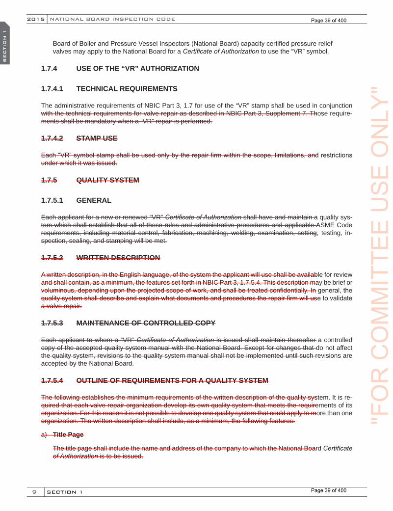
9
NATIONAL BOARD INSPECTION CODE2015
SECTION 1
SEC
TIO
N 1
Board of Boiler and Pressure Vessel Inspectors (National Board) capacity certified pressure relief valves may apply to the National Board for a Certificate of Authorization to use the “VR” symbol.
1.7.4 USE OF THE “VR” AUTHORIZATION
1.7.4.1 TECHNICAL REQUIREMENTS
The administrative requirements of NBIC Part 3, 1.7 for use of the “VR” stamp shall be used in conjunction with the technical requirements for valve repair as described in NBIC Part 3, Supplement 7. Those require-ments shall be mandatory when a “VR” repair is performed.
1.7.4.2 STAMP USE
Each “VR” symbol stamp shall be used only by the repair firm within the scope, limitations, and restrictions under which it was issued.
1.7.5 QUALITY SYSTEM
1.7.5.1 GENERAL
Each applicant for a new or renewed “VR” Certificate of Authorization shall have and maintain a quality sys-tem which shall establish that all of these rules and administrative procedures and applicable ASME Code requirements, including material control, fabrication, machining, welding, examination, setting, testing, in-spection, sealing, and stamping will be met.
1.7.5.2 WRITTEN DESCRIPTION
A written description, in the English language, of the system the applicant will use shall be available for review and shall contain, as a minimum, the features set forth in NBIC Part 3, 1.7.5.4. This description may be brief or voluminous, depending upon the projected scope of work, and shall be treated confidentially. In general, the quality system shall describe and explain what documents and procedures the repair firm will use to validate a valve repair.
1.7.5.3 MAINTENANCE OF CONTROLLED COPY
Each applicant to whom a “VR” Certificate of Authorization is issued shall maintain thereafter a controlled copy of the accepted quality system manual with the National Board. Except for changes that do not affect the quality system, revisions to the quality system manual shall not be implemented until such revisions are accepted by the National Board.
1.7.5.4 OUTLINE OF REQUIREMENTS FOR A QUALITY SYSTEM
The following establishes the minimum requirements of the written description of the quality system. It is re-quired that each valve repair organization develop its own quality system that meets the requirements of its organization. For this reason it is not possible to develop one quality system that could apply to more than one organization. The written description shall include, as a minimum, the following features:
a) Title Page
The title page shall include the name and address of the company to which the National Board Certificate of Authorization is to be issued.
"FO
RC
OM
MIT
TEE
US
EO
NLY
"
Page 39 of 400
Page 39 of 400
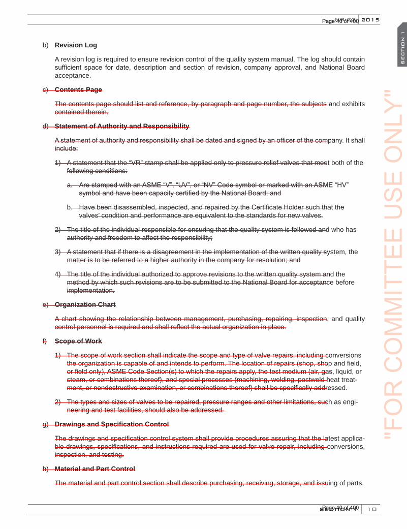
10
NB-23 2015
SECTION 1
SEC
TIO
N 1
b) Revision Log
A revision log is required to ensure revision control of the quality system manual. The log should contain sufficient space for date, description and section of revision, company approval, and National Board acceptance.
c) Contents Page
The contents page should list and reference, by paragraph and page number, the subjects and exhibits contained therein.
d) Statement of Authority and Responsibility
A statement of authority and responsibility shall be dated and signed by an officer of the company. It shall include:
1) A statement that the “VR” stamp shall be applied only to pressure relief valves that meet both of the following conditions:
a. Are stamped with an ASME “V”, “UV”, or “NV” Code symbol or marked with an ASME “HV” symbol and have been capacity certified by the National Board; and
b. Have been disassembled, inspected, and repaired by the Certificate Holder such that the valves’ condition and performance are equivalent to the standards for new valves.
2) The title of the individual responsible for ensuring that the quality system is followed and who has authority and freedom to affect the responsibility;
3) A statement that if there is a disagreement in the implementation of the written quality system, the matter is to be referred to a higher authority in the company for resolution; and
4) The title of the individual authorized to approve revisions to the written quality system and the method by which such revisions are to be submitted to the National Board for acceptance before implementation.
e) Organization Chart
A chart showing the relationship between management, purchasing, repairing, inspection, and quality control personnel is required and shall reflect the actual organization in place.
f) Scope of Work
1) The scope of work section shall indicate the scope and type of valve repairs, including conversions the organization is capable of and intends to perform. The location of repairs (shop, shop and field, or field only), ASME Code Section(s) to which the repairs apply, the test medium (air, gas, liquid, or steam, or combinations thereof), and special processes (machining, welding, postweld heat treat-ment, or nondestructive examination, or combinations thereof) shall be specifically addressed.
2) The types and sizes of valves to be repaired, pressure ranges and other limitations, such as engi-neering and test facilities, should also be addressed.
g) Drawings and Specification Control
The drawings and specification control system shall provide procedures assuring that the latest applica-ble drawings, specifications, and instructions required are used for valve repair, including conversions, inspection, and testing.
h) Material and Part Control
The material and part control section shall describe purchasing, receiving, storage, and issuing of parts.
"FO
RC
OM
MIT
TEE
US
EO
NLY
"
Page 40 of 400
Page 40 of 400
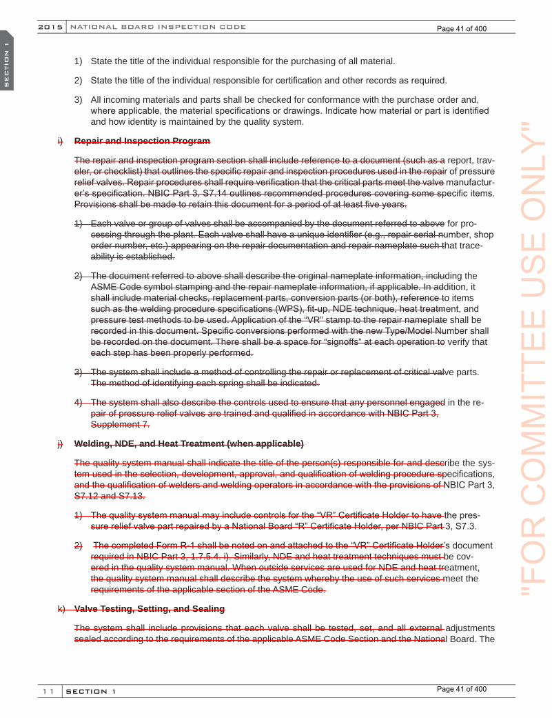
11
NATIONAL BOARD INSPECTION CODE2015
SECTION 1
SEC
TIO
N 1
1) State the title of the individual responsible for the purchasing of all material.
2) State the title of the individual responsible for certification and other records as required.
3) All incoming materials and parts shall be checked for conformance with the purchase order and, where applicable, the material specifications or drawings. Indicate how material or part is identified and how identity is maintained by the quality system.
i) Repair and Inspection Program
The repair and inspection program section shall include reference to a document (such as a report, trav-eler, or checklist) that outlines the specific repair and inspection procedures used in the repair of pressure relief valves. Repair procedures shall require verification that the critical parts meet the valve manufactur-er’s specification. NBIC Part 3, S7.14 outlines recommended procedures covering some specific items. Provisions shall be made to retain this document for a period of at least five years.
1) Each valve or group of valves shall be accompanied by the document referred to above for pro-cessing through the plant. Each valve shall have a unique identifier (e.g., repair serial number, shop order number, etc.) appearing on the repair documentation and repair nameplate such that trace-ability is established.
2) The document referred to above shall describe the original nameplate information, including the ASME Code symbol stamping and the repair nameplate information, if applicable. In addition, it shall include material checks, replacement parts, conversion parts (or both), reference to items such as the welding procedure specifications (WPS), fit-up, NDE technique, heat treatment, and pressure test methods to be used. Application of the “VR” stamp to the repair nameplate shall be recorded in this document. Specific conversions performed with the new Type/Model Number shall be recorded on the document. There shall be a space for “signoffs” at each operation to verify that each step has been properly performed.
3) The system shall include a method of controlling the repair or replacement of critical valve parts. The method of identifying each spring shall be indicated.
4) The system shall also describe the controls used to ensure that any personnel engaged in the re-pair of pressure relief valves are trained and qualified in accordance with NBIC Part 3, Supplement 7.
j) Welding, NDE, and Heat Treatment (when applicable)
The quality system manual shall indicate the title of the person(s) responsible for and describe the sys-tem used in the selection, development, approval, and qualification of welding procedure specifications, and the qualification of welders and welding operators in accordance with the provisions of NBIC Part 3, S7.12 and S7.13.
1) The quality system manual may include controls for the “VR” Certificate Holder to have the pres-sure relief valve part repaired by a National Board “R” Certificate Holder, per NBIC Part 3, S7.3.
2) The completed Form R-1 shall be noted on and attached to the “VR” Certificate Holder’s document required in NBIC Part 3, 1.7.5.4. i). Similarly, NDE and heat treatment techniques must be cov-ered in the quality system manual. When outside services are used for NDE and heat treatment, the quality system manual shall describe the system whereby the use of such services meet the requirements of the applicable section of the ASME Code.
k) Valve Testing, Setting, and Sealing
The system shall include provisions that each valve shall be tested, set, and all external adjustments sealed according to the requirements of the applicable ASME Code Section and the National Board. The
"FO
RC
OM
MIT
TEE
US
EO
NLY
"
Page 41 of 400
Page 41 of 400
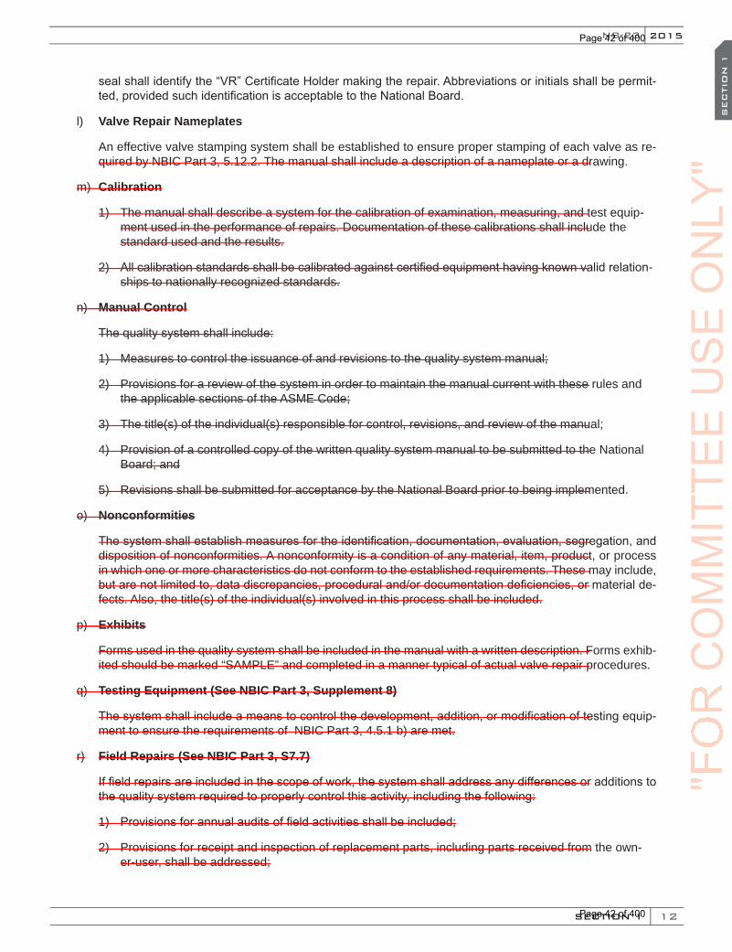
12
NB-23 2015
SECTION 1
SEC
TIO
N 1
seal shall identify the “VR” Certificate Holder making the repair. Abbreviations or initials shall be permit-ted, provided such identification is acceptable to the National Board.
l) Valve Repair Nameplates
An effective valve stamping system shall be established to ensure proper stamping of each valve as re-quired by NBIC Part 3, 5.12.2. The manual shall include a description of a nameplate or a drawing.
m) Calibration
1) The manual shall describe a system for the calibration of examination, measuring, and test equip-ment used in the performance of repairs. Documentation of these calibrations shall include the standard used and the results.
2) All calibration standards shall be calibrated against certified equipment having known valid relation-ships to nationally recognized standards.
n) Manual Control
The quality system shall include:
1) Measures to control the issuance of and revisions to the quality system manual;
2) Provisions for a review of the system in order to maintain the manual current with these rules and the applicable sections of the ASME Code;
3) The title(s) of the individual(s) responsible for control, revisions, and review of the manual;
4) Provision of a controlled copy of the written quality system manual to be submitted to the National Board; and
5) Revisions shall be submitted for acceptance by the National Board prior to being implemented.
o) Nonconformities
The system shall establish measures for the identification, documentation, evaluation, segregation, and disposition of nonconformities. A nonconformity is a condition of any material, item, product, or process in which one or more characteristics do not conform to the established requirements. These may include, but are not limited to, data discrepancies, procedural and/or documentation deficiencies, or material de-fects. Also, the title(s) of the individual(s) involved in this process shall be included.
p) Exhibits
Forms used in the quality system shall be included in the manual with a written description. Forms exhib-ited should be marked “SAMPLE” and completed in a manner typical of actual valve repair procedures.
q) Testing Equipment (See NBIC Part 3, Supplement 8)
The system shall include a means to control the development, addition, or modification of testing equip-ment to ensure the requirements of NBIC Part 3, 4.5.1 b) are met.
r) Field Repairs (See NBIC Part 3, S7.7)
If field repairs are included in the scope of work, the system shall address any differences or additions to the quality system required to properly control this activity, including the following:
1) Provisions for annual audits of field activities shall be included;
2) Provisions for receipt and inspection of replacement parts, including parts received from the own-er-user, shall be addressed;
"FO
RC
OM
MIT
TEE
US
EO
NLY
"
Page 42 of 400
Page 42 of 400

13
NATIONAL BOARD INSPECTION CODE2015
SECTION 1
SEC
TIO
N 1
3) If owner-user personnel will assist with repairs, provisions for the use of owner-user personnel shall be included; and
4) Provisions for use of owner-user measurement and test equipment, if applicable, shall be addressed.
1.8 “NR” PROGRAM REQUIREMENTS
1.8.1 SCOPE
a) This section provides requirements that must be met for an organization to obtain a National Board Cer-tificate of Authorization to use the “NR” Symbol Stamp for repair/replacement activities to nuclear items constructed in accordance with the requirements of the ASME Code or other internationally recognized codes or standards for construction or inservice inspection of nuclear facilities.
b) For administrative requirements to obtain or renew a National Board “NR” Certificate of Authorizationand the “NR” Symbol Stamp, refer to National Board Procedure NB-4175, Accreditation of “NR” Repair Organizations.
1.8.2 GENERAL
a) An organization applying for an “NR” Certificate of Authorization shall have a written Quality Assurance Program (QAP) that details the specific requirements to be met based on the intended category of activities selected by that organization as described below and shown in Table 1.8.2. Controls used, including electronic capabilities, in the Quality Assurance Program shall be documented in a Quality As-surance Manual (QAM). Controls required to be included within the QAM shall include who, what, when, where, why and how with an understanding that the how can be a reference to an implementation procedure or instruction. Quality activities to be described in the Quality Assurance Program is identified in Section 1.8.5 of this part. Applicants shall address all requirements in their Quality Assurance Pro-gram based on the category of activity and scope of work to be performed (organization’s capabilities) to which certification is requested.
b) Category 1
Any ASME Code certified item or system requiring repair/replacement activities irrespective of physical location and installation status prior to fuel loading.
c) Category 2
After fuel loading, any item or system under the scope of ASME Section XI requiring repair/replacementactivities irrespective of physical location.
d) Category 3
Items constructed to codes or standards other than ASME, requiring repair/replacement activities irre-spective of physical location, installation status and fuel loading.
5 Requirements for Accreditation of “NR” Repair Organizations NB-417, may be found on the NB websitewww.nationalboard.org under tab “Stamps and Marks.”
(15)
(15)
(15)
"FO
RC
OM
MIT
TEE
US
EO
NLY
"
Page 43 of 400
Page 43 of 400
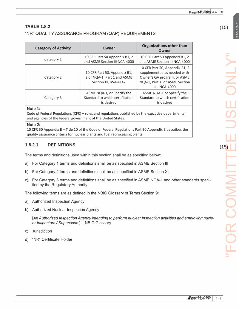
14
NB-23 2015
SECTION 1
SEC
TIO
N 1
TABLE 1.8.2 “NR” QUALITY ASSURANCE PROGRAM (QAP) REQUIREMENTS
Category of Activity Owner Organizations other than Owner
Category 1 10 CFR Part 50 Appendix B1, 2 and ASME Section III NCA-4000
10 CFR Part 50 Appendix B1, 2 and ASME Section III NCA-4000
Category 210 CFR Part 50, Appendix B1, 2 or NQA-1, Part 1 and ASME
Section XI, IWA-4142
10 CFR Part 50, Appendix B1, 2 supplemented as needed with Owner’s QA program; or ASME NQA-1, Part 1; or ASME Section
III, NCA-4000
Category 3ASME NQA-1, or Specify the
Standard to which certification is desired
ASME NQA-1,or Specify the Standard to which certification
is desiredNote 1: Code of Federal Regulations (CFR) – rules and regulations published by the executive departments and agencies of the federal government of the United States.
Note 2: 10 CFR 50 Appendix B – Title 10 of the Code of Federal Regulations Part 50 Appendix B describes the quality assurance criteria for nuclear plants and fuel reprocessing plants.
1.8.2.1 DEFINITIONS
The terms and definitions used within this section shall be as specified below:
a) For Category 1 terms and definitions shall be as specified in ASME Section III
b) For Category 2 terms and definitions shall be as specified in ASME Section XI
c) For Category 3 terms and definitions shall be as specified in ASME NQA-1 and other standards speci-fied by the Regulatory Authority
The following terms are as defined in the NBIC Glossary of Terms Section 9:
a) Authorized Inspection Agency
b) Authorized Nuclear Inspection Agency
[An Authorized Inspection Agency intending to perform nuclear inspection activities and employing nucle-ar Inspectors / Supervisors] – NBIC Glossary
c) Jurisdiction
d) “NR” Certificate Holder
(15)
(15)
"FO
RC
OM
MIT
TEE
(15)
CO
MM
ITTE
E
(15)
US
EO
NLY
"
Page 44 of 400
Page 44 of 400
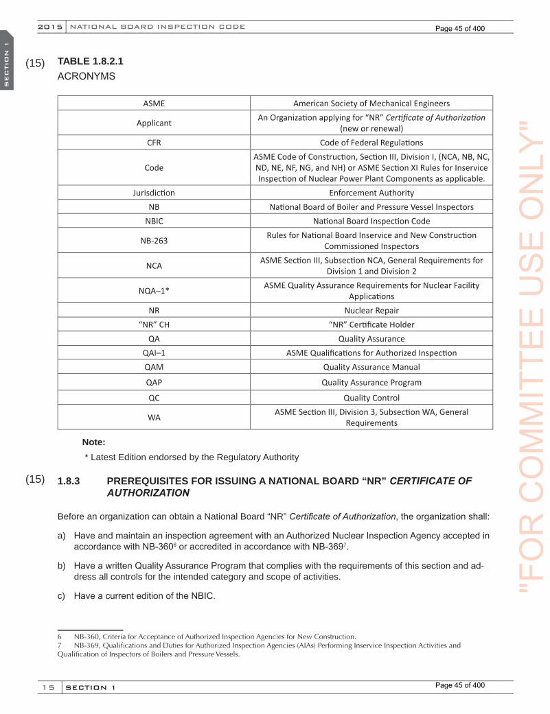
15
NATIONAL BOARD INSPECTION CODE2015
SECTION 1
SEC
TIO
N 1
TABLE 1.8.2.1 ACRONYMS
ASME American Society of Mechanical Engineers
Applicant An Organization applying for “NR” Certificate of Authorization (new or renewal)
CFR Code of Federal Regulations
CodeASME Code of Construction, Section III, Division I, (NCA, NB, NC, ND, NE, NF, NG, and NH) or ASME Section XI Rules for Inservice Inspection of Nuclear Power Plant Components as applicable.
Jurisdiction Enforcement AuthorityNB National Board of Boiler and Pressure Vessel Inspectors
NBIC National Board Inspection Code
NB-263 Rules for National Board Inservice and New Construction Commissioned Inspectors
NCA ASME Section III, Subsection NCA, General Requirements for Division 1 and Division 2
NQA–1* ASME Quality Assurance Requirements for Nuclear Facility Applications
NR Nuclear Repair“NR” CH “NR” Certificate Holder
QA Quality AssuranceQAI–1 ASME Qualifications for Authorized InspectionQAM Quality Assurance Manual
QAP Quality Assurance Program
QC Quality Control
WA ASME Section III, Division 3, Subsection WA, General Requirements
Note: * Latest Edition endorsed by the Regulatory Authority
1.8.3 PREREQUISITES FOR ISSUING A NATIONAL BOARD “NR” CERTIFICATE OF AUTHORIZATION
Before an organization can obtain a National Board “NR” Certificate of Authorization, the organization shall:
a) Have and maintain an inspection agreement with an Authorized Nuclear Inspection Agency accepted in accordance with NB-3606 or accredited in accordance with NB-3697.
b) Have a written Quality Assurance Program that complies with the requirements of this section and ad-dress all controls for the intended category and scope of activities.
c) Have a current edition of the NBIC.
6 NB-360, Criteria for Acceptance of Authorized Inspection Agencies for New Construction.7 NB-369,QualificationsandDutiesforAuthorizedInspectionAgencies(AIAs)PerformingInserviceInspectionActivitiesandQualificationofInspectorsofBoilersandPressureVessels.
(15)
(15)
"FO
RC
OM
MIT
TEE
US
EO
NLY
"
Page 45 of 400
Page 45 of 400

16
NB-23 2015
SECTION 1
SEC
TIO
N 1
d) Have available ASME Section XI, the code of construction and referenced code sections and standards appropriate for the scope of work to be performed. ASME Section XI and codes of construction (Edi-tions/Addenda) shall meet the requirements of the Regulatory Authority8 and the owner.
1.8.4 OBTAINING OR RENEWING A NATIONAL BOARD “NR” CERTIFICATE OF AUTHORIZATION
a) Before an “NR” Certificate of Authorization will be issued or renewed, the applicant must have the Quality Assurance Program and the implementation of the program reviewed and found acceptable by representatives of the National Board, the Jurisdiction, and the Authorized Nuclear Inspection Agency. The Jurisdiction will be the National Board Member Jurisdiction in which the applicant is located or the location where the Quality Assurance Program is demonstrated/implemented. At the request of the Ju-risdiction, or where there is no National Board Member Jurisdiction, the National Board representative shall act on behalf of the Jurisdiction. The implementation of the Quality Assurance Program shall be satisfactorily demonstrated by the organization. Demonstration of implementation shall meet the most stringent (classification) code requirements for the scope and category of work to be specified on the Certificate of Authorization or as requested by the applicant.
b) If the applicant is an ASME “N” type Certificate of Authorization holder, has satisfactorily demonstrat-ed within the last twelve (12) months the implementation of their Quality Assurance Program and can provide documentation that the organization is capable of implementing its Quality Assurance Program as being in compliance with this section, a further hardware verification implementation may not be necessary.
c) The Regulatory Authority or Jurisdiction, upon request to the National Board, may attend the survey process for an “NR” Certificate of Authorization to be issued or renewed.
d) The “NR” Certificate of Authorization holder shall be subject to an audit annually by the Authorized Nu-clear Inspection Agency to ensure compliance with the Quality Assurance Program.
1.8.5 QUALITY ASSURANCE PROGRAM
a) An applicant or a holder of a National Board “NR” Certificate of Authorization (“NR” Certificate Holder) shall have and maintain a written Quality Assurance Program. The Quality Assurance Program shall satisfactorily meet the requirements of this section, and Jurisdictional and Regulatory requirements as applicable. The Quality Assurance Program may be brief or voluminous, depending on the circumstanc-es. It shall be treated confidentially by the National Board and available for review by the Survey Team.
b) Each applicant or “NR” Certificate Holder is responsible for establishing and executing a Quality Assur-ance Program. The applicant or “NR” Certificate Holder may subcontract activities needed to implement the Quality Assurance Program, as limited by ASME Section III and XI, but responsibility for adherence to the Quality Assurance Program remains with the Applicant or “NR” Certificate Holder.
c) These rules set forth the requirements for planning, managing, and implementing the organization’s Quality Assurance Program to control and ensure quality is performed and maintained during repair/replacement activities of components, items, parts, and systems for nuclear facilities. These rules are to be the basis for evaluating such programs prior to the issuance or renewal of the National Board “NR” Certificate of Authorization. Rules identified in subsections 1.8.6, 1.8.7 and 1.8.8 of this section detail the Quality Assurance Program requirements for each category of activity. These rules are established to meet and follow the requirements specified in NBIC Part 3, Table 1.8.2-1 of this section.
1.8.6 QUALITY ASSURANCE PROGRAM REQUIREMENTS FOR CATEGORY 1 ACTIVITIES
8 Regulatory Authority, A government agency, such as the United States Nuclear Regulatory Commission, empowered to issueand enforce regulations concerning the design, construction, and operation of nuclear power plants.
(15)
(15)
(15)
"FO
RC
OM
MIT
TEE
(15)
CO
MM
ITTE
E
(15)
US
EO
NLY
"
Page 46 of 400
Page 46 of 400
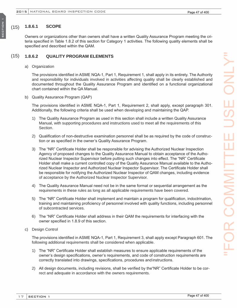
17
NATIONAL BOARD INSPECTION CODE2015
SECTION 1
SEC
TIO
N 1
1.8.6.1 SCOPE
Owners or organizations other than owners shall have a written Quality Assurance Program meeting the cri-teria specified in Table 1.8.2 of this section for Category 1 activities. The following quality elements shall be specified and described within the QAM.
1.8.6.2 QUALITY PROGRAM ELEMENTS
a) Organization
The provisions identified in ASME NQA-1, Part 1, Requirement 1, shall apply in its entirety. The Authority and responsibility for individuals involved in activities affecting quality shall be clearly established and documented throughout the Quality Assurance Program and identified on a functional organizational chart contained within the QA Manual.
b) Quality Assurance Program (QAP)
The provisions identified in ASME NQA-1, Part 1, Requirement 2, shall apply, except paragraph 301. Additionally, the following criteria shall be used when developing and maintaining the QAP.
1) The Quality Assurance Program as used in this section shall include a written Quality Assurance Manual, with supporting procedures and instructions used to meet all the requirements of this Section.
2) Qualification of non-destructive examination personnel shall be as required by the code of construc-tion or as specified in the owner’s Quality Assurance Program.
3) The “NR” Certificate Holder shall be responsible for advising the Authorized Nuclear Inspection Agency of proposed changes to the Quality Assurance Manual to obtain acceptance of the Autho-rized Nuclear Inspector Supervisor before putting such changes into effect. The “NR” Certificate Holder shall make a current controlled copy of the Quality Assurance Manual available to the Autho-rized Nuclear Inspector and Authorized Nuclear Inspector Supervisor. The Certificate Holder shall be responsible for notifying the Authorized Nuclear Inspector of QAM changes, including evidence of acceptance by the Authorized Nuclear Inspector Supervisor.
4) The Quality Assurance Manual need not be in the same format or sequential arrangement as the requirements in these rules as long as all applicable requirements have been covered.
5) The “NR” Certificate Holder shall implement and maintain a program for qualification, indoctrination, training and maintaining proficiency of personnel involved with quality functions, including personnel of subcontracted services.
6) The “NR” Certificate Holder shall address in their QAM the requirements for interfacing with the owner specified in 1.8.9 of this section.
c) Design Control
The provisions identified in ASME NQA-1, Part 1, Requirement 3, shall apply except Paragraph 601. The following additional requirements shall be considered when applicable.
1) The “NR” Certificate Holder shall establish measures to ensure applicable requirements of the owner’s design specifications, owner’s requirements, and code of construction requirements are correctly translated into drawings, specifications, procedures and instructions.
2) All design documents, including revisions, shall be verified by the“NR” Certificate Holder to be cor-rect and adequate in accordance with the owners requirements.
(15)
(15)
"FO
RC
OM
MIT
TEE
US
EO
NLY
"
Page 47 of 400
Page 47 of 400
18
NB-23 2015
SECTION 1
SEC
TIO
N 1
3) Repair/replacement plans shall be completed prior to performing any work, inspections, examina-tions or testing; however repair/replacement plans are not required for the design phase of a repair/replacement activity including activities that require design only (except rerating).
4) The repair/replacement plan shall identify any applicable Code Edition/Addenda and Code Cases, owner’s requirements and the Construction Code Edition/Addenda utilized to perform the work.
5) The repair/replacement plan shall identify expected life of the item when less than the intended life as specified in the owner’s design specification.
6) The “NR” Certificate Holder shall ensure that specifications, drawings, procedures and instructions do not conflict with the owner’s design specifications. A system must be described in the Quality As-surance Manual to resolve or eliminate such conflicts. Resolution shall consider the Design Speci-fication Requirements, as well as, the owner requirements, Jurisdictional and Regulatory Authority Requirements as applicable.
d) Procurement Document Control
The provisions identified in ASME NQA-1, Part 1, Requirement 4, shall apply. Procurement documents shall require suppliers to provide a Quality Assurance Program consistent with the applicable require-ments of ASME Section III and this section:
e) Instructions, Procedures and Drawings
The provisions identified in ASME NQA-1, Part 1, Requirement 5, shall apply. All activities affecting qual-ity shall be prescribed by documented instructions, procedures or drawings appropriate for the scope of work to be performed. Instructions, procedures or drawings shall describe acceptance criteria to ensure quality activities are accomplished.
f) Document Control
The provisions identified in ASME NQA-1, Part 1, Requirement 6, shall apply. The Quality Assurance Program shall detail measures to control the preparation, review, issuance, use, approval and distribution of all documents related to quality as identified in the applicants Quality Assurance Program. Revisions shall meet the same requirements as the originals unless the applicant specifies other measures within their program. Measures shall ensure the latest approved documents represent the repair/replacement activities performed.
g) Control of Purchased Material, Items, and Services
The provisions identified in ASME NQA-1, Part 1, Requirement 7 shall apply, except:
1) Procurement of Authorized Inspection Agency services is not applicable as specified in paragraph 507.
2) The decision to perform bid evaluation as described in paragraph 300 is the responsibility of the “NR” Certificate Holder.
3) For Certificates of Conformance specified in paragraph 503 changes, waivers, or deviations in-cluding resolution of non-conformances must meet the requirements of ASME Section III and this Section.
4) The provisions identified in ASME NQA-1, Part 1, Requirement 7, paragraph 700 are not applicable to this section.
5) Documentary evidence for items shall conform to the requirements of ASME Section III, NCA and this Section. Materials shall meet the material certification requirements as specified in ASME Sec-tion III, NCA-3800 or NCA-3970 as applicable. Documented evidence for ASME stamped items is
"FO
RC
OM
MIT
TEE
US
EO
NLY
"
Page 48 of 400
Page 48 of 400

19
NATIONAL BOARD INSPECTION CODE2015
SECTION 1
SEC
TIO
N 1
satisfied by a Manufacturer’s Data Report. Utilization of unqualified source material shall meet the requirements of ASME Section III, NCA-3855.5.
6) The “NR” Certificate Holder may obtain items from an owner, provided the owner provides the required documentation and items are identified to meet Code and the Certificate Holders Quality Assurance Program. The “NR” Certificate Holder shall not be required to audit the owner as an ap-proved supplier, provided the items used are exclusively for the owner and the owner procured and controlled the items under the owner’s Quality Assurance Program.
7) The Quality Assurance Program shall establish controls to ensure all purchased materials, items, and services conform to the requirements of the owner’s design specifications and the code of con-struction Edition/Addenda used to perform the work. Materials shall meet the requirements speci-fied in ASME Section III, NCA-3800 or NCA-3970 as applicable.
h) Identification and Control of Items
The provisions identified in ASME NQA-1, Part 1, Requirement 8, shall apply and include the following additional requirements.
1) Controls shall assure only correct and acceptable items, parts and components are used or in-stalled when performing repair/replacement activities.
2) Welding, brazing and fusing materials shall be identified and controlled.
3) Required Certified Material Test Reports and Certificates of Conformance shall be received, trace-able to the items, reviewed to comply with the material specification and found acceptable.
4) The “NR” Certificate Holder shall utilize checklists to identify required characteristics using accepted procedures, compliance with records received, results of examinations and tests performed, range of valves when required, and spaces for inclusion of document numbers and revision levels, signa-tures initials / stamps and dates of examinations or tests performed, verified, and/or witnessed by the “NR” Certificate Holder’s qualified Representative and Authorized Nuclear Inspector.
i) Control of Processes
The provisions identified in ASME NQA-1, Part 1, Requirement 9, shall apply. Documents used to control processes shall include spaces for signatures, initials, stamps and dates that activities were performed by the Certificate Holder’s representative and the Authorized Nuclear Inspector when the processes con-forms to the specified acceptance criteria as listed on drawings, procedures, instructions, specifications or other appropriate documents including revisions.
j) Examinations, Tests and Inspections
The provisions identified in ASME NQA-1, Part 1, Requirement 10, shall apply, except paragraph 700 for inspections during operations is not required.
1) A repair/replacement plan shall be described in the Quality Assurance Manual that addresses required information to perform the work needed for repair/replacement activities. Spaces shall be included for mandatory hold points where witnessing is required by the “NR” Certificate Hold-er’s Qualified Representative, the Authorized Nuclear Inspector or the owner’s representative, if required. Work shall not proceed beyond designated mandatory hold points without documented consent as appropriate.
2) The following guidance is provided for information to be included within the repair/replacement plan:
a. A detailed description of repair/replacement activities to be performed;
b. Describe any defects and examination methods used to detect the defects;
"FO
RC
OM
MIT
TEE
US
EO
NLY
"
Page 49 of 400
Page 49 of 400
20
NB-23 2015
SECTION 1
SEC
TIO
N 1
c. Defect removal method and requirements for identifying reference points;
d. Any procedures including revisions utilized; (e.g. welding, brazing, heat treat, examination, testing) and material requirements;
e. Required documentation and stamping; and
f. Acceptance criteria used to verify acceptability.
3) Repair/Replacement plans and evaluations shall be subject to review by the Jurisdictional and Reg-ulatory Authority when required.
k) Test Control
The provisions identified in ASME NQA-1, Part 1, Requirement 11 shall apply. Testing shall be performed in accordance with written test procedures with acceptance criteria clearly defined. Pre-requisites for performing each test to include calibration, equipment, trained personnel,environmental conditions and provisions for data acquisition shall be described. Test results shall be documented and evaluated by qualified personnel.
l) Control of Measuring and Test Equipment
The provisions identified in ASME NQA-1, Part 1, Requirement 12 shall apply.
1) The “NR” Certificate Holder may perform periodic checks on equipment to determine calibration is maintained. When periodic checks are used the method and frequency shall be included in the “NR” Certificate Holder’s Quality Assurance Program and if discrepancies are found, shall be re-solved to the prior periodic check.
2) The “NR” Certificate Holder may accept accreditation for calibration activities by National Volun-tary Laboratory Accreditation Program (NVLAP), American Association for Laboratory Accredita-tion (A2LA) or other accrediting body recognized by NVLAP through the International Laboratory Accreditation Cooperation (ILAC) mutual recognition arrangement (MRA) provided the following requirements are met:
a. Accreditation is to ANSI/ISO/IEC 17025:2005 “General Requirements for the Competence of Testing and Calibration Laboratories”;
b. Scope of the accreditation for the calibration laboratory covers needed measurement parame-ters, ranges and uncertainties;
c. “NR” Certificate Holder shall specify that calibration reports shall include, laboratory equipment/standards used and as found and as left data;
d. The “NR” Certificate Holder shall verify conformance to the requirements of this process; and
e. Utilization of this process shall be described and documented in the “NR” Certificate Holders QAM.
m) Handling, Storage and Shipping
The provisions of ASME NQA-1, Part 1, and Requirement 13 shall apply.
n) Quality Assurance Records
The provisions identified in ASME NQA-1, Part 1, Requirement 17, shall apply, except Paragraphs 400, 500, and 600 are not applicable. The following requirements shall be followed:
1) Records shall be identifiable and retrievable;
"FO
RC
OM
MIT
TEE
US
EO
NLY
"
Page 50 of 400
Page 50 of 400
21
NATIONAL BOARD INSPECTION CODE2015
SECTION 1
SEC
TIO
N 1
2) Records shall be retained consistent with the owners requirements for duration, location and as-signed responsibility;
3) Forms NR-1 and NVR-1 as applicable shall be completed by the “NR” Certificate Holder upon com-pletion of all repair/replacement activities. Completion of forms, registrations and stamping of the “NR” symbol stamp shall meet the requirements of NBIC Part 3, Section 5; and
4) Lifetime and non-permanent records shall be as specified in ASME Section III, NCA-4134, Tables NCA-4134.17-1, and 4134.17-2.
5) Radiographs (digital images or film) may be reproduced provided that:
a. The process shall be subject to owner’s approval;
b. The “NR” Certificate Holder is responsible for the process used and shall include a system for controlling and monitoring the accuracy so that the image will provide the same information as the original; and
c. Procedures shall contain requirements for exposure scanning, focusing, contrast, resolution and distinguishing film artifacts as applicable for reproduced images.
6) Records shall be classified, maintained and indexed and shall be accessible to the owner, owner’s designee, and the Authorized Nuclear Inspector.
7) When the “NR” Certificate Holder is the owner, designated records and reports received by the owner, shall be filed and maintained in a manner to allow access by the Authorized Nuclear Inser-vice Inspector. Suitable protection from deterioration and damage shall be provided by the owner. All records and reports shall be retained as specified in the owners QAP for the lifetime of the com-ponent or system.
o) Corrective Action
The provisions identified in ASME NQA-1, Part 1, Requirement 16 shall apply.
1) Measures shall be established to ensure that conditions adverse to quality such as failures, mal-functions, deficiencies, deviations, defective material and equipment, and other non-conformances are promptly identified and corrected.
2) In the case of significant conditions adverse to quality, the measures shall also ensure that the cause of these conditions be determined and corrected to preclude repetition. The identification of significant conditions adverse to quality, the cause, condition, and the corrective action taken shall be documented and reported to the appropriate levels of management.
3) These requirements shall also extend to the performance of subcontractors’ corrective action measures.
p) Inspection or Test Status (not to include operating status)
The provisions identified in ASME NQA-1, Part 1, Requirement 14 shall apply. Measures shall be estab-lished to indicate inspection and test status of parts, items, or components during the repair/replacement activity. The system used shall provide positive identification of the part, item, or component by means of stamps, labels, routing cards, or other acceptable methods. The system shall include any procedures or instructions necessary to achieve compliance. Procedures shall be provided for the identification of acceptable and unacceptable items and for the control of status indicators. The authority for application and removal of status indicators shall also be specified.
"FO
RC
OM
MIT
TEE
US
EO
NLY
"
Page 51 of 400
Page 51 of 400
22
NB-23 2015
SECTION 1
SEC
TIO
N 1
q) Nonconforming Materials or Items
The provisions identified in ASME NQA-1, Part 1, Requirement 15 shall apply. Measures shall be estab-lished to control materials or items that do not conform to requirements to prevent their inadvertent use, including measures to identify and control the proper installation of items and to preclude nonconfor-mance with the requirements of these rules These measures shall include procedures for identification, documentation, segregation when practical, and disposition. Nonconforming items shall be reviewed for acceptance, rejection, or repair in accordance with documented procedures. The responsibility and authority for the disposition of nonconforming items shall be defined. Repaired or replaced items shall be re-examined in accordance with the applicable procedures. Measures that control further processing of a nonconforming or defective item, pending a decision on its disposition, shall be established and main-tained. Ultimate disposition of nonconforming items shall be documented.
r) Audits
The provisions identified in ASME NQA-1, Part 1, and Requirement 18 shall apply and shall include the following:
A comprehensive system of planned and periodic internal audits shall be performed by the “NR” Certif-icate Holder. Audit frequency shall be specified in the organization’s Quality Assurance Manual. Audits shall be conducted at least annually for any ongoing code activity to verify compliance with Quality Assur-ance Program requirements, performance criteria and to determine the effectiveness of the Quality As-surance Program. When no code work has been performed, the required annual audit need only include those areas of responsibility required to be continually maintained such as training, audits, organizational structure, and Quality Assurance Program revisions. The Quality Assurance Manual shall as a minimum describe the following:
1) Audits shall be performed in accordance with written procedures or checklists by qualified audit personnel not having direct responsibility in areas being audited;
2) Audit personnel shall be qualified in accordance with the current requirements of ASME NQA-1;
3) Audit results shall be documented and reviewed by responsible management;
4) Requirements for follow-up actions shall be specified for any deficiencies noted during the audit;
5) Audit records and applicable documentation shall be made available to the Authorized Nuclear Inspector for review;
6) Audit records shall include as a minimum;
a. Written procedures;
b. Checklists;
c. Reports;
d. Written replies; and
e. Completion of corrective actions.
s) Authorized Nuclear Inspector
Measures shall be taken to reference the commissioned rules for National Board Authorized Nuclear Inspector, in accordance with NB-263 Rules for National Board Inservice and New Construction Com-missioned Inspectors. The “NR” Certificate Holder shall ensure that the latest documents including the Quality Assurance Manual, procedures and instructions are made available to the Authorized Nuclear Inspector. The Authorized Nuclear Inspector shall be consulted prior to the issuance of a repair/replace-ment plan by the “NR” Certificate Holder in order that the Authorized Nuclear Inspector may select any
"FO
RC
OM
MIT
TEE
US
EO
NLY
"
Page 52 of 400
Page 52 of 400

23
NATIONAL BOARD INSPECTION CODE2015
SECTION 1
SEC
TIO
N 1
in-process inspection or hold points when performing repair/replacement activities. The “NR” Certificate Holder shall keep the Authorized Nuclear Inspector informed of progress of the repair/replacement activ-ity so that inspections may be performed. The Authorized Nuclear Inspector shall not sign Form NR-1 or Form NVR-1, as applicable, unless satisfied that all work carried out is in accordance with this Section. The Authorized Nuclear Inspector and Authorized Nuclear Inspector Supervisor shall have access to areas where work is being performed including subcontractors facilities in order to perform their required duties. The ANI shall be involved in dispositions and verification for non-conformances and corrective actions involving quality or code requirements.
t) Exhibits
Forms and exhibits referenced in the Quality Assurance Manual shall be explained in the text and in-cluded as part of the referencing document or as an appendix to the Quality Assurance Manual. Forms shall be controlled and identified to show the latest approved revision, name, and other corresponding references as stated in the Quality Assurance Manual.
1.8.7 QUALITY ASSURANCE PROGRAM REQUIREMENTS FOR CATEGORY 2 ACTIVITIES
1.8.7.1 SCOPE
Owners or organizations other than owners shall have a written Quality Assurance Program meeting one of the criteria specified in Table 1.8.2 of this section. Organizations applying for a Category 2 “NR” Certificate of Authorization shall specify in their written Quality Assurance Program which program criteria their Quality Assurance Program follows. Owners shall have a Quality Assurance Program meeting the requirements of ei-ther 10 CFR 50, Appendix B or NQA-1 Part 1 and shall include the additional requirements specified in ASME Section XI, IWA-4142 when applicable. Organizations other than the owner shall comply with requirements specified in either 10 CFR 50, Appendix B supplemented as needed with the owner’s QAP; NQA-1 Part 1; or NCA-4000. Organizations may elect to choose to follow all the rules specified in one of the allowed QAP criteria specified in Table 1.8.2 or they may elect to combine or supplement requirements from other specified QAP’s. When organizations elect to combine QAP requirements, it shall be clearly specified and understood in the QAM which QAP requirement is being followed for each activity specified in their QAM. The following quality elements shall be specified and described within the QAM.
1.8.7.2 QUALITY PROGRAM ELEMENTS
a) Organization
The authority and responsibility for individuals involved in activities affecting quality shall be clearly estab-lished and documented throughout the Quality Assurance Program and identified on a functional organi-zational chart contained within the QA Manual.
b) Quality Assurance Program (QAP)
1) Qualification of non-destructive examination personnel shall be as required by the code or as speci-fied in the owner’s Quality Assurance Program.
2) Prior to returning an item to service, the owner shall evaluate the suitability of the item subjected to the repair/replacement activity. Corrective actions shall be taken when an item is determined to be deficient or does not satisfy the requirements of this section.
3) The “NR” Certificate Holder shall provide a copy of the Quality Assurance Manual to the owner for review and acceptance. The “NR” Certificate Holder shall make a current controlled copy of the Quality Assurance Manual available to the Authorized Nuclear Inspector and Authorized Nuclear Inspector Supervisor. When a repair/replacement activity is split between the owner and an “NR”
(15)
(15)
(15)
"FO
RC
OM
MIT
TEE
US
EO
NLY
"
Page 53 of 400
Page 53 of 400

24
NB-23 2015
SECTION 1
SEC
TIO
N 1
Certificate Holder, each Quality Assurance Program shall comply with this section for their respec-tive activities. The owner shall establish interfaces for assuring this section is met for the two Quali-ty Assurance Programs.
4) The “NR” Certificate Holder shall be responsible for advising the Authorized Nuclear Inspection Agency of proposed changes to the Quality Assurance Manual to obtain acceptance of the Autho-rized Nuclear Inspector Supervisor before putting such changes into effect. The Certificate Holder shall be responsible for notifying the Authorized Nuclear Inspector of QAM changes, including evidence of acceptance by the Authorized Nuclear Inspector Supervisor.
5) The Quality Assurance Manual need not be in the same format or sequential arrangement as the requirements in these rules as long as all applicable requirements have been covered.
6) The “NR” Certificate Holder shall implement and maintain a program for qualification, indoctrination, training and maintaining proficiency of personnel involved with quality functions, including personnel of subcontracted services.
7) The “NR” Certificate Holder shall address in their QAM the requirements for interfacing with the owner specified in 1.8.9 of this section.
c) Design Control
1) Repair/replacement activities, code edition and addenda used shall correspond with the owner’s Inservice Inspection Program unless later code editions and addenda have been accepted by the owner, the Enforcement and/or the Regulatory authority having jurisdiction at the plant site.
2) The repair/replacement plan [see 1.8.7.2 j)] shall identify expected life of the item when less than the intended life as specified in the owner’s requirements and the owner shall be advised of the condition.
3) The “NR” Certificate Holder shall assure that specifications, drawings, procedures and instructions do not conflict with the owner’s requirements. A system must be described in the Quality Assurance Manual to resolve or eliminate such conflicts. Resolution shall consider the design specification requirements, as well as, the owner Requirements, Jurisdictional and Regulatory requirements as applicable.
4) ASME Section XI establishes that the owner is responsible for design in connection with repair/replacement activities. The “NR” Certificate Holder must ensure that the design specification, drawings, or other specifications or instructions furnished by the owner satisfy the code edition and addenda of the owner’s requirements. To satisfy this requirement, the “NR” Certificate Holder shall establish requirements that correctly incorporate the owner’s requirements into their specifications, drawings, procedures, and instructions, which may be necessary to carry out the work. The “NR” Certificate Holder’s system shall include provisions to ensure that the appropriate quality standards are specified and included in all quality records. These records shall be reviewed for compliance with the owner’s requirements and the requirements of ASME Section XI.
d) Procurement Document Control
Procurement documents shall require suppliers to provide a Quality Assurance Program consistent with the applicable requirements of ASME Section III, NCA and this section. Documents for procurement of materials, items, and subcontracted services shall include requirements to the extent necessary to en-sure compliance with the owner’s requirements and IWA-4000 of ASME Section XI. To the extent neces-sary, procurement documents shall require suppliers to maintain a Quality Assurance Program consistent with the applicable requirements of the edition and addenda of the code of construction to which the items are constructed. Measures shall be established to ensure that all purchased material, items, and services conform to these requirements.
"FO
RC
OM
MIT
TEE
US
EO
NLY
"
Page 54 of 400
Page 54 of 400
25
NATIONAL BOARD INSPECTION CODE2015
SECTION 1
SEC
TIO
N 1
e) Procedures and Drawings
Repair/replacement plans and any verification of acceptability (evaluations) shall be subject to review by Jurisdiction and Regulatory Authorities having jurisdiction at the plant site. Activities affecting quality shall be prescribed by documented instructions, procedures or drawings of a type appropriate to the circum-stances and shall be accomplished in accordance with these instructions, procedures, or drawings. In-structions, procedures, or drawings shall include appropriate quantitative and qualitative criteria for deter-mining that activities affecting quality have been satisfactorily accomplished. The “NR” Certificate Holder shall maintain a written description of procedures, instructions, or drawings used by the organization for control of quality and examination requirements detailing the implementation of the Quality Assurance Program requirements. Copies of these procedures shall be readily available to the Authorized Nuclear Inspector and Authorized Nuclear Inservice Inspector, as applicable.
f) Document Control
The program shall include measures to control the issuance, use, and disposition of documents, such as specifications, instructions, procedures, and drawings, including changes thereto. These measures shall ensure that the latest applicable documents, including changes, are reviewed for adequacy and approved for release by authorized personnel and distributed for use at the location where the prescribed activity is performed.
g) Control of Purchased Material, Items, and Services
When the owner performs repair/replacement activities, purchase of materials and small products shall meet the requirements specified in ASME Section XI, IWA 4142. Measures shall be established to ensure that purchased material, items, and services conform to the owner’s requirements and applicable edition and addenda of the code of construction and ASME Section XI. These measures shall include identifica-tion for material traceability. Provisions shall be identified for source evaluation and objective evidence shall be provided evidencing quality standards for material examination upon receipt.
h) Identification and Control of Items
1) Measures shall be established for identification and control of material and items, including partially fabricated assemblies. These measures shall ensure that identification is maintained and trace-able, either on the material or component, or on records throughout the repair/replacement activity. These measures shall be designed to prevent the use of incorrect or defective items and those which have not received the required examinations, tests, or inspections.
2) Identification for traceability shall be applied using methods and materials that are legible and not detrimental to the component or system involved. Such identification shall be located in areas that will not interfere with the function or quality aspects of the item.
3) Certified Material Test Reports shall be identified as required by the applicable material specification in ASME Section II and shall satisfy any additional requirements specified in the original code of construction. The Certified Material Test Report or Certificate of Compliance need not be duplicated for submission with compliance documents when a record of compliance and satisfactory reviews of the Certified Material Test Report and Certificate of Compliance is provided. Quality documents shall provide a record that the Certified Material Test Report and Certificate of Compliance have been received, reviewed, and found acceptable. When the “NR” Certificate Holder authorizes a subcontracted organization to perform examinations and tests in accordance with the original code of construction, the “NR” Certificate Holder shall certify compliance either on a Certified Material Test Report or Certificate of Compliance that the material satisfies the original code of construction requirements.
"FO
RC
OM
MIT
TEE
US
EO
NLY
"
Page 55 of 400
Page 55 of 400
26
NB-23 2015
SECTION 1
SEC
TIO
N 1
i) Control of Processes
1) The “NR” Certificate Holder shall operate under a controlled system such as process sheets, checklists, travelers, plans or equivalent procedures. Measures shall be established to ensure that processes such as welding, nondestructive examination, and heat treating are controlled in accor-dance with the rules of the applicable section of the ASME Code and are accomplished by qualified personnel using qualified procedures.
2) Process sheets, checklists, travelers, or equivalent documentation shall be prepared, including the document numbers and revisions to which the process conforms with space provided for reporting results of completion of specific operations at checkpoints of repair/replacement activities.
j) Examinations, Tests and Inspections
1) A repair/replacement plan shall be prepared in accordance with the Quality Assurance Program whenever repair/replacement activities are performed. As a minimum, the repair/replacement plan shall include the requirements specified in ASME Section XI, IWA-4150.
2) In-process and final examinations and tests shall be established to ensure conformance with spec-ifications, drawings, instructions, and procedures which incorporate or reference the requirements and acceptance criteria contained in applicable design documents. Inspection, test and examination activities to verify the quality of work shall be performed by persons other than those who per-formed the activity being examined. Such persons shall not report directly to the immediate supervi-sors responsible for the work being examined.
3) Process sheets, travelers, or checklists shall be prepared, including the document numbers and re-vision to which the examination or test is to be performed, with space provided for recording results.
4) Mandatory hold/inspection points at which witnessing is required by the “NR” Certificate Holder’s representative or the Authorized Nuclear Inspector/Authorized Nuclear Inservice Inspector shall be indicated in the controlling documents. Work shall not proceed beyond mandatory hold/inspection points without the consent of the “NR” Certificate Holder’s representative or the Authorized Nuclear Inspector/Authorized Nuclear Inservice Inspector, as applicable.
k) Test Control
1) Testing shall be performed in accordance with the owner’s written test procedures that incorporate or reference the requirements and acceptance criteria contained in applicable design documents.
2) Test procedures shall include provisions for ensuring that prerequisites for the given test have been met, that adequate instrumentation is available and used, and that necessary monitoring is performed. Prerequisites may include calibrated instrumentation, appropriate equipment, trained personnel, condition of test equipment, the item to be tested, suitable environmental conditions, and provisions for data acquisition.
3) Test results shall be documented and evaluated to ensure that test requirements have been satisfied.
l) Control of Measuring and Test Equipment
Measures shall be established and documented to ensure that tools, gages, instruments, and other mea-suring and testing equipment and devices used in activities affecting quality are of the proper range, type, and accuracy to verify conformance to established requirements. A procedure shall be in effect to ensure that they are calibrated and properly adjusted at specified periods or use intervals to maintain accuracy within specified limits. Calibration shall be traceable to known national standards, where these standards exist, or with the device manufacturer’s recommendation.
"FO
RC
OM
MIT
TEE
US
EO
NLY
"
Page 56 of 400
Page 56 of 400
27
NATIONAL BOARD INSPECTION CODE2015
SECTION 1
SEC
TIO
N 1
m) Handling, Storage and Shipping
Measures and controls shall be established to maintain quality requirements for handling, storage, and shipping of parts, materials, items, and components.
n) Quality Assurance Records
Documentation, reports and records shall be in accordance with ASME Section XI, IWA-6000.
1) The owner is responsible for designating records to be maintained. Measures shall be established for the “NR” Certificate Holder to maintain these records [See 1.8.7.2 n) 2)] required for Quality Assurance of repair/replacement activities. These shall include documents such as records of materials, manufacturing, examination, and test data taken before and during repair/replacement activity. Procedures, specifications, and drawings used shall be fully identified by pertinent material or item identification numbers, revision numbers, and issue dates. The records shall also include related data such as personnel qualification, procedures, equipment, and related repairs. The “NR” Certificate Holder shall take such steps as may be required to provide suitable protection from deterioration and damage for records while in his care. Also, it is required that the “NR” Certificate Holder have a system for correction or amending records that satisfies the owner’s requirements. These records may be either the original or a reproduced, legible copy and shall be transferred to the owner at his request.
2) Records to be maintained as required in NBIC Part 3, 1.8.7.2 n) 1) above shall include the follow-ing, as applicable:
a. An index that details the location and individual responsible for maintaining the records;
b. Manufacturer’s Data Reports, properly executed, for each replacement component, part, appur-tenance, piping system, and piping assembly, when required by the design specification or the owner;
c. The required as-constructed drawings certified as to correctness;
d. Copies of applicable Certified Material Test Reports and Certificates of Compliance;
e. As-built sketch(es) including tabulations of materials repair/replacement procedures, and in-structions to achieve compliance with ASME Section XI;
f. Nondestructive examination reports, including results of examinations, shall identify the ASNT, SNT-TC-1A, CP-189, or ACCP certification level of personnel interpreting the examination re-sults. Final radiographs shall be included where radiography has been performed. Radiographs may be microfilmed or digitally reproduced. The accuracy of the reproduction process shall be verified and monitored for legibility, storage, retrievability and reproduction quality;
g. Records of heat treatments may be either the heat treatment charts or a summary description of heat treatment time and temperature data certified by the “NR” Certificate Holder. Heat treat-ments performed by the material manufacturer to satisfy requirements of the material specifica-tions may be reported on the Certified Material Test Report; and
h. Nonconformance reports shall satisfy IWA-4000 of ASME Section XI and shall be reconciled by the owner prior to certification of the Form NR-1 or NVR-1, as applicable.
3) After a repair/replacement activity, all records including audit reports required to verify compliance with the applicable engineering documents and the “NR” Certificate Holder’s Quality System Pro-gram, shall be maintained at a place mutually agreed upon by the owner and the “NR” Certificate Holder. The “NR” Certificate Holder shall maintain records and reports for a period of five years after completion of the repair/replacement activity.
"FO
RC
OM
MIT
TEE
US
EO
NLY
"
Page 57 of 400
Page 57 of 400
28
NB-23 2015
SECTION 1
SEC
TIO
N 1
4) When the “NR” Certificate Holder is the owner, designated records and reports received by the owner, shall be filed and maintained in a manner to allow access by the Authorized Nuclear Inser-vice Inspector. Suitable protection from deterioration and damage shall be provided by the owner. These records and reports shall be retained as specified in the owners QAP for the lifetime of the component or system.
5) The original of the completed Form NR-1 or Form NVR-1, as applicable, shall be registered with the National Board and, if required, a copy forwarded to the Jurisdiction where the nuclear power plant is located.
o) Corrective Action
1) Measures shall be established to ensure that conditions adverse toquality such as failures, malfunc-tions, deficiencies, deviations, defective material and equipment, and other nonconformances are promptly identified, controlled and corrected.
2) In the case of significant conditions adverse to quality, the measures shall also ensure that the cause of these conditions be determined and corrected to preclude repetition. The identification of significant conditions adverse to quality, the cause, condition, and the corrective action taken shall be documented and reported to the appropriate levels of management.
3) Corrective action requirements shall also extend to the performance of subcontractors’ activities.
p) Inspection or Test Status (not to include operating status)
Measures shall be established to indicate examination and test status of parts, items, or components during the repair/replacement activity. The system used shall provide positive identification of the part, item, or component by means of stamps, labels, routing cards, or other acceptable methods. The system shall include any procedures or instructions necessary to achieve compliance. Also, measures shall be provided for the identification of acceptable and unacceptable items. They shall also include procedures for control of status indicators, including the authority for application and removal of status indicators.
q) Nonconforming Materials or Items
Measures shall be established to control materials or items that do not conform to requirements to pre-vent their inadvertent use, including measures to identify and control the proper installation of items and to preclude nonconformance with the requirements of these rules. These measures shall include proce-dures for identification, documentation, segregation, and disposition. Nonconforming items shall be re-viewed for acceptance, rejection, or repair in accordance with documented procedures. The responsibility and authority for the disposition of nonconforming items shall be defined. Repaired/replaced or altered items shall be re-examined in accordance with the applicable procedures.
Measures that control further processing of a nonconforming or defective item, pending a decision on its disposition, shall be established and maintained. Ultimate disposition of nonconforming items shall be documented.
r) Audits
A comprehensive system of planned and periodic internal audits shall be performed by each organization, Audit frequency shall be specified in the organization’s Quality Assurance Manual. Audits shall be con-ducted at least annually to verify compliance with Quality Assurance Program requirements, performance criteria and to determine the effectiveness of the Quality Assurance Program. When no code work has been performed, the required annual audit need only include those areas of responsibility required to be continually maintained such as training, audits, organizational structure, Quality Assurance Program revisions, etc. The Quality Assurance Manual shall as a minimum describe the following:
1) Audits shall be performed in accordance with written procedures or checklists by qualified audit personnel not having direct responsibility in areas being audited;
"FO
RC
OM
MIT
TEE
US
EO
NLY
"
Page 58 of 400
Page 58 of 400

29
NATIONAL BOARD INSPECTION CODE2015
SECTION 1
SEC
TIO
N 1
2) Audit personnel shall be qualified in accordance with the current requirements of NQA-1;
3) Audit results shall be documented and reviewed by responsible management;
4) Requirements for follow-up actions for any deficiencies noted during the audit;
5) Audit records and applicable documentation shall be made available to the Authorized Nuclear Inspector for review;
6) Audit records shall include as a minimum:
a. written procedures;
b. checklists;
c. reports;
d. written replies; and
e. completion of corrective actions.
s) Authorized Nuclear Inspector
Measures shall be taken to reference the commissioned rules for National Board Authorized Nuclear Inspector, in accordance with NB-263 Rules for National Board Inservice and New Construction Com-missioned Inspectors. The “NR” Certificate Holder shall ensure that the latest documents including the Quality Assurance Manual, procedures and instructions are made available to the Authorized Nuclear Inspector. The Authorized Nuclear Inspector shall be consulted prior to the issuance of a repair/replace-ment plan by the “NR” Certificate Holder in order that the Authorized Nuclear Inspector may select any in process inspection or hold points when performing repair/replacement activities. The “NR” Certificate Holder shall keep the Authorized Nuclear Inspector informed of progress of the repair/replacement activ-ity so that inspections may be performed. The Authorized Nuclear Inspector shall not sign Form NR-1 or Form NVR-1, as applicable, unless satisfied that all work carried out is in accordance with this section. The Authorized Nuclear Inspector and Authorized Nuclear Inspector Supervisor shall have access to areas where work is being performed including subcontractors facilities in order to perform their required duties. The ANI shall be involved in dispositions and verification for nonconformances and corrective actions involving quality or code requirements.
t) Exhibits
Forms and exhibits referenced in the Quality Assurance Manual shall be explained in the text and in-cluded as part of the referencing document or as an appendix to the Quality Assurance Manual. Forms shall be controlled and identified to show the latest approved revision, name, and other corresponding references as stated in the Quality Assurance Manual.
1.8.8 QUALITY ASSURANCE PROGRAM REQUIREMENTS FOR CATEGORY 3 ACTIVITIES
1.8.8.1 SCOPE
Organizations requesting a Category 3 “NR” Certificate of Authorization may elect to follow the require-ments specified in ASME NQA-1 Part 1 or follow specific Quality Assurance Program requirements out-lined in other specified standards as required by the owner, Regulatory Authority or Jurisdiction. Organi-zations shall specify in the QAM what QAP requirements are followed. When standards other than ASME NQA-1 are followed, the organization shall have available a copy of that standard for review by the NB Survey Team and the ANIA, as applicable. Each organization shall, as a minimum, include in their written QAM the specified elements listed in Category 1 and/or 2 (1.8.6, 1.8.7) QAP requirements. Additional
(15)
(15)
"FO
RC
OM
MIT
TEE
US
EO
NLY
"
Page 59 of 400
Page 59 of 400
30
NB-23 2015
SECTION 1
SEC
TIO
N 1
requirements, as specified within NBIC Part 3, 1.8.8 and 1.8.9 shall be included within the QAP. Also, limitations or additions to ASME NQA-1, as specified for Category 1 or 2 may be incorporated and refer-enced within the QAM.
1.8.8.2 QUALITY PROGRAM ELEMENTS
a) Organization
Persons and organization shall have authority and freedom to identify quality problems; initiate, recom-mend or provide solutions and verify implementation of solutions.
b) QAP
Shall account for special controls, processes, test equipment, tools and skills to obtain quality and for verification of quality by inspections and tests. Indoctrination, training and maintaining proficiency of personnel effecting quality shall be described. The status and adequacy of the QAP shall be regularly reviewed. The scope shall be included within the written QAM. The “NR” Certificate Holder shall make a current controlled copy of the Quality Assurance Manual available to the Authorized Nuclear Inspector and Authorized Nuclear Inspector Supervisor. The “NR” Certificate Holder shall address in their QAM the requirements for interfacing with the owner specified in 1.8.9 of this section.
c) Design Control
Established measures to assure approximate quality standards are specified and included in design doc-uments. Any deviations shall be identified and controlled.
d) Document Control
Documents for procurement of material, equipment and services shall ensure regulatory requirements, design bases and other quality requirements and are included or referenced. Procurement documents shall require contractors or subcontractors provide a Quality Assurance Program consistent with the pro-visions specified in this NBIC Part 3, 1.8.8.
e) Instructions, Procedures and Drawings
Activities affecting quality shall be accomplished in accordance with prescribed instructions, procedures or drawings and shall include approximate quantitative or qualified acceptance criteria to determine ac-tivities are satisfactorily accomplished.
f) Document Control
Shall define measures to control the preparation, issuance, use, approval, revisions and distribution of all documents related to quality.
g) Control of Purchases, Materials, Items and Services
Purchased material, items and services shall conform to the procurement documents. Measures shall be established for source evaluation and selection, objective evidence of quality, inspections at the source and examination of products upon delivery. Effectiveness of quality shall be assessed by the applicant or designee at specified intervals.
h) Identification and Control of Items
Specified controls shall ensure only correct and acceptable items, parts and components are used and installed.
"FO
RC
OM
MIT
TEE
US
EO
NLY
"
Page 60 of 400
Page 60 of 400

31
NATIONAL BOARD INSPECTION CODE2015
SECTION 1
SEC
TIO
N 1
Control of Processes
Documents used to control processes and conform to specified acceptance criteria shall include spaces for signatures, initials, stamps and dates for activities performed by the Certificate Holders’ representative and the Authorized Nuclear Inspector.
i) Examinations, Tests and Inspections
A repair / replacement plan shall address all required information for performing examinations, tests and inspections including but not limited to:
1) Establishing hold points
2) Identifying procedures, methods, acceptance criteria
3) Defects identified, removal methods, welding and material requirements, reference points used for identification
4) Evaluations of results
j) Test Control
Tests performed to written procedures identifying acceptance limits, calibration, equipment, personnel qualifications, environmental conditions, and documentation required.
k) Control of Measuring and Test Equipment
Procedures, methods and frequency of calibration shall be described for all types of measuring and test equipment used to verify quality. Any discrepancies shall be identified and resolved.
l) Handling, Storage and Shipping
Processes or procedures shall be established to prevent damage, deterioration or misuse of material, items or components used and stored.
m) Records
All quality related records shall be classified, identified, verified, maintained, distributed, retraceable, and accessible. When the “NR” Certificate Holder is the owner, designated records and reports received by the owner, shall be filed and maintained in a manner to allow access by the Authorized Nuclear Inser-vice Inspector (ANII). Suitable protection from deterioration and damage shall be provided by the owner. These records and reports shall be retained as specified in the owner’s QAP for the lifetime of the com-ponent or system.
n) Corrective Action
Measures established to assure conditions adverse to quality are promptly identified and corrected and action taken to preclude repetition.
o) Inspection or Test Status
Measures shall be established to indicate inspection and test status of parts, items or components during repair/replacement activity. Measures shall include identification, procedures, control indicators (accept-able, unacceptable) and responsibility of personnel.
p) Nonconforming Material or Items
Measures to control material or items, nonconforming to specified criteria shall be established. Measures shall include identifying, controlling, documenting, reviewing, verifying, dispositioning and segregation when practical.
"FO
RC
OM
MIT
TEE
US
EO
NLY
"
Page 61 of 400
Page 61 of 400
32
NB-23 2015
SECTION 1
SEC
TIO
N 1
q) Audits
A system of planned and periodic audits shall be established to verify compliance of the Quality Assurance Program. Audits shall include; written procedures, checklists, trained/qualified personnel not having direct responsibility for areas being audited, documentation, review by management and follow up actions when required.
r) Authorized Nuclear Inspector
Qualifications and duties shall be as specified in ASME QAI-1 and NB-263 for the Authorized Inspection Agencies, Authorized Nuclear Inspector and the Authorized Nuclear Inspector Supervisor. Additional requirements are specified in Sections 1.8.6.2 s), 1.8.7.2 s), and 1.8.9.
s) Exhibits
Quality related forms and exhibits described in the Quality Assurance Program shall be identified, con-trolled and where applicable included as a reference document within the QAM or referenced procedures.
1.8.9 INTERFACE WITH THE OWNER’S REPAIR/REPLACEMENT PROGRAM (FOR CATEGORIES 1, 2, AND 3 AS APPLICABLE)
Interface with the owner’s repair/replacement program shall meet the following:a) The “NR” Certificate Holder’s repair/replacement plan shall be subject to the acceptance of the owner
and the owner’s Authorized Nuclear Inservice Inspector (ANII) and shall be subject to review by the Jurisdiction and Regulatory Authorities having jurisdiction at the plant site.
b) Repair/Replacement activities of nuclear components shall meet the requirements of ASME Section III, ASME Section XI, and/or other applicable standard, and the owner’s requirements, and shall be subject to verification by the Jurisdiction and Regulatory Authorities having jurisdiction at the plant site.
c) Documentation of the repair/replacement activities of nuclear components shall be recorded on the Re-port of Repair/Replacement Activities of Nuclear Components and Systems for Nuclear Facilities, Form NR-1, or Report of Repair/Replacement Activities for Nuclear Pressure Relief Devices, Form NVR-1, in accordance with the NBIC Part 3, Section 5. The completed forms shall be signed by a representative of the “NR” Certificate Holder and the Authorized Nuclear Inspector when the repair/replacement activity meets the requirements of this section. For repair/replacement activities that involve design changes, Form NR-1, or Form NVR-1, as applicable, shall indicate the organization responsible for the design or design reconciliation in accordance with the owner’s requirements.
d) The “NR” Certificate Holder shall provide a copy of the signed Form NR-1 or Form NVR-1, as appli cable, to the owner, the Enforcement, and the Regulatory Authority if required, and the Authorized Nu-clear Inspection Agency. The original Form NR-1 or Form NVR-1, as applicable, shall be registered with the National Board by the “NR” Certificate Holder. A NB registration log shall be maintained by the “NR” Certificate Holder. See NBIC Part 3, Section 5.5 and 5.6.
e) The “NR” Certificate Holder shall provide a nameplate/stamping for repair/replacement activities for each nuclear component unless otherwise specified by the owner’s Quality Assurance Program. The required information and format shall be as shown in NBIC Part 3, Section 5.
(15)
"FO
RC
OM
MIT
TEE
US
E(15)
US
E(15)
ON
LY"
Page 62 of 400
Page 62 of 400
33
NATIONAL BOARD INSPECTION CODE2015
SECTION 2
SEC
TIO
N 2
PART 3, SECTION 2 REPAIRS AND ALTERATIONS — WELDING AND HEAT TREATMENT
2.1 SCOPE
This section provides general and specific requirements for welding and heat treating when performing weld-ed repairs and alterations to pressure-retaining items. Careful consideration shall be given to pressure-re-taining items that have been fabricated of either creep strength enhanced ferritic materials or ferritic materials enhanced by heat treatment. The tensile and creep strength properties of these materials can be degraded by not following specific welding and heat treatment requirements. The user is cautioned to seek technical guidance for welding and heat treating requirements in accordance with the original code of construction.
2.2 WELDING
Welding shall be performed in accordance with the requirements of the original code of construction used for the pressure-retaining item whenever possible.
2.2.1 WELDING PROCEDURE SPECIFICATIONS
Welding shall be performed in accordance with Welding Procedure Specifications (WPS) qualified in accor-dance with the original code of construction or the construction standard or code selected. When this is not possible or practicable, the WPS may be qualified in accordance with ASME Section IX.
2.2.2 STANDARD WELDING PROCEDURE SPECIFICATIONS (SEE NBIC PART 3, 2.3)
An “R” Certificate Holder may use one or more applicable Standard Welding Procedure Specifications (SWPS) shown in NBIC Part 3, Table 2.3 without supporting Procedure Qualification Records (PQRs) since SWPS are pre-qualified.
2.2.3 PERFORMANCE QUALIFICATION
Welders and welding operators shall be qualified for the welding processes that are used. Such qualification shall be in accordance with the requirements of the original code of construction, the construction standard, code selected or ASME Section IX. Use of a Standard Welding Procedure Specification shown in NBIC Part 3, 2.3 is permitted for performance qualification testing.
2.2.4 WELDING RECORDS
The “R” Certificate Holder shall maintain a record of the results obtained in Welding Procedure Qualifications, except for those qualifications for which the provisions of NBIC Part 3, 2.2.2 are used and of the results ob-tained in welding performance qualifications. These records shall be certified by the “R” Certificate Holder and shall be available to the Inspector.
2.2.5 WELDER’S IDENTIFICATION
The “R” Certificate Holder shall establish a system for the assignment of a unique identification mark to each welder/welding operator qualified in accordance with the requirements of the NBIC. The “R” Certificate Hold-er shall also establish a written procedure whereby welded joints are identified as to the welder or welding operator who made them. This procedure shall use one or more of the following methods and be acceptable to the Inspector. The welder’s or welding operator’s identification mark may be stamped (low stress stamp)
"FO
RC
OM
MIT
TEE
US
EO
NLY
"
Page 63 of 400
Page 63 of 400
34
2015
SECTION 2
SEC
TIO
N 2
NB-23
adjacent to welded joints made by the individual, or the “R” Certificate Holder may keep a documented record of welded joints and the welders or welding operators used in making the joints.
2.2.6 WELDER’S CONTINUITY
The performance qualification of a welder or welding operator shall be affected when one of the following conditions occur:
a) When the welder or welding operator has not welded using a specific process during a period of six months or more, their qualifications for that process shall expire; or
b) When there is specific reason to question a welder’s ability to make welds that meet the specification, the qualification which supports the welding that is being performed shall be revoked. All other qualifi-cations not questioned remain in effect.
2.2.6.1 WELDER’S CONTINUITY RECORDS
a) The “R” Certificate Holder shall maintain a welding continuity record and shall make the record available to the Inspector.
b) The method of recording welding continuity and the record retention period shall be described in the “R” Certificate Holder’s Quality System Manual.
c) When there is specific reason to question a welder’s ability to make welds that meet the specification, the qualification which supports the welding that is being performed shall be revoked. All other qualifica-tions not questioned remain in effect.
2.3 STANDARD WELDING PROCEDURE SPECIFICATIONS
One or more SWPSs from NBIC Part 3, Table 2.3 may be used as an alternative to one or more WPS doc-uments qualified by the organization making the repair or alteration, provided the organization accepts by certification (contained therein) full responsibility for the application of the SWPS in conformance with the application as stated in the SWPS. When using SWPSs, all variables listed on the Standard Welding Pro-cedure are considered essential and, therefore, the repair organization cannot deviate, modify, amend, or revise any SWPSs. US Customary Units or metric units may be used for all SWPSs in NBIC Part 3, Table 2.3, but one system shall be used for application of the entire SWPS in accordance with the metric conversation table contained in the SWPS. The user may issue supplementary instructions as allowed by the SWPS. Standard Welding Procedures Specifications shall not be used in the same product joint together with the other Standard Welding Procedure Specifications or other welding procedure specifications qualified by the organization.
The AWS reaffirms SWPSs in accordance with ANSI procedures. When reaffirmation occurs without revision to the SWPS, the letter “R” is added to the SWPS designation following the year. Such designation is consid-ered to be identical with the previously published version and may be used pending incorporation herein, on the same basis as the version listed in NBIC Part 3, Table 2.3.
"FO
RC
OM
MIT
TEE
US
EO
NLY
"O
NLY
"O
NLY
"S
EC
TIO
N 2
ON
LY"
SEC
TIO
N 2
Page 64 of 400
Page 64 of 400
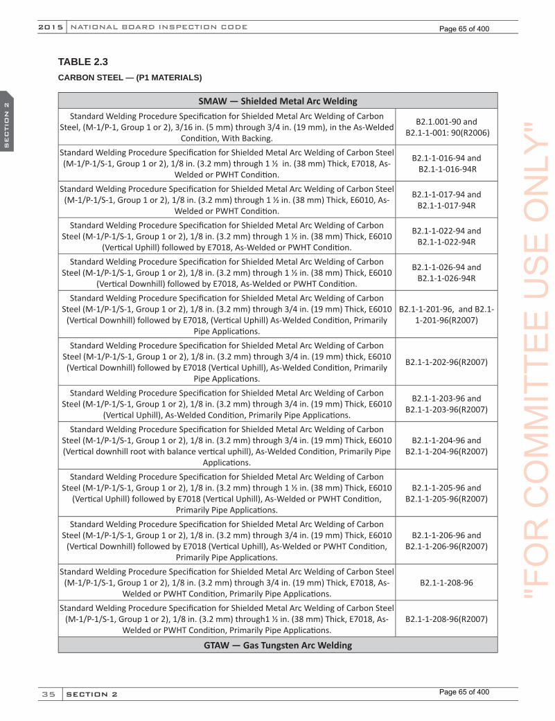
35
NATIONAL BOARD INSPECTION CODE2015
SECTION 2
SEC
TIO
N 2
TABLE 2.3CARBON STEEL — (P1 MATERIALS)
SMAW — Shielded Metal Arc WeldingStandard Welding Procedure Specification for Shielded Metal Arc Welding of Carbon
Steel, (M-1/P-1, Group 1 or 2), 3/16 in. (5 mm) through 3/4 in. (19 mm), in the As-Welded Condition, With Backing.
B2.1.001-90 and B2.1-1-001: 90(R2006)
Standard Welding Procedure Specification for Shielded Metal Arc Welding of Carbon Steel (M-1/P-1/S-1, Group 1 or 2), 1/8 in. (3.2 mm) through 1 ½ in. (38 mm) Thick, E7018, As-
Welded or PWHT Condition.
B2.1-1-016-94 and B2.1-1-016-94R
Standard Welding Procedure Specification for Shielded Metal Arc Welding of Carbon Steel (M-1/P-1/S-1, Group 1 or 2), 1/8 in. (3.2 mm) through 1 ½ in. (38 mm) Thick, E6010, As-
Welded or PWHT Condition.
B2.1-1-017-94 and B2.1-1-017-94R
Standard Welding Procedure Specification for Shielded Metal Arc Welding of Carbon Steel (M-1/P-1/S-1, Group 1 or 2), 1/8 in. (3.2 mm) through 1 ½ in. (38 mm) Thick, E6010
(Vertical Uphill) followed by E7018, As-Welded or PWHT Condition.
B2.1-1-022-94 and B2.1-1-022-94R
Standard Welding Procedure Specification for Shielded Metal Arc Welding of Carbon Steel (M-1/P-1/S-1, Group 1 or 2), 1/8 in. (3.2 mm) through 1 ½ in. (38 mm) Thick, E6010
(Vertical Downhill) followed by E7018, As-Welded or PWHT Condition.
B2.1-1-026-94 and B2.1-1-026-94R
Standard Welding Procedure Specification for Shielded Metal Arc Welding of Carbon Steel (M-1/P-1/S-1, Group 1 or 2), 1/8 in. (3.2 mm) through 3/4 in. (19 mm) Thick, E6010
(Vertical Downhill) followed by E7018, (Vertical Uphill) As-Welded Condition, Primarily Pipe Applications.
B2.1-1-201-96, and B2.1-1-201-96(R2007)
Standard Welding Procedure Specification for Shielded Metal Arc Welding of Carbon Steel (M-1/P-1/S-1, Group 1 or 2), 1/8 in. (3.2 mm) through 3/4 in. (19 mm) thick, E6010 (Vertical Downhill) followed by E7018 (Vertical Uphill), As-Welded Condition, Primarily
Pipe Applications.
B2.1-1-202-96(R2007)
Standard Welding Procedure Specification for Shielded Metal Arc Welding of Carbon Steel (M-1/P-1/S-1, Group 1 or 2), 1/8 in. (3.2 mm) through 3/4 in. (19 mm) Thick, E6010
(Vertical Uphill), As-Welded Condition, Primarily Pipe Applications.
B2.1-1-203-96 and B2.1-1-203-96(R2007)
Standard Welding Procedure Specification for Shielded Metal Arc Welding of Carbon Steel (M-1/P-1/S-1, Group 1 or 2), 1/8 in. (3.2 mm) through 3/4 in. (19 mm) Thick, E6010 (Vertical downhill root with balance vertical uphill), As-Welded Condition, Primarily Pipe
Applications.
B2.1-1-204-96 and B2.1-1-204-96(R2007)
Standard Welding Procedure Specification for Shielded Metal Arc Welding of Carbon Steel (M-1/P-1/S-1, Group 1 or 2), 1/8 in. (3.2 mm) through 1 ½ in. (38 mm) Thick, E6010
(Vertical Uphill) followed by E7018 (Vertical Uphill), As-Welded or PWHT Condition, Primarily Pipe Applications.
B2.1-1-205-96 and B2.1-1-205-96(R2007)
Standard Welding Procedure Specification for Shielded Metal Arc Welding of Carbon Steel (M-1/P-1/S-1, Group 1 or 2), 1/8 in. (3.2 mm) through 3/4 in. (19 mm) Thick, E6010
(Vertical Downhill) followed by E7018 (Vertical Uphill), As-Welded or PWHT Condition, Primarily Pipe Applications.
B2.1-1-206-96 and B2.1-1-206-96(R2007)
Standard Welding Procedure Specification for Shielded Metal Arc Welding of Carbon Steel (M-1/P-1/S-1, Group 1 or 2), 1/8 in. (3.2 mm) through 3/4 in. (19 mm) Thick, E7018, As-
Welded or PWHT Condition, Primarily Pipe Applications.B2.1-1-208-96
Standard Welding Procedure Specification for Shielded Metal Arc Welding of Carbon Steel (M-1/P-1/S-1, Group 1 or 2), 1/8 in. (3.2 mm) through1 ½ in. (38 mm) Thick, E7018, As-
Welded or PWHT Condition, Primarily Pipe Applications.B2.1-1-208-96(R2007)
GTAW — Gas Tungsten Arc Welding
"FO
RC
OM
MIT
TEE
US
EO
NLY
"
Page 65 of 400
Page 65 of 400
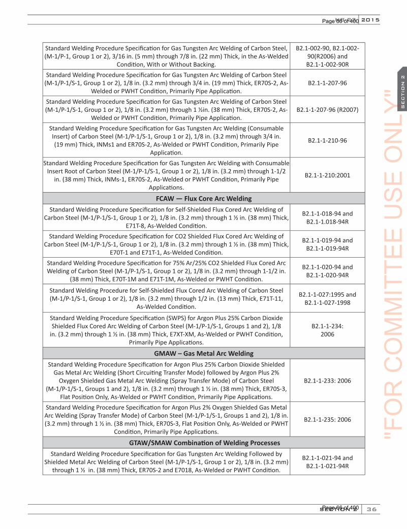
36
2015
SECTION 2
SEC
TIO
N 2
NB-23
Standard Welding Procedure Specification for Gas Tungsten Arc Welding of Carbon Steel, (M-1/P-1, Group 1 or 2), 3/16 in. (5 mm) through 7/8 in. (22 mm) Thick, in the As-Welded
Condition, With or Without Backing.
B2.1-002-90, B2.1-002-90(R2006) and B2.1-1-002-90R
Standard Welding Procedure Specification for Gas Tungsten Arc Welding of Carbon Steel (M-1/P-1/S-1, Group 1 or 2), 1/8 in. (3.2 mm) through 3/4 in. (19 mm) Thick, ER70S-2, As-
Welded or PWHT Condition, Primarily Pipe Application.B2.1-1-207-96
Standard Welding Procedure Specification for Gas Tungsten Arc Welding of Carbon Steel (M-1/P-1/S-1, Group 1 or 2), 1/8 in. (3.2 mm) through 1 ½in. (38 mm) Thick, ER70S-2, As-
Welded or PWHT Condition, Primarily Pipe Application.B2.1-1-207-96 (R2007)
Standard Welding Procedure Specification for Gas Tungsten Arc Welding (Consumable Insert) of Carbon Steel (M-1/P-1/S-1, Group 1 or 2), 1/8 in. (3.2 mm) through 3/4 in. (19 mm) Thick, INMs1 and ER70S-2, As-Welded or PWHT Condition, Primarily Pipe
Application.
B2.1-1-210-96
Standard Welding Procedure Specification for Gas Tungsten Arc Welding with Consumable Insert Root of Carbon Steel (M-1/P-1/S-1, Group 1 or 2), 1/8 in. (3.2 mm) through 1-1/2
in. (38 mm) Thick, INMs-1, ER70S-2, As-Welded or PWHT Condition, Primarily Pipe Applications.
B2.1-1-210:2001
FCAW — Flux Core Arc WeldingStandard Welding Procedure Specification for Self-Shielded Flux Cored Arc Welding of
Carbon Steel (M-1/P-1/S-1, Group 1 or 2), 1/8 in. (3.2 mm) through 1 ½ in. (38 mm) Thick, E71T-8, As-Welded Condition.
B2.1-1-018-94 and B2.1-1.018-94R
Standard Welding Procedure Specification for CO2 Shielded Flux Cored Arc Welding of Carbon Steel (M-1/P-1/S-1, Group 1 or 2), 1/8 in. (3.2 mm) through 1 ½ in. (38 mm) Thick,
E70T-1 and E71T-1, As-Welded Condition.
B2.1-1-019-94 andB2.1-1-019-94R
Standard Welding Procedure Specification for 75% Ar/25% CO2 Shielded Flux Cored Arc Welding of Carbon Steel (M-1/P-1/S-1, Group 1 or 2), 1/8 in. (3.2 mm) through 1-1/2 in.
(38 mm) Thick, E70T-1M and E71T-1M, As-Welded or PWHT Condition.
B2.1-1-020-94 and B2.1-1-020-94R
Standard Welding Procedure for Self-Shielded Flux Cored Arc Welding of Carbon Steel (M-1/P-1/S-1, Group 1 or 2), 1/8 in. (3.2 mm) through 1/2 in. (13 mm) Thick, E71T-11,
As-Welded Condition.
B2.1-1-027:1995 and B2.1-1-027-1998
Standard Welding Procedure Specification (SWPS) for Argon Plus 25% Carbon Dioxide Shielded Flux Cored Arc Welding of Carbon Steel (M-1/P-1/S-1, Groups 1 and 2), 1/8
in. (3.2 mm) through 1 ½ in. (38 mm) Thick, E7XT-XM, As-Welded or PWHT Condition, Primarily Pipe Applications.
B2.1-1-234: 2006
GMAW – Gas Metal Arc WeldingStandard Welding Procedure Specification for Argon Plus 25% Carbon Dioxide Shielded
Gas Metal Arc Welding (Short Circuiting Transfer Mode) followed by Argon Plus 2% Oxygen Shielded Gas Metal Arc Welding (Spray Transfer Mode) of Carbon Steel
(M-1/P-1/S-1, Groups 1 and 2), 1/8 in. (3.2 mm) through 1 ½ in. (38 mm) Thick, ER70S-3, Flat Position Only, As-Welded or PWHT Condition, Primarily Pipe Applications.
B2.1-1-233: 2006
Standard Welding Procedure Specification for Argon Plus 2% Oxygen Shielded Gas Metal Arc Welding (Spray Transfer Mode) of Carbon Steel (M-1/P-1/S-1, Groups 1 and 2), 1/8 in. (3.2 mm) through 1 ½ in. (38 mm) Thick, ER70S-3, Flat Position Only, As-Welded or PWHT
Condition, Primarily Pipe Applications.
B2.1-1-235: 2006
GTAW/SMAW Combination of Welding ProcessesStandard Welding Procedure Specification for Gas Tungsten Arc Welding Followed by
Shielded Metal Arc Welding of Carbon Steel (M-1/P-1/S-1, Group 1 or 2), 1/8 in. (3.2 mm) through 1 ½ in. (38 mm) Thick, ER70S-2 and E7018, As-Welded or PWHT Condition.
B2.1-1-021-94 and B2.1-1-021-94R
"FO
RC
OM
MIT
TEE
US
EO
NLY
"O
NLY
"O
NLY
"S
EC
TIO
N 2
ON
LY"
SEC
TIO
N 2
Page 66 of 400
Page 66 of 400
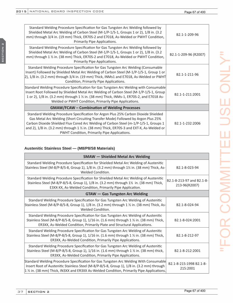
37
NATIONAL BOARD INSPECTION CODE2015
SECTION 2
SEC
TIO
N 2
Standard Welding Procedure Specification for Gas Tungsten Arc Welding followed by Shielded Metal Arc Welding of Carbon Steel (M-1/P-1/S-1, Groups 1 or 2), 1/8 in. (3.2
mm) through 3/4 in. (19 mm) Thick, ER70S-2 and E7018, As-Welded or PWHT Condition, Primarily Pipe Applications.
B2.1-1-209-96
Standard Welding Procedure Specification for Gas Tungsten Arc Welding followed by Shielded Metal Arc Welding of Carbon Steel (M-1/P-1/S-1, Groups 1 or 2), 1/8 in. (3.2
mm) through 1 ½ in. (38 mm) Thick, ER70S-2 and E7018, As-Welded or PWHT Condition, Primarily Pipe Applications.
B2.1-1-209-96 (R2007)
Standard Welding Procedure Specification for Gas Tungsten Arc Welding (Consumable Insert) Followed by Shielded Metal Arc Welding of Carbon Steel (M-1/P-1/S-1, Group 1 or
2), 1/8 in. (3.2 mm) through 3/4 in. (19 mm) Thick, INMs1 and E7018, As-Welded or PWHT Condition, Primarily Pipe Applications.
B2.1-1-211-96
Standard Welding Procedure Specification for Gas Tungsten Arc Welding with Consumable Insert Root Followed by Shielded Metal Arc Welding of Carbon Steel (M-1/P-1/S-1, Group 1 or 2), 1/8 in. (3.2 mm) through 1 ½ in. (38 mm) Thick, INMs-1, ER70S-2, and E7018 As-
Welded or PWHT Condition, Primarily Pipe Applications.
B2.1-1-211:2001
GMAW/FCAW – Combination of Welding ProcessesStandard Welding Procedure Specification for Argon Plus 25% Carbon Dioxide Shielded
Gas Metal Arc Welding (Short Circuiting Transfer Mode) Followed by Argon Plus 25% Carbon Dioxide Shielded Flux Cored Arc Welding of Carbon Steel (m-1/P-1/S-1, Groups 1 and 2), 1/8 in. (3.2 mm) through 1 ½ in. (38 mm) Thick, ER70S-3 and EXT-X, As-Welded or
PWHT Condition, Primarily Pipe Applications.
B2.1-1-232:2006
Austenitic Stainless Steel — (M8/P8/S8 Materials)
SMAW — Shielded Metal Arc WeldingStandard Welding Procedure Specification for Shielded Metal Arc Welding of Austenitic
Stainless Steel (M-8/P-8/S-8, Group 1), 1/8 in. (3.2 mm) through 1½ in. (38 mm) Thick, As-Welded Condition.
B2.1-8-023-94
Standard Welding Procedure Specification for Shielded Metal Arc Welding of Austenitic Stainless Steel (M-8/P-8/S-8, Group 1), 1/8 in. (3.2 mm) through 1½ in. (38 mm) Thick,
E3XX-XX, As-Welded Condition, Primarily Pipe Application.
B2.1-8-213-97 and B2.1-8-213-96(R2007)
GTAW — Gas Tungsten Arc WeldingStandard Welding Procedure Specification for Gas Tungsten Arc Welding of Austenitic
Stainless Steel (M-8/P-8/S-8, Group 1), 1/8 in. (3.2 mm) through 1 ½ in. (38 mm) Thick, As-Welded Condition.
B2.1-8-024-94
Standard Welding Procedure Specification for Gas Tungsten Arc Welding of Austenitic Stainless Steel (M-8/P-8/S-8, Group 1), 1/16 in. (1.6 mm) through 1 ½ in. (38 mm) Thick,
ER3XX, As-Welded Condition, Primarily Plate and Structural Applications.B2.1-8-024:2001
Standard Welding Procedure Specification for Gas Tungsten Arc Welding of Austenitic Stainless Steel (M-8/P-8/S-8, Group 1), 1/16 in. (1.6 mm) through 1 ½ in. (38 mm) Thick,
ER3XX, As-Welded Condition, Primarily Pipe Applications.B2.1-8-212-97
Standard Welding Procedure Specification for Gas Tungsten Arc Welding of Austenitic Stainless Steel (M-8/P-8/S-8, Group 1), 1/16 in. (1.6 mm) through 1 ½ in. (38 mm) thick,
ER3XX, As-Welded Condition, Primarily Pipe Applications.B2.1-8-212:2001
Standard Welding Procedure Specification for Gas Tungsten Arc Welding With Consumable Insert Root of Austenitic Stainless Steel (M-8/P-8/S-8, Group 1), 1/8 in. (3.2 mm) through
1 ½ in. (38 mm) Thick, IN3XX and ER3XX As-Welded Condition, Primarily Pipe Applications.
B2.1-8-215:1998 B2.1-8-215:2001
"FO
RC
OM
MIT
TEE
US
EO
NLY
"
Page 67 of 400
Page 67 of 400

38
2015
SECTION 2
SEC
TIO
N 2
NB-23
Combination Processes GTAW/SMAWStandard Welding Procedure Specification for Gas Tungsten Arc Welding followed by
Shielded Metal Arc Welding of Austenitic Stainless Steel (M-8/P-8/S-8, Group 1), 1/8 in. (3.2 mm) through 1 ½ in. (38 mm) Thick, As-Welded Condition.
B2.1-8-025-94
Standard Welding Procedure Specification for Gas Tungsten Arc Welding followed by Shielded Metal Arc Welding of Austenitic Stainless Steel (M-8/P-8/S-8, Group 1), 1/8
in. (3.2 mm) through 1 ½ in. (38 mm) Thick, ER3XX and E3XX-XX, As-Welded Condition, Primarily Plate and Structural Applications.
B2.1-8-025:2001
Standard Welding Procedure Specification for Gas Tungsten Arc Welding Followed by Shielded Metal Arc Welding of Austenitic Stainless Steel (M-8/P-8/S-8, Group 1), 1/8
in. (3.2 mm) through 1 ½ in. (38 mm) Thick, ER3XX and E3XX-XX, As-Welded Condition, Primarily Pipe Applications.
B2.1-8-214-97
Standard Welding Procedure Specification for Gas Tungsten Arc Welding Followed by Shielded Metal Arc Welding of Austenitic Stainless Steel (M-8/P-8/S-8, Group 1), 1/8
in. (3.2 mm) through 1 ½ in. (38 mm) Thick, ER3XX and E3XX-XX, As-Welded Condition, Primarily Pipe Applications.
B2.1-8-214:2001
Standard Welding Procedure Specification for Gas Tungsten Arc Welding With Consumable Insert Followed by Shielded Metal Arc Welding of Austenitic Stainless Steel (M-8/P-8/S-8, Group 1), 1/8 in. (3.2 mm) through 1 ½ in. (38 mm) thick, IN3XX, ER3XX, and E3XX-XX As-
Welded Condition, Primarily Pipe Application.
B2.1-8-216-1998
Standard Welding Procedure Specification for Gas Tungsten Arc Welding with Consumable Insert Root followed by Shielded Metal Arc Welding of Austenitic Stainless Steel (M-8/P-
8/S-8, Group 1), 1/8 in. (3.2 mm) through 1 ½ in. (38 mm) Thick, IN3XX, ER3XX, and E3XX-XX As-Welded Condition, Primarily Pipe Applications.
B2.1-8-216:2001
Combination of Carbon Steel (P-1 Material) To Austenitic Stainless Steel (P-8 Material)
SMAW — Shielded Metal Arc WeldingStandard Welding Procedure Specifications for Shielded Metal Arc Welding of Carbon Steel (M-1/P-1/S-1, Groups 1 or 2) to Austenitic Stainless Steel (M-8/P-8/S-8, Group
1), 1/8 in. (3.2 mm) through 1 ½ in. (38 mm) Thick, E309(L)-15, -16, or -17, As-Welded Condition, Primarily Pipe Applications.
B2.1-1/8-228:2002
GTAW — Gas Tungsten Arc WeldingStandard Welding Procedure Specification for Gas Tungsten Arc Welding of Carbon Steel (M-1/P-1/S-1, Groups 1 or 2) to Austenitic Stainless Steel (M-8/P-8/S-8, Group
1), 1/16 in. (1.6 mm) through 1 ½ in. (38 mm) Thick, ER309(L), As-Welded Condition, Primarily Pipe Applications.
B2.1-1/8-227:2002
Standard Welding Procedure Specifications for Gas Tungsten Arc Welding with Consumable Insert Root of Carbon Steel (M-1/P-1/S-1, Groups 1 or 2) to Austenitic
Stainless Steel (M-8/P-8/S-8, Group 1), 1/16 in. (1.6 mm) through 1½ in. (38 mm) Thick, IN309 and ER309(L), As-Welded Condition, Primarily Pipe Applications.
B2.1-1/8-230:2002
GTAW/SMAW Combination of Welding ProcessesStandard Welding Procedure Specifications for Gas Tungsten Arc Welding followed by Shielded Metal Arc Welding of Carbon Steel (M-1/P-1/S-1,Groups 1 or 2) to Austenitic Stainless Steel (M-8/P-8/S-8, Group 1), 1/8 in. (3.2 mm) through 1½ in. (38 mm) Thick,
ER309(L) and E309(L)-15, -16, or -17, As-Welded Condition, Primarily Pipe Applications.
B2.1-1/8-229:2002 "FO
RC
OM
MIT
TEE
US
EO
NLY
"O
NLY
"O
NLY
"S
EC
TIO
N 2
ON
LY"
SEC
TIO
N 2
Page 68 of 400
Page 68 of 400
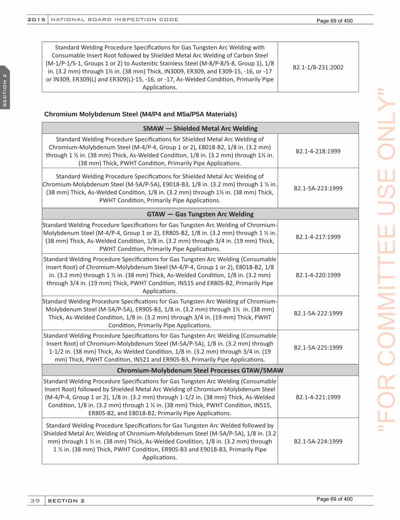
39
NATIONAL BOARD INSPECTION CODE2015
SECTION 2
SEC
TIO
N 2
Standard Welding Procedure Specifications for Gas Tungsten Arc Welding with Consumable Insert Root followed by Shielded Metal Arc Welding of Carbon Steel
(M-1/P-1/S-1, Groups 1 or 2) to Austenitic Stainless Steel (M-8/P-8/S-8, Group 1), 1/8 in. (3.2 mm) through 1½ in. (38 mm) Thick, IN3009, ER309, and E309-15, -16, or -17
or IN309, ER309(L) and ER309(L)-15, -16, or -17, As-Welded Condition, Primarily Pipe Applications.
B2.1-1/8-231:2002
Chromium Molybdenum Steel (M4/P4 and M5a/P5A Materials)
SMAW — Shielded Metal Arc WeldingStandard Welding Procedure Specifications for Shielded Metal Arc Welding of
Chromium-Molybdenum Steel (M-4/P-4, Group 1 or 2), E8018-B2, 1/8 in. (3.2 mm) through 1 ½ in. (38 mm) Thick, As-Welded Condition, 1/8 in. (3.2 mm) through 1½ in.
(38 mm) Thick, PWHT Condition, Primarily Pipe Applications.
B2.1-4-218:1999
Standard Welding Procedure Specifications for Shielded Metal Arc Welding of Chromium-Molybdenum Steel (M-5A/P-5A), E9018-B3, 1/8 in. (3.2 mm) through 1 ½ in.
(38 mm) Thick, As-Welded Condition, 1/8 in. (3.2 mm) through 1½ in. (38 mm) Thick, PWHT Condition, Primarily Pipe Applications.
B2.1-5A-223:1999
GTAW — Gas Tungsten Arc WeldingStandard Welding Procedure Specifications for Gas Tungsten Arc Welding of Chromium-Molybdenum Steel (M-4/P-4, Group 1 or 2), ER80S-B2, 1/8 in. (3.2 mm) through 1 ½ in. (38 mm) Thick, As-Welded Condition, 1/8 in. (3.2 mm) through 3/4 in. (19 mm) Thick,
PWHT Condition, Primarily Pipe Applications.
B2.1-4-217:1999
Standard Welding Procedure Specifications for Gas Tungsten Arc Welding (Consumable Insert Root) of Chromium-Molybdenum Steel (M-4/P-4, Group 1 or 2), E8018-B2, 1/8
in. (3.2 mm) through 1 ½ in. (38 mm) Thick, As-Welded Condition, 1/8 in. (3.2 mm) through 3/4 in. (19 mm) Thick, PWHT Condition, IN515 and ER80S-B2, Primarily Pipe
Applications.
B2.1-4-220:1999
Standard Welding Procedure Specifications for Gas Tungsten Arc Welding of Chromium-Molybdenum Steel (M-5A/P-5A), ER90S-B3, 1/8 in. (3.2 mm) through 1½ in. (38 mm) Thick, As-Welded Condition, 1/8 in. (3.2 mm) through 3/4 in. (19 mm) Thick, PWHT
Condition, Primarily Pipe Applications.
B2.1-5A-222:1999
Standard Welding Procedure Specifications for Gas Tungsten Arc Welding (Consumable Insert Root) of Chromium-Molybdenum Steel (M-5A/P-5A), 1/8 in. (3.2 mm) through 1-1/2 in. (38 mm) Thick, As-Welded Condition, 1/8 in. (3.2 mm) through 3/4 in. (19
mm) Thick, PWHT Condition, IN521 and ER90S-B3, Primarily Pipe Applications.
B2.1-5A-225:1999
Chromium-Molybdenum Steel Processes GTAW/SMAWStandard Welding Procedure Specifications for Gas Tungsten Arc Welding (Consumable Insert Root) followed by Shielded Metal Arc Welding of Chromium-Molybdenum Steel (M-4/P-4, Group 1 or 2), 1/8 in. (3.2 mm) through 1-1/2 in. (38 mm) Thick, As-Welded
Condition, 1/8 in. (3.2 mm) through 1 ½ in. (38 mm) Thick, PWHT Condition, IN515, ER80S-B2, and E8018-B2, Primarily Pipe Applications.
B2.1-4-221:1999
Standard Welding Procedure Specifications for Gas Tungsten Arc Welded followed by Shielded Metal Arc Welding of Chromium-Molybdenum Steel (M-5A/P-5A), 1/8 in. (3.2
mm) through 1 ½ in. (38 mm) Thick, As-Welded Condition, 1/8 in. (3.2 mm) through 1 ½ in. (38 mm) Thick, PWHT Condition, ER90S-B3 and E9018-B3, Primarily Pipe
Applications.
B2.1-5A-224:1999
"FO
RC
OM
MIT
TEE
US
EO
NLY
"
Page 69 of 400
Page 69 of 400
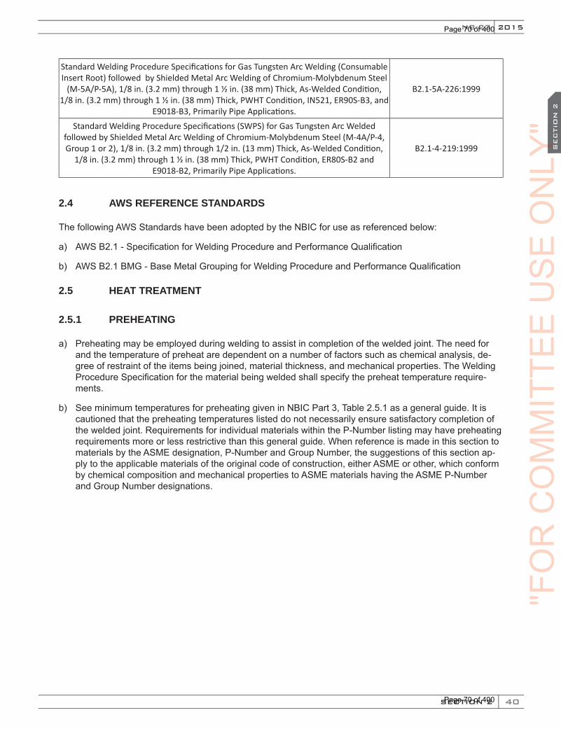
40
2015
SECTION 2
SEC
TIO
N 2
NB-23
Standard Welding Procedure Specifications for Gas Tungsten Arc Welding (Consumable Insert Root) followed by Shielded Metal Arc Welding of Chromium-Molybdenum Steel
(M-5A/P-5A), 1/8 in. (3.2 mm) through 1 ½ in. (38 mm) Thick, As-Welded Condition, 1/8 in. (3.2 mm) through 1 ½ in. (38 mm) Thick, PWHT Condition, IN521, ER90S-B3, and
E9018-B3, Primarily Pipe Applications.
B2.1-5A-226:1999
Standard Welding Procedure Specifications (SWPS) for Gas Tungsten Arc Welded followed by Shielded Metal Arc Welding of Chromium-Molybdenum Steel (M-4A/P-4, Group 1 or 2), 1/8 in. (3.2 mm) through 1/2 in. (13 mm) Thick, As-Welded Condition,
1/8 in. (3.2 mm) through 1 ½ in. (38 mm) Thick, PWHT Condition, ER80S-B2 and E9018-B2, Primarily Pipe Applications.
B2.1-4-219:1999
2.4 AWS REFERENCE STANDARDS
The following AWS Standards have been adopted by the NBIC for use as referenced below:
a) AWS B2.1 - Specification for Welding Procedure and Performance Qualification
b) AWS B2.1 BMG - Base Metal Grouping for Welding Procedure and Performance Qualification
2.5 HEAT TREATMENT
2.5.1 PREHEATING
a) Preheating may be employed during welding to assist in completion of the welded joint. The need for and the temperature of preheat are dependent on a number of factors such as chemical analysis, de-gree of restraint of the items being joined, material thickness, and mechanical properties. The Welding Procedure Specification for the material being welded shall specify the preheat temperature require-ments.
b) See minimum temperatures for preheating given in NBIC Part 3, Table 2.5.1 as a general guide. It is cautioned that the preheating temperatures listed do not necessarily ensure satisfactory completion of the welded joint. Requirements for individual materials within the P-Number listing may have preheating requirements more or less restrictive than this general guide. When reference is made in this section to materials by the ASME designation, P-Number and Group Number, the suggestions of this section ap-ply to the applicable materials of the original code of construction, either ASME or other, which conform by chemical composition and mechanical properties to ASME materials having the ASME P-Number and Group Number designations.
"FO
RC
OM
MIT
TEE
US
EO
NLY
"O
NLY
"O
NLY
"S
EC
TIO
N 2
ON
LY"
SEC
TIO
N 2
Page 70 of 400
Page 70 of 400
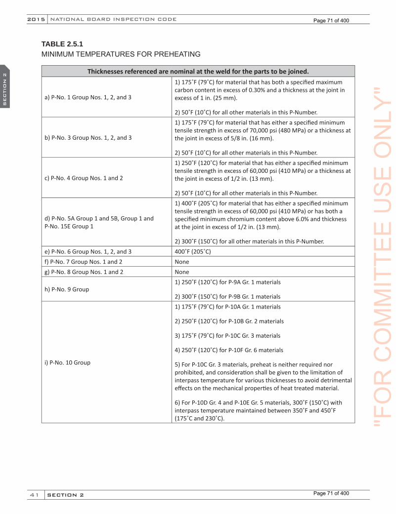
41
NATIONAL BOARD INSPECTION CODE2015
SECTION 2
SEC
TIO
N 2
TABLE 2.5.1MINIMUM TEMPERATURES FOR PREHEATING
Thicknesses referenced are nominal at the weld for the parts to be joined.
a) P-No. 1 Group Nos. 1, 2, and 3
1) 175˚F (79˚C) for material that has both a specified maximum carbon content in excess of 0.30% and a thickness at the joint in excess of 1 in. (25 mm).
2) 50˚F (10˚C) for all other materials in this P-Number.
b) P-No. 3 Group Nos. 1, 2, and 3
1) 175˚F (79˚C) for material that has either a specified minimum tensile strength in excess of 70,000 psi (480 MPa) or a thickness at the joint in excess of 5/8 in. (16 mm).
2) 50˚F (10˚C) for all other materials in this P-Number.
c) P-No. 4 Group Nos. 1 and 2
1) 250˚F (120˚C) for material that has either a specified minimum tensile strength in excess of 60,000 psi (410 MPa) or a thickness at the joint in excess of 1/2 in. (13 mm).
2) 50˚F (10˚C) for all other materials in this P-Number.
d) P-No. 5A Group 1 and 5B, Group 1 and P-No. 15E Group 1
1) 400˚F (205˚C) for material that has either a specified minimum tensile strength in excess of 60,000 psi (410 MPa) or has both a specified minimum chromium content above 6.0% and thickness at the joint in excess of 1/2 in. (13 mm).
2) 300˚F (150˚C) for all other materials in this P-Number.e) P-No. 6 Group Nos. 1, 2, and 3 400˚F (205˚C)f) P-No. 7 Group Nos. 1 and 2 Noneg) P-No. 8 Group Nos. 1 and 2 None
h) P-No. 9 Group1) 250˚F (120˚C) for P-9A Gr. 1 materials
2) 300˚F (150˚C) for P-9B Gr. 1 materials
i) P-No. 10 Group
1) 175˚F (79˚C) for P-10A Gr. 1 materials
2) 250˚F (120˚C) for P-10B Gr. 2 materials
3) 175˚F (79˚C) for P-10C Gr. 3 materials
4) 250˚F (120˚C) for P-10F Gr. 6 materials
5) For P-10C Gr. 3 materials, preheat is neither required nor prohibited, and consideration shall be given to the limitation of interpass temperature for various thicknesses to avoid detrimental effects on the mechanical properties of heat treated material.
6) For P-10D Gr. 4 and P-10E Gr. 5 materials, 300˚F (150˚C) with interpass temperature maintained between 350˚F and 450˚F (175˚C and 230˚C). "F
OR
CO
MM
ITTE
EU
SE
ON
LY"
Page 71 of 400
Page 71 of 400

42
2015
SECTION 2
SEC
TIO
N 2
NB-23
j) P-No. 11 Group
1) P-11A Group Group 1 - None (Note 1) Group 2 - Same as for P-No. 5 (Note 1) Group 3 - Same as for P-No. 5 (Note 1) Group 4 - 250˚F (120˚C)
2) P-11B Group Group 1 - Same as for P-No. 3 (Note 1) Group 2 - Same as for P-No. 3 (Note 1) Group 3 - Same as for P-No. 3 (Note 1) Group 4 - Same as for P-No. 3 (Note 1) Group 5 - Same as for P-No. 3 (Note 1) Group 6 - Same as for P-No. 5 (Note 1) Group 7 - Same as for P-No. 5 (Note 1)
Note 1: Consideration shall be given to the limitation of interpass temperature for various thicknesses to avoid detrimental effects on the mechanical properties of heat treated materials.
2.5.2 POSTWELD HEAT TREATMENT (PWHT)
a) Postweld heat treatment shall be performed as required by the original code of construction, the construction standard or code selected in accordance with a written procedure. The procedure shall contain the parameters for postweld heat treatment.
b) Postweld heat treatment shall be performed by heating either the entire item or a circumferential band around the item. When heating a circumferential band, the heat treatment procedure shall specify the soak band (SB) width, the heated band (HB) width, the gradient control band (GCB) width, the location of thermocouples and method of attachment of thermocouples in addition to the heating rate, holding time, temperature and cooling rate. Figures S2.5.2-a and S2.5.2-b show these bands. AWS 010.10,Recommended Practices for Local Heating of Welds in Piping and Tubing may be referred to for further information.
c) When it is impractical or detrimental to Postweld Heat Treat (PWHT) the entire item or band around the item, the following local PWHT method may be performed on spherical or cylindrical pressure-retaining items using the time and temperature parameters in the original code of construction and in accordance with a written procedure acceptable to the Inspector and, when required, by the Jurisdiction.
1) Heat a local area around the nozzle, welded attachment, or repair area such that the area is brought up uniformly to the required PWHT temperature. The application of local PWHT should be performed with controlled heating methods, such as induction or electric resistance heaters, and employing thermocouples to monitor PWHT temperature. The Soak Band (SB) shall extend tan-gentially and radially from the edge of the nozzle wall, or attachment weld or repair area equally by a minimum distance as defined by the thickness of the shell, t or 2 in. (50 mm), whichever is less. See Figure 2.5.2-b.
Soak Band (SB) — this is the region on the spherical or cylindrical shell that will be heated uniformly to the required PWHT temperature. This band encompasses a circular region in the tangential and radial directions starting from the edge of a welded nozzle, or repair area or welded attachment that will be subjected to PWHT.
2) The length of the Heating Band (HB) shall consist of the SB distance plus 4 𝑅𝑅 ∗ 𝑡𝑡 . In no case shall the distance of the HB that extends beyond the edge of the nozzle weld, attachment weld or repair area be less than 5 𝑅𝑅 ∗ 𝑡𝑡 .
"FO
RC
OM
MIT
TEE
US
EO
NLY
"O
NLY
"O
NLY
"S
EC
TIO
N 2
ON
LY"
SEC
TIO
N 2
Page 72 of 400
Page 72 of 400
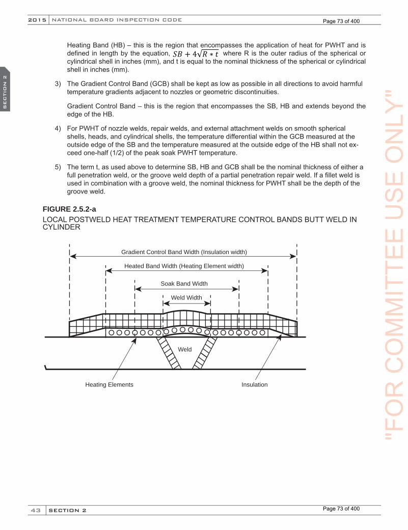
43
NATIONAL BOARD INSPECTION CODE2015
SECTION 2
SEC
TIO
N 2
Heating Band (HB) – this is the region that encompasses the application of heat for PWHT and is defined in length by the equation, 𝑆𝑆𝑆𝑆 + 4 𝑅𝑅 ∗ 𝑡𝑡 where R is the outer radius of the spherical or cylindrical shell in inches (mm), and t is equal to the nominal thickness of the spherical or cylindrical shell in inches (mm).
3) The Gradient Control Band (GCB) shall be kept as low as possible in all directions to avoid harmful temperature gradients adjacent to nozzles or geometric discontinuities.
Gradient Control Band – this is the region that encompasses the SB, HB and extends beyond the edge of the HB.
4) For PWHT of nozzle welds, repair welds, and external attachment welds on smooth spherical shells, heads, and cylindrical shells, the temperature differential within the GCB measured at the outside edge of the SB and the temperature measured at the outside edge of the HB shall not ex-ceed one-half (1/2) of the peak soak PWHT temperature.
5) The term t, as used above to determine SB, HB and GCB shall be the nominal thickness of either a full penetration weld, or the groove weld depth of a partial penetration repair weld. If a fillet weld is used in combination with a groove weld, the nominal thickness for PWHT shall be the depth of the groove weld.
FIGURE 2.5.2-aLOCAL POSTWELD HEAT TREATMENT TEMPERATURE CONTROL BANDS BUTT WELD IN CYLINDER
Gradient Control Band Width (Insulation width)
Heated Band Width (Heating Element width)
Soak Band Width
Weld Width
Weld
Heating Elements Insulation
"FO
RC
OM
MIT
TEE
US
EO
NLY
"
Page 73 of 400
Page 73 of 400

44
2015
SECTION 2
SEC
TIO
N 2
NB-23
FIGURE 2.5.2-bLOCAL POSTWELD HEAT TREATMENT TEMPERATURE CONTROL BANDS NOZZLE WELD OR ATTACHMENT TANGENTIAL DIRECTION HEATING BANDS
Heated Band Width (Heating Element Width)
Gradient Band Width (Insulation Width)
Soak Band Width
Nozzle Diameter
2.5.3 ALTERNATIVE WELDING METHODS WITHOUT POSTWELD HEAT TREATMENT
a) Under certain conditions, postweld heat treatment, in accordance with the original code of construction, may be inadvisable or impractical. In such instances, the following alternative methods may be used.
b) Competent technical advice shall be obtained from the manufacturer of the pressure-retaining item or from another qualified source, such advice being especially necessary if the alternative is to be used in highly stressed areas, if service conditions are conducive to stress corrosion cracking, if materials are subject to hydrogen embrittlement, or are operating at temperatures in the creep range, or if the alter-native is being considered for “on-stream” repairs or “hot tapping” on piping systems. Selection of the welding method used shall be based on the rules of the original code of construction together with the above mentioned advice concerning the adequacy of the weld in the as-welded condition at operating and pressure test conditions.
"FO
RC
OM
MIT
TEE
US
EO
NLY
"O
NLY
"O
NLY
"S
EC
TIO
N 2
ON
LY"
SEC
TIO
N 2
Page 74 of 400
Page 74 of 400

45
NATIONAL BOARD INSPECTION CODE2015
SECTION 2
SEC
TIO
N 2
c) When reference is made in this section to materials by the ASME designation, P-Number and Group Number, the requirements of this section apply to the applicable materials of the original code of con-struction, either ASME or other, which conform by chemical composition and mechanical properties to the ASME P-Number and Group Number designations.
d) The detailed welding methods listed in the following subsections may be used as an alternative to post-weld heat treatment (PWHT). NBIC Part 3, 2.5.3.1 is a method in which the welding procedure requires an elevation of the preheat temperature. In contrast, NBIC Part 3, 2.5.3.2 through 2.5.3.6, are methods in which the welding procedure requires the use of a temper-bead welding technique. In 2.5.3.5 is a method in which the welding procedure used for joining dissimilar materials requires either an elevation of the preheat temperature or a temper-bead welding technique, depending on the chemical composi-tion of the base metal that is joined to an austenitic steel. Temper-bead welding procedure nomencla-ture is defined in Section IX of the ASME Boiler and Pressure Vessel Code. Typically, this technique minimizes heat input of the initial beads, thus limiting heat beyond the weld heat-affected zone (HAZ) of the base metal. Heat input shall be increased for successive beads in accordance with the rules of QW-290 for temper bead welding in ASME Section IX. The Welding Procedure and Welder Performance Qualifications shall, in all cases, be in accordance with the requirements of the latest Edition of Section IX of the ASME Boiler and Pressure Vessel Code.
e) Nondestructive Examination of Welds
Prior to welding, the area prepared for welding shall be examined using either the Magnetic Particle (MT) or the Liquid Penetrant (PT) examination method to determine that no defects exist. After the finished weld has reached ambient temperature, and, when required by the specific welding method, the surface temper bead reinforcement layer has been removed substantially flush with the surface of the base metal, the weld shall be examined again by either of the above methods to determine that no defects exist us-ing acceptance standards acceptable to the Inspector or original code of construction. In addition, welds greater than 3/8 in. (9.6 mm) deep or welds in a boiler, pressure vessel, or piping system that were orig-inally required to be radiographed by the rules of the original code of construction, shall be radiographi-cally examined. In situations where it is not practical to perform radiography, the accessible surfaces of each non radiographed repair weld shall be fully examined using the MT or PT method to determine that no defects exist and the maximum allowable working pressure and/or allowable temperature shall be re-evaluated to the satisfaction of the jurisdiction at the location of installation.
f) Methods that may be used as alternatives to postweld heat treatment are described in the following subsections.
2.5.3.1 WELDING METHOD 1
When using this method, the following is required:
a) This method may be used when the applicable rules of the original code of construction did not require notch toughness testing;
b) The materials shall be limited to P-No. 1, Groups 1, 2, and 3 and to P-No. 3, Groups 1 and 2 (excluding Mn-Mo steels in Group 2), as permitted for welded construction by the applicable rules of the original code of construction;
c) The welding shall be limited to the Shielded Metal-Arc welding (SMAW), Gas Metal-Arc Welding (GMAW), Fluxcored Arc Welding (FCAW), and Gas Tungsten-Arc Welding (GTAW) processes;
d) The Welders and Welding Operators, Welding Procedures Specifications shall be qualified in accor-dance with the applicable rules of the original code of construction, except that no postweld heat treat-ment shall be applied to the test coupon;
(15)
"FO
RC
OM
MIT
TEE
US
EO
NLY
"
Page 75 of 400
Page 75 of 400

46
2015
SECTION 2
SEC
TIO
N 2
NB-23
e) The weld area shall be preheated and maintained at a minimum temperature of 300˚F (149˚C) during welding. Alternatively, for P-No.1, Groups 1, 2 and 3 materials, the preheat may be reduced to 175˚F (79˚C) provided:
1) Provided the carbon equivalent of the base material to be welded is determined to be 0.40 or less.
2) The electrodes and filler metals are classified by the filler metal specification with a diffusible hydro-gen designator of H4 or lower.
3) When shielding gas is used, it shall have a dew point that is -60˚F (-50˚C) or lower.
f) The preheat temperature shall be checked to assure that 4 in. (102 mm) of the material or four times the material thickness (whichever is greater) on each side of the groove (or full thickness of joint for a groove weld) is maintained at the preheat temperature during welding. When the weld does not pene-trate through the full thickness of the material, the preheat need only be maintained at a distance of 4 in. (102 mm) or four times the depth of the repair weld, whichever is greater, on each side of the joint.
2.5.3.2 WELDING METHOD 2
When using this method, the following is required:
a) This method shall be used when the applicable rules of the original code of construction required notch toughness testing or shall be used when the applicable rules of the original code of construction did not require notch toughness testing provided the adequacy of the notch toughness of the weld, including the heat-affected zone, in the as-welded condition at operating and pressure test conditions is verified;
b) The materials shall be limited to carbon and low alloy steels permitted for welded construction by the appli-cable rules of the original code of construction, including those materials conforming to any of the following ASME P-No. designations: P-No. 1, Groups 1, 2, and 3; P-No. 3, Groups 1, 2, and 3; P-No. 4; P-No. 5A; P-No. 9A; P-No. 10A; P-No. 10B; P-No. 10C; P-No. 11A; or P-No. 11B;
c) The welding shall be limited to the Shielded Metal-Arc Welding (SMAW), Gas Metal-Arc Welding (GMAW), Fluxcored-Arc Welding (FCAW), and Gas Tungsten-Arc Welding (GTAW) processes;
d) The Welding Procedures Specifications shall be qualified in accordance with the temper bead proce-dure qualification requirements in QW-290 of ASME Section IX, and shall include the following addition-al requirements:
1) For P-No. 1 Groups 1, 2, and 3 and P-No. 3 Groups 1, 2, and 3, the minimum preheat temperature shall be 350°F (177°C), and the maximum interpass shall be 450°F (232°C).
2) For P-No. 9A, P-No. 10A, P-No. 10B, P-No. 10C, P-No. 11A, or P-No. 11B, the minimum preheat and interpass temperature requirements shall be in accordance with the guidelines in NBIC Part 3, 2.5.1.
3) For P-No. 4 and P-No. 5A materials, the minimum preheat, interpass temperature, and technique shall be in accordance with NBIC Part 3, 2.5.3.4. The repair depth for temper bead repairs to pres-sure retaining items of P-No. 4 and P-No. 5A materials is limited to welds not penetrating through full thickness.
4) For ASME Section VIII, Division 2 pressure vessels, where application of PWHT on in-service ves-sels has been demonstrated to cause harm to vessel material, full thickness temper bead repairs are permitted to pressure-retaining items of P-No. 4 and P-No. 5A materials. They shall be complet-ed per NBIC Part 3, 3.3.5 with the following requirements:
a. The full thickness repair weld shall be verified as being the full penetration.
b. Volumetric examination of the full thickness weld shall be performed.
"FO
RC
OM
MIT
TEE
US
EO
NLY
"O
NLY
"O
NLY
"S
EC
TIO
N 2
ON
LY"
SEC
TIO
N 2
Page 76 of 400
Page 76 of 400

47
NATIONAL BOARD INSPECTION CODE2015
SECTION 2
SEC
TIO
N 2
e) The test material for the welding procedure qualification shall be of the same material specification (in-cluding specification type, grade, class, and condition of heat treatment) as the material being repaired. In the event that the notch toughness of the material to be repaired is unknown, evidence from tests of that material or from another acceptable source (see NBIC Part 3, 2.5.3) may be used for the base metal notch toughness when qualifying the WPS as required in NBIC Part 3, 2.5.3.2 h). In the event that the original material specification is obsolete, the test material used should conform as closely as possible to the original material used for construction based on nominal composition and carbon equiv-alent (IIW Formula),9 but in no case shall the material be lower in strength.
f) The qualification thickness for the test plates and repair groove depths shall be in accordance with ASME Section IX; for pressure retaining items repaired using this temper bead method, hardness test-ing and carbon equivalency requirements may be waived for ASME Section IX temper bead procedure qualification provided the pressure retaining item operates in steam service above 900°F (482°C).
g) The organization making the repair shall include, when qualifying its WPS, sufficient tests to deter-mine that the notch toughness of the weld metal and the heat-affected zone of the base metal in the “as-welded” condition is adequate at the minimum operating and pressure test temperatures (including start-up and shutdown). If for reasons of corrosion resistance, special hardness limits are necessary, such limits shall be included when qualifying the WPS.
h) Notch toughness shall be determined and evaluated by Charpy impact tests in accordance with the provisions of the original code of construction at the temperature determined in accordance with NBIC Part 3, 2.5.3.2 d). Exemptions from impact testing described in the original code of construction are not applicable.
i) For the welding process in NBIC Part 3, 2.5.3.2 c), use of austenitic or ferritic filler metals is permitted. For ferritic filler metals, use only electrodes and filler metals that are classified by the filler metal specifi-cation with a diffusible-hydrogen designator of H8 or lower. When shielding gases are used with a pro-cess, the gas shall exhibit a dew point that is below -60°F (-50°C). Surfaces on which welding will be done shall be maintained in a dry condition during welding and be free of rust, mill scale, and hydrogen producing contaminants such as oil, grease, and other organic materials.
j) After the weld has been deposited flush with the base metal, a surface temper reinforcing weld layer shall be applied.
k) For welds made by SMAW and FCAW, after completion of welding and without allowing the weldment to cool below the minimum preheat temperature, the temperature of the weldment shall be raised to a temperature of 450°F (232°C) minimum for a minimum period of two hours. This hydrogen bake-out treatment may be omitted provided the electrode used is classified by the filler metal manufacturer with a diffusible-hydrogen designator of H4 (e.g., E7018-H4).
l) After the finished repair weld has cooled to ambient temperature, the surface temper reinforcing layer shall be removed substantially flush with the surface of the base material.
2.5.3.3 WELDING METHOD 3
When using this method, the following is required:
a) This method may be used when the applicable rules of the original code of construction did not require notch toughness testing;
b) The materials shall be limited to any P-No. 1 or P-No. 3 material as permitted for welded construction by the applicable rules of the original code of construction;
c) The welding shall be limited to the SMAW, FCAW, and GTAW processes;
9 The IIW Carbon Equivalent Formula is CE= C+ Mn/6 + (Cr+Mo+V)/5 + (Ni+Cu)/15. Elements are expressed in Weight Percent Amounts.
(15)
"FO
RC
OM
MIT
TEE
US
EO
NLY
"
Page 77 of 400
Page 77 of 400

48
2015
SECTION 2
SEC
TIO
N 2
NB-23
d) The test material for the welding procedure qualification shall be of the same P-No. and Group No. as the base material specification of the repair. In the event that the original material specification is obsolete, the test material used should conform to the nominal composition and carbon equivalent (IIW Formula)10 as the material being repaired, but in no case shall the material be lower in strength;
e) If for reasons of corrosion resistance, special hardness limits are necessary, such limits shall be included when qualifying the WPS. For pressure retaining items repaired using this temper bead method, hard-ness testing and carbon equivalency requirements may be waived for ASME Section IX temper bead procedure qualification provided the pressure retaining item operates in steam service above 900°F (482°C);
f) The qualification thickness for the test plates and repair groove depths shall be in accordance with ASME Section IX;
g) The WPS shall be qualified in accordance with the temper bead procedure qualification requirements in QW-290 of ASME Section IX, and shall include the following additional requirements:
1) The minimum preheat temperature for welding shall be 350°F (177°C) and the maximum interpass temperature shall be 450°F (232°C);
2) For the welding processes in NBIC Part 3, 2.5.3.3 c), use of austenitic or ferritic filler metal is permitted. For ferritic filler metals, use only electrodes or filler metals that are classified by the filler metal specification with a diffusible-hydrogen designator of H8 or lower may be used. When shield-ing gases are used with a process, the gas shall exhibit a dew point that is below -60°F (-50°C). Surfac-es on which welding will be done shall be maintained in a dry condition during welding and be free of rust, mill scale, and hydrogen producing contaminants such as oil, grease, and other organic materials;
3) After completion of welding using SMAW and without allowing the weldment to cool below the mini-mum preheat temperature, the temperature of the weldment shall be raised to a temperature of 450°F (232°C) minimum for a minimum period of two hours. This hydrogen bake-out treatment may be omitted, provided the electrode used is classified by the filler metal manufacturer with a diffus-ible-hydrogen designator of H4 (e.g., E7018-H4);
4) After the finished repair weld has cooled to ambient temperature, the final temper bead reinforce-ment layer shall be removed substantially flush with the surface of the base material.
2.5.3.4 WELDING METHOD 4
When using this method, the following is required:
a) This method is limited to repair welds in pressure retaining items for which the applicable rules of the original code of construction did not require notch toughness testing. The repair depth for temper bead repairs to pressure retaining items is limited to welds not penetrating though the full thickness.
For ASME Section VIII Division 2 pressure vessels, where application of PWHT on in-service vessels has been demonstrated to cause harm to vessel material, full thickness temper bead repairs are permitted. They shall be completed per NBIC Part 3, 3.3.5 with the following requirements:
1) The full thickness repair weld shall be verified as being full penetration.
2) Volumetric examination of the full thickness weld shall be performed.
b) The materials shall be limited to P-No. 4, Groups 1 and 2, and P-No. 5A steels as permitted for welded construction by the applicable rules of the original code of construction;
10 The IIW Carbon Equivalent Formula is CE= C+ Mn/6 + (Cr+Mo+V)/5 + (Ni+Cu)/15. Elements are expressed in Weight Percent Amounts.
"FO
RC
OM
MIT
TEE
US
EO
NLY
"O
NLY
"O
NLY
"S
EC
TIO
N 2
ON
LY"
SEC
TIO
N 2
Page 78 of 400
Page 78 of 400
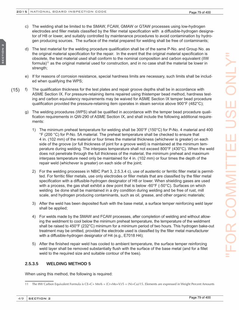
49
NATIONAL BOARD INSPECTION CODE2015
SECTION 2
SEC
TIO
N 2
c) The welding shall be limited to the SMAW, FCAW, GMAW or GTAW processes using low-hydrogen electrodes and filler metals classified by the filler metal specification with a diffusible-hydrogen designa-tor of H8 or lower, and suitably controlled by maintenance procedures to avoid contamination by hydro-gen producing sources. The surface of the metal prepared for welding shall be free of contaminants;
d) The test material for the welding procedure qualification shall be of the same P-No. and Group No. as the original material specification for the repair. In the event that the original material specification is obsolete, the test material used shall conform to the nominal composition and carbon equivalent (IIW formula)11 as the original material used for construction, and in no case shall the material be lower in strength;
e) If for reasons of corrosion resistance, special hardness limits are necessary, such limits shall be includ-ed when qualifying the WPS;
f) The qualification thickness for the test plates and repair groove depths shall be in accordance with ASME Section IX. For pressure-retaining items repaired using thistemper bead method, hardness test-ing and carbon equivalency requirements may be waived for ASME Section IX temper bead procedure qualification provided the pressure-retaining item operates in steam service above 900°F (482°C);
g) The welding procedures (WPS) shall be qualified in accordance with the temper bead procedure quali-fication requirements in QW-290 of ASME Section IX, and shall include the following additional require-ments:
1) The minimum preheat temperature for welding shall be 300°F (150°C) for P-No. 4 material and 400 °F (200 °C) for P-No. 5A material. The preheat temperature shall be checked to ensure that 4 in. (102 mm) of the material or four times the material thickness (whichever is greater) on each side of the groove (or full thickness of joint for a groove weld) is maintained at the minimum tem-perature during welding. The interpass temperature shall not exceed 800°F (430°C). When the weld does not penetrate through the full thickness of the material, the minimum preheat and maximum interpass temperature need only be maintained for 4 in. (102 mm) or four times the depth of the repair weld (whichever is greater) on each side of the joint;
2) For the welding processes in NBIC Part 3, 2.5.3.4 c), use of austentic or ferritic filler metal is permit-ted. For ferritic filler metals, use only electrodes or filler metals that are classified by the filler metal specification with a diffusible-hydrogen designator of H8 or lower. When shielding gases are used with a process, the gas shall exhibit a dew point that is below -60°F (-50°C). Surfaces on which welding be done shall be maintained in a dry condition during welding and be free of rust, mill scale, and hydrogen producing contaminants, such as oil, grease, and other organic materials;
3) After the weld has been deposited flush with the base metal, a surface temper reinforcing weld layer shall be applied;
4) For welds made by the SMAW and FCAW processes, after completion of welding and without allow-ing the weldment to cool below the minimum preheat temperature, the temperature of the weldment shall be raised to 450°F (232°C) minimum for a minimum period of two hours. This hydrogen bake-out treatment may be omitted, provided the electrode used is classified by the filler metal manufacturer with a diffusible-hydrogen designator of H4 (e.g., E7018 H4);
5) After the finished repair weld has cooled to ambient temperature, the surface temper reinforcing weld layer shall be removed substantially flush with the surface of the base metal (and for a fillet weld to the required size and suitable contour of the toes).
2.5.3.5 WELDING METHOD 5
When using this method, the following is required:
11 The IIW Carbon Equivalent Formula is CE=C+ Mn/6 + (Cr+Mo+V)/5 + (Ni+Cu)/15. Elements are expressed in Weight Percent Amounts
(15)
"FO
RC
OM
MIT
TEE
US
EO
NLY
"
Page 79 of 400
Page 79 of 400
50
2015
SECTION 2
SEC
TIO
N 2
NB-23
a) This welding method may be used when the applicable rules of the original code of construction or the construction standard or code selected permit joining dissimilar materials used in pressure-retaining items;
b) The materials shall be limited to ASME P-No. 1, Groups 1, 2, and 3, P-No. 3, Groups 1, 2, and 3, P-No. 4, P-No. 5A, P-No. 9A, P-No. 10A, P-No. 10B, P-No. 10C, P-No. 11A, P-No. 11B joined to either P-No. 8, P-No. 42, P-No. 43, or P-No. 45, as permitted for welded construction by the applicable rules of the original code of construction;
c) The welding shall be limited to the SMAW, FCAW, GMAW and machine or automatic GTAW process-es. The filler metal used for joining the dissimilar materials shall be either A-No 8 or Nickel-Chrome alloy classification (F-No 43). When selecting a filler metal for dissimilar metal weld joints, determine if the weld joint will be exposed to elevated temperature service. A-No 8 filler metals exposed to service temperatures greater than 800°F (427°C) will exhibit reduced creep life along the fusion zone of the ferritic material due to carbon diffusion. Instead, a low hydrogen, Nickel-Chromium alloy classification filler metal shall be used for dissimilar weld joints exposed to service temperatures at or above 800°F (427°C);
d) The WPS shall be qualified in accordance with the temper bead rules of QW-290 in ASME Section IX.For pressure retaining items fabricated to ASME Section I and repaired using this temper bead method, hardness testing and carbon equivalency requirements may be waived for ASME Section IX temper bead procedure qualification provided the pressure retaining item operates in steam service above 900°F (482°C);
e) If the original code of construction did not require notch toughness testing, qualification of welding procedures (WPS) for joining ASME P-No. 1, P-No. 3 ferritic materials to either P-No. 8, P-No. 42, P-No. 43, or P-No. 45 materials shall be in accordance with requirements in either NBIC Part 3, 2.5.3.1, Welding Method 1 or in NBIC Part 3, 2.5.3.3, Welding Method 3;
f) If the original code of construction did not require notch toughness testing, qualification of welding pro-cedures (WPS) for joining ASME P-No. 4, P-No. 5A ferritic materials to either P-No. 8, P-No. 42, P-No. 43, P-No. 45 materials shall be in accordance with the requirements in NBIC Part 3, 2.5.3.4, Welding Method 4;
g) If the original code of construction required notch toughness testing, qualification of welding procedures (WPS) for joining ferritic materials to either P-No. 8, P-No. 42, P-No. 43, or P-No. 45 materials shall be in accordance with the requirements in NBIC Part 3, 2.5.3.2, Welding Method 2.
2.5.3.6 WELDING METHOD 6
This welding method provides guidance for welding only Grade 91 tube material within the boiler setting and when it’s impracticable to perform local postweld heat treatment (PWHT). This repair method utilizes a con-trolled fill technique.
When using this welding method, the following is required:
a) This method is limited to butt welds in tubing NPS 5 (DN 125) or less in diameter and ½ in. (13 mm) or less in wall thickness for which the applicable rules of the original code of construction did not require notch toughness testing;
b) Application shall be limited to only boiler tube repairs at a location internal to the boiler setting;
c) Upon the completion of weld repair, the repair region shall be kept from humid or moist environments until the return to service;
1) The material shall be limited to P-No 15E, Group 1, Grade 91, creep strength enhanced ferritic steel (CSEF).
(15)
"FO
RC
OM
MIT
TEE
US
E(15)
US
E(15)
ON
LY"
ON
LY"
ON
LY"
SEC
TIO
N 2
ON
LY"
SEC
TIO
N 2
Page 80 of 400
Page 80 of 400
51
NATIONAL BOARD INSPECTION CODE2015
SECTION 2
SEC
TIO
N 2
2) The welding shall be limited to the SMAW or GTAW processes, manual or automatic, using suitably controlled maintenance procedures to avoid contamination by hydrogen producing sources. The surface of the metal shall be free of contaminants and kept dry.
3) The test material for the welding procedure qualification shall be P-No 15 E, Group 1, Grade 91 for the repair.
4) Qualification thickness for the test plates and repair groove depths shall be in accordance with ASME Section IX, QW-451.
5) The Welding Procedure Specification (WPS) shall be qualified in accordance with the requirements of ASME Section IX, except that no postweld heat treatment shall be applied to the test coupon. Additionally, the qualification shall include the following requirements:
a. The minimum preheat for the GTAW process shall be 200°F (93°C). The minimum preheat for the SMAW process shall be 300°F (150°C). The preheat temperature shall be checked to ensure the minimum preheat temperature is maintained during welding and until welding is completed. The maximum interpass temperature shall be 400°F (200°C).
b. When the SMAW process is specified for a fill pass layer as a controlled filled welding tech-nique, the electrode diameter is restricted to a maximum size of 1/8 in. (3.2 mm). When the GTAW-process is specified any limits in filler size is to be reflected in the qualified PQR and WPS.
c. Regardless of the welding process (SMAW or GTAW), only the use of stringer beads shall be permitted.
d. The filler metal shall be limited to an austenitic, nickel-base filler metal having a designation F-No. 43 and limited to the following consumables: ERNiCr-3 (Filler Metal 82), ENiCrFe-3 (IN-CONEL Welding Electrode 182), ENiCrFe-2 (INCO-WELD A), ASME B&PV Code Cases 2733 and 2734 (EPRI P87).
"FO
RC
OM
MIT
TEE
US
EO
NLY
"
Page 81 of 400
Page 81 of 400
52
2015
SECTION 3
SEC
TIO
N 3
NB-23
PART 3, SECTION 3 REPAIRS AND ALTERATIONS — REQUIREMENTS FOR
REPAIRS AND ALTERATIONS
3.1 SCOPE
This section provides general and specific requirements for materials, replacement parts, and methods used when performing repairs and alterations to pressure-retaining items. Specific repair or alteration methods for other types of pressure equipment are in NBIC Part 3, Section 7.
3.2 GENERAL REQUIREMENTS FOR REPAIRS AND ALTERATIONS
3.2.1 MATERIAL REQUIREMENTS FOR REPAIRS AND ALTERATIONS
a) The materials used in making repairs or alterations shall conform insofar as possible to the original code of construction or construction standard or code selected, including the material specification requirements used for the work planned. Carbon or alloy steel having a carbon content of more than 0.35% shall not be welded unless permitted by the original code of construction. The “R” Certificate Holder is responsible for verifying identification of existing materials from original data, drawings, or pressure-retaining item records, and identification of the materials to be installed. Consideration shall be given to the condition of the existing material, especially in the weld preparation area. If the existing material cannot be verified (unknown), the “R” Certificate Holder shall perform a chemical analysis and hardness testing, as a minimum, of the unknown material to verify its weldability and strength or may elect to qualify a weld procedure. If there is a question with regard to the weldability characteristics of the material, then competent technical advice should be obtained.
b) For corrugating rolls manufactured per the requirements of paragraph UF-7 of ASME Section VIII, Div. 1, weld overlay of the surfaces is permitted for all classes of SA-649 forging material and an exception to the 0.35% carbon limit is permitted. The requirements to qualify welding procedures and welder per-formance shall be in accordance with ASME Section IX for hard facing (wear resistance) and/or corro-sion resistant overlays. Preheat or post weld heat treatment is neither required or prohibited.
3.2.2 REPLACEMENT PARTS
Replacement parts to be used in repairs or alterations shall meet the following applicable requirements:
a) Replacement parts that will be subject to internal or external pressure that consist of new materials which should be formed to the required shape by casting, spinning, forging, die forming, and on which no fabrication welding is performed, shall be supplied as material. Such parts shall be marked with the material and part identification and the name or trademark of the parts manufacturer. In lieu of full iden-tification marking on the material or part, the part manufacturer may use a coded marking system trace-able to the original marking. Such markings shall be considered as the parts manufacturer’s certification that the part complies with the original code of construction. Examples include seamless or welded tubes or pipe, forged nozzles, heads or tubesheets, or subassemblies attached together mechanically;
b) Replacement parts that will be subject to internal or external pressure that are preassembled by attach-ment welds shall have the welding performed in accordance with the original code of construction. The supplier or manufacturer shall certify that the material and fabrication are in accordance with the original code of construction. This certification shall be supplied in the form of bills of material and drawings with statement of certification. Examples include boiler furnace wall or floor panel assemblies, prefab-ricated openings in boiler furnace walls, such as burner openings, air ports, inspection openings, or sootblower openings;
"FO
RC
OM
MIT
TEE
US
EO
NLY
"O
NLY
"O
NLY
"S
EC
TIO
N 3
ON
LY"
SEC
TIO
N 3
Page 82 of 400
Page 82 of 400

53
NATIONAL BOARD INSPECTION CODE2015
SECTION 3
SEC
TIO
N 3
c) When ASME Code is the original code of construction, replacement parts subject to internal or external pressure fabricated by welding, which require inspection by an Authorized Inspector shall be fabricated by an organization having an appropriate ASME Certificate of Authorization. The item shall be inspected and stamped as required by the applicable section of the ASME Code. A completed ASME Manufactur-er’s Partial Data Report shall be supplied by the manufacturer;
The “R” Certificate Holder, using replacement parts fabricated and certified to an ASME Code edition and addenda different from that used for the original construction, shall consider and seek technical advice, where appropriate, for change or conflicts in design, materials, welding, heat treatment, examinations and tests to ensure a safe repair/alteration is performed. Note that work once classified as a repair could now be considered an alteration;
d) When the original code of construction is other than ASME Code, replacement parts subject to internal or external pressure, fabricated by welding, shall be manufactured by an organization certified as re-quired by the original code of construction. The item shall be inspected and stamped as required by the original code of construction. Certification to the original code of construction, as required by the original code of construction or equivalent, shall be supplied with the item. When this is not possible or practi-cable, the organization fabricating the part shall have a National Board “R” Certificate of Authorization; replacement parts shall be documented on Form R-3 and the “R” Symbol Stamp applied as described in NBIC Part 3, Section 5.
3.2.3 DRAWINGS
As appropriate, drawings shall be prepared to describe the repair or alteration. Drawings shall include suffi-cient information to satisfactorily perform the repair or alteration.
3.2.4 DESIGN REQUIREMENTS FOR REPAIRS AND ALTERATIONS
a) Many repairs may not require drawings or design calculations when the original code of construction is known and drawings and/or a Manufacturer’s Data Report is available;
b) The “R” Certificate Holder performing repairs and alterations shall establish the construction standard or code and sufficient controls to ensure that all required design information, applicable drawings, design calculations, specifications, and instructions are prepared, obtained, controlled, and interpreted to provide the basis for a repair or an alteration in accordance with the original code of construction. When a Manufacturer’s Data Report is required by the original construction standard, a copy of the original data report shall be obtained, where available, for use in the design of the repair or alteration. When the original Manufacturer’s Data Report cannot be obtained, agreements on the method of establishing design basis for the repair or alteration shall be obtained from the Inspector and the Jurisdiction, when required.
3.2.5 CALCULATIONS
For alterations, calculations shall be completed prior to the start of any physical work. All design calculations shall be completed by an organization experienced in the design portion of the standard used for construction of the item. All calculations shall be made available for review by the Inspector accepting the design.
3.2.6 REFERENCE TO OTHER CODES AND STANDARDS
Other codes, standards, and practices pertaining to the repair and alteration of pressure retaining items can provide useful guidance. Use of these codes, standards and practices is subject to review and acceptance by the Inspector, and when required, by the Jurisdiction. The user is cautioned that the referenced codes, standards and practices may address methods categorized as repairs; however, some of these methods are considered alterations by the NBIC.
"FO
RC
OM
MIT
TEE
US
EO
NLY
"
Page 83 of 400
Page 83 of 400

54
2015
SECTION 3
SEC
TIO
N 3
NB-23
In the event of a conflict with the requirements of the NBIC, the requirements of the NBIC take precedence.Some examples are as follows:a) National Board BULLETIN - National Board Classic Articles Series;
b) ASME PCC-1, Guidelines for Pressure Boundary Bolted Flange Joint Assembly;
c) ASME PCC-2, Repair of Pressure Equipment and Piping.
3.2.7 CHANGE OF SERVICE
See NBIC Part 2, Supplement 9 for requirements and guidelines to be followed when a change of service or service type is made to a pressure retaining item.
Whenever there is a change of service, the local jurisdiction where the pressure retaining item is to be oper-ated, shall be notified for acceptance, when applicable. Any specific jurisdictional requirements shall be met.
3.3 REPAIRS TO PRESSURE-RETAINING ITEMS
3.3.1 DEFECT REPAIRS
Before a repair is made to a defect in a welded joint or base metal, care should be taken to investigate its cause and to determine its extent and likelihood of recurrence.
3.3.2 ROUTINE REPAIRS
a) Routine repairs are repairs for which the requirements for in-process involvement by the Inspector and stamping by the “R” Certificate Holder may be waived as determined appropriate by the Jurisdiction and the Inspector. All other applicable requirements of this code shall be met. Prior to performing routine re-pairs, the “R” Certificate Holder should determine that routine repairs are acceptable to the Jurisdiction where the pressure-retaining item is installed;
b) The Inspector, with the knowledge and understanding of jurisdictional requirements, shall be responsi-ble for meeting jurisdictional requirements and the requirements of this code;
c) The “R” Certificate Holder’s Quality System Program shall describe the process for identifying, con-trolling, and implementing routine repairs. Routine repairs shall be documented on Form R-1 with this statement in the Remarks section: “Routine Repair”;
d) Alternative welding methods without posteweld heat treatment as described in NBIC Part 3, 2.5.3 shall not be used for routine repairs.
e) Repairs falling within one or more of the following categories may be considered routine:
1) Welded repairs or replacements of valves, fittings, tubes, or pipes NPS 5 (DN 125) in diameter and smaller, or sections thereof, where neither postweld heat treatment nor NDE other than visual is required by the original code of construction. This includes their attachments such as clips, lugs, skirts, etc., but does not include nozzles to pressure-retaining items;
2) The addition or repair of nonload bearing attachments to pressure-retaining items where postweld heat treatment is not required;
3) Weld buildup of wasted areas in heads, shells, flanges and fittings not exceeding an area of 100 sq. inches (64,520 sq. mm) or a thickness of 25% of nominal wall thickness or ½ inch (13 mm), which-ever is less;
(15)
"FO
RC
OM
MIT
TEE
US
EO
NLY
"O
NLY
"O
NLY
"S
EC
TIO
N 3
ON
LY"
SEC
TIO
N 3
(15)
ON
LY"
(15)
Page 84 of 400
Page 84 of 400
55
NATIONAL BOARD INSPECTION CODE2015
SECTION 3
SEC
TIO
N 3
4) Corrosion resistance weld overlay not exceeding 100 sq. in. (64,520 sq. mm).
3.3.3 EXAMPLES OF REPAIRS
a) Weld repairs or replacement of pressure parts or attachments that have failed in a weld or in the base material;
b) The addition of welded attachments to pressure parts, such as:
1) Studs for insulation or refractory lining;
2) Hex steel or expanded metal for refractory lining;
3) Ladder clips;
4) Brackets having loadings that do not affect the design of the pressure-retaining item to which they are attached; and
5) Tray support rings.
c) Corrosion resistant strip lining, or weld overlay;
d) Weld buildup of wasted areas;
e) Replacement of heat exchanger tubesheets in accordance with the original design;
f) Replacement of boiler and heat exchanger tubes where welding is involved;
g) In a boiler, a change in the arrangement of tubes in furnace walls, economizers, or super heater sections;
h) Replacement of pressure-retaining parts identical to those existing on the pressure-retaining item and described on the original Manufacturer’s Data Report. For example:
1) Replacement of furnace floor tubes and/or sidewall tubes in a boiler;
2) Replacement of a shell or head in accordance with the original design;
3) Rewelding a circumferential or longitudinal seam in a shell or head;
4) Replacement of nozzles of a size where reinforcement is not a consideration.
i) Installation of new nozzles or openings of such a size and connection type that reinforcement and strength calculations are not a consideration required by the original code of construction;
j) The addition of a nozzle where reinforcement is a consideration may be considered to be a repair, pro-vided the nozzle is identical to one in the original design, located in a similar part of the vessel, and not closer than three times its diameter from another nozzle. The addition of such a nozzle shall be restrict-ed by any service requirements;
k) The installation of a flush patch to a pressure-retaining item;
l) The replacement of a shell course in a cylindrical pressure vessel;
m) Welding of gage holes;
n) Welding of wasted or distorted flange faces;
o) Replacement of slip-on flanges with weld neck flanges or vice versa;
"FO
RC
OM
MIT
TEE
US
EO
NLY
"
Page 85 of 400
Page 85 of 400
56
2015
SECTION 3
SEC
TIO
N 3
NB-23
p) Seal welding of buttstraps and rivets;
q) Subject to the administrative procedures of the Jurisdiction and approval of the Inspector, the replace-ment of a riveted section or part by welding;
r) The repair or replacement of a pressure part with a code-accepted material that has a nominal compo-sition and strength that is equivalent to the original material, and is suitable for the intended service; and
s) Replacement of a pressure-retaining part with a material of different nominal composition and, equal to or greater in allowable stress from that used in the original design, provided the replacement mate-rial satisfies the material and design requirements of the original code of construction under which the vessel was built. The minimum required thickness shall be at least equal to the thickness stated on the original Manufacturer’s Data Report.
t) The replacement of a pressure relieving device (PRD) attached by welding, provided the replacement device’s relieving capacity is equal to or greater than the PRD capacity required by the original code of construction.
3.3.4 REPAIR METHODS
3.3.4.1 SCOPE
Except as provided in NBIC Part 3, 3.3.4.8, a repair of a defect in a welded joint or base material shall not be made until the defect has been removed. A suitable nondestructive examination (NDE) method, such as magnetic particle (MT) or liquid penetrant (PT), may be necessary to ensure complete removal of the defect. If the defect penetrates the full thickness of the material, the repair shall be made with a full penetration weld such as a double buttweld or single buttweld with or without backing. Where circumstances indicate that the defect is likely to recur, consideration should be given to removing the defective area and installing a flush patch or taking other corrective measures acceptable to the Inspector, and when required, by the Jurisdiction.
3.3.4.2 DEFECT REPAIRS
a) Cracks
Except as provided in NBIC Part 3, 3.3.4.8, a repair of a crack in a welded joint or base material shall not be made until the defect has been removed. A suitable nondestructive examination method such as a MT or PT may be necessary to ensure complete removal of the defect. If the defect penetrates the full thickness of the material, the repair shall be made with a full penetration weld such as a double buttweld or single buttweld with or without backing, as allowed by the original code of construction.
b) Unstayed Boiler Furnace Cracks
Cracks at the knuckle or at the turn of the flange of the furnace opening require immediate replacement of the affected area or specific approval of repairs by the Jurisdiction (See NBIC Part 3, Figure 3.3.4.2-a).
c) Rivet or Staybolt Hole Cracks
Cracks radiating from rivet or staybolt holes may be repaired if the plate is not seriously damaged. If the plate is seriously damaged, it shall be replaced. For suggested methods of repair, see NBIC Part 3, Fig-ure 3.3.4.2-b.
d) Minor Defects
Minor cracks, isolated pits, and small plate imperfections should be examined to determine the extent of the defect and whether repair by welding is required. Except as provided in NBIC Part 3, 3.3.4.8 prior
"FO
RC
OM
MIT
TEE
US
EO
NLY
"O
NLY
"O
NLY
"S
EC
TIO
N 3
ON
LY"
SEC
TIO
N 3
Page 86 of 400
Page 86 of 400

57
NATIONAL BOARD INSPECTION CODE2015
SECTION 3
SEC
TIO
N 3
to repair by welding, the defects shall be removed to sound metal. Liquid penetrant or magnetic particle examination may be used before or after welding.
e) Defective Bolting
Defective bolting material shall not be repaired but shall be replaced with suitable material that meets the specifications of the original code of construction.
f) Bulges
1) A bulge on a watertube shall be investigated to determine the cause and extent of damage to the tube prior to repair. If the bulge has resulted in metallurgical changes to the original tube material, as determined by field metallography, installation of a new length of tubing or tube patch (see NBIC Part 3, 3.3.4.6 b) is required. If the bulge has cracks as determined by NDE, installation of a new length of tubing or a tube patch is required. If the bulge does not exhibit cracks and has not result-ed in metallurgical changes to the original tube material, a mechanical repair may be considered subject to the concurrence of the Inspector or Jurisdiction.
2) A bulge on a plate shall be investigated to determine the cause and extent of damage to the plate prior to repair. If the bulge has resulted in metallurgical changes to the original plate material, as determined by field metallography, installation of a flush patch (see NBIC Part 3, 3.3.4.6 a)) is required. If the plate has cracks as determined by NDE, installation of a flush patch is required. If the bulge does not exhibit cracks and has not resulted in metallurgical changes to the original plate material, a mechanical repair may be considered, subject to the concurrence of the Inspector or Jurisdiction.
g) Blisters
A blister may be caused by a defect in the metal such as lamination where one side exposed to the fire overheats but the other side retains its strength due to the cooling effect of the water. After the blistered material has been removed, the remaining wall thickness shall be determined by ultrasonic thickness testing. A surface examination using liquid penetrant testing or magnetic particle testing shall be made to ensure the remaining material contains no defects. If the remaining wall thickness is adequate, in the judgment of the Inspector, the area may be repaired by welding as covered in NBIC Part 3, 3.3.4.3. If the remaining wall thickness is not adequate, a plate will require a flush patch (See NBIC Part 3, 3.3.4.6 a)) and a tube will require a new length of tube or tube patch (see NBIC Part 3, 3.3.4.6 b)).
"FO
RC
OM
MIT
TEE
US
EO
NLY
"
Page 87 of 400
Page 87 of 400
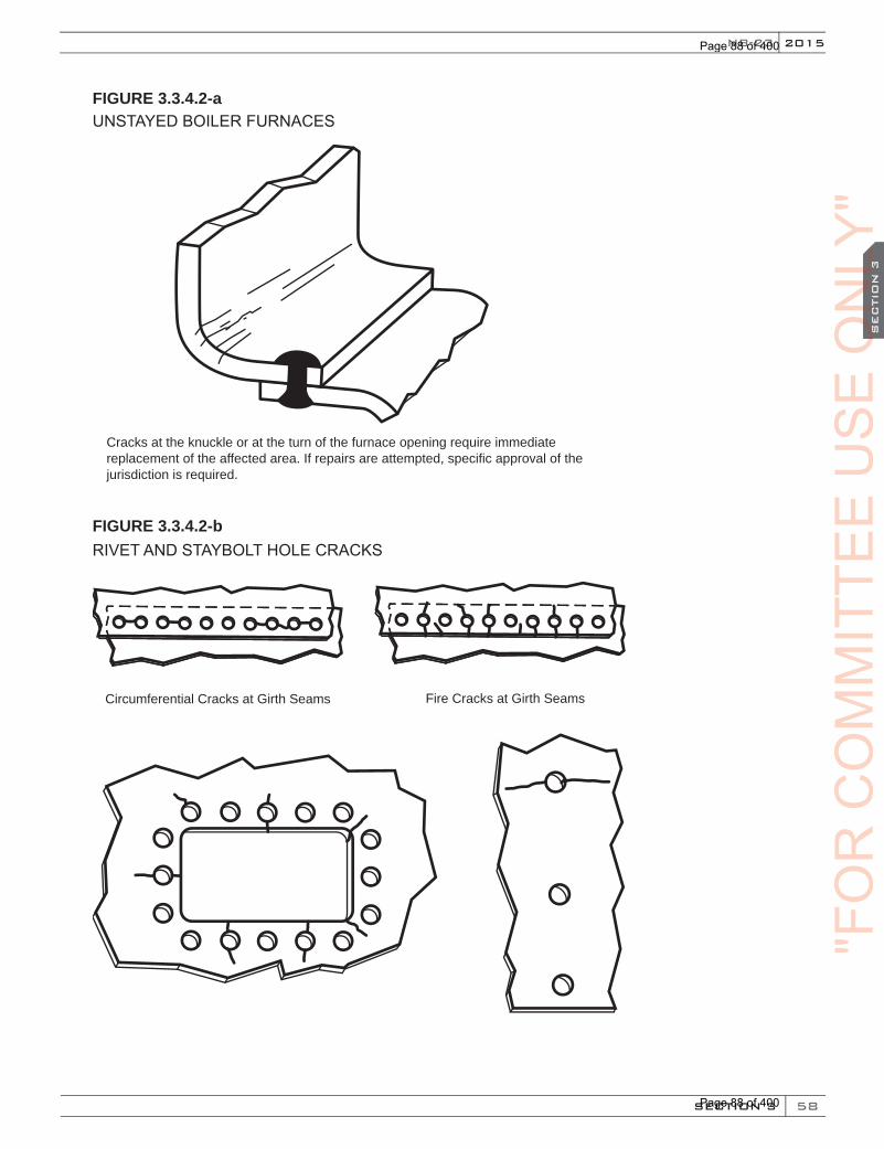
58
2015
SECTION 3
SEC
TIO
N 3
NB-23
FIGURE 3.3.4.2-aUNSTAYED BOILER FURNACES
Cracks at the knuckle or at the turn of the furnace opening require immediate replacement of the affected area. If repairs are attempted, specific approval of the jurisdiction is required.
FIGURE 3.3.4.2-bRIVET AND STAYBOLT HOLE CRACKS
Fire Cracks at Girth SeamsCircumferential Cracks at Girth Seams
"FO
RC
OM
MIT
TEE
US
EO
NLY
"O
NLY
"O
NLY
"S
EC
TIO
N 3
ON
LY"
SEC
TIO
N 3
Page 88 of 400
Page 88 of 400

59
NATIONAL BOARD INSPECTION CODE2015
SECTION 3
SEC
TIO
N 3
Cracks radiating from rivet or staybolt holes should be repaired if the plate is not seriously damaged. If the plate is seri-ously damaged, it shall be replaced. A suggested repair method is described below:
a) Prior to welding, the rivets or staybolts from which the cracks extend and the adjacent rivets (or staybolts if appro-priate) should be removed;
b) In riveted joints, tack bolts should be placed in alternate holes to hold the plate laps firmly;
c) The cracks should then be prepared for welding by chipping, grinding, or gouging;
d) In riveted joints, cracks which extend past the inner edge of the plate lap should be welded from both sides;
e) Rivet holes should be reamed before new rivets are driven;
f) Threaded staybolt holes should be retapped and new staybolts properly driven and headed.
3.3.4.3 WASTED AREAS
a) Shells, Drums, Headers
Wasted areas in stayed and unstayed shells, drums, and headers may be built up by welding, provided that in the judgment of the Inspector the strength of the structure has not been impaired. Where extensive weld buildup is employed, the Inspector may require an appropriate method of NDE for the completed surface of the repair. For suggested methods of building up wasted areas by welding. (See NBIC Part 3, Figure 3.3.4.3-a).
b) Access Opening
Wasted areas around access openings may be built up by welding or they may be repaired as described in NBIC Part 3, Figure 3.3.4.3-b.
c) Flanges
Wasted flange faces may be cleaned thoroughly and built up with weld metal. They should be machined in place, if possible, to a thickness not less than that of the original flange or that required by calculations in accordance with the provisions of the original code of construction. Wasted flanges may also be re-ma-chined in place without building up with weld metal, provided the metal removed in the process does not reduce the thickness of the flange to a measurement below that calculated above. Flanges that leak because of warpage or distortion and which cannot be re-machined shall be replaced with new flanges that have at least the dimensions conforming to the original code of construction.
d) Tubes
1) Wasted areas on tubes may be repaired by welding, provided that, in the judgment of the Inspector the strength of the tube has not been impaired. Where deemed necessary, competent technical ad-vice should be obtained from the manufacturer or from another qualified source. This may be nec-essary when considering such items as size limitations of repaired areas, minimum tube thickness to be repaired, tube environment, location of the tube in the boiler, and other similar conditions.
2) The WPS followed shall be qualified for weld metal buildup in accordance with ASME Section IX. When the code of construction required postweld heat treatment (PWHT) for butt welds, the WPS followed for the weld buildup, shall be qualified with PWHT.
e) External Weld Metal Buildup
1) Pressure-retaining items that have localized internal thinning due to erosion and/or corrosion and where the internal surface is not readily accessible may be weld repaired by depositing weld metal on the external surface of the item as shown in NBIC Part 3, Figure 3.3.4.3-c. This method of repair is subject to approval by the Inspector and the Jurisdiction, where required.
"FO
RC
OM
MIT
TEE
US
EO
NLY
"
Page 89 of 400
Page 89 of 400
60
2015
SECTION 3
SEC
TIO
N 3
NB-23
2) All of the following conditions shall apply for this repair method to be permitted:
a. The component to be repaired shall be a ferrous material;
b. The maximum design temperature of the repaired component shall not exceed 650°F (340°C), and the minimum design temperature shall not be less than -20°F (-29°C);
c. The pressure-retaining item shall be volumetrically examined for cracks in the area to be weld repaired. If cracks are detected, this repair method shall NOT be used;
d. The WPS followed shall be qualified for weld metal buildup in accordance with ASME Section IX. The nominal chemical analysis of the deposited weld metal shall be equivalent to the base material that is to be repaired. In addition, the nominal tensile strength of the deposited weld metal shall be equal to or exceed the specified minimum tensile strength and shall be based on the requirements of the welding consumable. If butt welds in the component being overlaid required postweld heat treatment by the code of construction, the WPS followed for the weld buildup shall be qualified with PWHT;
e. The pressure-retaining item shall be taken out of service prior to performing the weld metal buildup. The owner of the pressure-retaining item shall evaluate the flammability, volatility, or potential reaction of the contents that were in the vessel to ensure safe working conditions during weld repair. When required by the results of this evaluation, the pressure-retaining item shall be drained of its contents to the extent necessary to make the repair;
f. This method may be used more than once in the same areas to repair locally thinned areas; however, the cumulative weld buildup for all repairs shall not exceed the thickness (t) of the component at any point;
g. Repairs using this method shall not cover more than 25% of the circumference of the component.
3) External weld buildup shall be applied in accordance with the following requirements:
a. The area to be repaired shall be ultrasonically scanned for wall thickness, and the location and size of the thinned region shall be mapped;
b. The area requiring repairs and the boundaries of the weld buildup shall be marked on the external surface of the component;
c. The general design of the external weld buildup shall be in accordance with NBIC Part 3, Figure 3.3.4.3-c. The finished weld buildup shall be circular, oval, or rectangular in shape;
d. The weld buildup shall extend, at full thickness, a minimum distance B in each direction beyond the boundaries of the thinned base metal area.
1. B = 3/4 √(Rtnom)
2. R = outer radius of the component, or D/2
3. tnom = nominal wall thickness of the component
The thickness shall be sufficient to maintain the predicted life of the repair. Any corrosion allowance that is determined to be necessary shall be added to the value of B.
e. All edges of the weld buildup shall be tapered to the existing contour of the component, at a maximum angle (a) of 45°;
"FO
RC
OM
MIT
TEE
US
EO
NLY
"O
NLY
"O
NLY
"S
EC
TIO
N 3
ON
LY"
SEC
TIO
N 3
Page 90 of 400
Page 90 of 400
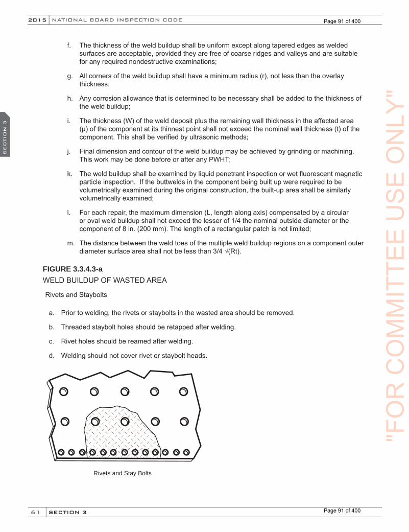
61
NATIONAL BOARD INSPECTION CODE2015
SECTION 3
SEC
TIO
N 3
f. The thickness of the weld buildup shall be uniform except along tapered edges as welded surfaces are acceptable, provided they are free of coarse ridges and valleys and are suitable for any required nondestructive examinations;
g. All corners of the weld buildup shall have a minimum radius (r), not less than the overlay thickness.
h. Any corrosion allowance that is determined to be necessary shall be added to the thickness of the weld buildup;
i. The thickness (W) of the weld deposit plus the remaining wall thickness in the affected area (µ) of the component at its thinnest point shall not exceed the nominal wall thickness (t) of the component. This shall be verified by ultrasonic methods;
j. Final dimension and contour of the weld buildup may be achieved by grinding or machining. This work may be done before or after any PWHT;
k. The weld buildup shall be examined by liquid penetrant inspection or wet fluorescent magnetic particle inspection. If the buttwelds in the component being built up were required to be volumetrically examined during the original construction, the built-up area shall be similarly volumetrically examined;
l. For each repair, the maximum dimension (L, length along axis) compensated by a circular or oval weld buildup shall not exceed the lesser of 1/4 the nominal outside diameter or the component of 8 in. (200 mm). The length of a rectangular patch is not limited;
m. The distance between the weld toes of the multiple weld buildup regions on a component outer diameter surface area shall not be less than 3/4 √(Rt).
FIGURE 3.3.4.3-aWELD BUILDUP OF WASTED AREA
Rivets and Staybolts
a. Prior to welding, the rivets or staybolts in the wasted area should be removed.
b. Threaded staybolt holes should be retapped after welding.
c. Rivet holes should be reamed after welding.
d. Welding should not cover rivet or staybolt heads.
Rivets and Stay Bolts
"FO
RC
OM
MIT
TEE
US
EO
NLY
"
Page 91 of 400
Page 91 of 400
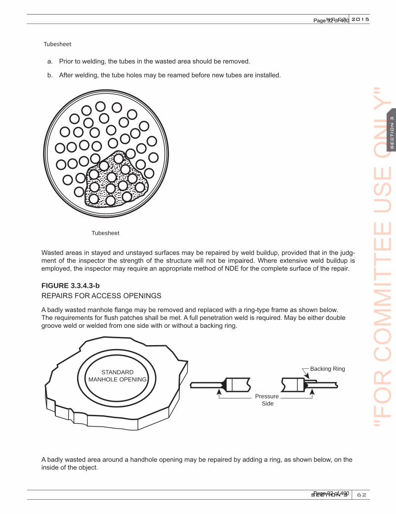
62
2015
SECTION 3
SEC
TIO
N 3
NB-23
Tubesheet
a. Prior to welding, the tubes in the wasted area should be removed.
b. After welding, the tube holes may be reamed before new tubes are installed.
Tubesheet
Wasted areas in stayed and unstayed surfaces may be repaired by weld buildup, provided that in the judg-ment of the inspector the strength of the structure will not be impaired. Where extensive weld buildup is employed, the inspector may require an appropriate method of NDE for the complete surface of the repair.
FIGURE 3.3.4.3-bREPAIRS FOR ACCESS OPENINGS
A badly wasted manhole flange may be removed and replaced with a ring-type frame as shown below. The requirements for flush patches shall be met. A full penetration weld is required. May be either double groove weld or welded from one side with or without a backing ring.
Pressure Side
STANDARDMANHOLE OPENING
Backing Ring
A badly wasted area around a handhole opening may be repaired by adding a ring, as shown below, on the inside of the object.
"FO
RC
OM
MIT
TEE
US
EO
NLY
"O
NLY
"O
NLY
"S
EC
TIO
N 3
ON
LY"
SEC
TIO
N 3
Page 92 of 400
Page 92 of 400
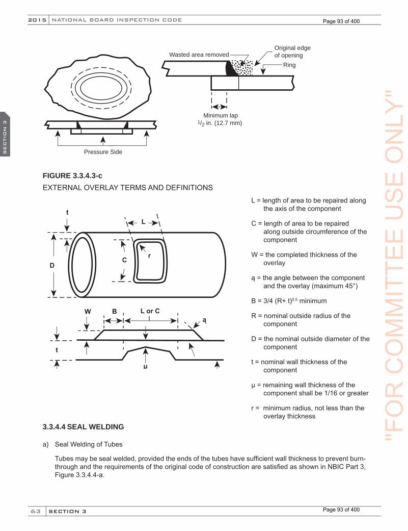
63
NATIONAL BOARD INSPECTION CODE2015
SECTION 3
SEC
TIO
N 3
Pressure Side
Minimum lap1/2 in. (12.7 mm)
Wasted area removed
Ring
Original edge of opening
FIGURE 3.3.4.3-cEXTERNAL OVERLAY TERMS AND DEFINITIONS
L = length of area to be repaired along the axis of the component
C = length of area to be repaired along outside circumference of the component
W = the completed thickness of the overlay
ą = the angle between the component and the overlay (maximum 45°)
B = 3/4 (R+ t)0.5 minimum
R = nominal outside radius of the component
D = the nominal outside diameter of the component
t = nominal wall thickness of the component
µ = remaining wall thickness of the component shall be 1/16 or greater
r = minimum radius, not less than the overlay thickness
D
W B L or C
C r
Lt
t
ą
µInside Surface
3.3.4.4 SEAL WELDING
a) Seal Welding of Tubes
Tubes may be seal welded, provided the ends of the tubes have sufficient wall thickness to prevent burn-through and the requirements of the original code of construction are satisfied as shown in NBIC Part 3, Figure 3.3.4.4-a.
"FO
RC
OM
MIT
TEE
US
EO
NLY
"
Page 93 of 400
Page 93 of 400
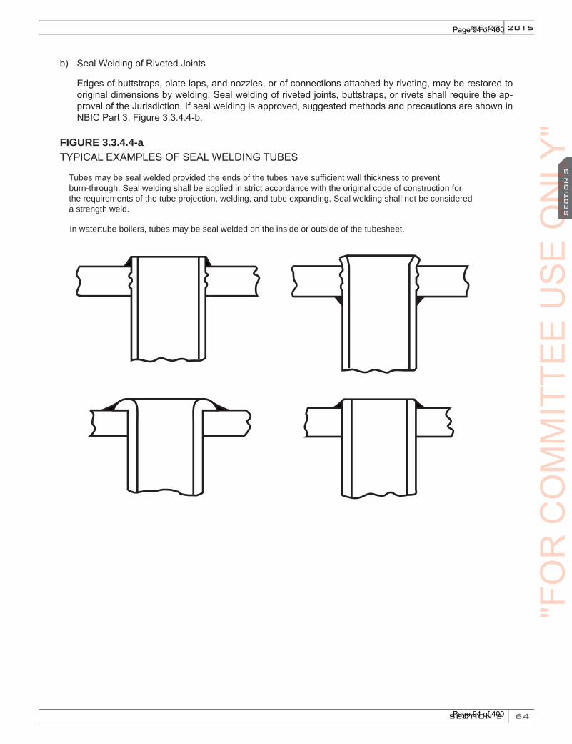
64
2015
SECTION 3
SEC
TIO
N 3
NB-23
b) Seal Welding of Riveted Joints
Edges of buttstraps, plate laps, and nozzles, or of connections attached by riveting, may be restored to original dimensions by welding. Seal welding of riveted joints, buttstraps, or rivets shall require the ap-proval of the Jurisdiction. If seal welding is approved, suggested methods and precautions are shown in NBIC Part 3, Figure 3.3.4.4-b.
FIGURE 3.3.4.4-aTYPICAL EXAMPLES OF SEAL WELDING TUBES
Tubes may be seal welded provided the ends of the tubes have sufficient wall thickness to prevent burn-through. Seal welding shall be applied in strict accordance with the original code of construction for the requirements of the tube projection, welding, and tube expanding. Seal welding shall not be considered a strength weld.
In watertube boilers, tubes may be seal welded on the inside or outside of the tubesheet.
"FO
RC
OM
MIT
TEE
US
EO
NLY
"O
NLY
"O
NLY
"S
EC
TIO
N 3
ON
LY"
SEC
TIO
N 3
Page 94 of 400
Page 94 of 400
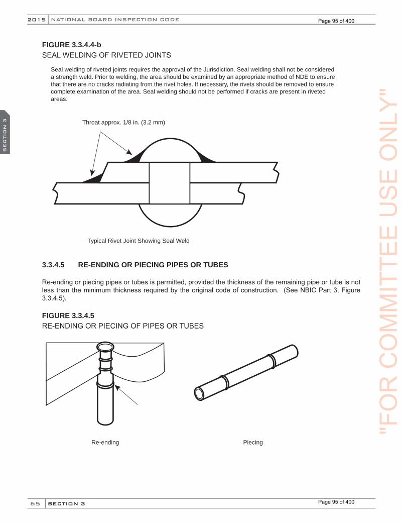
65
NATIONAL BOARD INSPECTION CODE2015
SECTION 3
SEC
TIO
N 3
FIGURE 3.3.4.4-bSEAL WELDING OF RIVETED JOINTS
Seal welding of riveted joints requires the approval of the Jurisdiction. Seal welding shall not be considered a strength weld. Prior to welding, the area should be examined by an appropriate method of NDE to ensure that there are no cracks radiating from the rivet holes. If necessary, the rivets should be removed to ensure complete examination of the area. Seal welding should not be performed if cracks are present in riveted areas.
Throat approx. 1/8 in. (3.2 mm)
Typical Rivet Joint Showing Seal Weld
3.3.4.5 RE-ENDING OR PIECING PIPES OR TUBES
Re-ending or piecing pipes or tubes is permitted, provided the thickness of the remaining pipe or tube is not less than the minimum thickness required by the original code of construction. (See NBIC Part 3, Figure 3.3.4.5).
FIGURE 3.3.4.5RE-ENDING OR PIECING OF PIPES OR TUBES
Re-ending Piecing
"FO
RC
OM
MIT
TEE
US
EO
NLY
"
Page 95 of 400
Page 95 of 400

66
2015
SECTION 3
SEC
TIO
N 3
NB-23
3.3.4.6 PATCHES
a) Flush Patches
1) The weld around a flush patch shall be a full penetration weld and the accessible surfaces shall be ground flush where required by the applicable original code of construction. Examples of flush weld-ed patches are shown in NBIC Part 3, Figure 3.3.4.6-a. The welds shall be subjected to the nonde-structive examination method used in the original code of construction or an alternative acceptable to the Inspector.
2) Before installing a flush patch, the defective material should be removed until sound material is reached. The patch should be rolled to the proper shape or curvature. The edges should align without overlap. In stayed areas, the weld seams should come between staybolt rows or riveted seams. Patches shall be made from a material whose composition and thickness meet the intended service. Patches may be any shape or size. If the patch is rectangular, an adequate radius should be provided at the corners. Square corners should be avoided. The completed welds shall meet the requirements of the original code of construction.
b) Tube Patches
In some situations it is necessary to weld a flush patch on a tube, such as when replacing tube sections and accessibility around the complete circumference of the tube is restricted, or when it is necessary to repair a small bulge. This is referred to as a window patch. Suggested methods for window patches are shown in NBIC Part 3, Figure 3.3.4.6-b.
FIGURE 3.3.4.6-aFLUSH PATCH CONFIGURATIONS IN UNSTAYED AREAS
FLUSH PATCHES IN STAYED AREAS
"FO
RC
OM
MIT
TEE
US
EO
NLY
"O
NLY
"O
NLY
"S
EC
TIO
N 3
ON
LY"
SEC
TIO
N 3
Page 96 of 400
Page 96 of 400
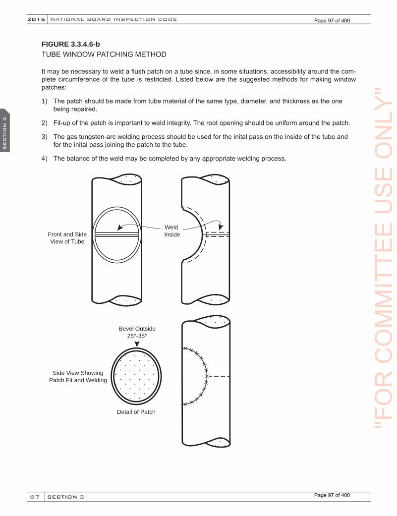
67
NATIONAL BOARD INSPECTION CODE2015
SECTION 3
SEC
TIO
N 3
FIGURE 3.3.4.6-bTUBE WINDOW PATCHING METHOD
It may be necessary to weld a flush patch on a tube since, in some situations, accessibility around the com-plete circumference of the tube is restricted. Listed below are the suggested methods for making window patches:
1) The patch should be made from tube material of the same type, diameter, and thickness as the one being repaired.
2) Fit-up of the patch is important to weld integrity. The root opening should be uniform around the patch.
3) The gas tungsten-arc welding process should be used for the inital pass on the inside of the tube and for the inital pass joining the patch to the tube.
4) The balance of the weld may be completed by any appropriate welding process.
Bevel Outside25°-35°
Detail of Patch
Side View ShowingPatch Fit and Welding
Weld InsideFront and Side
View of Tube
"FO
RC
OM
MIT
TEE
US
EO
NLY
"
Page 97 of 400
Page 97 of 400

68
2015
SECTION 3
SEC
TIO
N 3
NB-23
3.3.4.7 STAYS
Threaded stays may be replaced by welded-in stays provided that, in the judgement of the Inspector, the material adjacent to the staybolt has not been materially weakened by deterioration or wasting away. Require-ments of the original code of construction governing welded-in stays shall be met.
3.3.4.8 REPAIR OF PRESSURE-RETAINING ITEMS WITHOUT COMPLETE REMOVAL OF DEFECTS
a) There may be cases where removal of a defect in a pressure-retaining item is not practical at the time the defect is found. In such cases, with approval of the Inspector and, when required, the Jurisdiction, an engineering evaluation shall be performed to determine the scope of the repair and impact to safety prior to returning the pressure-retaining item to service for a specified period of time. The engineering evaluation shall be performed by an organization with demonstrated competency in defect (and flaw) characterization of pressure-retaining items. The method of defect evaluation and time interval for re-turning the pressure-retaining item back to service shall be as agreed upon by the Inspector, and when required, the Jurisdiction. The specified period of time the defect can remain in service after weld repair shall be based on no measureable defect growth during subsequent inspections, or a period of time as specified by the Jurisdiction, if applicable. This repair method is not permitted for vessels used in lethal service, vessels designed for high-cycle operation or fatigue service, compressed air storage, and in cases where high stress concentration cannot be reduced by weld repair. This repair method is not permitted for DOT vessels.
b) One or more fitness-for-service engineering evaluation methods as described in NBIC Part 2, 4.4 shall be used to determine whether the defect may remain, either in part or in whole, in the pressure-retaining item. If it is determined that the defect can remain in the item, a risk-based inspection program shall be developed to assure inspection of the defect and monitoring of defect growth over time. This program shall be a controlled and documented inspection program that specifies inspection intervals as agreed upon with the Inspector and, when required, the Jurisdiction, and shall be maintained until the defect can be completely removed and the item repaired.
c) The following requirements shall apply to the weld repair of pressure-retaining items without complete removal of defects:
1) Engineering evaluation of the defect in the pressure-retaining item shall be conducted using one or more fitness-for-service condition assessment method(s) as described in NBIC Part 2, 4.4. Engineering evaluation of the condition assessment results shall be performed by an organization that has demonstrated industry experience in evaluating pressure-retaining items as referenced in NBIC, Part 2, S5.3.
2) If engineering evaluation indicates a defect can remain in the pressure-retaining item, a risk-based inspection program shall be developed and implemented based on review and acceptance by the Inspector and, when required, the Jurisdiction. The risk-based inspection program shall be in accor-dance with the requirements in NBIC, Part 2 4.4.
3) The fitness-for-service condition assessment and risk-based inspection programs shall remain in effect for the pressure-retaining item until such time that the defect can be completely removed and the item repaired. The fitness-for-service condition assessment method, results of assessment, and method of weld repair shall be documented on a Report of Fitness for Service Assessment (FFSA) Form as described in NBIC Part 2, 4.4.1 and shall be filed with the Jurisdiction, when required.
4) When weld repairs are performed without complete removal of the defect(s), this shall be noted on the Form R-1 in the description of the work. The “R” Stamp Holder performing the weld repairs shall provide detailed information on the Form R-1, describing the method and extent of repair and include the specific location of the repair on the item.
"FO
RC
OM
MIT
TEE
US
EO
NLY
"O
NLY
"O
NLY
"S
EC
TIO
N 3
ON
LY"
SEC
TIO
N 3
Page 98 of 400
Page 98 of 400
69
NATIONAL BOARD INSPECTION CODE2015
SECTION 3
SEC
TIO
N 3
5) The interval to either re-inspect or remove the item from service for repair shall be determined based on a risk-based inspection program developed and implemented as required by NBIC Part 3, 3.3.4.8. The inspection interval shall not exceed the remaining life of the item, and shall be docu-mented on the FFSA Form and in the Remarks section of the Form R-1. The FFSA Form shall be affixed to the Form R-1 when weld repairs are performed in NBIC Part 3, 3.3.4.8.
6) A copy of the completed Form R-1 with the completed FFSA Form attached may be registered with the National Board, and when required, filed with the Jurisdiction where the item was installed.
3.3.4.9 TUBE PLUGGING IN FIRETUBE BOILERS
When the replacement of a tube in a firetube boiler is not practicable at the time the defective tube is detected, with the concurrence of the owner, Inspector, and when required, the Jurisdiction, the tube may be plugged using the following course of repair:
a) The scope of work, type of plug and method of retention; whether welded or mechanical interface, shall be evaluated by the “R” Certificate Holder performing the repair and reviewed with the Inspector, and when required, the Jurisdiction.
b) When the method of plugging is by welding, strength calculations for the size of the weld shall be in accordance with the original code of construction. The “R” Certificate Holder performing this repair shall weld the plug to the tube, or to the tube sheet, or a combination of both.
c) Plugging a tube in a firetube boiler is recognized as an alternative to the replacement of a firetube and may be further limited as a method of repair by the number of tubes plugged and their location; scat-tered or clustered. The operational effects on the waterside pressure boundary or membrane and the effects on the combustion process throughout the boiler should be considered prior to plugging.
d) The boiler may be returned to service for a period of time agreed upon by the owner, the Inspector, and when required, the Jurisdiction.
e) The Form R-1 shall be completed for the plugging of firetubes, identifying the means of plug retention; mechanical or by welding.
3.3.5 REPAIR OF ASME SECTION VIII, DIVISION 2 OR 3, PRESSURE VESSELS
3.3.5.1 SCOPE
The following requirements shall apply for the repair of pressure vessels constructed to the requirements of Section VIII, Division 2 or 3, of the ASME Code.
3.3.5.2 REPAIR PLAN
The user shall prepare, or cause to have prepared, a detailed plan covering the scope of the repair.
a) Engineer Review and Certification
The repair plan shall be reviewed and certified by an engineer meeting the criteria of ASME Section VIII, Division 2 or 3, as applicable, for an engineer signing and certifying a Manufacturer’s Design Report. The review and certification shall be such as to ensure the work involved in the repair is compatible with the User’s Design Specification and the Manufacturer’s Design Report.
Note: The engineer qualification criteria of the Jurisdiction where the pressure vessel is installed should be verified before selecting the certifying engineer.
(15)
"FO
RC
OM
MIT
TEE
US
EO
NLY
"
Page 99 of 400
Page 99 of 400
70
2015
SECTION 3
SEC
TIO
N 3
NB-23
b) Authorized Inspection Agency Acceptance
Following review and certification, the repair plan shall be submitted for acceptance to the Authorized Inspection Agency/Owner-User Inspection Organization whose Inspector will make the acceptance in-spection and sign the Form R-1.
3.4 ALTERATIONS
3.4.1 RE-RATING12
Re-rating of a pressure-retaining item by increasing the maximum allowable working pressure (internal or external) or temperature or decreasing the minimum design metal temperature below which notch toughness testing is required by the original code of construction, shall be done only after the following requirements have been met to the satisfaction of the Jurisdiction at the location of the installation:
a) Revised calculations verifying the new service conditions shall be prepared in accordance with the “R” Certificate Holder’s Quality Control System. Establishing a higher joint efficiency to re-rate a pres-sure-retaining item is not permitted;
b) All re-ratings shall be established in accordance with the requirements of the construction standard to which the pressure-retaining item was built;
c) Current inspection records verify that the pressure-retaining item is satisfactory for the proposed service conditions;
d) The pressure-retaining item has been pressure tested, as required, for the new service conditions. Any insulation, coatings, or coverings that may inhibit or compromise a meaningful pressure test shall be removed, to the extent identified by the Inspector;
e) In lieu of pressure testing, alternative methods can be used to ensure the structural integrity of the re-rated pressure-retaining item. The alternative methods shall be documented and subject to review and approval by the Jurisdiction.
3.4.2 ALTERATIONS BASED ON ALLOWABLE STRESS VALUES
For re-rating or re-calculating a new minimum wall thickness for a pressure-retaining item using a later edi-tion/addenda of the original code of construction or selected construction standard or code that permits use of higher allowable material stress values than were used in the original construction, the following requirements shall apply:
a) The “R” Certificate Holder shall verify, by calculations and other means, that the re-rated item can be satisfactorily operated at the new service condition (e.g., stiffness, buckling, external mechanical loadings);
b) The pressure-retaining item shall not be used in lethal service;
c) The pressure-retaining item shall not be used in high-cycle operation or fatigue service (i.e., loadings other than primary membrane stress are controlling design considerations) unless the pressure-retain-ing item was originally designed for fatigue service and a fatigue analysis is performed;
d) The pressure-retaining item shall have been constructed to the 1968 edition or later edition/addenda of the original code of construction;
12 Re-rating: Except as provided for Yankee dryers in Supplement 5, this code does not provide rules for de-rating boilers or pressure vessels; however, when the MAWP and/or allowable temperature of a boiler or pressure vessel is reduced, the Jurisdiction where the object is installed should be contacted to determine if specific procedures should be followed.
"FO
RC
OM
MIT
TEE
US
EO
NLY
"O
NLY
"O
NLY
"S
EC
TIO
N 3
ON
LY"
SEC
TIO
N 3
Page 100 of 400
Page 100 of 400

71
NATIONAL BOARD INSPECTION CODE2015
SECTION 3
SEC
TIO
N 3
e) The pressure-retaining item shall be shown to comply with all relevant requirements of the edition/addenda of the code of construction, which permits the higher allowable stress values (e.g., reinforce-ment, toughness, examination, pressure testing);
f) The pressure-retaining item shall have a satisfactory operating history and current inspection of the pressure-retaining item shall verify the item exhibits no unrepaired damage (e.g., cracks, corrosion, erosion). Areas of corrosion or erosion may be left in place provided the remaining wall thickness is greater than the minimum thickness for the new design conditions;
g) The re-rating shall be acceptable to the Inspector and, where required, the Jurisdiction;
h) All other requirements of Part 3, as applicable, and jurisdictional requirements shall be met;
i) Use of this paragraph shall be documented in the “Remarks” section of Form R-2.
3.4.3 EXAMPLES OF ALTERATIONS
a) An increase in the maximum allowable working pressure (internal or external) or temperature of a pres-sure-retaining item regardless of whether or not a physical change was made to the pressure-retaining item;
b) A decrease in the minimum temperature;
c) The addition of new nozzles or openings in a boiler or pressure vessel except those classified as repairs;
d) A change in the dimensions or contour of a pressure-retaining item;
e) In a boiler, an increase in the heating surface or steaming capacity as described on the original Manu-facturer’s Data Report;
f) The addition of a pressurized jacket to a pressure vessel;
g) Except as permitted in NBIC Part 3, 3.3.3 s); replacement of a pressure retaining part in a pressure retaining item with a material of different allowable stress or nominal composition from that used in the original design;
h) The addition of a bracket or an increase in loading on an existing bracket that affects the design of the pressure-retaining item to which it is attached;
i) The replacement of a pressure relieving device (PRD) as a result of work completed on a pressure-re-taining item (PRI) that changes the resultant capacity to exceed the minimum requiredrelieving capacity (MRRC) required by the original code of construction as described on the original Manufacturer’s Data Report.
3.4.4 ALTERATION OF ASME CODE SECTION VIII, DIVISION 2 OR 3, PRESSURE VESSELS
3.4.4.1 ALTERATION PLAN
a) Engineer Review and Certification
The alteration plan shall be reviewed and certified by an engineer meeting the criteria of ASME Section VIII, Division 2 or 3, as applicable, for an engineer signing and certifying a Manufacturer’s Design Report. The review and certification shall be such as to ensure the work involved in the alteration is compatible with the user’s design specification and the Manufacturer’s Design Report.
"FO
RC
OM
MIT
TEE
US
EO
NLY
"
Page 101 of 400
Page 101 of 400
72
2015
SECTION 3
SEC
TIO
N 3
NB-23
Note: The engineer qualification criteria of the jurisdiction where the pressure vessel is installed should be verified before selecting the certifying engineer.
b) User’s Design Specification
If the alteration is such that the work is not compatible with, or changes one or more requirement(s) of the original user’s design specification, the user’s design specification shall be revised by the user with the new parameters or changes. The revisions shall be certified by an engineer meeting the criteria of ASME Section VIII, Division 2 or 3, as applicable, for an engineer signing and certifying a Manufacturer’s Design Report.
Note: The engineer qualification criteria of the Jurisdiction where the pressure vessel is installed should be verified before selecting the certifying engineer.
c) Manufacturer’s Design Report
The “R” Certificate Holder shall prepare, or cause to have prepared a supplement to the Manufacturer’s Design Report to reconcile the new parameters or changes with the user’s design specification.
The supplement to the Manufacturer’s Design Report shall be certified by an engineer meeting the criteria of ASME Section VIII, Division 2 or 3, as applicable, for an engineer signing and certifying a Manufactur-er’s Design Report.
Note: The engineer qualification criteria of the Jurisdiction where the pressure vessel is installed should be verified before selecting the certifying engineer.
d) Authorized Inspection Agency Acceptance
Following review and certification, the alteration plan shall be submitted for acceptance to the Authorized Inspection Agency/Owner-User Inspection Organization whose inspector will make the acceptance in-spection and sign the Form R-2.
"FO
RC
OM
MIT
TEE
US
EO
NLY
"O
NLY
"O
NLY
"S
EC
TIO
N 3
ON
LY"
SEC
TIO
N 3
Page 102 of 400
Page 102 of 400

73
NATIONAL BOARD INSPECTION CODE2015
SECTION 4
SEC
TIO
N 4
PART 3, SECTION 4 REPAIRS AND ALTERATIONS — EXAMINATION AND TESTING
4.1 SCOPE
This section provides requirements and guidelines for performing examinations and tests for repairs and alterations to pressure-retaining items.
4.2 NONDESTRUCTIVE EXAMINATION
a) The nondestructive examination (NDE) requirements, including technique, extent of coverage, proce-dures, personnel qualification, and acceptance criteria, shall be in accordance with the original code of construction for the pressure-retaining item. Weld repairs and alterations shall be subjected to the same nondestructive examination requirements as the original welds. Where this is not possible or practica-ble, alternative NDE methods acceptable to the Inspector and the Jurisdiction where the pressure-re-taining item is installed, where required, may be used.
b) NDE personnel shall be qualified and certified in accordance with the requirements of the original code of construction. When this is not possible or practicable, NDE personnel may be qualified and certified in accordance with their employer’s written practice. ASNT SNT-TC-1A, Recommended Practice Non-destructive Testing Personnel Qualification and Certification (2006 edition), or ASNT CP-189, Standardfor Qualification and Certification of Nondestructive Testing Personnel (2006 edition), shall be used as a guideline for employers to establish their written practice. The ASNT Central Certification Program (ACCP, Rev. 3, Nov. 1997) may be used to fulfill the examination and demonstration requirements of the employer’s written practice. Provisions for training, experience, qualification, and certification of NDE personnel shall be described in the “R” Certificate Holder’s written quality system.
4.3 PRESSURE GAGES, MEASUREMENT, EXAMINATION, AND TEST EQUIPMENT
The calibration of pressure gages, measurement, examination, and test equipment, and documentation of calibration shall be performed, as required, by the applicable standard used for construction.
4.4 EXAMINATION AND TEST FOR REPAIRS AND ALTERATIONS
The following requirements shall apply to all repairs and alterations to pressure-retaining items:
a) The integrity of repairs, alterations, and replacement parts used in repairs and alterations shall be veri-fied by examination or test;
b) Testing methods used shall be suitable for providing meaningful results to verify the integrity of the repair or alteration. Any insulation, coatings, or coverings that may inhibit or compromise a meaningful test method shall be removed, to the extent identified by the Inspector;
c) The “R” Certificate Holder is responsible for all activities relating to examination and test of repairs and alterations;
d) Examinations and tests to be used shall be subject to acceptance of the Inspector and, where required, acceptance of the Jurisdiction.
4.4.1 TEST OR EXAMINATION METHODS APPLICABLE TO REPAIRS
Based on the nature and scope of the repair activity, one or a combination of the following examination and test methods shall be applied to repairs and replacement parts used in repairs.
"FO
RC
OM
MIT
TEE
US
EO
NLY
"
Page 103 of 400
Page 103 of 400

74
2015
SECTION 4
SEC
TIO
N 4
NB-23
a) Liquid Pressure Test
Pressure testing of repairs shall meet the following requirements:
1) Pressure tests shall be conducted using water or other liquid medium. The test pressure shall be the minimum required to verify the leak tightness integrity of the repair, but not more than 150% of the maximum allowable working pressure (MAWP) stamped on the pressure-retaining items, as ad-justed for temperature. When original test pressure included consideration of corrosion allowance, the test pressure may be further adjusted based on the remaining corrosion allowance.
2) During a pressure test where the test pressure will exceed 90% of the set pressure of the pressure relief device, the device shall be removed whenever possible. If not possible, a spindle restraint may be used following the valve manufacturer’s instructions and recommendations. Extreme caution should be employed to ensure only enough force is applied to contain pressure. Excessive mechanical force applied to the spindle restraint may result in damage to the seat and/or spindle and may interfere with the proper operation of the valve. The spindle restraint shall be removed following the test.
The organization that performs the pressure test and applies a spindle restraint shall attach a metal tag that identifies the organization and date the work was performed to the pressure relieving device. If the seal was broken, the organization shall reseal the adjustment housing with a seal that identifies the responsible organization. The process shall be acceptable to the Jurisdiction where the pres-sure-retaining items are installed.
3) The metal temperature for the pressure test shall be in accordance with the original code of con-struction, but not less than 60°F (16°C) unless the owner provides information on the toughness characteristics of the material to indicate the acceptability of a lower test temperature. For thick walled pressure retaining items, it is recommended to seek technical guidance in establishing the notch toughness characteristics of the steel prior to pressure testing so that the metal temperature may be warmed above 60° F (16°C) to avoid brittle fracture. During close examination the metal temperature shall not exceed 120°F (49°C), unless the owner specified requirements for a higher test temperature, and it is acceptable to the Inspector.
4) Table 4.4.1 may be used for liquid pressure testing of steels supplied as coarse-grained under the following specifications;ASME SA 212,ASME SA 515, andASME SA 299
If supplied as coarse-grained, the above steels can exhibit low toughness at room temperature and in lieu of conducting notch toughness tests, Table 4.4.1 and Table 4.4.1 M can be used to establish a temperature for the liquid to reduce the risk of brittle fracture. Table 4.4.1 and Table 4.4.1 M contain minimum liquid temperature requirements based on metal thickness of the pressure retaining part.
5) Hold-time for the pressure test shall be a minimum of 10 minutes prior to examination by the In-spector. Where the test pressure exceeds the MAWP of the item, the test pressure shall be reduced to the MAWP for close examination by the Inspector. Hold-time for close examination shall be as necessary for the Inspector to conduct the examination.
"FO
RC
OM
MIT
TEE
US
EU
SE
US
ES
EC
TIO
N 4
US
ES
EC
TIO
N 4O
NLY
"O
NLY
"O
NLY
"
Page 104 of 400
Page 104 of 400
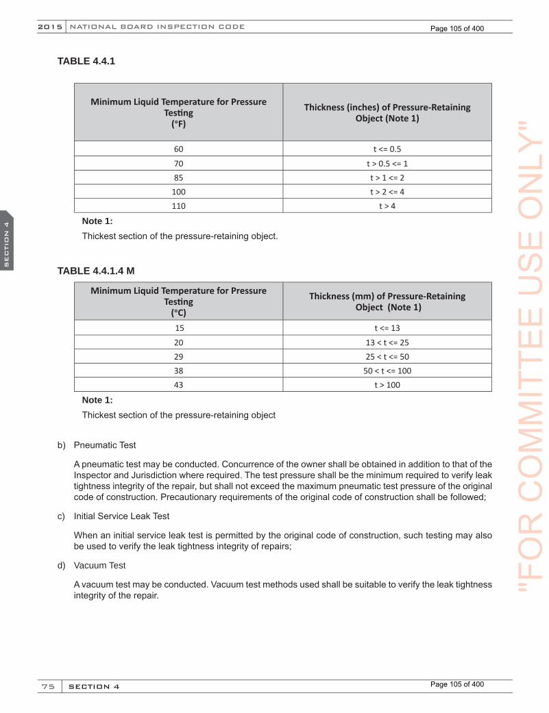
75
NATIONAL BOARD INSPECTION CODE2015
SECTION 4
SEC
TIO
N 4
TABLE 4.4.1
Minimum Liquid Temperature for Pressure Testing
(°F)
Thickness (inches) of Pressure-Retaining Object (Note 1)
60 t <= 0.5
70 t > 0.5 <= 1 85 t > 1 <= 2
100 t > 2 <= 4 110 t > 4
Note 1: Thickest section of the pressure-retaining object.
TABLE 4.4.1.4 M
Minimum Liquid Temperature for Pressure Testing
(°C)
Thickness (mm) of Pressure-Retaining Object (Note 1)
15 t <= 13
20 13 < t <= 2529 25 < t <= 5038 50 < t <= 10043 t > 100
Note 1: Thickest section of the pressure-retaining object
b) Pneumatic Test
A pneumatic test may be conducted. Concurrence of the owner shall be obtained in addition to that of the Inspector and Jurisdiction where required. The test pressure shall be the minimum required to verify leak tightness integrity of the repair, but shall not exceed the maximum pneumatic test pressure of the original code of construction. Precautionary requirements of the original code of construction shall be followed;
c) Initial Service Leak Test
When an initial service leak test is permitted by the original code of construction, such testing may also be used to verify the leak tightness integrity of repairs;
d) Vacuum Test
A vacuum test may be conducted. Vacuum test methods used shall be suitable to verify the leak tightness integrity of the repair. "F
OR
CO
MM
ITTE
EU
SE
ON
LY"
Page 105 of 400
Page 105 of 400
76
2015
SECTION 4
SEC
TIO
N 4
NB-23
e) Nondestructive Examination (NDE)
NDE may be conducted. NDE methods used shall be suitable for providing meaningful results to verify the integrity of the repair. Exclusive use of visual examination (VT) is only permitted with the following considerations:
1) When a pressure test or alternative NDE methods other than visual examination, are not practica-ble the exclusive use of direct VT as an NDE method shall be limited to routine repairs, as identified in NBIC Part 3, 3.3.2.
2) For each repair being considered, the exclusive use of direct VT as an NDE method shall be ac-ceptable to the Inspector, and where required, the Jurisdiction.
3) As a minimum, direct VT shall be performed after the root weld layer or first-pass is deposited, and the final weld surface. Other weld layers shall be examined as identified by the Inspector and, where required, the Jurisdiction.
4) Personnel completing direct VT shall be qualified and certified in accordance with paragraph NBIC Part 3, 4.2- b), AWS QC-1, or any nationally recognized standard acceptable to the Jurisdiction. Visual acuity shall be demonstrated using as a minimum, standard J-2 letters on standard Jaeger test type charts for near vision.
5) Direct VT shall be performed in accordance with a written procedure meeting the procedure and reporting requirements listed in the original code of construction or ASME Section V, Article 9.
4.4.2 TEST OR EXAMINATION METHODS APPLICABLE TO ALTERATIONS
Based on the nature and scope of the alterations activity, one or a combination of the following examination and test methods shall be applied to alterations and replacement parts used in alterations.
a) Liquid Pressure Test
Pressure testing of alterations shall meet the following requirements:
1) A pressure test as required by the original code of construction shall be conducted. The test pres-sure shall not exceed 150% of the maximum allowable working pressure (MAWP) stamped on the pressure-retaining item, as adjusted for temperature. When the original test pressure included con-sideration of corrosion allowance, the test pressure may be further adjusted based on the remain-ing corrosion allowance. The pressure test for replacement parts may be performed at the point of manufacture or point of installation;
2) As an alternative to pressure testing connecting welds in accordance with the original code of con-struction, connecting welds may be tested or examined in accordance with the rules for repairs (see NBIC Part 3, 4.4.1). Connecting welds are defined as welds attaching the replacement part to the pressure-retaining item;
3) During a pressure test where the test pressure will exceed 90% of the set pressure of the pressure relief device, the device shall be removed whenever possible. If not possible, a spindle restraint may be used following the valve manufacturer’s instructions and recommendations. Extreme caution should be employed to ensure only enough force is applied to contain pressure. Excessive mechanical force applied to the spindle restraint may result in damage to the seat and/or spindle and may interfere with the proper operation of the valve. The spindle restraint shall be removed following the test.
a. The organization that performs the pressure test and applies a spindle restraint shall attach a metal tag that identifies the organization and date the work was performed to the pressure relieving device. If the seal was broken, the organization shall reseal the adjustment housing
"FO
RC
OM
MIT
TEE
US
EU
SE
US
ES
EC
TIO
N 4
US
ES
EC
TIO
N 4O
NLY
"O
NLY
"O
NLY
"
Page 106 of 400
Page 106 of 400
77
NATIONAL BOARD INSPECTION CODE2015
SECTION 4
SEC
TIO
N 4
with a seal that identifies the responsible organization. The process shall be acceptable to the Jurisdiction where the pressure-retaining items are installed;
4) The metal temperature for the pressure test shall be in accordance with the original code of con-struction, but not less than 60°F (16°C), unless the owner provides information on the toughness characteristics of the material to indicate the acceptability of a lower test temperature. For thick walled pressure-retaining items, it is recommended to seek technical guidance in establishing the notch toughness characteristics of the steel prior to pressure testing so that the metal temperature may be warmed above 60°F (16°C) to avoid brittle fracture. During close examination, the metal temperature shall not exceed 120°F (49°C), unless the owner specifies requirements for a higher test temperature and it is acceptable to the Inspector;
5) Unless it can be demonstrated that the material has been supplied as fine grained, it is recom-mended that Table 4.4.1.4 or 4.4.1.4 M be followed for pressure testing of steels supplied under the following specifications:
ASME SA 212,
ASME SA 515, and
ASME SA 299
6) Hold-time for the pressure test shall be a minimum of 10 minutes prior to examination by the Inspector. Where the test pressure exceeds the MAWP of the item, the test pressure shall be reduced to the MAWP for close examination by the Inspector. Hold-time for close examination shall be as necessary for the Inspector to conduct the examination.
b) Pneumatic Test
A pneumatic test may be conducted when contamination of the pressure-retaining item by liquids is pos-sible or when liquid pressure testing is not practicable. Concurrence of the owner shall be obtained in addition to the Inspector and Jurisdiction where required. Pneumatic test requirements and precautions shall be in accordance with the original code of construction.
c) Nondestructive Examination
NDE may be conducted when contamination of the pressure-retaining item by liquids is possible or when pressure testing is not practicable. Concurrence of the owner shall be obtained in addition to the Inspec-tor, and where required, the Jurisdiction. Exclusive use of Visual Examination (VT) shall not be permitted. In all cases NDE methods or combination of methods used shall be suitable for providing meaningful results to verify the integrity of the alteration.
4.5 PRESSURE RELIEF VALVE PERFORMANCE TESTING AND TESTING EQUIPMENT
Each pressure relief valve to which the “VR” repair symbol stamp is to be applied shall be subjected to the following tests by the repair certificate holder.
4.5.1 TEST MEDIUM AND TESTING EQUIPMENT
Valves marked for steam service, or having special internal parts for steam service, shall be tested on steam. Valves marked for air, gas, or vapor service shall be tested with air or gas. Valves marked for liquid service shall be tested with water or other suitable liquid. ASME Code, Section IV hot-water valves, shall be tested on water, steam, or air.
a) Each valve shall be tested to demonstrate the following:
"FO
RC
OM
MIT
TEE
US
EO
NLY
"
Page 107 of 400
Page 107 of 400
78
2015
SECTION 4
SEC
TIO
N 4
NB-23
1) Set pressure (as defined by the valve manufacturer and as listed in NB-18, Pressure Relief Device Certifications);
2) Response to blowdown, when required by the original code of construction;
3) Seat tightness; and
4) For valves designed to discharge to a closed system, the tightness of the secondary pressure zone shall be tested as required by the original code of construction.
b) The equipment used for the performance testing prescribed above shall meet the following requirements:
1) The performance testing equipment shall include a pressure vessel of adequate volume and pres-sure source capacity to ensure compliance with NBIC Part 3, 4.5.1 a) 1).
2) Prior to use, all performance testing equipment shall be qualified by the certificate holder to en-sure that the equipment and testing procedures will provide accurate results when used within the ranges established for that equipment. This qualification may be accomplished by benchmark testing, comparisons to equipment used for verification testing as specified in the quality system, or comparisons to field performance. This qualification shall be documented and provisions made to retain such documentation for a period of at least five years after the testing equipment is retired. Documentation of this qualification shall include, but not be limited to:
a. Schematic of the performance test equipment;
b. Size and pressure ranges of valves to be tested and the test fluid to be used;
c. Dimensions of test vessels;
d. Accuracy of pressure measuring equipment;
e. Size and design type of valves used to control flow; and
f. Method of qualifying.
3) Prior to the implementation of any addition or modification to the testing equipment that would alter the contents of the document required in NBIC Part 3, 4.5.1 b) 2), the certificate holder shall re-qualify the performance test equipment in accordance with NBIC Part 3, 4.5.1 b) 2). If the equip-ment changed was used to satisfy the requirements of verification testing, the certificate holder shall notify the National Board and additional verification testing, in accordance with the quality system, may be required.
4.5.2 OWNER-USER ASME CODE SECTION VIII STEAM TESTING
When ASME Code Section VIII valves are repaired by the owner for the owner’s own use, valves for steam service may be tested on air for set pressure and, if possible, blowdown adjustment, provided the valve man-ufacturer’s corrections for differential in set pressure between steam and air are applied to the set pressure.
4.5.3 LIFT ASSIST TESTING
a) A device may be used to apply an auxiliary lifting load on the spring of a repaired valve to establish the set pressure in lieu of the tests required in NBIC Part 3, 4.5.1 a) 1) when such testing at full pressure:
1) May cause damage to the valve being tested; or
2) Is impractical when system design considerations preclude testing at full pressure.
"FO
RC
OM
MIT
TEE
US
EU
SE
US
ES
EC
TIO
N 4
US
ES
EC
TIO
N 4O
NLY
"O
NLY
"O
NLY
"
Page 108 of 400
Page 108 of 400
79
NATIONAL BOARD INSPECTION CODE2015
SECTION 4
SEC
TIO
N 4
b) While actual valve blowdown and valve performance characteristics cannot be verified, valve set pres-sure may be determined to an acceptable degree of accuracy using this testing technique provided, as a minimum, that:
1) equipment utilized is calibrated as required in the quality system; including, but not limited to:
a. System pressure measurement equipment;
b. Lifting force measurement equipment; and
c. Other measuring elements required by the device manufacturer.
2) the device and test procedures that have proved to give accurate results are used and followed;
3) a static inlet pressure is applied with the test medium specified in NBIC Part 3, 4.5.1; and
4) adjustments are made in accordance with the valve manufacturer’s recommendations to ensure proper lift and blowdown.
c) Prior to use, all lift assist devices shall be qualified by the certificate holder to ensure that the equipment and testing procedures will provide accurate results when used within the ranges established for that equipment used for verification testing as specified in the quality system or comparisons to field perfor-mance. This qualification shall be documented and provisions made to retain such documentation for a period of at least five years after the lift assist device is retired. Documentation of this qualification shall include but not be limited to:
1) A description of the lift assist device including model number, serial number and manufacturer.
2) Size and pressure ranges of valves to be tested with the lift assist device and the test fluid to be used.
Note: Maximum set pressure is determined by available lift force and system pressure.
3) Accuracy of pressure measuring equipment.
4) Method of qualifying.
d) After initial qualification of the device the device shall be re-qualified if:
1) Modifications or repairs to the device are made which would affect test results.
2) The manufacturer issues a mandatory recall or modification to the device which will affect test results.
4.5.4 PRESSURE TEST OF PARTS
a) Parts used in repaired valves shall be pressure tested and documentation provided according to the following categories:
1) Replacement Parts
The “VR” Certificate Holder is responsible for documentation that the appropriate pressure test has been completed as required by the original code of construction.
2) Parts Repaired by Welding
These parts shall be subjected to a pressure test required by the original code of construction. The “VR” Certificate Holder shall be responsible for documentation of such test.
b) Parts repaired by re-machining within part specifications, lapping, or polishing do not require a pressure test.
"FO
RC
OM
MIT
TEE
US
EO
NLY
"
Page 109 of 400
Page 109 of 400
80
2015
SECTION 5
SEC
TIO
N 5
NB-23
PART 3, SECTION 5 REPAIRS AND ALTERATIONS —
CERTIFICATION/DOCUMENTATION AND STAMPING
5.1 SCOPE
This section provides requirements for certification, stamping, and documentation of repairs and alterations to pressure-retaining items. Applicable forms are provided in this section for reference. Forms may be obtained from the National Board website.
5.2 DOCUMENTATION
a) Repairs that have been performed in accordance with the NBIC shall be documented on a Form R-1, Report of Repair, as shown in this section. A Form R-4, Report Supplementary Sheet, shall be used as needed to record additional data when the space provided on Form R-1 is not sufficient.
b) Alterations performed in accordance with the NBIC shall be documented on a Form R-2, Report of Alteration, as shown in this section. A Form R-4, Report Supplementary Sheet, shall be used as needed to record additional data when the space provided on Form R-2 is not sufficient.
c) The organization performing repairs and alterations shall retain a copy of the completed Form “R” Report on file and all records and documentation substantiating the summary of work as described throughout Section 5, and as identified in the “R” Certificate Holder’s Quality System Manual.
5.2.1 PREPARATION OF FORM R-1 (REPAIRS)
a) Using the instructions found at NBIC Part 3, 5.13.4.1 preparation of Form R-1 shall be the responsibility of the “R” Certificate Holder performing the repair.
b) Information describing the scope of work used to repair a pressure-retaining item (PRI) shall be doc-umented on a Form R-1 and extended to a Form R-4 as needed to fully describe the repair activities completed per the instructions at NBIC Part 3, 5.13.4.1.
c) An Inspector shall indicate acceptance by signing Form R-1, and Form R-4, if attached.
d) The Form R-3, Manufacturer’s Data Reports, and Certificates of Compliance described in this section shall be a part of the completed Form R-1 and shall be attached thereto.
5.2.2 PREPARATION OF FORM R-2 (ALTERATIONS)
a) Initial preparation of Form R-2 shall be the responsibility of the “R” Certificate Holder responsible for the design portion of the alteration. The design organization shall complete and sign the “Design Certifi-cation” section of the Form R-2. An Inspector shall indicate acceptance of the design by signing the “Certificate of Design Change Review” section of the Form R-2.
b) The information describing an alteration to a pressure-retaining item shall be identified on Form R-2 with a complete description of the scope of work for physical or non-physical changes. When the scope of work represents a change that will increase the Minimum Required Relieving Capacity (MRRC) of a pressure-retaining item, such as a change in heating surface, Maximum Designed Steaming Capacity (MDSC), or Btu/hr (W) heating capacity, the new MRRC shall be documented on Form R-2 and indicat-ed on the appropriate nameplate of NBIC Part 3, Figure 5.7.5-b or NBIC Part 3, Figure 5.7.5-c.
c) Final preparation of Form R-2, including gathering and attaching supporting reports, shall be the re-sponsibility of the “R” Certificate Holder that performed the construction portion of the alteration. The
"FO
RC
OM
MIT
TEE
CO
MM
ITTE
EC
OM
MIT
TEE SECT
ION
5C
OM
MIT
TEE SECT
ION
5US
EU
SE
US
ES
EC
TIO
N 5US
ES
EC
TIO
N 5
ON
LY"
Page 110 of 400
Page 110 of 400

81
NATIONAL BOARD INSPECTION CODE2015
SECTION 5
SEC
TIO
N 5
construction organization shall complete the Form R-2 provided by the design organization, including the “Construction Certification” section of the form. An Inspector shall indicate that the work complies with the applicable requirements of this code by completing and signing the “Certificate of Inspection” section of the form. When no construction work is performed (e.g., a re-rating with no physical chang-es), the “R” Certificate Holder responsible for the design shall prepare the Form R-2, including gathering and attaching of supporting reports.
d) The following shall be attached to and become a part of completed Form R-2:
1) For ASME boilers and pressure vessels, a copy of the original Manufacturer’s Data Report, when available;
2) Form R-3, Report of Fabricated Parts Manufacturer’s Partial Data Reports, or Certificates of Com-pliance; and
3) For other than ASME, the manufacturer’s reports (i.e., reports required by the original code of con-struction, etc.), when available.
5.3 DISTRIBUTION OF FORM R-1
a) Legible copies of completed Form R-1, together with attachments, shall be distributed to the owner or user, the Inspector, the Jurisdiction, if required, and the Authorized Inspection Agency responsible for inservice inspection.
b) Distribution of Form R-1 and attachments shall be the responsibility of the organization performing the repair.
5.4 DISTRIBUTION OF FORM R-2
a) Distribution of completed Form R-2 shall be the responsibility of the “R” Certificate Holder who per-formed the construction portion of the alteration. When no construction work is performed (e.g., a re-rating with no physical changes), the “R” Certificate Holder responsible for the design shall distribute the form.
b) Legible copies of the completed Form R-2, together with attachments, shall be distributed to the Inspec-tor, the authorized inspection agency responsible for the inservice inspection of the pressure-retaining item, the owner-user, the “R” Certificate Holder responsible for design, and the Jurisdiction, if required.
5.5 REGISTRATION OF “R” FORMS — GENERAL
a) When registration of the Form “R” Report is required, the “R” Certificate Holder performing a repair or alteration shall submit the completed Form “R” Report, meeting the requirements of the code, to the National Board.
b) When registration of the Form “R” Report is not required by the code, the “R” Certificate Holder may register the completed Form “R” Report , meeting the requirements of the code, with the National Board.
c) The “R” Certificate Holder should be aware that some Jurisdictions may require registration of repairs and alterations with the National Board.
5.5.1 REGISTRATION FOR REPAIRS
Form R-1 may be registered with the National Board as noted in NBIC Part 3, 5.5.
"FO
RC
OM
MIT
TEE
US
EO
NLY
"
Page 111 of 400
Page 111 of 400
82
2015
SECTION 5
SEC
TIO
N 5
NB-23
5.5.2 REGISTRATION FOR ALTERATIONS
a) If the pressure-retaining item is originally registered with the National Board, an original Form R-2, together with attachments, shall be registered with the National Board.
b) If the item was not registered with the National Board, one original Form R-2, together with attachments, may be registered with the National Board or retained as required by the Quality System Manual.
5.5.3 REGISTRATION FOR FIBER-REINFORCED VESSELS
Organizations performing repairs or alterations under an “R” stamp program shall register such repairs or alterations with the National Board.
5.5.4 REGISTRATION FOR NUCLEAR REPAIR/REPLACEMENT ACTIVITIES
Organizations performing repair/replacement activities under the “NR” stamp program shall register forms with the National Board.
5.5.5 REGISTRATION FOR GRAPHITE VESSELS
Organizations performing repair/replacement activities under the “R” stamp program shall register such re-pairs or alterations with the National Board.
5.6 FORM “R” LOG
The “R” Certificate Holder shall maintain a single log documenting unique and sequentially numbered Form “R” Reports (e.g., R-1, R-2, and R-3) that are registered with the National Board.
5.7 STAMPING REQUIREMENTS FOR REPAIRS AND ALTERATIONS
5.7.1 GENERAL
The stamping of or attachment of a nameplate to a pressure-retaining item shall indicate that the work was performed in accordance with the requirements of this code. Such stamping or attaching of a nameplate shall be done only with the knowledge and authorization of the Inspector. The “R” Certificate Holder responsible for repair or the construction portion of the alteration shall apply stamping. For a re-rating where no physical changes are made to the pressure-retaining item, the “R” Certificate Holder responsible for design shall apply stamping.
5.7.2 STAMPING REQUIREMENTS FOR REPAIRS
a) Pressure-retaining items repaired in accordance with the NBIC shall be stamped as required by this section.
b) Subject to the acceptance of the Jurisdiction and the concurrence of the Inspector, nameplates and stamping may not be required for routine repairs (see NBIC Part 3, 3.3.2). In all cases, the type and extent of repairs necessary shall be considered prior to waiving the requirement.
c) Stamping or nameplate shall be applied adjacent to the original manufacturer’s stamping or nameplate. A single repair nameplate or stamping may be used for more than one repair to a pressure-retaining item, provided each is carried out by the same certificate holder. The date of each repair, corresponding with the date on associated Form R-1, shall be stamped on the nameplate.
"FO
RC
OM
MIT
TEE
CO
MM
ITTE
EC
OM
MIT
TEE SECT
ION
5C
OM
MIT
TEE SECT
ION
5US
EU
SE
US
ES
EC
TIO
N 5US
ES
EC
TIO
N 5
ON
LY"
Page 112 of 400
Page 112 of 400
83
NATIONAL BOARD INSPECTION CODE2015
SECTION 5
SEC
TIO
N 5
5.7.3 STAMPING REQUIREMENTS FOR ALTERATIONS
Pressure-retaining items altered in accordance with this code shall have a nameplate or stamping applied adjacent to the original manufacturer’s stamping or nameplate in accordance with this section. For an alter-ation where physical changes are made to the pressure-retaining item, the “R” Certificate Holder responsible for the construction portion of the alteration shall apply the stamping or nameplate. For an alteration where no physical changes are made to the pressure-retaining item (e.g., a re-rating) the “R” Certificate Holder, assuming responsibility for the design, shall apply the stamping or nameplate.
5.7.4 STAMPING REQUIREMENTS FOR PARTS
Stamping or nameplate shall be applied in a conspicuous location on the part.
5.7.5 SPECIFIC REQUIREMENTS FOR STAMPING AND NAMEPLATES
a) Required data shall be in characters of at least 5/32 in. (4 mm) high, except that characters for pressure relief valve repair nameplates may be smaller. Markings may be produced by casting, etching, emboss-ing, debossing, stamping, or engraving. The selected method shall not result in any harmful contamina-tion, or sharp discontinuities to, the pressure-retaining item. See NBIC Part 3, Figures 5.7.5–a through 5.7.5-g.
b) The National Board Code Symbols (“R”,“VR”, and “NR”) are to be stamped; do not emboss.
c) Stamping directly on items, when used, shall be done with blunt-nose continuous or blunt-nose in-terrupted dot die stamps. If direct stamping would be detrimental to the item, required markings may appear on a nameplate affixed to the item.
d) The certificate holder shall use its full name as shown on the Certificate of Authorization or an abbrevia-tion acceptable to the National Board.
e) The letters “RP” shall be stamped below the “R” Symbol Stamp to indicate organizations accredited for performing repairs or alterations to fiber-reinforced plastic items.
f) The letter “G” shall be stamped below the “R” Symbol Stamp to indicate organizations accredited for performing repairs or alterations to graphite pressure equipment.
g) The subject nameplate shall be securely attached using a method compatible with the structure or stand-off bracket supporting the nameplate, in a manner that will impede easy removal. The method of attaching this nameplate, as permitted by the original code of construction, may include, but is not limited to:
1) Welding
2) Adhesive, bonding or cementing
3) Tamper-resistant mechanical fasteners of suitable metal construction
(15)
"FO
RC
OM
MIT
TEE
US
EO
NLY
"
Page 113 of 400
Page 113 of 400

84
2015
SECTION 5
SEC
TIO
N 5
NB-23
FIGURE 5.7.5-aREQUIRED MARKINGS FOR REPAIRS, WITH USE OF NATIONAL BOARD FORM R-1
RR
REPAIRED BY
CERTIFICATE HOLDER
DATE REPAIREDNATIONAL BOARD “R”CERTIFICATE NUMBER
FIGURE 5.7.5-bREQUIRED MARKINGS FOR ALTERATIONS, WITH USE OF NATIONAL BOARD FORM R-2
CERTIFICATE HOLDER
DATE ALTEREDNATIONAL BOARD “R”CERTIFICATE NUMBER
M.A.W.P. P.S.I.
AT °F
RR
ALTERED BY
FIGURE 5.7.5-cREQUIRED MARKINGS FOR RE-RATINGS, WITH USE OF NATIONAL BOARD FORM R-2
CERTIFICATE HOLDER
DATE ALTEREDNATIONAL BOARD “R”CERTIFICATE NUMBER
M.A.W.P. P.S.I.
AT °F
RR
RE-RATED BY
"FO
RC
OM
MIT
TEE
CO
MM
ITTE
EC
OM
MIT
TEE SECT
ION
5C
OM
MIT
TEE SECT
ION
5US
EU
SE
US
ES
EC
TIO
N 5US
ES
EC
TIO
N 5
ON
LY"
Page 114 of 400
Page 114 of 400
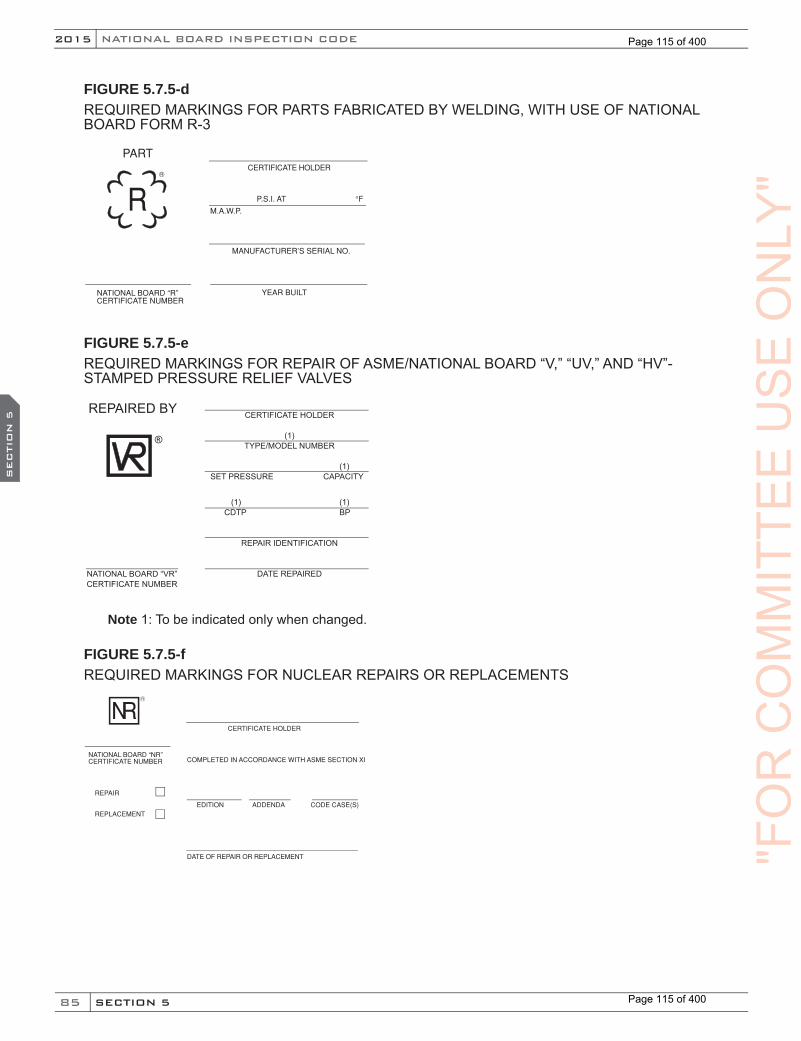
85
NATIONAL BOARD INSPECTION CODE2015
SECTION 5
SEC
TIO
N 5
FIGURE 5.7.5-dREQUIRED MARKINGS FOR PARTS FABRICATED BY WELDING, WITH USE OF NATIONAL BOARD FORM R-3
CERTIFICATE HOLDER
YEAR BUILTNATIONAL BOARD “R”CERTIFICATE NUMBER
M.A.W.P.
°FRR
PART
P.S.I. AT
MANUFACTURER’S SERIAL NO.
FIGURE 5.7.5-eREQUIRED MARKINGS FOR REPAIR OF ASME/NATIONAL BOARD “V,” “UV,” AND “HV”-STAMPED PRESSURE RELIEF VALVES
®
REPAIRED BY CERTIFICATE HOLDER
(1)TYPE/MODEL NUMBER
(1) SET PRESSURE CAPACITY
(1) (1) CDTP BP
REPAIR IDENTIFICATION
DATE REPAIREDNATIONAL BOARD “VR”CERTIFICATE NUMBER
Note 1: To be indicated only when changed.
FIGURE 5.7.5-fREQUIRED MARKINGS FOR NUCLEAR REPAIRS OR REPLACEMENTS
CERTIFICATE HOLDER
DATE OF REPAIR OR REPLACEMENT
NATIONAL BOARD “NR”CERTIFICATE NUMBER COMPLETED IN ACCORDANCE WITH ASME SECTION XI
EDITION ADDENDA CODE CASE(S)
REPAIR
REPLACEMENT
R
NR
"FO
RC
OM
MIT
TEE
US
EO
NLY
"
Page 115 of 400
Page 115 of 400
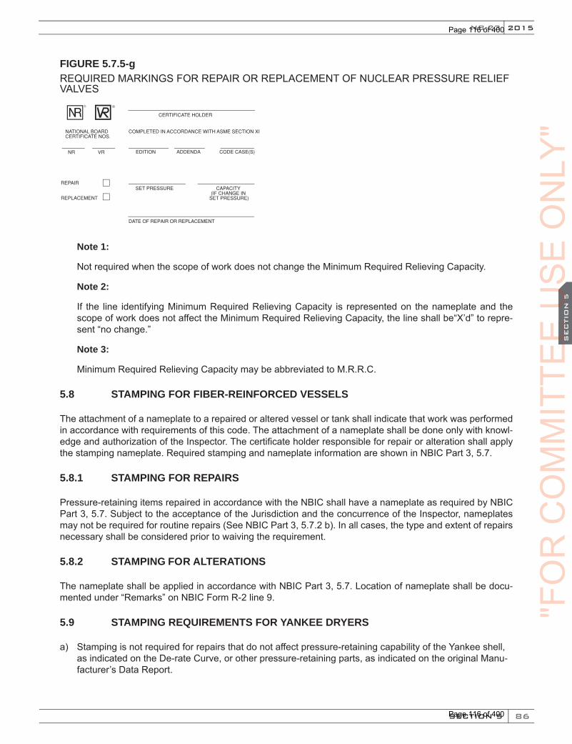
86
2015
SECTION 5
SEC
TIO
N 5
NB-23
FIGURE 5.7.5-gREQUIRED MARKINGS FOR REPAIR OR REPLACEMENT OF NUCLEAR PRESSURE RELIEF VALVES
CERTIFICATE HOLDER
DATE OF REPAIR OR REPLACEMENT
NATIONAL BOARDCERTIFICATE NOS.
COMPLETED IN ACCORDANCE WITH ASME SECTION XI
EDITION ADDENDA CODE CASE(S)
REPAIR
REPLACEMENT
®
NR VR
SET PRESSURE CAPACITY(IF CHANGE IN
SET PRESSURE)
R
NR
Note 1:
Not required when the scope of work does not change the Minimum Required Relieving Capacity.
Note 2:
If the line identifying Minimum Required Relieving Capacity is represented on the nameplate and the scope of work does not affect the Minimum Required Relieving Capacity, the line shall be“X’d” to repre-sent “no change.”
Note 3:
Minimum Required Relieving Capacity may be abbreviated to M.R.R.C.
5.8 STAMPING FOR FIBER-REINFORCED VESSELS
The attachment of a nameplate to a repaired or altered vessel or tank shall indicate that work was performed in accordance with requirements of this code. The attachment of a nameplate shall be done only with knowl-edge and authorization of the Inspector. The certificate holder responsible for repair or alteration shall apply the stamping nameplate. Required stamping and nameplate information are shown in NBIC Part 3, 5.7.
5.8.1 STAMPING FOR REPAIRS
Pressure-retaining items repaired in accordance with the NBIC shall have a nameplate as required by NBIC Part 3, 5.7. Subject to the acceptance of the Jurisdiction and the concurrence of the Inspector, nameplates may not be required for routine repairs (See NBIC Part 3, 5.7.2 b). In all cases, the type and extent of repairs necessary shall be considered prior to waiving the requirement.
5.8.2 STAMPING FOR ALTERATIONS
The nameplate shall be applied in accordance with NBIC Part 3, 5.7. Location of nameplate shall be docu-mented under “Remarks” on NBIC Form R-2 line 9.
5.9 STAMPING REQUIREMENTS FOR YANKEE DRYERS
a) Stamping is not required for repairs that do not affect pressure-retaining capability of the Yankee shell, as indicated on the De-rate Curve, or other pressure-retaining parts, as indicated on the original Manu-facturer’s Data Report.
"FO
RC
OM
MIT
TEE
CO
MM
ITTE
EC
OM
MIT
TEE SECT
ION
5C
OM
MIT
TEE SECT
ION
5US
EU
SE
US
ES
EC
TIO
N 5US
ES
EC
TIO
N 5
ON
LY"
Page 116 of 400
Page 116 of 400
87
NATIONAL BOARD INSPECTION CODE2015
SECTION 5
SEC
TIO
N 5
b) Stamping is required for repairs that affect pressure-retaining capability of the Yankee Dryer shell, as indicated on the De-rate Curve, or other pressure-retaining parts as indicated on the original Manufac-turer’s Data Report.
c) Stamping is required for alterations as listed in NBIC Part 3, S5.7.2.
d) Stamping, when required, shall meet the requirements for stamping in NBIC Part 3, 5.7.2. The location of stamping shall be described in the “Remarks” section of Form R-2.
5.10 ALTERNATIVE MARKING AND STAMPING FOR GRAPHITE PRESSURE EQUIPMENT
a) General Requirements
1) This procedure may be used in lieu of the stamping and nameplate requirements defined in this section.
2) The required data as defined in this section shall be 5/32 in. (4 mm) high, minimum.
3) The National Board Code Symbol “R” shall be used to make the impression in the cement.
b) Application of the “R” Code Symbol
1) The graphite surface shall be clean and smooth.
2) Apply a thin coating of cement onto the code part. The cement should have the consistency of toothpaste.
3) Apply sufficient heat to the cement so that it begins to form a skin.
4) Apply a coating of a thinned release agent, such as “anti-seize,” to the tip of the “R” stamp with a brush.
5) Press the coated stamp all the way to the bottom of the cement and remove by pulling straight out before the cement hardens.
6) Cure or heat the impression as required.
7) When cured, the part may be washed to remove any excess release agent.
c) Application of characters directly to graphite
1) Use a very thin template of a flexible material (stainless steel; flexible and easily cleaned).
2) Place the template over a clean smooth surface.
3) Hold the template securely and trowel over with approved cement to fill all of the template area.
4) Carefully lift the template from the graphite part and examine the detail of the characters.
5) If acceptable, cure the cement.
6) If the characters are incorrect or damaged, wipe off the cement with a compatible solvent and reapply.
Note: The preceding methods can be applied jointly to identify the graphite part and to transfer the “R” stamp.
"FO
RC
OM
MIT
TEE
US
EO
NLY
"
Page 117 of 400
Page 117 of 400
88
2015
SECTION 5
SEC
TIO
N 5
NB-23
5.11 REMOVAL OF ORIGINAL STAMPING OR NAMEPLATE
If it becomes necessary to remove original stamping, the Inspector shall, subject to the approval of the Juris-diction, witness making of a facsimile of stamping, the obliteration of old stamping, and transfer of stamping to the new item. When stamping is on a nameplate, the Inspector shall witness transfer of nameplate to the new location. Any relocation shall be described on the applicable NBIC “R” Form. The re-stamping or replacement of a code symbol stamp shall be performed only as permitted by the governing code of construction.
5.12 STAMPING REQUIREMENTS FOR PRESSURE RELIEF DEVICES
5.12.1 NAMEPLATES
Proper marking and identification of tested or repaired valves is critical to ensuring acceptance during sub-sequent inspections, and also provide for traceability and identification of any changes made to the valve. All operations that require the valve’s seals to be replaced shall be identified by a nameplate as described in NBIC Part 3, 5.12.2 or 5.12.4.
5.12.2 REPAIR NAMEPLATE
When a pressure relief valve is repaired, a metal repair nameplate stamped with the information required below shall be securely attached to the valve adjacent to the original manufacturer’s stamping or nameplate. If not mounted directly on the valve, the nameplate shall be securely attached so as not to interfere with valve operation and sealed in accordance with the quality system.
a) Prior to attachment of the repair nameplate, the previous repair nameplate, if applicable, shall be re-moved from the repaired valve.
b) As a minimum, the information on the valve repair nameplate (see NBIC Part 3, Figure 5.7.5-e) shall include:
1) The name of the repair organization preceded by the words “repaired by;”
2) The “VR” repair symbol stamp and the “VR” certificate number;
3) Unique identifier (e.g., repair serial number, shop order number, etc.);
4) Date of repair;
5) Set pressure;
6) Capacity and capacity units (if changed from original nameplate due to set pressure or service fluid change);
7) Type/Model number (if changed from original nameplate by a conversion. See NBIC Part 3, S7.2); and
8) When an adjustment is made to correct for service conditions of superimposed back pressure and/or temperature or the differential between popping pressure between steam and air (see NBIC Part 3, 4.5.2), the information on the valve repair nameplate shall include the:
a. Cold Differential Test Pressure (CDTP); and
b. Superimposed Back Pressure (BP) (only when applicable).
"FO
RC
OM
MIT
TEE
CO
MM
ITTE
EC
OM
MIT
TEE SECT
ION
5C
OM
MIT
TEE SECT
ION
5US
EU
SE
US
ES
EC
TIO
N 5US
ES
EC
TIO
N 5
ON
LY"
Page 118 of 400
Page 118 of 400
89
NATIONAL BOARD INSPECTION CODE2015
SECTION 5
SEC
TIO
N 5
5.12.3 CHANGES TO ORIGINAL PRESSURE RELIEF VALVE NAMEPLATE INFORMATION
a) If the set pressure is changed, the set pressure, capacity, and blowdown, if applicable, on the original nameplate or stamping shall be marked out, but left legible. The new capacity shall be based on that for which the valve was originally certified.
b) If service fluid is changed, the capacity, including units, on the original nameplate or stamping shall be marked out, but left legible. The new capacity shall be based on that for which the valve was originally certified, or if a conversion has been made, as described in NBIC Part 3, S7.2 on the capacity certifica-tion for the valve as converted.
c) If the Type/Model number is changed, the Type/Model number on the original nameplate shall be marked out, but left legible.
d) If the blowdown is changed, the blowdown on the original nameplate or stamping shall be marked out, but left legible. The new blowdown may be based on the current ASME Code requirements.
e) Incorrect information on the original manufacturer’s nameplate shall be marked out, but left legible. Cor-rected information shall be indicated on the repair nameplate and noted on the document as required by the quality system.
5.12.4 TEST ONLY NAMEPLATE
a) Where a valve has been tested and adjusted to restore the nameplate set pressure , as permitted by NBIC Part 3, S7.10.1, but not otherwise repaired, a “Test Only” nameplate shall be applied that contains the following information:
1) Name of responsible organization;
2) Date of test;
3) Set Pressure; and
4) Identification, such as “Test Only.”
b) A “Test Only” nameplate is also recommended when periodic testing has been performed, even when no adjustments have been made, for the purpose of identifying the date the valve was tested.
c) The existing repair nameplates, if applicable, shall not be removed during such testing.
5.12.5 REPLACEMENT OF ILLEGIBLE OR MISSING NAMEPLATES
a) Illegible Nameplates
When information on the original manufacturer’s or assembler’s nameplate or stamping is illegible, but traceability can be confirmed, the nameplate or stamping will be augmented by a nameplate furnished by the “VR” Stamp Holder stamped “Duplicate.” It shall contain all information that originally appeared on the nameplate or valve, as required by the applicable section of the ASME Code, except the “V,” “HV,” or “UV” symbol and the National Board mark. The repair organization’s nameplate, with the “VR” stamp and other required data specified in NBIC Part 3, 5.12.2, will make the repairer responsible to the owner and the Jurisdiction that the information on the duplicate nameplate is correct.
b) Missing Nameplates
When the original valve nameplate is missing, the repair organization is not authorized to perform repairs to the valve under the “VR” program, unless positive identification can be made to that specific valve and
"FO
RC
OM
MIT
TEE
US
EO
NLY
"
Page 119 of 400
Page 119 of 400

90
2015
SECTION 5
SEC
TIO
N 5
NB-23
verification that the valve was originally stamped with an ASME “V” or “UV” symbol or marked with an ASME “HV” symbol. Valves that can be positively identified will be equipped with a duplicate nameplate, as described in this section, in addition to the repairer’s “VR”-stamped nameplate. The repairer’s respon-sibilities for accurate data, as defined in NBIC Part 3, 5.12.5 a) shall apply.
c) Marking of Original Code Stamp
When a duplicate nameplate is affixed to a valve, as required by this section, it shall be marked “Sec. I,” “Sec. IV,” or “Sec. VIII,” as applicable, to indicate the original ASME Code stamping.
5.13 REPAIR AND ALTERATION FORMS AND INSTRUCTIONS FOR COMPLETING FORMS
The following forms may be used for documenting specific requirements as indicated on the top of each form.
5.13.1 FORM R-1, REPORT OF REPAIR, see Pg. 97
5.13.2 FORM R-2, REPORT OF ALTERATIONS, see Pg. 98
5.13.3 FORM R-3, REPORT OF PARTS FABRICATED BY WELDING, see Pg. 99
5.13.4 FORM R-4, REPORT SUPPLEMENTARY SHEET, see Pg. 101
5.13.4.1 INSTRUCTIONS FOR COMPLETING NATIONAL BOARD FORM “R” REPORTS
These instructions are to be used when completing the National Board Form “R” Reports. When computer generated, the format of the form shall replicate the type and relative location of the information depicted on the Form “R” Reports shown in NBIC Part 3, 5.13.1 through 5.13.4.
1) The name and address of the “R” Certificate Holder performing the work as it appears on the “Certifi-cate of Authorization”. On a Form R-2, the organization that performed the design work will complete line 1a) and the organization completing the construction activities will complete line 1b).
2) When registering a Form “R” Report with the National Board, this line is solely designated for a unique sequential number assigned by the “R” Certificate Holder. When the “R” Form is not to be registered, indicate so by “N/A”. As described in NBIC Part 3,5.6, a log shall be maintained identifying sequentially, any Form “R” registered with the National Board. For re-rating only, the Design Organization registers the Form R-2. Where physical work is also performed, the Construction Organization registers the Form R-2.
3) Name and address of the owner of the pressure-retaining item.
4) Name and address of plant or facility where the pressure-retaining item is installed.
5) Description of the pressure-retaining item, such as boiler or pressure vessel, or piping. Include the applicable unit identification.
6) Name of the original manufacturer of the pressure-retaining item. If the original manufacturer is un-known, indicate by, “unknown.”
7) Document the serial number of the pressure-retaining item if assigned by the original manufacturer. If there is no serial number assigned or is unknown, indicate “unknown.”
"FO
RC
OM
MIT
TEE
CO
MM
ITTE
EC
OM
MIT
TEE SECT
ION
5C
OM
MIT
TEE SECT
ION
5US
EU
SE
US
ES
EC
TIO
N 5US
ES
EC
TIO
N 5
ON
LY"
Page 120 of 400
Page 120 of 400
91
NATIONAL BOARD INSPECTION CODE2015
SECTION 5
SEC
TIO
N 5
8) When the pressure-retaining item is registered with the National Board, document the applicable regis-tration number. If the pressure-retaining item is installed in Canada, indicate the Canadian design regis-tration number (CRN), and list the drawing number under “other.” If the item is not registered, indicate, “none.”
9) Identify the year in which fabrication/construction of the item was completed.
10) Indicate edition and addenda of the NBIC under which this work is being performed.
11) Indicate the name, section, division, edition, and addenda of the original code of construction for the pressure-retaining item. Also indicate the name, section, division, edition, and addenda of the construc-tion code used for the work being performed. If code cases are used, they shall be identified in the “Remarks” section.
12) Provide a detailed summary describing the scope of work that was completed to a pressure retaining item (PRI). The information to be considered when describing the scope of work should include such items as, the nature of the repair or alteration (i.e. welding, bonding, cementing), the specific location of the work performed to the PRI, the steps taken to remove a defect or as allowed by 3.3.4.8 to remain in place, the method of repair or alteration described as listed in the examples of Part 3, Section 3 or supplemental section if applicable, and the acceptance testing and or examination method used in accordance with the NBIC. When additional space is needed to describe the scope of work, a Form R-4 shall be used and attached. Information determined to be of a proprietary nature need not be included, but shall be stated on the form.
13) Indicate test pressure applied.
14) As applicable, identify what parts manufactured by welding or bonding were introduced as needed to complete the scope of work. Indicate part, item number, manufacturer’s name, stamped identification, and data report type or Certificate of Compliance.
15) Indicate any additional information pertaining to the work involved (e.g., routine repairs, code cases). For Form R-3, the part manufacturer is to indicate the extent he has performed any or all of the design function. If only a portion of the design, state which portion.
16) Type or print name of authorized representative of the “R” Certificate Holder attesting to accuracy of the work described.
17) Indicate National Board “R” Certificate or Authorization number.
18) Indicate month, day, and year that the “R” certificate expires.
19) Enter date certified.
20) Record name of “R” Certificate Holder who performed the described work, using full name as shown on the Certificate of Authorization or an abbreviation acceptable to the National Board.
21) Signature of authorized representative.
22) Type or print name of Inspector.
23) Indicate Inspector’s Jurisdiction.
24) Indicate Inspector’s employer.
25) Indicate address of Inspector’s employer (city and state or province).
26) Indicate month, day, and year of inspection by Inspector. In case of routine repairs this shall be the month, day, and year the Inspector reviews the completed routine repair package.
"FO
RC
OM
MIT
TEE
US
EO
NLY
"
Page 121 of 400
Page 121 of 400
92
2015
SECTION 5
SEC
TIO
N 5
NB-23
27) Signature of Inspector.
28) National Board commission number of Inspector, and when required by the Jurisdiction, the applicable State or Provincial numbers.
29) Document name and address of organization that purchased the parts for incorporation into the repair or alteration. If the part’s origin is unknown or the part was built for stock, so state.
30) Document name of organization responsible for specifying the code design conditions, if known. If origin of design conditions are unknown, state “unknown.”
31) Document name of organization responsible for performing the code design, if known. If code design organization is unknown, state “unknown.”
32) Name, section, and division of the design code, if known. If the design is unknown, state “unknown”
33) Indicate code edition year used for fabrication.
34) Indicate code addenda date used for fabrication.
35) Indicate the code paragraph reference for formula used to establish the MAWP, if known. If the code reference of the formula is unknown, state “unknown.”
36) If available, identify component by part’s original name, function, or use the original equipment manu-facturer’s “mark or item number.”
37) Indicate quantity of named parts.
38) Match line number references for identification of parts and description of parts.
39) Indicate manufacturer’s serial number for the named part.
40) Indicate drawing number for the named part.
41) Indicate maximum allowable working pressure for the part, if known.
42) Use inside diameter for size: indicate shape as square, round, etc.
43) Indicate the complete material specification number and grade.
44) Indicate nominal thickness of plate and minimum thickness after forming.
45) Indicate shape as flat, dished, ellipsoidal, or hemispherical.
46) Indicate minimum thickness after forming.
47) Indicate outside diameter.
48) Indicate minimum thickness of tubes.
49) Complete information identical to that shown on the Form “R” to which this sheet is supplementary.
50) Indicate the Form “R” type. Example: Form R-1, Form R-2, Form R-3.
51) Indicate the reference line number from the Form R to which this sheet is supplementary.
52) Complete information for which there was insufficient space on the reference Form “R”.
53) If applicable, document the unique purchase order, job, or tracking number, assigned by organization performing work.
"FO
RC
OM
MIT
TEE
CO
MM
ITTE
EC
OM
MIT
TEE SECT
ION
5C
OM
MIT
TEE SECT
ION
5US
EU
SE
US
ES
EC
TIO
N 5US
ES
EC
TIO
N 5
ON
LY"
Page 122 of 400
Page 122 of 400
93
NATIONAL BOARD INSPECTION CODE2015
SECTION 5
SEC
TIO
N 5
54) Indicate the maximum allowable working pressure of the pressure-retaining item.
55) Indicate the type of repair, e.g., welded, graphite pressure equipment, or fiber-reinforced plastic pres-sure equipment.
5.13.5 FORM NR-1, NUCLEAR COMPONENTS AND SYSTEMS IN NUCLEAR POWER PLANTS see Pg. 102
5.13.5.1 GUIDE FOR COMPLETING NATIONAL BOARD FORM NR-1 REPORTS
Title Block: Check Category of Activity: 1, 2, or 3
Check type of activity, repair, replacement, alteration/modification, and/or re-rating, as applicable.
1) Name and address of the organization, as shown on the National Board “NR” Certificate of Authoriza-tion, which performed the activity.
2) Indicate “NR” Form Registration Number.
3) Indicate the purchase order number, job number, etc., as applicable, assigned by the organization that performed the work.
4) Name and address of the owner of the nuclear power plant.
5) Name and address of the nuclear power plant and, if applicable, identification of the unit.
6) Identify the system (e.g., residual heat removal, reactor coolant) with which the repair, replacement, alteration/modification, or rerating activity is associated.
7) ASME Code Section XI or Section III, as applicable to the repairs, alterations/modification, replacement or rerating activity performed.
8) Name of the organization, as shown on the Certificate of Authorization, which performed the design activity including:
a. Original Design Specification Number and Revision Number.
b. Original Design Report Number and Revision Number.
c. Revised Design Specification Number and Revision Number.
d. Revised Design Report Number and Revision Number.
e. Design Reconciliation Number and Revision Number.
f. Applicable Code Edition and Addenda Date(s).
9) Check the type of test conducted (e.g., hydrostatic, pneumatic, system leakage, exempt, or other) and indicated the pressure applied when applicable.
10) Sequential number assigned to each item reported.
11) Indicate the type of component (e.g., vessel, line valve, pump, piping system).
12) Manufacturer’s name of the affected item.
13) Manufacturer’s serial number.
14) National Board number, if applicable, of the affected item.
(15)
"FO
RC
OM
MIT
TEE
US
EO
NLY
"
Page 123 of 400
Page 123 of 400
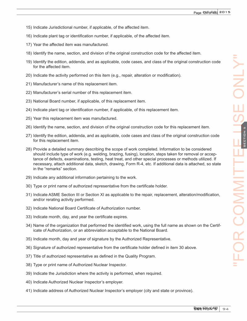
94
2015
SECTION 5
SEC
TIO
N 5
NB-23
15) Indicate Jurisdictional number, if applicable, of the affected item.
16) Indicate plant tag or identification number, if applicable, of the affected item.
17) Year the affected item was manufactured.
18) Identify the name, section, and division of the original construction code for the affected item.
19) Identify the edition, addenda, and as applicable, code cases, and class of the original construction code for the affected item.
20) Indicate the activity performed on this item (e.g., repair, alteration or modification).
21) Manufacturer’s name of this replacement item.
22) Manufacturer’s serial number of this replacement item.
23) National Board number, if applicable, of this replacement item.
24) Indicate plant tag or identification number, if applicable, of this replacement item.
25) Year this replacement item was manufactured.
26) Identify the name, section, and division of the original construction code for this replacement item.
27) Identify the edition, addenda, and as applicable, code cases and class of the original construction code for this replacement item.
28) Provide a detailed summary describing the scope of work completed. Information to be considered should include type of work (e.g. welding, brazing, fusing), location, steps taken for removal or accep-tance of defects, examinations, testing, heat treat, and other special processes or methods utilized. If necessary, attach additional data, sketch, drawing, Form R-4, etc. If additional data is attached, so state in the “remarks” section.
29) Indicate any additional information pertaining to the work.
30) Type or print name of authorized representative from the certificate holder.
31) Indicate ASME Section III or Section XI as applicable to the repair, replacement, alteration/modification, and/or rerating activity performed.
32) Indicate National Board Certificate of Authorization number.
33) Indicate month, day, and year the certificate expires.
34) Name of the organization that performed the identified work, using the full name as shown on the Certif-icate of Authorization, or an abbreviation acceptable to the National Board.
35) Indicate month, day and year of signature by the Authorized Representative.
36) Signature of authorized representative from the certificate holder defined in item 30 above.
37) Title of authorized representative as defined in the Quality Program.
38) Type or print name of Authorized Nuclear Inspector.
39) Indicate the Jurisdiction where the activity is performed, when required.
40) Indicate Authorized Nuclear Inspector’s employer.
41) Indicate address of Authorized Nuclear Inspector’s employer (city and state or province).
"FO
RC
OM
MIT
TEE
CO
MM
ITTE
EC
OM
MIT
TEE SECT
ION
5C
OM
MIT
TEE SECT
ION
5US
EU
SE
US
ES
EC
TIO
N 5US
ES
EC
TIO
N 5
ON
LY"
Page 124 of 400
Page 124 of 400
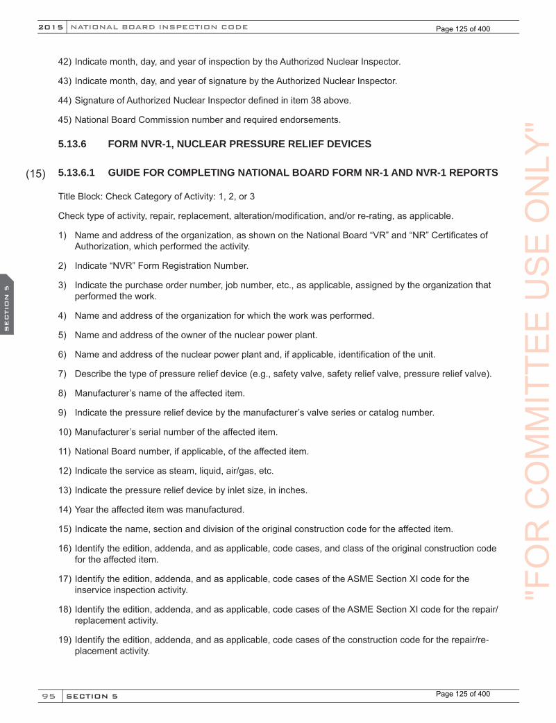
95
NATIONAL BOARD INSPECTION CODE2015
SECTION 5
SEC
TIO
N 5
42) Indicate month, day, and year of inspection by the Authorized Nuclear Inspector.
43) Indicate month, day, and year of signature by the Authorized Nuclear Inspector.
44) Signature of Authorized Nuclear Inspector defined in item 38 above.
45) National Board Commission number and required endorsements.
5.13.6 FORM NVR-1, NUCLEAR PRESSURE RELIEF DEVICES
5.13.6.1 GUIDE FOR COMPLETING NATIONAL BOARD FORM NR-1 AND NVR-1 REPORTS
Title Block: Check Category of Activity: 1, 2, or 3
Check type of activity, repair, replacement, alteration/modification, and/or re-rating, as applicable.
1) Name and address of the organization, as shown on the National Board “VR” and “NR” Certificates of Authorization, which performed the activity.
2) Indicate “NVR” Form Registration Number.
3) Indicate the purchase order number, job number, etc., as applicable, assigned by the organization that performed the work.
4) Name and address of the organization for which the work was performed.
5) Name and address of the owner of the nuclear power plant.
6) Name and address of the nuclear power plant and, if applicable, identification of the unit.
7) Describe the type of pressure relief device (e.g., safety valve, safety relief valve, pressure relief valve).
8) Manufacturer’s name of the affected item.
9) Indicate the pressure relief device by the manufacturer’s valve series or catalog number.
10) Manufacturer’s serial number of the affected item.
11) National Board number, if applicable, of the affected item.
12) Indicate the service as steam, liquid, air/gas, etc.
13) Indicate the pressure relief device by inlet size, in inches.
14) Year the affected item was manufactured.
15) Indicate the name, section and division of the original construction code for the affected item.
16) Identify the edition, addenda, and as applicable, code cases, and class of the original construction code for the affected item.
17) Identify the edition, addenda, and as applicable, code cases of the ASME Section XI code for the inservice inspection activity.
18) Identify the edition, addenda, and as applicable, code cases of the ASME Section XI code for the repair/replacement activity.
19) Identify the edition, addenda, and as applicable, code cases of the construction code for the repair/re-placement activity.
(15)
"FO
RC
OM
MIT
TEE
US
EO
NLY
"
Page 125 of 400
Page 125 of 400
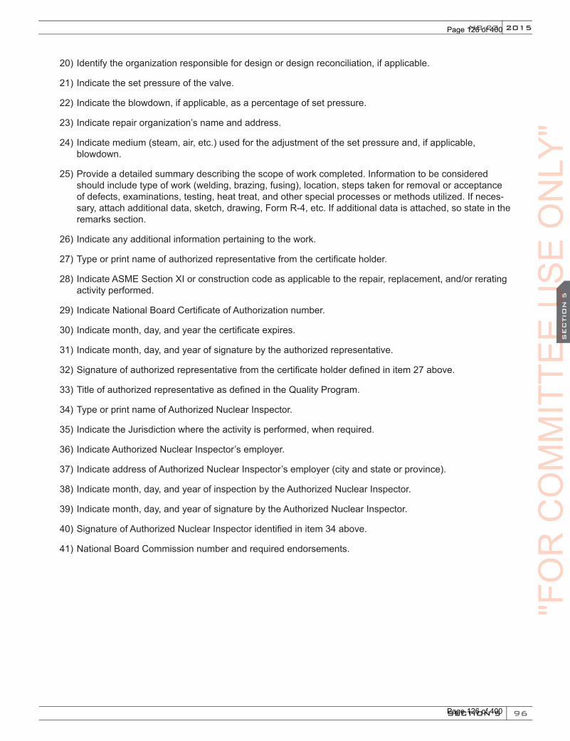
96
2015
SECTION 5
SEC
TIO
N 5
NB-23
20) Identify the organization responsible for design or design reconciliation, if applicable.
21) Indicate the set pressure of the valve.
22) Indicate the blowdown, if applicable, as a percentage of set pressure.
23) Indicate repair organization’s name and address.
24) Indicate medium (steam, air, etc.) used for the adjustment of the set pressure and, if applicable, blowdown.
25) Provide a detailed summary describing the scope of work completed. Information to be considered should include type of work (welding, brazing, fusing), location, steps taken for removal or acceptance of defects, examinations, testing, heat treat, and other special processes or methods utilized. If neces-sary, attach additional data, sketch, drawing, Form R-4, etc. If additional data is attached, so state in the remarks section.
26) Indicate any additional information pertaining to the work.
27) Type or print name of authorized representative from the certificate holder.
28) Indicate ASME Section XI or construction code as applicable to the repair, replacement, and/or rerating activity performed.
29) Indicate National Board Certificate of Authorization number.
30) Indicate month, day, and year the certificate expires.
31) Indicate month, day, and year of signature by the authorized representative.
32) Signature of authorized representative from the certificate holder defined in item 27 above.
33) Title of authorized representative as defined in the Quality Program.
34) Type or print name of Authorized Nuclear Inspector.
35) Indicate the Jurisdiction where the activity is performed, when required.
36) Indicate Authorized Nuclear Inspector’s employer.
37) Indicate address of Authorized Nuclear Inspector’s employer (city and state or province).
38) Indicate month, day, and year of inspection by the Authorized Nuclear Inspector.
39) Indicate month, day, and year of signature by the Authorized Nuclear Inspector.
40) Signature of Authorized Nuclear Inspector identified in item 34 above.
41) National Board Commission number and required endorsements."F
OR
CO
MM
ITTE
EC
OM
MIT
TEE
CO
MM
ITTE
E SECTIO
N 5
CO
MM
ITTE
E SECTIO
N 5US
EU
SE
US
ES
EC
TIO
N 5US
ES
EC
TIO
N 5
ON
LY"
Page 126 of 400
Page 126 of 400
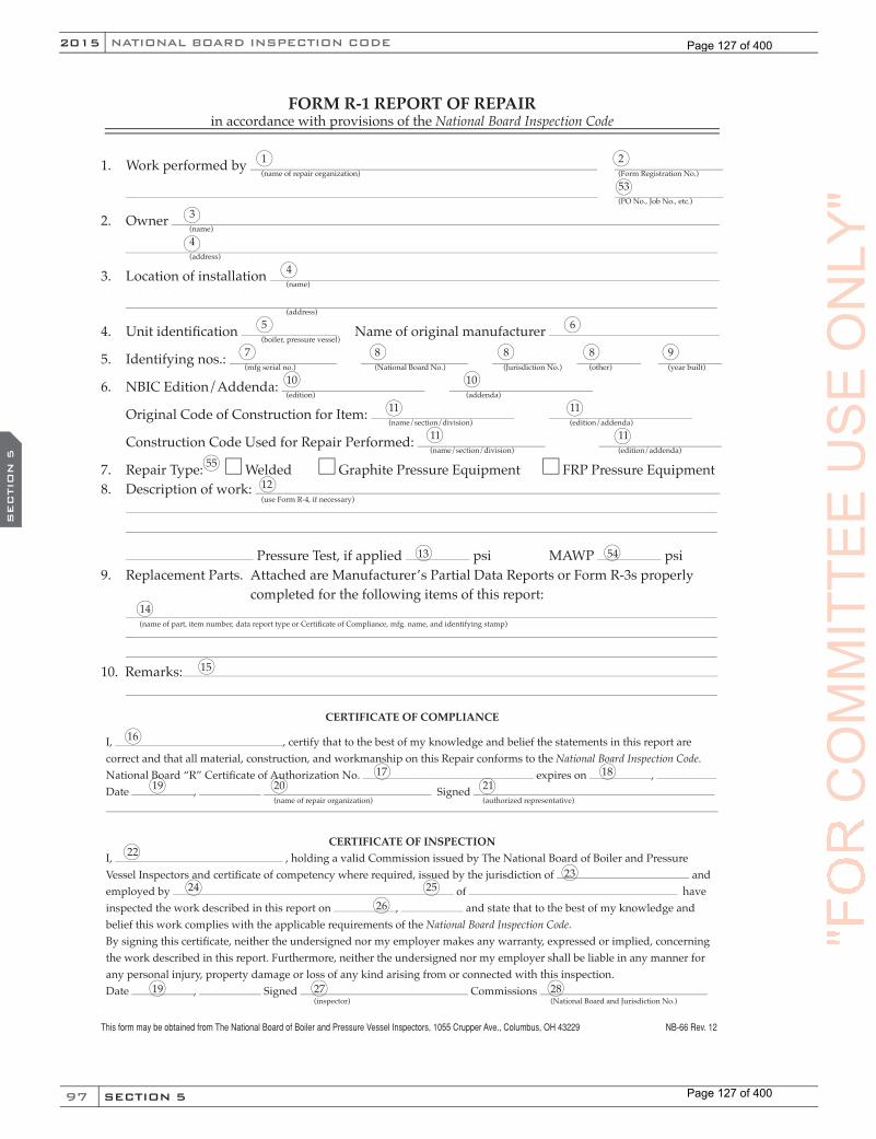
97
NATIONAL BOARD INSPECTION CODE2015
SECTION 5
SEC
TIO
N 5
FORM R-1 REPORT OF REPAIRin accordance with provisions of the National Board Inspection Code
1. Work performed by
2. Owner
3. Location of installation
4. Unit identifi cation Name of original manufacturer
5. Identifying nos.:
6. NBIC Edition/Addenda:
Original Code of Construction for Item:
Construction Code Used for Repair Performed:
7. Repair Type: Welded Graphite Pressure Equipment FRP Pressure Equipment8. Description of work:
Pressure Test, if applied psi MAWP psi9. Replacement Parts. Attached are Manufacturer’s Partial Data Reports or Form R-3s properly completed for the following items of this report: 10. Remarks:
CERTIFICATE OF COMPLIANCE
I, , certify that to the best of my knowledge and belief the statements in this report are correct and that all material, construction, and workmanship on this Repair conforms to the National Board Inspection Code.National Board “R” Certifi cate of Authorization No. expires on , Date , Signed
CERTIFICATE OF INSPECTIONI, , holding a valid Commission issued by The National Board of Boiler and Pressure Vessel Inspectors and certifi cate of competency where required, issued by the jurisdiction of and employed by of have inspected the work described in this report on , and state that to the best of my knowledge and belief this work complies with the applicable requirements of the National Board Inspection Code.By signing this certifi cate, neither the undersigned nor my employer makes any warranty, expressed or implied, concerning the work described in this report. Furthermore, neither the undersigned nor my employer shall be liable in any manner for any personal injury, property damage or loss of any kind arising from or connected with this inspection.Date , Signed Commissions
1 2 (name of repair organization) (Form Registration No.)
53 (PO No., Job No., etc.)
3 (name)
4 (address)
4 (name)
(address)
5 6 (boiler, pressure vessel)
7 8 8 8 9 (mfg serial no.) (National Board No.) (Jurisdiction No.) (other) (year built)
10 10 (edition) (addenda)
11 11 (name/section/division) (edition/addenda)
11 11 (name/section/division) (edition/addenda)
55
12 (use Form R-4, if necessary)
13 54
14 (name of part, item number, data report type or Certifi cate of Compliance, mfg. name, and identifying stamp)
15
16
17 18 19 20 21 (name of repair organization) (authorized representative)
22
23 24 25 26
19 27 28 (inspector) (National Board and Jurisdiction No.)
This form may be obtained from The National Board of Boiler and Pressure Vessel Inspectors, 1055 Crupper Ave., Columbus, OH 43229 NB-66 Rev. 12
"FO
RC
OM
MIT
TEE
US
EO
NLY
"
Page 127 of 400
Page 127 of 400

98
2015
SECTION 5
SEC
TIO
N 5
NB-23
FORM R-2 REPORT OF ALTERATIONin accordance with provisions of the National Board Inspection Code
1a. Design performed by: (name of “R” organization responsible for design)
(address)
1b. Construction performed by: (name of “R” organization responsible for construction)
(address)
2. Owner of Pressure Retaining Item: (name)
(address)
3. Location of Installation: (name)
(address)
4. Item identifi cation: Name of original manufacturer: (boiler, pressure vessel, or piping)
5. Identifying nos: (mfg. serial no.) (National Board No.) (Jurisdiction No.) (other) (year built)
6. NBIC Edition / Addenda: (edition) (addenda)
Original Code of Construction for Item: (name / section / division) (edition / addenda)
Construction Code Used for Alteration Performed: (name / section / division) (edition / addenda)
7a. Description of Design Scope:
Form R -4, Report Supplementary Sheet is attached
7b. Description of Construction Scope:
Form R -4, Report Supplementary Sheet is attached
Pressure Test, if applied psi MAWP psi
8. Replacement Parts. Attached are Manufacturer’s Partial Data Reports or Form R-3’s properly completed for the following items of this report:
(name of part, item number, data report type or Certifi cate of Compliance, mfg’s. name and identifying stamp)
NB-229, Rev. 6, (03/25/13)
(Form “R” Registration no.)
(P.O. No., Job No., etc.)
"FO
RC
OM
MIT
TEE
CO
MM
ITTE
EC
OM
MIT
TEE SECT
ION
5C
OM
MIT
TEE SECT
ION
5US
EU
SE
US
ES
EC
TIO
N 5US
ES
EC
TIO
N 5
ON
LY"
Page 128 of 400
Page 128 of 400
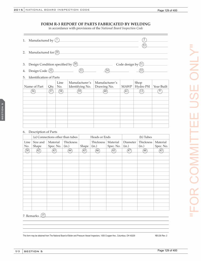
99
NATIONAL BOARD INSPECTION CODE2015
SECTION 5
SEC
TIO
N 5
FORM R-3 REPORT OF PARTS FABRICATED BY WELDINGin accordance with provisions of the National Board Inspection Code
1. Manufactured by
2. Manufactured for
3. Design Condition specifi ed by Code design by
4. Design Code
5. Identifi cation of Parts
Name of Part Qty.Line No.
Manufacturer’s Identifying No.
Manufacturer’s Drawing No. MAWP
ShopHydro PSI Year Built
6. Description of Parts(a) Connections other than tubes Heads or Ends (b) Tubes
Line No.
Size and Shape
Material Spec. No.
Thickness (in.) Shape
Thickness(in.)
Material Spec. No.
Diameter(in.)
Thickness(in.)
Material Spec. No.
7. Remarks
This form may be obtained from The National Board of Boiler and Pressure Vessel Inspectors, 1055 Crupper Ave., Columbus, OH 43229 NB-230 Rev. 2
1
29
2
53
30 31
32 33 34 35
36 37 38 39 40 41 13 9
38 42 43 44 45 46 43 47 48 43
15 "FO
RC
OM
MIT
TEE
US
EO
NLY
"
Page 129 of 400
Page 129 of 400
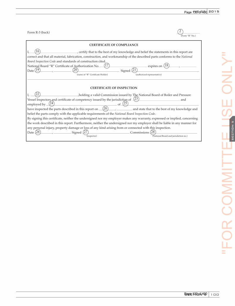
100
2015
SECTION 5
SEC
TIO
N 5
NB-23
Form R-3 (back)
CERTIFICATE OF COMPLIANCE
I, , certify that to the best of my knowledge and belief the statements in this report are correct and that all material, fabrication, construction, and workmanship of the described parts conforms to the National Board Inspection Code and standards of construction cited.National Board “R” Certifi cate of Authorization No. expires on , Date , Signed
CERTIFICATE OF INSPECTION
I, ,holding a valid Commission issued by The National Board of Boiler and Pressure Vessel Inspectors and certifi cate of competency issued by the jurisdiction of and employed by of have inspected the parts described in this report on , and state that to the best of my knowledge and belief the parts comply with the applicable requirements of the National Board Inspection Code.By signing this certifi cate, neither the undersigned nor my employer makes any warranty, expressed or implied, concerning the work described in this report. Furthermore, neither the undersigned nor my employer shall be liable in any manner for any personal injury, property damage or loss of any kind arising from or connected with this inspection.Date , Signed Commissions
(Form “R” No.)
(name of “R” Certifi cate Holder) (authorized representative)
(inspector) (National Board and jurisdiction no.)
16
2
19 20
22
26
17 1821
2325
2624
27 28
"FO
RC
OM
MIT
TEE
CO
MM
ITTE
EC
OM
MIT
TEE SECT
ION
5C
OM
MIT
TEE SECT
ION
5US
EU
SE
US
ES
EC
TIO
N 5US
ES
EC
TIO
N 5
ON
LY"
Page 130 of 400
Page 130 of 400

101
NATIONAL BOARD INSPECTION CODE2015
SECTION 5
SEC
TIO
N 5
FORM R-4 REPORT SUPPLEMENTARY SHEETin accordance with provisions of the National Board Inspection Code
1. Work performed by
2. Owner
3. Location of installation
ReferenceLine No. Continued from Form R–
Date , Signed Name
Date , Signed Commissions
This form may be obtained from The National Board of Boiler and Pressure Vessel Inspectors, 1055 Crupper Ave., Columbus, OH 43229 NB-231 Rev. 2
1 49 2 49 (name) (Form “R” referenced)
53 49 (address) (PO No., Job No., etc.)
3 or 29 49 (name)
(address)
(name)
(address)
50
51 52
19 21 20 49 (authorized representative) (authorized representative)
19 27 20 49 (inspector) (National Board and jurisdiction no.)
(15)
"FO
RC
OM
MIT
TEE
US
EO
NLY
"
Page 131 of 400
Page 131 of 400

102
2015
SECTION 5
SEC
TIO
N 5
NB-23
name of “NR” certifi cate holder PO no., job no., etc.
address
name
address
FORM NR–1 REPORT OF REPAIR OR REPLACEMENT TO NUCLEAR COMPONENTS AND SYSTEMS IN NUCLEAR POWER PLANTS
1. Work performed by
2. Owner
3. Name, address, and identifi cation of nuclear power plant
4. System
5a. Items that Required Repair or Replacement Activities
Identifi cation Construction Code Activity
No.Type of Item
Mfg. Name
Mfg. SerialNo.
Nat’l Bd No.
Juris.No. Other
Year Built
Name/Section/Division
Edition/Addenda
Code Case(s)
Code Class
Repair/Replace
1
2
3
4
5
6
7
8
9
10
11
12
5b. Items Installed During Replacement Activities
Identifi cation Construction Code
Type of Item
Installed or Replaced 5a Item No.
Mfg. Name
Mfg.Serial No.
Nat’l Bd No.
Juris.No. Other
Year Built
Name/Section/Division
Edition/Addenda
Code Case(s)
Code Class
6. ASME Code Section XI applicable for inservice inspection:
7. ASME Code Section XI used for repairs, modifi cations, or replacements:
8. Construction Code used for repairs or replacements:
9. Design responsibilities
10. Tests conducted: hydrostatic pneumatic design pressure pressure psi (MPa) Code Case(s)
This form may be obtained from The National Board of Boiler and Pressure Vessel Inspectors, 1055 Crupper Ave., Columbus, OH 43229 NB-81
1 2
4
5
6
8 9 11 12 15 16 17 18 19 19 19 20
10 21 22 23 24 25 26 27 28 29 29 29
30 30 30
31 31 31
32 32 32
33
34 34
"FO
RC
OM
MIT
TEE
CO
MM
ITTE
EC
OM
MIT
TEE SECT
ION
5C
OM
MIT
TEE SECT
ION
5US
EU
SE
US
ES
EC
TIO
N 5US
ES
EC
TIO
N 5
ON
LY"
Page 132 of 400
Page 132 of 400
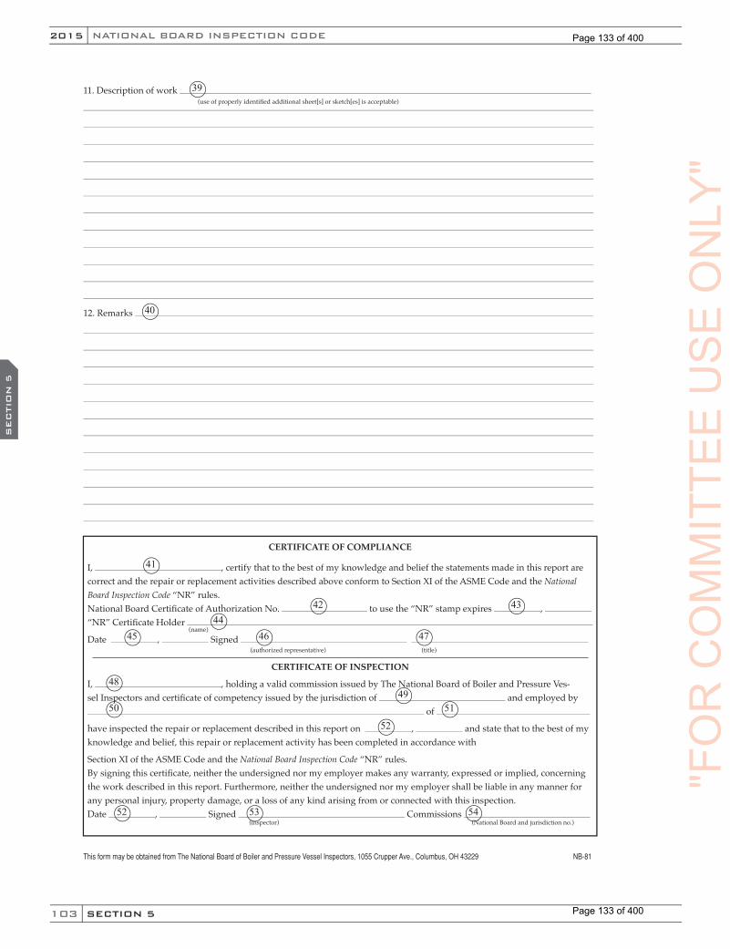
103
NATIONAL BOARD INSPECTION CODE2015
SECTION 5
SEC
TIO
N 5
11. Description of work
12. Remarks
CERTIFICATE OF COMPLIANCE
I, , certify that to the best of my knowledge and belief the statements made in this report are correct and the repair or replacement activities described above conform to Section XI of the ASME Code and the National Board Inspection Code “NR” rules.National Board Certifi cate of Authorization No. to use the “NR” stamp expires , “NR” Certifi cate Holder
Date , Signed
CERTIFICATE OF INSPECTION
I, , holding a valid commission issued by The National Board of Boiler and Pressure Ves-sel Inspectors and certifi cate of competency issued by the jurisdiction of and employed by
of
have inspected the repair or replacement described in this report on , and state that to the best of my knowledge and belief, this repair or replacement activity has been completed in accordance with
Section XI of the ASME Code and the National Board Inspection Code “NR” rules.By signing this certifi cate, neither the undersigned nor my employer makes any warranty, expressed or implied, concerning the work described in this report. Furthermore, neither the undersigned nor my employer shall be liable in any manner for any personal injury, property damage, or a loss of any kind arising from or connected with this inspection.Date , Signed Commissions
(use of properly identifi ed additional sheet[s] or sketch[es] is acceptable)
(name) (authorized representative) (title)
(inspector) (National Board and jurisdiction no.)
This form may be obtained from The National Board of Boiler and Pressure Vessel Inspectors, 1055 Crupper Ave., Columbus, OH 43229 NB-81
39
40
41
42 4344
45 46 47
4849
50 51
52
52 53 54
"FO
RC
OM
MIT
TEE
US
EO
NLY
"
Page 133 of 400
Page 133 of 400

104
2015
SECTION 6
SU
PPL. 1
NB-23
PART 3, SECTION 6 REPAIR AND ALTERATION SUPPLEMENTS
SUPPLEMENT 1 STEAM LOCOMOTIVE FIRETUBE BOILER REPAIRS
S1.1 SCOPE
This supplement applies to all boilers attached to steam locomotives operating on track gaged 24 in. (610 mm) or greater.
S1.1.1 FEDERAL RAILROAD ADMINISTRATION (FRA)
The FRA rules for steam locomotive boilers are published in the Code of Federal Regulations (CFR) 49CFR Part 230, dated November 17,1999.13 All locomotives under FRA jurisdiction are documented on FRA Form 4 as defined in 49CFR Part 230. This document is the formal documentation of the steam locomotive boiler and is required to be completed prior to the boiler being placed in service. This document shall be used as the data report for the boiler, applicable to all repairs and alterations performed. National Board “R” Certificate Holders shall document their repairs and/or alterations on National Board Forms R-1 or R-2. These reports shall be distributed to the owner-user of the boiler, who is required to incorporate them into a FRA Form 19, which becomes an attachment to the FRA Form 4. The design margin for all such repairs or alterations shall not be less than four, based on ultimate tensile strength of the material.
S1.1.2 REQUIREMENTS FOR WELDING ACTIVITIES
a) Before performing any welding activities, consideration shall be given to ensure the weldability of locomotive boiler materials.
b) Special jurisdictional approval may be required prior to starting welding activity on locomotive boilers.
S1.1.3 MATERIALS
a) The older steels used in riveted construction were frequently rimmed steels, high in carbon, sulfur, phosphorus and hydrogen. The older steels were not melted to a fine grain practice and will typically have poor toughness properties.
b) If welding is to be used to repair a pressure-retaining item that was manufactured using riveted construction, the repair organization should perform a chemical composition analysis on the steel plate base metal and rivet material to determine weldability. Specific quantities of carbon, manganese, sulfur, phosphorus, and aluminum shall be identified and included in the analysis. The result of the analysis shall be acceptable to the Inspector and Jurisdiction when required.
S1.1.3.1 MATERIAL LIST FOR STEAM LOCOMOTIVE BOILERS
Table S1.1.3.1 is intended as a basic guideline only and covers basic carbon steel and some alloy steel material specifications. Other alloy materials may be available for these applications if necessary.
a) SA-516 steel is recommended for firebox repairs. It is a fine grain steel that accepts flanging and bending with less tendency to crack than coarse grain steels such as SA-515 or SA-285 Grade C.
13 Steamlocomotiveinspectionandmaintenancestandards,whichisnowcodifiedat49CFRPart230,maybeobtainedattheFRAwebsite.
(15) "FO
R(15) "F
OR
(15)
CO
MM
ITTE
EC
OM
MIT
TEE
CO
MM
ITTE
ES
UPPL. 1
CO
MM
ITTE
ES
UPPL. 1
US
EO
NLY
"
Page 134 of 400
Page 134 of 400

105
NATIONAL BOARD INSPECTION CODE2015
SECTION 6
SU
PPL. 1
Coarse grain steels have, on occasion, been found to crack or split after complicated flanging, bending, and forming.
b) SA-36 shall not be used to make any pressure-retaining part such as shells, staybolt sleeves, or caps.
c) When rivets are made from SA-675, the finished rivets must meet the physical requirements of the original rivet specification or SA-31 Grade A or B.
d) When staybolt material tensile strength is greater than that of the firebox sheets, the firebox sheets deflect instead of the staybolts, which can result in the sheets developing cracks and leaking staybolts. In addition, high tensile strength steels are difficult to drive. Maximum allowable tensile strength shall be 7,500 psi (51.71 MPa).
TABLE S1.1.3.1
Application
Boiler Tubes & Flues, Arch Tubes Superheater Units
Specification
SA-178 Grade A, SA-192, SA-210
Boiler & Firebox Plate, Pressure Retaining Plate SA-285 Grade C, SA-515, SA-516, SA-203, SA-204
Welded Staybolts SA-675, SA-36, SA-31 Grade B
Threaded StayboltsSA-31 Grade A SA-675 with a tensile strength of 47,000 psi to 65,000 psi inclusive
Staybolt Sleeves and Caps SA-105 Forging, SA-675Boiler Braces SA-675, SA-36Rivets SA-675, SA-31Forged Parts & Fittings SA-105, SA-181
Pressure-Retaining Steel Castings SA-216, A-217
Hollow Cylindrical Pressure-Retaining Parts SA-105 Forgings, SA-675 Bar Stock
Superheater Unit Bolts & Nuts Bolts - SA-193, Nuts - SA-194Pipe Flanges SA-181, SA-105Bolts & Studs SA-307 Grades A&BPipe SA-106, SA-53 seamlessBronze Castings & Washout Plugs SB-61, SB-62, SB-148
"FO
RC
OM
MIT
TEE
US
EO
NLY
"
Page 135 of 400
Page 135 of 400
106
2015
SECTION 6
SU
PPL. 1
NB-23
S1.1.4 FORMULA AND CALCULATIONS FOR STEAM LOCOMOTIVE BOILERS
a) Most steam locomotive boilers were manufactured in the first half of the 20th century or before. The calculations, formula, and shop practices used are now distant history and quite difficult to obtain. The rules for riveted construction were last published by ASME in Section I Code, 1971 Edition.
b) This supplement herein, is based in part on the ASME Code, Section III, 1952 Edition,14 which was the last published edition of the Steam Locomotive Code. The railroad industry has attempted to collect the old formula and some shop practices. These have been published by The Engineering Standards Committee for Steam Locomotives, Inc. (ESC) as Compendium, Volume 1, Compilation of Calculations.15
S1.2 LOCOMOTIVE FIRETUBE BOILER REPAIRS
S1.2.1 REPAIR OF STAYBOLT HOLES
a) Staybolt holes may be repaired by welding, reaming, or retapping to a larger size or by installing a flush patch.
b) If the staybolt hole was threaded and is to be repaired by welding, the threads shall be removed prior to welding.
S1.2.2 THREADED STAYBOLTS
a) All threaded staybolts shall have either 11- or 12-thread pitch. Staybolt threads shall have a good close fit in sheets. Changing the staybolt thread pitch from 11 to 12 or the reverse shall be considered a repair.
b) All staybolts shorter than 8 in. (200 mm) in length shall have telltale holes. Staybolt telltale holes in existing staybolts shall be 3/16 in. (5 mm) to 7/32 in. (5.5 mm) in diameter and at least 1-1/4 in. (32 mm) deep in the outer end. When staybolts 8 in. (200 mm) or less in length are replaced, they shall be replaced with staybolts that have a telltale hole 3/16 in. (5 mm) to 7/32 in. (5.5 mm) in diameter their entire length, or with ones that have a 3/16 in. (5 mm) to 7/32 in. (5.5 mm) diameter hole in each end, drilled a minimum of 1-1/4 in. (32 mm) deep. On reduced body staybolts, the telltale hole shall extend beyond the fillet and into the reduced section of the staybolt. Ball socket-type flexible staybolts may have telltale holes that extend from the threaded end of the bolt into the bolt head for a distance of one-third the spherical bolt head diameter.
c) Telltale holes shall be reopened after driving and riveting heads.
d) Staybolt length shall be sized so the length of bolt projecting through the sheet is not less than 1/8 in. (3 mm) and is sufficient to produce a full head after driving and riveting the head.
e) The thread lead of both bolt ends and both firebox sheets shall be synchronized to permit the staybolt to be installed without stripping the threads.
f) When riveting staybolt heads, the bolt’s opposite end shall be bucked or braced to prevent damaging the staybolt’s threads. Bracing can be done several ways, such as using a pneumatic holder or a heavy steel bucking bar. Driving the heads on both ends of the staybolt simultaneously, using two pneumatic rivet hammers (double gunning), is acceptable. Staybolts are to be driven in such a manner as to expand radially the staybolt body and threads into the sheet prior to forming the head. Merely driving over the head is not acceptable.
14 ThiscodeisavailablefromtheNationalBoard.15 CopiesofThe Engineering Standards Committee for Steam Locomotives, Inc., Compendium, Volume 1, Compilation of Calculations, maybeobtainedfromtheStrasburgRailRoad,P.O.Box96,Strasburg,PA17579,717.687.8421.
"FO
RC
OM
MIT
TEE
CO
MM
ITTE
EC
OM
MIT
TEE
SU
PPL. 1
CO
MM
ITTE
ES
UPPL. 1
US
EO
NLY
"
Page 136 of 400
Page 136 of 400
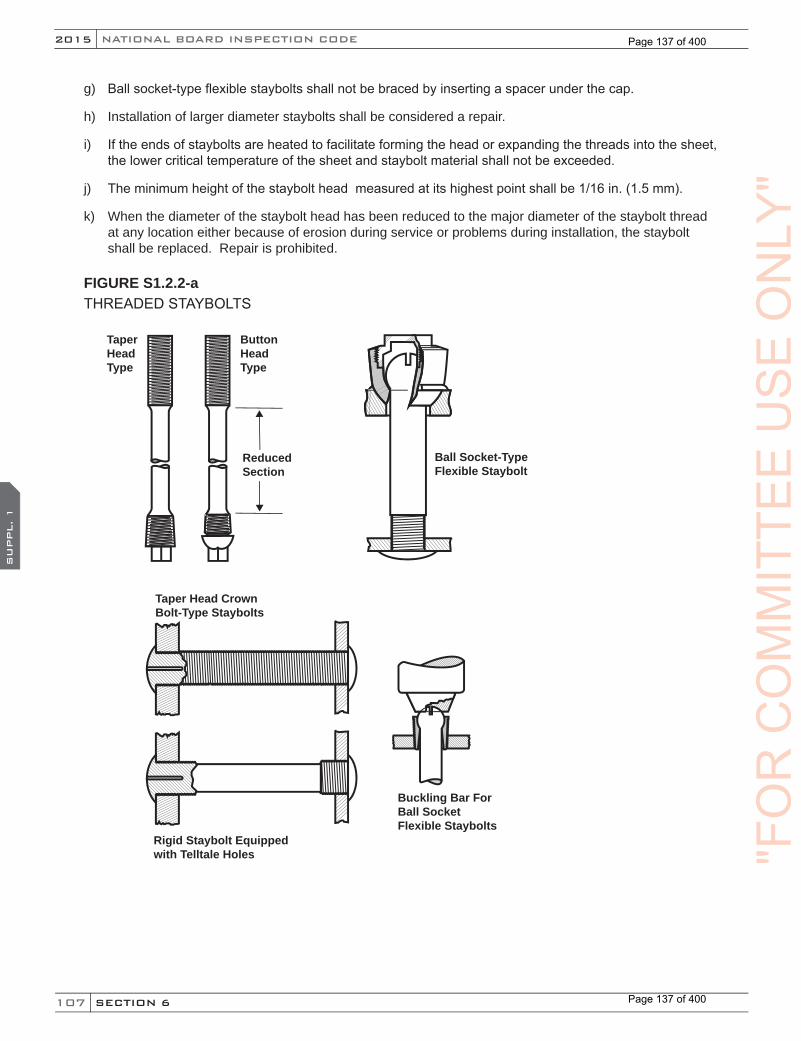
107
NATIONAL BOARD INSPECTION CODE2015
SECTION 6
SU
PPL. 1
g) Ball socket-type flexible staybolts shall not be braced by inserting a spacer under the cap.
h) Installation of larger diameter staybolts shall be considered a repair.
i) If the ends of staybolts are heated to facilitate forming the head or expanding the threads into the sheet, the lower critical temperature of the sheet and staybolt material shall not be exceeded.
j) The minimum height of the staybolt head measured at its highest point shall be 1/16 in. (1.5 mm).
k) When the diameter of the staybolt head has been reduced to the major diameter of the staybolt thread at any location either because of erosion during service or problems during installation, the staybolt shall be replaced. Repair is prohibited.
FIGURE S1.2.2-a THREADED STAYBOLTS
Taper HeadType
ButtonHeadType
ReducedSection
Taper Head CrownBolt-Type Staybolts
Rigid Staybolt Equippedwith Telltale Holes
Ball Socket-TypeFlexible Staybolt
Buckling Bar ForBall SocketFlexible Staybolts
"FO
RC
OM
MIT
TEE
US
EO
NLY
"
Page 137 of 400
Page 137 of 400
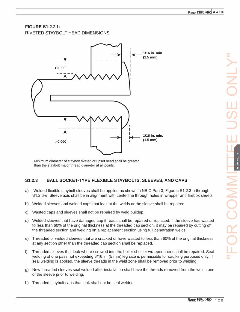
108
2015
SECTION 6
SU
PPL. 1
NB-23
FIGURE S1.2.2-b RIVETED STAYBOLT HEAD DIMENSIONS
1/16 in. min.(1.5 mm)
1/16 in. min.(1.5 mm)
>0.000
>0.000
Minimum diameter of staybolt riveted or upset head shall be greater than the staybolt major thread diameter at all points.
S1.2.3 BALL SOCKET-TYPE FLEXIBLE STAYBOLTS, SLEEVES, AND CAPS
a) Welded flexible staybolt sleeves shall be applied as shown in NBIC Part 3, Figures S1.2.3-a through S1.2.3-e. Sleeve axis shall be in alignment with centerline through holes in wrapper and firebox sheets.
b) Welded sleeves and welded caps that leak at the welds or the sleeve shall be repaired.
c) Wasted caps and sleeves shall not be repaired by weld buildup.
d) Welded sleeves that have damaged cap threads shall be repaired or replaced. If the sleeve has wasted to less than 60% of the original thickness at the threaded cap section, it may be repaired by cutting off the threaded section and welding on a replacement section using full penetration welds.
e) Threaded or welded sleeves that are cracked or have wasted to less than 60% of the original thickness at any section other than the threaded cap section shall be replaced.
f) Threaded sleeves that leak where screwed into the boiler shell or wrapper sheet shall be repaired. Seal welding of one pass not exceeding 3/16 in. (5 mm) leg size is permissible for caulking purposes only. If seal welding is applied, the sleeve threads in the weld zone shall be removed prior to welding.
g) New threaded sleeves seal welded after installation shall have the threads removed from the weld zone of the sleeve prior to welding.
h) Threaded staybolt caps that leak shall not be seal welded.
"FO
RC
OM
MIT
TEE
CO
MM
ITTE
EC
OM
MIT
TEE
SU
PPL. 1
CO
MM
ITTE
ES
UPPL. 1
US
EO
NLY
"
Page 138 of 400
Page 138 of 400

109
NATIONAL BOARD INSPECTION CODE2015
SECTION 6
SU
PPL. 1
i) Substitution of one type of flexible staybolt sleeve by another type shall be considered a repair.
j) Where necessary for boiler expansion, ball socket-type flexible staybolts shall be positioned in such a manner as to not interfere with boiler expansion. Where individual bolts are replaced, care should be taken to ensure that the stress load of the new bolt is compatible to the loading on adjacent bolts.
Note: Some locomotive boiler designs positioned the bolts by backing the bolt head away from the sleeve socket bottom a certain amount.
FIGURE S1.2.3-a
1/4” to 5/16” Weld
1/4” to 5/16” Weld
1/4” to 5/16”Weld
Electric Weld
Electric Weld
1-3/8”
1/8”
1/8”
1/8”
1/8”
1/8”
1/8”
1/8”
1/8”
1-3/8” 1-3/8”
1/8”
1/8”
5˚ 10˚1-3/8”
1/8”
1-3/8”
1/8”
1/8”15˚ 20˚
1-3/8”
25˚ 1/8”
1-3/8”
30˚
5˚
5˚ 10˚ 15˚
10˚ 15˚ 20˚ 25˚ 30˚
Application of welded type staybolt sleeves
Old wrapper sheets
New wrapper sheets
FIGURE S1.2.3-bBALL SOCKET-TYPE FLEXIBLE STAYBOLTS
Welded cover cap
ball socket staybolt
ball socket staybolt
welded sleeve
welded sleeve
ball socket staybolt consisting of a spherical nut on a threadedrigid staybolt
threaded cover cap
threaded cover cap
Welded cover cap type
Welded Sleeve with Threaded Cover Cap Type
Threaded Sleeve with Threaded Cover Cap Type
ball socket staybolt
"FO
RC
OM
MIT
TEE
US
EO
NLY
"
Page 139 of 400
Page 139 of 400
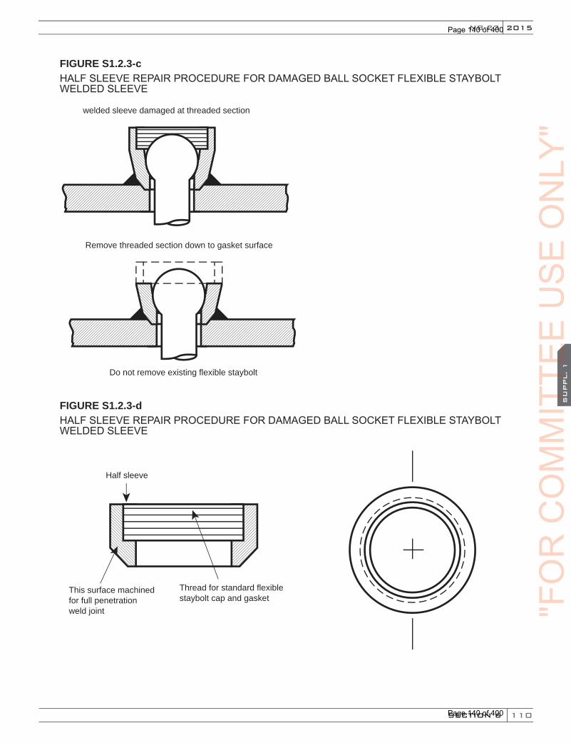
110
2015
SECTION 6
SU
PPL. 1
NB-23
FIGURE S1.2.3-cHALF SLEEVE REPAIR PROCEDURE FOR DAMAGED BALL SOCKET FLEXIBLE STAYBOLT WELDED SLEEVE
Remove threaded section down to gasket surface
welded sleeve damaged at threaded section
Do not remove existing flexible staybolt
FIGURE S1.2.3-dHALF SLEEVE REPAIR PROCEDURE FOR DAMAGED BALL SOCKET FLEXIBLE STAYBOLT WELDED SLEEVE
Half sleeve
Thread for standard flexible staybolt cap and gasket
This surface machined for full penetration weld joint "F
OR
CO
MM
ITTE
EC
OM
MIT
TEE
CO
MM
ITTE
ES
UPPL. 1
CO
MM
ITTE
ES
UPPL. 1
US
EO
NLY
"
Page 140 of 400
Page 140 of 400
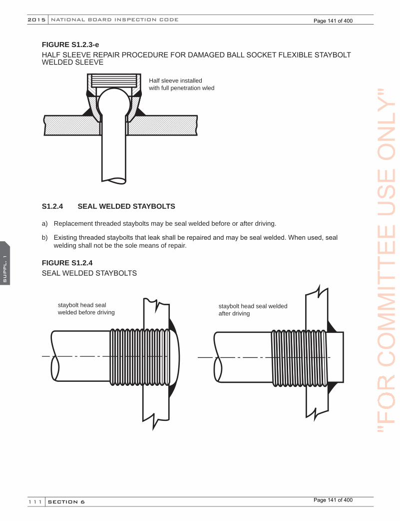
111
NATIONAL BOARD INSPECTION CODE2015
SECTION 6
SU
PPL. 1
FIGURE S1.2.3-eHALF SLEEVE REPAIR PROCEDURE FOR DAMAGED BALL SOCKET FLEXIBLE STAYBOLT WELDED SLEEVE
Half sleeve installedwith full penetration wled
S1.2.4 SEAL WELDED STAYBOLTS
a) Replacement threaded staybolts may be seal welded before or after driving.
b) Existing threaded staybolts that leak shall be repaired and may be seal welded. When used, seal welding shall not be the sole means of repair.
FIGURE S1.2.4SEAL WELDED STAYBOLTS
staybolt head seal welded before driving
staybolt head seal welded after driving
"FO
RC
OM
MIT
TEE
US
EO
NLY
"
Page 141 of 400
Page 141 of 400
112
2015
SECTION 6
SU
PPL. 1
NB-23
S1.2.5 WELDED INSTALLATION OF STAYBOLTS
a) The installation of unthreaded staybolts using full penetration welds is permissible.
b) All staybolts shorter than 8 in. (200 mm) in length shall have telltale holes. Telltale hole diameter shall be 3/16 in. (5 mm) to 7/32 in. (5.5 mm) in diameter and at least 1-1/4 in. (32 mm) deep in the outer end. On reduced body staybolts, the telltale hole shall extend beyond the fillet and into the reduced section of the staybolt. Staybolts should have through telltale holes, which are preferred. Ball socket-type flexible staybolts may have telltale holes that extend from the welded end of the bolt into the bolt head for a distance of one-third the spherical bolt head diameter.
c) Where necessary for boiler expansion, ball socket-type flexible staybolts shall be positioned in such a manner as to not interfere with boiler expansion. Where individual bolts are replaced, care should be taken to ensure that the stress load of the new bolt is compatible to the loading of adjacent bolts.
Note: Some locomotive boiler designs positioned the bolts by backing the bolt head away from the sleeve socket bottom a certain amount.
d) Installation of different diameter staybolts shall be considered a repair.
S1.2.6 DIAGONAL BRACES, GUSSET BRACES, AND THROAT SHEET/TUBESHEET BRACES
a) Loose or damaged braces shall be repaired or replaced.
b) Only steel braces may be repaired by welding. All such welds shall be full penetration. Wrought iron braces shall not be repaired by welding. When repairs or alterations are completed, the tightness and condition of the braces and their staybolts, rivets, clevises, eyes, and pins shall be verified.
c) For pins that are fitted with nuts, the pin length shall be sized so that all threads of the nut are engaged upon completion of installation.
d) Replacement of diagonal stays having loop-type ends shall be considered a repair.
"FO
RC
OM
MIT
TEE
CO
MM
ITTE
EC
OM
MIT
TEE
SU
PPL. 1
CO
MM
ITTE
ES
UPPL. 1
US
EO
NLY
"
Page 142 of 400
Page 142 of 400

113
NATIONAL BOARD INSPECTION CODE2015
SECTION 6
SU
PPL. 1
FIGURE S1.2.6-aDIAGONAL BRACES, GUSSET BRACES, AND THROAT SHEET/TUBESHEET BRACES
throat sheet/tubesheet brace
gusset brace
solid-type brace
pin-type diagonal bracediagonal brace
FIGURE S1.2.6-bDIAGONAL BRACE ENDS
Loop-Type End One-Piece End
Diagonal Brace Ends
"FO
RC
OM
MIT
TEE
US
EO
NLY
"
Page 143 of 400
Page 143 of 400
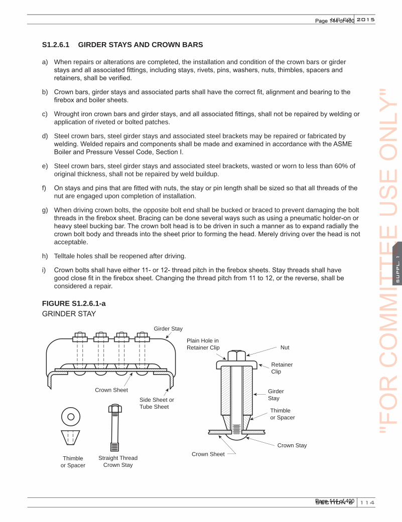
114
2015
SECTION 6
SU
PPL. 1
NB-23
S1.2.6.1 GIRDER STAYS AND CROWN BARS
a) When repairs or alterations are completed, the installation and condition of the crown bars or girder stays and all associated fittings, including stays, rivets, pins, washers, nuts, thimbles, spacers and retainers, shall be verified.
b) Crown bars, girder stays and associated parts shall have the correct fit, alignment and bearing to the firebox and boiler sheets.
c) Wrought iron crown bars and girder stays, and all associated fittings, shall not be repaired by welding or application of riveted or bolted patches.
d) Steel crown bars, steel girder stays and associated steel brackets may be repaired or fabricated by welding. Welded repairs and components shall be made and examined in accordance with the ASME Boiler and Pressure Vessel Code, Section I.
e) Steel crown bars, steel girder stays and associated steel brackets, wasted or worn to less than 60% of original thickness, shall not be repaired by weld buildup.
f) On stays and pins that are fitted with nuts, the stay or pin length shall be sized so that all threads of the nut are engaged upon completion of installation.
g) When driving crown bolts, the opposite bolt end shall be bucked or braced to prevent damaging the bolt threads in the firebox sheet. Bracing can be done several ways such as using a pneumatic holder-on or heavy steel bucking bar. The crown bolt head is to be driven in such a manner as to expand radially the crown bolt body and threads into the sheet prior to forming the head. Merely driving over the head is not acceptable.
h) Telltale holes shall be reopened after driving.
i) Crown bolts shall have either 11- or 12- thread pitch in the firebox sheets. Stay threads shall have good close fit in the firebox sheet. Changing the thread pitch from 11 to 12, or the reverse, shall be considered a repair.
FIGURE S1.2.6.1-aGRINDER STAY
Thimbleor Spacer
Straight ThreadCrown Stay
Crown Sheet
Nut
RetainerClip
GirderStay
Thimbleor Spacer
Plain Hole in Retainer Clip
Crown Stay
Crown Sheet
Side Sheet orTube Sheet
Girder Stay
"FO
RC
OM
MIT
TEE
CO
MM
ITTE
EC
OM
MIT
TEE
SU
PPL. 1
CO
MM
ITTE
ES
UPPL. 1
US
EO
NLY
"
Page 144 of 400
Page 144 of 400
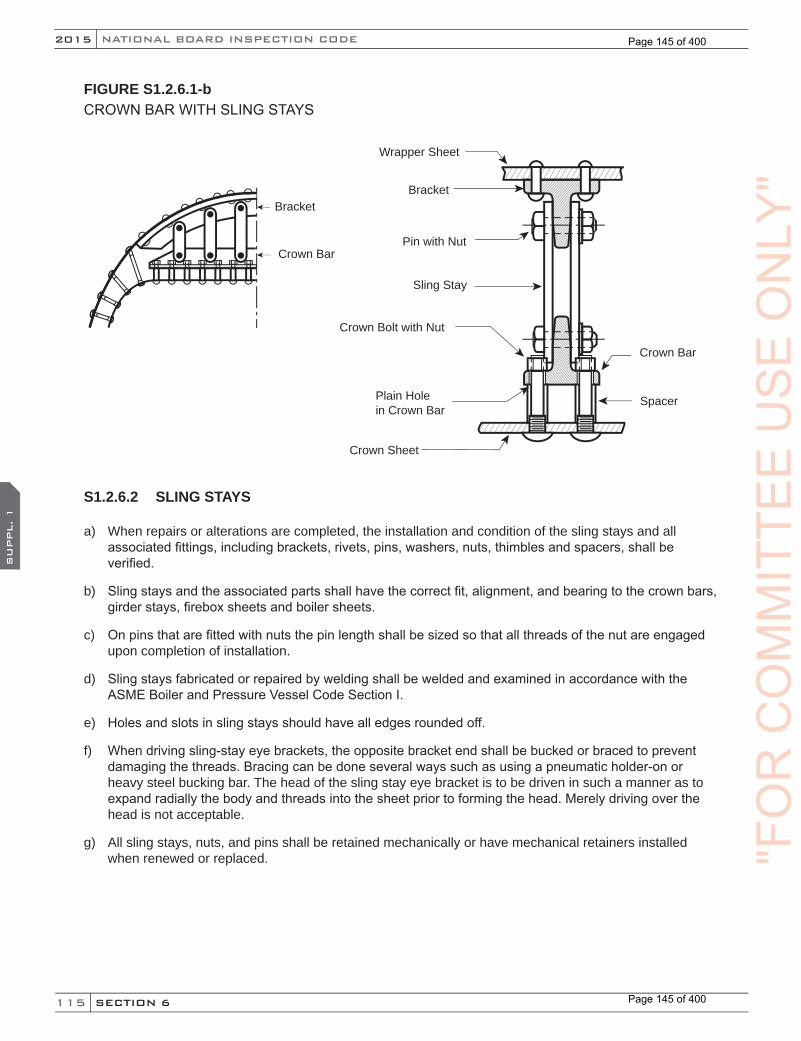
115
NATIONAL BOARD INSPECTION CODE2015
SECTION 6
SU
PPL. 1
FIGURE S1.2.6.1-bCROWN BAR WITH SLING STAYS
Bracket
Crown Bar
Wrapper Sheet
Bracket
Pin with Nut
Sling Stay
Crown Bolt with Nut
Plain Hole in Crown Bar
Crown Sheet
Spacer
Crown Bar
S1.2.6.2 SLING STAYS
a) When repairs or alterations are completed, the installation and condition of the sling stays and all associated fittings, including brackets, rivets, pins, washers, nuts, thimbles and spacers, shall be verified.
b) Sling stays and the associated parts shall have the correct fit, alignment, and bearing to the crown bars, girder stays, firebox sheets and boiler sheets.
c) On pins that are fitted with nuts the pin length shall be sized so that all threads of the nut are engaged upon completion of installation.
d) Sling stays fabricated or repaired by welding shall be welded and examined in accordance with the ASME Boiler and Pressure Vessel Code Section I.
e) Holes and slots in sling stays should have all edges rounded off.
f) When driving sling-stay eye brackets, the opposite bracket end shall be bucked or braced to prevent damaging the threads. Bracing can be done several ways such as using a pneumatic holder-on or heavy steel bucking bar. The head of the sling stay eye bracket is to be driven in such a manner as to expand radially the body and threads into the sheet prior to forming the head. Merely driving over the head is not acceptable.
g) All sling stays, nuts, and pins shall be retained mechanically or have mechanical retainers installed when renewed or replaced. "F
OR
CO
MM
ITTE
EU
SE
ON
LY"
Page 145 of 400
Page 145 of 400
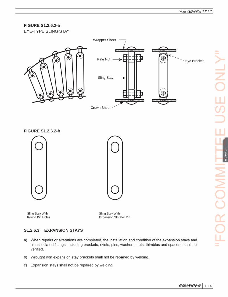
116
2015
SECTION 6
SU
PPL. 1
NB-23
FIGURE S1.2.6.2-aEYE-TYPE SLING STAY
Wrapper Sheet
Pine Nut
Sling Stay
Crown Sheet
Eye Bracket
FIGURE S1.2.6.2-b
Sling Stay With Round Pin Holes
Sling Stay With Expansion Slot For Pin
S1.2.6.3 EXPANSION STAYS
a) When repairs or alterations are completed, the installation and condition of the expansion stays and all associated fittings, including brackets, rivets, pins, washers, nuts, thimbles and spacers, shall be verified.
b) Wrought iron expansion stay brackets shall not be repaired by welding.
c) Expansion stays shall not be repaired by welding.
"FO
RC
OM
MIT
TEE
CO
MM
ITTE
EC
OM
MIT
TEE
SU
PPL. 1
CO
MM
ITTE
ES
UPPL. 1
US
EO
NLY
"
Page 146 of 400
Page 146 of 400

117
NATIONAL BOARD INSPECTION CODE2015
SECTION 6
SU
PPL. 1
d) Worn pin holes and expansion slots of steel expansion stay brackets may be repaired by welding.
e) On stays and pins that are fitted with nuts, the stay or pin Iength shall be sized so that all threads of the nut are engaged upon completion of installation.
f) Stay length shall be sized so the length of the stay projecting through the sheet is not less than 1/8 in. (3.2 mm) and is sufficient to produce a full head after driving.
g) Stays shall have either 11 or 12 thread pitch. Stay threads shall have good close fit in the sheet. Changing the thread pitch from 11 to 12 or the reverse, shall be considered a repair.
h) Installation of expansion stays that have a different diameter in the firebox sheet shall be considered a repair.
i) Installation of expansion stays that have a different diameter in the bracket shall be considered a repair, provided the changes are within the stress limits of the original code of construction.
j) When driving expansion stay heads, the opposite end shall be bucked or braced to prevent damaging the threads. Bracing can be done several ways, such as using a pneumatic holder-on or heavy steel bucking bar. The stay head is to be driven in such a manner as to expand radially the stay body and threads into the sheet prior to forming the head. Merely driving over the head is not acceptable.
k) Telltale holes shall be reopened after driving.
FIGURE S1.2.6.3-aEXPANSION STAY
Wrapper Sheet
Pin & Retainer
Plain Hole in Bracket
ExpansionStay
Crown Sheet
Bracket
Nut
"FO
RC
OM
MIT
TEE
US
EO
NLY
"
Page 147 of 400
Page 147 of 400

118
2015
SECTION 6
SU
PPL. 1
NB-23
FIGURE S1.2.6.3-bBALDWIN-TYPE EXPANSION STAY
Wrapper Sheet
Bracket
Plain Hole in Bracket
Expansion Stay
Firebox Crown Sheet
S1.2.7 THREADED STUDS
Studs threaded into the boiler or firebox sheets shall not be seal welded.
S1.2.8 PATCH BOLTS
a) Patch bolts may be replaced in kind.
b) Seal welding of bolts is permitted.
c) Patch bolts shall have either 11 or 12 thread pitch. Patch bolt threads shall be fit to support the structure to which the bolt is applied. Changing the patch bolt thread from 11 to 12, or the reverse, shall be considered a repair.
d) A patch bolt applied in place of a rivet shall be considered an alteration.
FIGURE S1.2.8PATCH BOLTS
Typical patch bolt Typical patch bolt application"F
OR
CO
MM
ITTE
EC
OM
MIT
TEE
CO
MM
ITTE
ES
UPPL. 1
CO
MM
ITTE
ES
UPPL. 1
US
EO
NLY
"
Page 148 of 400
Page 148 of 400

119
NATIONAL BOARD INSPECTION CODE2015
SECTION 6
SU
PPL. 1
S1.2.9 FLUES, ARCH TUBES, CIRCULATORS, THERMIC SYPHONS
TABLE S1.2.9.1MAXIMUM ALLOWABLE WORKING PRESSURES FOR STEEL TUBES OR FLUES FOR FIRETUBE BOILERS FOR DIFFERENT DIAMETERS AND GAGES OF TUBES CONFORMING TO THE REQUIREMENTS OF SPEC. SA-178, SA-192, SA-209, OR SA-210*
Outsidediameter oftube, inches
D
Minimum gage, Birmingham Wire Gage (BWG), inches13
t = 0.09512
t = 0.10911
t = 0.12010
t = 0.1349
t = 0.1488
t = 0.1657
t = 0.1806
t = 0.2035
t = 0.2204
t = 0.238
1 470 690 — — — — — — — —1-1/2 320 460 570 720 860 — — — — —1-3/4 270 400 490 620 740 890 — — — —
2 240 350 430 540 650 780 900 — — —2-1/4 210 310 380 480 580 690 800 960 — —2-1/2 190 280 350 430 520 620 720 860 970 1,080
3 160 230 290 360 430 520 600 720 810 9003-1/4 — 210 270 330 400 480 550 660 740 8303-1/2 — 200 250 310 370 450 510 620 690 770
4 — 180 220 270 330 390 450 540 610 6804-1/2 — 160 190 240 290 350 400 480 540 600
5 — — 180 220 260 310 360 430 490 5405-3/8 — — 160 200 240 290 340 400 450 5005-1/2 — — — 200 240 290 330 390 440 490
6 — — — 180 220 260 300 360 410 450P = {(t–0.65)/D} x 15550 where P = maximum allowable working pressure, pounds per square inch,
t = minimum wall thickness, inches, D = outside diameter of tubes, inches.
For pressures below those given in the table, the gage thickness shall be not less than the minimum given in the table. * Calculated values of pressure have been rounded to the next higher unit of 10 psi.
"FO
RC
OM
MIT
TEE
US
EO
NLY
"
Page 149 of 400
Page 149 of 400
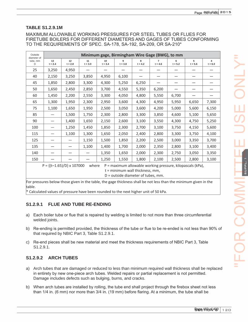
120
2015
SECTION 6
SU
PPL. 1
NB-23
TABLE S1.2.9.1MMAXIMUM ALLOWABLE WORKING PRESSURES FOR STEEL TUBES OR FLUES FOR FIRETUBE BOILERS FOR DIFFERENT DIAMETERS AND GAGES OF TUBES CONFORMING TO THE REQUIREMENTS OF SPEC. SA-178, SA-192, SA-209, OR SA-210*
Outsidediameter oftube, mm
D
Minimum gage, Birmingham Wire Gage (BWG), to mm13
t = 2.412
t = 2.811
t = 3.010
t = 3.49
t = 3.88
t = 4.27
t = 4.66
t = 5.25
t = 5.64
t = 6.0
25 3,250 4,950 — — — — — — — —40 2,150 3,250 3,850 4,950 6,100 — — — — —45 1,850 2,800 3,300 4,300 5,250 6,250 — — — —50 1,650 2,450 2,850 3,700 4,550 5,350 6,200 — — —60 1,450 2,200 2,550 3,300 4,050 4,800 5,550 6,700 — —65 1,300 1,950 2,300 2,950 3,600 4,300 4,950 5,950 6,650 7,30075 1,100 1,650 1,950 2,500 3,050 3,600 4,200 5,000 5,600 6,15085 — 1,500 1,750 2,300 2,800 3,300 3,850 4,600 5,100 5,65090 — 1,400 1,650 2,150 2,600 3,100 3,550 4,300 4,750 5,250
100 — 1,250 1,450 1,850 2,300 2,700 3,100 3,750 4,150 5,600115 — 1,100 1,300 1,650 2,050 2,400 2,800 3,300 3,750 4,100125 — — 1,150 1,500 1,850 2,200 2,500 3,000 3,350 3,700135 — — 1,100 1,400 1,700 2,000 2,350 2,800 3,100 3,400140 — — — 1,350 1,650 2,000 2,300 2,750 3,050 3,350150 — — — 1,250 1,550 1,800 2,100 2,500 2,800 3,100
P = {(t–1.65)/D} x 107000 where P = maximum allowable working pressure, kilopascals (kPa), t = minimum wall thickness, mm,
D = outside diameter of tubes, mm.For pressures below those given in the table, the gage thickness shall be not less than the minimum given in the table. * Calculated values of pressure have been rounded to the next higher unit of 50 kPa.
S1.2.9.1 FLUE AND TUBE RE-ENDING
a) Each boiler tube or flue that is repaired by welding is limited to not more than three circumferential welded joints.
b) Re-ending is permitted provided, the thickness of the tube or flue to be re-ended is not less than 90% of that required by NBIC Part 3, Table S1.2.9.1.
c) Re-end pieces shall be new material and meet the thickness requirements of NBIC Part 3, Table S1.2.9.1.
S1.2.9.2 ARCH TUBES
a) Arch tubes that are damaged or reduced to less than minimum required wall thickness shall be replaced in entirety by new one-piece arch tubes. Welded repairs or partial replacement is not permitted. Damage includes defects such as bulging, burns, and cracks.
b) When arch tubes are installed by rolling, the tube end shall project through the firebox sheet not less than 1/4 in. (6 mm) nor more than 3/4 in. (19 mm) before flaring. At a minimum, the tube shall be
"FO
RC
OM
MIT
TEE
CO
MM
ITTE
EC
OM
MIT
TEE
SU
PPL. 1
CO
MM
ITTE
ES
UPPL. 1
US
EO
NLY
"
Page 150 of 400
Page 150 of 400
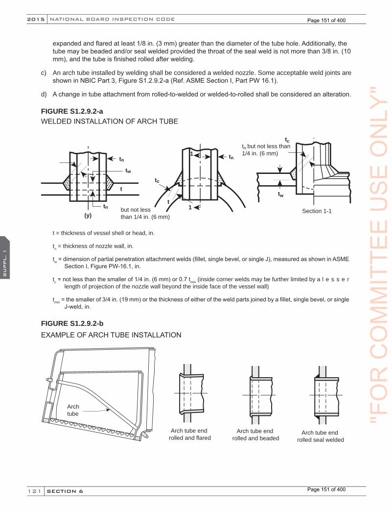
121
NATIONAL BOARD INSPECTION CODE2015
SECTION 6
SU
PPL. 1
expanded and flared at least 1/8 in. (3 mm) greater than the diameter of the tube hole. Additionally, the tube may be beaded and/or seal welded provided the throat of the seal weld is not more than 3/8 in. (10 mm), and the tube is finished rolled after welding.
c) An arch tube installed by welding shall be considered a welded nozzle. Some acceptable weld joints are shown in NBIC Part 3, Figure S1.2.9.2-a (Ref. ASME Section I, Part PW 16.1).
d) A change in tube attachment from rolled-to-welded or welded-to-rolled shall be considered an alteration.
FIGURE S1.2.9.2-aWELDED INSTALLATION OF ARCH TUBE
(y)tn
tn
tw
t
tn but not less than 1/4 in. (6 mm)
Section 1-1
tc
tw
tn
tc
t1but not less
than 1/4 in. (6 mm)
1
t = thickness of vessel shell or head, in.
tn = thickness of nozzle wall, in.
tw = dimension of partial penetration attachment welds (fillet, single bevel, or single J), measured as shown in ASME Section I, Figure PW-16.1, in.
tc = not less than the smaller of 1/4 in. (6 mm) or 0.7 tmin (inside corner welds may be further limited by a l e s s e r length of projection of the nozzle wall beyond the inside face of the vessel wall)
tmin = the smaller of 3/4 in. (19 mm) or the thickness of either of the weld parts joined by a fillet, single bevel, or single J-weld, in.
FIGURE S1.2.9.2-bEXAMPLE OF ARCH TUBE INSTALLATION
Archtube
Arch tube end rolled and flared
Arch tube end rolled and beaded
Arch tube end rolled seal welded
"FO
RC
OM
MIT
TEE
US
EO
NLY
"
Page 151 of 400
Page 151 of 400

122
2015
SECTION 6
SU
PPL. 1
NB-23
S1.2.9.3 TUBE WALL THICKNESS FOR ARCH TUBES
The minimum wall thickness of replacement arch tubes shall be as shown in Table S1.2.9.3.
TABLE S1.2.9.3
Size Wall ThicknessUp to 3 in. (75 mm) OD 8 Birmingham wire gage (BWG)
More than 3 in. (75 mm) OD to 4 in. (100 mm) OD 7 Birmingham wire gage (BWG)
S1.2.9.4 THERMIC SYPHONS
a) For repairs to syphon knuckles see Repair of Firebox and Tubesheet Knuckles, and NBIC Part 3, Figures S1.2.11.5-a and S1.2.11.5-b.
b) All weld repairs to the unstayed sections of the syphon neck and body shall be radiographically examined.
FIGURE S1.2.9.4-aLOCOMOTIVE FIREBOX THERMIC SYPHON INSTALLATION
thermic syphonneck
staybolt body
"FO
RC
OM
MIT
TEE
CO
MM
ITTE
EC
OM
MIT
TEE
SU
PPL. 1
CO
MM
ITTE
ES
UPPL. 1
US
EO
NLY
"
Page 152 of 400
Page 152 of 400
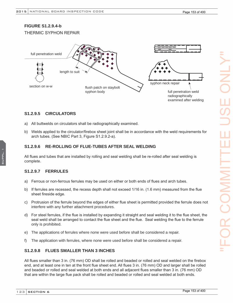
123
NATIONAL BOARD INSPECTION CODE2015
SECTION 6
SU
PPL. 1
FIGURE S1.2.9.4-bTHERMIC SYPHON REPAIR
full penetration weldradiographicallyexamined after welding
syphon neck repair
full penetration weld
flush patch on staybolt syphon body
length to suit
section on w-w
S1.2.9.5 CIRCULATORS
a) All buttwelds on circulators shall be radiographically examined.
b) Welds applied to the circulator/firebox sheet joint shall be in accordance with the weld requirements for arch tubes. (See NBIC Part 3, Figure S1.2.9.2-a).
S1.2.9.6 RE-ROLLING OF FLUE-TUBES AFTER SEAL WELDING
All flues and tubes that are installed by rolling and seal welding shall be re-rolled after seal welding is complete.
S1.2.9.7 FERRULES
a) Ferrous or non-ferrous ferrules may be used on either or both ends of flues and arch tubes.
b) If ferrules are recessed, the recess depth shall not exceed 1/16 in. (1.6 mm) measured from the flue sheet fireside edge.
c) Protrusion of the ferrule beyond the edges of either flue sheet is permitted provided the ferrule does not interfere with any further attachment procedures.
d) For steel ferrules, if the flue is installed by expanding it straight and seal welding it to the flue sheet, the seal weld shall be arranged to contact the flue sheet and the flue. Seal welding the flue to the ferrule only is prohibited.
e) The applications of ferrules where none were used before shall be considered a repair.
f) The application with ferrules, where none were used before shall be considered a repair.
S1.2.9.8 FLUES SMALLER THAN 3 INCHES
All flues smaller than 3 in. (76 mm) OD shall be rolled and beaded or rolled and seal welded on the firebox end, and at least one in ten at the front flue sheet end. All flues 3 in. (76 mm) OD and larger shall be rolled and beaded or rolled and seal welded at both ends and all adjacent flues smaller than 3 in. (76 mm) OD that are within the large flue pack shall be rolled and beaded or rolled and seal welded at both ends.
"FO
RC
OM
MIT
TEE
US
EO
NLY
"
Page 153 of 400
Page 153 of 400
124
2015
SECTION 6
SU
PPL. 1
NB-23
At least one in ten of the remaining flues smaller than 3 in. (76 mm) OD shall be beaded or seal welded on the front flue sheet, in addition to rolling. Where less than all flues are seal welded or beaded on the front flue sheet, those seal welded or beaded shall be distributed as evenly as practicable throughout the flue pack. This shall be considered a repair.
S1.2.10 REPAIRS AND ALTERATIONS TO BOILER BARREL UNSTAYED AREAS
a) Except as provided in NBIC Part 3, 3.4.4.8, a repair of a defect in a welded joint or base material shall not be made until the defect is removed. A suitable nondestructive examination (NDE) method such as magnetic particle (MT) or liquid penetrant (PT) may be necessary to ensure complete removal of the defect. If the defect penetrates the full thickness of the material, the repair shall be made with a full penetration weld such as a double buttweld or a single buttweld with or without backing. Where circumstances indicate that the defect is likely to recur, consideration should be given to removing the defective area and installing a flush patch or taking other corrective measures acceptable to the Inspector, and when required by the Jurisdiction.
b) Weld buildup shall not be used if the affected section of plate has wasted below 60% of the minimum required thickness.
c) If the cracked section of plate is retained and is to be repaired by installation of a riveted patch, the crack may be stopped by drilling stop holes at each end or removed by a method such as grinding, cutting, or machining. Results of stop drilling or crack removal shall be verified by NDE.
d) Welded repairs at or near riveted seams requiring preheating or postweld heat treatment shall be carefully made in order to prevent loosening in the riveted seams, especially when localized heating is used. Where necessary to control expansion or to gain access for welding, rivets at the defective section and to each side of it may be removed. Reuse of rivets and staybolts is prohibited.
e) All welded repairs to boiler barrel unstayed areas shall be radiographically examined in accordance with ASME Code, Section I when the size of the repaired area is greater than the maximum size of an unreinforced opening as calculated in accordance with the latest edition of ASME Code, Section I.
f) Riveted patches may be any shape or size provided the lowest patch efficiency is equal to or greater than the lowest equivalent seam efficiency of the boiler course to which it is applied. Ref: ASME Code, Section I.
g) The factor of safety of all riveted patches shall not be less than four for locomotives operating under Federal Railroad Administration regulations.
S1.2.11 REPAIRS AND ALTERATIONS TO BOILER BARREL STAYED AREA
S1.2.11.1 FIREBOX SHEET REPAIR
a) Cracks in all stayed firebox sheets may be repaired by welding or the installation of a flush patch.
b) If the crack extends into a staybolt or rivet hole, the staybolt or rivet shall be removed prior to making the repair.
c) Fire cracks or thermal fatigue cracks in riveted seams located in the firebox that run from the edge of the plate into the rivet holes may be left in place provided they do not leak and there is no indication that the seam or rivets are loose. (See NBIC Part 3, Figure S1.2.11.1).
"FO
RC
OM
MIT
TEE
CO
MM
ITTE
EC
OM
MIT
TEE
SU
PPL. 1
CO
MM
ITTE
ES
UPPL. 1
US
EO
NLY
"
Page 154 of 400
Page 154 of 400
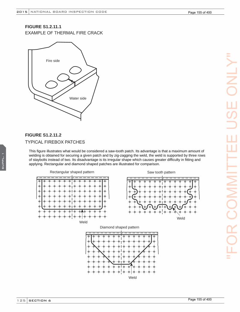
125
NATIONAL BOARD INSPECTION CODE2015
SECTION 6
SU
PPL. 1
FIGURE S1.2.11.1EXAMPLE OF THERMAL FIRE CRACK
Fire side
Water side
FIGURE S1.2.11.2TYPICAL FIREBOX PATCHES
Rectangular shaped pattern
Weld
Saw tooth pattern
Weld
Diamond shaped pattern
Weld
This figure illustrates what would be considered a saw-tooth patch. Its advantage is that a maximum amount of welding is obtained for securing a given patch and by zig-zagging the weld, the weld is supported by three rows of staybolts instead of two. Its disadvantage is its irregular shape which causes greater difficulty in fitting and applying. Rectangular and diamond shaped patches are illustrated for comparison.
"FO
RC
OM
MIT
TEE
US
EO
NLY
"
Page 155 of 400
Page 155 of 400
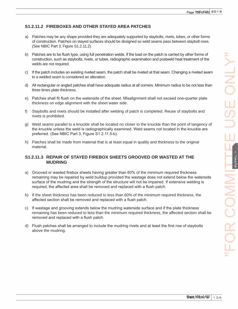
126
2015
SECTION 6
SU
PPL. 1
NB-23
S1.2.11.2 FIREBOXES AND OTHER STAYED AREA PATCHES
a) Patches may be any shape provided they are adequately supported by staybolts, rivets, tubes, or other forms of construction. Patches on stayed surfaces should be designed so weld seams pass between staybolt rows. (See NBIC Part 3, Figure S1.2.11.2).
b) Patches are to be flush type, using full penetration welds. If the load on the patch is carried by other forms of construction, such as staybolts, rivets, or tubes, radiographic examination and postweld heat treatment of the welds are not required.
c) If the patch includes an existing riveted seam, the patch shall be riveted at that seam. Changing a riveted seam to a welded seam is considered an alteration.
d) All rectangular or angled patches shall have adequate radius at all corners. Minimum radius to be not less than three times plate thickness.
e) Patches shall fit flush on the waterside of the sheet. Misalignment shall not exceed one-quarter plate thickness on edge alignment with the sheet water side.
f) Staybolts and rivets should be installed after welding of patch is completed. Reuse of staybolts and rivets is prohibited.
g) Weld seams parallel to a knuckle shall be located no closer to the knuckle than the point of tangency of the knuckle unless the weld is radiographically examined. Weld seams not located in the knuckle are preferred. (See NBIC Part 3, Figure S1.2.11.5-b).
h) Patches shall be made from material that is at least equal in quality and thickness to the original material.
S1.2.11.3 REPAIR OF STAYED FIREBOX SHEETS GROOVED OR WASTED AT THE MUDRING
a) Grooved or wasted firebox sheets having greater than 60% of the minimum required thickness remaining may be repaired by weld buildup provided the wastage does not extend below the waterside surface of the mudring and the strength of the structure will not be impaired. If extensive welding is required, the affected area shall be removed and replaced with a flush patch.
b) If the sheet thickness has been reduced to less than 60% of the minimum required thickness, the affected section shall be removed and replaced with a flush patch.
c) If wastage and grooving extends below the mudring waterside surface and if the plate thickness remaining has been reduced to less than the minimum required thickness, the affected section shall be removed and replaced with a flush patch.
d) Flush patches shall be arranged to include the mudring rivets and at least the first row of staybolts above the mudring.
"FO
RC
OM
MIT
TEE
CO
MM
ITTE
EC
OM
MIT
TEE
SU
PPL. 1
CO
MM
ITTE
ES
UPPL. 1
US
EO
NLY
"
Page 156 of 400
Page 156 of 400
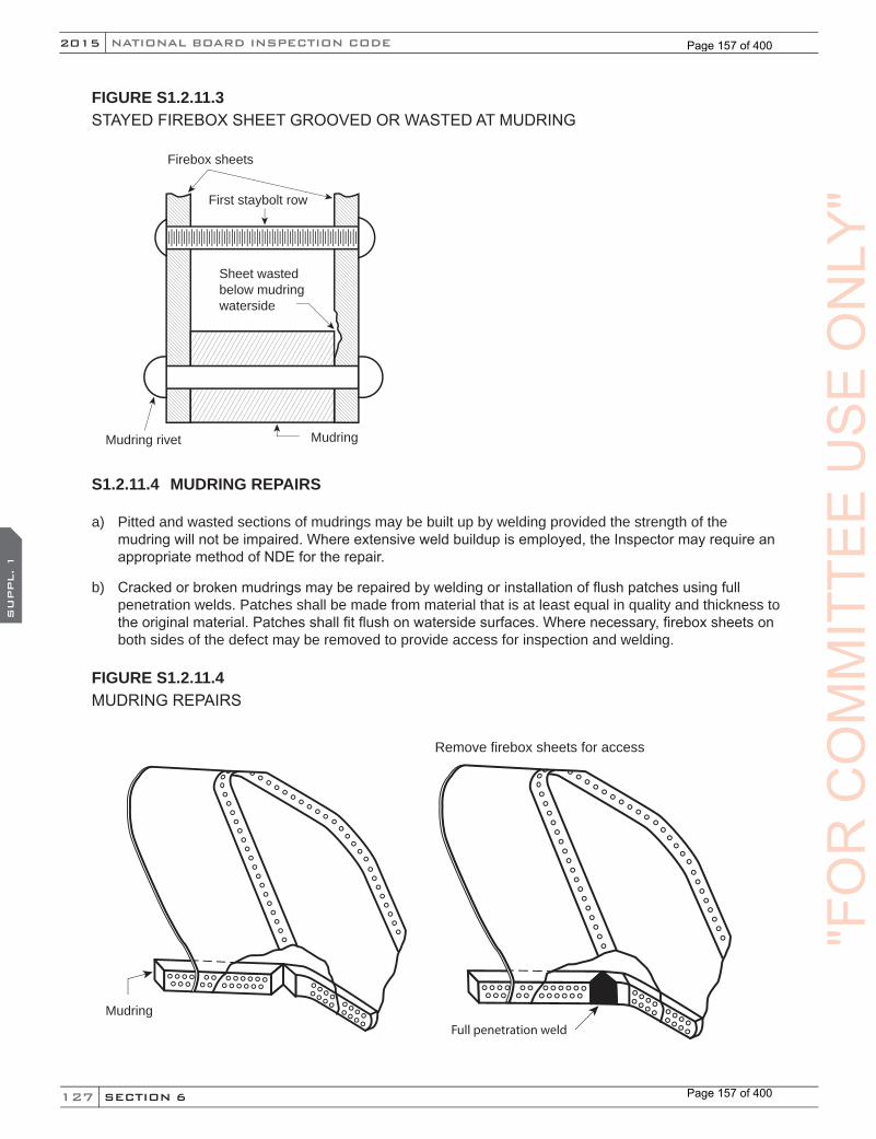
127
NATIONAL BOARD INSPECTION CODE2015
SECTION 6
SU
PPL. 1
FIGURE S1.2.11.3STAYED FIREBOX SHEET GROOVED OR WASTED AT MUDRING
Mudring rivet Mudring
Sheet wasted below mudring waterside
First staybolt row
Firebox sheets
S1.2.11.4 MUDRING REPAIRS
a) Pitted and wasted sections of mudrings may be built up by welding provided the strength of the mudring will not be impaired. Where extensive weld buildup is employed, the Inspector may require an appropriate method of NDE for the repair.
b) Cracked or broken mudrings may be repaired by welding or installation of flush patches using full penetration welds. Patches shall be made from material that is at least equal in quality and thickness to the original material. Patches shall fit flush on waterside surfaces. Where necessary, firebox sheets on both sides of the defect may be removed to provide access for inspection and welding.
FIGURE S1.2.11.4MUDRING REPAIRS
Mudring
Remove firebox sheets for access
Full penetration weld
"FO
RC
OM
MIT
TEE
US
EO
NLY
"
Page 157 of 400
Page 157 of 400
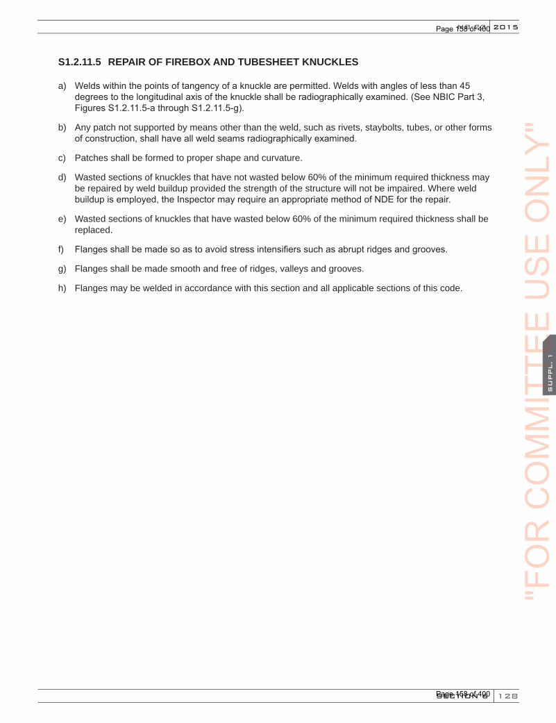
128
2015
SECTION 6
SU
PPL. 1
NB-23
S1.2.11.5 REPAIR OF FIREBOX AND TUBESHEET KNUCKLES
a) Welds within the points of tangency of a knuckle are permitted. Welds with angles of less than 45 degrees to the longitudinal axis of the knuckle shall be radiographically examined. (See NBIC Part 3, Figures S1.2.11.5-a through S1.2.11.5-g).
b) Any patch not supported by means other than the weld, such as rivets, staybolts, tubes, or other forms of construction, shall have all weld seams radiographically examined.
c) Patches shall be formed to proper shape and curvature.
d) Wasted sections of knuckles that have not wasted below 60% of the minimum required thickness may be repaired by weld buildup provided the strength of the structure will not be impaired. Where weld buildup is employed, the Inspector may require an appropriate method of NDE for the repair.
e) Wasted sections of knuckles that have wasted below 60% of the minimum required thickness shall be replaced.
f) Flanges shall be made so as to avoid stress intensifiers such as abrupt ridges and grooves.
g) Flanges shall be made smooth and free of ridges, valleys and grooves.
h) Flanges may be welded in accordance with this section and all applicable sections of this code.
"FO
RC
OM
MIT
TEE
CO
MM
ITTE
EC
OM
MIT
TEE
SU
PPL. 1
CO
MM
ITTE
ES
UPPL. 1
US
EO
NLY
"
Page 158 of 400
Page 158 of 400
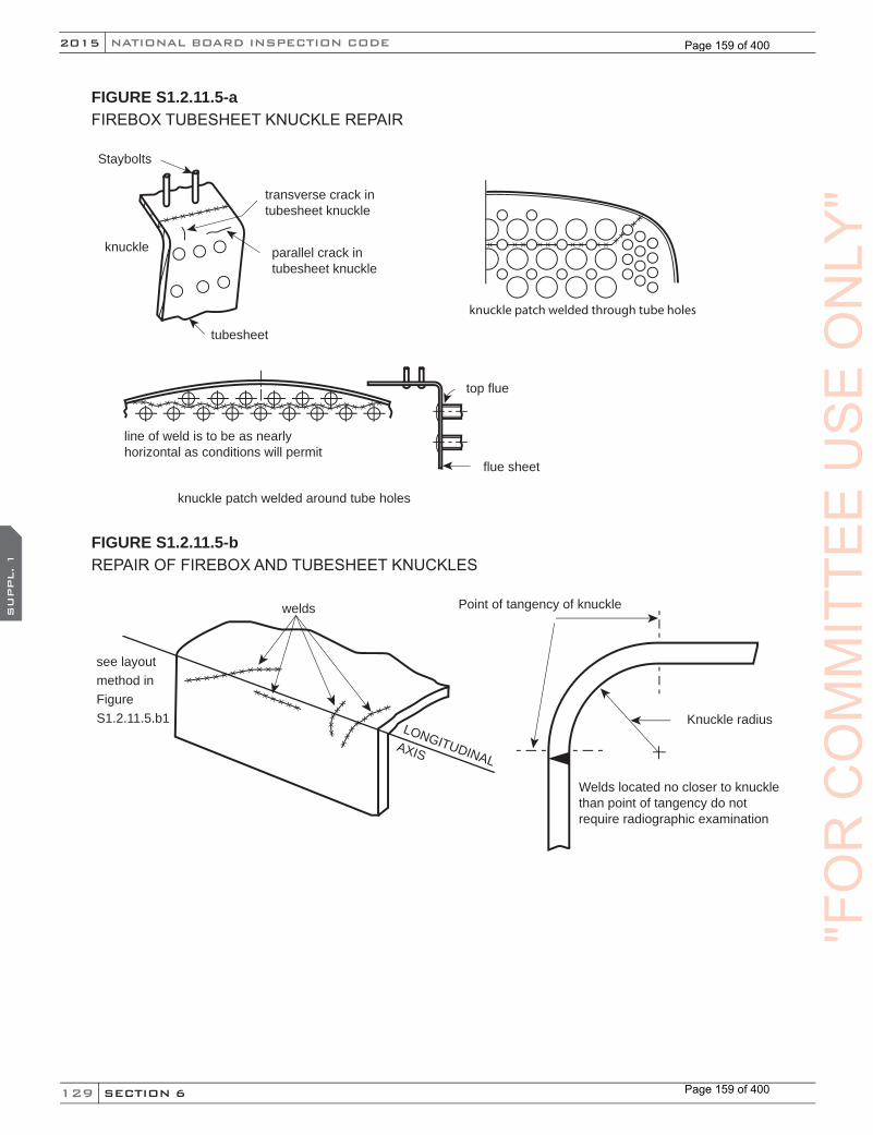
129
NATIONAL BOARD INSPECTION CODE2015
SECTION 6
SU
PPL. 1
FIGURE S1.2.11.5-aFIREBOX TUBESHEET KNUCKLE REPAIR
knuckle
Staybolts
transverse crack intubesheet knuckle
tubesheet
parallel crack intubesheet knuckle
knuckle patch welded through tube holes
flue sheet
top flue
line of weld is to be as nearlyhorizontal as conditions will permit
knuckle patch welded around tube holes
FIGURE S1.2.11.5-bREPAIR OF FIREBOX AND TUBESHEET KNUCKLES
Knuckle radius
Point of tangency of knuckle
Welds located no closer to knuckle than point of tangency do not require radiographic examination
welds
LONGITUDINALAXIS
see layout method in FigureS1.2.11.5.b1
"FO
RC
OM
MIT
TEE
US
EO
NLY
"
Page 159 of 400
Page 159 of 400
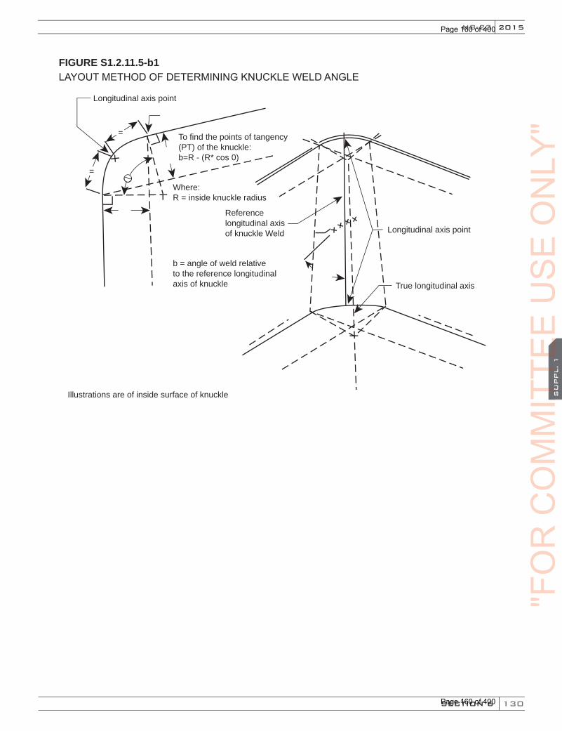
130
2015
SECTION 6
SU
PPL. 1
NB-23
FIGURE S1.2.11.5-b1LAYOUT METHOD OF DETERMINING KNUCKLE WELD ANGLE
To find the points of tangency (PT) of the knuckle: b=R - (R* cos 0)
Where:R = inside knuckle radius
b = angle of weld relative to the reference longitudinal axis of knuckle
Illustrations are of inside surface of knuckle
Referencelongitudinal axis of knuckle Weld Longitudinal axis point
True longitudinal axis
=
=
Longitudinal axis point
"FO
RC
OM
MIT
TEE
CO
MM
ITTE
EC
OM
MIT
TEE
SU
PPL. 1
CO
MM
ITTE
ES
UPPL. 1
US
EO
NLY
"
Page 160 of 400
Page 160 of 400

131
NATIONAL BOARD INSPECTION CODE2015
SECTION 6
SU
PPL. 1
FIGURE S1.2.11.5-cREPAIR OF FIREBOX AND TUBESHEET KNUCKLES
Stayed Patch Applied to Buttwelded Seam
Stayed Patch Applied to Riveted Seam
Repairs Requiring Radiographic Examination of Weld Seams
Staybolt rows point oftangency of knuckle
Knuckle
Tube or staybolt rows
Riveted Seam
Patch length
Patch length Patch length
Patch length
Weld seams located between stayboltrows and above first tube row or staybolt row
Weld seams located between tuberows below staybolt rows or tube rows
Weld seam located above firsttube row or staybolt row
Weld seam located between tube rows or staybolt rows
Weld seam located in knuckle Patch not supported by tubes, staybolts or rivets "F
OR
CO
MM
ITTE
EU
SE
ON
LY"
Page 161 of 400
Page 161 of 400
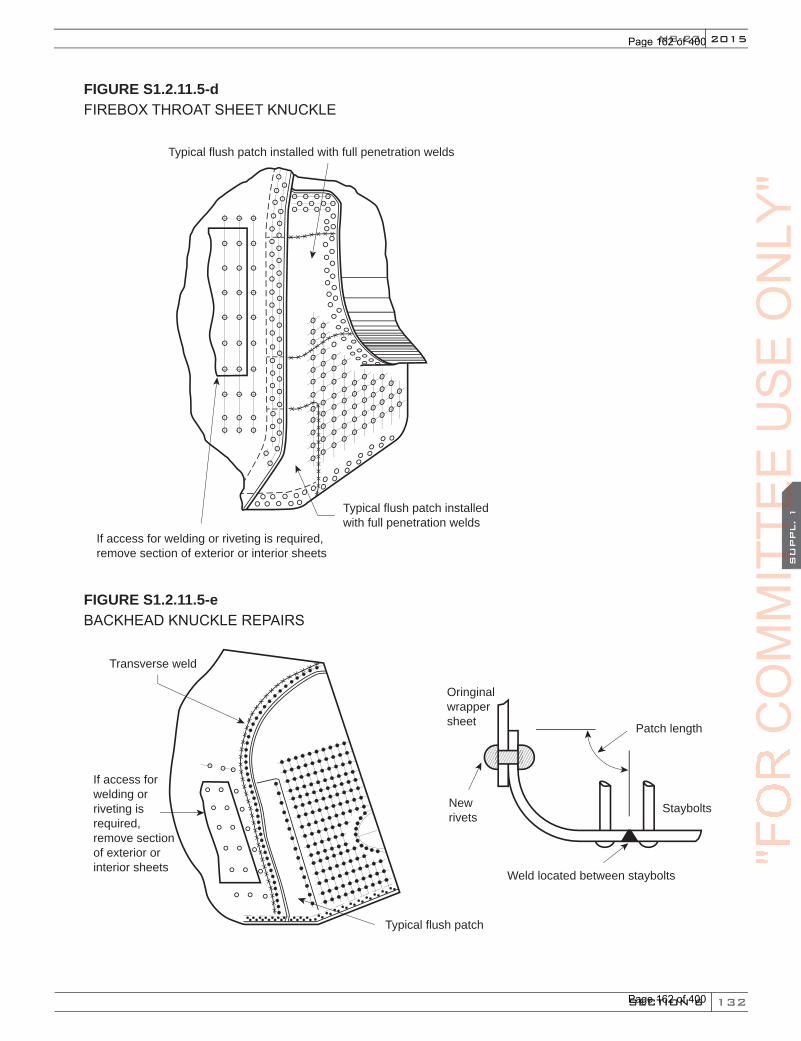
132
2015
SECTION 6
SU
PPL. 1
NB-23
FIGURE S1.2.11.5-dFIREBOX THROAT SHEET KNUCKLE
Typical flush patch installed with full penetration welds
Typical flush patch installed with full penetration welds
If access for welding or riveting is required, remove section of exterior or interior sheets
FIGURE S1.2.11.5-eBACKHEAD KNUCKLE REPAIRS
If access for welding or riveting is required,remove section of exterior or interior sheets
Patch length
Staybolts
Oringinalwrappersheet
Newrivets
Weld located between staybolts
Transverse weld
Typical flush patch
"FO
RC
OM
MIT
TEE
CO
MM
ITTE
EC
OM
MIT
TEE
SU
PPL. 1
CO
MM
ITTE
ES
UPPL. 1
US
EO
NLY
"
Page 162 of 400
Page 162 of 400
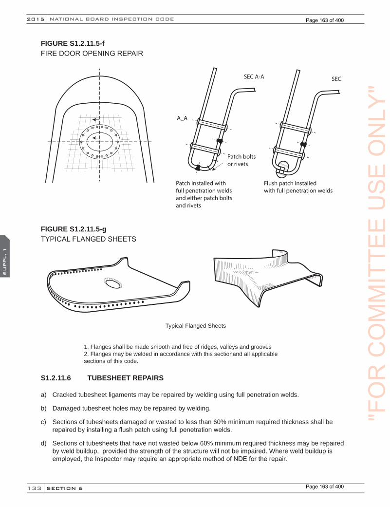
133
NATIONAL BOARD INSPECTION CODE2015
SECTION 6
SU
PPL. 1
FIGURE S1.2.11.5-fFIRE DOOR OPENING REPAIR
Patch installed with full penetration welds and either patch bolts and rivets
Patch bolts or rivets
A_A
SEC A-A
Flush patch installed with full penetration welds
SEC
FIGURE S1.2.11.5-gTYPICAL FLANGED SHEETS
Typical Flanged Sheets
1. Flanges shall be made smooth and free of ridges, valleys and grooves2. Flanges may be welded in accordance with this sectionand all applicable sections of this code.
S1.2.11.6 TUBESHEET REPAIRS
a) Cracked tubesheet ligaments may be repaired by welding using full penetration welds.
b) Damaged tubesheet holes may be repaired by welding.
c) Sections of tubesheets damaged or wasted to less than 60% minimum required thickness shall be repaired by installing a flush patch using full penetration welds.
d) Sections of tubesheets that have not wasted below 60% minimum required thickness may be repaired by weld buildup, provided the strength of the structure will not be impaired. Where weld buildup is employed, the Inspector may require an appropriate method of NDE for the repair.
"FO
RC
OM
MIT
TEE
US
EO
NLY
"
Page 163 of 400
Page 163 of 400
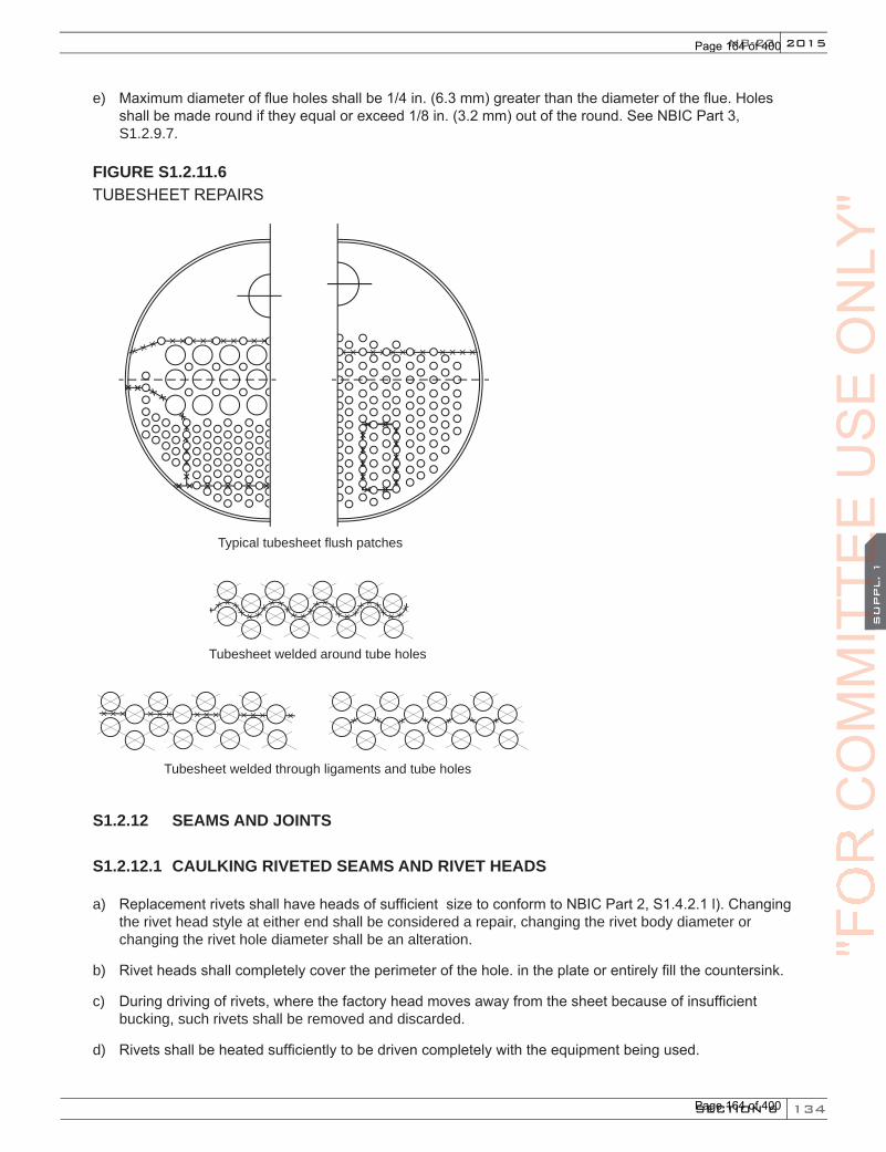
134
2015
SECTION 6
SU
PPL. 1
NB-23
e) Maximum diameter of flue holes shall be 1/4 in. (6.3 mm) greater than the diameter of the flue. Holes shall be made round if they equal or exceed 1/8 in. (3.2 mm) out of the round. See NBIC Part 3, S1.2.9.7.
FIGURE S1.2.11.6TUBESHEET REPAIRS
Typical tubesheet flush patches
Tubesheet welded around tube holes
Tubesheet welded through ligaments and tube holes
S1.2.12 SEAMS AND JOINTS
S1.2.12.1 CAULKING RIVETED SEAMS AND RIVET HEADS
a) Replacement rivets shall have heads of sufficient size to conform to NBIC Part 2, S1.4.2.1 l). Changing the rivet head style at either end shall be considered a repair, changing the rivet body diameter or changing the rivet hole diameter shall be an alteration.
b) Rivet heads shall completely cover the perimeter of the hole. in the plate or entirely fill the countersink.
c) During driving of rivets, where the factory head moves away from the sheet because of insufficient bucking, such rivets shall be removed and discarded.
d) Rivets shall be heated sufficiently to be driven completely with the equipment being used.
"FO
RC
OM
MIT
TEE
CO
MM
ITTE
EC
OM
MIT
TEE
SU
PPL. 1
CO
MM
ITTE
ES
UPPL. 1
US
EO
NLY
"
Page 164 of 400
Page 164 of 400
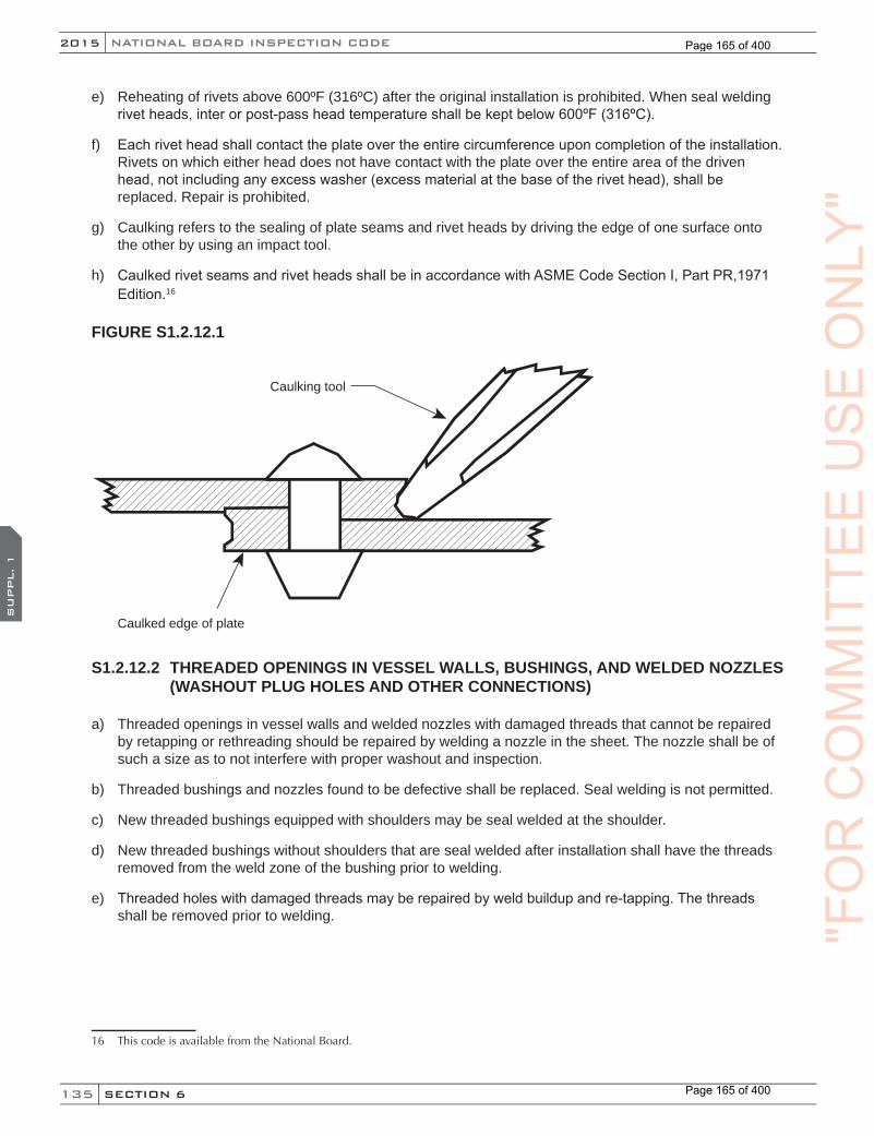
135
NATIONAL BOARD INSPECTION CODE2015
SECTION 6
SU
PPL. 1
e) Reheating of rivets above 600ºF (316ºC) after the original installation is prohibited. When seal welding rivet heads, inter or post-pass head temperature shall be kept below 600ºF (316ºC).
f) Each rivet head shall contact the plate over the entire circumference upon completion of the installation. Rivets on which either head does not have contact with the plate over the entire area of the driven head, not including any excess washer (excess material at the base of the rivet head), shall be replaced. Repair is prohibited.
g) Caulking refers to the sealing of plate seams and rivet heads by driving the edge of one surface onto the other by using an impact tool.
h) Caulked rivet seams and rivet heads shall be in accordance with ASME Code Section I, Part PR,1971 Edition.16
FIGURE S1.2.12.1
Caulking tool
Caulked edge of plate
S1.2.12.2 THREADED OPENINGS IN VESSEL WALLS, BUSHINGS, AND WELDED NOZZLES (WASHOUT PLUG HOLES AND OTHER CONNECTIONS)
a) Threaded openings in vessel walls and welded nozzles with damaged threads that cannot be repaired by retapping or rethreading should be repaired by welding a nozzle in the sheet. The nozzle shall be of such a size as to not interfere with proper washout and inspection.
b) Threaded bushings and nozzles found to be defective shall be replaced. Seal welding is not permitted.
c) New threaded bushings equipped with shoulders may be seal welded at the shoulder.
d) New threaded bushings without shoulders that are seal welded after installation shall have the threads removed from the weld zone of the bushing prior to welding.
e) Threaded holes with damaged threads may be repaired by weld buildup and re-tapping. The threads shall be removed prior to welding.
16 ThiscodeisavailablefromtheNationalBoard.
"FO
RC
OM
MIT
TEE
US
EO
NLY
"
Page 165 of 400
Page 165 of 400

136
2015
SECTION 6
SU
PPL. 1
NB-23
S1.2.13 FITTINGS AND GAGES
S1.2.13.1 WATER GAGE CONNECTION
a) Water gage glasses shall be applied so that the lowest water reading in the water gage glass of a horizontal firetube boiler on level track shall be at least 3 in. (75 mm) above the highest point of the tubes, flues, or crownsheet.
b) The bottom mounting for water gage glass (and for water column if used) must not extend less than 1-1/2 in. (38 mm) inside the boiler and beyond any obstacle immediately above it. The passage must be straight and approximately horizontal. Connections must be applied without pockets, traps, sags, or syphons. Tubular water gage glasses must be equipped with a protection shield.
c) Locomotive water gage glasses shall be provided with one top and one bottom shutoff cock and a means to illuminate each glass. Each top and bottom shutoff cock or valve shall be of such through flow construction as to prevent stoppage by deposits of sediments. Straight run globe valve of the ordinary type shall not be used on such connections. (See NBIC Part 3, Figure S1.2.13.1). The water gage glass connection and pipe connection shall be fitted with a drain cock or valve having an unrestricted opening of not less than 3/8 in. (10 mm) in diameter to facilitate cleaning.
d) The top and bottom water gage glass fittings are to be aligned, supported, and secured so as to maintain the alignment of the water gage glass.
e) The lower edge of the steam connection to a water column or water gage glass in the boiler shall not be below the highest visible water level in the water gage glass. There shall be no pockets, traps, sags, or syphons in the piping that will permit the accumulation of sediments.
f) The upper edge of the water connection to a water gage glass and the boiler shall not be above the lowest visible water level in the water gage glass. There shall be no pockets, traps, sags, or syphons in the connection.
FIGURE S1.2.13.1STRAIGHT RUN GLOBE VALVE NOT PERMITTED
"FO
RC
OM
MIT
TEE
CO
MM
ITTE
EC
OM
MIT
TEE
SU
PPL. 1
CO
MM
ITTE
ES
UPPL. 1
US
EO
NLY
"
Page 166 of 400
Page 166 of 400

137
NATIONAL BOARD INSPECTION CODE2015
SECTION 6
SU
PPL. 2
SUPPLEMENT 2 HISTORICAL BOILERS
S2.1 SCOPE
a) This supplement is provided as a guide to repair and alteration of historical steam boilers of riveted and/or welded construction not falling under the scope of Supplement 1. These historical steam boilers would include: steam tractors, traction engines, hobby steam boilers, portable steam boilers, and other such boilers that are being preserved, restored and maintained for demonstration, viewing, or educational purposes.
Note: This supplement is not to be used for steam locomotive boilers falling under the requirements of the Federal Railroad Administration (FRA). FRA rules for steam locomotive boilers are published in 49 CFR 230. Specific rules and special requirements for inspection, repairs, alterations, and storage of steam locomotive boilers are identified in NBIC Parts 2 and 3, Supplement 1.
b) The rules specified in this supplement shall be used in conjunction with the applicable rules in this Code. References specified or contained in this supplement may provide additional information to assist the user when applying the requirements of this supplement.
S2.2 INTRODUCTION
a) The following repair and alteration rules are minimum requirements for safe and satisfactory operation of historical boilers. Users of this supplement are cautioned that where complete details are not provided, the user is advised to seek technical guidance to provide good sound engineering evaluations and practices.
b) Where adopted by a Jurisdiction, these requirements are mandatory. Where a Jurisdiction establishes different requirements for historical boilers or where a conflict exists, the rules of the Jurisdiction prevail.
S2.3 RESPONSIBILITIES
The owner, user and/or operator are responsible for ensuring that the boiler meets all the requirements of the Jurisdiction where the boiler is operated, including inspections, repairs, licensing, operating certificates, permits, and operator training.
Note: It should be recognized that safety of these boilers is dependent upon the knowledge and training of the operator in proper use, repair, maintenance, and safe operation of each specific boiler proposed to be operated (See NBIC Part 2, Supplement 2).
S2.4 REPAIRS AND ALTERATIONS
Repairs and alterations to boilers of historical nature should be performed with consideration towards pre-serving the authenticity of original design, while at the same time ensuring that the boiler is safe to operate at the pressure allowed by NBIC Part 2, Supplement 2.
S2.5 CONSTRUCTION STANDARDS
Repairs and alterations shall conform to the requirements of the original construction standard insofar as pos-sible. If the original construction standard is unknown or unavailable, the boiler shall be considered a boiler of locomotive design and subject to the construction standard most applicable. The construction standard selected for the repair or alteration must meet the approval of the Jurisdiction.
"FO
RC
OM
MIT
TEE
US
EO
NLY
"
Page 167 of 400
Page 167 of 400
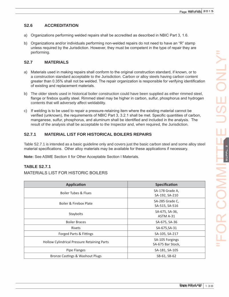
138
2015
SECTION 6
SU
PPL. 2
NB-23
S2.6 ACCREDITATION
a) Organizations performing welded repairs shall be accredited as described in NBIC Part 3, 1.6.
b) Organizations and/or individuals performing non-welded repairs do not need to have an “R” stamp unless required by the Jurisdiction. However, they must be competent in the type of repair they are performing.
S2.7 MATERIALS
a) Materials used in making repairs shall conform to the original construction standard, if known, or to a construction standard acceptable to the Jurisdiction. Carbon or alloy steels having carbon content greater than 0.35% shall not be welded. The repair organization is responsible for verifying identification of existing and replacement materials.
b) The older steels used in historical boiler construction could have been supplied as either rimmed steel, flange or firebox quality steel. Rimmed steel may be higher in carbon, sulfur, phosphorus and hydrogen contents that will adversely affect weldability.
c) If welding is to be used to repair a pressure-retaining item where the existing material cannot be verified (unknown), the requirements of NBIC Part 3, 3.2.1 shall be met. Specific quantities of carbon, manganese, sulfur, phosphorus, and aluminum shall be identified and included in the analysis. The result of the analysis shall be acceptable to the Inspector and, when required, the Jurisdiction.
S2.7.1 MATERIAL LIST FOR HISTORICAL BOILERS REPAIRS
Table S2.7.1 is intended as a basic guideline only and covers just the basic carbon steel and some alloy steel material specifications. Other alloy materials may be available for these applications if necessary.
Note: See ASME Section II for Other Acceptable Section I Materials.
TABLE S2.7.1 MATERIALS LIST FOR HISTORIC BOILERS
Application Specification
Boiler Tubes & Flues SA-178 Grade A, SA-192, SA-210
Boiler & Firebox Plate SA-285 Grade C, SA-515, SA-516
Staybolts SA-675, SA-36, ASTM A-31
Boiler Braces SA-675, SA-36Rivets SA-675,SA-31
Forged Parts & Fittings SA-105, SA-217
Hollow Cylindrical Pressure Retaining Parts SA-105 Forgings SA-675 Bar Stock,
Pipe Flanges SA-181, SA-105Bronze Castings & Washout Plugs SB-61, SB-62
"FO
RC
OM
MIT
TEE
CO
MM
ITTE
EC
OM
MIT
TEE
SU
PPL. 2
CO
MM
ITTE
ES
UPPL. 2
US
EO
NLY
"
Page 168 of 400
Page 168 of 400

139
NATIONAL BOARD INSPECTION CODE2015
SECTION 6
SU
PPL. 2
a) SA-516 steel is recommended for firebox repairs. It is a fine grain steel that accepts flanging and bending with less tendency to crack than course grain steels such as SA-515 or SA-285 Grade C. Coarse grain steels have, on occasion, been found to crack or split after complicated flanging, bending, and forming.
b) SA-36 is not to be used to make any pressure-retaining part such as shells.
c) When rivets are made from SA-675, the finished rivets must meet the physical and test requirements of the original ASME rivet specification ASTM A-31 Grade A or B.
d) When staybolt material tensile strength is greater than that of the firebox sheets, the firebox sheets deflect instead of the staybolts, which can result in the sheets developing cracks and leaking staybolts. In addition, high tensile strength steels are difficult to drive.
S2.7.2 REPLACEMENT PARTS
Replacement pressure parts formed by casting, forging, or die forming, and on which no welding has been performed shall be supplied as material. Such parts shall be marked with the material identification required by the construction standard used for the repair. Replacement pressure parts fabricated by welding shall be manufactured by an organization certified as required by the construction standard used for the repair. When it is not possible or practical for a manufacturer to supply replacement parts fabricated by welding, an organi-zation accredited as described in NBIC Part 3, 1.6 may fabricate the part with the approval of the Jurisdiction.
S2.8 WELDED REPAIR INSPECTION
Prior to commencing any welded repairs to the pressure boundaries of historical boilers, the repair organiza-tion shall obtain an Inspector’s approval of the proposed repair. The Inspector shall be an employee of either a Jurisdiction, as defined in NBIC Part 3, Section 9, Glossary, or of the Authorized Inspection Agency con-tracted by the repair organization. The Inspector shall ensure the repairs are performed in accordance with the approved construction standard, and shall verify any nondestructive examinations or witness pressure testing of the completed repair.
S2.9 WELDING
Welding shall be performed in accordance with the requirements of the approved construction standard in consultation with the Inspector. A repair organization accredited as described in NBIC Part 3, 1.6 may use the Standard Welding Procedure Specifications shown in 2.3, as applicable. Welders shall be qualified for the welding processes used. Qualification shall be in accordance with the approved construction standard, or ASME Section IX.
S2.10 HEAT TREATMENT
a) Preheat and postweld heat treatment may be used to assist in completion of the welded joint. Consideration should be given to the percentage of carbon content and to the thickness of the boiler materials to be welded. Required preheat and PWHT temperatures shall be specified on the qualified Welding Procedure Specification being used.
b) Postweld heat treatment shall be performed as required by the accepted construction standard, in accordance with written procedures acceptable to the Inspector.
c) Alternative postweld heat treatment methods may be used with the Inspector’s approval. Weldingmethods that may be used as alternatives to postweld heat treatment when PWHT cannot be performed are limited to increased preheat temperatures and controlled temper bead methods. (See NBIC Part 3, 2.5.3)
"FO
RC
OM
MIT
TEE
US
EO
NLY
"
Page 169 of 400
Page 169 of 400

140
2015
SECTION 6
SU
PPL. 2
NB-23
S2.11 NONDESTRUCTIVE EXAMINATION
The Inspector may require nondestructive examination (RT, PT, MT, UT, and VT) as necessary to ensure satisfactory welded repairs have been accomplished.
S2.12 DOCUMENTATION
Organizations performing repairs to historic boilers shall document the repair or alteration on Form R-1 or R-2, as applicable. Permanent documentation detailing repairs or alterations should be retained by the owner in permanent boiler records such as an operator log book.
S2.13 REPAIR METHODS
a) Before performing any welding activity, consideration shall be given to ensure the weldability of historical boiler materials. Materials used for patches shall be made from material that is at least equal in quality and strength to the original material.
b) Before a repair is made to a defect in a welded joint or base metal, care should be taken to investigate its cause and to determine its extent and likelihood of recurrence.
c) A repair of a defect, such as a crack in a welded joint or base material, shall not be made until the defect has been removed. A suitable nondestructive examination method such as magnetic particle (MT) or liquid penetrant (PT) may be necessary to assure complete removal of the defect. If the defect penetrates the full thickness of the material, the repair shall be made with a complete penetration weld such as a double buttweld or a single buttweld with or without backing. Where circumstances indicate that the defect is likely to recur, consideration should be given to removing the defective area and installing a flush patch or taking other acceptable, corrective measures. A repair of a bulge or blister shall be made if a bulge or blister will affect the pressure retaining capability of the plate or tube or when evidence of leakage is noted. Defects such as cracks, grooving, and wastage may be repaired by weld buildup, welded repair, a welded flush patch, or a riveted patch as appropriate.
d) Welded repairs at or near riveted seams requiring preheating or postweld heat treatment shall be carefully made to prevent loosening in the riveted seams, especially when localized heating is used. Where necessary to control expansion or to gain access for welding, rivets at the defective section and to each side of it may be removed. Reuse of rivets is prohibited.
S2.13.1 REPAIR OF THREADED STAYBOLT HOLES
Staybolt holes may be repaired by welding, reaming, re-tapping to a larger size, or by installing a flush patch. (See NBIC Part 3, Figure S2.13.1). If the staybolt hole was threaded and is to be repaired by welding, the threads shall be removed prior to welding.
"FO
RC
OM
MIT
TEE
CO
MM
ITTE
EC
OM
MIT
TEE
SU
PPL. 2
CO
MM
ITTE
ES
UPPL. 2
US
EO
NLY
"
Page 170 of 400
Page 170 of 400
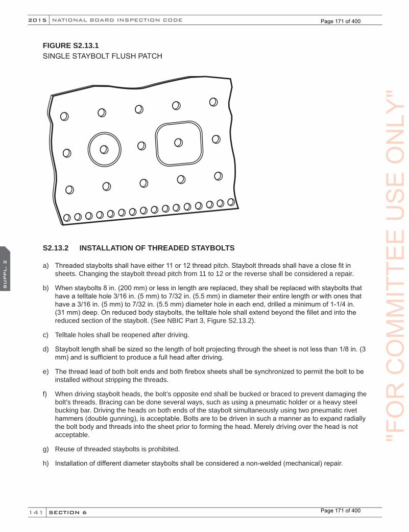
141
NATIONAL BOARD INSPECTION CODE2015
SECTION 6
SU
PPL. 2
FIGURE S2.13.1SINGLE STAYBOLT FLUSH PATCH
S2.13.2 INSTALLATION OF THREADED STAYBOLTS
a) Threaded staybolts shall have either 11 or 12 thread pitch. Staybolt threads shall have a close fit in sheets. Changing the staybolt thread pitch from 11 to 12 or the reverse shall be considered a repair.
b) When staybolts 8 in. (200 mm) or less in length are replaced, they shall be replaced with staybolts that have a telltale hole 3/16 in. (5 mm) to 7/32 in. (5.5 mm) in diameter their entire length or with ones that have a 3/16 in. (5 mm) to 7/32 in. (5.5 mm) diameter hole in each end, drilled a minimum of 1-1/4 in. (31 mm) deep. On reduced body staybolts, the telltale hole shall extend beyond the fillet and into the reduced section of the staybolt. (See NBIC Part 3, Figure S2.13.2).
c) Telltale holes shall be reopened after driving.
d) Staybolt length shall be sized so the length of bolt projecting through the sheet is not less than 1/8 in. (3 mm) and is sufficient to produce a full head after driving.
e) The thread lead of both bolt ends and both firebox sheets shall be synchronized to permit the bolt to be installed without stripping the threads.
f) When driving staybolt heads, the bolt’s opposite end shall be bucked or braced to prevent damaging the bolt’s threads. Bracing can be done several ways, such as using a pneumatic holder or a heavy steel bucking bar. Driving the heads on both ends of the staybolt simultaneously using two pneumatic rivet hammers (double gunning), is acceptable. Bolts are to be driven in such a manner as to expand radially the bolt body and threads into the sheet prior to forming the head. Merely driving over the head is not acceptable.
g) Reuse of threaded staybolts is prohibited.
h) Installation of different diameter staybolts shall be considered a non-welded (mechanical) repair.
"FO
RC
OM
MIT
TEE
US
EO
NLY
"
Page 171 of 400
Page 171 of 400

142
2015
SECTION 6
SU
PPL. 2
NB-23
FIGURE S2.13.2THREADED STAYBOLT
Telltale holes
Full length thread staybolt
Reduced body staybolt
Telltale shall extend beyond tangent point of fillet radius
Telltale shall be at least 1-1/4 inch deep
S2.13.3 SEAL WELDING OF THREADED STAYBOLTS
a) Replacement threaded staybolts may be seal welded before or after driving. (See NBIC Part 3, Figure S2.13.3).
b) Existing threaded staybolts that leak shall be repaired and may be seal welded. When used, seal welding shall not be the sole means of repair. Inspection must be done to ensure the material adjacent to the staybolt has not been materially weakened by deterioration or wasting away before welding can be performed.
"FO
RC
OM
MIT
TEE
CO
MM
ITTE
EC
OM
MIT
TEE
SU
PPL. 2
CO
MM
ITTE
ES
UPPL. 2
US
EO
NLY
"
Page 172 of 400
Page 172 of 400

143
NATIONAL BOARD INSPECTION CODE2015
SECTION 6
SU
PPL. 2
FIGURE S2.13.3SEAL WELDING STAYBOLTS
Staybolt head seal welded before driving
Staybolt head seal welded after driving
S2.13.4 INSTALLATION OF WELDED STAYBOLTS
a) The installation of unthreaded staybolts using full penetration welds is permissible. (See NBIC Part 3, Figure S2.13.4).
b) Threaded stays may be replaced by welded-in stays provided that, in the judgement of the Inspector, the material adjacent to the staybolt has not been materially weakened by deterioration or wasting away. If staybolt hole is threaded, the threads shall be removed prior to welding.
c) Staybolts shorter than 8 in. (200 mm) in length shall have telltale holes. Telltale hole diameter shall be 3/16 in. (5 mm) to 7/32 in. (5.5 mm) in diameter and at least 1-1/4 in. (31 mm) deep in the outer end. On reduced body staybolts, the telltale hole shall extend beyond the fillet and into the reduced section of the staybolt. Staybolts should have through telltale holes, which are preferred.
d) Reuse of welded staybolts is prohibited.
e) Installation of different diameter staybolts shall be considered a repair.
"FO
RC
OM
MIT
TEE
US
EO
NLY
"
Page 173 of 400
Page 173 of 400
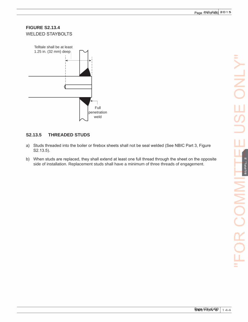
144
2015
SECTION 6
SU
PPL. 2
NB-23
FIGURE S2.13.4WELDED STAYBOLTS
Telltale shall be at least 1.25 in. (32 mm) deep
Fullpenetration
weld
S2.13.5 THREADED STUDS
a) Studs threaded into the boiler or firebox sheets shall not be seal welded (See NBIC Part 3, Figure S2.13.5).
b) When studs are replaced, they shall extend at least one full thread through the sheet on the opposite side of installation. Replacement studs shall have a minimum of three threads of engagement.
"FO
RC
OM
MIT
TEE
CO
MM
ITTE
EC
OM
MIT
TEE
SU
PPL. 2
CO
MM
ITTE
ES
UPPL. 2
US
EO
NLY
"
Page 174 of 400
Page 174 of 400
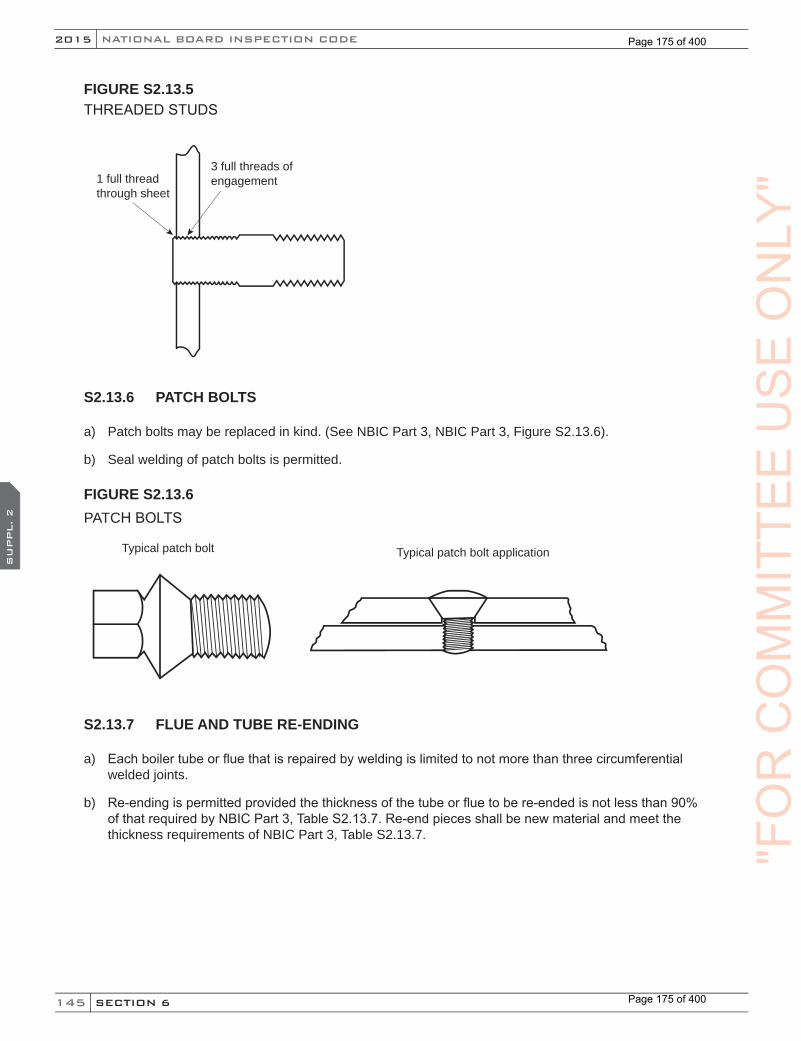
145
NATIONAL BOARD INSPECTION CODE2015
SECTION 6
SU
PPL. 2
FIGURE S2.13.5THREADED STUDS
1 full thread through sheet
3 full threads of engagement
S2.13.6 PATCH BOLTS
a) Patch bolts may be replaced in kind. (See NBIC Part 3, NBIC Part 3, Figure S2.13.6).
b) Seal welding of patch bolts is permitted.
FIGURE S2.13.6PATCH BOLTS
Typical patch bolt Typical patch bolt application
S2.13.7 FLUE AND TUBE RE-ENDING
a) Each boiler tube or flue that is repaired by welding is limited to not more than three circumferential welded joints.
b) Re-ending is permitted provided the thickness of the tube or flue to be re-ended is not less than 90% of that required by NBIC Part 3, Table S2.13.7. Re-end pieces shall be new material and meet the thickness requirements of NBIC Part 3, Table S2.13.7. "F
OR
CO
MM
ITTE
EU
SE
ON
LY"
Page 175 of 400
Page 175 of 400

146
2015
SECTION 6
SU
PPL. 2
NB-23
TABLE S2.13.7MAXIMUM ALLOWABLE WORKING PRESSURES FOR STEEL TUBES OR FLUES FOR FIRETUBE BOILERS FOR DIFFERENT DIAMETERS AND GAGES OF TUBES CONFORMING TO THE REQUIREMENTS OF SPEC. SA-176, SA-192, SA-209, OR SA 210
Outsidediameter oftube, inches
D
Minimum gage, Birmingham Wire Gage (BWG), inches13
t = 0.09512
t = 0.10911
t = 0.12010
t = 0.1349
t = 0.1488
t = 0.1657
t = 0.1806
t = 0.2035
t = 0.2204
t = 0.2381 470 690 — — — — — — — —
1-1/2 320 460 570 720 860 — — — — —1-3/4 270 400 490 620 740 890 — — — —
2 240 350 430 540 650 780 900 — — —2-1/4 210 310 380 480 580 690 800 960 — —2-1/2 190 280 350 430 520 620 720 860 970 1,080
3 160 230 290 360 430 520 600 720 810 9003-1/4 — 210 270 330 400 480 550 660 740 8303-1/2 — 200 250 310 370 450 510 620 690 770
4 — 180 220 270 330 390 450 540 610 6804-1/2 — 160 190 240 290 350 400 480 540 600
5 — — 180 220 260 310 360 430 490 5405-3/8 — — 160 200 240 290 340 400 450 5005-1/2 — — — 200 240 290 330 390 440 490
6 — — — 180 220 260 300 360 410 450P = {(t–0.65)/D} x 15550 where P = maximum allowable working pressure, pounds per square inch,
t = minimum wall thickness, inches, D = outside diameter of tubes, inches.
For pressures below those given in the table, the gage thickness shall be not less than the minimum given in the table. Calculated values of pressure have been rounded to the next higher unit of 10 psi.
"FO
RC
OM
MIT
TEE
CO
MM
ITTE
EC
OM
MIT
TEE
SU
PPL. 2
CO
MM
ITTE
ES
UPPL. 2
US
EO
NLY
"
Page 176 of 400
Page 176 of 400

147
NATIONAL BOARD INSPECTION CODE2015
SECTION 6
SU
PPL. 2
TABLE S2.13.7MMAXIMUM ALLOWABLE WORKING PRESSURES FOR STEEL TUBES OR FLUES FOR FIRETUBE BOILERS FOR DIFFERENT DIAMETERS AND GAGES OF TUBES TO THE REQUIREMENTS OF SPEC. SA-176, SA-192, OR SA 210
Outsidediameter oftube, mm
D
Minimum gage, Birmingham Wire Gage (BWG), to mm13
t = 2.412
t = 2.811
t = 3.010
t = 3.49
t = 3.88
t = 4.27
t = 4.66
t = 5.25
t = 5.64
t = 6.025 3,250 4,950 — — — — — — — —40 2,150 3,250 3,850 4,950 6,100 — — — — —45 1,850 2,800 3,300 4,300 5,250 6,250 — — — —50 1,650 2,450 2,850 3,700 4,550 5,350 6,200 — — —60 1,450 2,200 2,550 3,300 4,050 4,800 5,550 6,700 — —65 1,300 1,950 2,300 2,950 3,600 4,300 4,950 5,950 6,650 7,30075 1,100 1,650 1,950 2,500 3,050 3,600 4,200 5,000 5,600 6,15085 — 1,500 1,750 2,300 2,800 3,300 3,850 4,600 5,100 5,65090 — 1,400 1,650 2,150 2,600 3,100 3,550 4,300 4,750 5,250
100 — 1,250 1,450 1,850 2,300 2,700 3,100 3,750 4,150 5,600115 — 1,100 1,300 1,650 2,050 2,400 2,800 3,300 3,750 4,100125 — — 1,150 1,500 1,850 2,200 2,500 3,000 3,350 3,700135 — — 1,100 1,400 1,700 2,000 2,350 2,800 3,100 3,400140 — — — 1,350 1,650 2,000 2,300 2,750 3,050 3,350150 — — — 1,250 1,550 1,800 2,100 2,500 2,800 3,100
P = {(t–1.65)/D} x 107000 where P = maximum allowable working pressure, kilopascals (kPa), t = minimum wall thickness, mm,
D = outside diameter of tubes, mm.For pressures below those given in the table, the gage thickness shall be not less than the minimum given in the table. Calculated values of pressure have been rounded to the next higher unit of 50 kPa.
S2.13.8 FLUE AND TUBE INSTALLATION
a) When boiler tubes and flues are replaced, the MAWP of the boiler must not exceed the MAWP of the tube or flue per Table S2.13.7.
b) The boiler shall have the ends of the tubes firmly rolled and beaded, or rolled and welded around the edge of the tube. (See NBIC Part 3, Figure S2.13.8). Tube ends attached by rolling and welding are subject to the following provisions:
1) The tube sheet hole may be beveled or recessed to a depth at least equal to the thickness of the tubes. Where the hole is beveled or recessed, the projection of the tube beyond the tube sheet shall not exceed a distance equal to the tube thickness. The depth of any bevel or recess shall not be less than the tube thickness or 1/8 in. (3 mm), whichever is greater, nor more than one-third of the tube sheet thickness. (See NBIC Part 3, Figure S2.13.8 f) and g)).
2) Where no bevel or recess is employed, the tube shall extend beyond the tube sheet not less than a distance equal to the tube thickness, nor more than twice the tube thickness. (See NBIC Part 3, Figure S2.13.8 e)).
"FO
RC
OM
MIT
TEE
US
EO
NLY
"
Page 177 of 400
Page 177 of 400
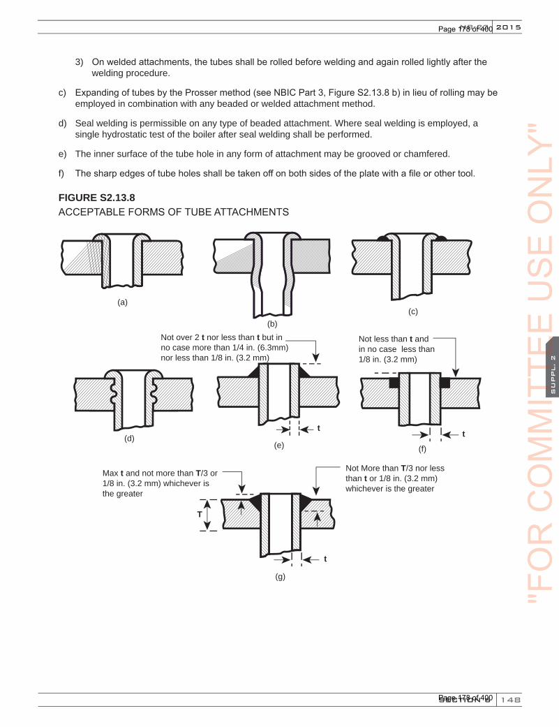
148
2015
SECTION 6
SU
PPL. 2
NB-23
3) On welded attachments, the tubes shall be rolled before welding and again rolled lightly after the welding procedure.
c) Expanding of tubes by the Prosser method (see NBIC Part 3, Figure S2.13.8 b) in lieu of rolling may be employed in combination with any beaded or welded attachment method.
d) Seal welding is permissible on any type of beaded attachment. Where seal welding is employed, a single hydrostatic test of the boiler after seal welding shall be performed.
e) The inner surface of the tube hole in any form of attachment may be grooved or chamfered.
f) The sharp edges of tube holes shall be taken off on both sides of the plate with a file or other tool.
FIGURE S2.13.8ACCEPTABLE FORMS OF TUBE ATTACHMENTS
tt
(a)(c)
(d)(e) (f)
(b)Not over 2 t nor less than t but in no case more than 1/4 in. (6.3mm) nor less than 1/8 in. (3.2 mm)
T
t
(g)
Max t and not more than T/3 or 1/8 in. (3.2 mm) whichever is the greater
Not More than T/3 nor less than t or 1/8 in. (3.2 mm) whichever is the greater
Not less than t and in no case less than 1/8 in. (3.2 mm)
"FO
RC
OM
MIT
TEE
CO
MM
ITTE
EC
OM
MIT
TEE
SU
PPL. 2
CO
MM
ITTE
ES
UPPL. 2
US
EO
NLY
"
Page 178 of 400
Page 178 of 400
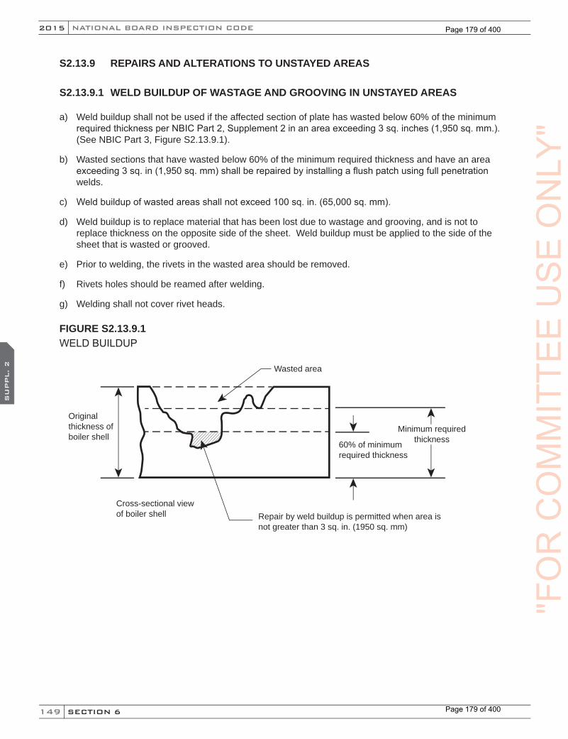
149
NATIONAL BOARD INSPECTION CODE2015
SECTION 6
SU
PPL. 2
S2.13.9 REPAIRS AND ALTERATIONS TO UNSTAYED AREAS
S2.13.9.1 WELD BUILDUP OF WASTAGE AND GROOVING IN UNSTAYED AREAS
a) Weld buildup shall not be used if the affected section of plate has wasted below 60% of the minimum required thickness per NBIC Part 2, Supplement 2 in an area exceeding 3 sq. inches (1,950 sq. mm.). (See NBIC Part 3, Figure S2.13.9.1).
b) Wasted sections that have wasted below 60% of the minimum required thickness and have an area exceeding 3 sq. in (1,950 sq. mm) shall be repaired by installing a flush patch using full penetration welds.
c) Weld buildup of wasted areas shall not exceed 100 sq. in. (65,000 sq. mm).
d) Weld buildup is to replace material that has been lost due to wastage and grooving, and is not to replace thickness on the opposite side of the sheet. Weld buildup must be applied to the side of the sheet that is wasted or grooved.
e) Prior to welding, the rivets in the wasted area should be removed.
f) Rivets holes should be reamed after welding.
g) Welding shall not cover rivet heads.
FIGURE S2.13.9.1WELD BUILDUP
Originalthickness of boiler shell
Wasted area
Cross-sectional viewof boiler shell Repair by weld buildup is permitted when area is
not greater than 3 sq. in. (1950 sq. mm)
60% of minimumrequired thickness
Minimum required thickness
"FO
RC
OM
MIT
TEE
US
EO
NLY
"
Page 179 of 400
Page 179 of 400
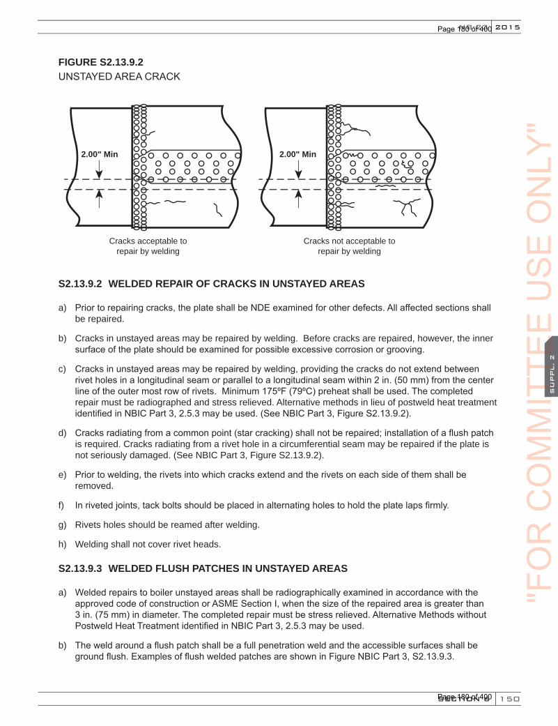
150
2015
SECTION 6
SU
PPL. 2
NB-23
FIGURE S2.13.9.2UNSTAYED AREA CRACK
Cracks acceptable torepair by welding
Cracks not acceptable torepair by welding
2.00" Min 2.00" Min
S2.13.9.2 WELDED REPAIR OF CRACKS IN UNSTAYED AREAS
a) Prior to repairing cracks, the plate shall be NDE examined for other defects. All affected sections shall be repaired.
b) Cracks in unstayed areas may be repaired by welding. Before cracks are repaired, however, the inner surface of the plate should be examined for possible excessive corrosion or grooving.
c) Cracks in unstayed areas may be repaired by welding, providing the cracks do not extend between rivet holes in a longitudinal seam or parallel to a longitudinal seam within 2 in. (50 mm) from the center line of the outer most row of rivets. Minimum 175ºF (79ºC) preheat shall be used. The completed repair must be radiographed and stress relieved. Alternative methods in lieu of postweld heat treatment identified in NBIC Part 3, 2.5.3 may be used. (See NBIC Part 3, Figure S2.13.9.2).
d) Cracks radiating from a common point (star cracking) shall not be repaired; installation of a flush patch is required. Cracks radiating from a rivet hole in a circumferential seam may be repaired if the plate is not seriously damaged. (See NBIC Part 3, Figure S2.13.9.2).
e) Prior to welding, the rivets into which cracks extend and the rivets on each side of them shall be removed.
f) In riveted joints, tack bolts should be placed in alternating holes to hold the plate laps firmly.
g) Rivets holes should be reamed after welding.
h) Welding shall not cover rivet heads.
S2.13.9.3 WELDED FLUSH PATCHES IN UNSTAYED AREAS
a) Welded repairs to boiler unstayed areas shall be radiographically examined in accordance with the approved code of construction or ASME Section I, when the size of the repaired area is greater than 3 in. (75 mm) in diameter. The completed repair must be stress relieved. Alternative Methods without Postweld Heat Treatment identified in NBIC Part 3, 2.5.3 may be used.
b) The weld around a flush patch shall be a full penetration weld and the accessible surfaces shall be ground flush. Examples of flush welded patches are shown in Figure NBIC Part 3, S2.13.9.3.
"FO
RC
OM
MIT
TEE
CO
MM
ITTE
EC
OM
MIT
TEE
SU
PPL. 2
CO
MM
ITTE
ES
UPPL. 2
US
EO
NLY
"
Page 180 of 400
Page 180 of 400
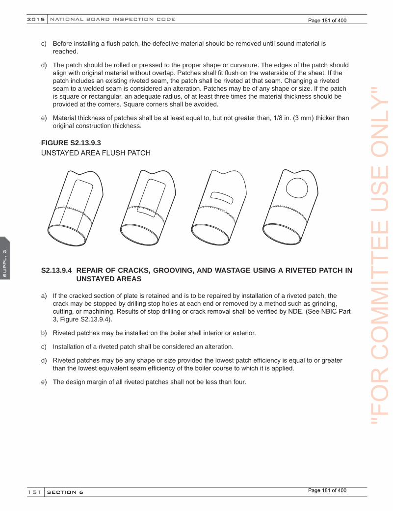
151
NATIONAL BOARD INSPECTION CODE2015
SECTION 6
SU
PPL. 2
c) Before installing a flush patch, the defective material should be removed until sound material is reached.
d) The patch should be rolled or pressed to the proper shape or curvature. The edges of the patch should align with original material without overlap. Patches shall fit flush on the waterside of the sheet. If the patch includes an existing riveted seam, the patch shall be riveted at that seam. Changing a riveted seam to a welded seam is considered an alteration. Patches may be of any shape or size. If the patch is square or rectangular, an adequate radius, of at least three times the material thickness should be provided at the corners. Square corners shall be avoided.
e) Material thickness of patches shall be at least equal to, but not greater than, 1/8 in. (3 mm) thicker than original construction thickness.
FIGURE S2.13.9.3UNSTAYED AREA FLUSH PATCH
S2.13.9.4 REPAIR OF CRACKS, GROOVING, AND WASTAGE USING A RIVETED PATCH IN UNSTAYED AREAS
a) If the cracked section of plate is retained and is to be repaired by installation of a riveted patch, the crack may be stopped by drilling stop holes at each end or removed by a method such as grinding, cutting, or machining. Results of stop drilling or crack removal shall be verified by NDE. (See NBIC Part 3, Figure S2.13.9.4).
b) Riveted patches may be installed on the boiler shell interior or exterior.
c) Installation of a riveted patch shall be considered an alteration.
d) Riveted patches may be any shape or size provided the lowest patch efficiency is equal to or greater than the lowest equivalent seam efficiency of the boiler course to which it is applied.
e) The design margin of all riveted patches shall not be less than four."F
OR
CO
MM
ITTE
EU
SE
ON
LY"
Page 181 of 400
Page 181 of 400

152
2015
SECTION 6
SU
PPL. 2
NB-23
FIGURE S2.13.9.4RIVETED BOILER SHELL PATCH
Diagonal riveted patch Circular riveted patch
Typical riveted patch installationPatch
Boiler shell
S2.13.9.5 BARREL REPLACEMENT
An entire course of a barrel may be replaced as a repair provided that:
a) The replacement material is code-accepted material (see NBIC Part 3, S2.7.1) that has a nominal composition and strength that is equal to or greater than the original, and is suitable for the intended service.
b) The minimum required thickness shall be at least equal to the original material thickness. The original thickness may be determined from the original Manufacturer’s Data Report, original drawings, or by measuring the original material thickness in an area unaffected by corrosion.
c) The longitudinal joint efficiency of the new barrel course meets or exceeds the original design/ construction;
d) All doubling/reinforcing plates, stays and openings in the original barrel are duplicated or retained on the new barrel and installed in a manner that meets or exceeds the original design/construction;
e) All attachments and connections with other portions of the boiler are attached in the same manner as the original;
f) The boiler will not be re-rated at a MAWP greater than the original design MAWP; and
g) If all of the above requirements are not met, then the replacement will be considered an alteration and must follow the requirements of NBIC Part 3, 3.4 and S2.13.10 repairs and alterations to stayed areas.
(15)
"FO
RC
OM
MIT
TEE
CO
MM
ITTE
EC
OM
MIT
TEE
SU
PPL. 2
CO
MM
ITTE
ES
UPPL. 2
(15)
CO
MM
ITTE
E
(15)
US
EO
NLY
"
Page 182 of 400
Page 182 of 400

153
NATIONAL BOARD INSPECTION CODE2015
SECTION 6
SU
PPL. 2
S2.13.10 REPAIRS AND ALTERATIONS TO STAYED AREAS
S2.13.10.1 WELD BUILDUP OF WASTAGE AND GROOVING IN STAYED AREAS
Requirements specified in NBIC Part 3, S2.13.9.1 shall apply with the following additional requirements identified below:
a) Prior to welding, the rivets and or staybolts in the wasted areas should be removed.
b) Threaded staybolt holes shall be retapped after welding.
c) Welding shall not cover rivet or staybolt heads.
S2.13.10.2 WELDED REPAIR OF CRACKS IN STAYED AREAS
Requirements specified in NBIC Part 3, S2.13.9.2 shall apply with the following additional requirements identified below:
a) If the crack extends into a staybolt hole, the staybolt shall be removed prior to making the repair.
b) Threaded staybots shall be retapped after welding.
S2.13.10.3 WELDED FLUSH PATCHES IN STAYED AREAS
The requirements identified in NBIC Part 3, S2.13.9.3 shall apply with the additional requirements specified below:
a) Patches may be any shape provided they are adequately supported by staybolts, rivets, tubes, or other forms of construction. Patches on stayed surfaces should be designed so weld seams pass between staybolt rows. (See NBIC Part 3, Figure S2.13.10.3-a);
b) Patches are to be flush type, using full penetration welds. If the load on the patch is carried by other forms of construction, such as staybolts, rivets, or tubes, radiographic examination of the welds is not required;
c) Staybolts and rivets should be installed after welding of patch is completed. Reuse of staybolts and rivets is prohibited; and
d) Weld seams parallel to a knuckle shall be located no closer to the knuckle than the point of tangency of the knuckle unless the weld is radiographically examined. Weld seams not located in the knuckle are preferred. (See NBIC Part 3, Figure S2.13.10.3-b).
"FO
RC
OM
MIT
TEE
US
EO
NLY
"
Page 183 of 400
Page 183 of 400

154
2015
SECTION 6
SU
PPL. 2
NB-23
FIGURE S2.13.10.3-aSTAYED AREA FLUSH PATCH
FIGURE S2.13.10.3-bKNUCKLE POINT OF TANGENCY
Point of tangency of knuckle
Knuckle radius
S2.13.10.4 REPAIR OF STAYED FIREBOX SHEETS GROOVED OR WASTED AT THE MUDRING
a) Mudrings of the Ogee style (knuckle) shall be repaired in accordance with NBIC Part 3, S2.13.11.
b) For mudrings of the locomotive style (See NBIC Part 3, Figure S2.13.10.4-a), weld buildup shall not be used if the affected section of plate has wasted below 60% of the minimum required thickness per Part 2, Supplement 2 in an area exceeding 3 sq. in. (1,950 sq. mm). (See NBIC Part 3, Figure S2.13.9.1) Repair by weld buildup cannot be used if the wastage extends below the waterside surface of the
"FO
RC
OM
MIT
TEE
CO
MM
ITTE
EC
OM
MIT
TEE
SU
PPL. 2
CO
MM
ITTE
ES
UPPL. 2
US
EO
NLY
"
Page 184 of 400
Page 184 of 400

155
NATIONAL BOARD INSPECTION CODE2015
SECTION 6
SU
PPL. 2
mudring or if the strength of the structure will be impaired. If extensive welding is required, the affected area shall be removed and replaced with a flush patch.
c) Wasted sections that have wasted below 60% of the minimum required thickness, and have an area exceeding 3 sq. in (1950 sq.mm) shall be repaired by installing a flush patch using a full penetration weld.
d) If wastage and grooving extends below the mudring waterside surface and if the plate thickness remaining has been reduced to less than the minimum required thickness, the affected section shall be removed and replaced with a flush patch (See NBIC Part 3, Figure S2.13.10.4-a).
e) Flush patches shall be arranged to include the mudring rivets and at least the first row of staybolts above the mudring (See NBIC Part 3, Figure S2.13.10.4-b).
f) For mudrings of the locomotive style, pitted and wasted sections of mudrings may be built up by welding provided the strength of the mudring will not be impaired. Where extensive weld buildup is employed, the Inspector may require an appropriate method of NDE for the repair.
g) Cracked or broken mudrings may be repaired by welding or installing flush patches using full penetration welds. Patches shall be made from material that is at least equal in strength and thickness to the originalmaterial. Patches shall fit flush on waterside surfaces. Where necessary, firebox sheets on both sides of the defect may be removed to provide access for inspection and welding.
FIGURE S2.13.10.4-aMUDRING WASTAGE REPAIR
Sheet not wastedbelowmudring
Can be repaired by weldbuildup
Sheet wasted below mudring
Sheet must be repaired by installation of flush patch
"FO
RC
OM
MIT
TEE
US
EO
NLY
"
Page 185 of 400
Page 185 of 400
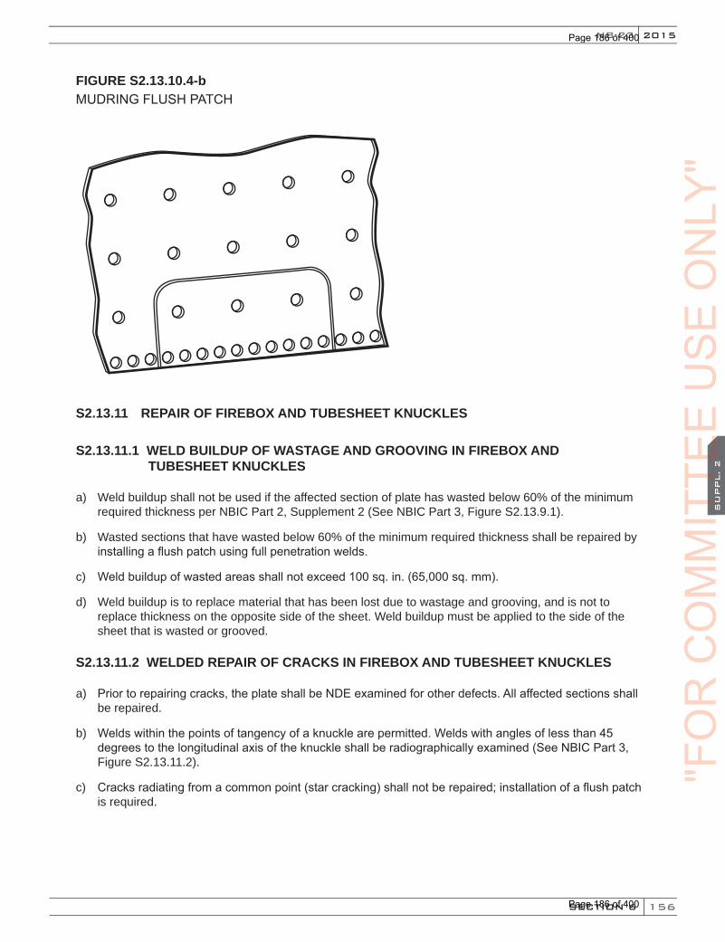
156
2015
SECTION 6
SU
PPL. 2
NB-23
FIGURE S2.13.10.4-bMUDRING FLUSH PATCH
S2.13.11 REPAIR OF FIREBOX AND TUBESHEET KNUCKLES
S2.13.11.1 WELD BUILDUP OF WASTAGE AND GROOVING IN FIREBOX AND TUBESHEET KNUCKLES
a) Weld buildup shall not be used if the affected section of plate has wasted below 60% of the minimum required thickness per NBIC Part 2, Supplement 2 (See NBIC Part 3, Figure S2.13.9.1).
b) Wasted sections that have wasted below 60% of the minimum required thickness shall be repaired by installing a flush patch using full penetration welds.
c) Weld buildup of wasted areas shall not exceed 100 sq. in. (65,000 sq. mm).
d) Weld buildup is to replace material that has been lost due to wastage and grooving, and is not to replace thickness on the opposite side of the sheet. Weld buildup must be applied to the side of the sheet that is wasted or grooved.
S2.13.11.2 WELDED REPAIR OF CRACKS IN FIREBOX AND TUBESHEET KNUCKLES
a) Prior to repairing cracks, the plate shall be NDE examined for other defects. All affected sections shall be repaired.
b) Welds within the points of tangency of a knuckle are permitted. Welds with angles of less than 45 degrees to the longitudinal axis of the knuckle shall be radiographically examined (See NBIC Part 3, Figure S2.13.11.2).
c) Cracks radiating from a common point (star cracking) shall not be repaired; installation of a flush patch is required.
"FO
RC
OM
MIT
TEE
CO
MM
ITTE
EC
OM
MIT
TEE
SU
PPL. 2
CO
MM
ITTE
ES
UPPL. 2
US
EO
NLY
"
Page 186 of 400
Page 186 of 400

157
NATIONAL BOARD INSPECTION CODE2015
SECTION 6
SU
PPL. 2
FIGURE S2.13.11.2KNUCKLE WELD ANGLES
Welds less than 45° to the longitudinal axis of the knuckle shall be radiographically examined
Welds less than 45° to the longitudinal axis of the knuckle shall be radiographically examined
45 degrees
45 degrees
90 degrees
45 degrees
45 degrees
90 degrees
S2.13.11.3 WELDED FLUSH PATCHES IN FIREBOX AND TUBESHEET KNUCKLES
Any patch not supported by means other than the weld, such as rivets, staybolts, tubes, or other forms of construction, shall have all weld seams radiographically examined. (See NBIC Part 3, Figure S2.13.11.3). All other requirements specified in NBIC Part 3, S2.13.9.3 shall be followed.
"FO
RC
OM
MIT
TEE
US
EO
NLY
"
Page 187 of 400
Page 187 of 400
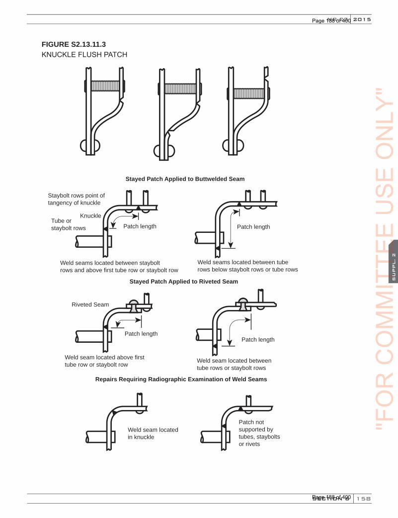
158
2015
SECTION 6
SU
PPL. 2
NB-23
FIGURE S2.13.11.3KNUCKLE FLUSH PATCH
Stayed Patch Applied to Buttwelded Seam
Stayed Patch Applied to Riveted Seam
Repairs Requiring Radiographic Examination of Weld Seams
Staybolt rows point oftangency of knuckle
KnuckleTube or staybolt rows
Riveted Seam
Patch length
Patch lengthPatch length
Patch length
Weld seams located between stayboltrows and above first tube row or staybolt row
Weld seams located between tuberows below staybolt rows or tube rows
Weld seam located above firsttube row or staybolt row
Weld seam located between tube rows or staybolt rows
Weld seam located in knuckle
Patch not supported by tubes, staybolts or rivets
"FO
RC
OM
MIT
TEE
CO
MM
ITTE
EC
OM
MIT
TEE
SU
PPL. 2
CO
MM
ITTE
ES
UPPL. 2
US
EO
NLY
"
Page 188 of 400
Page 188 of 400
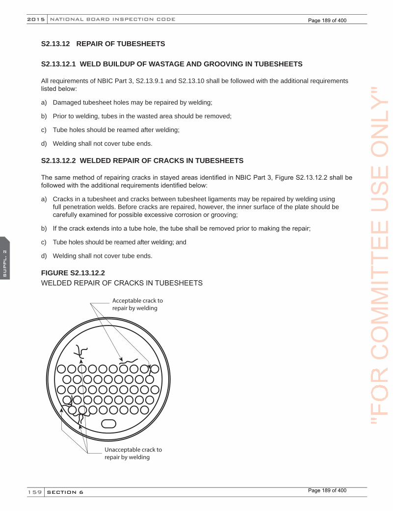
159
NATIONAL BOARD INSPECTION CODE2015
SECTION 6
SU
PPL. 2
S2.13.12 REPAIR OF TUBESHEETS
S2.13.12.1 WELD BUILDUP OF WASTAGE AND GROOVING IN TUBESHEETS
All requirements of NBIC Part 3, S2.13.9.1 and S2.13.10 shall be followed with the additional requirements listed below:
a) Damaged tubesheet holes may be repaired by welding;
b) Prior to welding, tubes in the wasted area should be removed;
c) Tube holes should be reamed after welding;
d) Welding shall not cover tube ends.
S2.13.12.2 WELDED REPAIR OF CRACKS IN TUBESHEETS
The same method of repairing cracks in stayed areas identified in NBIC Part 3, Figure S2.13.12.2 shall be followed with the additional requirements identified below:
a) Cracks in a tubesheet and cracks between tubesheet ligaments may be repaired by welding using full penetration welds. Before cracks are repaired, however, the inner surface of the plate should be carefully examined for possible excessive corrosion or grooving;
b) If the crack extends into a tube hole, the tube shall be removed prior to making the repair;
c) Tube holes should be reamed after welding; and
d) Welding shall not cover tube ends.
FIGURE S2.13.12.2WELDED REPAIR OF CRACKS IN TUBESHEETS
Acceptable crack to repair by welding
Unacceptable crack to repair by welding
Installation of �ush patch is required
"FO
RC
OM
MIT
TEE
US
EO
NLY
"
Page 189 of 400
Page 189 of 400

160
2015
SECTION 6
SU
PPL. 2
NB-23
S2.13.12.3 WELDED FLUSH PATCHES IN TUBESHEETS
a) The method of repair shall follow the same requirements identified in S2.13.10.3 with the following requirement as noted below:
1) Tubes, staybolts, and rivets should be installed after welding of the patch is completed. (See NBIC Part 3, Figure S2.13.12.3).
FIGURE S2.13.12.3TUBESHEET FLUSH PATCH
Flush patch weldedthrough tube holes and ligaments
Flush patch weldedaround tube holes
S2.13.13 SEAMS, JOINTS, AND RIVETS
S2.13.13.1 CAULKING RIVETED SEAMS AND RIVET HEADS
a) Caulking refers to the sealing of plate seams and rivet heads by driving the edge of one surface onto the other by use of a caulking tool.
b) The plate edges should be beveled to an angle not sharper than 70 degrees to the plane of the plate and as near thereto as practicable.
c) Caulking shall be done with a tool of such form that there is no danger of scoring or damaging the plate underneath the caulking edge, or splitting the caulked sheet.
"FO
RC
OM
MIT
TEE
CO
MM
ITTE
EC
OM
MIT
TEE
SU
PPL. 2
CO
MM
ITTE
ES
UPPL. 2
US
EO
NLY
"
Page 190 of 400
Page 190 of 400
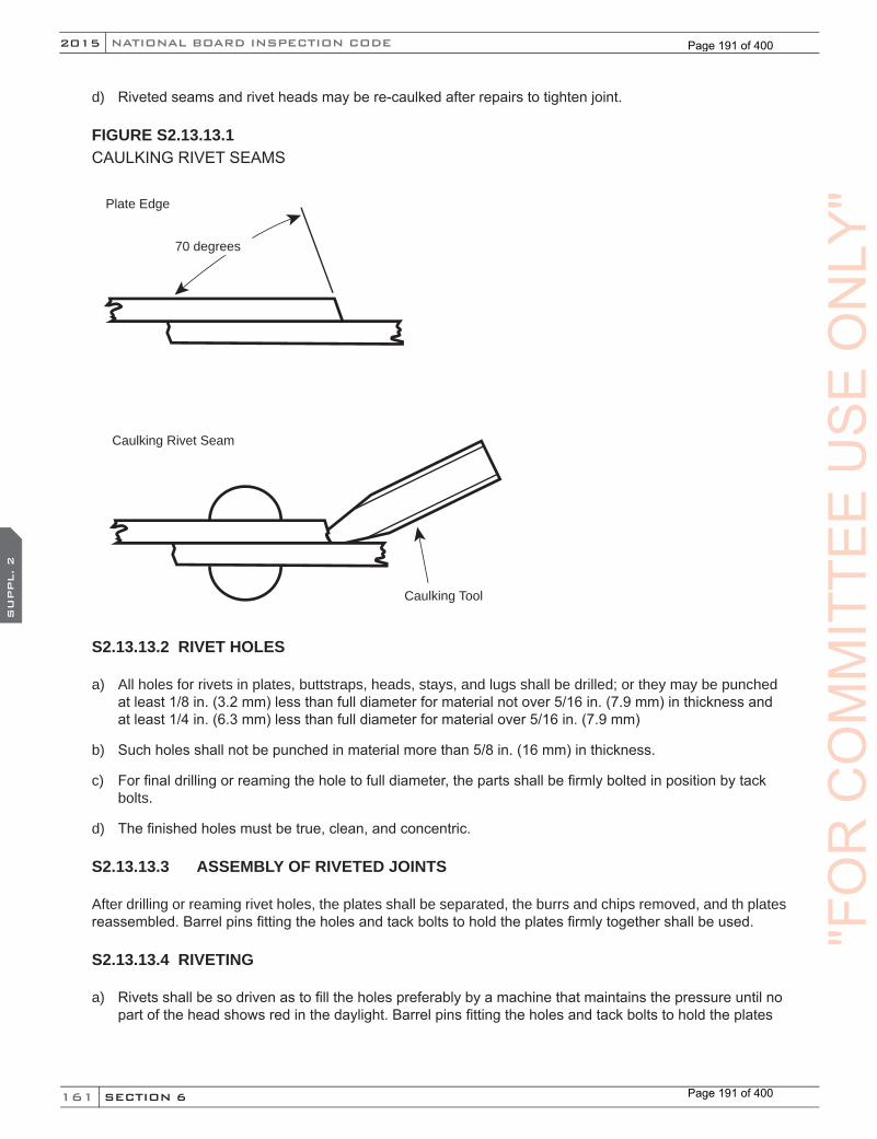
161
NATIONAL BOARD INSPECTION CODE2015
SECTION 6
SU
PPL. 2
d) Riveted seams and rivet heads may be re-caulked after repairs to tighten joint.
FIGURE S2.13.13.1 CAULKING RIVET SEAMS
Plate Edge
Caulking Tool
70 degrees
Caulking Rivet Seam
S2.13.13.2 RIVET HOLES
a) All holes for rivets in plates, buttstraps, heads, stays, and lugs shall be drilled; or they may be punched at least 1/8 in. (3.2 mm) less than full diameter for material not over 5/16 in. (7.9 mm) in thickness and at least 1/4 in. (6.3 mm) less than full diameter for material over 5/16 in. (7.9 mm)
b) Such holes shall not be punched in material more than 5/8 in. (16 mm) in thickness.
c) For final drilling or reaming the hole to full diameter, the parts shall be firmly bolted in position by tack bolts.
d) The finished holes must be true, clean, and concentric.
S2.13.13.3 ASSEMBLY OF RIVETED JOINTS
After drilling or reaming rivet holes, the plates shall be separated, the burrs and chips removed, and th plates reassembled. Barrel pins fitting the holes and tack bolts to hold the plates firmly together shall be used.
S2.13.13.4 RIVETING
a) Rivets shall be so driven as to fill the holes preferably by a machine that maintains the pressure until no part of the head shows red in the daylight. Barrel pins fitting the holes and tack bolts to hold the plates
"FO
RC
OM
MIT
TEE
US
EO
NLY
"
Page 191 of 400
Page 191 of 400
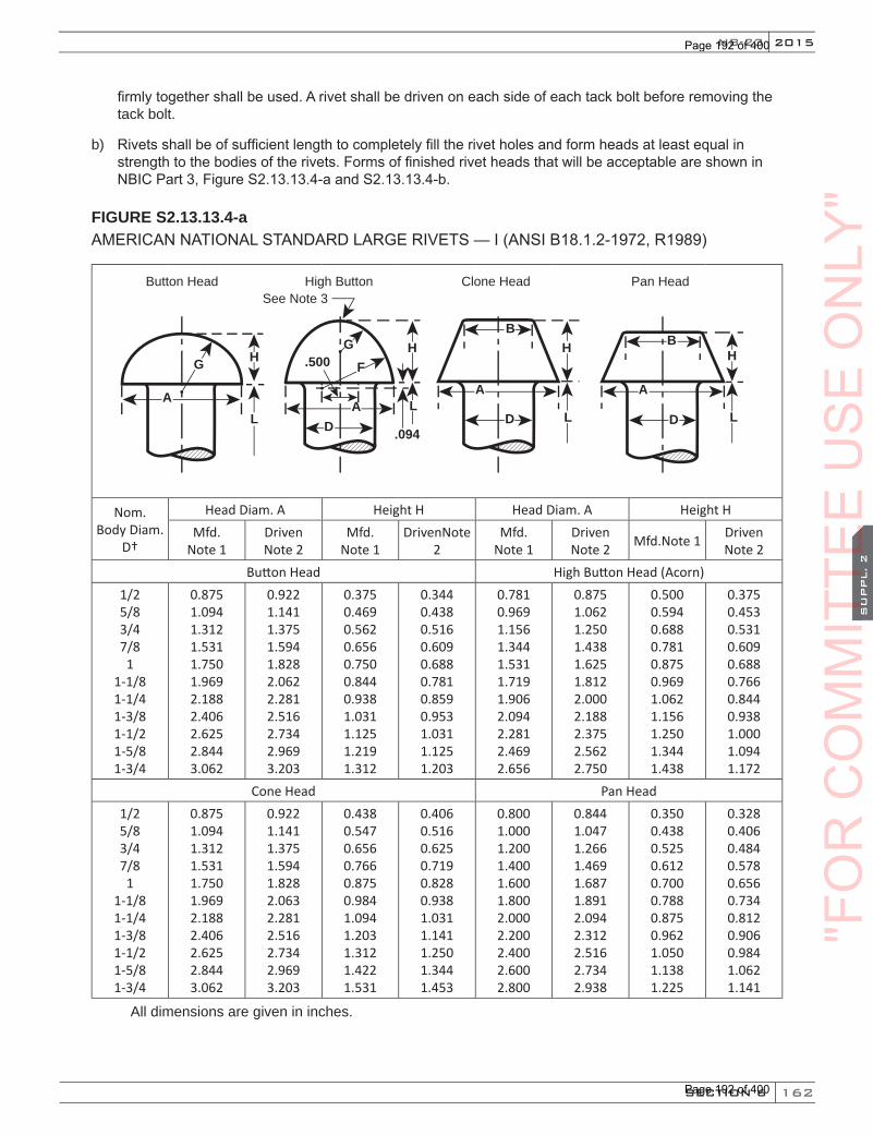
162
2015
SECTION 6
SU
PPL. 2
NB-23
firmly together shall be used. A rivet shall be driven on each side of each tack bolt before removing the tack bolt.
b) Rivets shall be of sufficient length to completely fill the rivet holes and form heads at least equal in strength to the bodies of the rivets. Forms of finished rivet heads that will be acceptable are shown in NBIC Part 3, Figure S2.13.13.4-a and S2.13.13.4-b.
FIGURE S2.13.13.4-aAMERICAN NATIONAL STANDARD LARGE RIVETS — I (ANSI B18.1.2-1972, R1989)
H
LA
AA A
D DL
L
H H
L
HF
GB
B.500
.094
See Note 3
D
G
Button Head High Button Clone Head Pan Head
Nom. Body Diam.
D†
Head Diam. A Height H Head Diam. A Height HMfd.
Note 1Driven Note 2
Mfd. Note 1
DrivenNote 2
Mfd. Note 1
Driven Note 2 Mfd.Note 1 Driven
Note 2Button Head High Button Head (Acorn)
1/2 5/8 3/4 7/8 1
1-1/8 1-1/4 1-3/8 1-1/2 1-5/8 1-3/4
0.875 1.094 1.312 1.531 1.750 1.969 2.188 2.406 2.625 2.844 3.062
0.922 1.141 1.375 1.594 1.828 2.062 2.281 2.516 2.734 2.969 3.203
0.375 0.469 0.562 0.656 0.750 0.844 0.938 1.031 1.125 1.219 1.312
0.344 0.438 0.516 0.609 0.688 0.781 0.859 0.953 1.031 1.125 1.203
0.781 0.969 1.156 1.344 1.531 1.719 1.906 2.094 2.281 2.469 2.656
0.875 1.062 1.250 1.438 1.625 1.812 2.000 2.188 2.375 2.562 2.750
0.500 0.594 0.688 0.781 0.875 0.969 1.062 1.156 1.250 1.344 1.438
0.375 0.453 0.531 0.609 0.688 0.766 0.844 0.938 1.000 1.094 1.172
Cone Head Pan Head1/2 5/8 3/4 7/8 1
1-1/8 1-1/4 1-3/8 1-1/2 1-5/8 1-3/4
0.875 1.094 1.312 1.531 1.750 1.969 2.188 2.406 2.625 2.844 3.062
0.922 1.141 1.375 1.594 1.828 2.063 2.281 2.516 2.734 2.969 3.203
0.438 0.547 0.656 0.766 0.875 0.984 1.094 1.203 1.312 1.422 1.531
0.406 0.516 0.625 0.719 0.828 0.938 1.031 1.141 1.250 1.344 1.453
0.800 1.000 1.200 1.400 1.600 1.800 2.000 2.200 2.400 2.600 2.800
0.844 1.047 1.266 1.469 1.687 1.891 2.094 2.312 2.516 2.734 2.938
0.350 0.438 0.525 0.612 0.700 0.788 0.875 0.962 1.050 1.138 1.225
0.328 0.406 0.484 0.578 0.656 0.734 0.812 0.906 0.984 1.062 1.141
All dimensions are given in inches.
"FO
RC
OM
MIT
TEE
CO
MM
ITTE
EC
OM
MIT
TEE
SU
PPL. 2
CO
MM
ITTE
ES
UPPL. 2
US
EO
NLY
"
Page 192 of 400
Page 192 of 400
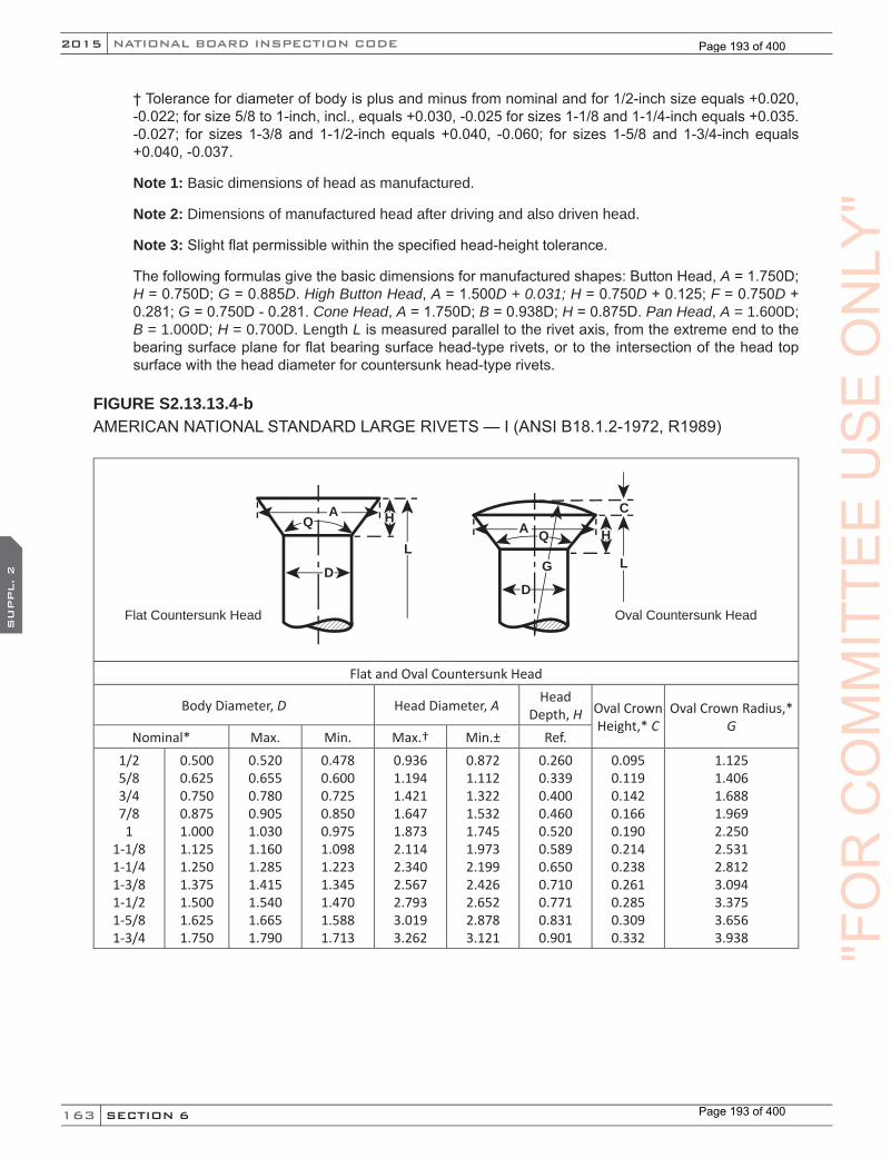
163
NATIONAL BOARD INSPECTION CODE2015
SECTION 6
SU
PPL. 2
† Tolerance for diameter of body is plus and minus from nominal and for 1/2-inch size equals +0.020, -0.022; for size 5/8 to 1-inch, incl., equals +0.030, -0.025 for sizes 1-1/8 and 1-1/4-inch equals +0.035. -0.027; for sizes 1-3/8 and 1-1/2-inch equals +0.040, -0.060; for sizes 1-5/8 and 1-3/4-inch equals +0.040, -0.037.
Note 1: Basic dimensions of head as manufactured.
Note 2: Dimensions of manufactured head after driving and also driven head.
Note 3: Slight flat permissible within the specified head-height tolerance.
The following formulas give the basic dimensions for manufactured shapes: Button Head, A = 1.750D; H = 0.750D; G = 0.885D. High Button Head, A = 1.500D + 0.031; H = 0.750D + 0.125; F = 0.750D + 0.281; G = 0.750D - 0.281. Cone Head, A = 1.750D; B = 0.938D; H = 0.875D. Pan Head, A = 1.600D; B = 1.000D; H = 0.700D. Length L is measured parallel to the rivet axis, from the extreme end to the bearing surface plane for flat bearing surface head-type rivets, or to the intersection of the head top surface with the head diameter for countersunk head-type rivets.
FIGURE S2.13.13.4-bAMERICAN NATIONAL STANDARD LARGE RIVETS — I (ANSI B18.1.2-1972, R1989)
A H
L
Q
D
A H
C
L
Q
G
D
Flat Countersunk Head Oval Countersunk Head
Flat and Oval Countersunk Head
Body Diameter, D Head Diameter, A Head Depth, H Oval Crown
Height,* COval Crown Radius,*
GNominal* Max. Min. Max.† Min.± Ref.
1/2 5/8 3/4 7/8 1
1-1/8 1-1/4 1-3/8 1-1/2 1-5/8 1-3/4
0.500 0.625 0.750 0.875 1.000 1.125 1.250 1.375 1.500 1.625 1.750
0.520 0.655 0.780 0.905 1.030 1.160 1.285 1.415 1.540 1.665 1.790
0.478 0.600 0.725 0.850 0.975 1.098 1.223 1.345 1.470 1.588 1.713
0.936 1.194 1.421 1.647 1.873 2.114 2.340 2.567 2.793 3.019 3.262
0.872 1.112 1.322 1.532 1.745 1.973 2.199 2.426 2.652 2.878 3.121
0.260 0.339 0.400 0.460 0.520 0.589 0.650 0.710 0.771 0.831 0.901
0.095 0.119 0.142 0.166 0.190 0.214 0.238 0.261 0.285 0.309 0.332
1.125 1.406 1.688 1.969 2.250 2.531 2.812 3.094 3.375 3.656 3.938 "F
OR
CO
MM
ITTE
EU
SE
ON
LY"
Page 193 of 400
Page 193 of 400

164
2015
SECTION 6
SU
PPL. 2
NB-23
E
D
K
L
Swell Neck
Swell Neck #
Body Diameter, D Diameter Under Head, ENeck Length, K*
Nominal* Max. Min. Max. (Basic) Min.1/2 5/8 3/4 7/8 1
1-1/8 1-1/4 1-3/8 1-1/2 1-5/8 1-3/4
0.500 0.625 0.750 0.875 1.000 1.125 1.250 1.375 1.500 1.625 1.750
0.520 0.655 0.780 0.905 1.030 1.160 1.285 1.415 1.540 1.665 1.790
0.478 0.600 0.725 0.850 0.975 1.098 1.223 1.345 1.470 1.588 1.713
0.563 0.688 0.813 0.938 1.063 1.188 1.313 1.438 1.563 1.688 1.813
0.543 0.658 0.783 0.908 1.033 1.153 1.278 1.398 1.523 1.648 1.773
0.250 0.312 0.375 0.438 0.500 0.562 0.625 0.688 0.750 0.812 0.875
All dimensions are given in inches. * Basic dimension as manufactured.
† Shard-edged head. ± Rounded or flat-edged irregularly shaped head (heads are not machined or trimmed.)
# The swell neck is applicable to all standard forms of large rivets except the flat countersunk and oval countersunk-head types.
The following formulas give the basic dimensions for manufactured shapes: Flat Countersunk Head, A= 1.810D; H = 1.192D (Max. A – D)/2; included angle Q of head = 78 degrees. Oval Countersunk Head,A = 1.810D; H = 1.192 (Max. A – D)/2; included angle of head = 78 degrees. Swell Neck, E = D + 0.063; K = 0.500D. Length L is measured parallel to the rivet axis, from the extreme end to the bearing surface plane for flat bearing surface head-type rivets, or to the intersection of the head top surface with the head diameter for countersunk head-type rivets.
Note: For more information see ANSI B18.1.2. A copy can be obtained in the machinist handbook.
S2.13.13.5 SEAL WELDING SEAM, JOINTS, AND RIVET HEADS
a) Prior to welding the area should be examined to assure that there are no cracks radiating from the rivet holes. (See NBIC Part 3, Figure S2.13.13.5).
b) Seal welding should not be performed if cracks are present in riveted areas.
c) Seal welding shall not be considered a strength weld.
"FO
RC
OM
MIT
TEE
CO
MM
ITTE
EC
OM
MIT
TEE
SU
PPL. 2
CO
MM
ITTE
ES
UPPL. 2
US
EO
NLY
"
Page 194 of 400
Page 194 of 400
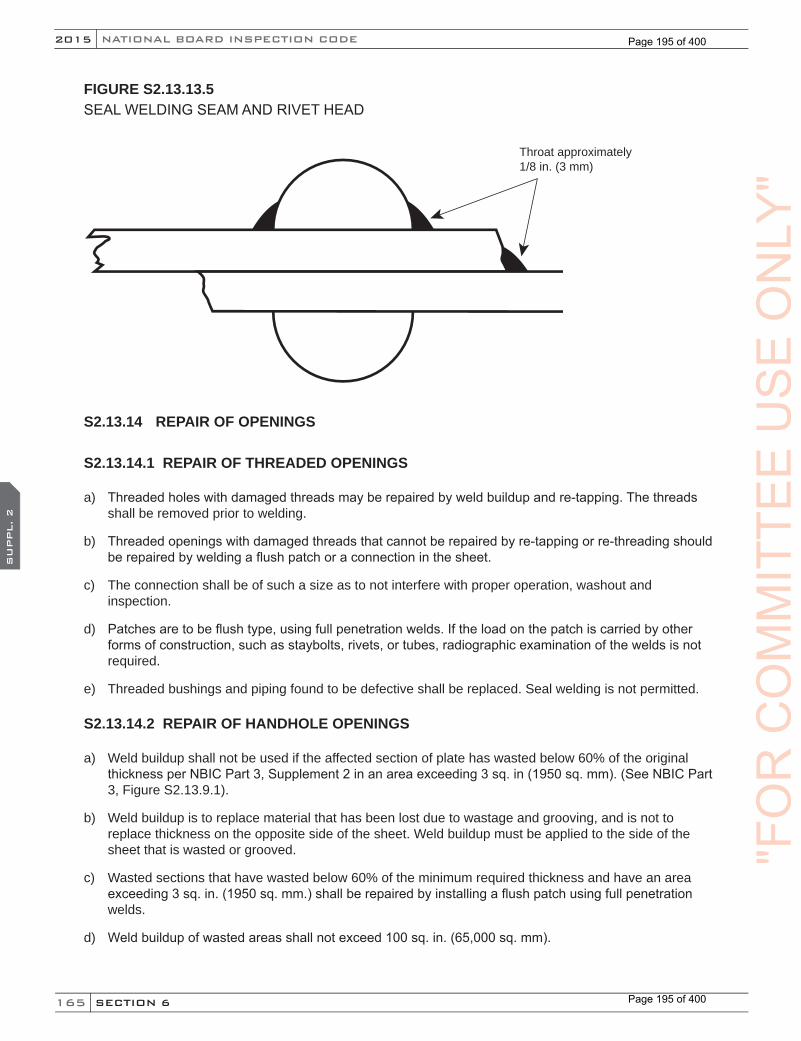
165
NATIONAL BOARD INSPECTION CODE2015
SECTION 6
SU
PPL. 2
FIGURE S2.13.13.5SEAL WELDING SEAM AND RIVET HEAD
Throat approximately1/8 in. (3 mm)
S2.13.14 REPAIR OF OPENINGS
S2.13.14.1 REPAIR OF THREADED OPENINGS
a) Threaded holes with damaged threads may be repaired by weld buildup and re-tapping. The threads shall be removed prior to welding.
b) Threaded openings with damaged threads that cannot be repaired by re-tapping or re-threading should be repaired by welding a flush patch or a connection in the sheet.
c) The connection shall be of such a size as to not interfere with proper operation, washout and inspection.
d) Patches are to be flush type, using full penetration welds. If the load on the patch is carried by other forms of construction, such as staybolts, rivets, or tubes, radiographic examination of the welds is not required.
e) Threaded bushings and piping found to be defective shall be replaced. Seal welding is not permitted.
S2.13.14.2 REPAIR OF HANDHOLE OPENINGS
a) Weld buildup shall not be used if the affected section of plate has wasted below 60% of the original thickness per NBIC Part 3, Supplement 2 in an area exceeding 3 sq. in (1950 sq. mm). (See NBIC Part 3, Figure S2.13.9.1).
b) Weld buildup is to replace material that has been lost due to wastage and grooving, and is not to replace thickness on the opposite side of the sheet. Weld buildup must be applied to the side of the sheet that is wasted or grooved.
c) Wasted sections that have wasted below 60% of the minimum required thickness and have an area exceeding 3 sq. in. (1950 sq. mm.) shall be repaired by installing a flush patch using full penetration welds.
d) Weld buildup of wasted areas shall not exceed 100 sq. in. (65,000 sq. mm).
"FO
RC
OM
MIT
TEE
US
EO
NLY
"
Page 195 of 400
Page 195 of 400
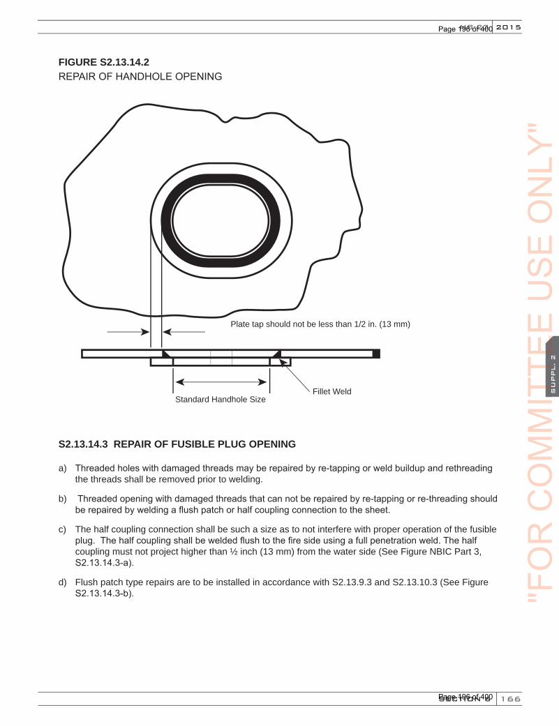
166
2015
SECTION 6
SU
PPL. 2
NB-23
FIGURE S2.13.14.2REPAIR OF HANDHOLE OPENING
Plate tap should not be less than 1/2 in. (13 mm)
Fillet WeldStandard Handhole Size
S2.13.14.3 REPAIR OF FUSIBLE PLUG OPENING
a) Threaded holes with damaged threads may be repaired by re-tapping or weld buildup and rethreading the threads shall be removed prior to welding.
b) Threaded opening with damaged threads that can not be repaired by re-tapping or re-threading should be repaired by welding a flush patch or half coupling connection to the sheet.
c) The half coupling connection shall be such a size as to not interfere with proper operation of the fusible plug. The half coupling shall be welded flush to the fire side using a full penetration weld. The half coupling must not project higher than ½ inch (13 mm) from the water side (See Figure NBIC Part 3, S2.13.14.3-a).
d) Flush patch type repairs are to be installed in accordance with S2.13.9.3 and S2.13.10.3 (See Figure S2.13.14.3-b). "F
OR
CO
MM
ITTE
EC
OM
MIT
TEE
CO
MM
ITTE
ES
UPPL. 2
CO
MM
ITTE
ES
UPPL. 2
US
EO
NLY
"
Page 196 of 400
Page 196 of 400
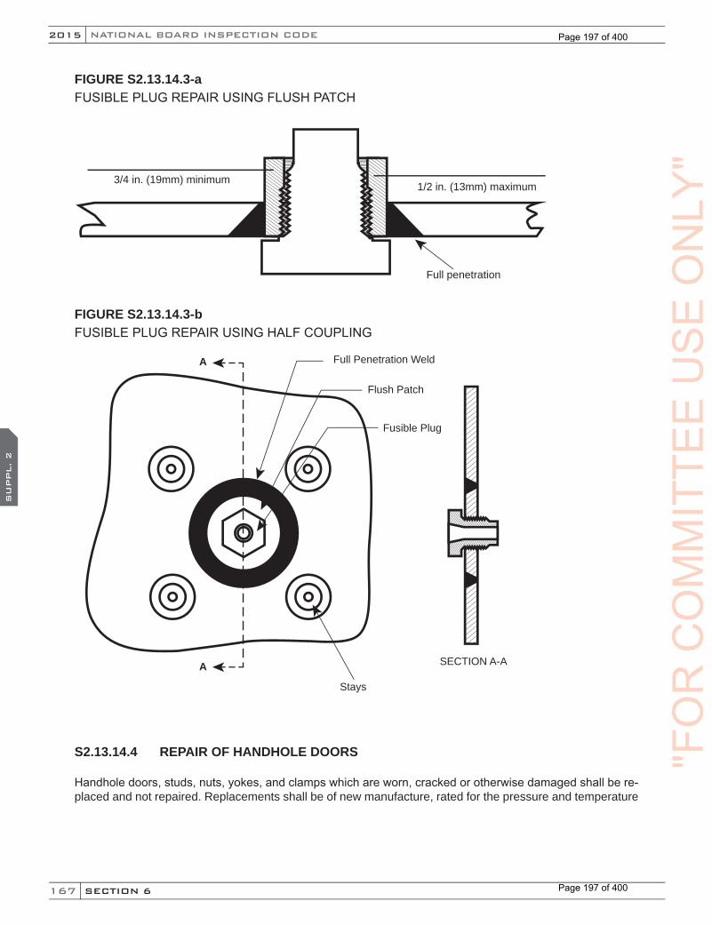
167
NATIONAL BOARD INSPECTION CODE2015
SECTION 6
SU
PPL. 2
FIGURE S2.13.14.3-aFUSIBLE PLUG REPAIR USING FLUSH PATCH
3/4 in. (19mm) minimum1/2 in. (13mm) maximum
Full penetration
FIGURE S2.13.14.3-bFUSIBLE PLUG REPAIR USING HALF COUPLING
A
A
Full Penetration Weld
Flush Patch
Fusible Plug
Stays
SECTION A-A
S2.13.14.4 REPAIR OF HANDHOLE DOORS
Handhole doors, studs, nuts, yokes, and clamps which are worn, cracked or otherwise damaged shall be re-placed and not repaired. Replacements shall be of new manufacture, rated for the pressure and temperature
"FO
RC
OM
MIT
TEE
US
EO
NLY
"
Page 197 of 400
Page 197 of 400

168
2015
SECTION 6
SU
PPL. 3
NB-23
SUPPLEMENT 3 REPAIR AND ALTERATION OF GRAPHITE PRESSURE EQUIPMENT
S3.1 SCOPE
Repairs to graphite pressure equipment require the use of certified impregnated graphite and cement. The determining factor in establishing the desired material properties is the resin impregnation cycle. If the resin impregnation cycle is not controlled, it is not possible to meet the minimum design values.
S3.2 REPAIRS
The requirements provided in this supplement shall apply, insofar as they are applicable to graphite pressure equipment. Graphite specific requirements include:
a) Organizations performing repairs shall be accredited as described in NBIC Part 3, 1.6 as appropriate for the scope of work to be performed.
b) When the standard governing the original construction is not the ASME Code, repairs or alterations shall conform to the edition of the original construction standard or specification most applicable to the work. Where the original code of construction is unknown, the edition and addenda of the ASME Code most appropriate for the work shall be used, provided the “R” Certificate Holder has the concurrence of the Inspector and the Jurisdiction where the pressure-retaining item is installed.
c) The materials used in making repairs or alterations shall conform to the requirements of the original code of construction except as provided in NBIC Part 3, S3.2 j). The “R” Certificate Holder is responsible for verifying identification of existing materials from original data, drawings, or unit records and identification of the materials to be installed.
d) When ASME is the original code of construction, replacement parts subject to internal or external pressure, which require shop inspection by an Authorized Inspector, shall be fabricated by an organization having an appropriate ASME Certificate of Authorization. The item shall be inspected and stamped as required by the applicable section of the ASME Code. A completed ASME Manufacturer’s Partial Data Report shall be supplied by the manufacturer. Further, all impregnated graphite material subject to internal or external pressure shall be fabricated by an organization having the appropriate ASME Certificate of Authorization. The impregnated graphite material shall be inspected and stamped as required by the applicable section of the ASME Code. A completed ASME Manufacturer’s Partial Data Report with supplementary U1B shall be supplied by the impregnated graphite material manufacturer.
e) When the original code of construction is other than ASME, replacement parts subject to internal or external pressure shall be manufactured by an organization certified as required by the original code of construction. The item shall be inspected and stamped as required by the original code of construction. Certification to the original code of construction as required by the original code of construction or equivalent shall be supplied with the item. When this is not possible or practicable, the organization fabricating the part may have a National Board Certificate of Authorization; replacement parts shall be documented on Form R-3 and the “R” Symbol Stamp applied as described in NBIC Part 3, Section 5.
f) Organizations performing repairs under an “R” stamp program shall register such repairs with the National Board.
g) Before signing the appropriate NBIC Form, the Inspector shall review the drawings, witness any required pressure test, ensure that the required nondestructive examinations have been performed satisfactorily, and that the other functions necessary to ensure compliance with the requirement of this code have been performed.
"FO
RC
OM
MIT
TEE
CO
MM
ITTE
EC
OM
MIT
TEE
SU
PPL. 3
CO
MM
ITTE
ES
UPPL. 3
US
EO
NLY
"
Page 198 of 400
Page 198 of 400

169
NATIONAL BOARD INSPECTION CODE2015
SECTION 6
SU
PPL. 3
h) Pressure-retaining items repaired in accordance with the NBIC shall be marked as required by NBIC Part 3, Section 5. The letter “G” shall be applied to the nameplate under the “R” stamp when graphite repairs are made. The alternate procedure defined in NBIC Part 3, 5.10 may be used in lieu of the stamping and nameplate attachment requirements of NBIC Part 3, Section 5.
i) Legible copies of the completed Form R-1, together with attachments, shall be distributed to the owner or user, the Inspector, the Jurisdiction if required, and the Authorized Inspection Agency responsible for inservice inspection. Form R-1 shall be registered with the National Board. Distribution of Form R-1 and attachments shall be the responsibility of the organization performing the repair.
j) Graphite parts that have previously been in service in one pressure vessel should not be used in a second vessel without prior approval of the owner. Consideration should be given to the service condition of the previous process and possible contamination of the subsequent process.
k) Blind cracks and delaminations may not be repaired by cement injection only.
l) Cracks and porosity in tubes may not be repaired. Cracked and porous sections may be removed so that the remainder of the tube may be used. Individual tube sections shall not be less than 24 in. (610 mm) in length, and the number of segments in a tube shall not exceed the quantity listed in NBIC Part 3, Table S3.2.
TABLE S3.2 PERMITTED QUANTITY OF TUBE SEGMENTS
Total Tube Length, ft. (m) Number of Tube Segments Number of Joints
6 (1.8) 1 09 (2.7) 2 1
12 (3.7) 3 214 (4.3) 3 216 (4.9) 4 318 (5.5) 4 320 (6.1) 4 322 (6.7) 4 324 (7.3) 5 427 (8.2) 5 4
m) Cementing procedure specifications shall be qualified by the repair organization. The specifications shall be qualified as required by the code of construction. Cementing procedure qualification shall be verified by the Inspector.
n) Cementing technicians shall be qualified by the repair organization. The technicians shall be qualified as required by the code of construction. A cementing technician is any individual who is responsible for proper joint preparation, cleaning parts to be joined, mixing cement, applying cement, securing the joint during the curing process, and controlling the curing process.
o) All records shall be made available to the Inspector.
p) Completed repairs shall be subjected to a pressure test. The test pressure shall not be less than the maximum allowable working pressure or twice the operating pressure, whichever is lower. The test pressure shall be maintained for 30 minutes.
"FO
RC
OM
MIT
TEE
US
EO
NLY
"
Page 199 of 400
Page 199 of 400
170
2015
SECTION 6
SU
PPL. 3
NB-23
q) Reimpregnation may be used to reduce porosity in an existing graphite component, which will improve the existing graphite component’s performance and expected life. Reimpregnation of graphite shall not be considered a means to restore original strength, nor shall it be considered a means to restore the original depth of impregnation.
S3.3 REPAIRS OF A ROUTINE NATURE
a) The following repairs shall be considered routine, and shall comply with NBIC Part 3, 3.3.2.
1) Machining — routine repair shall not include the machining of pressure-retaining parts with the exception of minor machining for cleaning and joint preparation not to exceed 1/32 in. (0.8 mm) of material thickness.
2) Repair of Gasket Surfaces — re-machining of gasket surfaces, re-serrating, or flattening is permitted if the design thickness is maintained.
3) Replacing Individual Tubes — drilling out and replacing tubes with new tubes or repaired tubes. Only certified materials shall be used for this repair.
4) Nozzle Replacement — replacement of nozzles by removing the old nozzle and cementing a new nozzle in place. This is applicable for nozzles with inside diameters not exceeding 18 in. (460 mm).
5) Plugging Tubes — plugging individual tubes using accepted procedures.
6) Surface Repair — surface repair by installation of plugs or inlay material shall not exceed 1 cu. in. (16 cu. cm) of total volume.
7) Replacement or Addition of Non-Load Bearing Attachments to Pressure-Retaining Item — For attachment of non-load bearing attachments to pressure-retaining items, the cementing procedure specification need only be qualified for the pressure part and cement to be used.
b) Complete records of these routine repairs shall be kept for review by the Inspector. The records shall include the number of tubes replaced or plugged and their location within the tube bundle.
S3.4 ALTERATIONS
a) The requirements provided in this section shall apply, insofar as they are applicable to the materials discussed herein. Completed alterations shall be subjected to a pressure test not less than that required by the code of construction. The test pressure shall be maintained for a minimum of 30 minutes. The pressure shall be reduced to MAWP and maintained for inspection.
b) The nameplate shall be applied in accordance with Section 5 of this part. The letter “G” shall be applied to the nameplate under the “R” stamp when graphite alterations are made. The alternate procedure defined in 5.10 may be used in lieu of the stamping and nameplate attachment requirements of NBIC Part 3, Section 5 .
c) Organizations performing alterations under an “R” stamp program shall register such alterations with the National Board.
S3.5 REPAIR GUIDE FOR IMPERVIOUS GRAPHITE
S3.5.1 INTRODUCTION
a) This section is intended to provide suggested process and technique details for repairs. This section should be used as a guide by the repair organization in developing specific repair procedures.
"FO
RC
OM
MIT
TEE
CO
MM
ITTE
EC
OM
MIT
TEE
SU
PPL. 3
CO
MM
ITTE
ES
UPPL. 3
US
EO
NLY
"
Page 200 of 400
Page 200 of 400

171
NATIONAL BOARD INSPECTION CODE2015
SECTION 6
SU
PPL. 3
b) Damage to domes (heads), tubesheets, or nozzles is invariably a sign of improper installation, operation, or maintenance. Because such damage is random in nature, each case must be analyzed separately to determine the appropriate repair procedure, and the economics of repair versus replacement.
c) Impervious graphite is a machinable material. Parts can be modified or repaired in the field, or in a repair shop.
d) Machining operations may be handled with high-speed steel tools. Extensive machining requires tungsten carbide or diamond tooling. No cooling or flushing fluid is required, nor should either be used.
e) Cleanliness is important. Dusty, dirty, and chemically contaminated surfaces prevent proper cement adhesion. Poor cement adhesion will result in a low strength joint or a joint which leaks. All surfaces should be neutralized to a pH of 7. Graphite parts should be cleaned and washed with acetone to remove all moisture.
f) All damage should be examined and evaluated to determine the cause. Identification and elimination of the cause is essential in helping to prevent a recurrence.
g) A hydrophilic solvent wash on the surface of the damaged part is useful in identifying the full extent of the cracks. The hydrophilic solvent will quickly evaporate from the surface, leaving the cracks damp and clearly visible.
FIGURE S3.5.1-aTYPICAL TUBE-TUBESHEET JOINTS
"FO
RC
OM
MIT
TEE
US
EO
NLY
"
Page 201 of 400
Page 201 of 400
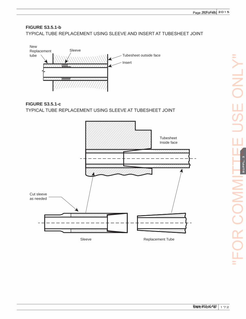
172
2015
SECTION 6
SU
PPL. 3
NB-23
FIGURE S3.5.1-bTYPICAL TUBE REPLACEMENT USING SLEEVE AND INSERT AT TUBESHEET JOINT
Tubesheet outside face
Insert
SleeveNewReplacementtube
FIGURE S3.5.1-cTYPICAL TUBE REPLACEMENT USING SLEEVE AT TUBESHEET JOINT
Tubesheet Inside face
Cut sleeve as needed
Sleeve Replacement Tube"F
OR
CO
MM
ITTE
EC
OM
MIT
TEE
CO
MM
ITTE
ES
UPPL. 3
CO
MM
ITTE
ES
UPPL. 3
US
EO
NLY
"
Page 202 of 400
Page 202 of 400
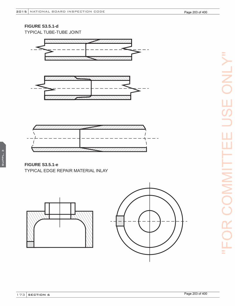
173
NATIONAL BOARD INSPECTION CODE2015
SECTION 6
SU
PPL. 3
FIGURE S3.5.1-dTYPICAL TUBE-TUBE JOINT
FIGURE S3.5.1-eTYPICAL EDGE REPAIR MATERIAL INLAY
"FO
RC
OM
MIT
TEE
US
EO
NLY
"
Page 203 of 400
Page 203 of 400
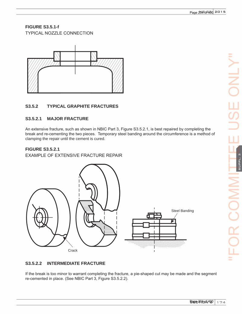
174
2015
SECTION 6
SU
PPL. 3
NB-23
FIGURE S3.5.1-fTYPICAL NOZZLE CONNECTION
S3.5.2 TYPICAL GRAPHITE FRACTURES
S3.5.2.1 MAJOR FRACTURE
An extensive fracture, such as shown in NBIC Part 3, Figure S3.5.2.1, is best repaired by completing the break and re-cementing the two pieces. Temporary steel banding around the circumference is a method of clamping the repair until the cement is cured.
FIGURE S3.5.2.1EXAMPLE OF EXTENSIVE FRACTURE REPAIR
Crack
Steel Banding
S3.5.2.2 INTERMEDIATE FRACTURE
If the break is too minor to warrant completing the fracture, a pie-shaped cut may be made and the segment re-cemented in place. (See NBIC Part 3, Figure S3.5.2.2).
"FO
RC
OM
MIT
TEE
CO
MM
ITTE
EC
OM
MIT
TEE
SU
PPL. 3
CO
MM
ITTE
ES
UPPL. 3
US
EO
NLY
"
Page 204 of 400
Page 204 of 400
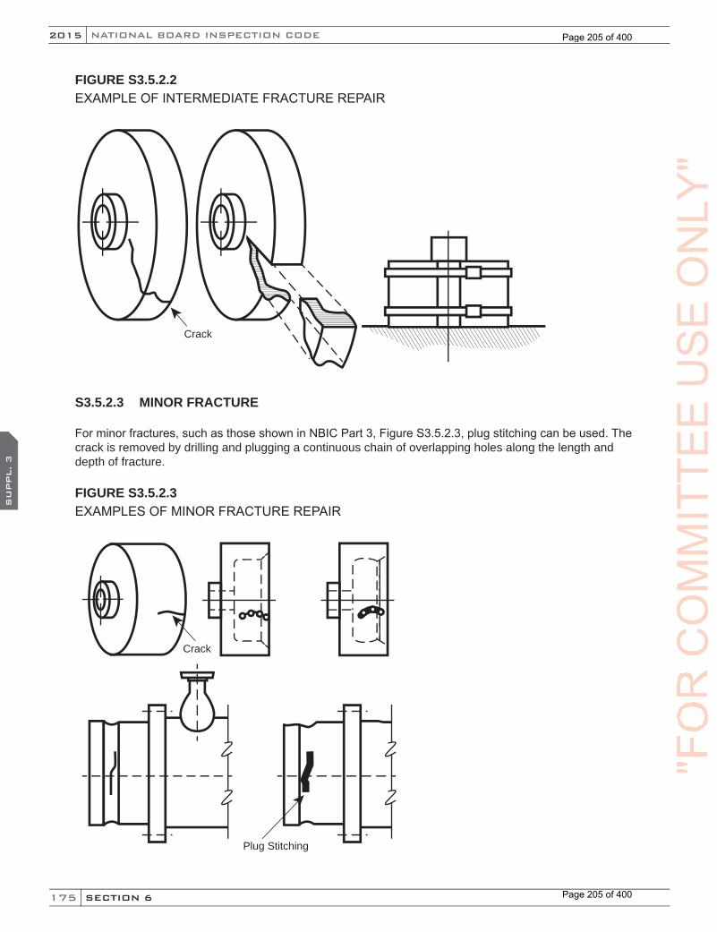
175
NATIONAL BOARD INSPECTION CODE2015
SECTION 6
SU
PPL. 3
FIGURE S3.5.2.2EXAMPLE OF INTERMEDIATE FRACTURE REPAIR
Crack
S3.5.2.3 MINOR FRACTURE
For minor fractures, such as those shown in NBIC Part 3, Figure S3.5.2.3, plug stitching can be used. The crack is removed by drilling and plugging a continuous chain of overlapping holes along the length and depth of fracture.
FIGURE S3.5.2.3EXAMPLES OF MINOR FRACTURE REPAIR
Crack
Plug Stitching
"FO
RC
OM
MIT
TEE
US
EO
NLY
"
Page 205 of 400
Page 205 of 400
176
2015
SECTION 6
SU
PPL. 3
NB-23
S3.5.2.4 FINISHING THE REPAIRa) The parts should be held in place to prevent movement while curing the cemented joint to achieve a
proper repair. The repair firm should take care to ensure that the cement joint thickness is within the range recommended by the cement manufacturer. Care spent in precisely aligning the parts while clamping will avoid many finishing and machining operations later. Particular attention should be given to gasket and other bearing surfaces.
b) Gasket and bearing surfaces may have to be machined, filed, or sanded before the job is completed.Gasket serrations must be clean and continuous. Serrations can be easily re-cut into graphite and any repair plugs that cross the gasket surface.
S3.5.3 GRAPHITE REPAIR BY PLUG STITCHING
a) Plug stitching is a form of repair by material inlaying. In this case, the inlays are small cylindrical impervious graphite plugs. The crack or fracture is removed by drilling and plugging a continuous series of overlapping holes along its length and depth.
b) Most plug stitching is done with 7/8 in. (22 mm) diameter plugs. The plugs are laid out along the fracture line on a pitch of 5/8 in. (16 mm) centers. The overlap of plug material is 1/4 in. (6 mm) along the fracture line. A number of plug sizes are available and are used in repair, and the amount of overlapping is proportional to their diameters.
(15)
"FO
RC
OM
MIT
TEE
CO
MM
ITTE
EC
OM
MIT
TEE
SU
PPL. 3
CO
MM
ITTE
ES
UPPL. 3
US
EO
NLY
"
Page 206 of 400
Page 206 of 400
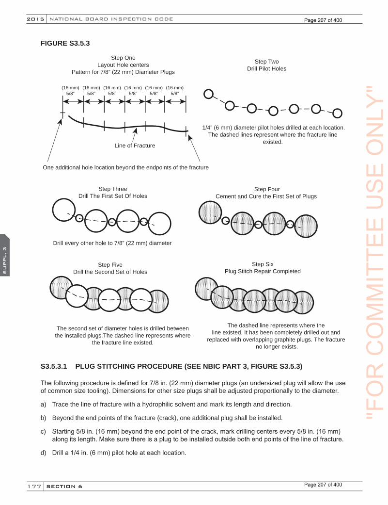
177
NATIONAL BOARD INSPECTION CODE2015
SECTION 6
SU
PPL. 3
FIGURE S3.5.3
Line of Fracture
Step OneLayout Hole centers
Pattern for 7/8” (22 mm) Diameter Plugs
Step TwoDrill Pilot Holes
(16 mm)5/8”
(16 mm)5/8”
(16 mm)5/8”
(16 mm)5/8”
(16 mm)5/8”
(16 mm)5/8”
One additional hole location beyond the endpoints of the fracture
1/4” (6 mm) diameter pilot holes drilled at each location.The dashed lines represent where the fracture line
existed.
Step ThreeDrill The First Set Of Holes
Drill every other hole to 7/8” (22 mm) diameter
Step FourCement and Cure the First Set of Plugs
Step FiveDrill the Second Set of Holes
The second set of diameter holes is drilled between the installed plugs.The dashed line represents where
the fracture line existed.
Step SixPlug Stitch Repair Completed
The dashed line represents where the line existed. It has been completely drilled out and
replaced with overlapping graphite plugs. The fracture no longer exists.
S3.5.3.1 PLUG STITCHING PROCEDURE (SEE NBIC PART 3, FIGURE S3.5.3)
The following procedure is defined for 7/8 in. (22 mm) diameter plugs (an undersized plug will allow the use of common size tooling). Dimensions for other size plugs shall be adjusted proportionally to the diameter.
a) Trace the line of fracture with a hydrophilic solvent and mark its length and direction.
b) Beyond the end points of the fracture (crack), one additional plug shall be installed.
c) Starting 5/8 in. (16 mm) beyond the end point of the crack, mark drilling centers every 5/8 in. (16 mm) along its length. Make sure there is a plug to be installed outside both end points of the line of fracture.
d) Drill a 1/4 in. (6 mm) pilot hole at each location.
"FO
RC
OM
MIT
TEE
US
EO
NLY
"
Page 207 of 400
Page 207 of 400

178
2015
SECTION 6
SU
PPL. 3
NB-23
e) Redrill a 7/8 in. (22 mm) hole at every other pilot hole. Holes must be drilled the full depth of the crack. The depth and direction of the crack can be checked with hydrophilic solvent.
f) A 7/8 in. (22 mm) diameter reamer may be used to true the drilled holes.
g) Dry fit a plug into the holes. There should be 0.005 in. to 0.010 in. (0.13 mm to 0.25 mm) clearance for the cement joint. At no time should there be a force fit of plugs into any drilled hole. Provisions shall be provided for venting trapped air.
h) Sand the outside surface of the plugs. Thoroughly clean all the surfaces of the repair, plugs, and drilled holes with hydrophilic solvent.
i) Apply graphite cement to both plugs and holes. All surfaces of plugs and holes to be joined are to be wetted with cement.
j) Insert the cemented plugs into the holes allowing 1/16 in. (1.5 mm) of the plug to extend beyond the surface of the graphite part.
k) Cure the graphite cement according to the cement manufacturer’s instruction.
l) At this point, half of the plug stitch repair is completed. A row of plugs has been installed with 1/4 in. (6 mm) pilot holes between them.
m) Redrill the remaining pilot holes to 7/8 in. (22 mm) diameter. The drill will remove part of the plugs that were installed. It is important to have the plugs replace all of the fracture. If the new holes do not cut into the installed plugs, it will be necessary to repeat the procedure between these holes and plug locations to ensure that all of the crack has been repaired. The line of fracture is completely removed by the overlapping effect of the graphite plugs.
n) After the second set of holes have been drilled, repeat the plug cementing procedures.
o) Contour the plugs to provide a smooth transition into the adjoining surface area. The finished repair may be coated with a wash coat for appearance.
S3.5.3.2 FIGURES — TYPICAL PLUG STITCHING PROCEDURE
a) Step one: Layout hole centers.
b) Step two: Drilling pilot holes.
c) Step three: Drilling the first set of holes.
d) Step four: Cementing and curing the first set of plugs.
e) Step five: Drilling the second set of holes.
f) Step six: Plug stitching repair completed.
S3.5.4 REIMPREGNATION OF GRAPHITE PARTS (TUBESHEETS, HEADS, ANDBLOCKS)
a) As a function of time, temperature, and chemical exposure, the resin used to impregnate graphite may shrink and/or degrade. As such, it is possible for voids to develop in impregnated graphite that has been in chemical service for a period of time. The resin loss can vary from slight to almost complete loss of impregnation. There is no practical way to determine the amount of resin remaining in the pores. However, a pressure test will determine if the graphite has continuous porosity.
"FO
RC
OM
MIT
TEE
CO
MM
ITTE
EC
OM
MIT
TEE
SU
PPL. 3
CO
MM
ITTE
ES
UPPL. 3
US
EO
NLY
"
Page 208 of 400
Page 208 of 400

179
NATIONAL BOARD INSPECTION CODE2015
SECTION 6
SU
PPL. 3
b) Reimpregnation of a graphite component may be used to reduce porosity in an existing graphite component, which in turn will improve the performance and expected life of the existing graphite components. A written re-impregnation procedure acceptable to the Inspector is required. The reimpregnation procedure shall include as a minimum:
1) Decontamination and drying of the graphite component
2) Subjecting the component to a vacuum
3) Introducing resin under pressure
4) Curing the resin at a specified temperature and time
5) Leak test
S3.5.4.1 CONTROL OF IMPREGNATION MATERIAL
a) Impregnation material shall be the same as that specified in the Reimpregnation Procedure. Each impregnation material shall be traceable by the name of its manufacturer and the trade name or number of that manufacturer.
b) The impregnation material manufacturer shall supply the Certificate Holder a Certificate of Analysis for each material. It shall include the following:
1) Impregnation material identification
2) Batch number(s)
3) Date of manufacture
4) Shelf life
5) Viscosity per ASTM D 2393
6) Specific gravity
c) Prior to reimpregnation, and at subsequent intervals not to exceed 14 days, the Certificate Holder shall test each batch of impregnation material to assure that the characteristics of the material have not changed from values specified in the Reimpregnation Procedure. The values obtained for viscosity and specific gravity for the impregnation material shall be within the limits specified by the manufacturer and as listed in the Reimpregnation Procedure. The test values shall be made available to the Inspector.
S3.5.4.2 FINISHING THE REPAIR
a) The parts should be held in place to prevent movement while curing the cemented joint to achieve a proper repair. The repair firm should take care to ensure that the cement joint thickness is within the range recommended by the cement manufacturer. Care spent in precisely aligning the parts while clamping will avoid many finishing and machining operations later. Particular attention should be given to gasket and other bearing surfaces.
b) Gasket and bearing surfaces may have to be machined, filed, or sanded before the job is completed. Gasket serrations must be clean and continuous. Serrations can be easily re-cut into graphite and any repair plugs that cross the gasket surface.
"FO
RC
OM
MIT
TEE
US
EO
NLY
"
Page 209 of 400
Page 209 of 400
180
2015
SECTION 6
SU
PPL. 3
NB-23
S3.5.5 PLUGGING OF LEAKING OR DAMAGED TUBES
a) The material used for plugging tubes shall comply with the requirements of the ASME Boiler and Pressure Vessel Code, Section VIII, Division 1, Part UIG.
b) The point(s) of leakage shall be verified, and the corresponding leak site(s) shall be marked/labeled on the tubesheet, and recorded.
c) A minimum of two (2) graphite plugs, each with a minimum length of 1 in. (25 mm), shall be used to plug each end of the tube(s) in question. This represents a minimum total of four (4) plugs per tube.
d) The tube(s) shall be prepared for plugging by enlarging the inside of the tube(s) with a suitable drill bit or reamer.
1) To ensure a sound cement joint between the tube sidewall and the plug, a slightly smaller diameter plug shall be selected. The maximum clearance between the tube inside diameter and the outside diameter of the plug shall not exceed 3/32 in. (2.4 mm).
2) As an alternative to d)1) a mandrel with an abrasive, such as sandpaper, may be used, as long as the maximum tube I.D. to plug O.D. clearance of 3/32 in. (2.4 mm) is not exceeded.
3) The minimum plug insertion depth of the prepared hole(s) shall meet the minimum combined plug length requirements of “c”. When the minimum plug length of “c” is exceeded, the total insertion depth of the plugs may exceed the combined length of the plugs; however, the longer plugs shall not project outside the face of the tube(s) being plugged.
e) Plugging of leaking or damaged tubes shall be performed by certified cementing technicians, using qualified cementing procedures, in accordance with the requirements of the ASME Boiler and Pressure Vessel Code, Section VIII, Division 1, Part UIG.
f) The cement shall be prepared per the cement manufacturer’s instructions.
g) When cementing the plugs, 100% of individual plugs, as well as the inside diameter of the tube opening(s), shall be coated with cement. The plugs shall then be inserted one by one, against each other, into each end of the tube(s) being plugged.
h) Once the plugging is completed, and before the cement cures, the endplugs may need to be held in place, as newly cemented plugs may exhibit a tendency to dislodge from the plugged tube(s) prior to final curing of the cement.
i) Curing time is dependent upon the cement manufacturer’s instructions, and is considered complete when the cement is hardened to the point that it cannot be indented with pressure from a flat screwdriver or other similar instrument.
j) After the cement is completely cured, the plugged, cemented area(s) on the tubesheet face may be dressed with sandpaper or other suitable abrasive.
k) Repaired tubes shall be tested in accordance with this code, using a method acceptable to the Inspector, with a written procedure as approved by the manufacturer’s internal quality system, to ensure leaks have been repaired.
l) The scope of the work completed shall be described and reported on a Form R-1.
S3.5.6 TUBE REPLACEMENT
Tube replacement should be performed with the unit preferably in the horizontal position. Avoid replacing adjacent tubes simultaneously because the replacement areas may overlap or reduce the ligament between
(15)
"FO
RC
OM
MIT
TEE
CO
MM
ITTE
EC
OM
MIT
TEE
SU
PPL. 3
CO
MM
ITTE
ES
UPPL. 3
US
EO
NLY
"
Page 210 of 400
Page 210 of 400
181
NATIONAL BOARD INSPECTION CODE2015
SECTION 6
SU
PPL. 3
holes and possibly damage the tubesheet. The general steps used in horizontal tube replacement follow below.
a) The material used for tube replacement shall comply with the requirements of the ASME Boiler and Pressure Vessel Code, Section VIII, Division 1, Part UIG.
b) Tube replacement shall be performed by qualified cementing technicians, using qualified cementing procedures, in accordance with the requirements of the ASME Boiler and Pressure Vessel Code, Section VIII, Division 1, Part UIG-79(b), (e), and UIG-80(b).
c) Determine the thickness of each tubesheet and inside distance between the tubesheets to obtain tube and sleeve length.
d) Access each tubesheet face, clearly identify and mark each tube hole on each tubesheet of the tubes to be replaced.
e) Prepare/clean the existing tube hole in preparation for extracting the damaged tube. Some holes may contain plugs which require removal. A boring tool slightly larger than the outside diameter of the tube being replaced is required.
f) Drill/bore out the tube hole in each tubesheet to release the tube from the tubesheet. Exercise caution when centering and align cutting to the common axis of the tube.
g) The damaged tube should disengage and become loose. Using guides, remove the damaged tube. Ensure that no debris is trapped in the space where the tube was removed (Fig. S3.5.6-a).
h) Replacement tube shall have sleeves at the ends cemented in the bored holes to replace the material in the tubesheet that was bored out to access the damaged tube (Fig. S3.5.6-b and S3.5.6-c).
1) Dry-fit a new tube and sleeve.
2) The sleeve length may vary.
3) Prior to applying cement, prepare and clean all surfaces to be cemented.
i) Cement the ID of the prepared bore in the floating tubesheet and the tube end OD at the fixed tubesheet. (Fig. S3.5.6-b).
j) Insert the tube through the fixed tubesheet and through the floating tubesheet cemented bore so that it protrudes. Cement the ID of the fixed tubesheet bore as shown in (Fig. S3.5.6-c). The use of alignment dowels can assist/guide in tube handling.
k) Cement the OD of the tube end protruding from the floating tubesheet. Cement the ID of the mating sleeve end, fit it to the cemented tube end and push the assembly part-way into the floating tubesheet. Cement the remainder of the OD of the floating tube end sleeve. Push this cemented assembly the rest of the way into the floating tubesheet (Fig S3.5.6-c).
l) Cement the ID and OD of the sleeve for the fixed tubesheet and insert it until it mates with the tube end inside. Push together cemented tube/sleeve assemblies. (Fig S3.5.6-d). Clean/wipe away any excess cement.
m) Apply slight pressure on the sleeves to seat the joints. Remove excess cement.
n) Maintain pressure and cure both ends of the cemented assembly according to the cement manufacturer’s instructions.
o) Sleeves may be trimmed after curing.
"FO
RC
OM
MIT
TEE
US
EO
NLY
"
Page 211 of 400
Page 211 of 400
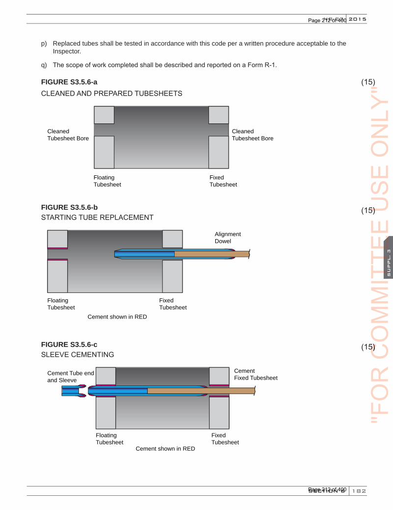
182
2015
SECTION 6
SU
PPL. 3
NB-23
p) Replaced tubes shall be tested in accordance with this code per a written procedure acceptable to the Inspector.
q) The scope of work completed shall be described and reported on a Form R-1.
FIGURE S3.5.6-a CLEANED AND PREPARED TUBESHEETS
CleanedTubesheet Bore
CleanedTubesheet Bore
FixedTubesheet
FloatingTubesheet
FIGURE S3.5.6-b STARTING TUBE REPLACEMENT
Cement shown in RED
AlignmentDowel
FixedTubesheet
FloatingTubesheet
FIGURE S3.5.6-c SLEEVE CEMENTING
Cement shown in RED
CementFixed Tubesheet
Cement Tube endand Sleeve
FixedTubesheet
FloatingTubesheet
(15)
(15)
(15)
"FO
RC
OM
MIT
TEE
CO
MM
ITTE
EC
OM
MIT
TEE
SU
PPL. 3
CO
MM
ITTE
ES
UPPL. 3
(15) CO
MM
ITTE
E(15)
US
E
(15) US
E
(15)
ON
LY"
Page 212 of 400
Page 212 of 400
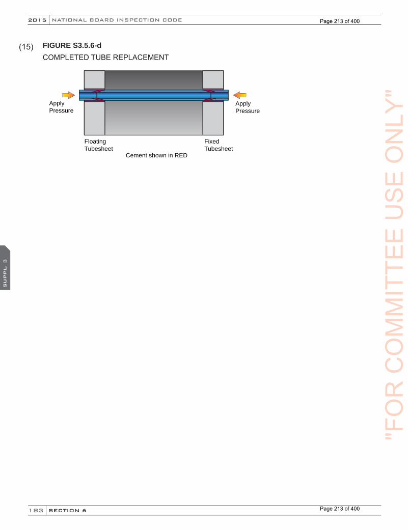
183
NATIONAL BOARD INSPECTION CODE2015
SECTION 6
SU
PPL. 3
FIGURE S3.5.6-d COMPLETED TUBE REPLACEMENT
Cement shown in RED
ApplyPressure
ApplyPressure
FixedTubesheet
FloatingTubesheet
(15)
"FO
RC
OM
MIT
TEE
US
EO
NLY
"
Page 213 of 400
Page 213 of 400

184
2015
SECTION 6
SU
PPL. 4
NB-23
SUPPLEMENT 4 REPAIR AND ALTERATION OF FIBER-REINFORCED THERMOSETTING PLASTIC PRESSURE EQUIPMENT
S4.1 SCOPE
a) This supplement provides general requirements that apply to repairs and alterations to fiber-reinforced pressure-retaining items.
b) The letters “RP” shall be included on the “R” Certificate of Authorization for those organizations authorized to perform repairs/alterations of fiber-reinforced plastic pressure equipment.
S4.2 INSPECTOR QUALIFICATIONS
The “R” Stamp Holder’s inspector shall have the following qualifications:
a) No fewer than five years of current verifiable documented experience in an occupational function that has a direct relationship to Reinforced Thermoplastic (RTP) fabrication and inspection, following customer or national standards, and be directly involved in the following activities:
1) the development of plans, drawings, procedures, inspection requirements, acceptance criteria, and personnel qualification requirements;
2) fabrication, construction, and supervision of personnel in the production of assemblies or subassemblies;
3) detection and measurement of nonconformities by application of visual or other nondestructive evaluation processes to written procedures;
4) supervision of personnel engaged in material and component examination;
5) repairs of equipment or supervision of personnel performing repairs;
6) preparation of written procedures for assembly, acceptance, nondestructive evaluation, or destructive tests;
7) qualification of secondary bonders, laminators, and welders to applicable codes, standards, or specifications;
8) operation techniques or activities used to fulfill quality control requirements for RTP fabrication or assembly; and
9) train the occupational skills of fabrication or assembly of RTP equipment.
b) The Inspector shall meet the following visual and educational requirements:
1) be able to read a Jaeger Type No. 1 standard chart at a distance of not less than 12 in. (305 mm);
2) be capable of distinguishing and differentiating contrast between colors;
3) have visual acuity checked annually to assure natural or corrected near distance vision; and
4) be a high school graduate or hold a state or military approved high school equivalency diploma.
c) The employer of the inspector shall certify that the employee complies with the above qualification requirements.
"FO
RC
OM
MIT
TEE
CO
MM
ITTE
EC
OM
MIT
TEE
SU
PPL. 4
CO
MM
ITTE
ES
UPPL. 4
US
EO
NLY
"
Page 214 of 400
Page 214 of 400
185
NATIONAL BOARD INSPECTION CODE2015
SECTION 6
SU
PPL. 4
S4.3 TOOLS
The following tools may be required by the Inspector:
a) adequate lighting including overall lighting and a portable lamp for close inspections;
b) handheld magnifying glass;
c) Barcol hardness tester;
d) small pick or pen knife;
e) small quantity of acetone and cotton swabs;
f) camera with flash capability; and
g) liquid penetrant testing kit.
S4.4 LIMITATIONS
All field work shall be limited to secondary bonding.
S4.5 REPAIR LIMITATIONS FOR FILAMENT WOUND VESSELS
When the MAWP is greater than 200 psig (1.38 MPa), field repair of filament wound ASME Code Section X, Class I vessels shall be limited to corrosion barrier or liner repairs only, provided there is access to the vessel interior. No structural repairs, re-rating, or alterations are allowed for filament wound ASME Code Section X, Class 1 vessels that have an MAWP greater than 200 psig (1.38 MPa).
S4.6 VESSELS FABRICATED USING ELEVATED TEMPERATURE CURED RESIN SYSTEMS
Repair of vessels fabricated using elevated temperature cured resin systems shall be limited to the corrosion barrier or liners only, providing there is adequate access to the vessel surface that requires the repair. No structural repairs, re-rating or alterations are permitted with the following exceptions:
a) Repair of vessels fabricated using elevated temperature-cured material is permitted only if the following provisions are met:
1) Calculations must be submitted by an Engineer meeting the ASME Section X criteria for an Engineer certifying ASME Section X or RTP-1 compliance of the appropriate calculations contained in the Fabricator’s Design Report.
Note: The engineer qualification criteria of the Jurisdiction where the pressure vessel is installed should be verified before selecting the certifying engineer.
2) The original fabricator must provide its approval showing that the damage does not compromise the pressure rating of the vessel and that the safety factor required by the ASME Code or the original code of construction is maintained.
b) Repairs that result in a revision to the pressure rating of a vessel covered as a part of this section is permitted, provided the new rating is less than the original rating, and as long as the safety factor required by the ASME Code or the safety factor used as a design basis from the original code of construction is met in its entirety, and all the requirements under NBIC Part 3, S4.17, AdditionalRequirements for Alterations, are met.
"FO
RC
OM
MIT
TEE
US
EO
NLY
"
Page 215 of 400
Page 215 of 400
186
2015
SECTION 6
SU
PPL. 4
NB-23
S4.7 CODE OF CONSTRUCTION
a) When the standard governing the original construction is the ASME Code Section X or ASME RTP-1, repairs and alterations shall conform, insofar as possible, to the section and edition of ASME Code Section X or ASME RTP-1 most applicable to the work planned.
b) When the standard governing the original construction is not the ASME Code Section X or ASME RTP-1, repairs and alterations shall conform to the original code of construction or standard. Where this is not possible, it is permissible to use other codes, standards, or specifications, including the ASME Code (Section X or RTP-1), provided the “RP” designated “R” Certificate Holder (hereafter called the certificate holder) has the concurrence of the Inspector and the Jurisdiction where the pressure-retaining item is installed.
S4.8 MATERIALS
The materials used in making repairs or alterations shall conform to the requirements of the original code of construction. All resins and reinforcements must be properly stored and prevented from being contaminated by water, soil, or other impurities. The certificate holder is responsible for verifying identification of existing materials from original data, drawings, or units records, and identification of the materials to be installed. Consideration shall be given to the condition of the existing laminate, especially in the secondary bond preparation area.
S4.9 REPLACEMENT PARTS
a) Replacement parts that will be subject to internal or external pressure including liquid head that are preassembled with or without secondary bonds shall have the fabrication performed in accordance with the original code of construction. The fabricator shall certify that the material and fabrication are in accordance with the original code of construction. This certification shall be supplied in the form of bills of material and drawings with statements of certification. Examples include shell and head sections, or flanged nozzles.
b) When ASME is the original code of construction, replacement parts subject to internal or external pressure that require shop inspection by an Authorized Inspector or by a Certified Individual as defined by ASME RTP shall be fabricated by an organization having an appropriate ASME Certificate of Authorization. The item shall be inspected and stamped or marked as required by the original code of construction. A completed ASME Fabricator’s Partial Data Report shall be supplied by the fabricator.
c) When the original code of construction is other than ASME, replacement parts subject to internal or external pressure shall be manufactured by an organization certified as required by the original code of construction. The item shall be inspected and stamped as required by the original code of construction. Certification to the original code of construction as required by the original code of construction or equivalent shall be supplied with the item. When this is not possible or practicable, the organization fabricating the part may have a National Board Certificate of Authorization. Replacement parts shall be documented on Form R-3 and the “R” Symbol Stamp applied as described in NBIC Part 3, 5.7.
S4.10 SECONDARY BONDING
Secondary bonding shall be performed in accordance with the requirements of the original code of construction used for the pressure-retaining item.
S4.10.1 SECONDARY BONDING PROCEDURE SPECIFICATIONS
Secondary bonding shall be performed in accordance with the lamination procedure qualified in accordance with the original code of construction.
"FO
RC
OM
MIT
TEE
CO
MM
ITTE
EC
OM
MIT
TEE
SU
PPL. 4
CO
MM
ITTE
ES
UPPL. 4
US
EO
NLY
"
Page 216 of 400
Page 216 of 400

187
NATIONAL BOARD INSPECTION CODE2015
SECTION 6
SU
PPL. 4
S4.10.2 PERFORMANCE QUALIFICATIONS
Secondary bonders shall be qualified for the lamination process that is used. Such qualifications shall be in accordance with the requirements of the original code of construction.
S4.10.3 RECORDS
The Certificate Holder shall maintain a record of the results obtained in secondary bonder procedure qualifications. These records shall be certified by the Certificate Holder and shall be available to the Inspector.
S4.10.4 SECONDARY BONDER’S IDENTIFICATION
The Certificate Holder shall establish a system for the assignment of a unique identification mark for each secondary bonder qualified in accordance with the requirements of the NBIC. The Certificate Holder shall also establish a written procedure whereby all secondary bonds can be identified as to the secondary bonder who made them. The procedure shall be acceptable to the Inspector. The Certificate Holder shall keep a record of all secondary bonded joints and the secondary bonders who made the joints.
S4.10.5 SECONDARY BONDER’S CONTINUITY
The performance qualification of a secondary bonder shall be affected when one of the following conditions occur:
a) When the secondary bonder has not made joints using a specific qualified lamination procedure during a period of 18 months or more, the bonder’s qualifications for that procedure shall expire.
b) When there is specific reason to question the bonder’s ability to make secondary bonds that meet the specification, the qualification which supports the secondary bonding that is being performed shall be revoked. All other qualifications not questioned remain in effect.
S4.11 CURING
Curing techniques shall be performed as required by the original code of construction or by the resin manufacturer’s recommendations in accordance with a written procedure. The procedure shall contain the parameters for curing.
S4.12 NONDESTRUCTIVE EXAMINATION
Except as required by this supplement, the nondestructive examination (NDE) requirements, including technique, extent of coverage, procedures, personnel qualifications, and acceptance criteria, shall be in accordance with the original code of construction used for the construction of the pressure-retaining item. Secondary bonded repairs and alterations shall be subjected to the same nondestructive examination requirements as the original secondary bonds. As a minimum, all secondary bonded joints made for repairs and alterations shall be subjected to a Barcol hardness test in accordance with ASTM D-2583 and an acetone wipe test for all polyester and vinyl ester resins. A visual inspection in accordance with NBIC Part 3, Table S4.12 is always required. The criteria for visual acceptance shall be the same as the original code of construction. "F
OR
CO
MM
ITTE
EU
SE
ON
LY"
Page 217 of 400
Page 217 of 400
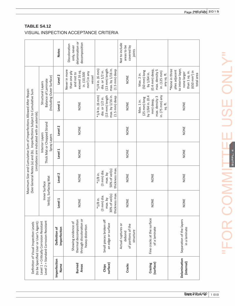
188
2015
SECTION 6
SU
PPL. 4
NB-23
TABLE S4.12VISUAL INSPECTION ACCEPTANCE CRITERIA
Defin
ition
of V
isual
Insp
ectio
n Le
vels
(to b
e Sp
ecifi
ed U
ser o
r Use
r’s A
gent
): Le
vel 1
= C
ritica
lly C
orro
sion
Resis
tant
Le
vel 2
= S
tand
ard
Corr
osio
n Re
sista
nt
Max
imum
Size
and
Cum
ulati
ve S
um o
f Im
perfe
ction
s Allo
wed
Afte
r Rep
air.
(See
Gen
eral
Not
es (a
) and
(b).
Impe
rfecti
ons S
ubje
ct to
Cum
ulati
ve S
um
Lim
itatio
ns a
re in
dica
ted
with
an
aste
risk)
.
Inne
r Sur
face
Ve
il(s)
, Sur
faci
ng M
at
Inte
rior L
ayer
s Th
ick
Mat
or C
hopp
ed S
tran
d Sp
ray
Laye
rs
Stru
ctur
al L
ayer
s Ba
lanc
e of
Lam
inat
e (In
clud
ing
Out
er S
urfa
ce)
Impe
rfec
tion
Nam
eDe
finiti
on o
f Im
perf
ectio
nLe
vel 1
Leve
l 2Le
vel 1
Leve
l 2Le
vel 1
Leve
l 2N
otes
Burn
ed
Area
s
Show
ing
evid
ence
of
ther
mal
dec
ompo
sition
th
roug
h di
scol
orati
on o
r he
avy
dist
ortio
n
NO
NE
NO
NE
NO
NE
NO
NE
NO
NE
Nev
er in
mor
e th
an o
ne p
ly
and
not t
o ex
ceed
16
sq.
in. (
10,5
00
mm
2 ) in
any
vess
el
Disc
olor
ation
on
ly, n
ever
de
lam
inati
on o
r de
com
positi
on
Chip
s su
rfac
e)Sm
all p
iece
s bro
ken
off
an e
dge
or su
rfac
e
*1/8
in.
(3 m
m) d
ia.
max
. by
30
% o
f vei
l(s)
thic
knes
s max
.
*1/8
in.
(3
mm
) dia
. m
ax. b
y
50%
of v
eil(s
) th
ickn
ess m
ax.
*1/4
in. (
6 m
m)
dia.
or 1
/2 in
. (1
3 m
m) l
engt
h m
ax. b
y 1/
16 in
. (1
.5 m
m) d
eep
*1/4
in. (
6 m
m)
dia.
or 1
/2 in
. (1
3 m
m) l
engt
h m
ax. b
y 1/
16 in
. (1
.5 m
m) d
eep
Crac
ks
Actu
al ru
ptur
es o
r de
bond
of
por
tions
of t
he
stru
ctur
e
NO
NE
NO
NE
NO
NE
NO
NE
NO
NE
NO
NE
Not
to in
clud
e ar
eas t
o be
co
vere
d by
jo
ints
Craz
ing
(sur
face
)Fi
ne c
rack
s at t
he su
rfac
e of
a la
min
ate
NO
NE
NO
NE
Max
. 1 in
.
(2
5 m
m) l
ong
by 1
/64
in. (
0.4
mm
) dee
p,
max
. den
sity
3 in
. (75
mm
) any
sq
. ft.
Max
. 2 in
.
(50
mm
) lon
g by
1/6
4 in
.
(0.4
mm
) dee
p,
max
. den
sity
5 in
. (12
5 m
m)
any
sq. ft
.
Dela
min
ation
(in
tern
al)
Sepa
ratio
n of
the
laye
rs
in a
lam
inat
eN
ON
EN
ON
EN
ON
EN
ON
EN
ON
E
*Non
e in
thre
e pl
ies a
djac
ent
to in
terio
r lay
er,
none
larg
er
than
1 sq
. in.
(6
50 m
m2 ) i
n to
tal a
rea
"FO
RC
OM
MIT
TEE
CO
MM
ITTE
EC
OM
MIT
TEE
SU
PPL. 4
CO
MM
ITTE
ES
UPPL. 4
US
EO
NLY
"
Page 218 of 400
Page 218 of 400
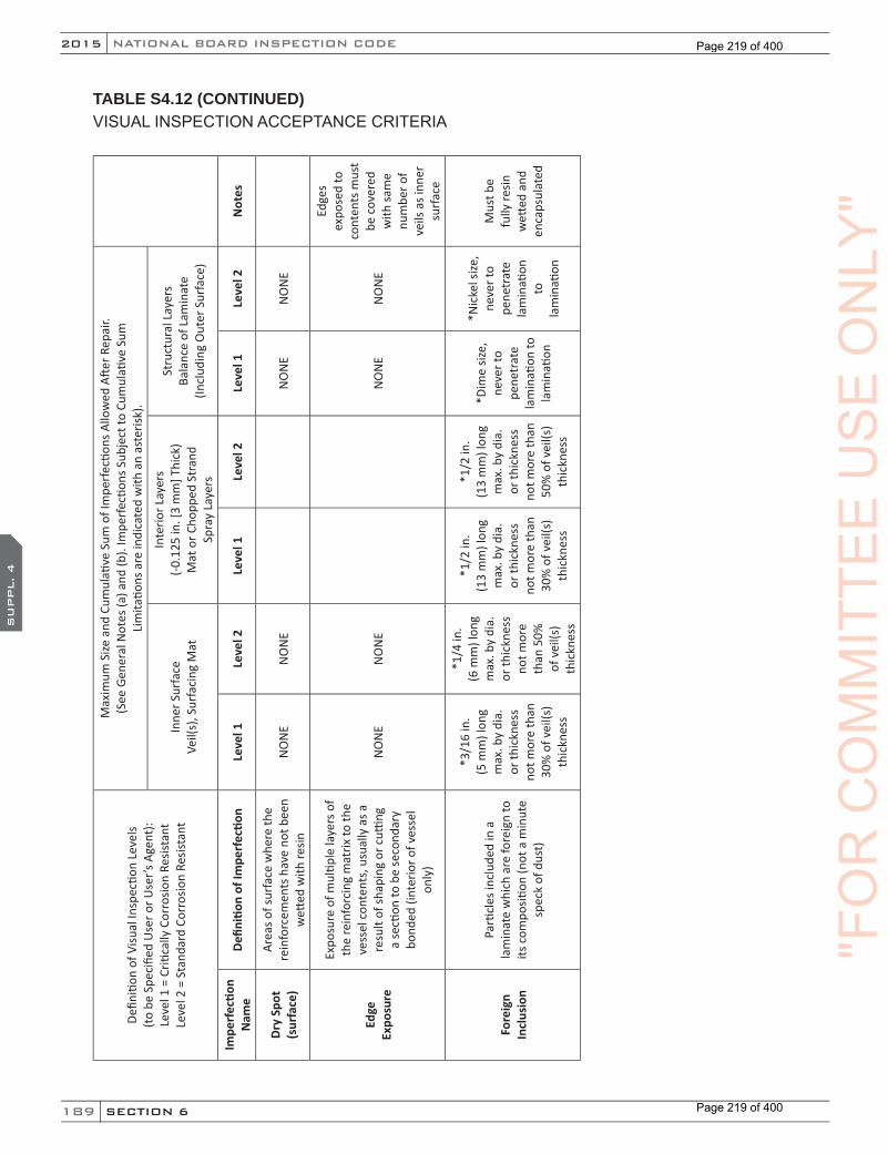
189
NATIONAL BOARD INSPECTION CODE2015
SECTION 6
SU
PPL. 4
TABLE S4.12 (CONTINUED)VISUAL INSPECTION ACCEPTANCE CRITERIA
Defin
ition
of V
isual
Insp
ectio
n Le
vels
(to b
e Sp
ecifi
ed U
ser o
r Use
r’s A
gent
): Le
vel 1
= C
ritica
lly C
orro
sion
Resis
tant
Le
vel 2
= S
tand
ard
Corr
osio
n Re
sista
nt
Max
imum
Size
and
Cum
ulati
ve S
um o
f Im
perfe
ction
s Allo
wed
Afte
r Rep
air.
(See
Gen
eral
Not
es (a
) and
(b).
Impe
rfecti
ons S
ubje
ct to
Cum
ulati
ve S
um
Lim
itatio
ns a
re in
dica
ted
with
an
aste
risk)
.
Inne
r Sur
face
Ve
il(s)
, Sur
faci
ng M
at
Inte
rior L
ayer
s (-0
.125
in. [
3 m
m] T
hick
) M
at o
r Cho
pped
Str
and
Spra
y La
yers
Stru
ctur
al L
ayer
s Ba
lanc
e of
Lam
inat
e (In
clud
ing
Out
er S
urfa
ce)
Impe
rfec
tion
Nam
eDe
finiti
on o
f Im
perf
ectio
nLe
vel 1
Leve
l 2Le
vel 1
Leve
l 2Le
vel 1
Leve
l 2N
otes
Dry
Spot
(s
urfa
ce)
Area
s of s
urfa
ce w
here
the
rein
forc
emen
ts h
ave
not b
een
wett
ed w
ith re
sinN
ON
EN
ON
EN
ON
EN
ON
E
Edge
Ex
posu
re
Expo
sure
of m
ultip
le la
yers
of
the
rein
forc
ing
mat
rix to
the
vess
el c
onte
nts,
usu
ally
as a
re
sult
of sh
apin
g or
cutti
ng
a se
ction
to b
e se
cond
ary
bond
ed (i
nter
ior o
f ves
sel
only
)
NO
NE
NO
NE
NO
NE
NO
NE
Edge
s ex
pose
d to
co
nten
ts m
ust
be c
over
ed
with
sam
e nu
mbe
r of
veils
as i
nner
su
rfac
e
Fore
ign
In
clus
ion
Parti
cles
incl
uded
in a
la
min
ate
whi
ch a
re fo
reig
n to
its
com
positi
on (n
ot a
min
ute
spec
k of
dus
t)
*3/1
6 in
. (5
mm
) lon
g m
ax. b
y di
a.
or th
ickn
ess
not m
ore
than
30
% o
f vei
l(s)
thic
knes
s
*1/4
in.
(6 m
m) l
ong
max
. by
dia.
or
thic
knes
s no
t mor
e th
an 5
0%
of v
eil(s
) th
ickn
ess
*1/2
in.
(13
mm
) lon
g m
ax. b
y di
a.
or th
ickn
ess
not m
ore
than
30
% o
f vei
l(s)
thic
knes
s
*1/2
in.
(13
mm
) lon
g m
ax. b
y di
a.
or th
ickn
ess
not m
ore
than
50
% o
f vei
l(s)
thic
knes
s
*Dim
e siz
e,
neve
r to
pene
trat
e la
min
ation
to
lam
inati
on
*Nic
kel s
ize,
neve
r to
pene
trat
e la
min
ation
to
la
min
ation
Mus
t be
fully
resin
w
etted
and
en
caps
ulat
ed
"FO
RC
OM
MIT
TEE
US
EO
NLY
"
Page 219 of 400
Page 219 of 400
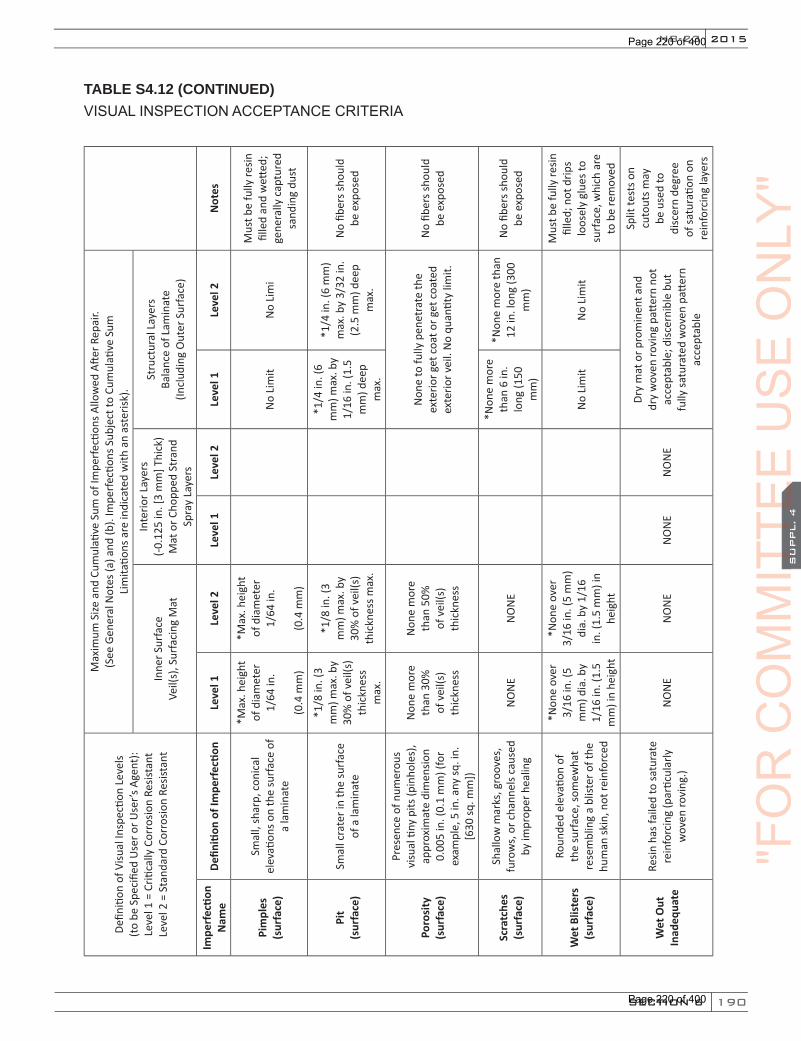
190
2015
SECTION 6
SU
PPL. 4
NB-23
TABLE S4.12 (CONTINUED) VISUAL INSPECTION ACCEPTANCE CRITERIA
Defin
ition
of V
isual
Insp
ectio
n Le
vels
(to b
e Sp
ecifi
ed U
ser o
r Use
r’s A
gent
): Le
vel 1
= C
ritica
lly C
orro
sion
Resis
tant
Le
vel 2
= S
tand
ard
Corr
osio
n Re
sista
nt
Max
imum
Size
and
Cum
ulati
ve S
um o
f Im
perfe
ction
s Allo
wed
Afte
r Rep
air.
(See
Gen
eral
Not
es (a
) and
(b).
Impe
rfecti
ons S
ubje
ct to
Cum
ulati
ve S
um
Lim
itatio
ns a
re in
dica
ted
with
an
aste
risk)
.
Inne
r Sur
face
Ve
il(s)
, Sur
faci
ng M
at
Inte
rior L
ayer
s (-0
.125
in. [
3 m
m] T
hick
) M
at o
r Cho
pped
Str
and
Spra
y La
yers
Stru
ctur
al L
ayer
s Ba
lanc
e of
Lam
inat
e (In
clud
ing
Out
er S
urfa
ce)
Impe
rfec
tion
Nam
eDe
finiti
on o
f Im
perf
ectio
nLe
vel 1
Leve
l 2Le
vel 1
Leve
l 2Le
vel 1
Leve
l 2N
otes
Pim
ples
(s
urfa
ce)
Smal
l, sh
arp,
con
ical
el
evati
ons o
n th
e su
rfac
e of
a
lam
inat
e
*Max
. hei
ght
of d
iam
eter
1/
64 in
.
(0.4
mm
)
*Max
. hei
ght
of d
iam
eter
1/
64 in
.
(0.4
mm
)
No
Lim
itN
o Li
mi
Mus
t be
fully
resin
fil
led
and
wett
ed;
gene
rally
cap
ture
d sa
ndin
g du
st
Pit
(sur
face
)Sm
all c
rate
r in
the
surf
ace
of a
lam
inat
e
*1/8
in. (
3 m
m) m
ax. b
y 30
% o
f vei
l(s)
thic
knes
s m
ax.
*1/8
in. (
3 m
m) m
ax. b
y 30
% o
f vei
l(s)
thic
knes
s max
.
*1/4
in. (
6 m
m) m
ax. b
y 1/
16 in
. (1.
5 m
m) d
eep
max
.
*1/4
in. (
6 m
m)
max
. by
3/32
in.
(2.5
mm
) dee
p m
ax.
No
fiber
s sho
uld
be e
xpos
ed
Poro
sity
(s
urfa
ce)
Pres
ence
of n
umer
ous
visu
al ti
ny p
its (p
inho
les)
, ap
prox
imat
e di
men
sion
0.00
5 in
. (0.
1 m
m) (
for
exam
ple,
5 in
. any
sq. i
n.
[630
sq. m
m])
Non
e m
ore
than
30%
of
vei
l(s)
thic
knes
s
Non
e m
ore
than
50%
of
vei
l(s)
thic
knes
s
Non
e to
fully
pen
etra
te th
e ex
terio
r get
coa
t or g
et c
oate
d ex
terio
r vei
l. N
o qu
antit
y lim
it.
No
fiber
s sho
uld
be e
xpos
ed
Scra
tche
s (s
urfa
ce)
Shal
low
mar
ks, g
roov
es,
furo
ws,
or c
hann
els c
ause
d by
impr
oper
hea
ling
NO
NE
NO
NE
*Non
e m
ore
than
6 in
. lo
ng (1
50
mm
)
*Non
e m
ore
than
12
in. l
ong
(300
m
m)
No
fiber
s sho
uld
be e
xpos
ed
Wet
Blis
ters
(s
urfa
ce)
Roun
ded
elev
ation
of
the
surf
ace,
som
ewha
t re
sem
blin
g a
blist
er o
f the
hu
man
skin
, not
rein
forc
ed
*Non
e ov
er
3/16
in. (
5 m
m) d
ia. b
y 1/
16 in
. (1.
5 m
m) i
n he
ight
*Non
e ov
er
3/16
in. (
5 m
m)
dia.
by
1/16
in
. (1.
5 m
m) i
n he
ight
No
Lim
itN
o Li
mit
Mus
t be
fully
resin
fil
led;
not
drip
s lo
osel
y gl
ues t
o su
rfac
e, w
hich
are
to
be
rem
oved
Wet
Out
In
adeq
uate
Resin
has
faile
d to
satu
rate
re
info
rcin
g (p
artic
ular
ly
wov
en ro
ving
.)N
ON
EN
ON
EN
ON
EN
ON
E
Dry
mat
or p
rom
inen
t and
dr
y w
oven
rovi
ng p
atter
n no
t ac
cept
able
; disc
erni
ble
but
fully
satu
rate
d w
oven
patt
ern
acce
ptab
le
Split
test
s on
cuto
uts m
ay
be u
sed
to
disc
ern
degr
ee
of sa
tura
tion
on
rein
forc
ing
laye
rs
"FO
RC
OM
MIT
TEE
CO
MM
ITTE
EC
OM
MIT
TEE
SU
PPL. 4
CO
MM
ITTE
ES
UPPL. 4
US
EO
NLY
"
Page 220 of 400
Page 220 of 400
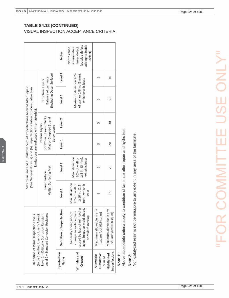
191
NATIONAL BOARD INSPECTION CODE2015
SECTION 6
SU
PPL. 4
TABLE S4.12 (CONTINUED)VISUAL INSPECTION ACCEPTANCE CRITERIA
Defin
ition
of V
isual
Insp
ectio
n Le
vels
(to b
e Sp
ecifi
ed U
ser o
r Use
r’s A
gent
): Le
vel 1
= C
ritica
lly C
orro
sion
Resis
tant
Le
vel 2
= S
tand
ard
Corr
osio
n Re
sista
nt
Max
imum
Size
and
Cum
ulati
ve S
um o
f Im
perfe
ction
s Allo
wed
Afte
r Rep
air.
(See
Gen
eral
Not
es (a
) and
(b).
Impe
rfecti
ons S
ubje
ct to
Cum
ulati
ve S
um
Lim
itatio
ns a
re in
dica
ted
with
an
aste
risk)
.
Inne
r Sur
face
Ve
il(s)
, Sur
faci
ng M
at
Inte
rior L
ayer
s (-0
.125
in. [
3 m
m] T
hick
) M
at o
r Cho
pped
Str
and
Spra
y La
yers
Stru
ctur
al L
ayer
s Ba
lanc
e of
Lam
inat
e (In
clud
ing
Out
er S
urfa
ce)
Impe
rfec
tion
Nam
eDe
finiti
on o
f Im
perf
ectio
nLe
vel 1
Leve
l 2Le
vel 1
Leve
l 2Le
vel 1
Leve
l 2N
otes
Wrin
kles
and
Cr
ease
s
Gene
rally
line
ar, a
brup
t ch
ange
s in
surf
ace
plan
e ca
used
by
laps
of r
einf
orci
ng
laye
rs, i
rreg
ular
mol
d sh
ape,
or
Myl
ar®
over
lap
Max
. dev
iatio
n 20
% o
f wal
l or
1/16
in. (
1.5
mm
), w
hich
is
leas
t
Max
. dev
iatio
n 20
% o
f wal
l or
1/8
in. (
3 m
m),
whi
ch is
leas
t
Max
imum
dev
iatio
n 20
%
of w
all o
r 1/8
in. (
3 m
m),
whi
chev
er is
leas
t
Not
to c
ause
a
cum
ulati
ve
linea
r def
ect
(out
side
defe
ct
addi
ng to
insid
e de
fect
)
Allo
wab
le
Cum
ulati
ve
Sum
of
High
light
ed
Impe
rfec
tions
Max
imum
allo
wab
le in
any
sq
uare
foot
(0.9
sq. m
)3
53
55
5
Max
imum
allo
wab
le in
any
sq
uare
yar
d (0
.8 sq
. m)
1620
2030
3040
Not
e 1:
A
bove
acc
epta
ble
crite
ria a
pply
to c
ondi
tion
of la
min
ate
afte
r rep
air a
nd h
ydro
test
.N
ote
2:N
on-c
atal
yzed
resi
n is
not
per
mis
sibl
e to
any
ext
ent i
n an
y ar
ea o
f the
lam
inat
e.
"FO
RC
OM
MIT
TEE
US
EO
NLY
"
Page 221 of 400
Page 221 of 400
192
2015
SECTION 6
SU
PPL. 4
NB-23
S4.13 PRESSURE AND ACOUSTIC EMISSION TESTS
All vessels subject to repairs other than those defined in NBIC Part 3, S4.16.4 shall be tested in accordance with the requirements of the original code of construction. In addition, all structural repairs and alterations shall be pressure tested. All vessels acoustic emission tested as required by the original code of construction shall be retested during the pressure test concentrating on the repaired or altered part of the vessel.
S4.13.1 PRESSURE GAGES, MEASUREMENT, AND EXAMINATION AND TEST EQUIPMENT
The calibration of pressure gages, measurement, examination and test equipment, and documentation of calibration shall be performed as required by the applicable standard used for construction.
S4.14 ACCEPTANCE INSPECTION
Before signing the appropriate NBIC report form, the Inspector shall:
a) review the drawings;
b) ensure the secondary bonding was performed in accordance with the original code of construction;
c) witness any pressure or acoustic emission test;
d) ensure that the required nondestructive examinations have been performed satisfactorily; and
e) that the other functions necessary to assure compliance with the requirements of this code have been performed.
S4.14.1 STAMPING
Stamping requirements for FRP vessels are identified in NBIC Part 3, Section 5.
S4.14.2 DOCUMENTATION
Documentation requirements for FRP vessels are identified in NBIC Part 3, Section 5.
S4.14.3 REGISTRATION OF DOCUMENTATION
Organizations performing repairs or alterations under an “R” stamp program shall register such repairs or alterations with the National Board.
S4.14.4 DISTRIBUTION OF DOCUMENTATION
Distribution of documentation requirements for FRP vessels are identified in NBIC Part 3, Section 5.
S4.15 PRESSURE TESTING FOR REPAIRS
Except as permitted in e) below, the following requirements apply to all repairs to pressure-retaining items:
a) Repairs shall be pressure tested to 110% of the maximum allowable working pressure stamped on the pressure-retaining item using water or other liquid medium. The Certificate Holder is responsible for all activities relating to pressure testing of repairs.
"FO
RC
OM
MIT
TEE
CO
MM
ITTE
EC
OM
MIT
TEE
SU
PPL. 4
CO
MM
ITTE
ES
UPPL. 4
US
EO
NLY
"
Page 222 of 400
Page 222 of 400

193
NATIONAL BOARD INSPECTION CODE2015
SECTION 6
SU
PPL. 4
b) Replacement parts used in repairs shall be pressure tested at the maximum allowable working pressure indicated on the pressure-retaining item being repaired.
c) During a pressure test, where the test pressure will exceed the set pressure of the pressure relief device, the device shall be prepared as recommended by the device manufacturer.
d) Hold time for the examination by the Inspector shall be the time necessary for the Inspector to conduct the examination.
e) When pressure testing using liquids is not practical, other methods shall be used as follows:
1) The pressure test may be a pneumatic test provided the Certificate Holder has the concurrence of the Inspector, the jurisdictional authority where required, and the owner. Precautionary requirements of the applicable section of the original code of construction shall be followed. In addition, a pneumatic test shall always be monitored by acoustic emission examination.
2) For vessels designed for vacuum, a vacuum test shall be carried out to the original test vacuum level of the vessel. During the vacuum test, the vacuum source may be left connected to the vessel to compensate for leakage at fittings. All vessels acoustic emission tested, as required by the original code of construction, shall be retested during the vacuum test concentrating on the repaired or altered part of the vessel.
S4.16 ADDITIONAL REQUIREMENTS FOR REPAIRS
S4.16.1 SCOPE
This section provides additional requirements for repairs to pressure-retaining items and shall be used in conjunction with NBIC Part 3, S4.1 through S4.14 and S4.18.
S4.16.2 DRAWINGS
Drawings shall be prepared or modified to describe the repair. Drawings shall include sufficient information to satisfactorily perform the repair.
S4.16.3 REPAIR PLAN
When repairs other than those defined in NBIC Part 3, S4.16.4 are being made to ASME Section X or RTP-1 stamped equipment, the user shall prepare or cause to have prepared a detailed plan covering the scope of the repair.
a) Engineer Review and Certification
The repair plan shall be reviewed and certified by an engineer meeting the ASME Section X or RTP-1 criteria for an engineer certifying ASME Section X or RTP-1 compliance of the appropriate calculations contained in the Fabricator’s Design Report. The review and certification shall be such to ensure that the work involved in the repair is compatible with the User’s Design Specification or User’s Basic Requirements Specification and the Fabricator’s Design Report. The certification shall also include any drawings and calculations prepared as part of the repair plan.
Note: The engineer qualification criteria of the Jurisdiction, where the pressure vessel is installed should be verified before selecting the Certifying Engineer. The certification shall also include any drawings and calculations prepared as part of the repair plan.
"FO
RC
OM
MIT
TEE
US
EO
NLY
"
Page 223 of 400
Page 223 of 400

194
2015
SECTION 6
SU
PPL. 4
NB-23
b) Authorized Acceptance
Following review and certification, the repair plan shall be submitted to the Inspector for his review and acceptance. Repairs to pressure-retaining items shall not be initiated without the authorization of the Inspector. Subject to acceptance of the Jurisdiction, the Inspector may give prior approval for routine repairs, provided the Inspector assures that the Certificate Holder has acceptable procedures covering the repairs.
S4.16.4 ROUTINE REPAIRS
Prior to performing routine repairs, the Certificate Holder should determine that routine repairs are acceptable to the Jurisdiction where the work is to be performed.
a) Acceptable routine repairs are listed below:
1) The addition or repair of non-load bearing attachments to pressure-retaining items where post curing is not required.
2) Replacement and repair of damaged corrosion liner areas in shells and heads shall not exceed 100 sq. in. (65 sq. cm) and not exceed the original corrosion liner thickness.
b) Routine repairs may be performed under the Certificate Holder’s quality system program; however, the requirement for in-process involvement of the Inspector and stamping are waived. (See NBIC Part 3, Section 5).
c) The process of controlling and implementing routine repairs shall be documented in the Certificate Holder’s quality system program.
d) Routine repairs shall be documented on a Form R-1 with a statement on line 10, Remarks: “Routine Repair.”
S4.16.5 REPAIR METHODS
The repair methods shall be acceptable to the Inspector. Some methods of repair are contained in NBIC Part 3, S4.18.
S4.17 ADDITIONAL REQUIREMENTS FOR ALTERATIONS
S4.17.1 SCOPE
This Section provides additional requirements for alterations to pressure-retaining items, and shall be used in conjunction with NBIC Part 3, S4.1 through S4.14 and S4.18.
S4.17.2 DESIGN
The Certificate Holder performing alterations shall establish controls to ensure that all required design information, applicable drawings, design calculations, specifications and instructions are prepared, obtained, controlled, and interpreted to provide the basis for an alteration in accordance with the original code of construction. When a Fabricator’s Data Report is required by the original code of construction, a copy of the original data report shall be obtained for use in the design of the alteration. When the original Fabricator’s Data Report cannot be obtained, agreements on the method of establishing design basis for the alteration shall be obtained from the Inspector and the Jurisdiction.
"FO
RC
OM
MIT
TEE
CO
MM
ITTE
EC
OM
MIT
TEE
SU
PPL. 4
CO
MM
ITTE
ES
UPPL. 4
US
EO
NLY
"
Page 224 of 400
Page 224 of 400
195
NATIONAL BOARD INSPECTION CODE2015
SECTION 6
SU
PPL. 4
S4.17.3 ALTERATION PLAN
The user shall prepare, or cause to have prepared, a detailed plan covering the scope of the alteration.
a) Engineer Review and Certification
The alteration plan shall be reviewed and certified by an engineer meeting the ASME Section X or RTP-1 criteria for an engineer certifying ASME Section X or RTP-1 compliance of the appropriate calculations contained in the Fabricator’s Design Report. The review and certification shall be such as to ensure that the work involved in the alteration is compatible with the user’s design specification and the Fabricator’s Data Report.
Note: The engineer qualification criteria of the jurisdiction where the pressure vessel is installed should be verified before selecting the certifying engineer.
b) Authorized Acceptance
Following review and certification, the alteration plan shall be submitted to the Inspector for his review and acceptance. Alterations to pressure-retaining items shall not be initiated without the authorization of the Inspector.
S4.17.4 CALCULATIONS
A set of calculations shall be completed prior to the start of any physical work. All design work shall be completed by an organization experienced in the design portion of the standard used for the construction of the item. All calculations for ASME Code Section X and RTP-1 alterations shall be certified by an engineer meeting the ASME Section X criteria for an engineer certifying ASME Section X compliance of the calculations contained in the Fabricator’s Design Report. All calculations shall be made available for review by the Inspector.
Note: The engineer qualification criteria of the jurisdiction where the pressure vessel is installed should be verified before selecting the certifying engineer.
S4.17.5 RE-RATING
a) Re-rating of a pressure-retaining item by increasing the maximum allowable working pressure (internal or external) or temperature , or decreasing the minimum temperature shall be done only after the following requirements have been met to the satisfaction of the Jurisdiction at the location of the installation:
1) Revised calculations verifying the new service conditions shall be prepared in accordance with the Certificate Holder’s Quality Control System. Re-rating calculations for ASME Code Section X and RTP-1 vessels shall be performed by a Professional Engineer experienced in the design of reinforced plastic pressure vessels;
2) All re-rating shall be established in accordance with the requirements of the construction standard to which the pressure-retaining item was built;
3) Current inspection records shall verify that the pressure-retaining item is satisfactory for the proposed service conditions;
4) The pressure-retaining item shall be pressure tested, as required, for the new service conditions.
b) This code does not provide rules for de-rating pressure-retaining items; however, when the MAWP and/or allowable temperature of a pressure-retaining item is reduced, the Jurisdiction wherein the object is installed should be contacted to determine if specific procedures should be followed.
"FO
RC
OM
MIT
TEE
US
EO
NLY
"
Page 225 of 400
Page 225 of 400
196
2015
SECTION 6
SU
PPL. 4
NB-23
S4.17.6 PRESSURE TESTING
Except as permitted in g) below, the following requirements apply for pressure testing of alterations to pressure-retaining items:
a) When the alteration activity involves the installation of a replacement part and/or the alteration will impact the design pressure, the design temperature, or the design rated capacity, a pressure test, as required by the original code of construction, shall be conducted. An acoustic emission test is also required if the original vessel was so tested, unless a nozzle whose diameter is one-tenth the vessel diameter or less is being added.
The Certificate Holder is responsible for all activities related to pressure testing of replacement parts. The pressure test may be performed at the point of manufacture or point of installation.
b) The pressure test of replacement parts and connecting secondary bonds shall be tested at 1.1 times the maximum allowable working pressure or the original test pressure, whichever is greatest.
c) During the pressure test, where the test pressure will exceed the set pressure of the pressure relief device, the device shall be prepared as recommended by the device manufacturer.
d) The liquid temperature used for pressure testing shall not be less than 40°F (4°C) nor more than 120°F (49°C) unless the original pressure test was conducted at a higher temperature. If an acoustic emission examination is being conducted, the temperature of the test liquid shall not vary by more than plus 5°F (-15°C) or minus 10°F (-12°C).
e) Hold time for the pressure test shall be a minimum of 30 minutes with an acoustic emission examination or a minimum of four hours without an acoustic emission examination. The following procedure shall be used to retest a vessel that has been tested under the provisions of Article 6 of ASME Section X and has subsequently been repaired.
1) Load the vessel as specified in Article 6 of ASME Section X without monitoring for acoustic emission.
2) Hold the maximum load for at least 30 minutes.
3) Condition the vessel by holding at reduced load as required by Section V, Article 11, T-1121.
4) Retest the vessel as required by this supplement.
5) The vessel shall be judged against the evaluation criteria for subsequent loadings.
f) Hold time for the examination by the Inspector shall be the time necessary for the Inspector to conduct the inspection.
g) When pressure testing using liquids is not practical, other methods shall be used as follows:
1) The pressure test may be a pneumatic test provided the Certificate Holder has the concurrence of the Inspector, the jurisdictional authority where required, and the owner. Precautionary requirements of the applicable section of the original code of construction shall be followed.
2) For vessels designed for vacuum, a vacuum test shall be carried out to as close as practical to the design vacuum level of the vessel. During the vacuum test the vacuum source may be left connected to the vessel to compensate for leakage at fittings. All vessels originally acoustic emission tested shall be retested during the vacuum test concentrating on the repaired or altered part of the vessel.
"FO
RC
OM
MIT
TEE
CO
MM
ITTE
EC
OM
MIT
TEE
SU
PPL. 4
CO
MM
ITTE
ES
UPPL. 4
US
EO
NLY
"
Page 226 of 400
Page 226 of 400
197
NATIONAL BOARD INSPECTION CODE2015
SECTION 6
SU
PPL. 4
S4.18 REPAIR AND ALTERATION METHODS
S4.18.1 GENERAL REQUIREMENTS
a) In general, when a defective or damaged vessel wall is to be repaired, the total structural laminate sequence of laminate construction removed as part of the repair shall be replaced. The replacement laminate shall provide structural properties meeting or exceeding the requirement of the original construction standard. Moreover, when damage includes the corrosion barrier, a corrosion barrier of the same type, which shall meet or exceed the barrier properties of the original construction, shall replace the corrosion barrier removed as part of the repair.
b) The repair or alteration shall meet the requirements of the original construction standard.
S4.18.2 CLASSIFICATION OF REPAIRS
a) Vessel repairs shall be classified into the following types:
1) Type 1a — Corrosion barrier repairs;
2) Type 1b — Corrosion barriers with precision bores;
3) Type 2 — Corrosion barrier and interior structural layer repairs;
4) Type 3 — External structural layer repairs;
5) Type 4 — Alterations;
6) Type 5 — Miscellaneous general external repairs or alterations;
7) Type 6 — Thermoplastic repairs; and
8) Type 7 — Gel coat repairs.
b) Each type of repair shall have its own corresponding general repair procedure as given in the following paragraphs.
S4.18.2.1 TYPE 1A — REPAIR OF THE CORROSION BARRIER
a) A corrosion barrier that has been exposed to a process may be permeated to the point that in some cases the entire corrosion barrier laminate may need to be removed.
b) After the Inspector has verified that the repair procedure is acceptable, the repair shall be performed by the Certificate Holder as follows:
1) Surface Preparation
a. The surface area that is damaged must be removed by abrasive blasting or grinding, to remove contaminated laminate and expose sound laminate. The edge of the repaired area must have a bevel of 2 in. (50 mm) minimum.
b. Note that any cracks, delaminations, or permeated surface must be removed. An adequate size abrasive, or proper sanding disc must be used to obtain a 0.002 to 0.003 in. (0.05 to 0.08 mm) anchor pattern.
c. Preparation of any surface requires that basic rules, common to all substrates, be followed.These rules are as outlined below:
"FO
RC
OM
MIT
TEE
US
EO
NLY
"
Page 227 of 400
Page 227 of 400
198
2015
SECTION 6
SU
PPL. 4
NB-23
1. Surface must be free of contaminants;
2. Surface must be structurally sound;
3. Surface must have adequate anchor pattern;
4. Surface must be dry;
5. Surface must be primed with recommended primer.
Note: After the surface has been properly prepared, it must be kept clean and dry until laminating can be started. Dust, moisture, or traces of oil that come in contact with the surface may act as a mold release or inhibit the cure and prevent a good secondary bond.
2) Applying Test Patches to Verify Adequate Surface Preparation
a. Test patches should be applied to any substrate that will require a secondary bond to determine the integrity of the primer bond prior to the application of the laminate.
b. The subsequent steps shall be followed:
1. Apply the primer (0,003 -0.005 in. (0.08 to 0.13 mm)) to the prepared surface, and allow primer to cure.
2. Coat the primed surface with the same resin to be used in the laminate repair. Apply 4 in. (100 mm) x 14 in. (360 mm) piece of polyester, such as Mylar®, strip to one edge of primed area. Allow the polyester film to protrude from beneath the patch.
3. Apply two layers of 1-1/2 oz/sq. ft (0.46 kg/sq. m) chopped strand mat saturated with the same resin that will be used for the repair. Mat shall be 12 in. (305 mm) x 12 in. (305 mm) square.
4. Allow the mat layers to cure completely, this may be verified by checking the hardness of the laminate.
5. Pry patch from surface using a screwdriver, chisel, or pry bar.
6. A clean separation indicates a poor bond.
7. Torn patch laminate or pulled substrate indicates that the bond is acceptable.
c. If the bond is not adequate, go back to step a) and repeat the procedure.
Note: If the repair area is smaller than the test patch dimensions, decrease the test patch size accordingly.
d. As a last resort, if the previous procedure does not provide an adequate bond, the permeated laminate must be handled differently using the following procedure:
1. Hot water wash the equipment.
2. Abrasive blast with #3 sand, or equal, and allow to completely dry.
3. Prime with the recommended primer, an area 12 in. (305 mm) x 12 in. (305 mm) and apply a test patch.
4. Prime a second spot 12 in. (305 mm) x 12 in. (305 mm) and prime with a recommended epoxy resin primer.
5. Allow this primer to cure.
"FO
RC
OM
MIT
TEE
CO
MM
ITTE
EC
OM
MIT
TEE
SU
PPL. 4
CO
MM
ITTE
ES
UPPL. 4
US
EO
NLY
"
Page 228 of 400
Page 228 of 400
199
NATIONAL BOARD INSPECTION CODE2015
SECTION 6
SU
PPL. 4
6. Water wash, dry, and lightly abrasive blast the epoxy primer.
7. Apply the test patches to both areas.
e. Pull both test patches after they are fully cured.
f. If both test patches are good, prime the vessel with the preferred primer. If only one test patch is good, prime the vessel with the successful primer.
Note: If the repair area is smaller than the test patch dimensions, decrease the test patch size accordingly.
g. If neither patch bonds, the vessel is probably not capable of bonding a patch and shall not be repaired.
3) Laminate Repair
a. Repairs can be accomplished by adding back the correct corrosion barrier surface material as specified on the Fabricator’s design drawings.
b. All repairs shall be made with the same type of resin and reinforcement materials used to fabricate the original vessel corrosion barrier. Laminate quality shall be in accordance with Table S4.12. The acceptance criteria shall be as agreed by the Certificate Holder and owner or as required by the code of construction.
1. Apply the selected primer (0.003 -0.005 in. (0.08 to 0.13 mm)) and allow to dry to the touch.
2. Continue with the specified laminate using the proper resin and cure. The first layer of chopped strand mat used in the repair shall extend a minimum of 1 in. (25 mm) past the damaged area. The following chopped strand mat layer shall extend a minimum of 1 in. (25 mm) past the first layer, (in this manner, the entire area that was removed will now be filled with the mat layers. If additional layers are required to fill the removed surface, they must be applied), followed by the specified layer(s) of veil. The veil(s) shall extend a minimum of 1 in. (25 mm) past the last chopped strand mat layer.
3. Apply a final coat of resin over entire surfacing veil. This final coat should contain a small amount of wax to prevent air contact, which might inhibit the cure. Allow laminate to achieve the manufacturer’s recommended Barcol hardness before finalizing the repair.
Note: Apply heat to finalize the cure if hardness is not achieved.
S4.18.2.2 TYPE 1B — REPAIR OF THE CORROSION BARRIER FOR VESSELS WITH PRECISION BORES
Vessels with precision bores are commonly used when a device is installed inside the vessel and a seal between the device and the inside diameter is required. A corrosion barrier of a precision bore vessel is (susceptible) to scratching and damage that may affect performance and service life of the vessel or the device placed inside the vessel. Many times this damage may extend into areas of the vessel that cannot be reached. Before starting, ensure that the damaged area can be reached. After the Inspector has verified that the repair procedure is acceptable, the repair shall be performed by the Certificate Holder as follows:
a) Surface Preparation
1) The surface area that is damaged must be removed by abrasive blasting or grinding, to expose sound laminate. No more than 0.020 in. (0.51 mm) may be removed from the wall of the vessel. The repaired area shall be beveled into the good areas surrounding the damage.
"FO
RC
OM
MIT
TEE
US
EO
NLY
"
Page 229 of 400
Page 229 of 400
200
2015
SECTION 6
SU
PPL. 4
NB-23
2) Note that any cracks, delaminations, or permeated surfaces must be removed. If the damage is deeper than the corrosion barrier and the material removed reaches the structural laminate, the vessel is not repairable. An adequate size abrasive, or proper sanding disc must be used to obtain a 0.003 to 0.005 in.(0.05 to 0.08 mm) anchor pattern to the area that requires the repair.
3) Preparation of any surface requires that basic rules, common to all substrates, be followed. These rules are as outlined below:
a. Surface must be free of contaminants;
b. Surface must be structurally sound;
c. Surface must have adequate anchor pattern;
d. Surface must be dry;
e. Surface must be primed with recommended primer.
Note: After the surface has been properly prepared, it must be kept clean and dry until laminating can be started. Dust, moisture, or traces of oil that come in contact with the surface may act as a mold release or act to inhibit the cure and prevent a good secondary bond. Laminating should be done within two hours of the surface preparation.
b) Applying Test Patches to Verify Adequate Surface Preparation
1) Test patches may be applied to any substrate that will require a secondary bond to determine the integrity of the bond prior to the application of the laminate.
2) The subsequent steps shall be followed:
a. Apply the primer ((0.003 to 0.005 in. [0.08 to 0.13 mm]) to the prepared surface, and allow primer to cure;
b. Coat the surface with the same resin to be used in the laminate repair. Apply a small strip of polyester film, such as Mylar®, strip to one edge of primed area. Allow the polyester film to protrude from beneath the patch;
c. Apply two layers of 1-1/2 oz. per sq. ft. (0.46 kg per sq. m) chopped strand mat saturated with the same resin that will be used for the repair;
d. Allow the mat layers to cure completely; this may be verified by checking the hardness of the laminate. If required, heat may be used to cure the material providing it is compatible with the initialresin used in the fabrication of the vessel;
e. Pry patch from surface using a screwdriver, chisel, or pry bar;
f. A clean separation indicates a poor bond;
g. Torn patch laminate or pulled substrate indicates that the bond is acceptable;
h. If the bond is not adequate, go back to step a) and repeat the procedure again.
Note: If the repair area is smaller than the test patch dimensions, decrease the test patch size accordingly.
3) If neither patch bonds, the vessel is probably not capable of bonding a patch and shall not be repaired.
"FO
RC
OM
MIT
TEE
CO
MM
ITTE
EC
OM
MIT
TEE
SU
PPL. 4
CO
MM
ITTE
ES
UPPL. 4
US
EO
NLY
"
Page 230 of 400
Page 230 of 400

201
NATIONAL BOARD INSPECTION CODE2015
SECTION 6
SU
PPL. 4
c) Laminate repair
1) Repairs can be accomplished by adding back the correct corrosion barrier surface material as specified on the Fabricator’s design drawings.
2) When possible, repairs shall be made with the same type of resin and reinforcement materials used to fabricate the original vessel corrosion barrier. Laminate quality shall be in accordance with TableS4.12, or the original code of construction. However, when the original material of construction was gelled and post cured at elevated temperatures, using the same resin may not be possible. In this case an alternate resin system may be used.
a. Apply the selected primer (0.003 to 0.005 in. [0.08 to 0.13 mm]) (as required for polyester and vinyl ester resins) and allow to dry to the touch.
b. Continue with the specified laminate using the proper resin and cure. The first layer of non-woven polyester veil used in the repair shall extend to the exact edge of the damaged area. If additional layers are required to fill the removed surface, they must be applied, followed by the specified layer(s) of veil.
c. Apply a final coat of resin over entire surfacing veil. If this final coat is a vinyl ester or polyester material, it should contain a small amount of wax to prevent air contact, which might inhibit the cure. Allow laminate to achieve the manufacturer’s recommended Barcol hardness before finalizing the repair.
Note: Apply heat to finalize the cure if hardness is not achieved.
d. After the repair has been properly cured, remove any excess material with the appropriate sanding tools to obtain a smooth surface that blends into the surrounding area. Care should be taken to ensure that the final inside diameter of the repaired area matches that of the surrounding area and also conforms to the original supplier’s specifications.
S4.18.2.3 TYPE 2 — CORROSION BARRIER AND INTERNAL STRUCTURAL LAYER REPAIRS
a) The procedure for the Type 1a repair must be followed with the exception of additional layers (structural layers) that must be removed if the structure is also damaged. The repair area must be tapered similar to the Type 1a, and all of the structural layers must be replaced making sure that the mat layers increase in length and width by at least 1 in. (25 mm). The structural laminate sequence and thickness must be approved by the Inspector, and proper calculations and the repair plan must be reviewed and approved by a Professional Engineer familiar with the work involved prior to the job.
b) Surface preparation, priming, and laminate repair must be done per Type 1a procedure.
S4.18.2.4 TYPE 3 — EXTERNAL STRUCTURAL LAYER REPAIRS
a) Surface Preparation
1) The surface area that is damaged is to be repaired by removing the damaged area either by abrasive blasting or grinding to expose sound laminate. The repair area must have a bevel of 2 in. (50 mm) minimum. The ground or blasted surface must extend a minimum of 4 in. (100 mm) past the damaged area into the sound solid structural laminate (making sure that no layers are removed in these 4 in. (100 mm), or as calculated accordingly).
2) Note that any cracks or delaminations must be removed. An adequate size abrasive or proper sanding disc must be used to obtain a (0.003 to 0.005 in. [0.05 to 0.08 mm]) anchor pattern.
"FO
RC
OM
MIT
TEE
US
EO
NLY
"
Page 231 of 400
Page 231 of 400
202
2015
SECTION 6
SU
PPL. 4
NB-23
3) Preparation of any surface requires that basic rules, common to all substrates, be followed. These rules are as outlined below:
a. Surface must be free of contaminants;
b. Surface must be structurally sound;
c. Surface must have adequate anchor pattern;
d. Surface must be dry; and
e. Surface must be primed with recommended primer.
Note: After the surface has been properly prepared, it must be kept clean and dry until laminating can be started. Dust, moisture, or traces of oil that come in contact with the surface may act as a mold release or inhibit the cure and prevent a good secondary bond. Laminating should be done within two hours of the surface preparation.
b) Applying Test Patches to Verify Adequate Surface Preparation
1) Test patches may be applied to any substrate that will require a secondary bond to determine the integrity of the primer bond prior to the application of the laminate.
2) The subsequent steps shall be followed:
a. Apply the primer (0.003 to 0.005 in. [0.08 to 0.13 mm]) to the prepared surface, and allow primer to cure;
b. Coat the primed surface with resin to be used in the repair. Apply a 4 in. (100 mm) x 14 in. (350 mm) Mylar® strip to one edge of primed area. Allow polyester film to protrude from beneath the patch;
c. Apply two layers of 1-1/2 oz. per sq. ft. (458 g/m2) chopped strand mat saturated with the specified resin that will be used for the repair. Mat shall be 12 in. (305 mm) x 12 in. (305 mm) square;
d. Allow to cure completely; this may be verified by checking the hardness of the laminate;
e. Pry patch from surface using a screwdriver, chisel, or pry bar;
f. A clean separation indicates a poor bond;
g. Torn patch laminate or pulled substrate indicates that the bond is acceptable; and
h. If the bond is not adequate, go back to step one and prepare the surface again.
Note: If the repair area is smaller than the test patch dimensions, decrease the test patch size accordingly.
c) Laminate Repair
1) Repairs can be accomplished by adding back the correct equivalent contact molded laminate material as specified on the Fabricator’s design drawings, or in the Repair Plan.
2) All repairs shall be made with the same type of resin and reinforcement materials used to fabricate the original vessel. Laminate quality shall be in accordance with the original construction code as specified in the vessel drawings and specifications.
a. Apply the selected primer (0.003 to 0.005 in. [0.08 to 0.13 mm]) and allow to dry to the touch.
"FO
RC
OM
MIT
TEE
CO
MM
ITTE
EC
OM
MIT
TEE
SU
PPL. 4
CO
MM
ITTE
ES
UPPL. 4
US
EO
NLY
"
Page 232 of 400
Page 232 of 400
203
NATIONAL BOARD INSPECTION CODE2015
SECTION 6
SU
PPL. 4
b. Continue with the specified laminate using the proper resin and cure.
c. Fill the removed layers with the same sequence as the original structural thickness, making sure that the layers are increasingly larger as the laminate is applied (in the case of filament wound structure, an equivalent contact molded thickness must be used for the repair calculations). The first bond of the repair shall cover one degree times the width in the axial direction and shall be centered. The repair shall extend completely around the circumference using contact molded procedures as set forth in the code of construction.
d. After the area is completely filled with the proper laminate, a reinforcing laminate shall be applied over the entire surface with a minimum overlap of 4 in. (100 mm) over the original shell, or as shown in the calculations, whichever is greater. This overlay thickness shall be calculated in the same way as the reinforcing pad of a nozzle with the diameter equal to the damaged area. The design shall be in accordance with the original construction code. Allow the laminate to achieve the manufacturer’s recommended Barcol hardness before finalizing the repair.
Note: Apply heat to finalize the cure if hardness is not achieved.
e. A pressure test shall be performed per NBIC Part 3, 4.4.1.
S4.18.2.5 TYPE 4 — ALTERATIONS
a) Alterations, such as the addition of a nozzle or supports, must be designed according to the original construction standard. In the case of nozzles, the internal overlay is required according to ASME RTP-1 Figure 4-8 or 4-9 (overlay “ti”). The procedure for preparing the inside surface is the same as the Type 1 repair. The external reinforcing pad shall be designed and installed according to the original construction standard. Surface preparation for the external overlay shall be according to the Type 3 repair procedure.
b) After the alteration is completed, a pressure test shall be performed in accordance with NBIC Part 3, 4.4.1. As an option, an Acoustic Emission test can be performed to monitor the repaired area during the pressure test.
S4.18.2.6 TYPE 5 — MISCELLANEOUS GENERAL EXTERNAL REPAIRS OR ALTERATIONS
External repairs or alterations that are performed on nonpressure retaining parts, shall be calculated according to the original construction standard. The Inspector and the Professional Engineer must review and approve such modifications. All repairs and alterations shall be done according to the Type 3 repair procedure, with the exception of removing damaged layers from the structure. Surface preparation shall be restricted to the external layer of the vessel.
S4.18.2.7 TYPE 6 — THERMOPLASTIC REPAIRS
a) The surface area that is damaged must be reconditioned so that the thermoplastic liner geometry matches that of its contacting laminate. Surfaces that are cut or torn, or missing sections, shall be repaired by plastic welding. Welding practice, including choice of welding equipment, weld surface preparation, and weld temperature shall conform to Appendix M-14 of ASME RTP-1. For materials not specified in these documents, the best practice as recommended by the material supplier shall be used. Welding rod, pellets, powder, or plates shall be made with plastic of an identical type with properties such as melt index and specific gravity as close as possible to the original corrosion barrier plastic.
b) Thickness of the repaired barrier between the wetted surface and the original surface shall be equal to or greater than the original corrosion barrier surface specification.
"FO
RC
OM
MIT
TEE
US
EO
NLY
"
Page 233 of 400
Page 233 of 400

204
2015
SECTION 6
SU
PPL. 4
NB-23
c) The repaired surface shall be capable of supporting the full pressure rating of the vessel at the temperature rating of the vessel with no fluid leakage.
S4.18.2.8 TYPE 7 — GEL COAT REPAIRS
Following restoration of the structural laminate layers, a gel coat shall be applied to replace the gel coat lost in the repair. The procedure for the Type 1 repair item a) surface preparation shall be followed. Gel coat of the same type is then to be applied to the surface. Gel coat thickness is to be checked with a wet thickness gage at each 36 sq. in. (23,200 sq. mm) area element. Thickness shall be equal to or greater than the original gel coat specification in the “as manufactured” state of the vessel. The entire repair surface, including all seams, shall be coated. There shall be at least a 3 in. (75 mm) overlap of gel coat at the union of repaired surface and nonrepaired surface.
"FO
RC
OM
MIT
TEE
CO
MM
ITTE
EC
OM
MIT
TEE
SU
PPL. 4
CO
MM
ITTE
ES
UPPL. 4
US
EO
NLY
"
Page 234 of 400
Page 234 of 400
205
NATIONAL BOARD INSPECTION CODE2015
SECTION 6
SU
PPL. 5
SUPPLEMENT 5 GENERAL REQUIREMENTS FOR REPAIRS AND ALTERATIONS TO YANKEE DRYERS
S5.1 SCOPE
This supplement provides additional requirements for repairs and alterations to Yankee dryer pressure-retaining components and shall be used in conjunction with inspection requirements identified in NBIC Part 2, Inspection Supplement 5.
S5.2 EXAMINATIONS AND TEST METHODS
In addition to the requirements of NBIC Part 3, 4.4.1 and 4.4.2, the following are recommended:
a) Acoustic emission testing; and
b) Metallographic examination when thermal damage is suspected due to operational or repair activities.
S5.3 YANKEE DRYER REPAIR METHODS
This supplement provides additional requirements for repair methods to Yankee Dryer pressure-retaining components and shall be used in conjunction with NBIC Part 3, Section 2 through 5 of this part, as appropriate.
S5.3.1 REPLACEMENT PARTS FOR YANKEE DRYERS
a) Yankee dryer replacement pressure-retaining parts shall be fabricated in accordance with the manufacturer’s design and the original code of construction. Yankee dryer pressure-retaining parts may include:
1) shell;
2) heads;
3) center shaft, stay, or trunnion;
4) stay bars;
5) structural bolting; and
6) journals.
b) Replacement of nonpressure-retaining parts, when different from the manufacturer’s design, shall be evaluated for any possible effect on the pressure-retaining parts.
S5.4 REPAIR GUIDE FOR YANKEE DRYERS
a) Welding or brazing shall not be used on any Yankee dryer pressure-retaining component manufactured from cast iron. The Manufacturer’s Data Report shall be carefully reviewed to determine the material of construction of each Yankee dryer component such as shell, heads, and journals.
b) Structural deterioration or damage caused by corrosion, thinning, or cracking shall not be repaired until its extent has been determined by suitable nondestructive examination.
"FO
RC
OM
MIT
TEE
US
EO
NLY
"
Page 235 of 400
Page 235 of 400

206
2015
SECTION 6
SU
PPL. 5
NB-23
c) The user shall have a plan covering the scope of the repair. The plan shall ensure that the work involved is compatible with the original design specification and good engineering practices.
d) All repair work shall be documented.
S5.5 PROCEDURES THAT DO NOT REQUIRE STAMPING OR NAMEPLATEATTACHMENT
All repair procedures, shall be acceptable to the Inspector, and when verified by the owner-user to not affect pressure-retaining capability of the Yankee dryer, do not require stamping or nameplate attachment. Examples of repairs are:
a) Grinding and machining:
1) removal of shell overhung flange;
2) removing bolt-stop ring for test specimens;
3) head/shell joint corrosion removal;
4) journal grinding;
5) shell surface grinding (crowning);
6) crack removal;
7) head flange OD reduction;
8) back spot facing of flange surfaces (head, shell, journal).
b) Metallizing (full face, spot, edge):
1) applying a metallized coating;
2) grinding of a metallized coating.
c) Epoxy (sealant) repair of steam leaks at bolted joints (using fittings and pumping bolts) and epoxy filling of surface imperfection;
d) Installation of spoiler bars;
e) Maintain/repair/replace internal condensate removal system;
f) Driven plug repair when completed as described in NBIC Part 3, S5.6.3;
g) Threaded plug repair when completed as described in NBIC Part 3, S5.6.4.
S5.6 DAMAGE REPAIR
S5.6.1 REPAIR OF LOCAL THINNING
a) A Local Thin Area (LTA) may develop in a pressure-retaining part or may result from the original casting process. Inservice thin areas may result from mechanical wear, erosion-corrosion caused by steam and condensate flow, corrosion, impact damage, or grinding for the removal of material flaws.
b) Evaluation of thinning for repair shall consider the unique design and loading characteristics of the Yankee dryer. Local thin areas are often analyzed as specific cases by the finite element method.
"FO
RC
OM
MIT
TEE
CO
MM
ITTE
EC
OM
MIT
TEE
SU
PPL. 5
CO
MM
ITTE
ES
UPPL. 5
US
EO
NLY
"
Page 236 of 400
Page 236 of 400
207
NATIONAL BOARD INSPECTION CODE2015
SECTION 6
SU
PPL. 5
1) When a LTA is evaluated by finite element method, analysis should consider the location of the thin area and account for strength provided by the vessel center shaft and heads in addition to the strength provided by the shell alone. Such structural analysis should consider all relevant loads to ensure safe operation of the shell according to the De-rate Curve, or other pressure-retaining parts as indicated on the original Manufacturer’s Data Report.
2) Following evaluation and determination of maximum allowable operating parameters, an LTA can be coated or filled to prevent further wear or deterioration. Grooves and gouges should always be lightly ground to remove sharp notches and edges. Welding or brazing repairs are NOT permitted on cast-iron pressure-retaining components.
3) Where the LTA is of sufficient size to cause a reduction in maximum allowable operating parameters according to the De-rate Curve, an R-2 form shall be submitted.
4) Depending upon the cause of the LTA, further monitoring may be necessary to ensure deterioration has been arrested.
5) Inspection data, including all thickness readings and corresponding locations used to determine the minimum and average thicknesses, and the accompanying stress analysis, should be included in the documentation and retained for the life of the vessel.
S5.6.2 TREATMENT OF CRACK-LIKE FLAWS
a) Crack-like flaws are planar flaws that are predominantly characterized by a length and depth with a sharp root radius. They may either be embedded or surface breaking. In some cases it may be advisable to treat volumetric flaws, such as aligned porosity, inclusions, and laps, as planar flaws, particularly when such volumetric flaws may contain microcracks at the root.
1) Knowledge of local stress level and classification, and of flaw origin, type, size, location, and angle relative to the principal stress direction is essential in making determinations regarding remediation. It is also important to know whether the crack is active. Acoustic Emissions testing can be used to determine if the crack is active. Various other methods of nondestructive examination should be employed to determine crack length and depth. Ultrasonics is the recommended sizing technique for depth and inclination of crack-like flaws. Magnetic particle, specifically the wet fluorescent technique, and liquid penetrant methods are applicable in determining the length of a surface flaw. Radiographic methods may also be useful. Metallographic analysis is crucial in differentiating between original casting flaws and cracks.
2) Evaluation of crack-like flaws, that have been determined to be cracks is most often accomplished through removal via grinding or machining. Because cast iron is categorized as a brittle material, this is the conservative approach regarding crack-like flaws. Welding or brazing repairs are not permitted for cast-iron parts. Metal-stitching is permitted as a repair. However this method of repair requires evaluation as to whether a reduction in allowable operating conditions is required. This evaluation shall be performed by the manufacturer or by another qualified source acceptable to the Inspector.
3) Crack-like flaws that have been identified as cracks, but which developed from normal service exposure or excessive operating conditions, shall be remediated by appropriate means regardless of location.
4) Crack-like flaws that have been identified as cracks that developed through non-standard load events, such as by water hoses from operation or firefighting or mechanical damage, shall be remediated if in the shell. Cracks in other pressure-retaining parts shall be analyzed, documented, and monitored to ensure their presence will not be, or has not been, affected by current operating conditions.
"FO
RC
OM
MIT
TEE
US
EO
NLY
"
Page 237 of 400
Page 237 of 400

208
2015
SECTION 6
SU
PPL. 5
NB-23
5) Crack-like flaws that are not identified as cracks, but which existed in the original material, i.e., material flaws, shall be analyzed, documented, and monitored to ensure their presence will not be, or have not been, affected by current operating conditions.
b) All documents pertaining to the crack-like flaw assessment shall be retained for the life of the vessel. Documentation should address the engineering principles employed, including stress analysis methods and flaw sizing, the source of all material data used, identification of any potential material property degradation mechanisms and the associated influence on the propagation of flaw, and the criteria applied to the assessment procedures.
S5.6.3 DRIVEN PLUG REPAIR
Shell surface imperfections should be repaired with smooth, driven plugs as described in ASME Section VIII, Div. 1, UCI-78, with the following additional requirements:
a) Maximum plug length (depth) shall be limited to 20% of shell effective thickness, and plug diameter shall not exceed the plug length (depth);
b) Total surface area of plugs shall not exceed 4 sq. in. in an 8 in. diameter circle (2580 sq. mm in a 200 mm diameter circle);
c) Average number of shell plugs shall not exceed 1 plug per 1 sq. ft. (1 plug per 0.1 sq. m) of the surface;
d) The land distance between edges of plugs shall be at least equal to the diameter of the larger plug;
e) The plug material shall conform in all respects to the material specification of the base material;
f) The installed plug shall have an interference fit. The average hole diameter is determined after the plug hole is drilled or reamed. The maximum plug diameter shall not exceed 1.012 times the average hole diameter. This provides an interference fit while minimizing the residual stresses;
g) All plug repair work shall be documented in the form of a plug repair map or other suitable method of recording and retained in the dryer’s permanent file.
S5.6.4 THREADED PLUG REPAIR
Casting defects, leaks and local thin areas should be repaired with threaded plugs as described in ASME Section VIII, Division 1, UCI-78 with the additional requirement that a threaded plug shall not be used in an area subject to dynamic loading (e.g.,Yankee dryer shell) as determined by the manufactuter or another qualified source acceptable to the Inspector.
S5.7 ALTERATIONS TO YANKEE DRYERS
S5.7.1 SCOPE
This supplement provides additional requirements for alterations to Yankee dryer pressure-retaining components and shall be used in conjunction with NBIC Part 3, Sections 2 through 5, as appropriate.
S5.7.2 ALTERATION TYPES
a) Any change in the Yankee dryer (shell, heads, center shaft, fasteners), as described on the original Manufacturer’s Data Report, which affects the pressure-retaining capability, shall be considered an alteration. Examples of alterations are:
1) Drilling/enlarging of bolt holes in castings for larger diameter bolts;
"FO
RC
OM
MIT
TEE
CO
MM
ITTE
EC
OM
MIT
TEE
SU
PPL. 5
CO
MM
ITTE
ES
UPPL. 5
US
EO
NLY
"
Page 238 of 400
Page 238 of 400
209
NATIONAL BOARD INSPECTION CODE2015
SECTION 6
SU
PPL. 5
2) Replacement of structural bolts differing in size, material, or design, from those described on the Manufacturer’s Data Report;
3) Removal of shell overhung flange;
4) Journal machining;
5) Head flange outside diameter reduction;
6) Machining of head flange or shell flange surface to remove corrosion; and
7) Operating above the nameplate temperature.
b) Alteration procedures shall be written, reviewed, approved, and accepted by the Inspector prior to the start of work.
"FO
RC
OM
MIT
TEE
US
EO
NLY
"
Page 239 of 400
Page 239 of 400
210
2015
SECTION 6
SU
PPL. 6
NB-23
SUPPLEMENT 6 REPAIR, ALTERATION, AND MODIFICATION OF DOT TRANSPORT TANKS
S6.1 SCOPE
This supplement provides general requirements that apply to the repairs, alterations, or modifications to DOT Transport Tanks used for the transportation of dangerous goods via highway, rail, air, or water.
S6.2 CONSTRUCTION STANDARDS
When the standard governing the original construction is the ASME Code or other regulations of the Com-petent Authority, repairs, alterations, or modifications shall conform, insofar as possible, to the edition of the construction standard or specification most applicable to the work. Where this is not possible or practical, it is permissible to use other codes, standards or specifications, including the ASME Code provided the “TR” Certificate Holder has the concurrence of the Inspector or the Competent Authority.
S6.3 ACCREDITATION
Organizations performing repairs, alterations, or modifications shall be accredited as in accordance with the National Board “TR” Program.
S6.4 MATERIALS
The materials used in making repairs, alterations, or modifications shall conform to the original code of con-struction including the material specification requirements. Carbon or alloy steel having a carbon content of more than 0.35% (0.30% for ton tanks) shall not be welded unless permitted by the original code of construc-tion. The “TR” Certificate Holder is responsible for verifying identification of existing materials from original data, drawings, or unit records and identification of the material to be installed.
S6.5 REPLACEMENT PARTS
a) Replacement parts that will be subject to internal or external pressure that consist of new material which may be formed to the required shape by spinning, forging, die forming, and on which no fabrication welding is performed shall be supplied as material. Such parts shall be marked with the material and part identification and the name or trademark of the parts manufactured. In lieu of full identification marking on the material or part, the part manufacturer may use a coded marking system traceable to the original marking. Such markings shall be considered as the part manufacturer’s certification that the part complies with the original code of construction. Examples include seamless or welded tube or pipe, forged nozzles, heads or subassemblies attached mechanically.
b) Replacement parts that will be subject to internal or external pressure, that are preassembled by attachment welds, shall have the welding performed in accordance with the original code of construction. This certificate shall be supplied in the form of a bill of material or drawings with statement of certification.
c) Replacement parts subject to internal or external pressure fabricated by welding that require shop inspection by an Authorized Inspector shall be fabricated by an organization having an appropriate ASME Certificate of Authorization. The item shall be inspected and stamped as required by the applicable section of the ASME Code and DOT specification requirements. A completed ASME Manufacturer’s Partial Data Report shall be supplied by the manufacturer.
d) When the original code of construction is other than ASME, replacement parts subject to internal or external pressure fabricated by welding shall be manufactured by an organization certified as
"FO
RC
OM
MIT
TEE
CO
MM
ITTE
EC
OM
MIT
TEE
SU
PPL. 6
CO
MM
ITTE
ES
UPPL. 6
US
EO
NLY
"
Page 240 of 400
Page 240 of 400

211
NATIONAL BOARD INSPECTION CODE2015
SECTION 6
SU
PPL. 6
required by the original code of construction. The item shall be inspected and stamped as required by the original code of construction. Certification to the original code of construction as required by the original code of construction or equivalent shall be supplied with the item. When this is not possible or practicable the organization fabricating the part may have a National Board Certificate of Authorization.Replacement parts shall be documented on Form TR-1 and the “TR” Stamp applied as described in NBIC Part 3, S6.14.
S6.6 AUTHORIZATION
The Inspector’s written authorization to perform a repair, alteration, or modification shall be obtained prior to initiation of the repair or modification to a transport tank.
S6.7 INSPECTION
Inspection and certification shall be made by an Inspector employed by one of the following:
a) An organization authorized and recognized by the Competent Authority.
b) The Authorized Inspection Agency of the “TR” Certificate Holder making the repair or modification.
S6.7.1 INSPECTOR DUTIES FOR REPAIRS, ALTERATIONS, AND MODIFICATIONS
a) Repair Organizations that possess the National Board “TR” Certificate of Authorization and DOT’s Cargo Tank Registration (CTR) number when applicable shall use inspection services of a Registered Inspector while performing repairs, or Modifications of Transport Tanks. The Registered Inspector must have satisfied the following requirements:
1) Has satisfied DOT requirements as a Registered Inspector.
2) Has successfully completed the National Board’s Web-based training program for Registered Inspectors and has been issued a National Board Certificate of Completion.
3) Has received authorization from DOT as a Registered Inspector.
4) Has been registered by DOT for the Classification(s) of Transport Tanks to be inspected.
b) Inspectors performing repair or modification inspections under the requirements of this supplement shall satisfy the requirements of S6.7.1 to be authorized to sign the Form TR-1, Repairs or Modifications and Form TR-2, Supplemental Form.
c) For repairs and modifications of transport tanks, the duties of the Registered Inspector are detailed in Part 2, S6.10 through S6.15, as required by the Competent Authority.
d) In addition, the duties of the Registered Inspector are summarized below:
1) Verify the organization performing the repair or modification activity is properly accredited and in possession of a current Certificate of Authorization to apply the “TR” Stamp issued by the National Board and is working to an approved Quality Control System;
2) Verify that the design, if required, for the modification of the vessel is approved by a Design Certifying Engineer, or Designated Approval Agency or other applicable individual;
3) Verify the materials to be used to make the repair or modification are approved for use and comply with applicable code requirements;
4) Verify the welding procedures and welders or welding operators are properly qualified;
"FO
RC
OM
MIT
TEE
US
EO
NLY
"
Page 241 of 400
Page 241 of 400
212
2015
SECTION 6
SU
PPL. 6
NB-23
5) Verify that all heat treatments, if required, including PWHT have been performed in accordance with the applicable standards and that the results are acceptable;
6) Verify that all NDE, impact tests, and other tests have been performed when required, and that the results are acceptable;
7) Make a visual inspection of the work performed to confirm there are no visible defects or deviations from code requirements;
8) Perform external and internal visual inspections, if the vessel is equipped with a manway, and witness the hydrostatic or pneumatic pressure test and/or leak tightness test when they are required;
9) Verify the correct nameplate is properly attached to the vessel and that the current test and inspection markings are properly attached and displayed on the proper vessel;
10) Sign the Form TR-1 and, as appropriate, form TR-2.
S6.8 WELDING
a) Welding shall be performed in accordance with the requirements of the original code of construction used for the fabrication of the pressure vessel. For hydrogen control when low alloy steel filler metals are used, the filler metal classification shall include an H4 supplemental diffusible hydrogen designator (maximum 4 ml [H2]/100 g deposited metal) for each of the following:
1) electrodes for shielded metal arc welding conforming to SFA-5.5;
2) electrodes and fluxes for submerged arc welding conforming to SFA-5.26;
3) electrodes and rods for gas shielded metal arc welding conforming to SFA-5.28;
4) electrodes for flux-cored arc welding conforming to SFA 5.29.
b) Practices used for controlling storage and exposure of filler metals shall be those developed by the “TR” Certificate Holder or those recommended by the filler metal manufacturer.
S6.8.1 WELDING PROCEDURE SPECIFICATION
Welding shall be performed in accordance with a Welding Procedure Specification (WPS) qualified in ac-cordance with the original code of construction. When this is not possible or practicable, the WPS may be qualified in accordance with ASME Section IX.
S6.8.2 STANDARD WELDING PROCEDURE SPECIFICATIONS
A “TR” Certificate Holder may use one or more applicable Standard Welding Procedure Specifications shown in NBIC Part 3, 2.3 without supporting Procedure Qualification Records (PQRs) since SWPS are pre-qualified and the PQR will not be supplied.
S6.8.3 PERFORMANCE QUALIFICATION
Welders or welding operators shall be qualified for the welding processes that are used. Such qualification shall be in accordance with the requirements of the original code of construction or ASME Section IX. Use of Standard Welding Procedures Specification shown in NBIC Part 3.2.3 is permitted for performance qualifica-tion testing.
"FO
RC
OM
MIT
TEE
CO
MM
ITTE
EC
OM
MIT
TEE
SU
PPL. 6
CO
MM
ITTE
ES
UPPL. 6
US
EO
NLY
"
Page 242 of 400
Page 242 of 400

213
NATIONAL BOARD INSPECTION CODE2015
SECTION 6
SU
PPL. 6
S6.8.4 WELDING RECORDS
The “TR” Certificate Holder shall maintain a record of the results obtained in welding procedure qualification, except for those qualifications for which the provisions of NBIC Part 3, S6.8.2 are used and of the results obtained in welding performance qualifications. These records shall be certified by the “TR” Certificate Holder and shall be available to the inspector.
S6.8.5 WELDERS’ IDENTIFICATION
The “TR” Certificate Holder shall establish a system for the assignment of a unique identification mark to each welder/welding operator qualified in accordance with the requirements of the NBIC. The “TR” Certificate Holder shall also establish a written procedure whereby all welded joints can be identified as to the welder or welding operator who made them. This procedure shall use one or more of the following methods and be acceptable to the Inspector. The welder’s or welding operator’s identification mark may be stamped (low stress stamp) adjacent to all welded joints made by the individual or, in lieu of stamping, the “TR” Certificate Holder may keep a record of the welded joints and the welders or welding operators used in making the joint.
S6.8.6 WELDERS’ CONTINUITY
The performance qualification of a welder or welding operator shall be affected when one of the following conditions occurs:
a) When the welder or welding operator has not welded using a specific process during a period of six months or more, their qualifications for that process shall expire;
b) When there is specific reason to question their ability to make welds that meet the specification, the qualification which supports the welding that is being performed shall be revoked. All other qualifications not questioned remain in effect.
S6.9 HEAT TREATMENT
S6.9.1 PREHEATING
Preheating may be employed during welding to assist in completion of the welded joint (see NBIC Part 3, 2.5.1). The need for and the temperature of preheat are dependent on a number of factors such as chemical analysis, degree of restraint of the items being joined, material thickness, and mechanical properties of the base metals being joined. The Welding Procedure Specification for the material being welded shall specify the preheat temperature requirements.
S6.9.2 POSTWELD HEAT TREATMENT
Postweld heat treatment may be performed as required by the original code of construction in accordance with a written procedure. The procedure shall contain the parameters for postweld heat treatment. Local PWHT that is not specified by the original code of construction may be performed in accordance with an Al-ternative Postweld Heat Treatment Method described in NBIC Part 3, 2.5.3 with acceptance by the Inspector and required by the Competent Authority.
S6.9.3 ALTERNATIVES TO POSTWELD HEAT TREATMENT
a) Under certain conditions, postweld heat treatment in accordance with the original code of construction may be inadvisable or impractical. In such instances, alternative methods of postweld heat treatment or special welding methods acceptable to the Inspector and Competent Authority may be used.
"FO
RC
OM
MIT
TEE
US
EO
NLY
"
Page 243 of 400
Page 243 of 400
214
2015
SECTION 6
SU
PPL. 6
NB-23
b) When the standard governing the original construction is the Code of Federal regulation for DOT/MC 331 cargo tanks for propane, butane, anhydrous ammonia, and other DOT permitted commodities, and the tanks are made to the ASME Code, Section VIII, Division 1, Part UHT, repairs, alterations, or modifications shall conform insofar as possible, to the edition of the construction standard or specification most applicable to the work. Where this is not possible or practicable, it is permissible to use other codes, standards, or specifications provided the “TR” Certificate Holder has the concurrence of the DOT. Shells and heads of MC 331 cargo tanks were made from quenched and tempered alloy steel plate, SA517, Grade E (originally Code Case 1298) and Grade F (originally Code Case 1204) prior to 1994.
c) The 1994 ASME Code Addenda revised UHT-5(b) to permit the joining of UHT materials to UCS or UHA materials in head and shell sections. Propane, butane, and anhydrous ammonia are the most common transported commodities and the shipper is required by DOT to comply with certain composition limitations. Propane and butane transported must have sufficiently low hydrogen sulfide content so as not to exceed the limitations for Classification One of the ASTM D1838-74 copper strip test, and the anhydrous ammonia transported must be inhibited with a minimum water content of 0.2% by weight. In addition, such cargo tanks made for propane, butane, and anhydrous ammonia service must be postweld heat treated, unless specifically exempted by a DOT special permit that exempts PWHT.
S6.10 NONDESTRUCTIVE EXAMINATION
a) The nondestructive examination (NDE) requirements, including technique, extent of coverage, procedures, personnel qualification, and acceptance criteria, shall be in accordance with the original code of construction used for the pressure vessel, and repairs, alterations, and modifications shall be subjected to the same nondestructive examination requirements as the original welds. Where this is not possible or practicable, alternative NDE methods acceptable to the Inspector and the Competent Authority may be used on a case-by-case basis.
b) NDE personnel shall be qualified and certified in accordance with the requirements of the original code of construction. When this is not possible or practicable, NDE personnel may be qualified and certified in accordance with their employer’s written practice. ASNT SNT-TC-1A, RecommendedPractice for Nondestructive Testing Personnel Qualification and Certification, or ACCP-189, Standardfor Qualification and Certification of Nondestructive Testing Personnel, may be used to fulfill the examination and demonstration requirements of SNT-TC-1A and the employer’s written practice. Provisions for qualification and certification of NDE personnel shall be described in the “TR” Certificate Holder’s written quality system.
S6.11 COATINGS AND LININGS
When coatings or linings are to be inspected, such inspections shall be done in accordance with the Structural Steel Painting Council, SSPC publication, No. 91-12, Coating and Lining Inspection Manual.
S6.12 MEASUREMENT, EXAMINATION, AND TEST EQUIPMENT
There shall be a system for calibration of pressure gages, measurement, examination, and test equipment. This system shall be documented.
S6.13 ACCEPTANCE INSPECTION
The Inspector making the acceptance inspection shall be the same Inspector who authorized the repairs, alterations, or modifications. Where this is not possible or practical, another Inspector may perform the ac-ceptance inspection; however, in all cases, the Inspector who performs the acceptance inspection shall be an employee of the same organization as the Inspector who authorized the repairs, alterations, or modifications.
"FO
RC
OM
MIT
TEE
CO
MM
ITTE
EC
OM
MIT
TEE
SU
PPL. 6
CO
MM
ITTE
ES
UPPL. 6
US
EO
NLY
"
Page 244 of 400
Page 244 of 400
215
NATIONAL BOARD INSPECTION CODE2015
SECTION 6
SU
PPL. 6
S6.14 GENERAL STAMPING REQUIREMENTS
The stamping of or attaching of a nameplate to a pressure-retaining item shall indicate that the work was per-formed in accordance with the requirements of this code and any requirements of the Competent Authority. Such stamping or attaching of a nameplate shall be done only with the knowledge and authorization of the Inspector and Competent Authority. The “TR” Certificate Holder responsible for the repair or the construction portion of the modification/alteration shall apply the stamping. For a re-rating where no physical changes are made to the pressure-retaining item, the “TR” Certificate Holder responsible for the design shall apply the stamping. Requirements for stamping and nameplate information are shown in NBIC Part 3, Section 5.
S6.14.1 SPECIFIC “TR” STAMPING AND NAMEPLATE REQUIREMENTS
The holder of a “TR” Certificate of Authorization is required to affix a stamping or nameplate on the Transport Tank that indicates, the repair, alteration, or modification has been performed in accordance with the require-ments of NBIC Part 3, Supplement 6 and the additional requirements of the code of construction. All repairs, alterations, and modifications, after acceptance by the Registered Inspector, shall have the “TR” Symbol af-fixed to the stamping or the nameplate. The stamping or nameplate information shall satisfy the requirements of a) thru g) below:
a) The required data shall be in characters at least 4 mm (5/32 in.) high;
b) The markings may be produced by casting, etching, embossing, debossing, stamping, or engraving;
c) The selected method shall not result in any harmful contamination or sharp discontinuities to the pressure- retaining boundary of the Transport Tank;
d) Stamping directly on the Transport Tank, when used, shall be done with blunt-nose continuous or blunt- nose interrupted dot die stamps. If direct stamping would be detrimental to the item, required markings and the embossed Code Symbol stamping may appear on a nameplate affixed to the Transport Tank;
e) The “TR” Certificate Holder shall use its full name as shown on the Certificate of Authorization or an ab- breviation acceptable to the National Board;
f) The non-embossed Code Symbol stamping, when directly applied on the item or when a nameplate is used shall be applied adjacent to the original manufacturer’s stamping or nameplate. A single repair, alteration, or modification stamping or nameplate may be used for more than one repair to a Transport Tank, provided the repair, alteration, or modification activity is carried out by the same certificate holder;
g) The date of each repair, alteration, or modification corresponding with the date on the Form TR-1 shall be stamped on the nameplate.
S6.14.2 REMOVAL OF ORIGINAL STAMPING OR NAMEPLATE
If it becomes necessary to remove the original stamping, the Inspector shall, subject to the approval of the Competent Authority, witness the making of a facsimile of the stamping, the obliteration of the old stamping, and the transfer of the stamping. When the stamping is on a nameplate, the Inspector shall witness the transfer of the nameplate to the new location. Any relocation shall be described on the applicable NBIC “TR” Form. The restamping or replacement of a code symbol stamp shall be performed only as permitted by the governing code of construction.
(15)
"FO
RC
OM
MIT
TEE
US
EO
NLY
"
Page 245 of 400
Page 245 of 400
216
2015
SECTION 6
SU
PPL. 6
NB-23
S6.15 “TR” FORMS
S6.15.1 DOCUMENTATION
Repairs, alterations, or modifications that have been performed in accordance with the NBIC shall be doc-umented on Form TR-1, Report of Repair, Alteration, or Modification, as shown in NBIC Part 3, Section 5. Form TR-2, Report Supplementary Sheet, shall be used to record additional data when space is insufficient on Form TR-1.
S6.15.2 PREPARATION OF “TR” FORMS
Preparation of “TR” Forms shall be the responsibility of the “TR” Certificate Holder performing the repairs, alterations, or modifications. An Inspector shall indicate acceptance by signing the appropriate “TR” form.
S6.15.3 DISTRIBUTION
a) Legible copies of the completed Form TR-1 together with attachments shall be distributed to the owner or user, the Inspector, and the Competent Authority, as required, and the Authorized Inspection Agency responsible for the inspection.
b) Distribution of the Form TR-1 and attachments shall be the responsibility of the organization performing the repair.
S6.15.4 REGISTRATION OF FORM TR-1 AND FORM TR-2
a) Organizations performing repairs, alterations, or modifications under the “TR” program must register such repairs, alterations, or modifications with the National Board.
b) The repair organization shall maintain a sequential Form “TR” Log that shall identify the following:
1) Form number assigned for Form TR-1;
2) Identify if the activity was a repair, alteration, or modification; and
3) Date sent to the National Board.
S6.16 ADDITIONAL REQUIREMENTS FOR REPAIRS, ALTERATIONS, OR MODIFICATIONS
S6.16.1 SCOPE
This section provides additional requirements for repairs, alterations, or modifications to DOT Transport Tank pressure-retaining items and shall be used in conjunction with NBIC Part 3.
S6.16.2 REPAIRS OF DEFECTS
Before a repair is made to a defect in a welded joint or base metal, care should be taken to investigate its cause and to determine its extent and likelihood of recurrence. This information shall be made available to the Inspector.
(15)
(15)
(15)
(15)
(15)
(15)
"FO
R(15)
"FO
R(15)
CO
MM
ITTE
EC
OM
MIT
TEE
CO
MM
ITTE
ES
UPPL. 6
CO
MM
ITTE
ES
UPPL. 6
(15)
CO
MM
ITTE
E(15)
(15) CO
MM
ITTE
E(15)
US
E(15)
US
E(15)
ON
LY"
(15)
ON
LY"
(15)
Page 246 of 400
Page 246 of 400

217
NATIONAL BOARD INSPECTION CODE2015
SECTION 6
SU
PPL. 6
S6.16.3 MODIFICATIONS
All modifications to the pressure-retaining item shall meet the requirements of NBIC Part 3, Section 6.
S6.16.4 DRAWINGS
Drawings or instructions shall be prepared to describe the repair, alterations, or modification. Drawings shall include sufficient information to satisfactorily perform the activity.
S6.16.5 AUTHORIZATION
Repairs, alterations, or modifications to a pressure-retaining item shall not be initiated without the authoriza-tion of the Inspector, who shall determine that the repair methods are acceptable and subject to acceptance of the Competent Authority.
S6.17 EXAMINATION AND TEST
The following requirements shall apply to all repairs, alterations, or modifications to DOT Transport Tank pressure-retaining items:
a) The integrity of repairs and replacement parts used in repairs, alterations, or modifications shall be verified by examination and test;
b) The “TR” Certificate Holder is responsible for all activities relating to examination and test of repair, alterations, or modifications;
c) Examination and tests to be used shall be subject to acceptance of the Inspector and the Competent Authority.
S6.17.1 METHODS
One, or a combination of the following examination methods, shall be applied to DOT Transport Tank pres-sure-retaining itmes with the concurrence of the Inspector and the Competent Authority.
a) Liquid Pressure Test
Pressure testing of repairs shall meet the following requirements:
1) Pressure tests shall be conducted using water or other suitable liquid. The test pressure shall be the minimum required to verify the leak tightness integrity of the repair, but not more than 150% of the maximum allowable working pressure (MAWP) stamped on the pressure-retaining item, as adjusted for temperature. When original test pressure included consideration of corrosion allowance, the test pressure may be further adjusted based on the remaining corrosion allowance;
2) During a pressure test where the test pressure will exceed 90% of the set pressure of the pressure relief device, the device shall be removed whenever possible. If not possible, a test gag should be used using the valve manufacturer’s instructions and recommendations; and
3) Hold time for the pressure test shall be a minimum of 10 minutes prior to examination by the Inspector. Where the test pressure exceeds the MAWP of the item, the test pressure shall be reduced to the MAWP for close examination by the Inspector. Hold time for close examination shall be as necessary for the Inspector to conduct the examination.
(15)
(15)
(15)
(15)
(15)
"FO
RC
OM
MIT
TEE
US
EO
NLY
"
Page 247 of 400
Page 247 of 400
218
2015
SECTION 6
SU
PPL. 6
NB-23
b) Pneumatic Test
A pneumatic test may be conducted. Concurrence of the owner shall be obtained in addition to that of the Inspector and the Competent Authority where required. The test pressure shall be the minimum required to verify leak tightness integrity of the repair, but shall not exceed the maximum pneumatic test pressure of the original code of construction. Precautionary requirements of the original code of construction shall be followed.
c) Nondestructive Examination
Nondestructive examination (NDE) may be conducted. NDE methods shall be suitable for providing meaningful results to verify the integrity of the repair.
S6.18 REPAIRS, ALTERATIONS, OR MODIFICATION REPORTS
a) If repairs, alterations, or modifications are performed on a Transport Tank, i.e., cargo tank, portable tank, or ton tank, the owner or User shall have the activity performed by a Repair Organization that has a valid “TR” Certificate of Authorization issued by the National Board.
b) The repair, alteration, or modification shall be recorded on the Form TR-1. If additional space is needed to properly record the repair, alteration, or modification, Form TR-2 shall be used.
c) It is the responsibility of the “TR” Symbol Stamp Holder to prepare, distribute, and maintain the Form TR-1 and, if required, Form TR-2. The Form(s) shall be distributed as follows:
1) Owner or User;
2) Registered Inspector;
3) Competent Authority (DOT); and
4) National Board.
d) The Form TR-1 shall be signed by a Registered Inspector as defined in NBIC Part 3, S6.7.1.
(15)
"FO
RC
OM
MIT
TEE
CO
MM
ITTE
EC
OM
MIT
TEE
SU
PPL. 6
CO
MM
ITTE
ES
UPPL. 6
US
EO
NLY
"
(15) ON
LY"
(15)
Page 248 of 400
Page 248 of 400
219
NATIONAL BOARD INSPECTION CODE2015
SECTION 6
SU
PPL. 7
SUPPLEMENT 7 REQUIREMENTS FOR REPAIRS TO PRESSURE RELIEF DEVICES
S7.1 SCOPE
This supplement provides general requirements that apply to repairs to pressure relief valves. Repairs may be required because of defects found during periodic inspections because testing has identified that valve performance does not meet the original code of construction requirements, failure during operation, or for routine preventative maintenance.
S7.2 GENERAL REQUIREMENTS
a) Repair of a pressure relief valve is considered to include the disassembly, replacement, re-machining, or cleaning of any critical part, lapping of a seat and disc, reassembly, adjustment, testing, or any other operation that may affect the flow passage, capacity, function, or pressure-retaining integrity.
b) Conversions, changes, or adjustments affecting critical parts are also considered repairs. The scope of conversions may include changes in service fluid and changes such as bellows, soft seats, and other changes that may affect Type/Model number provided such changes are recorded on the document as required for a quality system and the repair nameplate. (See NBIC Part 3, 5.12.1).
c) The scope of repair activities shall not include changes in ASME Code status.
d) When a repair is being performed under the administrative requirements for National Board Accreditation, a repair shall consist of the following operations as a minimum:
1) Complete disassembly, cleaning, and inspection of parts, repair or replacement of parts found to be defective, reassembly, testing as required by NBIC Part 3, 4.5, sealing and application of a repair nameplate. When completed, the valve’s condition and performance shall be equivalent to the standards for new valves.
2) The administrative requirements for National Board Accreditation apply only to valves that are stamped with an ASME “V,” “UV,” or “NV” Code symbol or marked with an ASME “HV” symbol and have been capacity certified on the applicable fluid by the National Board.
S7.3 WELD REPAIRS TO PRESSURE RELIEF VALVE PARTS
a) The Quality System Manual may include controls for the “VR” Certificate Holder to have the pressure relief valve part repaired by a National Board “R” Certificate Holder, per this supplement provided the following documentation is provided to the “R” Certificate Holder:
1) Code of construction, year built;
2) Part identification;
3) Part material specified; and
4) “VR” Certificate Holder’s unique identifier for traceability as required by the Repair Inspection Program.
b) Prior to performing weld repairs to pressure relief valve (PRV) parts, the “R” Certificate Holder shall receive repair information required by NBIC Part 3, S7.3 a) from the “VR” Certificate Holder responsible for the pressure relief valve repair.
"FO
RC
OM
MIT
TEE
US
EO
NLY
"
Page 249 of 400
Page 249 of 400
220
2015
SECTION 6
SU
PPL. 7
NB-23
1) PRV part weld repairs shall be performed under the “R” Certificate Holder’s quality system; however, the requirements for in-process involvement of the Inspector (see NBIC Part 3, 1.3.2) may be waived. The requirement for stamping is waived.
2) The process of identifying and controlling repairs shall be documented in the “R” Certificate Holder’s quality system.
3) PRV part repairs shall be documented on a Form R-1 with a statement under Remarks “PRV Part Repair.” The owner’s name and location of installation shall be that of the “VR” Certificate Holder. The information received from the “VR” Certificate Holder as required in NBIC Part 3, S7.3 a) shall be noted under “Description of Work.”
4) Upon completion of the repair, the repaired part and completed Form R-1 shall be returned to the “VR” Certificate Holder responsible for completing the PRV repair.
S7.4 MATERIALS FOR PRESSURE RELIEF DEVICES
The materials used in making repairs shall conform to the requirements of the original code of construction. The “VR” Certificate Holder is responsible for verifying identification of existing materials from original data, drawings, or unit records and identification of the materials to be installed.
S7.5 REPLACEMENT PARTS FOR PRESSURE RELIEF DEVICES
a) Critical parts shall be fabricated by the valve manufacturer or to the manufacturer’s specifications. Critical parts are those that may affect the valve flow passage, capacity, function, or pressure-retaining integrity.
b) Critical parts not fabricated by the valve manufacturer shall be supplied with material test certification for the material used to fabricate the part.
c) Replacement critical parts receiving records shall be attached or be traceable to the valve repair document (see NBIC Part 3, S7.3 a). These records shall conform to at least one of the following:
1) Receiving records documenting the shipping origin of the part fabricated by the valve manufacturer (such as packing list) from the valve manufacturer or assembler of the valve type;
2) A document prepared by the “VR” Certificate Holder certifying that the replacement part used in the repair has the manufacturer’s identification on the part or is otherwise labeled or tagged by the manufacturer and meets the manufacturer’s acceptance criteria (e.g., critical dimensions found in maintenance manual);
3) Receiving records for replacement critical parts obtained from a source other than the valve manufacturer or assembler of the valve type shall include a Certificate of Compliance that provides as a minimum:
a. The part manufacturer and part designation;
b. A certifying statement that either:
1. The part was fabricated by the valve manufacturer and meets the manufacturer’s acceptance criteria (e.g., critical dimensions found in maintenance manual), or
2. The part meets the manufacturer’s specifications and was fabricated from material as identified by the attached material test report.
c. The signature of an authorized individual of the part source;
"FO
RC
OM
MIT
TEE
CO
MM
ITTE
EC
OM
MIT
TEE
SU
PPL. 7
CO
MM
ITTE
ES
UPPL. 7
US
EO
NLY
"
Page 250 of 400
Page 250 of 400
221
NATIONAL BOARD INSPECTION CODE2015
SECTION 6
SU
PPL. 7
d. The name and address of the part source for whom the authorized individual is signing.
d) Material for bolting shall meet the manufacturer’s specification, but does not require material test certification, if marked as required by the material specification.
S7.6 INITIAL ADJUSTMENTS TO PRESSURE RELIEF VALVES
The initial installation testing and adjustments of a new pressure relief valve on a boiler or pressure vessel are not considered a repair if made by the manufacturer or assembler of the valve.
S7.7 FIELD REPAIR
Repair organizations may obtain a “VR” Certificate of Authorization for field repair, either as an extension to their in-shop/plant scope, or as a field-only scope, provided that:
a) Qualified technicians in the employ of the certificate holder perform such repairs;
b) An acceptable quality system covering field repairs, including field audits, is maintained;
c) Functions affecting the quality of the repaired valves are supervised from the address of record where the “VR” certification is issued.
S7.8 AUDIT REQUIREMENTS
Upon issuance of a Certificate of Authorization, provided field repairs are performed, annual audits of the work carried out in the field shall be performed to ensure that the requirements of the certificate holder’s quality system are met. The audit shall include, but not be limited to, performance testing, in accordance with NBIC Part 3, 4.5, of valve(s) that were repaired in the field. The audits shall be documented.
S7.9 USE OF OWNER-USER PERSONNEL
For the repair of pressure relief valves at an owner-user’s facility for the owner-user’s own use, the “VR” Certificate Holder may utilize owner-user personnel to assist certificate holder technician(s) in the performance of repairs provided:
a) The use of such personnel is addressed in the “VR” Certificate Holder’s quality system;
b) The owner-user personnel are trained and qualified in accordance with NBIC Part 3, S7.11;
c) Owner or user personnel work under direct supervision and control of the “VR” Certificate Holder’s technician(s) during any stage of the repair when they are utilized;
d) The “VR” Certificate Holder shall have the authority to assign and remove owner-user personnel at its own discretion; and
e) The names of the owner-user personnel utilized are recorded on the document, as required, for a quality system.
S7.10 GUIDE TO JURISDICTIONS FOR AUTHORIZATION OF OWNER OR USERS TO MAKE ADJUSTMENTS TO PRESSURE RELIEF VALVES
S7.10.1 GENERAL
The Jurisdiction may authorize properly trained and qualified employees of boiler and pressure vessel owners or users or their designees to confirm or restore nameplate set pressure and/or performance of
"FO
RC
OM
MIT
TEE
US
EO
NLY
"
Page 251 of 400
Page 251 of 400
222
2015
SECTION 6
SU
PPL. 7
NB-23
pressure relief valves. All external adjustments shall be resealed with a seal identifying the responsible organization and a metal tag that identifies the organization and the date the adjustment shall be installed.
S7.10.2 TRAINING
a) The user shall establish a documented in-house training program. This program shall establish training objectives and provide a method of evaluating the training effectiveness. As a minimum, training objectives for knowledge level shall include:
1) Applicable ASME Code and NBIC requirements;
2) Responsibilities within the organization’s quality system;
3) Knowledge of the technical aspects and mechanical skills for making set pressure and/or blowdown adjustments to pressure relief valves;
4) Knowledge of the technical aspects and mechanical skills for marking of pressure relief valve adjustments.
b) If the user established a designee, the designee shall establish a training program and make their documentation available to the user and the jurisdictional authority.
S7.10.3 DOCUMENTATION
Each user shall document the evaluation and acceptance of an employee’s or designee’s qualifications.
S7.10.4 QUALITY SYSTEM
a) A written quality system shall be established by either the user or the designee with a written description available to the jurisdictional authority.
b) The written description shall include at a minimum:
1) Calibration of Test Equipment: This shall describe a system for the calibration of measuring and test equipment. Documentation of these calibrations shall include the standard used and the results. Calibration standards shall be calibrated against the equipment having valid relationships to nationally recognized standards.
2) Valve Testing, Setting, and Sealing: This system shall include provisions that each valve shall be tested, set, and all external adjustments sealed according to the requirements of the applicable ASME Code Section and NBIC Part 3, S7.10.1.
3) Valve Marking: An effective marking system shall be established to ensure proper marking of the metal tag required by NBIC Part 3, S7.10.1. The written quality system shall include a description of drawing of the metal tag.
S7.10.5 EXTERNAL ADJUSTMENTS
Only external adjustments to restore the nameplate set pressure and/or performance of a pressure relief valve shall be made under the provisions of NBIC Part 3, S7.10.1 and NBIC Part 2, 2.5.7.
S7.10.6 REPAIRS
If disassembly, change of set pressure, or additional repairs are necessary, the valve shall be repaired by an organization that meets the requirements of the NBIC.
"FO
RC
OM
MIT
TEE
CO
MM
ITTE
EC
OM
MIT
TEE
SU
PPL. 7
CO
MM
ITTE
ES
UPPL. 7
US
EO
NLY
"
Page 252 of 400
Page 252 of 400

223
NATIONAL BOARD INSPECTION CODE2015
SECTION 6
SU
PPL. 7
S7.11 TRAINING AND QUALIFICATION OF PERSONNEL
S7.11.1 GENERAL
S7.11.2 CONTENTS OF TRAINING PROGRAM
The repair organization shall establish a documented in-house training program. This program shall establish training objectives and provide a method of evaluating training effectiveness. As a minimum, training objectives for knowledge level shall include:
a) Applicable ASME Code and NBIC requirements;
b) Responsibilities within the organization’s quality system; and
c) Knowledge of the technical aspects and mechanical skills for the applicable position held.
S7.11.3 QUALIFICATION OF PERSONNEL
Each repair organization shall establish minimum qualification requirements for those positions within the organization as they directly relate to pressure relief valve repair. Each repair organization shall document the evaluation and acceptance of an individual’s qualification for the applicable position.
S7.11.4 ANNUAL REVIEW OF QUALIFICATION
The repair organization shall annually review the qualifications of repair personnel to verify proficiency as well as compliance with the certificate holder’s quality system. This review shall include training records, documented evidence of work performed, and when necessary, monitoring job performance. The review shall be documented.
S7.12 WELDING FOR PRESSURE RELIEF VALVES
a) Welding shall be performed in accordance with the requirements of the original code of construction used for the pressure relief valve.
b) Cast iron and carbon or alloy steel having a carbon content of more than 0.35% shall not be welded.
c) Defects in pressure relief valve parts such as cracks, pits, or corrosion that will be repaired by welding shall be completely removed before the weld repair of the part is performed. Removal of the defect shall be verified by suitable NDE as required.
d) Consideration shall be given to the condition of the existing material, especially in the weld preparation area.
S7.12.1 WELDING PROCEDURE SPECIFICATIONS
Welding shall be performed in accordance with Welding Procedure Specifications (WPS) qualified in accordance with the original code of construction. When this is not possible or practicable, the WPS may be qualified in accordance with ASME Section IX.
S7.12.2 STANDARD WELDING PROCEDURE SPECIFICATIONS
A “VR” Certificate Holder may use one or more applicable Standard Welding Procedure Specifications shown in NBIC Part 3, 2.3.
"FO
RC
OM
MIT
TEE
US
EO
NLY
"
Page 253 of 400
Page 253 of 400

224
2015
SECTION 6
SU
PPL. 7
NB-23
S7.12.3 PERFORMANCE QUALIFICATION
Welders or welding operators shall be qualified for the welding processes that are used. Such qualification shall be in accordance with the requirements of the original code of construction or ASME Section IX.
S7.12.4 WELDING RECORDS
The “VR” Certificate Holder shall maintain a record of the results obtained in welding procedure qualifications, except for those qualifications for which the provisions of NBIC Part 3, S7.12.2 are used, and of the results obtained in welding performance qualifications. These records shall be certified by the “VR” Certificate Holder and shall be available to the National Board.
S7.12.5 WELDERS’ IDENTIFICATION
The “VR” Certificate Holder shall establish a system for the assignment of a unique identification mark to each welder/welding operator qualified in accordance with the requirements of the NBIC. The “VR” Certificate Holder shall also establish a written procedure whereby welded joints can be identified as to the welder or welding operator who made them. This procedure shall use one or more of the following methods and shall be described in the quality control system written description. The welder’s or welding operator’s identification mark may be stamped (low stress stamp) adjacent to welded joints made by the individual, or the “VR” Certificate Holder may keep a documented record of welded joints and the welders or welding operators used in making the joints.
S7.12.6 WELDERS’ CONTINUITY
The performance qualification of a welder or welding operator shall be affected when one of the following conditions occur:
a) When the welder or welding operator has not welded using a specific process during a period of six months or more, their qualifications for that process shall expire.
b) When there is specific reason to question their ability to make welds that meet the specification, the qualification that supports the welding that is being performed shall be revoked. All other qualifications not questioned remain in effect.
S7.13 HEAT TREATMENT
S7.13.1 PREHEATING
Preheating may be employed during welding to assist in completion of the welded joint (NBIC Part 3, 2.5.1). The need for and the temperature of preheat are dependent on a number of factors, such as chemical analysis, degree of restraint of the items being joined, material thickness, and mechanical properties. The welding procedure specification for the material being welded shall specify the preheat temperature requirements.
S7.13.2 POSTWELD HEAT TREATMENT
Postweld heat treatment shall be performed as required by the original code of construction in accordance with a written procedure. The procedure shall contain the parameters for postweld heat treatment.
"FO
RC
OM
MIT
TEE
CO
MM
ITTE
EC
OM
MIT
TEE
SU
PPL. 7
CO
MM
ITTE
ES
UPPL. 7
US
EO
NLY
"
Page 254 of 400
Page 254 of 400

225
NATIONAL BOARD INSPECTION CODE2015
SECTION 6
SU
PPL. 7
S7.14 RECOMMENDED PROCEDURES FOR REPAIRING PRESSURE RELIEF VALVES
S7.14.1 INTRODUCTIONa) It is essential that the repair organization establish basic, specific procedures for the repair of pressure
relief valves. The purpose of these recommended procedures is to provide the repair organization with guidelines for this important aspect of valve repair. It is realized that there are many types of valves and conditions under which they are repaired and, for this reason, the specific items in these recommended procedures may not apply, or they may be inadequate for each of those types or to the detailed repairs that may be required for each valve.
b) NBIC Part 3, S7.14.2 contains recommended procedures for the repair of spring-loaded pressure relief valves, and NBIC Part 3, S7.14.3 contains recommended procedures for the repair of pilot-operated types of safety relief valves.
S7.14.2 SPRING-LOADED PRESSURE RELIEF VALVES
Prior to removal of a valve from a system for a repair or any disassembly, ensure that all sources of pressure have been removed from the valve.
a) Visual Inspection as Received
1) This information is to be recorded:
a. Record user (customer) identification number;
b. Complete original PRV nameplate data, plus any important information received from customer;
c. Check external adjustment seals for warranty repair;
d. Check bonnet for venting on bellow-type valves; and
e. Check appearance for any unusual damage, missing, or misapplied parts.
2) If sufficient damage or other unusual conditions are detected that may pose a safety risk during preliminary testing, then proceed directly to NBIC Part 3, S7.14.2 c).
3) Valves that are to be repaired in place proceed to NBIC Part 3, S7.14.2 c), unless preliminary testing has been authorized by the owner.
b) Preliminary Test as Received
1) Information from the recommended preliminary performance test and subsequent disassembly and inspections will provide a basis for any repair interval change that should be necessary to ensure that the valve will function as intended.
2) Determine set pressure or Cold Differential Test Pressure (CDTP) in accordance with manufacturer’s recommendations and appropriate ASME Code Section. Do not allow test pressure to exceed 116% of set pressure unless otherwise specified by the owner. A minimum of three tests is usually required to obtain consistent results.
3) If results do not correlate with field performance, then steps to duplicate field conditions (fluid and temperature) may be necessary.
4) Record preliminary test results and test bench identification data.
c) Disassembly
1) Remove cap and lever assembly, if applicable.
"FO
RC
OM
MIT
TEE
US
EO
NLY
"
Page 255 of 400
Page 255 of 400
226
2015
SECTION 6
SU
PPL. 7
NB-23
2) Remove release nut assembly, if applicable.
3) Loosen jam nut on adjusting (compression) screw.
4) Record measurement and remove adjusting (compression) screw.
5) Remove bonnet or yoke.
6) Remove spring and washers, and tag (identify) including upper and lower washers, as appropriate.
7) Remove spindle and disk assembly.
8) Remove ring pins.
9) Record measurement and remove adjusting rings, nozzle, and guide, as applicable.
d) Cleaning
1) Wire all small parts together and clean. (Caution: do not use a cleaning method that will damage the parts.)
2) Do not clean in a chemical solution except under acceptable circumstances.
3) Protect seating surfaces and nameplates prior to cleaning.
e) Inspection
1) Check spring for correct range damage such as erosion, corrosion, cracking, or compression below free height.
2) Check nozzle for cracks (NDE as applicable) or unusual wear.
3) Check disk assembly for cracks (NDE as applicable) or unusual wear.
4) Check spindle for trueness, bearing areas, and thread condition.
5) Check guide for wear and galling.
6) Check adjusting ring(s) for worn threads and wear.
7) Check ring pins for bent or broken pin and thread condition.
8) Check bellows, if provided, for pinholes and corrosion.
9) Check flange gasket facings for wear and cuts.
f) Machining
Machine nozzle and disk, as necessary, to the manufacturer’s critical dimension charts.
g) Lapping
1) Machine or hand lap disk and nozzle to be sure of flatness.
2) Lap bevel seats to a grey finish; then re-machine disk or plug to the manufacturer’s critical dimension.
h) Bearing Points
Grind all bearing areas with grinding compound to make sure they are round and true.
i) Assembly
"FO
RC
OM
MIT
TEE
CO
MM
ITTE
EC
OM
MIT
TEE
SU
PPL. 7
CO
MM
ITTE
ES
UPPL. 7
US
EO
NLY
"
Page 256 of 400
Page 256 of 400
227
NATIONAL BOARD INSPECTION CODE2015
SECTION 6
SU
PPL. 7
1) Install nozzle.
2) Install lower ring and guide ring to the, or to measurement from c) 9) above or to manufacturer’s specifications.
3) Install guide.
4) Install disc and holder.
5) Install spindle.
6) Install spring washers.
7) Install bonnet.
8) Install bonnet bolting.
9) Install adjusting screw and lock nut to the measurment from c) 4) above.
10) Install release nut and lock nut, and cap and lever assembly, and
11) Document intallation of replacement parts.
j) Testing
Test data shall be recorded. Testing will be done in accordance with manufacturer’s recommendations and appropriate ASME Code section. To preclude unsafe and unstable valve operations or erroneous performance test results, it is recommended that low volume testing equipment (e.g., gas cylinders without a test vessel, hand pumps, tubing) should be avoided.
k) Sealing
After final adjusting and acceptance by quality control inspection, all external adjustments will be sealed with a safety seal providing a means of identification of the organization performing the repair.
l) Nameplate
The repairer will place a repair nameplate on each repaired valve. The nameplate shall, as a minimum, meet the requirements of NBIC Part 3, 5.12.1.
m) Packaging, Shipping and Transportation
1) Valves should be securely fastened to pallets in the vertical position to avoid side loads on guiding surfaces.
2) Threaded and socket-weld valves up to 2 in. (50 mm) may be securely packaged and cushioned during transport.
3) Valve inlet and outlet connection, drain connections and bonnet vents should be protected during shipment and storage to avoid internal contamination of the valve. Ensure all covers and/or plugs are removed prior to installation.
4) Lifting levers should be wired or secured so they cannot be moved while the valve is being shipped or stored.
5) Valves for special services, including but not limited to oxygen, chlorine, and hydrogen peroxide, should be packaged in accordance with appropriate standards and/or owner procurement requirements.
"FO
RC
OM
MIT
TEE
US
EO
NLY
"
Page 257 of 400
Page 257 of 400
228
2015
SECTION 6
SU
PPL. 7
NB-23
S7.14.3 PILOT OPERATED SAFETY RELIEF VALVES
a) Visual Inspection as Received
1) This information is to be recorded:
a. Complete nameplate data, plus any other important information received from the customer;
b. User identification number, if applicable;
c. Seals on external adjustment (yes/no);
d. Identification on seal; and
e. Obvious damage and external condition including missing or misapplied parts.
b) Disassembly
1) Remove pilot and disassemble per manufacturer’s maintenance instruction.
2) Disassemble main valve. Where lift adjustments are provided, do not remove the locking device or change the lift unless it is required as part of conversion.
3) Remove the nozzle if recommended by the manufacturer’s maintenance instructions and/or when required as part of conversion.
c) Cleaning
1) Pilot — Components of pilot are small and must be handled carefully to prevent damage or loss. Clean parts and nameplates with solvents that will not affect the parent metal and/or polish with 500 grit paper.
2) Main Valve — Clean by appropriate means such as abrasive blast. Finishes of machined surfaces must not be affected. (Caution: Do not use a cleaning method that will damage the parts or nameplates.)
d) Inspection
1) Pilot
a. Check spring for damage such as corrosion, cracks, out of square ends, etc.
b. Inspect all parts for damage. Small burrs or scratches may be removed by polishing. Severely damaged parts should be replaced. (Internal components or pilots should not be repaired by machining as the functions of the pilot could easily be impaired.)
c. Check strainers on inlet and outlet lines.
d. Replace all soft goods per manufacturer’s recommendation.
2) Main Valve
a. Check nozzle seating surface for nicks. These can be removed by machining or lapping as required.
b. Check the piston and liner (or other moving member) for galling or excessive wear. The piston should move freely in the liner.
c. Replace soft goods or re-lap disk as required.
"FO
RC
OM
MIT
TEE
CO
MM
ITTE
EC
OM
MIT
TEE
SU
PPL. 7
CO
MM
ITTE
ES
UPPL. 7
US
EO
NLY
"
Page 258 of 400
Page 258 of 400
229
NATIONAL BOARD INSPECTION CODE2015
SECTION 6
SU
PPL. 7
d. Where lift adjustments are provided, measure the lift per the manufacturer’s specifications.
e) Testing
Test data shall be recorded. Testing will be done in accordance with the manufacturer’s recommendation and in accordance with the applicable ASME Code section. To preclude unsafe and unstable valve operations or erroneous performance test results, it is recommended that low volume testing equipment (e.g., gas cylinders without a test vessel, hand pumps, tubing) should be avoided.
f) Sealing
After final adjustment and acceptance by quality control, all external adjustments will be sealed by means assuring positive identification of the organization performing the repair.
g) Nameplate
The repairer will place a repair nameplate on each repaired valve. The nameplate, as a minimum, shall meet the requirements of NBIC Part 3, 5.12.1.
h) Packaging, Shipping and Transportation
1) Valves should be securely fastened to pallets in the vertical position to avoid side loads on guiding surfaces.
2) Threaded and socket-weld valves up to 2 in. (50 mm) may be securely packaged and cushioned during transport.
3) Valve inlet and outlet connection and drain connections should be protected during shipment and storage to avoid internal contamination of the valve. Ensure all covers and/or plugs are removed prior to installation.
4) Lifting levers should be wired or secured so they cannot be moved while the valve is being shipped or stored.
5) Tubing should be protected during shipment and storage to avoid damage and/or breakage.
6) Valves for special services, including but not limited to oxygen, chlorine, and hydrogen peroxide, should be packaged in accordance with appropriate standards and/or owner procurement requirements.
"FO
RC
OM
MIT
TEE
US
EO
NLY
"
Page 259 of 400
Page 259 of 400

230
2015
SECTION 6
SU
PPL. 8
NB-23
SUPPLEMENT 8 RECOMMENDED GUIDE FOR THE DESIGN OF A TEST SYSTEM FOR PRESSURE RELIEF DEVICES IN COMPRESSIBLE FLUID SERVICE
S8.1 INTRODUCTION
This supplement provides guidance for the design of a test system using compressible fluids (e.g., steam or air/gas) and permits the determination of pressure relief valve set pressure and valve operating characteristics such as blowdown. The size of the test vessel needed depends on the size of the valve, its set pressure, the design of the test system, and whether blowdown must be demonstrated. A repair organization may use the information provided in this supplement to determine the minimum size test vessel needed so that the measured performance is characteristic of the valve and not the test system.
S8.2 GENERAL
a) The National Board administrative rules and procedures for the “VR” Certificate of Authorizationand Symbol Stamp require that pressure relief valves, after repair, be tested in accordance with the manufacturer’s recommendations and the applicable ASME Code. The purpose of this testing is to provide reasonable assurance that valves will perform according to design when they are returned to service.
b) It is recognized that a full evaluation of the performance of some pressure relief valve designs requires testing at maximum allowable overpressure. However, it is beyond the scope of this supplement to define test equipment or facilities for such testing.
c) NBIC Part 3, Section 9 provides a glossary, NBIC Part 3, S8.3 describes typical test equipment, and NBIC Part 3, S8.4 provides data for estimating the size of test vessels required.
S8.3 TEST SYSTEM DESCRIPTION
a) An optimum configuration, particularly when the test medium source is of small capacity, is shown in NBIC Part 3, Figure S8.3-a. The test medium flows from the pressure source, usually a compressor or boiler, to an accumulator. It then flows through a pressure-controlling valve into the test vessel, from which it is discharged, through the pressure relief valve mounted on the test vessel. The pressure-controlling valve is usually a globe valve, although any throttling valve is acceptable. If the pressure-controlling valve is of adequate size and can open quickly, large transient flows can be generated, increasing the pressure above the pressure relief valve set pressure, causing it to lift, and be sustained in its lifted condition.
b) NBIC Part 3, Figure S8.3-b shows a simpler test system in which the test vessel is pressurized directly from the pressure source without the use of an accumulator. In this configuration, flow-rates through the pressure relief valve and any consequent over-pressure are dependent on the flow generating capacity of the pressure source.
c) In a test facility, the pressure relief valve is usually mounted on an isolating valve that should be of sufficient size that it will not choke flow to the pressure relief valve. There should be no intervening piping between the two valves to avoid any significant pressure drop between the test vessel and the pressure relief valve.
d) The isolating valve and any adapter flanges or valve test nozzles must be designed to sustain pressure relief valve discharge forces, and so secured that these forces are not transmitted to the test vessel. This is especially important for larger valves set at pressures greater than 100 psig (700 kPa).
e) The vessel should have a length-to-diameter ratio as low as is practical, and should be suitably anchored.
"FO
RC
OM
MIT
TEE
CO
MM
ITTE
EC
OM
MIT
TEE
SU
PPL. 8
CO
MM
ITTE
ES
UPPL. 8
US
EO
NLY
"
Page 260 of 400
Page 260 of 400
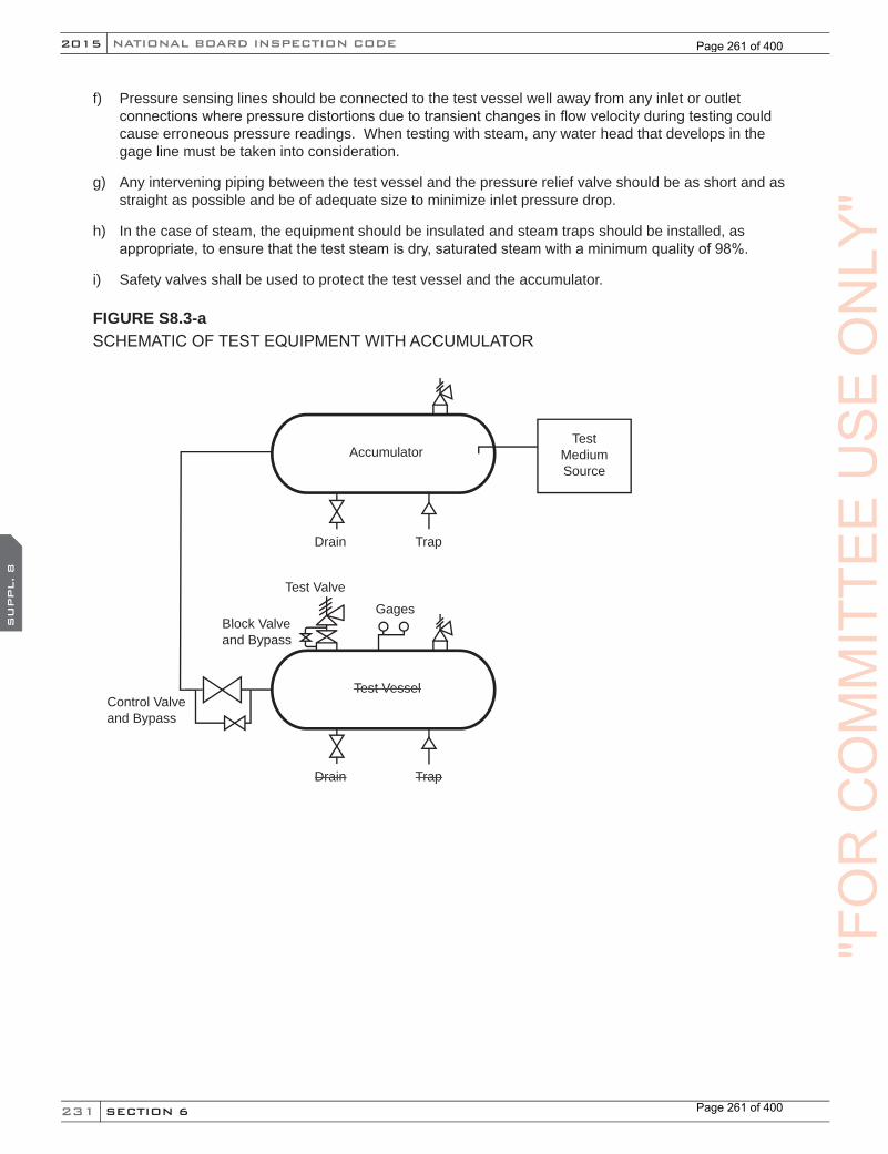
231
NATIONAL BOARD INSPECTION CODE2015
SECTION 6
SU
PPL. 8
f) Pressure sensing lines should be connected to the test vessel well away from any inlet or outlet connections where pressure distortions due to transient changes in flow velocity during testing could cause erroneous pressure readings. When testing with steam, any water head that develops in the gage line must be taken into consideration.
g) Any intervening piping between the test vessel and the pressure relief valve should be as short and as straight as possible and be of adequate size to minimize inlet pressure drop.
h) In the case of steam, the equipment should be insulated and steam traps should be installed, as appropriate, to ensure that the test steam is dry, saturated steam with a minimum quality of 98%.
i) Safety valves shall be used to protect the test vessel and the accumulator.
FIGURE S8.3-aSCHEMATIC OF TEST EQUIPMENT WITH ACCUMULATOR
Drain Trap
Accumulator
Test Vessel
TestMediumSource
GagesTest Valve
Drain Trap
Block Valveand Bypass
Control Valveand Bypass
"FO
RC
OM
MIT
TEE
US
EO
NLY
"
Page 261 of 400
Page 261 of 400
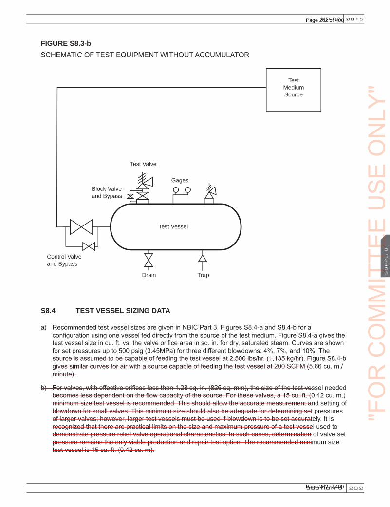
232
2015
SECTION 6
SU
PPL. 8
NB-23
FIGURE S8.3-bSCHEMATIC OF TEST EQUIPMENT WITHOUT ACCUMULATOR
Test Vessel
TestMediumSource
Gages
Test Valve
Drain Trap
Block Valveand Bypass
Control Valveand Bypass
S8.4 TEST VESSEL SIZING DATA
a) Recommended test vessel sizes are given in NBIC Part 3, Figures S8.4-a and S8.4-b for a configuration using one vessel fed directly from the source of the test medium. Figure S8.4-a gives the test vessel size in cu. ft. vs. the valve orifice area in sq. in. for dry, saturated steam. Curves are shown for set pressures up to 500 psig (3.45MPa) for three different blowdowns: 4%, 7%, and 10%. The source is assumed to be capable of feeding the test vessel at 2,500 lbs/hr. (1,135 kg/hr). Figure S8.4-b gives similar curves for air with a source capable of feeding the test vessel at 200 SCFM (5.66 cu. m./minute).
b) For valves, with effective orifices less than 1.28 sq. in. (826 sq. mm), the size of the test vessel needed becomes less dependent on the flow capacity of the source. For these valves, a 15 cu. ft. (0.42 cu. m.) minimum size test vessel is recommended. This should allow the accurate measurement and setting of blowdown for small valves. This minimum size should also be adequate for determining set pressures of larger valves; however, larger test vessels must be used if blowdown is to be set accurately. It is recognized that there are practical limits on the size and maximum pressure of a test vessel used to demonstrate pressure relief valve operational characteristics. In such cases, determination of valve set pressure remains the only viable production and repair test option. The recommended minimum size test vessel is 15 cu. ft. (0.42 cu. m).
"FO
RC
OM
MIT
TEE
CO
MM
ITTE
EC
OM
MIT
TEE
SU
PPL. 8
CO
MM
ITTE
ES
UPPL. 8
US
EO
NLY
"
Page 262 of 400
Page 262 of 400

233
NATIONAL BOARD INSPECTION CODE2015
SECTION 6
SU
PPL. 8
FIGURE S8.4-aRECOMMENDED TEST VESSEL SIZE, TEST MEDIUM: STEAM
300
250
200
150
100
50
00 5 10 15 20 25 30 35
Valve Flow Area (sq. in.)
Vess
el S
ize
(cu.
ft.)
•n
4% Blow
down
10% Blowdown7% Blowdown
t
n
•
t
Valve Flow Area (sq. cm)
32.3 64.5 96.7 129 161.3 193.5 225.8
– 8
– 7
– 6
– 5
– 4
– 3
– 2
– 1
Vess
el S
ize
(m3 )
FIGURE S8.4-bRECOMMENDED TEST VESSEL SIZE, TEST MEDIUM: AIR OR GAS
– 7
– 6
– 5
– 4
– 3
– 2
– 1
Valve Flow Area (sq. in.)
250
200
150
100
50
00 5 10 15 20 25 30 35
Vess
el S
ize
(cu.
ft.)
7% Blowdown
10% Blowdown
n
•
•n
Vess
el S
ize
(m3 )
Valve Flow Area (sq. cm)
32.3 64.5 96.7 129 161.3 193.5 225.8
"FO
RC
OM
MIT
TEE
US
EO
NLY
"
Page 263 of 400
Page 263 of 400

234
2015
SECTION 6
SU
PPL. 9
NB-23
SUPPLEMENT 9 PROCEDURES TO EXTEND THE “VR” CERTIFICATE OF AUTHORIZATION AND STAMP TO ASME “NV” STAMPED PRESSURE RELIEF DEVICES
S9.1 INTRODUCTION
Approval to extend the scope of the National Board “VR” Certificate of Authorization to the Certificate Holder to use the “VR” Stamp on ASME Code “NV” Class 1, 2, or 3 stamped pressure relief devices, which have been capacity certified by the National Board, may be given subject to the provisions that follow.
S9.2 ADMINISTRATIVE PROCEDURES
a) The repair organization shall hold a valid “VR” Certificate of Authorization.
b) The repair organization shall obtain a National Board “NR” Certificate of Authorization and stamp. The requirements for said certificate and stamp include, but are not limited to, the following. The repair organization shall:
1) Maintain a documented quality assurance program that meets the applicable requirements of NBIC Part 3, 1.8. This program shall also include all the applicable requirements for the use of the “VR” stamp;
2) Have a contract or agreement with an Inspection Agency to provide inspection of repaired “NV”-stamped pressure relief devices by Inspectors who have been qualified in accordance with the requirements of ASME QAI-1, Qualifications for Authorized Inspection;
3) Successfully complete a survey of the quality assurance program and its implementation. This survey shall be conducted by representatives of the National Board, the Jurisdiction wherein the applicant’s repair facilities are located, and the applicant’s Authorized Inspection Agency. Further verification of such implementation by the survey team may not be necessary if the applicant holds a valid ASME “NV” certificate and can verify by documentation the capability of implementing the quality assurance program for repair of “NV”-stamped pressure relief devices, covered by the applicant’s ASME “NV” certificate.
c) The application of the “NR” Certificate of Authorization and stamp shall clearly define the scope of intended activities with respect to the repair of Section III, “NV”-stamped pressure relief devices.
d) Revisions to the quality assurance program shall be acceptable to the Authorized Nuclear Inspector Supervisor and the National Board before being implemented.
e) The scope of the “VR” Certificate of Authorization shall include repair of “NV”-stamped pressure relief devices.
f) Verification testing of valves repaired by the applicant shall not be required provided such testing has been successfully completed under the applicant’s “VR” certification program.
g) A survey of the applicant for the “VR” Certificate of Authorization and endorsement of the repair of “NV”-stamped pressure relief devices may be made concurrently.
S9.3 GENERAL RULES
a) ASME Code Section III, “NV”-stamped pressure relief devices, which have been repaired in accordance with these rules, shall be stamped with both the “VR” and “NR” stamps.
b) The “VR” and “NR” stamps shall be applied only to “NV” stamped (Class 1, 2, or 3) National Board capacity certified pressure relief devices that have been disassembled, inspected, and repaired as
"FO
RC
OM
MIT
TEE
CO
MM
ITTE
EC
OM
MIT
TEE
SU
PPL. 9
CO
MM
ITTE
ES
UPPL. 9
US
EO
NLY
"
Page 264 of 400
Page 264 of 400

235
NATIONAL BOARD INSPECTION CODE2015
SECTION 6
SU
PPL. 9
necessary, such that the valves’ condition and performance are equivalent to the standards for new valves.
c) All measuring and test equipment used in the repair of pressure relief devices shall be calibrated against certified equipment having known valid relationships to nationally recognized standards.
d) Documentation of the repair of “NV”-stamped pressure relief devices shall be recorded on the National Board Form NVR-1, Report of Repair/ Replacement Activities for Nuclear Pressure Relief Devices, in accordance with the requirements of NBIC Part 3, 1.8.
e) When an ASME “NV”-stamped pressure relief device requires a duplicate nameplate because the original nameplate is illegible or missing, it may be applied using the procedures of NBIC Part 3, 5.12.5 provided concurrence is obtained from the Authorized Nuclear Inspector and Jurisdiction. In this case the nameplate shall be marked “SEC. III” to indicate original ASME Code stamping.
"FO
RC
OM
MIT
TEE
US
EO
NLY
"
Page 265 of 400
Page 265 of 400
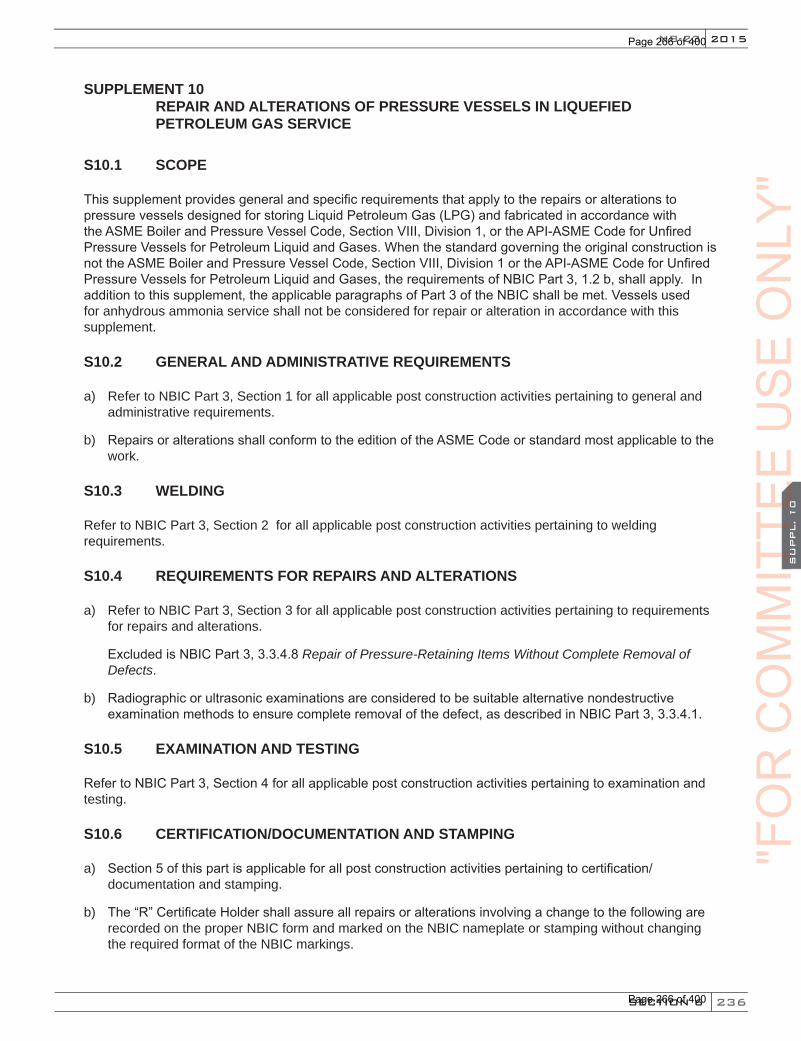
236
2015
SECTION 6
SU
PPL. 10
NB-23
SUPPLEMENT 10REPAIR AND ALTERATIONS OF PRESSURE VESSELS IN LIQUEFIED PETROLEUM GAS SERVICE
S10.1 SCOPE
This supplement provides general and specific requirements that apply to the repairs or alterations to pressure vessels designed for storing Liquid Petroleum Gas (LPG) and fabricated in accordance with the ASME Boiler and Pressure Vessel Code, Section VIII, Division 1, or the API-ASME Code for Unfired Pressure Vessels for Petroleum Liquid and Gases. When the standard governing the original construction is not the ASME Boiler and Pressure Vessel Code, Section VIII, Division 1 or the API-ASME Code for Unfired Pressure Vessels for Petroleum Liquid and Gases, the requirements of NBIC Part 3, 1.2 b, shall apply. In addition to this supplement, the applicable paragraphs of Part 3 of the NBIC shall be met. Vessels used for anhydrous ammonia service shall not be considered for repair or alteration in accordance with this supplement.
S10.2 GENERAL AND ADMINISTRATIVE REQUIREMENTS
a) Refer to NBIC Part 3, Section 1 for all applicable post construction activities pertaining to general and administrative requirements.
b) Repairs or alterations shall conform to the edition of the ASME Code or standard most applicable to the work.
S10.3 WELDING
Refer to NBIC Part 3, Section 2 for all applicable post construction activities pertaining to welding requirements.
S10.4 REQUIREMENTS FOR REPAIRS AND ALTERATIONS
a) Refer to NBIC Part 3, Section 3 for all applicable post construction activities pertaining to requirements for repairs and alterations.
Excluded is NBIC Part 3, 3.3.4.8 Repair of Pressure-Retaining Items Without Complete Removal of Defects.
b) Radiographic or ultrasonic examinations are considered to be suitable alternative nondestructive examination methods to ensure complete removal of the defect, as described in NBIC Part 3, 3.3.4.1.
S10.5 EXAMINATION AND TESTING
Refer to NBIC Part 3, Section 4 for all applicable post construction activities pertaining to examination and testing.
S10.6 CERTIFICATION/DOCUMENTATION AND STAMPING
a) Section 5 of this part is applicable for all post construction activities pertaining to certification/documentation and stamping.
b) The “R” Certificate Holder shall assure all repairs or alterations involving a change to the following are recorded on the proper NBIC form and marked on the NBIC nameplate or stamping without changing the required format of the NBIC markings.
"FO
RC
OM
MIT
TEE
CO
MM
ITTE
EC
OM
MIT
TEE
SU
PPL. 10
CO
MM
ITTE
ES
UPPL. 10
US
EO
NLY
"
Page 266 of 400
Page 266 of 400
237
NATIONAL BOARD INSPECTION CODE2015
SECTION 6
SU
PPL. 10
1) Service for which the container is designed (for example, underground, aboveground, or both).
2) Dip tube length.
3) Maximum filling limit with liquid temperature reference.
S10.7 INSPECTION
Refer to NBIC Part 2, Supplement 7 for all applicable post construction activities pertaining to inspection.
S10.8 COATINGS
When coatings are reapplied, the user should verify the coating is compatible with any coating that remains intact and is suited for the intended service application.
"FO
RC
OM
MIT
TEE
US
EO
NLY
"
Page 267 of 400
Page 267 of 400
238
2015
SECTION 7
NB-23
SEC
TIO
N 7
PART 3, SECTION 7 REPAIRS AND ALTERATIONS — NBIC POLICY FOR METRICATION
7.1 GENERAL
This policy provides guidance for the use of US customary units and metric units. Throughout the NBIC, metric units are identified and placed in parentheses after the US customary units referenced in the text and associated tables. For each repair or alteration performed, selection of units shall be based on the units used in the original code of construction. For example, items constructed using US customary units shall be repaired or altered using US customary units. The same example applies to items constructed using metric units. Whichever units are selected, those units are to be used consistently throughout each repair or alter-ation. Consistent use of units includes all aspects of work required for repairs or alterations (i.e. materials, design, procedures, testing, documentation, and stamping, etc.).
7.2 EQUIVALENT RATIONALE
The rationale taken to convert metric units and US customary units involves knowing the difference be-tween a soft conversion and a hard conversion. A soft conversion is an exact conversion. A hard conversion is simply performing a soft conversion and then rounding off within a range of intended precision. When values specified in the NBIC are intended to be approximate values, a hard conversion is provided. If an exact value is needed to maintain safety or required based on using good engineering judgment, then a soft conversion will be used. In general, approximate accuracy is acceptable for most repairs or alterations per-formed using the requirements of the NBIC. Therefore, within the NBIC, metric equivalent units are primarily hard conversions.
The following examples are provided for further clarification and understanding of soft conversions versus hard conversions:
Example 1: Using 1 in. = 25.4 mm;12 in. = 304.8 mm (soft conversion)
Example 2: Using the above conversion, a hard conversion may be 300 mm or 305 mm depending on the degree of precision needed.
7.3 PROCEDURE FOR CONVERSION
The following guidelines shall be used to convert between US customary units and metric units within the text of the NBIC:
a) All US customary units will be converted using a soft conversion;
b) Soft conversion calculations will be reviewed for accuracy;
c) Based on specified value in the NBIC, an appropriate degree of precision shall be identified;
d) Once the degree of precision is decided, rounding up or down may be applied to each soft conversion in order to obtain a hard conversion; and
e) Use of hard conversion units shall be used consistently throughout the NBIC wherever soft conversions are not required.
Note: Care shall be taken to minimize percentage difference between units.
"FO
RC
OM
MIT
TEE
CO
MM
ITTE
EC
OM
MIT
TEE
SEC
TIO
N 7
CO
MM
ITTE
ES
EC
TIO
N 7
US
EO
NLY
"
Page 268 of 400
Page 268 of 400
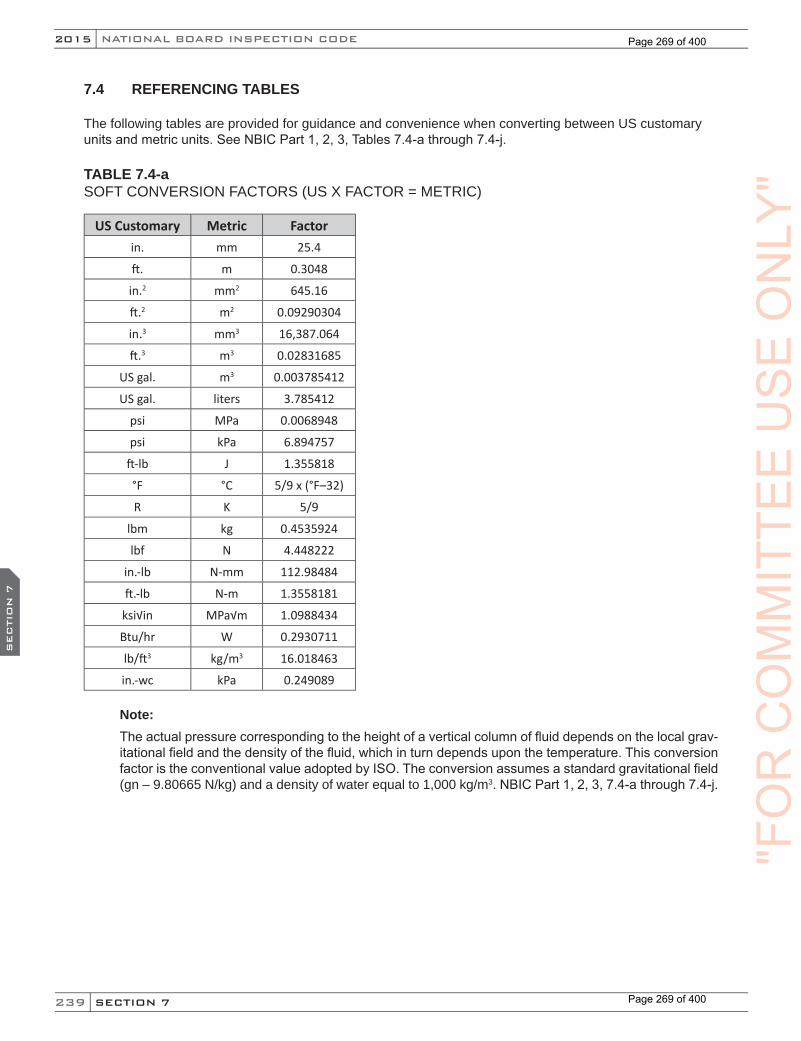
239
NATIONAL BOARD INSPECTION CODE2015
SECTION 7
SEC
TIO
N 7
7.4 REFERENCING TABLES
The following tables are provided for guidance and convenience when converting between US customary units and metric units. See NBIC Part 1, 2, 3, Tables 7.4-a through 7.4-j.
TABLE 7.4-aSOFT CONVERSION FACTORS (US X FACTOR = METRIC)
US Customary Metric Factorin. mm 25.4
ft. m 0.3048
in.2 mm2 645.16
ft.2 m2 0.09290304
in.3 mm3 16,387.064
ft.3 m3 0.02831685
US gal. m3 0.003785412
US gal. liters 3.785412
psi MPa 0.0068948
psi kPa 6.894757
ft-lb J 1.355818
°F °C 5/9 x (°F–32)
R K 5/9
lbm kg 0.4535924
lbf N 4.448222
in.-lb N-mm 112.98484
ft.-lb N-m 1.3558181
ksi√in MPa√m 1.0988434
Btu/hr W 0.2930711
lb/ft3 kg/m3 16.018463
in.-wc kPa 0.249089
Note:The actual pressure corresponding to the height of a vertical column of fluid depends on the local grav-itational field and the density of the fluid, which in turn depends upon the temperature. This conversion factor is the conventional value adopted by ISO. The conversion assumes a standard gravitational field (gn – 9.80665 N/kg) and a density of water equal to 1,000 kg/m3. NBIC Part 1, 2, 3, 7.4-a through 7.4-j.
"FO
RC
OM
MIT
TEE
US
EO
NLY
"
Page 269 of 400
Page 269 of 400

240
2015
SECTION 7
NB-23
SEC
TIO
N 7
Temperature shall be converted to within 1°C as shown in NBIC Part 1, 2, 3, Table 7.4-b.
TABLE 7.4-bTEMPERATURE EQUIVALENTS
Temperature °F Temperature °C60 16
70 21
100 38
120 49
350 177
400 204
450 232
800 427
1,150 621
Fractions of an inch shall be converted according to NBIC Part 1, 2, 3, Table 7.4-c. Even increments of inch-es are in even multiples of 25 mm. For example, 40 inches is equivalent to 1,000 mm. Intermediate values may be interpolated rather than converting and rounding to the nearest mm.
TABLE 7.4-c US FRACTIONS/METRIC EQUIVALENTS
Inches Millimeters1/32 0.8
3/64 1.2
1/16 1.5
3/32 2.5
1/8 3
5/32 4
3/16 5
7/32 5.5
1/4 6
5/16 8
3/8 10
7/16 11
1/2 13
9/16 14
5/8 16
11/16 17
3/4 19
7/8 22
1 25
"FO
RC
OM
MIT
TEE
CO
MM
ITTE
EC
OM
MIT
TEE
SEC
TIO
N 7
CO
MM
ITTE
ES
EC
TIO
N 7
US
EO
NLY
"
Page 270 of 400
Page 270 of 400
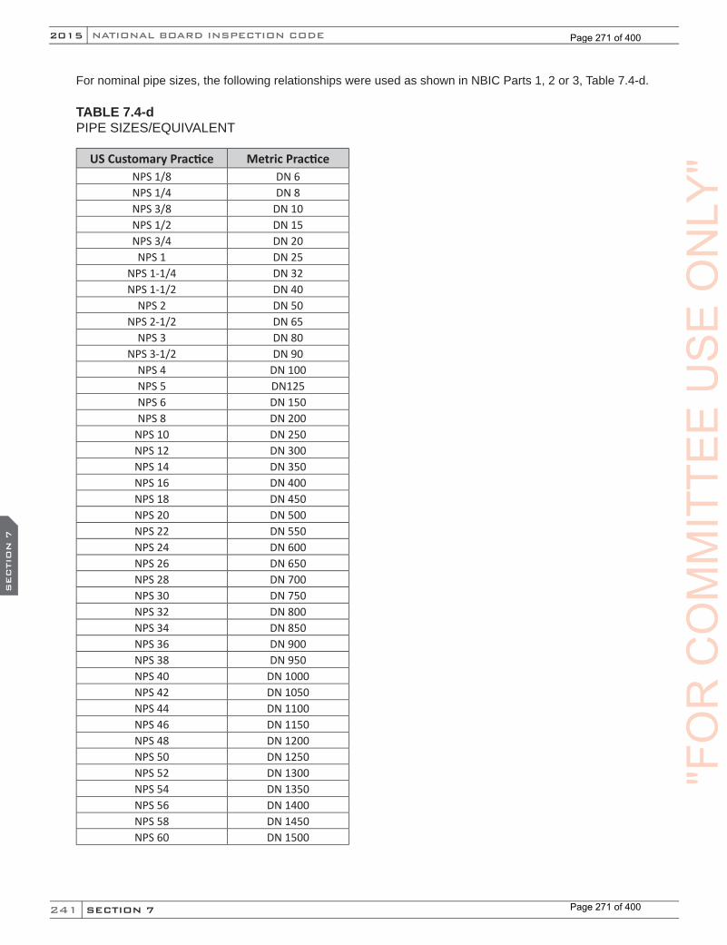
241
NATIONAL BOARD INSPECTION CODE2015
SECTION 7
SEC
TIO
N 7
For nominal pipe sizes, the following relationships were used as shown in NBIC Parts 1, 2 or 3, Table 7.4-d.
TABLE 7.4-dPIPE SIZES/EQUIVALENT
US Customary Practice Metric PracticeNPS 1/8 DN 6NPS 1/4 DN 8NPS 3/8 DN 10NPS 1/2 DN 15NPS 3/4 DN 20NPS 1 DN 25
NPS 1-1/4 DN 32NPS 1-1/2 DN 40
NPS 2 DN 50NPS 2-1/2 DN 65
NPS 3 DN 80NPS 3-1/2 DN 90
NPS 4 DN 100NPS 5 DN125NPS 6 DN 150NPS 8 DN 200
NPS 10 DN 250NPS 12 DN 300NPS 14 DN 350NPS 16 DN 400NPS 18 DN 450NPS 20 DN 500NPS 22 DN 550NPS 24 DN 600NPS 26 DN 650NPS 28 DN 700NPS 30 DN 750NPS 32 DN 800NPS 34 DN 850NPS 36 DN 900NPS 38 DN 950NPS 40 DN 1000NPS 42 DN 1050NPS 44 DN 1100NPS 46 DN 1150NPS 48 DN 1200NPS 50 DN 1250NPS 52 DN 1300NPS 54 DN 1350NPS 56 DN 1400NPS 58 DN 1450NPS 60 DN 1500
"FO
RC
OM
MIT
TEE
US
EO
NLY
"
Page 271 of 400
Page 271 of 400
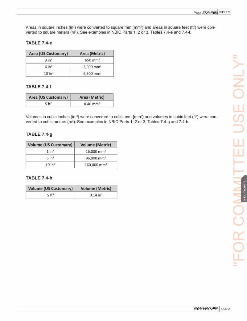
242
2015
SECTION 7
NB-23
SEC
TIO
N 7
Areas in square inches (in2) were converted to square mm (mm2) and areas in square feet (ft2) were con-verted to square meters (m2). See examples in NBIC Parts 1, 2 or 3, Tables 7.4-e and 7.4-f.
TABLE 7.4-e
Area (US Customary) Area (Metric)3 in2 650 mm2
6 in2 3,900 mm2
10 in2 6,500 mm2
TABLE 7.4-f
Area (US Customary) Area (Metric)5 ft2 0.46 mm2
Volumes in cubic inches (in.3) were converted to cubic mm (mm3) and volumes in cubic feet (ft3) were con-verted to cubic meters (m3). See examples in NBIC Parts 1, 2 or 3, Tables 7.4-g and 7.4-h.
TABLE 7.4-g
Volume (US Customary) Volume (Metric)1 in3 16,000 mm3
6 in3 96,000 mm3
10 in3 160,000 mm3
TABLE 7.4-h
Volume (US Customary) Volume (Metric)5 ft3 0.14 m3
"FO
RC
OM
MIT
TEE
CO
MM
ITTE
EC
OM
MIT
TEE
SEC
TIO
N 7
CO
MM
ITTE
ES
EC
TIO
N 7
US
EO
NLY
"
Page 272 of 400
Page 272 of 400
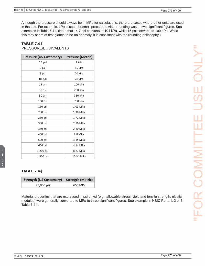
243
NATIONAL BOARD INSPECTION CODE2015
SECTION 7
SEC
TIO
N 7
Although the pressure should always be in MPa for calculations, there are cases where other units are used in the text. For example, kPa is used for small pressures. Also, rounding was to two significant figures. See examples in Table 7.4-i. (Note that 14.7 psi converts to 101 kPa, while 15 psi converts to 100 kPa. While this may seem at first glance to be an anomaly, it is consistent with the rounding philosophy.)
TABLE 7.4-iPRESSURE/EQUIVALENTS
Pressure (US Customary) Pressure (Metric)0.5 psi 3 kPa
2 psi 15 kPa
3 psi 20 kPa
10 psi 70 kPa
15 psi 100 kPa
30 psi 200 kPa
50 psi 350 kPa
100 psi 700 kPa
150 psi 1.03 MPa
200 psi 1.38 MPa
250 psi 1.72 MPa
300 psi 2.10 MPa
350 psi 2.40 MPa
400 psi 2.8 MPa
500 psi 3.45 MPa
600 psi 4.14 MPa
1,200 psi 8.27 MPa
1,500 psi 10.34 MPa
TABLE 7.4-j
Strength (US Customary) Strength (Metric)95,000 psi 655 MPa
Material properties that are expressed in psi or ksi (e.g., allowable stress, yield and tensile strength, elastic modulus) were generally converted to MPa to three significant figures. See example in NBIC Parts 1, 2 or 3, Table 7.4-h.
"FO
RC
OM
MIT
TEE
US
EO
NLY
"
Page 273 of 400
Page 273 of 400

244
2015
SECTION 8
SEC
TIO
N 8
NB-23
PART 3, SECTION 8 REPAIRS AND ALTERATIONS — PREPARATION OF TECHNICAL
INQUIRIES TO THE NATIONAL BOARD INSPECTION CODE COMMITTEE
8.1 INTRODUCTION
The NBIC Committee meets regularly to consider written requests for interpretations and revisions to the code rules. This section provides guidance to code users for submitting technical inquiries to the Committee. Technical inquires include requests for additions to the code rules and requests for code Interpretations, as described below.
a) Code Revisions Code revisions are considered to accommodate technological developments, address administrative requirements, or to clarify code intent.
b) Code Interpretations Code Interpretations provide clarification of the meaning of existing rules in the code, and are also pre-sented in question and reply format. Interpretations do not introduce new requirements. In cases where existing code text does not fully convey the meaning that was intended, and revision of the rules is required to support an Interpretation, an intent Interpretation will be issued and the code will be revised. As a matter of published policy, the National Board does not approve, certify, or endorse any item, construction, propriety device or activity and, accordingly, inquiries requiring such consideration will be returned. Moreover, the National Board does not act as a consultant on specific engineering problems or on the general application or understanding of the code rules.Inquiries that do not comply with the provisions of this section or that do not provide sufficient information for the Committee’s full understanding may result in the request being returned to the inquirer with no action.
8.2 INQUIRY FORMAT
Inquiries submitted to the Committee shall include:
a) Purpose Specify one of the following:
1) Revision of present code rules;
2) New or additional code rules; or
3) code Interpretation.
b) Background Provide concisely the information needed for the Committee’s understanding of the inquiry, being sure to include reference to the applicable Code Edition, Addenda, paragraphs, figures, and tables. Provide a copy of the specific referenced portions of the code.
c) Presentations The inquirer may attend a meeting of the Committee to make a formal presentation or to answer ques-tions from the Committee members with regard to the inquiry. Attendance at a Committee meeting shall be at the expense of the inquirer. The inquirer’s attendance or lack of attendance at a meeting shall not be a basis for acceptance or rejection of the inquiry by the Committee.
"FO
RC
OM
MIT
TEE
CO
MM
ITTE
EC
OM
MIT
TEE
SEC
TIO
N 8
CO
MM
ITTE
ES
EC
TIO
N 8
US
EO
NLY
"
Page 274 of 400
Page 274 of 400

245
NATIONAL BOARD INSPECTION CODE2015
SECTION 8
SEC
TIO
N 8
8.3 CODE REVISIONS OR ADDITIONS
Request for code revisions or additions shall provide the following:
a) Proposed Revisions or Additions For revisions, identify the rules of the code that require revision and submit a copy of the appropriate rules as they appear in the code, marked up with the proposed revision. For additions, provide the rec-ommended wording referenced to the existing code rules.
b) Statement of Need Provide a brief explanation of the need for the revision or addition.
c) Background Information Provide background information to support the revision or addition, including any data or changes in technology that form the basis for the request that will allow the Committee to adequately evaluate the proposed revision or addition. Sketches, tables, figures, and graphs should be submitted as appropri-ate. When applicable, identify any pertinent paragraph in the code that would be affected by the revision or addition and identify paragraphs in the code that reference the paragraphs that are to be revised or added.
8.4 CODE INTERPRETATIONS
Requests for code Interpretations shall provide the following:
a) InquiryProvide a condensed and precise question, omitting superfluous background information and, when possible, composed in such a way that a “yes” or a “no” reply, with brief provisos if needed, is accept-able. The question should be technically and editorially correct.
b) Reply Provide a proposed reply that will clearly and concisely answer the inquiry question. Preferably the reply should be “yes” or “no” with brief provisos, if needed.
c) Background Information Provide any background information that will assist the committee in understanding the proposed In-quiry and Reply Requests for Code Interpretations must be limited to an interpretation of the particular requirement in the code. The Committee cannot consider consulting type requests such as:
1) A review of calculations, design drawings, welding qualifications, or descriptions of equipment or Parts to determine compliance with code requirements;
2) A request for assistance in performing any code-prescribed functions relating to, but not limited to, material selection, designs, calculations, fabrication, inspection, pressure testing, or installation;
3) A request seeking the rationale for code requirements.
8.5 SUBMITTALS
Submittals to and responses from the Committee shall meet the following criteria:
a) SubmittalInquiries from code users shall be in English and preferably be submitted in typewritten form; however, legible handwritten inquiries will be considered. They shall include the name, address, telephone num-ber, fax number, and email address, if available, of the inquirer and be mailed to the following address:
"FO
RC
OM
MIT
TEE
US
EO
NLY
"
Page 275 of 400
Page 275 of 400
246
2015
SECTION 8
SEC
TIO
N 8
NB-23
Secretary, NBIC Committee The National Board of Boiler and Pressure Vessel Inspectors 1055 Crupper AvenueColumbus, OH 43229
As an alternative, inquiries may be submitted via fax or email to:Secretary NBIC Committee Fax: 614.847.1828Email: [email protected]
b) Response The Secretary of the NBIC Committee shall acknowledge receipt of each properly prepared inquiry and shall provide a written response to the inquirer upon completion of the requested action by the NBIC Committee.
"FO
RC
OM
MIT
TEE
CO
MM
ITTE
EC
OM
MIT
TEE
SEC
TIO
N 8
CO
MM
ITTE
ES
EC
TIO
N 8
US
EO
NLY
"
Page 276 of 400
Page 276 of 400

247
NATIONAL BOARD INSPECTION CODE2015
SECTION 9
SEC
TIO
N 9
PART 3, SECTION 9 REPAIRS AND ALTERATIONS — GLOSSARY OF TERMS
9.1 DEFINITIONS
For the purpose of applying the rules of the NBIC, the following terms and definitions shall be used herein as applicable to each part:
Additional terms and definitions specific to DOT Transport Tanks are defined in NBIC Part 2, Supplement 6.
Accumulator — A vessel in which the test medium is stored or accumulated prior to its use for testing.
Alteration — A change in the item described on the original Manufacturer’s Data Report which affects the pressure containing capability of the pressure-retaining item. (See NBIC Part 3, 3.4.3, Examples of Alteration)Nonphysical changes such as an increase in the maximum allowable working pressure (internal or external), increase in design temperature, or a reduction in minimum temperature of a pressure-retaining item shall be considered an alteration.
ANSI — The American National Standards Institute.
Appliance — A piece of equipment that includes all controls, safety devices, piping, fittings, and vessel(s) within a common frame or enclosure that is listed and labeled by a nationally recognized testing agency for its intended use.
ASME — The American Society of Mechanical Engineers.
ASME Code — The American Society of Mechanical Engineers Boiler and Pressure Vessel Code published by that Society, including addenda and Code Cases, approved by the associated ASME Board.
Assembler — An organization who purchases or receives from a manufacturer the necessary component parts of valves and assembles, adjusts, tests, seals, and ships safety or safety relief valves at a geographical location, and using facilities other than those used by the manufacturer.
Authorized Inspection Agency (AIA)Inservice: An Authorized Inspection Agency is either:a) a jurisdictional authority as defined in the National Board Constitution; or
b) an entity that is accredited by the National Board meeting NB-369, Accreditation of Authorized Inspection Agencies Performing Inservice Inspection Activities; NB-371, Accreditation of Owner-User Inspection Organizations (OUIO); or NB-390, Qualifications and duties for Federal Inspection Agencies (FIAs) Performing Inservice Inspection Activities.
New Construction: An Authorized Inspection Agency is one that is accredited by the National Board meeting the qualification and duties of NB-360, Criteria for Acceptance of Authorized Inspection Agencies for New Construction.
Biomass — Fuels which result from biological sources requiring a relatively short time for replenishment: Wood and bagasse are typical examples. Biomass Fired Boiler — A boiler which fires biomass as its primary fuel.Capacity Certification — The verification by the National Board that a particular valve design or model has successfully completed all capacity testing as required by the ASME Code.
(15) "FO
R(15) "F
OR
(15)
CO
MM
ITTE
EU
SE
ON
LY"
Page 277 of 400
Page 277 of 400
248
2015
SECTION 9
SEC
TIO
N 9
NB-23
Boiler — A boiler is a closed vessel in which water or other liquid is heated, steam or vapor generated, steam or vapor is superheated, or any combination thereof, under pressure for use external to itself, by the direct application of energy from the combustion of fuels or from electricity or solar energy. The term boiler also shall include the apparatus used to generate heat and all controls and safety devices associated with such apparatus or the closed vessel.
High-Temperature Water Boiler — A power boiler in which water is heated and operates at a pressure in excess of 160 psig (1.1 MPa) and/or temperature in excess of 250°F (121°C).
Hot-Water Heating Boiler — A hot water boiler installed to operate at pressures not exceeding 160 psig (1,100 kPa) and/or temperatures not exceeding 250°F (121°C), at or near the boiler outlet.
Hot-Water Supply Boiler — A boiler that furnishes hot water to be used externally to itself at a pressure less than or equal to 160 psig (1,100 kPa gage) or a temperature less than or equal to 250°F (120°C) at or near the boiler outlet
Power Boiler — A boiler in which steam or other vapor is generated at a pressure in excess of 15 psig (100 kPa) for use external to itself. The term power boiler includes fired units for vaporizing liquids other than water, but does not include fired process heaters and systems. (See also High-Temperature Water Boiler).
Steam Heating Boiler — A steam boiler installed to operate at pressures not exceeding 15 psig (100 kPa).
Carbons Recycle — See Flyash Recycle.Chimney or Stack — A device or means for providing the venting or escape of combustion gases from the operating unit.
Confined Space –– Work locations considered “confined” because their configurations hinder the activities of employees who must enter, work in and exit them. A confined space has limited or restricted means for entry or exit, and it is not designed for continuous employee occupancy. Confined spaces include, but are not limited to, underground vaults, tanks, storage bins, manholes, pits, silos, process vessels, and pipelines. Regulatory Organizations often use the term “permit-required confined space” (permit space) to describe a confined space that has one or more of the following characteristics: contains or has the potential to contain a hazardous atmosphere; contains a material that has the potential to engulf an entrant; has walls that converge inward or floors that slope downward and taper into a smaller area which could trap or asphyxiate an entrant; or contains any other recognized safety or health hazard, such as unguarded machinery, exposed live wires, or heat stress. Confined space entry requirements may differ in many locations and the Inspector is cautioned of the need to comply with local or site- specific confined space entry requirements.
Conversion
Pressure Relief Devices –– The change of a pressure relief valve from one capacity-certified configuration to another by use of manufacturer’s instructions.
Units of Measure –– Changing the numeric value of a parameter from one system of units to another.
Conveyor System(s) — A fuel transport system utilized on biomass boilers that drops fuel onto a movingbelt, bucket elevator, drag link conveyor, or a screw or auger mechanism. (The speed of the conveyor may be varied to meet fuel demand.)
Demonstration — A program of making evident by illustration, explanation, and completion of tasks documenting evaluation of an applicant’s ability to perform code activities, including the adequacy of the applicant’s quality program, and by a review of the implementation of that program at the address of record and/or work location.
(15)"F
OR
"FO
R"F
OR
SEC
TIO
N 9
"FO
RS
EC
TIO
N 9
CO
MM
ITTE
EU
SE
ON
LY"
Page 278 of 400
Page 278 of 400

249
NATIONAL BOARD INSPECTION CODE2015
SECTION 9
SEC
TIO
N 9
Dense Phase Pneumatic System(s) — A batch feed transport system used on solid fuel fired boilers for both fuel delivery and/or ash removal. In this system the material to be transported is dropped through a valve in a pressure vessel. When the vessel is filled the valve closes and air at a pressure from 30 to 100 psig (200 to 700 kPa) is admitted and the material leaves the vessel in the form of a “slug”. The sequence then repeats.
Dutchman — Generally limited to tube or pipe cross-section replacement. The work necessary to remove a compromised section of material and replace the section with material meeting the service requirements and installation procedures acceptable to the Inspector. Also recognized as piecing.
Emissions — The discharge of various Federal or State defined air pollutants into the surrounding atmosphere during a given time period.Emissions Control System — An arrangement of devices, usually in series, used to capture various air pollutants and thereby reduce the amount of these materials, or gases, being admitted to the surrounding atmosphere, below Federal or State defined standards. Examination — In process work denoting the act of performing or completing a task of interrogation of compliance. Visual observations, radiography, liquid penetrant, magnetic particle, and ultrasonic methods are recognized examples of examination techniques.
Exit — A doorway, hallway, or similar passage that will allow free, normally upright unencumbered egress from an area.
Field — A temporary location, under the control of the Certificate Holder, that is used for repairs and/or alterations to pressure-retaining items at an address different from that shown on the Certificate Holder’s Certificate of Authorization
Fluidized Bed — A process in which a bed of granulated particles are maintained in a mobile suspension by an upward flow of air or gas.
Fluidized Bed (Bubbling) — A fluidized bed in which the fluidizing velocity is less than the terminal velocity of individual bed particles where part of the fluidizing gas passes through as bubbles.
Fluidized Bed (Circulating) — A fluidized bed in which the fluidizing velocities exceed the terminal velocity of the individual bed particles.
Flyash — Suspended ash particles carried in the flue gas.
Flyash Collector — A device designed to remove flyash in the dry form from the flue gas.
Flyash Recycle — The reintroduction of flyash/unburned carbon from the flyash collector into the combustion zone, in order to complete the combustion of unburned fuel, thereby improving efficiency.
Forced-Flow Steam Generator — A steam generator with no fixed steamline and waterline.
Fuel Transport Fan — A fan which generates airflow capable of moving fuel particles, in suspension, from a metering device to the combustion zone.
Grate — The surface on which fuel is supported and burned and through which air is passed for combustion.
Hydrostatic Test — A liquid pressure test which is conducted using water as the test medium.
Inspection — A process of review to ensure engineering design, materials, assembly, examination, and testing requirements have been met and are compliant with the code.
Induced Draft Fan — A fan exhausting hot gases from the heat absorbing equipment.Inspector — See National Board Commissioned Inspector and National Board Owner-User Commissioned Inspector.
(15)
"FO
RC
OM
MIT
TEE
US
EO
NLY
"
Page 279 of 400
Page 279 of 400
250
2015
SECTION 9
SEC
TIO
N 9
NB-23
Intervening — Coming between or inserted between, as between the test vessel and the valve being tested.
Jurisdiction — A governmental entity with the power, right, or authority to interpret and enforce law, rules, or ordinances pertaining to boilers, pressure vessels, or other pressure-retaining items. It includes National Board member jurisdictions defined as “jurisdictional authorities.”
Jurisdictional Authority — A member of the National Board, as defined in the National Board Constitution.
Lean Phase Pneumatic System(s) — A fuel transport system utilized on biomass boilers that drops fuel intoa moving airstream, mixes with the air, and travels through a pipe at a velocity in the region of 5,000 ft/min (1,525 m/min). Air pressures are in the region of 25 inches (635 mm) water column.
Lift Assist Device — A device used to apply an auxiliary load to a pressure relief valve stem or spindle, used to determine the valve set pressure as an alternative to a full pressure test.
Liquid Pressure Test — A pressure test using water or other incompressible fluid as a test medium.
Manufacturer’s Documentation — The documentation that includes technical information and certification required by the original code of construction.
Mechanical Assembly — The work necessary to establish or restore a pressure retaining boundary, under supplementary materials, whereby pressure-retaining capability is established through a mechanical, chemical, or physical interface, as defined under the rules of the NBIC.
Mechanical Repair Method — A method of repair, which restores a pressure retaining boundary to a safe and satisfactory operating condition, where the pressure retaining boundary is established by a method other than welding or brazing, as defined under the rules of the NBIC.Metering Device — A method of controlling the amount of fuel, or air, flowing into the combustion zone. “NR” Certificate Holder — An organization in possession of a valid “NR” Certificate of Authorization issued by the National Board.
National Board — The National Board of Boiler and Pressure Vessel Inspectors.
National Board Commissioned Inspector — An individual who holds a valid and current National Board Commission.
NBIC — The National Board Inspection Code published by The National Board of Boiler and Pressure Vessel Inspectors.
Nuclear Items — Items constructed in accordance with recognized standards to be used in nuclear power plants or fuel processing facilities.
Original Code of Construction — Documents promulgated by recognized national standards writing bodies that contain technical requirements for construction of pressure-retaining items or equivalent to which the pressure-retaining item was certified by the original manufacturer.Overfire Air — Air admitted to the furnace above the grate surface /fuel bed. Used to complete the combustion of fine particles, in suspension. Also aids in reducing NOx formation. Owner or User — As referenced in lower case letters means any person, firm, or corporation legally responsible for the safe operation of any pressure-retaining item.
Owner-User Inspection Organization — An owner or user of pressure-retaining items that maintains an established inspection program, whose organization and inspection procedures meet the requirements of the National Board rules and are acceptable to the jurisdiction or jurisdictional authority wherein the owner or user is located.
Owner-User Inspector — An individual who holds a valid and current National Board Owner-User Commission.
(15)
"FO
R"F
OR
"FO
RS
EC
TIO
N 9
"FO
RS
EC
TIO
N 9
CO
MM
ITTE
EU
SE
ON
LY"
Page 280 of 400
Page 280 of 400
251
NATIONAL BOARD INSPECTION CODE2015
SECTION 9
SEC
TIO
N 9
Piecing — A repair method used to remove and replace a portion of piping or tubing material with a suitable material and installation procedure.
Pneumatic Test — A pressure test which uses air or another compressible gas as the test medium.
Potable Water Heaters — A corrosion resistant appliance that includes the controls and safety devices to supply potable hot water at pressure not exceeding 160 psig (1,100 kPa) and temperature not in excess of 210°F (99°C).
Fired Storage Water Heater — A potable water heater in which water is heated by electricity, the combustion of solid, liquid, or gaseous fuels and stores water within the same appliance.
Indirect Fired Water Heater — A potable water heater in which water is heated by an internal coil or heat exchanger that receives its heat from an external source. Indirect fired water heaters provide water directly to the system or store water within the same appliance.
Circulating Water Heater — A potable water heater which furnishes water directly to the system or to a separate storage tank. Circulating water heaters may be either natural or forced flow.
Pressure-Retaining Items (PRI) — Any boiler, pressure vessel, piping, or material used for the containment of pressure, either internal or external. The pressure may be obtained from an external source, or by the application of heat from a direct source, or any combination thereof.
Pressure Test — A test that is conducted using a fluid (liquid or gas) contained inside a pressure-retaining item.Pressure Vessel — A pressure vessel is a container other than a boiler or piping used for the containment of pressure.“R” Certificate Holder — An organization in possession of a valid “R” Certificate of Authorization issued by the National Board.
Re-ending — A method used to join original code of construction piping or tubing with replacement piping or tubing material for the purpose of restoring a required dimension, configuration or pressure-retaining capacity.
Repair — The work necessary to restore pressure-retaining items to a safe and satisfactory operating condition.
Re-rating — See alteration.
Safe Point of Discharge — A location that will not cause property damage, equipment damage, or create a health or safety threat to personnel in the event of discharge.
Safety Relief Valves — A safety relief valve is a pressure relief valve characterized by rapid opening or pop action, or by opening in proportion to the increase in pressure over the opening pressure, depending on application.
Seal Weld — Any weld designed primarily to provide a specific degree of tightness against leakage. A seal weld is not intended to provide structural integrity to a pressure retaining item.
Settings — Those components and accessories required to provide support for the component during operation and during any related maintenance activity.
Shop — A permanent location, the address that is shown on the Certificate of Authorization, from which a Certificate Holder controls the repair and/or alteration of pressure-retaining items.
(15)"F
OR(15)
"FO
R(15)C
OM
MIT
TEE
US
EO
NLY
"
Page 281 of 400
Page 281 of 400

252
2015
SECTION 9
SEC
TIO
N 9
NB-23
Suspension Burner — A combustion system in which the fuel is in the form of relatively small particles, Their buoyancy is maintained in the transport airstream and the fuel/air mixture flow stream, until combustion is completed.Testing Laboratory — National Board accepted laboratory that performs functional and capacity tests of pressure relief devices.
Thermal Fluid Heater — A thermal fluid heater is a closed vessel in which a fluid other than water is heated by the direct application of heat from a thermal energy source. Depending on the process heating requirements, the fluid may be vaporized with normal circulation but, more often, the fluid is heated and circulated by a pump.
Transient — An occurrence that is maintained only for a short interval as opposed to a steady state condition.
Underfire Air — A method of introducing air beneath the grate surface/fuel bed.
“VR” Certificate Holder — An organization in possession of a valid “VR” Certificate of Authorization issuedby the National Board.
Velocity Distortion — The pressure decrease that occurs when fluid flows past the opening of a pressure sensing line. This is a distortion of the pressure that would be measured under the same conditions for a non or slowly moving fluid.
Water Head — The pressure adjustment that must be taken into account due to the weight of test media (in this case, water) that is 0.433 psi/ft (10 kPa/m) added (subtracted) from the gage pressure for each foot the gage is below (above) the point at which the pressure is to be measured.
"FO
R"F
OR
"FO
RS
EC
TIO
N 9
"FO
RS
EC
TIO
N 9
CO
MM
ITTE
EU
SE
ON
LY"
Page 282 of 400
Page 282 of 400

253
NATIONAL BOARD INSPECTION CODE2015
SECTION 10
SEC
TIO
N 1
0
PART 3, SECTION 10 REPAIRS AND ALTERATIONS — NBIC APPROVED INTERPRETATIONS
10.1 SCOPE
a) This section provides a list of all approved interpretations for previous editions and addenda of the NBIC. A complete list of interpretations including approved interpretations for this edition is provided on the National Board website.
b) Each interpretation references the edition and addenda applicable to the committee response and ap-proval. Use of interpretations, for other than the approved edition and addenda, may not be appropriate for reference.
c) Technical inquiries (also known as “request for interpretation”) may be submitted to the NBIC committee to clarify the meaning or intent of existing rules to the NBIC. The requirements for submitting technical inquiries are described in NBIC Parts 1, 2, and 3 (Section 8), Preparation of Technical Inquiries to the NBIC Committee.
2013 INTERPRETATIONSInterpretation Edition Part Section Subject
13-04 2013 3 3.3.2 e) Seal Welding of Inspection Opening Covers
13-03 2011 3 3.3.2 d) 1) Standard Threaded Fitting Welded throughASME VIII, Div. 1 Vessel
13-02 2011 3 5.7.5 Stamping Requirements for Alterations
13-01 2013 3 1.8.5 q) Personnel Qualified IAW ANSI/ASME N45.2.23
2011 INTERPRETATIONSInterpretation Edition Part Section Subject
11-06 2011 3 3.2.5 Calculations / Start of Work
11-05 2011 2 5.2.2 – 5.2.3 Replacement of Stamped Data on Corrugator Rolls
11-04 2011 3 1.7 Application of “VR” Stamp
11-03 2011 2 2.5.8 Test Frequencies
11-02 2011 3 4.4.2 a) Liquid Pressure Test Requirements
11-01 2011 3 3.3.2 Routine Repair Considerations
2007 INTERPRETATIONSInterpretation Edition Addenda Part Section Subject
07-16 2007 3 3.3.5.2 Requirement for Repair / Alteration Plan
07-15 2007 2008 2 S2.10.6 Average Pitch
07-14 2007 2009 3 3.3.3 Replacement of Pressure Retaining Parts
07-13 2007 2009 All The Original Code of Construction
07-12 2007 2009 3 3.4.3 Replacement of Heads with Different Types
"FO
RC
OM
MIT
TEE
US
EO
NLY
"
Page 283 of 400
Page 283 of 400
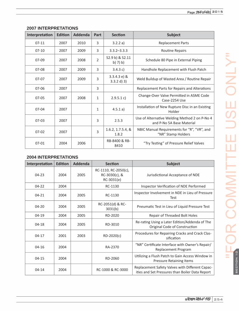
254
2015
SECTION 10
SEC
TIO
N 1
0
NB-23
2007 INTERPRETATIONSInterpretation Edition Addenda Part Section Subject
07-11 2007 2010 3 3.2.2 a) Replacement Parts
07-10 2007 2009 3 3.3.2–3.3.3 Routine Repairs
07-09 2007 2008 2 S2.9 b) & S2.11 b) 7) b) Schedule 80 Pipe in External Piping
07-08 2007 2009 3 3.4.3 c) Handhole Replacement with Flush Patch
07-07 2007 2009 3 3.3.4.3 e) & 3.3.2 d) 3) Weld Buildup of Wasted Area / Routine Repair
07-06 2007 3 Replacement Parts for Repairs and Alterations
07-05 2007 2008 1 2.9.5.1 c) Change-Over Valve Permitted in ASME Code Case-2254 Use
07-04 2007 1 4.5.1 a) Installation of New Rupture Disc in an Existing Holder
07-03 2007 3 2.5.3 Use of Alternative Welding Method 2 on P-No 4 and P-No 5A Base Material
07-02 2007 3 1.6.2, 1.7.5.4, & 1.8.2
NBIC Manual Requirements for “R”, “VR”, and “NR” Stamp Holders
07-01 2004 2006 RB-8400 & RB-8410 “Try Testing” of Pressure Relief Valves
2004 INTERPRETATIONSInterpretation Edition Addenda Section Subject
04-23 2004 2005RC-1110, RC-2050(c),
RC-3030(c), & RC-3031(e)
Jurisdictional Acceptance of NDE
04-22 2004 RC-1130 Inspector Verification of NDE Performed
04-21 2004 2005 RC-1130 Inspector Involvement in NDE in Lieu of Pressure Test
04-20 2004 2005 RC-2051(d) & RC-3031(b) Pneumatic Test in Lieu of Liquid Pressure Test
04-19 2004 2005 RD-2020 Repair of Threaded Bolt Holes
04-18 2004 2005 RD-3010 Re-rating Using a Later Edition/Addenda of The Original Code of Construction
04-17 2001 2003 RD-2020(c) Procedures for Repairing Cracks and Crack Clas-sification
04-16 2004 RA-2370 “NR” Certificate Interface with Owner’s Repair/Replacement Program
04-15 2004 RD-2060 Utilizing a Flush Patch to Gain Access Window in Pressure Retaining Items
04-14 2004 RC-1000 & RC-3000 Replacement Safety Valves with Different Capac-ities and Set Pressures than Boiler Data Report
"FO
R"F
OR
"FO
RS
EC
TIO
N 1
0"FO
RS
EC
TIO
N 1
0C
OM
MIT
TEE
US
EO
NLY
"
Page 284 of 400
Page 284 of 400
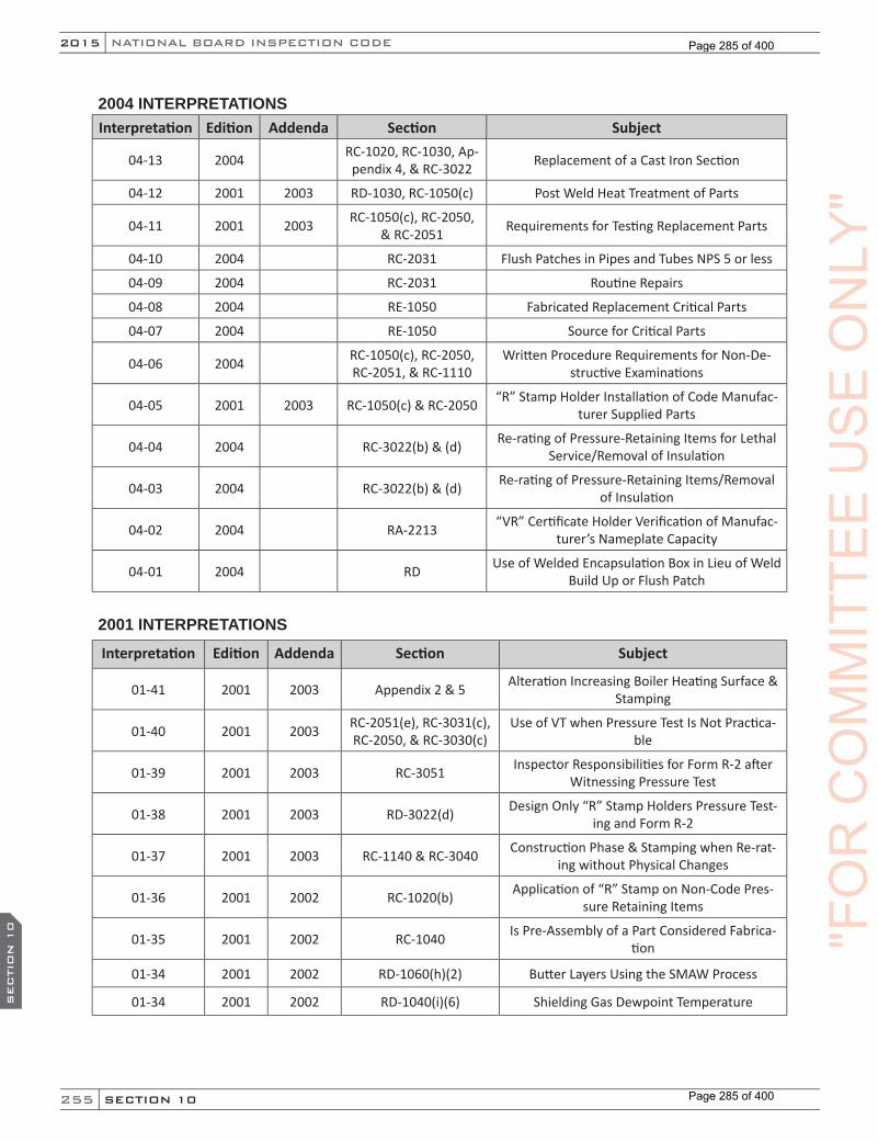
255
NATIONAL BOARD INSPECTION CODE2015
SECTION 10
SEC
TIO
N 1
0
2004 INTERPRETATIONSInterpretation Edition Addenda Section Subject
04-13 2004 RC-1020, RC-1030, Ap-pendix 4, & RC-3022 Replacement of a Cast Iron Section
04-12 2001 2003 RD-1030, RC-1050(c) Post Weld Heat Treatment of Parts
04-11 2001 2003 RC-1050(c), RC-2050, & RC-2051 Requirements for Testing Replacement Parts
04-10 2004 RC-2031 Flush Patches in Pipes and Tubes NPS 5 or less
04-09 2004 RC-2031 Routine Repairs
04-08 2004 RE-1050 Fabricated Replacement Critical Parts
04-07 2004 RE-1050 Source for Critical Parts
04-06 2004 RC-1050(c), RC-2050, RC-2051, & RC-1110
Written Procedure Requirements for Non-De-structive Examinations
04-05 2001 2003 RC-1050(c) & RC-2050 “R” Stamp Holder Installation of Code Manufac-turer Supplied Parts
04-04 2004 RC-3022(b) & (d) Re-rating of Pressure-Retaining Items for Lethal Service/Removal of Insulation
04-03 2004 RC-3022(b) & (d) Re-rating of Pressure-Retaining Items/Removal of Insulation
04-02 2004 RA-2213 “VR” Certificate Holder Verification of Manufac-turer’s Nameplate Capacity
04-01 2004 RD Use of Welded Encapsulation Box in Lieu of Weld Build Up or Flush Patch
2001 INTERPRETATIONS
Interpretation Edition Addenda Section Subject
01-41 2001 2003 Appendix 2 & 5 Alteration Increasing Boiler Heating Surface & Stamping
01-40 2001 2003 RC-2051(e), RC-3031(c), RC-2050, & RC-3030(c)
Use of VT when Pressure Test Is Not Practica-ble
01-39 2001 2003 RC-3051 Inspector Responsibilities for Form R-2 after Witnessing Pressure Test
01-38 2001 2003 RD-3022(d) Design Only “R” Stamp Holders Pressure Test-ing and Form R-2
01-37 2001 2003 RC-1140 & RC-3040 Construction Phase & Stamping when Re-rat-ing without Physical Changes
01-36 2001 2002 RC-1020(b) Application of “R” Stamp on Non-Code Pres-sure Retaining Items
01-35 2001 2002 RC-1040 Is Pre-Assembly of a Part Considered Fabrica-tion
01-34 2001 2002 RD-1060(h)(2) Butter Layers Using the SMAW Process
01-34 2001 2002 RD-1040(i)(6) Shielding Gas Dewpoint Temperature
"FO
RC
OM
MIT
TEE
US
EO
NLY
"
Page 285 of 400
Page 285 of 400
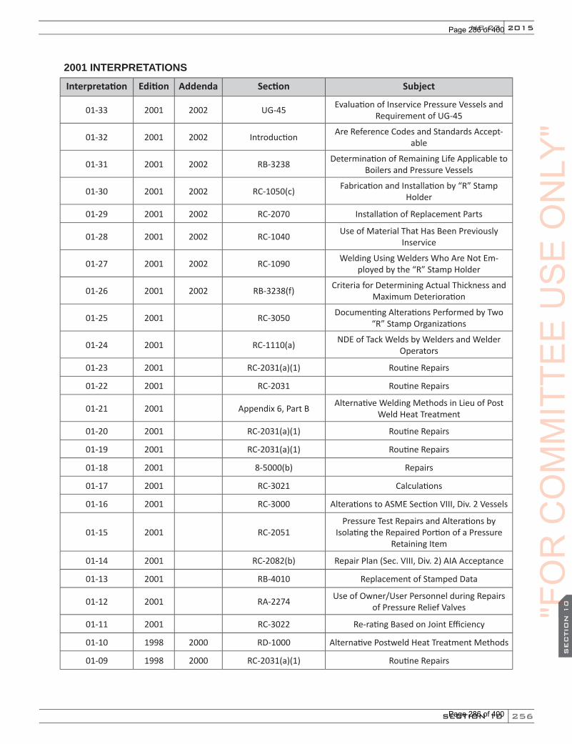
256
2015
SECTION 10
SEC
TIO
N 1
0
NB-23
2001 INTERPRETATIONS
Interpretation Edition Addenda Section Subject
01-33 2001 2002 UG-45 Evaluation of Inservice Pressure Vessels and Requirement of UG-45
01-32 2001 2002 Introduction Are Reference Codes and Standards Accept-able
01-31 2001 2002 RB-3238 Determination of Remaining Life Applicable to Boilers and Pressure Vessels
01-30 2001 2002 RC-1050(c) Fabrication and Installation by “R” Stamp Holder
01-29 2001 2002 RC-2070 Installation of Replacement Parts
01-28 2001 2002 RC-1040 Use of Material That Has Been Previously Inservice
01-27 2001 2002 RC-1090 Welding Using Welders Who Are Not Em-ployed by the “R” Stamp Holder
01-26 2001 2002 RB-3238(f) Criteria for Determining Actual Thickness and Maximum Deterioration
01-25 2001 RC-3050 Documenting Alterations Performed by Two “R” Stamp Organizations
01-24 2001 RC-1110(a) NDE of Tack Welds by Welders and Welder Operators
01-23 2001 RC-2031(a)(1) Routine Repairs
01-22 2001 RC-2031 Routine Repairs
01-21 2001 Appendix 6, Part B Alternative Welding Methods in Lieu of Post Weld Heat Treatment
01-20 2001 RC-2031(a)(1) Routine Repairs
01-19 2001 RC-2031(a)(1) Routine Repairs
01-18 2001 8-5000(b) Repairs
01-17 2001 RC-3021 Calculations
01-16 2001 RC-3000 Alterations to ASME Section VIII, Div. 2 Vessels
01-15 2001 RC-2051Pressure Test Repairs and Alterations by
Isolating the Repaired Portion of a Pressure Retaining Item
01-14 2001 RC-2082(b) Repair Plan (Sec. VIII, Div. 2) AIA Acceptance
01-13 2001 RB-4010 Replacement of Stamped Data
01-12 2001 RA-2274 Use of Owner/User Personnel during Repairs of Pressure Relief Valves
01-11 2001 RC-3022 Re-rating Based on Joint Efficiency
01-10 1998 2000 RD-1000 Alternative Postweld Heat Treatment Methods
01-09 1998 2000 RC-2031(a)(1) Routine Repairs
"FO
R"F
OR
"FO
RS
EC
TIO
N 1
0"FO
RS
EC
TIO
N 1
0C
OM
MIT
TEE
US
EO
NLY
"
Page 286 of 400
Page 286 of 400
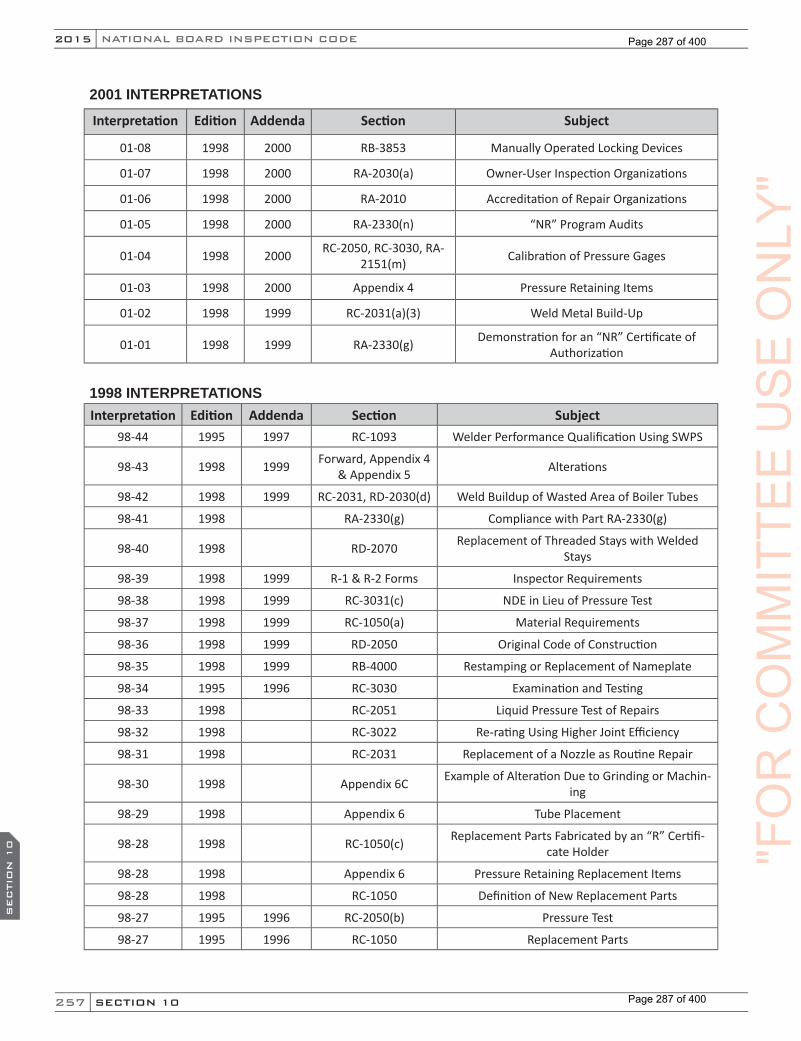
257
NATIONAL BOARD INSPECTION CODE2015
SECTION 10
SEC
TIO
N 1
0
2001 INTERPRETATIONS
Interpretation Edition Addenda Section Subject
01-08 1998 2000 RB-3853 Manually Operated Locking Devices
01-07 1998 2000 RA-2030(a) Owner-User Inspection Organizations
01-06 1998 2000 RA-2010 Accreditation of Repair Organizations
01-05 1998 2000 RA-2330(n) “NR” Program Audits
01-04 1998 2000 RC-2050, RC-3030, RA-2151(m) Calibration of Pressure Gages
01-03 1998 2000 Appendix 4 Pressure Retaining Items
01-02 1998 1999 RC-2031(a)(3) Weld Metal Build-Up
01-01 1998 1999 RA-2330(g) Demonstration for an “NR” Certificate of Authorization
1998 INTERPRETATIONSInterpretation Edition Addenda Section Subject
98-44 1995 1997 RC-1093 Welder Performance Qualification Using SWPS
98-43 1998 1999 Forward, Appendix 4 & Appendix 5 Alterations
98-42 1998 1999 RC-2031, RD-2030(d) Weld Buildup of Wasted Area of Boiler Tubes
98-41 1998 RA-2330(g) Compliance with Part RA-2330(g)
98-40 1998 RD-2070 Replacement of Threaded Stays with Welded Stays
98-39 1998 1999 R-1 & R-2 Forms Inspector Requirements
98-38 1998 1999 RC-3031(c) NDE in Lieu of Pressure Test
98-37 1998 1999 RC-1050(a) Material Requirements
98-36 1998 1999 RD-2050 Original Code of Construction
98-35 1998 1999 RB-4000 Restamping or Replacement of Nameplate
98-34 1995 1996 RC-3030 Examination and Testing
98-33 1998 RC-2051 Liquid Pressure Test of Repairs
98-32 1998 RC-3022 Re-rating Using Higher Joint Efficiency
98-31 1998 RC-2031 Replacement of a Nozzle as Routine Repair
98-30 1998 Appendix 6C Example of Alteration Due to Grinding or Machin-ing
98-29 1998 Appendix 6 Tube Placement
98-28 1998 RC-1050(c) Replacement Parts Fabricated by an “R” Certifi-cate Holder
98-28 1998 Appendix 6 Pressure Retaining Replacement Items
98-28 1998 RC-1050 Definition of New Replacement Parts
98-27 1995 1996 RC-2050(b) Pressure Test
98-27 1995 1996 RC-1050 Replacement Parts
"FO
RC
OM
MIT
TEE
US
EO
NLY
"
Page 287 of 400
Page 287 of 400

258
2015
SECTION 10
SEC
TIO
N 1
0
NB-23
1998 INTERPRETATIONSInterpretation Edition Addenda Section Subject
98-26 1998 RA-2262(b)(1) Resetting of PRV Springs per ASME Section 1, PG-72.3 or Section VIII, Div. 1, UG-126(c)
98-25 1998 RA-2262(b)(3) Stamping on Repair Nameplate
98-24 1998 RA-2242(c) “VR” Certificate Holders and Code Case 1923 & 1945
98-23 1995 Appendix 6, B-7 Head and Shell Thickness Limitations when In-stalling Nozzles
98-22 1998 RC-1010 Scope
98-21 1998 RA-2130(f) Requirements for Applicants for “R” Certificate of Authorization
98-20 1998 RC-3022 Re-rating
98-19 1998 RB-3237 Inspection Interval
98-18 1998 RC-2031(a)(1) Routine Repairs
98-17 1998 RA-2281 Testing Medium and Testing Equipment
98-16 1998 RA-3020 Prerequisites for Accreditation
98-15 1995 1996 RC-3022 & RC-3030(h)
Pressure Testing Requirements Related to Re-rat-ing Activities
98-14 1998 Appendix 6 Examples of Repairs and Alterations
98-14 1998 RC-1050 Replacement Parts
98-14 1998 RC-3022 Re-rating
98-14 RC-3020 Design
98-13 1995 1996 RA-2151(r) QC Manual Requirements
98-12 1995 1996 RA-2231(b)(1) Use of Code Case 2203 in Repairs
98-11 1995 1996 RA-3050 Owner-User Program Accreditation and Inspec-tions
98-10 1995 RC-1110 NDE Requirements for ASME Section I Tube Sheet Repairs
98-09 1995 RB-3640 Inspection Requirements
98-08 1995 1996 RD-2010 Repair Methods
98-07 1995 1996 RA-2330(d) ASME Section XI Program Boundary Components
98-06 1995 1996 RC-1090 Welding Non-Pressure Parts in a Pressure Retain-ing Item
98-06 1995 1996 RD-1010 Alternative Methods of NDE
98-05 1995 1996 Forward Determination of Repairs Must be Made
98-04 1995 1996 RC-2031 Routine Repairs
98-03 1995 RB-3238(f) Interrupted Service
98-02 1995 1996 RA-2231 Conditions of Use
98-01 1995 1997 RC-2031(a)(1) Attachments
"FO
R"F
OR
"FO
RS
EC
TIO
N 1
0"FO
RS
EC
TIO
N 1
0C
OM
MIT
TEE
US
EO
NLY
"
Page 288 of 400
Page 288 of 400
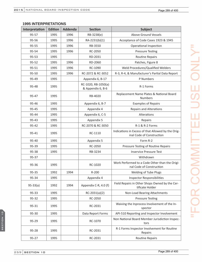
259
NATIONAL BOARD INSPECTION CODE2015
SECTION 10
SEC
TIO
N 1
0
1995 INTERPRETATIONSInterpretation Edition Addenda Section Subject
95-57 1995 1996 RB-3238(e) Above Ground Vessels
95-56 1995 1996 RA-2231(b)(1) Acceptance of Code Cases 1923 & 1945
95-55 1995 1996 RB-3550 Operational Inspection
95-54 1995 1996 RC-2050 Pressure Testing
95-53 1995 RD-2031 Routine Repairs
95-52 1995 1996 RD-2060 Patches, Figure 8
95-51 1995 1996 RC-1090 Weld Procedures/Qualified Welders
95-50 1995 1996 RC-2072 & RC-3052 R-3, R-4, & Manufacturer’s Partial Data Report
95-49 1995 Appendix 6, B-17 P Numbers
95-48 1995 RC-1020, RB-1050(a) & Appendix 6, B-6 R-1 Forms
95-47 1995 RB-4020 Replacement Name Plates & National Board Numbers
95-46 1995 Appendix 6, B-7 Examples of Repairs
95-45 1995 Appendix 4 Repairs and Alterations
95-44 1995 Appendix 6, C-5 Alterations
95-43 1995 Appendix 5 Repairs
95-42 1995 RC-2070 & RC-3050 R-1 & R-2 Forms
95-41 1995 RC-1110 Indications in Excess of that Allowed by the Orig-inal Code of Construction
95-40 1995 Appendix 5 Form R-2
95-39 1995 RC-2050 Pressure Testing of Routine Repairs
95-38 1995 RB-3234 Inservice Pressure Test
95-37 Withdrawn
95-36 1995 RC-1020 Work Performed to a Code Other than the Origi-nal Code of Construction
95-35 1992 1994 R-200 Welding of Tube Plugs
95-34 1995 Appendix 4 Inspector Responsibilities
95-33(a) 1992 1994 Appendix C-R, 4.0 (f) Field Repairs in Other Shops Owned by the Cer-tificate Holder
95-33 1995 RC-2031(a)(2) Non-Load Bearing Attachments
95-32 1995 RC-2050 Pressure Testing
95-31 1995 RC-2031 Waiving the Inprocess Involvement of the In-spector
95-30 1995 Data Report Forms API-510 Reporting and Inspector Involvement
95-29 1995 RC-1070 Non National Board Member Jurisdiction Inspec-tors
95-28 1995 RC-2031 R-1 Forms Inspector Involvement for Routine Repairs
95-27 1995 RC-2031 Routine Repairs
"FO
RC
OM
MIT
TEE
US
EO
NLY
"
Page 289 of 400
Page 289 of 400

260
2015
SECTION 10
SEC
TIO
N 1
0
NB-23
1995 INTERPRETATIONSInterpretation Edition Addenda Section Subject
95-27 1995 RC-2050 Registration of R-1 Forms
95-27 1995 RC-2060 Application of the “R” Symbol Stamp
95-27 1995 RC-2072 Responsibility for Performing Pressure Test
95-26 1995 RA-2262 Valve Nameplate Contents
95-25 1995 Appendix 5 Inspectors Requirements for Form R-1 on Rou-tine Repairs
95-24 1995 Appendix 2 Nameplate Stamping and Layout
95-23 1995 RC-1010 Documentation of Repairs to Non-Symbol Stamped Cargo Vessels
95-22 1995 RC-3020 & RC-3021 Reclassification of Pressure Retaining Items
95-21 1995 Appendix 4 Repairs to PWHT Vessels Without Subsequent PWHT
95-20 1995 Foreword Use of Earlier Edition and Addenda
95-19 1995 RC-1000 Original Code of Construction/Edition/Addenda
95-18 1992 1994 Appendix C-NR & NR-1000 Scope and Applicability
95-17 1992 1994 R-404 Documenting Repairs/Responsibility for Work Performed by Others
95-16 1992 1994 R-302.1 Owner/User Supplied Weld Procedures
95-15 1992 1994 R-307 Use of Replacement Parts/Assemblies from Oth-er Inservice Vessels
95-14 1992 1994 R-202 Repairs to PWHT Vessels without Subsequent PWHT
95-13 1992 1994 U-106 Maximum Period between Inspection Intervals
95-12 1992 1994 U-107 Inspection of Corrosion and Other Deterioration
95-11 1992 1994 R-503 Re-rating of Complete Boilers or Pressure Vessels
95-10 1992 1994 R-301.2.2 Owner User Acceptance Inspection of Repairs and Alterations
95-09 1992 1994 Chapter III, Supple-ment 3
Welding Methods as an Alternative to Postweld Heat Treatment
95-08 1992 1994 Appendix C-R Guide for Completing Form R-1
95-07 1992 1994 Appendix C-R, 3.0 Renewal of “R” Certificate of Authorization
95-06 1992 1993 R-401.2.2 Access Openings
95-05 1992 1993 Purpose and Scope When Does the NBIC Take Effect on New Boilers or Pressure Vessels
95-04 1992 1993 U-107 Inspection for Corrosion and Other Deterioration
95-03 1992 1993 R-200, R-404, R-505 Use of Similar & Non-Similar Base Metals/Re-pair-Alteration
95-02 1992 1993 R-307 Use of R-Form When Replacing Parts with Differ-ent Materials without Welding
95-01 All What Editions of the NBIC Governs
"FO
R"F
OR
"FO
RS
EC
TIO
N 1
0"FO
RS
EC
TIO
N 1
0C
OM
MIT
TEE
US
EO
NLY
"
Page 290 of 400
Page 290 of 400

261
NATIONAL BOARD INSPECTION CODE2015
SECTION 10
SEC
TIO
N 1
0
1992 INTERPRETATIONSInterpretation Edition Addenda Section Subject
94-2 1992 Chapter III, R-301.1 Inspector Approval for Routine Repairs
94-1 1989 Chapter III Repair of Valves Covered by B31.1
93-6 1992 Chapter III Re-rating by Performing Radiography & Recalculating Joint Efficiency
93-5 1992 Chapter III, R-503(d)
Requirement for Pressure Test when Re-rating a Vessel
93-4 1992 Chapter III, R-301.2 Owner User Acceptance Inspection of Alterations
93-2 1992 Alterations
93-1 1992 Requirements when More than One Inspector is Involved in a Repair
92-7 1992 Alterations with Different Certificate Holders Perform-ing Design Calculations and Physical Work
92-6 1992 Out of State Organizations Performing Repairs
92-5 1992 Alternative Requirements of NBIC when There is No Jurisdiction
92-4 1992 Chapter III, Sup-plement 1
Replacement of Tubes with Equal or Greater Allow-able Stress
"FO
RC
OM
MIT
TEE
US
EO
NLY
"
Page 291 of 400
Page 291 of 400
262
2015
SECTION 11 SEC
TIO
N 1
1
NB-23
PART 3, SECTION 11 REPAIRS AND ALTERATIONS — INDEX
A
Acceptance(Foreword), (1.4.5), (1.5), (2.3.3), (2.10), (2.10.4), (2.10.5), (2.10.6), (3.3.4), (3.7.9.1), (3.7.9.2), (3.10), (3.10.2), (3.10.3), (4.5.6), (4.6), (4.7.6), (5.3.6), (S5.3.4), (S5.8), (S5.8.4), (S5.8.5), (S5.8.6) (8.2), (9.1)
Accreditation(Introduction), (9.1)
Programs(Introduction)
Acoustic Emission(S1.5)
Addenda(Introduction), (1.4.2), (8.2), (9.1), (10.1)
Administrative Requirements(Introduction), (8.1)
Alteration(Foreword), (Introduction), (1.4.1), (S1.2), (7.1), (7.2), (9.1)
American National Standards Institute (ANSI)(Foreword), (S3.5), (9.1)
Appurtenances(2.4.4), (2.5.3.1), (2.10.1), (3.3.4), (3.5.3), (3.5.3.2), (4.6), (5.2.2), (5.2.5), (5.2.7), (S5.5.7), (S5.8.1), (S6.13.4), (S6.13.6), (S6.14.3), (S6.17)
Ash Removal(2.6.2), (3.6.2), (S4.2), (S4.5), (S4.6)
ASME Code(1.4.5.1), (S1.2), (S1.3), (S1.4), (S2.5), (S3.5), (S3.6.2), (9.1)
Authority(1.4.1), (4.3.4), (5.2.9), (9.1)
Authorization(Foreword), (9.1)
B
Biomass(S4.1), (S4.2), (S4.4)
Blowdown(1.4.5.1.1), (2.7.5), (3.6.3), (3.8.1.3)
Blowoff(2.5.1.2), (2.6.3.1), (2.7.5), (2.10.2), (3.7.5), (3.7.7), (3.7.7.1), (3.7.8.1), (3.8.1.5), (3.11)
Boiler InstallationHeating Boilers(3.1)Hot Water Supply Boilers(3.1)Power Boilers(2.1)Report(1.4.5)Steam Heating(3.1)
BoilersCast Iron(1.4.5.1.1), (3.8.1.3), (3.9.2), (3.9.3)Electric(1.4.5.1.1), (2.5.1.2), (2.7.5), (2.8.1), (2.9.1.1), (2.9.1.3), (3.8.1.2)Firetube(2.8.1), (2.9.1.3), (3.3.1.1), (3.9.2)Historical/Hobby(Introduction)Locomotive(Introduction)Modular(3.7.8.2)Organic and Inorganic Fluid(2.9.1.3), (3.9.2)
Burners(2.7.2), (3.7.3), (S4.2), (S4.6), (S5.5.7) "F
OR
CO
MM
ITTE
EU
SE
ON
LY"
Page 292 of 400
Page 292 of 400
263
NATIONAL BOARD INSPECTION CODE2015
SECTION 11SEC
TIO
N 1
1
C
Calculations(3.7.9.1), (3.7.9.2), (4.5.4), (5.3.4), (S1.3), (7.3), (7.4), (8.4)
Capacity(1.4.5.1), (1.4.5.1.1), (2.4.1), (2.5.1.1), (2.5.1.3), (2.5.3.2), (2.5.4), (2.9.1.1), (2.9.1.3), (2.9.2), (2.9.3), (2.9.4), (2.9.5), (2.9.6), (3.4.1), (3.4.5), (3.5.4), (3.7.6), (3.7.7.1), (3.7.9.1), (3.7.9.2), (3.9.1.1.2), (3.9.1.5), (3.9.1.6), (3.9.2), (3.9.3), (3.9.4), (3.9.4.3), (3.9.4.7), (3.9.5.2), (3.9.5.3), (4.5.1), (4.5.4), (4.5.5), (4.5.6), (5.3.1), (5.3.4), (5.3.5), (5.3.6), (S2.1), (S2.2), (S2.3), (S2.4), (S3.6) (S2.8.1), (S2.11), (S2.15), (S5.3.1), (S5.3.3), (S5.4.1), (S5.5.8), (S5.7.4), (S5.7.5), (S5.7.6), (S6.8), (S6.13.9), (S6.13.11.2), (9.1)
Capacity Certification(5.3.1), (9.1)
Carbon Recycle(S4.2)
Certificate of Authorization(Introduction), (9.1)
Certification(1.1), (1.4), (1.4.1), (1.4.2), (1.4.5.1.1), (5.3.1), (9.1)
Chimney or Stack(2.6.1), (3.6.1), (S5.6.1), (9.1)
Cleaning(2.4.4), (2.6.3), (3.6.3), (3.7.4), (3.7.6), (3.8.1.2), (3.8.1.3), (5.2.7)
Clearances(1.4.5.1.1), (2.3.3), (3.3.4), (4.3.2), (S5.3.4), (S5.4.2)
Code Interpretation(Introduction), (8.1), (8.2), (8.4)
Code of Construction(Foreword), (1.4.2), (1.4.5.1.1), (2.10.1), (2.10.2), (2.10.3), (3.3.1.1), (3.7.5.1), (3.7.8.1), (3.7.9.1), (3.7.9.2), (3.8.1.4), (3.10.1), (4.5.3), (4.5.4), (4.5.5), (4.6), (5.2.5), (5.3), (5.3.3), (5.3.4), (5.3.5), (5.4), (5.2.2), (5.3.7), (5.3.7.1), (S5.5.2), (S5.7.1), (S5.7.2), (S5.7.3), (S5.7.4), (S5.7.5), (S5.7.6), (S5.8.1), (S5.8.3), (S6.4.5), (S6.5.2), (S6.7), (S7.2), (S7.7), (7.1), (9.1)
Codes and Standards(Foreword), (3.5.3.2), (S4.6), (S5.5.7)
Combustion Air(1.4.5.1), (1.4.5.1.1), (2.5.4), (3.5.4), (S4.2), (S4.6), (S5.5.8)
Commissioned Inspector(1.4.1), (9.1)
Compressible Fluid Service(4.5.3)
Condensate(2.5.1.2), (2.7.4), (S1.1)
Connections(1.4.5.1), (1.4.5.1.1), (2.5.1.2), (2.5.1.4), (2.6.3.2), (2.7.5), (2.8.1), (2.8.2.1), (2.9.6), (2.10.1), (3.5.1), (3.7.4), (3.7.5.1), (3.7.5.2), (3.7.6), (3.7.7.1), (3.8.1.1), (3.8.1.3), (3.8.1.4), (3.8.1.5), (3.8.1.2), (3.9.1.1.2), (3.9.1.2), (3.9.4.3), (3.9.4.4), (4.3.4), (4.4.1), (5.2.9), (S3.2.3), (S3.6), (S5.5.3), (S5.5.4), (S5.5.5), (S5.7.2), (S5.7.6), (S5.8.1)
Continued Service (DOT)(Introduction), (7.1)
Controls(2.5.3.1), (2.5.3.2), (2.5.3.3), (2.5.6), (2.8), (2.9.2), (3.5.3), (3.5.3.2), (3.5.3.3), (3.5.6), (3.7.5), (3.8), (3.8.1.4), (3.8.1.7), (3.8.2.3), (3.8.2.4), (3.8.2.6), (3.8.3.1), (3.10.2), (4.4), (S1.2), (S2.1), (S4.2), (S4.6), (S5.1), (S5.5.7), (S5.5.10), (9.1)
Conversion(7.2), (7.3), (7.4.1), (9.1)
Cracks(S1.6), (S3.6), (S5.5.7)
D
Defect(S3.6)
Dents(S1.1)
"FO
RC
OM
MIT
TEE
US
EO
NLY
"
Page 293 of 400
Page 293 of 400

264
2015
SECTION 11 SEC
TIO
N 1
1
NB-23
Design(Foreword), (Introduction), (1.2), (1.3), (2.3.1), (2.5.1.3), (2.6.3.2), (2.7.3), (2.8.1), (2.9.1), (2.9.1.3), (2.9.2), (2.9.6), (3.3.1.1), (3.5.1), (3.7.7.1), (3.7.9.1) (3.8.2.4), (4.3.1), (4.4.2), (4.5.6), (5.2), (5.2.1), (5.2.4), (5.2.6), (5.3.6), (S1.2), (S1.3), (S1.4), (S2.1), (S3.2.1), (S3.4), (S3.6), (S4.2), (S5.2), (S5.3.1), (S5.5.3), (S5.5.4), (S5.5.5), (S5.5.7), (S5.7.2), (S5.7.6), (7.1), (8.4), (9.1)
Documentation(Foreword), (Introduction) (1.3), (1.4.1), (S1.3), (7.1), (9.1)
DOT (Transport Tanks)(Introduction), (7.1), (9.1)
Drains(2.4.3), (2.6.3.2), (2.6.3.3), (2.7.3), (2.8.1), (2.9.6), (3.6.3), (3.7.7.1), (4.5.6), (5.3.6), (S5.5.2), (S5.6.2), (S5.6.3), (S5.7.6)
Drawings(8.4)
E
Economizers(2.5.1.4), (2.6.3.3), (2.7.5), (2.9.4), (2.10.2)
Effective Edition(Foreword)
Electrical(1.4.1), (2.5.3), (2.5.3.1), (2.5.3.3), (3.4.1), (3.5.3), (3.8.3.1), (S3.2.1), (S5.5.7)
Emissions(S4.2), (S4.6)
Engineering Judgment (Foreword), (7.2)
Equipment Certification(1.4.2)
Equipment Room Requirements(2.3.3), (2.4), (2.5.3.2), (2.5.4), (2.5.5), (3.4), (3.5.3.1), (3.5.3.2), (3.5.4), (3.6.3), (S5.5.7), (S5.5.8), (S5.5.9)
Examination(Introduction), (2.10.3), (5.4), (S1.6), (S5.8.3), (9.1)
Exit(2.4.1), (2.4.2), (3.4.1), (3.4.2), (S5.4.1), (S5.4.2), (9.1)
Expansion Tanks(3.7.9.1), (3.9.2), (S5.1), (S5.5.2), (S5.5.3), (S5.5.7)
F
Facility(1.4.1), (2.5.3.2), (S3.5), (S4.2)
Failure Mechanisms(Introduction)
Fatigue(S1.3), (S1.4)
Feedwater(2.5.1.1), (2.5.1.2), (2.5.1.3), (2.5.1.3), (2.5.1.4), (2.8.1), (2.9.1.3), (2.10.2), (3.7.4), (3.7.8.2), (3.8.1.3), (3.8.1.5)
Field(4.6), (S1.5), (7.4.1), (9.1)
Fillet Weld(3.3.1.1)
Firebox(2.9.1.3), (3.5.3), (3.7.6), (3.9.2), (S5.5.7)
Fittings(2.6.3.1), (2.7.3), (2.7.5), (2.9.1.2), (2.10.2), (3.8), (3.8.1.2), (3.8.1.3), (3.8.1.5), (3.8.1.7), (3.8.2.6), (4.5.6), (5.3.6), (S3.2.3), (S3.6), (9.1)
Flanges(2.6.3.2), (2.9.1), (5.2.4), (S5.5.5), (S5.6.2)
Fluidized Bed(S4.2), (S4.6)
Flyash(S4.6)
Forced-Flow Steam Generators(2.5.1.3), (2.7.5), (2.9.1.3)
Foundations(2.3.1), (4.3.1), (S3.2.1), (S5.3.1) "F
OR
CO
MM
ITTE
EU
SE
ON
LY"
Page 294 of 400
Page 294 of 400
265
NATIONAL BOARD INSPECTION CODE2015
SECTION 11SEC
TIO
N 1
1
Fuel(1.4.5.1), (1.5.1.1), (2.4.1), (2.5.1.2), (2.5.2), (2.5.3.2), (2.5.4), (2.8.1), (2.9.1.3), (2.9.1.3), (3.4.1), (3.5.2), (3.5.3), (3.5.4), (3.7.5), (3.8.1.3), (3.8.1.4), (3.8.1.5), (3.8.2.3), (3.8.2.4), (3.8.2.5), (3.8.3.1), (3.9.2), (3.9.3), (3.9.4), (S1.1), (S4.1), (S4.2), (S4.4), (S4.5), (S4.6), (S5.4.1), (S5.5.6), (S5.5.7), (S5.5.8), (9.1)
Full Penetration Weld(S5.5.5)
G
Gage Glass(1.4.5.1), (1.4.5.1.1), (2.8.1), (3.7.4), (3.7.5), (3.8.1.2), (3.8.1.3), (3.8.1.5), (3.8.1.6)
Gages(2.8), (2.8.1), (3.8.1.1), (3.8.1.3), (3.8.2.1)
Grooving(1.1)
H
Hangers(3.3.1.1), (5.2.6)
Heat Treatment(Introduction), (5.2.8)
High Temperature Water(2.5.1.2), (2.5.1.4), (2.6.3.1), (2.8.3), (2.9.1), (2.9.1.3), (2.9.1.4), (2.9.6), (3.9.5.2), (3.9.5.3), (S5.5.4), (S5.5.5), (S5.5.7), (9.1)
Hold Time(S3.2.2)
Hydrostatic Test(2.3.1), (2.7.3), (3.7.5.1), (3.7.9.1), (4.3.1), (S5.8.2), (9.1)
I
Induced Draft Fan(S4.2), (S4.6)
Inservice Inspection(Introduction), (1.4.1), (8.1), (9.1)
Inspection(Foreword), (Introduction), (1.4), (1.4.1), (1.4.2), (1.4.4), (1.4.5), (2.3.3), (2.4.2), (2.7.5), (2.10.1), (2.10.6), (3.3.2), (3.3.4), (3.4.2), (3.7.4), (3.10.2), (3.10.3), (4.3.2), (4.5.6), (4.7.2), (5.3.6), (5.4), (S1.2), (S3.2.1), (S5.3.4), (S5.4.2), (S5.8.1), (S5.8.6), (7.1), (8.4), (9.1)
Inquiries(Foreword), (8.1), (8.2), (8.5)
Instruments and Controls(4.4)
Insulation(3.3.2), (S3.6.1), (S5.3.2), (S5.5.5)
Interpretations(Foreword), (8.1), (8.4), (10.1), (10.2)
Intervening(2.9.1.2), (2.9.3), (3.7.8.2), (3.9.2), (3.9.3), (3.9.4), (4.5.6), (5.3.6), (S5.7.6), (9.1)
J
Jurisdiction(Foreword), (Introduction), (1.1), (1.3), (1.4), (1.4.1), (1.4.3), (1.4.5), (1.4.5.1), (1.4.5.1.1), (1.5), (2.3.1), (2.3.2), (2.3.3), (2.5.2), (2.5.3.2), (2.5.3.3), (2.5.4), (2.6.1), (2.6.2), (2.7.1), (2.7.2), (2.7.5), (2.9.6), (2.10.4), (2.10.5), (2.10.6), (3.3.3), (3.3.4), (3.5.2), (3.5.3), (3.5.4), (3.6.1), (3.6.2), (3.7.2), (3.7.3), (3.10.3), (4.3.1), (4.3.4), (4.4.1), (4.5.4), (4.5.6), (4.6), (5.2.9), (5.3.4), (5.3.6), (S3.2.1), (S3.5), (S4.3), (S5.3.1), (S5.3.2), (S5.3.4), (S5.5.5), (S5.6), (S5.5.7), (S5.5.8), (S5.6.1), (S5.8.4), (S5.8.5), (S5.8.6), (9.1)
K
L
Ladders and Runways(2.4.2), (3.4.2), (S5.4.2)
Level Indicating Device(4.4.1)
Lighting(2.5.5), (3.5.5), (S5.5.9)
Liquid Carbon Dioxide Storage Vessels(S3.1)
"FO
RC
OM
MIT
TEE
US
EO
NLY
"
Page 295 of 400
Page 295 of 400
266
2015
SECTION 11 SEC
TIO
N 1
1
NB-23
Loading(2.3.1), (3.3.1.1), (4.3.1), (S1.2), (S1.3), (S1.4), (S1.5), (S3.2.1), (S5.3.1)
Locations(2.5.3), (2.5.3.2), (3.5.3.1), (3.5.3.2), (S3.4), (S5.5.7), (S5.7.3), (S5.7.6), (9.1)
Low-Water Fuel Cutoff(1.4.5.1), (1.4.5.1.1), (2.8.1), (3.7.5), (3.8.1.3), (3.8.1.5), (3.8.2.4), (3.8.2.5)
M
Maximum Allowable Working Pressure (MAWP) (1.4.5.1.1), (2.7.3), (2.7.5), (2.8.2.1), (2.9.1.3), (2.9.1.4), (2.9.2), (3.8.1.4), (3.9.2), (3.9.3), (3.9.4), (3.9.5.1), (3.9.5.2), (3.9.5.3), (4.5.2), (4.5.5), (4.7.3), (5.3.2), (5.3.5), (S1.5), (S2.13.9.5), (S3.6), (S3.6.1), (S5.7.5), (9.1)
Metering Device(S4.2), (S4.5)
Metrication Policy(Introduction), (7.1), (7.2), (7.3), (7.4)
Minimum Thickness(3.3.1.1)
N
National Board(Foreword), (Introduction), (1.4.1), (1.4.5.1), (1.4.5.1.1), (2.9.1.1), (3.9.1.6), (3.9.2), (3.9.3), (3.9.4), (3.9.5.2), (3.9.5.3), (4.5.1), (4.5.4), (5.3.1), (5.3.4), (8.1), (8.5), (9.1), (10.1)
NBIC Committee(Foreword), (Introduction), (8.1), (8.5)
Nondestructive Examination(2.10.3), (S1.6), (S5.8.3)
Nuclear Items(Introduction), (9.1)
O
Oil Heaters(3.7.1)
Operating Parameters (Yankee Dryers)(S1.2), (S1.3), (S1.4), (S1.6)
Operating Systems(2.7), (3.7), (S4.6), (S5.2), (S5.5.7)
Organization(Foreword), (Introduction), (1.4.3), (2.5.3.3), (3.5.3), (S5.5.7), (9.1)
Overfire Air(S4.2), (S4.6)
Overheating(3.8.1.2), (3.8.2.4), (S5.5.7)
Owner(Introduction), (1.1), (1.3), (1.4.1), (1.4.3), (1.4.5), (2.10.6), (3.10.3), (4.5.4), (4.6), (5.3.4), (5.4), (S1.2), (S5.8.6), (9.1)
Owner-User(Introduction), (1.1), (1.2), (1.3), (1.4.5.1), (1.4.5.1.1), (S4.2), (9.1)
Owner-User Inspection Organization(Introduction), (9.1)
P
Parts(Foreword), (Introduction), (2.6.3.3), (2.9.2), (3.7.4), (3.7.7.1), (S1.3), (7.4), (8.4), (9.1)
Permissible Mountings (PRD)(3.9.4.2)
Personnel Safety(Introduction), (S1.5), (S3.5), (S5.7.6)
Piping(Foreword), (1.1), (1.3), (1.4.1), (1.4.2), (1.4.4), (1.4.5.1), (1.4.5.1.1.1), (2.1), (2.3.1), (2.5.1.2), (2.5.1.3), (2.5.1.4), (2.7.3), (2.7.5), (2.8.1), (2.8.2), (2.9.2), (2.9.5), (2.9.6), (2.10.1), (2.10.2), (3.3.1), (3.3.4), (3.7.4), (3.7.5), (3.7.6), (3.7.7.1), (3.7.7.2), (3.7.9.1), (3.7.9.2), (3.8.1.2), (3.8.1.3), (3.8.2.1), (3.9.1.5), (3.9.1.6), (3.9.2), (3.9.3), (3.9.4), (3.9.4.2), (3.9.4.7), (3.11), (4.3.2), (4.3.3), (4.5.3), (4.5.4), (4.5.6), (4.6), (4.7.5), (5.1), (5.2), (5.2.1), (5.2.2), (5.2.3), (5.2.4), (5.2.5), (5.2.6), (5.2.7), (5.3), (5.3.1), (5.3.2), (5.3.3), (5.3.4), (5.3.6), (S3.2.1), (S3.6), (S4.5), (S4.6), (S5.1), (S5.3.1), (S5.5.1), (S5.5.2), (S5.5.3), (S5.5.4), (S5.5.5), (S5.6.2), (S5.7.6), (S5.8.1), (S5.8.2), (9.1)
Pneumatic(S4.5)
"FO
RC
OM
MIT
TEE
US
EO
NLY
"
Page 296 of 400
Page 296 of 400
267
NATIONAL BOARD INSPECTION CODE2015
SECTION 11SEC
TIO
N 1
1
Postweld Heat Treatment(5.2.8), (9.1)
Potable Water Heater(1.1), (1.4.5), (1.4.5.1), (1.4.5.1.1), (2.1), (3.1), (3.5.3.2), (3.7.4), (3.7.5), (3.7.5.2), (3.7.7.2), (3.7.9.2), (3.8.3), (3.9.4), (3.9.4.3), (3.11), (9.1)
Preheating(5.2.8)
Pressure Control(3.7.5), (3.8.1.4), (3.8.1.6)
Pressure Reducing Valve(2.7.3), (2.9.5), (S2.1), (S2.5)
Pressure Relief Device(1.4.5.1.1), (2.9), (2.9.6), (4.4.2), (4.5), (4.5.1), (4.5.2), (4.5.3), (4.5.4), (4.5.5), (4.5.6), (5.3), (5.3.1), (5.3.2), (5.3.3), (5.3.4), (5.3.5), (5.3.6), (S5.5.2), (S5.7.2), (S5.7.3), (S5.7.4), (S5.7.5), (S5.7.6)
Mounting(3.9.1), (3.9.1.1.1), (3.9.1.3), (3.9.4.2), (3.9.4.5)
Pressure-Retaining Item (PRI)(Foreword), (Introduction), (1.1), (1.2), (1.3), (1.4.1), (1.4.2), (1.4.4), (1.5), (S1.3), (9.1)
Pressure Testing(2.10.2), (3.10.1), (4.3.1), (4.6), (5.2.6), (S5.8.2)
Yankee Dryers(S1.5)
Pressure Vessels(Foreword), (Introduction), (1.1), (1.3), (1.4.1), (1.4.2), (1.4.4), (2.7.5), (2.9.3), (2.9.4), (3.8.1.2), (4.1), (4.3.1), (4.3.2), (4.4.2), (4.5), (4.5.2), (4.5.3), (4.5.4), (4.5.6), (4.6), (5.3.2), (S3.6.1), (S4.5), (S5.2), (S5.6.2), (S5.7.4), (S5.7.6)
Pumps(2.5.1.3), (3.9.4), (S5.1), (S5.5.1), (S5.5.2), (S5.5.3), (S5.5.4), (S5.5.7), (S5.8.2)
Q
R
Repair(1.4.1), (2.9.2), (4.5.6), (5.3.6), (S1.2), (S1.6), (S3.5), (7.1), (7.2), (9.1)
Repair Organization(Introduction)
Request(Foreword), (Introduction), (1.4.1), (8.1), (8.3), (8.4)
Responsibility(Foreword), (Introduction), (1.3), (1.4.1)
Return Pipe Connections(3.7.5.1), (3.7.6)
Review(Foreword), (Introduction), (1.4.3), (4.5.4), (5.2.8), (5.3.4), (S1.2), (S1.5), (7.3), (8.4), (9.1)
Revisions(Foreword), (Introduction), (8.1), (8.3)
Rupture Disk(4.5.1), (4.5.4), (5.3.1), (5.3.4), (S5.7.2)
S
Safe Point of Discharge(2.9.6), (3.9.1.5), (9.1)
Safety(Foreword), (Introduction), (1.1), (1.4.5.1.1), (2.4.2), (2.5.3.3), (2.7.3), (3.4.2), (3.5.3), (3.8.1.4), (3.8.2.3), (3.8.2.4), (S1.5), (S3.5), (S4.6), (S5.4.2), (S5.5.1), (S5.5.7), (7.2), (9.1)
Safety Device(Introduction), (9.1)
Safety Valve/Safety Relief Valve(1.4.5.1.1), (2.5.1.1), (2.9.1), (2.9.1.1), (2.9.1.2), (2.9.1.3), (2.9.1.4), (2.9.3), (2.9.4), (2.9.5), (2.9.6), (3.7.4), (3.7.5), (3.7.7.1), (3.7.8.1), (3.7.9.1), (3.7.9.2), (3.8.2.1), (3.9.1.1), (3.9.1.1.1), (3.9.1.1.2), (3.9.1.3), (3.9.1.4), (3.9.1.4), (3.9.1.6), (3.9.3), (3.9.4), (3.9.4.1), (3.9.4.2), (3.9.4.3), (3.9.4.5), (3.9.4.6), (3.9.4.7), (3.9.5), (3.9.5.1), (3.9.5.2), (S1.2), (S2.5), (S3.6), (S5.5.2), (S5.5.7), (9.1)
Safety Valve Capacity(3.7.7.1), (3.9.2), (S2.2)
Scope of Activities (Accreditation)(Introduction)
Service Fluid(S5.7.2)
"FO
RC
OM
MIT
TEE
US
EO
NLY
"
Page 297 of 400
Page 297 of 400
268
2015
SECTION 11 SEC
TIO
N 1
1
NB-23
Set Pressure(1.4.5.1), (1.4.5.1.1), (2.7.3), (2.7.5), (2.8.1), (2.9.1.4), (2.9.2), (2.9.3), (3.7.4), (3.9.3), (3.9.4), (4.4.2), (4.4.5), (4.5.5), (5.3.5), (S5.7.5), (9.1)
Settings(2.3.1), (2.9.1.4), (4.3.1), (S3.2.1), (S5.3.1), (S5.3.3), (S5.5.7), (9.1)
Shop(4.6), (9.1)
Sleeve(2.5.1.2)
Specifications(3.10.2), (S4.2), (S5.5.1)
Stamping(Introduction), (1.4.5.1.1), (4.7.2), (7.1)
Steam Heating Boilers(1.1), (1.4.5), (3.1), (3.5.3.1), (3.7.5), (3.8.1.6), (S4.4)
Steam Supply(2.7.3), (2.8.2), (2.9.5)
Stop Valves(1.4.5.1), (1.4.5.1.1), (2.5.1.4), (2.7.3), (2.9.2), (2.10.2), (3.7.5), (3.7.5.1), (3.7.5.2), (3.7.8.2), (4.5.6), (4.7.5), (5.3.6), (S5.6.2), (S5.7.6), (S5.8.2)
Structural Steel(2.3.2), (3.3.1.1), (3.3.3), (S5.3.2)
Superheaters(2.10.2)
Supports(Introduction), (2.3.1), (3.3.1), (3.3.1.1), (3.3.2), (4.3.1), (5.2.6), (S3.2), (S3.2.1), (S5.3.1), (S5.3.2), (S5.5.5), (S11.10.4)
Suspension Burner(S4.2)
System Testing(2.10.4), (S5.8.4)
T
Technical Inquiries(8.1)
Temperature Controls(3.8.3.1)
Testing(Foreword), (Introduction), (1.4.5), (2.10.4), (3.7.5), (3.8.2.4), (4.7.6), (5.2.6), (5.4), (S1.2), (S1.5), (S1.6), (7.1), (8.4), (9.1)
Tests(Introduction), (4.1), (5.4), (S5.5.1), (S5.8), (S5.8.2), (S5.8.4), (9.1)
Thermal Expansion(3.7.8.2), (3.7.9), (3.7.9.1), (3.7.9.2), (5.2)
Thermal Fluid Heater(S5.1), (S5.2), (S5.3.1), (S5.3.2), (S5.3.3), (S5.3.4), (S5.4.1), (S5.5.1), (S5.5.3), (S5.5.7), (S5.7.1), (S5.7.2), (S5.8.1), (S5.8.2), (S5.8.3), (S5.8.5)
Thermometer(1.4.5.1), (1.4.5.1.1), (3.8.2.1), (3.8.2.2), (3.8.2.5), (3.8.2.6), (3.8.3.2), (4.7.4)
Threaded Connections(3.9.1.2)
Transport Tanks(DOT)(Introduction), (7.1), (9.1)
Tubes(2.3.3), (2.9.1.3), (2.9.3), (3.8.2.4), (3.9.2), (3.9.5.2), (3.9.5.3), (S3.6), (S5.5.4), (S5.5.7), (S7.10)
Tubesheet(2.9.1.3), (3.9.2)
U
Underfire Air(S4.2), (S4.6)
Units of Measurement(Introduction)
User(Foreword), (Introduction), (1.1), (1.2), (1.3), (1.4.5.1), (1.4.5.1.1), (4.6), (S1.2), (S4.2), (8.1), (8.5), (9.1)
"FO
RC
OM
MIT
TEE
US
EO
NLY
"
Page 298 of 400
Page 298 of 400
269
NATIONAL BOARD INSPECTION CODE2015
SECTION 11SEC
TIO
N 1
1
V
Valves(Introduction), (1.4.5.1), (1.4.5.1.1), (2.5.1.1), (2.5.1.4), (2.5.6), (2.6.3.1), (2.7.3), (2.7.5), (2.8.1), (2.8.2.1), (2.9), (2.9.1), (2.9.1.1), (2.9.1.2), (2.9.1.3), (2.9.1.4), (2.9.2), (2.9.3), (2.9.4), (2.9.5), (2.9.6), (2.10.2), (2.10.2), (3.5.6), (3.7.4), (3.7.5), (3.7.5.1), (3.7.5.2), (3.7.7), (3.7.7.1), (3.7.8.2), (3.8.1.3), (3.8.1.4), (3.8.3.1), (3.9), (3.9.1), (3.9.1.1), (3.9.1.1.1), (3.9.1.1.2), (3.9.1.3), (3.9.1.4), (3.9.1.5), (3.9.1.6), (3.9.2), (3.9.3), (3.9.4), (3.9.4.1), (3.9.4.2), (3.9.4.3), (3.9.4.5), (3.4.9.4.6), (3.9.4.7), (3.9.5), (3.9.5.2), (3.9.5.3), (3.11), (4.5.1), (4.5.4), (4.5.6), (4.7.5), (5.2.4), (5.2.8), (5.3.1), (5.3.6), (S2.1), (S2.2), (S2.3), (S2.5), (S3.2.1), (S3.6), (S3.6.2), (S4.5), (S5.5.2), (S5.5.3), (S5.5.4), (S5.5.5), (S5.5.7), (S5.5.10), (S5.6.2), (S5.6.3), (S5.7.2), (S5.7.6), (S5.8.2), (9.1)
Vaporizer(S5.1), (S5.2)
Ventilation Air(2.5.4), (3.5.4), (S5.5.8)
Vibration(2.3.1), (2.7.3), (3.3.1), (4.3.1), (4.3.3), (5.2), (5.2.2), (S3.2.1), (S5.3.1)
Volume (Feedwater)(2.5.1.1)
W
Water Column(2.6.3.3), (2.8.1), (2.8.2), (2.10.1), (2.10.2), (3.7.4), (3.8.1.1), (3.8.1.2), (3.8.1.3), (4.4.1), (S4.5)
Water-Gage Glass(2.8.1)
Water Heaters(1.1), (1.4.5), (3.1), (3.5.3), (3.5.3.2), (3.5.4), (3.7.4), (3.7.5.2), (3.7.5), (3.7.7.2), (3.7.9.2), (3.8.3), (3.8.3.1), (3.9.4), (3.11), (9.1)
Welding(2.10.1), (3.3.1.1), (3.7.5), (3.7.5.1), (4.6), (5.2.7), (5.2.8), (S5.4.2), (9.1)
X
Y
Yankee Dryers(S1.1), (S1.3), (S1.4), (S1.5), (S1.6)
Z
"FO
RC
OM
MIT
TEE
US
EO
NLY
"
Page 299 of 400
Page 299 of 400

"FO
RC
OM
MIT
TEE
US
EO
NLY
"
Page 300 of 400
Page 300 of 400
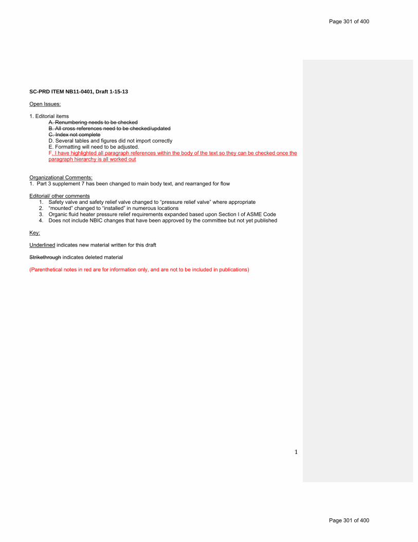
1
SC-PRD ITEM NB11-0401, Draft 1-15-13 Open Issues: 1. Editorial items A. Renumbering needs to be checked B. All cross references need to be checked/updated C. Index not complete D. Several tables and figures did not import correctly E. Formatting will need to be adjusted.
F. I have highlighted all paragraph references within the body of the text so they can be checked once the paragraph hierarchy is all worked out
Organizational Comments: 1. Part 3 supplement 7 has been changed to main body text, and rearranged for flow Editorial/ other comments
1. Safety valve and safety relief valve changed to “pressure relief valve” where appropriate 2. “mounted” changed to “installed” in numerous locations 3. Organic fluid heater pressure relief requirements expanded based upon Section I of ASME Code 4. Does not include NBIC changes that have been approved by the committee but not yet published
Key: Underlined indicates new material written for this draft Strikethrough indicates deleted material (Parenthetical notes in red are for information only, and are not to be included in publications)
Page 301 of 400
Page 301 of 400
2
NBIC PART 4
PRESSURE RELIEF DEVICES
Table of Contents INTRODUCTION Section 1: Installation of Pressure Relief Devices 1.1 INSTALLATION OF PRESSURE RELIEF DEVICES 1.2 PRESSURE RELIEF DEVICES – DEFINITIONS 1.2.1 1.4 ADDITIONAL DEFINITIONS RELATING TO PRESSUE RELIEF DEVICES 1.3 2.9 PRESSURE RELIEF VALVES FOR BOILERS 1.3.1 2.9.1 GENERAL REQUIREMENTS 1.3.2 2.9.1.1 NUMBER 1.3.3 2.9.1.2 LOCATION 1.3.4 2.9.1.3 CAPACITY
TABLE 1.3.4.1 2.9.1.3 MINIMUM POUNDS OF STEAM PER HOUR PER SQUARE FOOT OF HEATING SURFACE
1.3.5 2.9.1.4 SET PRESSURE 1.3.6 2.9.2 FORCED- FLOW STEAM GENERATORS 1.3.7 2.9.3 SUPERHEATERS 1.3.8 2.9.4 ECONOMIZERS 1.3.9 2.9.5 PRESSURE-REDUCING VALVES 1.3.10 2.9.6 INSTALLATION AND DISCHARGE REQUIREMENTS 1.3.11 2.3.1 SUPPORTS, FOUNDATIONS, AND SETTINGS 1.4 2.2.12.7 PRESSURE RELIEF VALVES FOR THERMAL FLUID HEATERS 1.5 3.9 PRESSURE RELIEF VALVES FOR HEATING BOILERS 1.5.1 3.9.1 PRESSURE RELIEF VALVE REQUIREMENTS — GENERAL 1.5.1.1 3.9.1.1 INSTALLATION OF PRESSURE RELIEF VALVES FOR HEATING BOILERS 1.5.1.1.1 3.9.1.1.1 PERMISSIBLE INSTALLATION 1.5.1.1.2 3.9.1.1.2 REQUIREMENTS FOR COMMON CONNECTIONS FOR TWO OR MORE
VALVES 1.5.1.2 3.9.1.2 THREADED CONNECTIONS 1.5.1.3 3.9.1.3 PROHIBITED INSTALLATIONS 1.5.1.4 3.9.1.4 USE OF SHUTOFF VALVES PROHIBITED 1.5.1.5 3.9.1.5 PRESSURE RELIEF VALVE DISCHARGE PIPING 1.5.1.6 3.9.1.6 TEMPERATURE AND PRESSURE RELIEF VALVES 1.5.2 3.9.2 PRESSURE RELIEF VALVE REQUIREMENTS FOR STEAM HEATING BOILERS 1.5.3 3.9.3 PRESSURE RELIEF VALVE REQUIREMENTS FOR HOT WATER HEATING OR HOT
WATER SUPPLY BOILERS 1.5.4 3.9.4 PRESSURE RELIEF VALVE REQUIREMENTS FOR POTABLE WATER HEATERS 1.5.4.13.9.4.1 INSTALLATION 1.5.4.2 3.9.4.2 PERMISSIBLE INSTALLATIONS 1.5.4.3 3.9.4.3 REQUIREMENTS FOR COMMON CONNECTION FOR TWO OR MORE VALVES 1.5.4.4 3.9.4.4 THREADED CONNECTIONS 1.5.4.5 3.9.4.5 PROHIBITED INSTALLATIONS 1.5.4.6 3.9.4.6 USE OF SHUTOFF VALVES PROHIBITED 1.5.4.7 3.9.4.7 PRESSURE RELIEF VALVE DISCHARGE PIPING 1.5.5 3.9.5 PRESSURE RELIEF VALVES FOR TANKS AND HEAT EXCHANGERS 1.5.5.1 3.9.5.1 STEAM TO HOT-WATER SUPPLY 1.5.5.2 3.9.5.2 HIGH TEMPERATURE WATER TO WATER HEAT EXCHANGER 1.5.5.3 3.9.5.3 HIGH TEMPERATURE WATER TO STEAM HEAT EXCHANGER 1.6 4.5 PRESSURE VESSEL PRESSURE RELIEF DEVICES 1.6.1 4.5.1 DEVICE REQUIREMENTS 1.6.2 4.5.2 NUMBER OF DEVICES
Page 302 of 400
Page 302 of 400
3
1.6.3 4.5.3 LOCATION 1.6.4 4.5.4 CAPACITY 1.6.5 4.5.5 SET PRESSURE 1.6.6 4.5.6 INSTALLATION AND DISCHARGE PIPING REQUIREMENTS 1.6.7 4.7.3 PRESSURE RELIEF DEVICES FOR HOT WATER STORAGE TANKS 1.7 5.3 PIPING SYSTEM PRESSURE RELIEF DEVICES 1.7.1 5.3.1 DEVICE REQUIREMENTS 1.7.2 5.3.2 NUMBER OF DEVICES 1.7.3 5.3.3 LOCATION 1.7.4 5.3.4 CAPACITY 1.7.5 5.3.5 SET PRESSURE 1.7.6 5.3.6 INLET AND DISCHARGE PIPING REQUIREMENTS SECTION 2: In-Service Inspection 2.1 2.5 IN-SERVICE INSPECTION OF PRESSURE RELIEF DEVICES 2.2 2.5.1 SCOPE 2.2.1 2.5.2 PRESSURE RELIEF DEVICE DATA 2.2.2 2.5.3 DEVICE CONDITIONS 2.2.3 2.5.4 INSTALLATION CONDITION 2.2.4 2.5.5 ADDITIONAL INSPECTION REQUIREMENTS 2.2.4.1 2.5.5.1 BOILERS 2.2.4.2 2.5.5.2 PRESSURE VESSELS AND PIPING 2.2.4.3 2.5.5.3 RUPTURE DISKS 2.2.5 2.5.7 TESTING AND OPERATIONAL INSPECTION OF PRESSURE RELIEF DEVICES 2.2.5.1 CORRECTIVE ACTION 2.2.5.2 VALVE ADJUSTMENTS 2.2.6 2.5.8 RECOMMENDED INSPECTION AND TEST FREQUENCIES FOR PRESSURE RELIEF
DEVICES 2.2.6.1 G) ESTABLISHMENT OF INSPECTION AND TEST INTERVALS 2.2.6.2 H) ESTABLISHMENT OF SERVICE INTERVALS Section 3: Repair 3.1 S7.1 REPAIR OF PRESSURE RELIEF DEVICES, SCOPE 3.2 S7.2 GENERAL REQUIREMENTS 3.2.1 S7.2 d) VR REPAIR 3.2.2 1.2 d) CONSTRUCTION STANDARDS FOR PRESSURE RELIEF DEVICES 3.2.3 INSTALLATION OF PRESSURE RELIEF DEVICES 3.2.4 S7.6 INITIAL ADJUSTMENTS TO PRESSURE RELIEF VALVES 3.3 S7.4 MATERIALS FOR PRESSURE RELIEF VALVE REPAIR 3.3.1 S7.5 REPLACEMENT PARTS FOR PRESSURE RELIEF DEVICES 3.4 S7.12 WELDING FOR PRESSURE RELIEF VALVES 3.4.1 S7.12.1 WELDING PROCEDURE SPECIFICATIONS 3.4.2 S7.12.2 STANDARD WELDING PROCEDURE SPECIFICATIONS 3.4.3 S7.12.3 PERFORMANCE QUALIFICATION 3.4.4 S7.12.4 WELDING RECORDS 3.4.5 S7.12.5 WELDERS’ IDENTIFICATION 3.4.6 S7.12.6 WELDERS’ CONTINUITY 3.4.7 S7.3 WELD REPAIRS TO PRESSURE RELIEF VALVE PARTS BY AN “R” STAMP HOLDER 3.5 S7.13 HEAT TREATMENT 3.5.1 S7.13.1 PREHEATING 3.5.2 S7.13.2 POSTWELD HEAT TREATMENT 3.6 4.5 PRESSURE RELIEF VALVE PERFORMANCE TESTING AND TESTING EQUIPMENT 3.6.1 4.5.1 TEST MEDIUM AND TESTING EQUIPMENT 3.6.2 4.5.2 OWNER-USER ASME CODE SECTION VIII STEAM TESTING 3.6.3 4.5.3 LIFT ASSIST TESTING 3.6.4 4.5.4 PRESSURE TEST OF PARTS
Page 303 of 400
Page 303 of 400
4
3.7 5.12 STAMPING REQUIREMENTS FOR PRESSURE RELIEF DEVICES 3.7.1 5.12.1 NAMEPLATES 3.7.2 5.12.2 REPAIR NAMEPLATE Figure 3.7.2-a Figure 5.7.5-e REQUIRED MARKINGS FOR REPAIR OF ASME/NATIONAL BOARD "V,
"UV," AND "HV" -STAMPED PRESSURE RELIEF VALVES Figure 3.7.2-b Figure 5.7.5-g REQUIRED MARKINGS FOR REPAIR OR REPLACEMENT OF NUCLEAR
PRESSURE RELIEF VALVES 3.7.3 5.12.3 CHANGES TO ORIGINAL PRESSURE RELIEF VALVE NAMEPLATE INFORMATION 3.7.4 5.12.4 TEST ONLY NAMEPLATE 3.7.5 5.12.5 REPLACEMENT OF ILLEGIBLE OR MISSING NAMEPLATES 3.8 1.7 ACCREDITATION OF “VR” REPAIR ORGANIZATIONS 3.8.1 1.7.1 SCOPE 3.8.2 .7.2 JURISDICTIONAL PARTICIPATION 3.8.3 1.7.3 ISSUANCE AND RENEWAL OF THE “VR” CERTIFICATE OF AUTHORIZATION 3.8.3.1 1.7.3.1 GENERAL 3.8.3.2 1.7.3.2 ISSUANCE OF CERTIFICATE 3.8.4 1.7.4 USE OF THE “VR” AUTHORIZATION 3.8.4.1 1.7.4.1 TECHNICAL REQUIREMENTS 3.8.4.2 1.7.4.2 STAMP USE 3.8.5 1.7.5 QUALITY SYSTEM 3.8.5.1 1.7.5.1 GENERAL 3.8.5.2 1.7.5.2 WRITTEN DESCRIPTION 3.8.5.3 1.7.5.3 MAINTENANCE OF CONTROLLED COPY 3.8.5.4 1.7.5.4 OUTLINE OF REQUIREMENTS FOR A QUALITY SYSTEM 3.8.6 S7.7 FIELD REPAIR 3.8.6.1 S7.8 AUDIT REQUIREMENTS 3.8.6.2 S7.9 USE OF OWNER-USER PERSONNEL 3.9 S7.11 TRAINING AND QUALIFICATION OF PERSONNEL 3.9.1 S7.11.2 CONTENTS OF TRAINING PROGRAM 3.9.2 S7.11.3 QUALIFICATION OF PERSONNEL 3.9.3 S7.11.4 ANNUAL REVIEW OF QUALIFICATION Supplement 1: Pressure Relief Valves On The Low Pressure Side Of Steam Pressure-Reducing Valves S1.1 S2.1 SCOPE S1.2 S2.2 SAFETY VALVE CAPACITY S1.3 S2.3 CALCULATION OF SAFETY VALVE RELIEVING CAPACITY Table S1.3-a S2.3-a CAPACITY OF SATURATED STEAM, IN LB./HR., PER SQ. IN. OF PIPE AREA Table S1.3M-a S2.3M-a CAPACITY OF SATURATED STEAM, IN KG/HR., PER SQ. MM OF PIPE AREA Table S1.3-b S2.3-b CAPACITY OF SATURATED STEAM, IN LB./HR., PER SQ. IN. OF PIPE AREA Table S1.3M-b S2.3M-b CAPACITY OF SATURATED STEAM, IN KG/HR., PER SQ. MM OF PIPE AREA Table S1.3-c S2.3-c CAPACITY OF SATURATED STEAM, IN LB./HR., PER SQ. IN. OF PIPE AREA Table S1.3M-c S2.3M-c CAPACITY OF SATURATED STEAM, IN KG/HR., PER SQ. MM OF PIPE AREA S1.4 S2.4 STEAM FLOW WHEN FLOW COEFFICIENTS ARE NOT KNOWN S1.5 S2.5 TWO-STAGE PRESSURE-REDUCING VALVE STATIONS Supplement 2: Pressure Differential Between Safety Or Safety Relief Valve Setting And Boiler Or Pressure Vessel Operating Pressure S2.1 S8.1 SCOPE S2.2 S8.2 HOT WATER HEATING BOILERS S2.3 S8.3 STEAM HEATING BOILERS S2.4 S8.4 POWER BOILERS S2.5 S8.5 PRESSURE VESSELS Supplement 3 S7.10: Guide To Jurisdictions For Authorization Of Owners-Users To Make Adjustments To Pressure Relief Valves
Page 304 of 400
Page 304 of 400
5
S3.1 S7.10.1 GENERAL S3.2 S7.10.2 TRAINING S3.3 S7.10.3 DOCUMENTATION S3.4 S7.10.4 QUALITY SYSTEM S3.5 S7.10.5 EXTERNAL ADJUSTMENTS S3.6 S7.10.6 REPAIRS Supplement 4: Recommended Procedures For Repairing Pressure Relief Valves S4.1 S7.14.1 INTRODUCTION S4.2 S7.14.2 SPRING-LOADED PRESSURE RELIEF VALVES S4.3 S7.14.3 PILOT OPERATED SAFETY RELIEF VALVES S4.4 2.5.6 PACKAGING, SHIPPING AND TRANSPORTATION OF PRESSURE RELIEF DEVICES Supplement 5 Supplement 8: Recommended Guide For The Design Of A Test System For Pressure Relief Devices In Compressible Fluid Service S5.1 S8.1 INTRODUCTION S5.2 S8.2 GENERAL S5.3 S8.3 TEST SYSTEM DESCRIPTION Figure S5.3-a S8.3-a SCHEMATIC OF TEST EQUIPMENT WITH ACCUMULATOR Figure S5.3-b S8.3-b SCHEMATIC OF TEST EQUIPMENT WITHOUT ACCUMULATOR S5.4 S8.4 TEST VESSEL SIZING DATA Figure S5.4-a S8.4-a RECOMMENDED TEST VESSEL SIZE, TEST MEDIUM: STEAM Figure S5.4-b S8.4-b RECOMMENDED TEST VESSEL SIZE, TEST MEDIUM: AIR OR GAS Supplement 6 Supplement 9: Procedures To Extend The “Vr” Certificate Of Authorization And Stamp To Asme “Nv” Stamped Pressure Relief Devices S6.1 S9.1 INTRODUCTION S6.2 S9.2 ADMINISTRATIVE PROCEDURES S6.3 S9.3 GENERAL RULES Section 4 Section 7 Installation –: NBIC Policy For Metrication 4.1 7.1 GENERAL 4.2 7.2 EQUIVALENT RATIONALE 4.3 7.3 PROCEDURE FOR CONVERSION 4.4 7.4 REFERENCING TABLES Table 4.4-1 7.4-1 SOFT CONVERSION FACTORS (US X FACTOR = METRIC) Table 4.4-2 7.4-2 TEMPERATURE EQUIVALENTS Table 4-4-3 7.4-3 US FRACTIONS/METRIC EQUIVALENTS Table 4.4-4 7.4-4 PIPE SIZES/EQUIVALENTS Table 4.4-5a 7.4-5a “” Table 4.4-5b 7.4-5b “” Table 4.4-6a 7.4-6a “” Table 4.4-6b 7.4-6b “” Table 4.4-7 7.4-7 PRESSURE/EQUIVALENTS Table 4.4-8 7.4-8 “” Section 5 Section 8: PRESSURE RELIEF DEVICES — Preparation Of Technical Inquiries To The National Board Inspection Code Committee 5.1 8.0 INTRODUCTION 5.2 8.2 INQUIRY FORMAT 5.3 8.3 CODE REVISIONS OR ADDITIONS 5.4 8.4 CODE INTERPRETATIONS 5.5 8.5 SUBMITTAL
Page 305 of 400
Page 305 of 400
6
Section 6 Section 9: Pressure Relief Devices – Glossary of Terms 6.1 9.1 DEFINITIONS Section 7: Pressure Relief Devices – NBIC- Approved Interpretations
Page 306 of 400
Page 306 of 400
7
PART 4, SECTION 1 Installation of Pressure Relief Devices (previously in Part 1) 1.1 INSTALLATION OF PRESSURE RELIEF DEVICES The correct selection of appropriate pressure relief devices (PRDs) and the proper installation of those devices are critical to the safe operation of pressure retaining Items. Following are requirements for the installation of pressure relief devices for protection of different types of pressurized equipment. See NBIC Part 1 for general installation requirements. 1.2 PRESSURE RELIEF DEVICES — DEFINITIONS a) Pressure Relief Device: A device designed to prevent pressure or vacuum from exceeding a predetermined value in a pressure vessel by the transfer of fluid during emergency or abnormal conditions.
b) Pressure Relief Valve (PRV): A pressure relief device designed to actuate on inlet static pressure and reclose after normal conditions have been restored.
c) Safety valve: A pressure relief valve characterized by rapid opening and normally used to relieve compressible fluids.
d) Safety relief valve: A pressure relief valve characterized by rapid opening or by gradual opening that is generally proportional to the increase in pressure. It can be used for compressible or incompressible fluids.
e) Relief valve; A pressure relief valve characterized by gradual opening that is generally proportional to the increase in pressure. It is normally used for incompressible fluids.
f) Pilot operated pressure relief valve: A pressure relief valve in which the disk is held closed by system pressure, and the holding pressure is controlled by a pilot valve actuated by system pressure. 1.2.1 Part 3, 1.4 ADDITIONAL DEFINITIONS RELATING TO PRESSURE RELIEF DEVICES Unless otherwise specified in these rules and procedures, the definitions relating to pressure relief devices in Section 2 of ASME PTC25 shall apply. 1.3 2.9 PRESSURE RELIEF VALVES FOR POWER BOILERS See NBIC Part 1, par. 2.2 for the boilers covered under this section. 1.3.1 2.9.1 GENERAL REQUIREMENTS a) Safety valves are designed to relieve steam. Only direct spring loaded safety valves, direct spring loaded safety relief valves, or pilot operated pressure relief valves designed to relieve steam shall be used for steam service.
b) Safety relief valves are valves designed to relieve either steam or water, depending on the application.
c) Safety and safety relief Pressure relief valves are toshall be manufactured in accordance with a national or international standard.
d) Deadweight or weighted-lever pressure reliefving valves shall not be used.
e) For high temperature water boilers, pressure safety relief valves shall have a closed bonnet, and safety relief valve bodies shall not be constructed of cast iron.
Comment [BB1]: ShoulddefinitionsjustgointheglossaryatthebackofthebooklikeinParts1,2and3?
Comment [BB2]: Doweevenneedthesedefinitionsifwearenotusingthisterminologyanymore?
Comment [BB3]: Thereisanopenactionitem(NB10‐1201)thatisworkingtocombinecommoninstallationrequirementsintoasinglesection,sothatrequirementsthatarethesameforpowerboilers,heatingboilers,andpressurevesselsdonotneedtoberepeated3times.ThisshouldbeconsideredinPart4.
Comment [BB4]: Shouldthisberemovedfrom“requirements”andinsteadbeplacedwiththedefinition?
Comment [BB5]: UseNBIClanguage
Page 307 of 400
Page 307 of 400

8
f) Safety and safety relief Pressure relief valves with an inlet connection greater than NPS 3 (DN 80) and used for pressure greater than 15 psig (1003 kPa), shall have a flanged inlet connection or a welding-end inlet connection. The dimensions of flanges subjected to boiler pressure shall conform to the applicable standards.
g) When a safety or safety pressure relief valve is exposed to outdoor elements that may affect operation of the valve, it is permissible to shield the valvethe valve may be shielded with a cover. The cover shall be properly vented and arranged to permit servicing and normal operation of the valve. 1.3.2 2.9.1.1 NUMBER At least one National Board capacity certified pressure safety or safety relief valve shall be installed on the boiler. If the boiler has more than 500 sq. ft. (46 sq. m.) of heating surface, or if an electric boiler has a power input of more than 3.76 million BTU/hr (1100 kW), two or more National Board capacity certified pressure safety or safety relief valves shall be installed. 1.3.3 2.9.1.2 LOCATION a) Pressure Safety or safety relief valves shall be placed on, or as close as physically possible, to the boiler proper.
b) Pressure Safety or safety relief valves shall not be placed on the feedline.
c) Pressure Safety or safety relief valves shall be connected to the boiler independent of any other connection without any unnecessary intervening pipe or fittings. Such intervening pipe or fittings shall not be longer than the face-to-face dimension of the corresponding tee fitting of the same diameter and pressure rating as listed in the applicable standards. 1.3.4 2.9.1.3 CAPACITY a) The pressure-relieving valve capacity for each boiler shall be such that the valve or valves will discharge all the steam that can be generated by the boiler without allowing the pressure to rise more than 6% above the highest pressure at which any valve is set and in no case to more than 6% above the maximum allowable working pressure of the boiler.
b) The minimum relieving capacity for other than electric boilers and forced-flow steam generators with no fixed steam line and waterline shall be estimated for the boiler and waterwall heating surfaces as given in Table 1.3.4.1 2.9.1.3, but in no case should the minimum relieving capacity be less than the maximum designed steaming capacity as determined by the manufacturer.
c) The required relieving capacity in lbs/hr of the pressure safety or safety relief valves on a high temperature water boiler shall be determined by dividing the maximum output in Btu at the boiler nozzle obtained by the firing of any fuel for which the unit is designed by one thousand.
d) The minimum pressure safety or safety relief valve relieving capacity for electric boilers is shall not be less than 3.5 lbs/hr/kW (1.6 kg/hr/kW) input.
e) If the pressure safety or safety relief valve capacity cannot be computed, or if it is desirable to prove the computations, it should be checked by any one of the following methods; and if found insufficient, additional relieving capacity shall be provided:
1) By performing an accumulation test, that is, by shutting off all other steam discharge outlets from the boiler and forcing the fires to the maximum. This method should not be used on a boiler with a superheater or reheater or on a high-temperature water boiler.
2) By measuring the maximum amount of fuel that can be burned and computing the corresponding evaporative capacity upon the basis of the heating value of the fuel.
Comment [BB6]: Doweneedtocalloutgagepressureeverytime,orcanwejustsay“psi”?
Comment [BB7]: UseNBIClanguage
Comment [BB8]: Thisseemslikea“shall”requirement?
Comment [BB9]: NBIClanguage
Comment [BB10]: Shall?
Page 308 of 400
Page 308 of 400
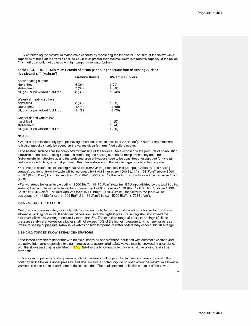
9
3) By determining the maximum evaporative capacity by measuring the feedwater. The sum of the safety valve capacities marked on the valves shall be equal to or greater than the maximum evaporative capacity of the boiler. This method should not be used on high-temperature water boilers. Table 1.3.4.1 2.9.1.3 - Minimum Pounds of steam per hour per square foot of Heating Surface lbs steam/hr/ft2 (kg/hr/m2) Firetube Boilers Watertube Boilers Boiler heating surface Hand-fired 5 (24) 6(29) stoker-fired 7 (34) 8 (39) oil, gas, or pulverized fuel-fired 8 (39) 10 (49) Waterwall heating surface hand-fired 8 (39) 8 (39) stoker-fired 10 (49) 12 (59) oil, gas, or pulverized fuel-fired 14 (68) 16 (78) Copper-finned watertubes hand-fired 4 (20) stoker-fired 5 (24) oil, gas, or pulverized fuel-fired 6 (29) NOTES:
• When a boiler is fired only by a gas having a heat value not in excess of 200 Btu/ft3(7.5MJ/m3), the minimum relieving capacity should be based on the values given for hand-fired boilers above.
• The heating surface shall be computed for that side of the boiler surface exposed to the products of combustion, exclusive of the superheating surface. In computing the heating surface for this purpose only the tubes, fireboxes,shells, tubesheets, and the projected area of headers need to be considered, except that for vertical firetube steam boilers, only that portion of the tube surface up to the middle gage cock is to be computed.
• For firetube boiler units exceeding 8000 Btu/ft2 (9085 J/cm2) (total fuel Btu (J) Input divided by total heating surface), the factor from the table will be increased by 1 (4.88) for every 1000 Btu/ft.2 (1136 J/cm2) above 8000 Btu/ft.2 (9085 J/cm2) For units less than 7000 Btu/ft2 (7950 J/cm2), the factor from the table will be decreased by 1 (4.88).
• For watertube boiler units exceeding 16000 Btu/ft2 (18170 J/cm2)(total fuel BTU input divided by the total heating surface) the factor from the table will be increased by 1 (4.88) for every 1000 Btu/ft.2 (1136 J/cm2) above 16000 Btu/ft.2 (18170 J/cm2). For units with less than 15000 Btu/ft.2 (17034 J/cm2), the factor in the table will be decreased by 1 (4.88) for every 1000 Btu/ft.2 (1136 J/cm2) below 15000 Btu/ft.2 (17034 J/cm2). 1.3.5 2.9.1.4 SET PRESSURE One or more pressure safety or safety relief valves on the boiler proper shall be set at or below the maximum allowable working pressure. If additional valves are used, the highest pressure setting shall not exceed the maximum allowable working pressure by more than 3%. The complete range of pressure settings of all the pressure safety relief valves on a boiler shall not exceed 10% of the highest pressure to which any valve is set. Pressure setting of pressure safety relief valves on high temperature water boilers may exceed this 10% range. 1.3.6 2.9.2 FORCED-FLOW STEAM GENERATORS For a forced-flow steam generator with no fixed steamline and waterline, equipped with automatic controls and protective interlocks responsive to steam pressure, pressure relief safety valves may be provided in accordance with the above paragraphs identified in 1.3.5 2.9.1 or the following protection against overpressure shall be provided: a) One or more power-actuated pressure reliefving valves shall be provided in direct communication with the boiler when the boiler is under pressure and shall receive a control impulse to open when the maximum allowable working pressure at the superheater outlet is exceeded. The total combined relieving capacity of the power
Page 309 of 400
Page 309 of 400
10
actuated pressure reliefving valves shall be not less than 10% of the maximum design steaming capacity of the boiler under any operating condition as determined by the manufacturer. The valves shall be located in the pressure part system where they will relieve the overpressure. An isolating stop valve of the outside-screw-and-yoke type should be installed between the power actuated pressure-relieving valve and the boiler to permit repairs provided an alternate power-actuated pressure reliefving valve of the same capacity is so installed as to be in direct communication with the boiler.
b) Pressure relief valves shall be provided having a total combined relieving capacity, including that of the power-actuated pressure reliefving valve, of not less than 100% of the maximum designed steaming capacity of the boiler, as determined by the manufacturer. In this total, credit in excess of 30% of the total relieving capacity shall not be allowed for the power-actuated pressure reliefving valves actually installed. Any or all of the pressure relief valves may be set above the maximum allowable working pressure of the parts to which they are connected, but the set pressures shall be such that when all these valves (together with the power-actuated pressure reliefving valves) are in operation the pressure will not rise more than 20% above the maximum allowable working pressure of any part of the boiler, except for the steam piping between the boiler and the prime mover.
c) When stop valves are installed in the water steam flow path between any two sections of a forced-flow steam generator with no fixed steamline and waterline:
1) The power-actuated pressure-relieving valve shall also receive a control impulse to open when the maximum allowable working pressure of the component, having the lowest pressure level upstream to the stop valve, is exceeded.
2) The pressure relief valve shall be located to provide overpressure protection for the component having the lowest working pressure.
3) A reliable pressure-recording device shall always be in service and records kept to provide evidence of conformity to the above requirements. 1.3.7 2.9.3 SUPERHEATERS a) Every attached superheater shall have one or more safety pressure relief valves. The location shall be suitable for the service intended and shall provide the overpressure protection required. The pressure drop upstream of each safety pressure relief valve shall be considered in determining the set pressure and relieving capacity of that valve. If the superheater outlet header has a full, free steam passage from end to end and is so constructed that steam is supplied to it at practically equal intervals throughout its length so that there is a uniform flow of steam through the superheater tubes and the header, the safety pressure relief valve or valves may be located anywhere in the length of header.
b) The pressure-relieving capacity of the safety pressure relief valve or valves on an attached superheater shall be included in determining the number and size of the safety valves for the boiler provided there are no intervening valves between the superheater safety pressure relief valve and the boiler and the discharge capacity of the pressure safety relief valve or valves, on the boiler, as distinct from the superheater, is at least 75% of the aggregate capacity required.
c) Every independently fired superheater that may be shut off from the boiler and permit the superheater to become a fired pressure vessel shall have one or more safety pressure relief valves having a discharge capacity equal to 6 lbs steam/hr/ft2 (29 kg steam/hr/m2) of superheater surface measured on the side exposed to the hot gases.
d) Every safety pressure relief valve used on a superheater discharging superheated steam at a temperature over 450°F (230°C) shall have a casing, including the base, body, bonnet, and spindle constructed of steel, steel alloy, or equivalent heat-resistant material. The valve shall have a flanged inlet connection or a welding-end inlet connection. The seat and disk shall be constructed of suitable heat-erosive and corrosive-resistant material, and the spring fully exposed outside of the valve casing so that it is protected from contact with the escaping steam.
1.3.8 2.9.4 ECONOMIZERS
Page 310 of 400
Page 310 of 400
11
An economizer that may not be isolated from a boiler does not require a pressure safety relief valve. Economizers that may be isolated from a boiler or other heat transfer device, allowing the economizer to become a fired pressure vessel, shall have a minimum of one pressure relief valve. Discharge capacity, rated in lbs/hr (kg/hr), of the pressure safety relief valve or valves shall be calculated from the maximum expected heat absorption rate in Btu/hr (kJoules/hr) of the economizer, and will be determined from manufacturer data, divided by 1000 (2326). The pressure safety relief valve shall be located as close as possible to the economizer outlet. 1.3.9 2.9.5 PRESSURE-REDUCING VALVES a) Where pressure-reducing valves are used, one or more pressure safety or safety relief valves shall be installed on the low pressure side of the reducing valve in those installations where the piping or equipment on the low pressure side does not meet the requirements for the steam supply piping.
b) The pressure safety or safety relief valves shall be located as close as possible to the pressure reducing valve.
c) Capacity of the pressure safety or safety relief valves shall not be less than the total amount of steam that can pass from the high pressure side to the low pressure side and be such that the pressure rating of the lower pressure piping or equipment shall not be exceeded.
d) The use of hand-controlled bypasses around reducing valves is permissible. The bypass around a reducing valve may not be greater in capacity than the reducing valve unless the piping or equipment is adequately protected by pressure safety or safety relief valves or meets the requirements of the high pressure system.
e) See NBIC Part 4, Supplement 1 for additional information on the calculation of the required capacity of pressure relief valves installed after pressure-reducing valves. 1.3.10 2.9.6 INSTALLATION MOUNTING AND DISCHARGE REQUIREMENTS a) Every boiler shall have outlet connections for the pressure safety or safety relief valve, or valves, independent of any other outside steam connection, the area of opening shall be at least equal to the aggregate areas of inlet connections of all of the attached pressure safety or safety relief valves. An internal collecting pipe, splash plate, or pan should be used, provided the total area for inlet of steam thereto is not less than twice the aggregate areas of the inlet connections of the attached pressure safety or safety relief valves. The holes in such collecting pipes shall be at least 1/4 in. (6 mm) in diameter, and the least dimension in any other form of opening for inlet of steam shall be 1/4 in. (6 mm). If pressure safety or safety relief valves are attached to a separate steam drum or dome, the opening between the boiler proper and the steam drum or dome shall be not less than 10 times the total area of the safety valve inlet.
b) Every pressure safety or safety relief valve shall be connected so as to stand in an upright position with spindle vertical.
c) The opening or connection between the boiler and the pressure safety or safety relief valve shall have at least the area of the valve inlet and the inlet pipe to the pressure relief valve shall be no longer than the face to face dimension of the corresponding tee fitting of the same diameter and pressure class. When a discharge pipe is used, the cross-sectional area shall not be less than the full area of the valve outlet or of the total of the areas of the valve outlets, discharging there into and shall be as short and straight as possible and arranged to avoid undue stresses on the valve or valves.
d) No valve of any description except a changeover valve as defined below, shall be placed between the pressure safety or safety relief valves and the boiler, nor on the discharge pipe between the pressure safety or safety relief valves and the atmosphere.
A changeover valve, which allows two redundant pressure relief valves to be installed for the purpose of changing from one pressure relief valve to the other while the boiler is operating, may be used provided the changeover valve is in accordance with the original code of construction. It is recommended that the Jurisdiction be contacted to determine the acceptability of the changeover valves on boiler applications. The changeover valve shall be designed such that there is no intermediate position where both pressure relief valves are isolated form the boiler.
Comment [BB11]: Needsmetricconversion–Ithinkthisisright,butshouldbechecked–Ifoundthisconversionfactorlaterinthe2013NBIC,butmycalculationsgetsomethingdifferent
Page 311 of 400
Page 311 of 400
12
e) When two or more pressure safety relief valves are used on a boiler, they should be mounted either separately or as twin valves made by placing individual valves on Y-bases, or duplex valves having two valves in the same body casing. Twin valves made by placing individual valves on Y-bases or duplex valves having two valves in the same body shall be of equal size.
f) When two valves of different sizes are installed mounted singly, the relieving capacity of the smaller valve shall not be less than 50% of that of the larger valve.
g) When a boiler is fitted with two or more pressure safety relief valves on one connection, this connection to the boiler shall have a cross-sectional area not less than the combined areas of inlet connections of all the pressure safety relief valves with which it connects.
h) All pressure safety or safety relief valves shall be piped to a safe point of discharge so located or piped as to be carried clear from running boards or platforms. Provision for an ample gravity drain shall be made in the discharge pipe at or near each pressure safety or safety relief valve, and where water or condensation may collect. Each valve shall have an open gravity drain through the casing below the level of the valve seat. For iron- and steel- bodied valves exceeding NPS 2 (DN 50), the drain hole shall be tapped not less than NPS 3/8 (DN 10).
i) Discharge piping from pressure safety relief valves on high temperature water boilers shall have adequate provisions for water drainage as well as steam venting.
j) If a muffler is used on a pressure safety or safety relief valve, it shall have sufficient outlet area to prevent back pressure from interfering with the proper operation and discharge capacity of the valve. The muffler plates or other devices shall be so constructed as to avoid a possibility of restriction of the steam passages due to deposits. Mufflers shall not be used on high temperature water boiler pressure relief valves. 1.3.11 2.3.1 SUPPORTS, FOUNDATIONS, AND SETTINGS Each boiler pressure relief valve and its associated piping must be safely supported. Design of supports, foundations, and settings shall consider vibration (including seismic where necessary), movement (including thermal movement), and loadings (including reaction forces the weight of water during a hydrostatic test) in accordance with jurisdictional requirements, manufacturer’s recommendations, and/or other industry standards, as applicable. 1.4 PART 2, 2.2.12.7.f. PRESSURE RELIEF VALVES FOR THERMAL FLUID HEATERS a) Pressure Relief Valves — Pressure relief valves shall be a closed bonnet design with no manual lift lever. A valve body drain is not required. The pressure relief discharge should be connected to a closed, vented storage tank or blowdown tank with solid piping (no drip pan elbow, or other air gap). When outdoor discharge is used, the following should be considered for discharge piping at the point of discharge: 1) Both thermal and chemical reactions (personnel hazard)
2) Combustible materials (fire hazard)
3) Surface drains (pollution and fire hazard)
4) Loop seal or rain cap on the discharge (keep both air and water out of the system)
5) Drip leg near device (prevent liquid collection)
6) Heat tracing for systems using high freeze point fluids (prevent blockage)
(The following was developed based upon ASME Code Section I, Part PVG) 7) A suitable condenser that will condense all the vapors discharged from the pressure relief valve may be used in lieu of piping the vapors to the atmosphere.
Page 312 of 400
Page 312 of 400
13
8) In order to minimize the loss by leakage of material through the pressure relief valve, a rupture disk may be installed between the pressure relief valve and the vaporizer, provided the following requirements are met:
a. The cross‐sectional area of the connection to a vaporizer shall be not less than the required relief area of the rupture disk.
b. The maximum pressure of the range for which the disk is designed to rupture does shall not exceed the opening pressure for which the pressure relief valve is set or the maximum allowable working pressure of the vessel.
c. The opening provided through the rupture disk, after breakage, is shall be sufficient to permit a flow equal to the capacity of the attached valve, and there is no chance of interference with the proper functioning of the valve, but in no case shall this area be less than the inlet area of the valve.
d. The space between a rupture disk and the valve should be provided with a pressure gage, try cock, free vent, or a suitable telltale indicator. This arrangement permits the detection of disk rupture or leakage.
e. Pressure relief valve discharge capacity shall be determined from the following equation: W = CKAP √(M/T) Where A = discharge area of pressure relief valve C = constant for vapor that is a function of the ratio of Specific Heats k = cp/cv . Note: Where k is not known, k = 1.001. K = coefficient of discharge for the valve design M = molecular weight P = (set pressure × 1.03) + Atmosphere Pressure T = absolute temperature at inlet, °F + 460 (°C + 273) W = flow of vapor The required minimum pressure relief valve relieving capacity shall be determined from the following equation: W= C x H x 0.75/h where C = maximum total weight or volume of fuel burned per hour, lb (kg) or ft3 (m3) H = heat of combustion of fuel, Btu/lb (J/kg) or Btu/ft3 (J/m3) h = latent heat of heat transfer fluid at relieving pressure, Btu/lb (J/kg) W = weight of organic fluid vapor generated per hour The sum of the pressure relief valve capacities marked on the valves shall be equal to or greater than W. 1.5 3.9 PRESSURE RELIEF VALVES FOR HEATING BOILERS See NBIC Part 1, 3.2 for the scope of pressure retaining items covered by these requirements. 1.5.1 3.9.1 PRESSURE RELIEF SAFETY VALVE REQUIREMENTS — GENERAL The following general requirements pertain to the installation of mounting, and connecting pressure relief safety valves on heating boilers. 1.5.1.1 3.9.1.1 INSTALLATION OF MOUNTING PRESSURE RELIEF SAFETY AND SAFETY RELIEF VALVES FOR HEATING BOILERS 1.5.1.1.1 3.9.1.1.1 PERMISSIBLE INSTALLATION MOUNTING
Comment [BB12]: NBIClanguage
Comment [BB13]: NBIClanguage
Comment [BB14]: Shall?
Comment [BB15]: Thesetwoadditionsaregood,butcomeinalistof“considerations”,notrequirements.Theseshouldbeputintheirownparagraphstosupplementthelistof“considerations”
Page 313 of 400
Page 313 of 400
14
Pressure Safety valves and safety relief valves shall be located at the top side of the boiler. The top side of the boiler shall mean the highest practicable part of the boiler proper but in no case shall the safety valves be located below the normal operating level and in no case shall the safety relief valve be located below the lowest permissible water level. They shall be connected directly to a tapped or flanged opening in the boiler, to a fitting connected to the boiler by a short nipple, to a Y-base, or to a valveless header connecting steam or water outlets on the same boiler. Coil or header type boilers shall have the safety valve or safety pressure relief valve located on the steam or hot water outlet end. Safety valves and safety Pressure relief valves shall be installed with their spindles vertical. The opening or connection between the boiler and any safety valve or safety relief valve shall have at least the area of the valve inlet. 1.5.1.1.2 3.9.1.1.2 REQUIREMENTS FOR COMMON CONNECTIONS FOR TWO OR MORE VALVES a) When a boiler is fitted with two or more safety pressure relief valves on one connection, this connection shall have a cross-sectional area not less than the combined areas of inlet connections of all the safety pressure relief valves with which it connects. b) When a Y-base is used, the inlet area shall be not less than the combined outlet areas. When the size of the boiler requires a safety valve or safety pressure relief valve larger than NPS -4 (DN 100), two or more valves having the required combined capacity shall be used. When two or more valves are used on a boiler, they may be single, directly attached, or installed mounted on a Y-base. 1.5.1.2 3.9.1.2 THREADED CONNECTIONS A threaded connection may be used for attaching a valve. 1.5.1.3 3.9.1.3 PROHIBITED INSTALLATIONS MOUNTINGS Pressure relief Safety and safety relief valves shall not be connected to an internal pipe in the boiler. 1.5.1.4 3.9.1.4 USE OF SHUTOFF VALVES PROHIBITED No shutoff valve of any description shall be placed between the safety or safety pressure relief valve and the boiler or on discharge pipes between such valves and the atmosphere. 1.5.1.5 3.9.1.5 PRESSURE RELIEF SAFETY AND SAFETY RELIEF VALVE DISCHARGE PIPING a) A discharge pipe shall be used. Its internal cross-sectional area shall be not less than the full area of the valve outlet or of the total of the valve outlets that discharge into the pipe, and shall be as short and straight as possible and so arranged as to avoid undue stress on the valve or valves. A union may be installed in the discharge piping close to the valve outlet. When an elbow is placed on a safety or a safety pressure relief valve discharge pipe, it shall be located close to the valve outlet downstream of the union to minimize reaction moment stress.
b) The discharge from safety or a safety pressure relief valves shall be so arranged that there will be no danger of scalding attendants. The safety or a safety pressure relief valve discharge shall be piped away from the boiler to a safe point of discharge, and there shall be provisions made for properly draining the piping. The size and arrangement of discharge piping shall be such that any pressure that may exist or develop will not reduce the relieving capacity of the relieving devices below that required to protect the boiler. 1.5.1.6 3.9.1.6 TEMPERATURE AND PRESSURE SAFETY RELIEF VALVES Hot-water heating or supply boilers limited to a water temperature of 210°F (99°C) may have one or more National Board capacity certified temperature and pressure safety relief valves installed. The requirements of 1.5.1.1 3.9.1.1 through 1.5.1.5 3.9.1.5 shall be met, except as follows: a) A Y-type fitting shall not be used.
b) If additional valves are used, they shall be temperature and pressure safety relief valves.
Comment [BB16]: Couldn’tallofthisbelumpedunderonesectionheading
Page 314 of 400
Page 314 of 400
15
c) When the temperature and pressure safety relief valve is installed mounted directly on the boiler with no more than 4 in. (100 mm) maximum interconnecting piping, the valve may should be installed in the horizontal position with the outlet pointed down. 1.5.2 3.9.2 SAFETY PRESSURE RELIEF VALVE REQUIREMENTS FOR STEAM HEATING BOILERS a) Safety Pressure relief valves are toshall be manufactured in accordance with a national or international standard.
b) Each steam boiler shall have one or more National Board capacity certified safety pressure relief valves of the spring pop type adjusted and sealed to discharge at a pressure not to exceed 15 psig (100 kPa).
c) No safety pressure relief valve for a steam boiler shall be smaller than NPS 1/2 (DN 15). No safety pressure relief valve shall be larger than NPS 4 (DN 100). The inlet opening shall have an inside diameter equal to, or greater than, the seat diameter.
d) The minimum valve capacity in lbs/hr (kg/hr) shall be the greater of that determined by dividing the maximum Btu/hr (Watts) output at the boiler nozzle obtained by the firing of any fuel for which the unit is installed by 1000 Btu/hr/lb (645 W/kg), or shall be determined on the basis of the lbs steam/hr/ft2 (kg steam/hr/m2) of boiler heating surface as given in Table 1.3.4.1 3.9.2. For cast-iron boilers, the minimum valve capacity shall be determined by the maximum output method. In many cases a greater relieving capacity of valves will have to be provided than the minimum specified by these rules. In every case, the requirement of 1.5.2 e) 3.9.2e)shall be met.
e) The safety pressure relief valve capacity for each steam boiler shall be such that with the fuel burning equipment installed, and operated at maximum capacity, the pressure cannot rise more than 5 psig (34 kPa) above the maximum allowable working pressure.
f) When operating conditions are changed, or additional boiler heating surface is installed, the valve capacity shall be increased, if necessary, to meet the new conditions and be in accordance with 1.5.2 e) 3.9.2e).The additional valves required, on account of changed conditions, may be installed on the outlet piping provided there is no intervening valve. 1.5.3 3.9.3 SAFETY PRESSURE RELIEF VALVE REQUIREMENTS FOR HOT WATER HEATING OR HOT WATER SUPPLY BOILERS a) Safety Pressure relief valves are toshall be manufactured in accordance with a national or international standard.
b) Each hot-water heating or hot-water supply boiler shall have at least one National Board capacity certified safety pressure relief valve, of the automatic reseating type set to relieve at or below the maximum allowable working pressure of the boiler.
c) Hot-water heating or hot-water supply boilers limited to a water temperature not in excess of 210°F (99°C) may have, in lieu of the valve(s) specified in (b) above, one or more National Board capacity certified temperature and pressure safety relief valves of the automatic reseating type set to relieve at or below the maximum allowable working pressure of the boiler.
d) When more than one safety pressure relief valve is used on either hot-water heating or hot water supply boilers, the additional valves shall be National Board capacity certified and may have a set pressure within a range not to exceed 6 psig (40 kPa) above the maximum allowable working pressure of the boiler up to and including 60 psig (414kPa), and 5% for those having a maximum allowable working pressure exceeding 60 psig (413 kPa).
e) No safety pressure relief valve shall be smaller than NPS 3/4 (DN 20) nor larger than NPS 4 (DN 100), except that boilers having a heat input not greater than 15,000 Btu/hr (4.4kW) should be equipped with a rated pressure relief valve of NPS 1/2 (DN 15).
Comment [BB17]: NBIClanguage
Formatted: Highlight
Formatted: Font color: Auto, Highlight
Formatted: Highlight
Formatted: Highlight
Formatted: Highlight
Formatted: Font color: Auto, Highlight
Formatted: Highlight
Comment [BB18]: NBIClanguage
Page 315 of 400
Page 315 of 400
16
f) The required relieving capacity, in lbs/hr (kg/hr), of the pressure reliefving valve or valves on a boiler shall be the greater of that determined by dividing the maximum output in Btu/hr (W) at the boiler nozzle obtained by the firing of any fuel for which the unit is installed by 1000 Btu//hr/lb (645 W/kg), or shall be determined on the basis of pounds lbs steam/hr/ft2 (kilogramskg steam/hr/m2) of steam generated per hour per square foot (square meter) of boiler heating surface as given in Table 1.3.4.1. For cast-iron boilers, the minimum valve capacity shall be determined by the maximum output method. In many cases a greater relieving capacity of valves will have to be provided than the minimum specified by these rules. In every case, the requirements of 1.5.3 h) 3.9.3h)shall be met.
g) When operating conditions are changed, or additional boiler heating surface is installed, the valve capacity shall be increased, if necessary, to meet the new conditions and be in accordance with 1.5.3 h) 3.9.3h). The additional valves required, on account of changed conditions, may be installed on the outlet piping provided there is no intervening valve. h) Safety Pressure relief valve capacity for each boiler with a single safety pressure relief valve shall be such that, with the fuel burning equipment installed and operated at maximum capacity, the pressure cannot rise more than 10% above the maximum allowable working pressure. When more than one safety pressure relief valve is used, the over pressure shall be limited to 10% above the set pressure of the highest set valve allowed by 1.11.3 b) 3.9.3b). 1.5.4 3.9.4 SAFETY PRESSURE RELIEF VALVE REQUIREMENTS FOR POTABLE WATER HEATERS a) Each water heater shall have at least one National Board capacity certified temperature and pressure safety relief valve. No safety pressure relief valve shall be smaller than NPS 3/4 (DN 20).
b) The pressure setting shall be less than or equal to the maximum allowable working pressure of the water heater. However, if any of the other components in the hot-water supply system (such as valves, pumps, expansion or storage tanks, or piping) have a lesser working pressure rating than the water heater, the pressure setting for the safety pressure relief valve(s) shall be based upon the component with the lowest maximum allowable working pressure rating. If more than one safety pressure relief valve is used, the additional valve(s) may be set within a range not to exceed 10% above the set pressure of the first valve.
c) The required relieving capacity in Btu/hr (W) of the safety pressure relief valve shall not be less than the maximum allowable input unless the water heater is marked with the rated burner input capacity of the water heater on the casing in a readily visible location, in which case the rated burner input capacity may be used as a basis for sizing the safety pressure relief valves. The relieving capacity for electric water heaters shall be 3500 Btu/hr (1.0 kW) per kW of input. In every case, the following requirements shall be met. Safety Pressure relief valve capacity for each water heater shall be such that with the fuel burning equipment installed and operating at maximum capacity, the pressure cannot rise more than 10% above the maximum allowable working pressure.
d) If operating conditions are changed or additional heating surface is installed, the safety pressure relief valve capacity shall be increased, if necessary, to meet the new conditions and shall be in accordance with the above provisions. In no case shall the increased input capacity exceed the maximum allowable input capacity. The additional valves required, on account of changed conditions, may be installed on the outlet piping providing there is no intervening valve. 1.5.4.1 3.9.4.1 INSTALLATION Safety Pressure relief valves shall be installed by either the installer or the manufacturer before a water heater is placed in operation. 1.5.4.2 3.9.4.2 PERMISSIBLE INSTALLATIONS MOUNTINGS Safety Pressure relief valves shall be connected directly to a tapped or flanged opening in the top of the water heater, to a fitting connected to the water heater by a short nipple, to a Y-base, or to a valveless header connecting water outlets on the same heater. Safety Pressure relief valves shall be installed with their spindles upright and vertical with no horizontal connecting pipe, except that, when the safety pressure relief valve is installed mounted directly on the water heater vessel with no more than 4 in. (100 mm) maximum interconnecting
Page 316 of 400
Page 316 of 400
17
piping, the valve may be installed in the horizontal position with the outlet pointed down. The center line of the safety pressure relief valve connection shall be no lower than 4 in. (100 mm) from the top of the shell. No piping or fitting used to install mount the safety pressure relief valve shall be of nominal pipe size less than that of the valve inlet. 1.5.4.3 3.9.4.3 REQUIREMENTS FOR COMMON CONNECTION FOR TWO OR MORE VALVES a) When a potable water heater is fitted with two or more safety pressure relief valves on one connection, this connection shall have a cross sectional area not less than the combined areas of inlet connections of all the safety release pressure relief valves with which it connects.
b) When a Y-base is used, the inlet area shall be not less than the combined outlet areas.
c) When the size of the water heater requires a safety pressure relief valve larger than NPS 4 (DN 100) two or more valves having the required combined capacity shall be used. When two or more valves are used on a water heater, they may be single, directly attached, or installed mounted on a Y-base. 1.5.4.4 3.9.4.4 THREADED CONNECTIONS A threaded connection may be used for attaching a pressure relief valve. 1.5.4.5 3.9.4.5 PROHIBITED INSTALLATIONS MOUNTINGS Pressure Safety relief valves shall not be connected to an internal pipe in the water heater or a cold water feed line connected to the water heater. 1.5.4.6 3.9.4.6 USE OF SHUTOFF VALVES PROHIBITED No shutoff valve of any description shall be placed between the safety pressure relief valve and the water heater or on discharge pipes between such valves and the atmosphere. 1.5.4.7 3.9.4.7 SAFETY PRESSURE RELIEF VALVE DISCHARGE PIPING a) When a discharge pipe is used, its internal cross-sectional area shall be not less than the full area of the valve outlet or of the total of the valve outlets discharging thereintothat discharge into the pipe, and shall be as short and straight as possible and so arranged as to avoid undue stress on the valve or valves. When an elbow is placed on a safety relief discharge pipe, it shall be located close to the valve outlet.
b) The discharge from safety pressure relief valves shall be so arranged that there will be no danger of scalding attendants. When the safety pressure relief valve discharge is piped away from the water heater to the point of discharge, there shall be provisions for properly draining the piping and valve body. The size and arrangement of discharge piping shall be such that any pressure that may exist or develop will not reduce the relieving capacity of the relieving devices below that required to protect the water heater. 1.5.5 3.9.5 PRESSURE RELIEF SAFETY AND SAFETY RELIEF VALVES FOR TANKS AND HEAT EXCHANGERS 1.5.5.1 3.9.5.1 STEAM TO HOT-WATER SUPPLY When a hot-water supply is heated indirectly by steam in a coil or pipe within the service limitations set forth in Part 1, paragraph 3.2, Definitions, the pressure of the steam used shall not exceed the safe working pressure of the hot water tank, and a safety pressure relief valve at least NPS 1 (DN 25), set to relieve at or below the maximum allowable working pressure of the tank, shall be applied on the tank. 1.5.5.2 3.9.5.2 HIGH TEMPERATURE WATER TO WATER HEAT EXCHANGER When high temperature water is circulated through the coils or tubes of a heat exchanger to warm water for space heating or hot-water supply, within the service limitations set forth in Part 1, paragraph 3.2, Definitions, the heat
Comment [BB19]: Can’tallofthisbeunderoneheadingtosimplify?Bulletedlistundertheheading
Formatted: Font: Not Italic
Page 317 of 400
Page 317 of 400
18
exchanger shall be equipped with one or more National Board capacity certified pressure safety relief valves set to relieve at or below the maximum allowable working pressure of the heat exchanger, and of sufficient rated capacity to prevent the heat exchanger pressure from rising more than 10% above the maximum allowable working pressure of the vessel. 1.5.5.3 3.9.5.3 HIGH TEMPERATURE WATER TO STEAM HEAT EXCHANGER When high temperature water is circulated through the coils or tubes of a heat exchanger to generate low pressure steam, within the service limitations set forth in Part 1, 3.2, Definitions, the heat exchanger shall be equipped with one or more National Board capacity certified pressure relief safety valves set to relieve at a pressure not to exceed 15 psig (100 kPa), and of sufficient rated capacity to prevent the heat exchanger pressure from rising more than 5 psig (34 kPa) above the maximum allowable working pressure of the vessel. For heat exchangers requiring steam pressures greater than 15 psig (100 kPa), refer to NBIC Part 1, Section 2 or Section 4 of this Part. 1.6 PRESSURE VESSEL PRESSURE RELIEF DEVICES See NBIC Part 1,. 4.1 for the scope of pressure vessels covered by these requirements. Pressure vessels protected by pressure relief devices shall meet the following requirements: 1.6.1 4.5.1 DEVICE REQUIREMENTS a) Pressure relief devices shall be manufactured in accordance with a national or international standard and be certified for capacity or flow resistance by the National Board.
b) Dead weight or weighted lever pressure relief valves shall not be used.
c) An unfired steam boiler shall be equipped with pressure relief valves as required in NBIC Part 4, 1.3.
d) Pressure relief devices shall be selected (i.e., material, pressure, etc.) and installed such that their proper functioning will not be hindered by the nature of the vessel’s contents. 1.6.2 4.5.2 NUMBER OF DEVICES At least one device shall be provided for protection of a pressure vessel. Pressure vessels with multiple chambers with different maximum allowable working pressures shall have a pressure relief device to protect each chamber under the most severe coincident conditions. 1.6.3 4.5.3 LOCATION a) The pressure relief device shall be installed directly on the pressure vessel, unless the source of pressure is external to the vessel and is under such positive control that the pressure cannot exceed the maximum overpressure permitted by the original code of construction and the pressure relief device cannot be isolated from the vessel, except as permitted by 1.6.6(e)(2).
b) Pressure relief devices intended for use in compressible fluid service shall be connected to the vessel in the vapor space above any contained liquid or in the piping system connected to the vapor space.
c) Pressure relief devices intended for use in liquid service shall be connected below the normal liquid line. The liquid level during upset conditions shall be considered. 1.6.4 4.5.4 CAPACITY a) The pressure relief device(s) shall have sufficient capacity to ensure that the pressure vessel is not exposed to pressure greater than that specified in the original code of construction.
Page 318 of 400
Page 318 of 400

19
b) Pressure vessels that can be exposed to fire or other sources of unexpected external heat may require supplemental pressure relief devices to provide additional relieving capacity.
1) The combined capacity of all installed pressure relief devices shall be adequate to prevent the pressure from rising more than 21% above maximum allowable working pressure.
2) The set point of any supplemental pressure relief device(s) shall not exceed 110% of the maximum allowable working pressure. If a single pressure relief device is utilized to protect the vessel during both operational and fire or other unexpected external heating conditions, the set point shall not exceed maximum allowable working pressure.
c) Vessels connected together by a system of piping not containing valves that can isolate any pressure vessel may should be considered as one unit when determining capacity requirements.
d) Heat exchangers and similar vessels shall be protected with a pressure relief device of sufficient capacity to avoid overpressure in case of internal failure.
e) When a non-reclosing device is installed between a pressure relief valve and the pressure vessel, the reduction in capacity due to installation of the non-reclosing device shall be determined in accordance with the code of construction by use of a National Board certified Combination Capacity Factor (CCF). For rupture disks, if a certified combination capacity factor is not available, the capacity of the pressure relief valve shall be multiplied by 0.9 and this value used as the capacity of the combination installation.
f) The owner shall document the basis for selection of the pressure relief devices used, including capacity, and have such calculations available for review by the Jurisdiction. 1.6.5 4.5.5 SET PRESSURE a) When a single pressure relief device is used, the set pressure marked on the device shall not exceed the maximum allowable working pressure.
b) When more than one pressure relief device is provided to obtain the required capacity, only one pressure relief device set pressure needs to be at the maximum allowable working pressure. The set pressures of the additional pressure relief devices shall be such that the pressure cannot exceed the overpressure permitted by the code of construction. 1.6.6 4.5.6 INSTALLATION AND DISCHARGE PIPING REQUIREMENTS a) The opening through all pipe and fittings between a pressure vessel and its pressure relief device shall have at least the area of the pressure relief device inlet. The characteristics of this upstream system shall be such that the pressure drop will not reduce the relieving capacity below that required or adversely affect the proper operation of the pressure relief device. When a discharge pipe is used, the size shall be such that any pressure that may exist or develop will not reduce the relieving capacity below that required or adversely affect the proper operation of the pressure relief device. It shall be as short and straight as possible and arranged to avoid undue stress on the pressure relief device.
b) A non-reclosing device installed between a pressure vessel and a pressure relief valve shall meet the requirements of 1.6.6 a). 4.5.6a)
c) The opening in the pressure vessel wall shall be designed to provide unobstructed flow between the vessel and its pressure relief device.
d) When two or more required pressure relief devices are placed on one connection, the inlet cross-sectional area of this connection shall be sized either to avoid restricting flow to the pressure relief devices or made at least equal to the combined inlet areas of the pressure relief devices connected to it. The flow characteristics of the upstream system shall satisfy the requirements of 1.6.6 a). 4.5.6a)
Page 319 of 400
Page 319 of 400
20
e) There shall be no intervening stop valves between the vessel and its pressure relief device(s), or between the pressure relief device(s) and the point of discharge, except under the following conditions:
1) When these stop valves are so constructed or positively controlled that the closing of the maximum number of block valves at one time will not reduce the pressure relieving capacity below the required relieving capacity; or,
2) Upon specific acceptance of the Jurisdiction, when necessary for the continuous operation of processing equipment of such a complex nature that shutdown of any part is not feasible, a full area stop valve between a pressure vessel and its pressure relief device should be provided for inspection and repair purposes only. This stop valve shall be arranged so that it can be locked or sealed open, and it shall not be closed except by an authorized person who shall remain stationed there during that period of operation while the valve remains closed. The valve shall be locked or sealed in the open position before the authorized person leaves the station.
3) A full area stop valve should also be placed on the discharge side of a pressure relief device when its discharge is connected to a common header for pressure relief devices to prevent discharges from these other devices from flowing back to the first device during inspection and repair. This stop valve shall be arranged so that it can be locked or sealed open, and it shall not be closed except by an authorized person who shall remain stationed there during that period of operation while the valve remains closed. The valve shall be locked and sealed in the open position before the authorized person leaves the station. This valve shall only be used when a stop valve on the inlet side of the pressure relief device is first closed.
4) A pressure vessel in a system where the pressure originates from an outside source should have a stop valve between the vessel and the pressure relief device, and this valve need not be sealed open, provided it also closes off that vessel from the source of the pressure.
5) Pressure vessels designed for human occupancy (such as decompression or hyperbaric chambers) shall be provided with a quick opening stop valve between the pressure vessel and its pressure relief valve. The stop valve shall be normally sealed open with a frangible seal and be readily accessible to the pressure relief attendant.
f) Pressure relief device discharges shall be arranged such that they are not a hazard to personnel or other equipment and, when necessary, lead to a safe location for disposal of fluids being relieved.
g) Discharge lines from pressure relief devices shall be designed to facilitate drainage or be fitted with drains to prevent liquid from collecting in the discharge side of a pressure relief device. The size of discharge lines shall be such that any pressure that may exist or develop will not reduce the relieving capacity of the pressure relief device or adversely affect the operation of the pressure relief device. It shall be as short and straight as possible and arranged to avoid undue stress on the pressure relief device.
h) Pressure relief devices shall be installed so they are readily accessible for inspection, repair, or replacement.
i) Pressure vessel pressure relief devices and discharge piping shall be safely supported. The reaction forces due to discharge of pressure relief devices shall be considered in the design of the inlet and discharge piping. Design of supports, foundations, and settings shall consider vibration (including seismic where necessary), movement (including thermal movement), and loadings (including reaction forces during device operation the weight of water during a hydrostatic test) in accordance with jurisdictional requirements, manufacturer’s recommendations, and/or other industry standards, as applicable. 1.6.7 4.7.3 SAFETY PRESSURE RELIEF DEVICES FOR HOT WATER STORAGE TANKS a) Each hot water storage tank shall be equipped with an ASME/NB certified temperature and pressure relieving device set at a pressure not to exceed the maximum allowable working pressure and 210°F. b) The temperature and pressure relieving device shall meet the requirements of NBIC Part 1, 4.5 1.6.1 through 1.6.6 above. 1.7 5.3 PIPING SYSTEM PRESSURE RELIEF DEVICES
Comment [BB20]: BaseduponPart1,5.3.6h)
Page 320 of 400
Page 320 of 400
21
See NBIC Part 1, Section 5 for the piping systems associated with this section. When required by the original code of construction, piping shall be protected by pressure relief devices in accordance with the following requirements. 1.7.1 5.3.1 DEVICE REQUIREMENTS a) Pressure relief devices shall be manufactured in accordance with a national or international standard and be certified for capacity or flow resistance by the National Board.
1) In certain cases piping codes of construction permit the use of regulators, which may include integral pressure relief valves to limit the pressure in a piping system. In this case, capacity certification of the pressure relief valve is not required.
2) Some piping codes of construction permit the use of pressure relief devices without capacity certification. In this case, capacity certification of the pressure relief device by the National Board is not required.
b) Dead weight or weighted lever pressure relief devices shall not be used.
c) Pressure relief devices shall be selected (i.e., material, pressure, etc.) and installed such that their proper functioning will not be hindered by the nature of the piping system’s contents. 1.7.2 5.3.2 NUMBER OF DEVICES At least one pressure relief device shall be provided for protection of a piping system. A pressure relief device installed on a pressure vessel or other component connected to the piping system should be used to meet this requirement. Portions of piping systems with different maximum allowable working pressures shall have a pressure relief device to protect each portion separately.
1.7.3 5.3.3 LOCATION Pressure relief devices, except those covered by NBIC Part 4, Sections 1.1 through 1.3 2 and 3, may be installed at any location in the system provided the pressure in any portion of the system cannot exceed the maximum overpressure permitted by the original code of construction. Pressure drop to the pressure relief device under flowing conditions shall be considered when determining pressure relief device location. The pressure-relief device shall not be isolated from the piping system except as permitted by 1.7.6 e). NBIC Part 1, 5.3.6e) 1.7.4 5.3.4 CAPACITY a) The pressure relief device(s) shall have sufficient capacity to ensure that the piping is not exposed to pressures greater than that specified in the original code of construction.
b) When a non-reclosing device is installed between a pressure relief valve and the pipe, the reduction in capacity due to installation of the non-reclosing device shall be determined in accordance with the code of construction by use of a National Board certified Combination Capacity Factor (CCF). For rupture disks, if a certified combination capacity factor is not available, the capacity of the pressure relief valve shall be multiplied by 0.9 and this value used as the capacity of the combination installation.
c) The owner shall document the basis for selection of the pressure relief devices used, including capacity, and have such calculations available for review by the Jurisdiction, when required. 1.7.5 5.3.5 SET PRESSURE a) When a single pressure relief device is used, the set pressure marked on the device shall not exceed the maximum allowable working pressure, except when allowed by the original code of construction.
Comment [BB21]: Thisparagraphisrepeatedmultipletimesforthevarioustypesofpressurevessels…couldwedomoretoexpandthegeneralrequirementssection?
Page 321 of 400
Page 321 of 400
22
b) When more than one pressure relief device is provided to obtain the required capacity, only one pressure relief device set pressure need be at or below the maximum allowable working pressure. The set pressures of the additional pressure relief devices shall be such that the pressure cannot exceed the overpressure permitted by the code of construction. 1.7.6 5.3.6 INLET AND DISCHARGE PIPING REQUIREMENTS a) The opening through all pipes and fittings between a piping system and its pressure relief device shall have at least the area of the pressure relief device inlet. The characteristics of this upstream system shall be such that the pressure drop will not reduce the relieving capacity below that required or adversely affect the operation of the pressure relief device.
b) A non-reclosing device installed between a piping system and a pressure relief valve shall meet the requirements of 1.7.6 a). NBIC Part 1, 5.3.6a)
c) The opening in the pipe shall be designed to provide unobstructed flow between the pipe and its pressure relief device.
d) When two or more required pressure relief devices are placed on the connection, the inlet cross-sectional area of this connection shall be sized either to avoid restricting flow to the pressure relief devices or made at least equal to the combined inlet areas of the pressure relief devices connected to it. The flow characteristics of the upstream system shall satisfy the requirements of 1.7.6 a). NBIC Part 1, 5.3.6a)
e) There shall be no intervening stop valves between the piping system and its pressure relief device(s), or between the pressure relief device(s) and the point of discharge except under the following conditions:
1) These stop valves are shall be so constructed or positively controlled that the closing of the maximum number of block valves at one time will will not reduce the pressure relieving capacity below the required relieving capacity;
2) Upon specific acceptance of the Jurisdiction, when necessary for the continuous operation of processing equipment of such a complex nature that shutdown of any part is not feasible, a full area stop valve between a piping system and its pressure relief device should may be provided for inspection and repair purposes only. This stop valve shall be arranged so that it can be locked or sealed open and it shall not be closed except by an authorized person who shall remain stationed there during that period of operation while the valve remains closed. The valve shall be locked or sealed in the open position before the authorized person leaves the station;
3) A full area stop valve should may be placed on the discharge side of a pressure relief device when its discharge is connected to a common header for pressure relief devices to prevent discharges from these other devices from flowing back to the first device during inspection and repair. This stop valve shall be arranged so that it can be locked or sealed open, and it shall not be closed except by an authorized person who shall remain stationed there during that period of operation while the valve remains closed. The valve shall be locked or sealed in the open position before the authorized person leaves the station. This valve shall only be used when a stop valve on the inlet side of the pressure relief device is first closed; or
4) A piping system where the pressure originates from an outside source should have a stop valve between the system and the pressure relief device, and this valve need not be sealed open, provided it also closes off that vessel from the source of pressure.
f) Pressure relief device discharges shall be arranged such that they are not a hazard to personnel or other equipment and, when necessary, lead to a safe location for disposal of fluids being relieved.
g) Discharge lines from pressure relief devices shall be designed to facilitate drainage or be fitted with drains to prevent liquid from collecting in the discharge side of a pressure relief device. The size of discharge lines shall be such that any pressure that may exist or develop will not reduce the relieving capacity of the pressure relief device or adversely affect the operation of the pressure relief device. It shall be as short and straight as possible and arranged to avoid undue stress on the pressure relief device.
Page 322 of 400
Page 322 of 400

23
h) The reaction forces due to discharge of pressure relief devices shall be considered in the design of the inlet and discharge piping.
i) Pressure relief devices shall be installed so they are accessible for inspection, repair, or replacement.
Page 323 of 400
Page 323 of 400

24
PART 4, SECTION 2 IN-SERVICE INSPECTION (previously in Part 2) 2.1 2.5 IN-SERVICE INSPECTION OF PRESSURE RELIEF DEVICES The inspection of pressure relief devices is often coordinated with the inspection of the system. See NBIC Part 2 for in service inspection requirements and procedures for other portions of the equipment not discussed in this section. 2.2 2.5.1 SCOPE a) The most important appurtenances on any pressurized system are the pressure relief devices provided for overpressure protection of that system. These are devices such as safety valves, safety relief valves, pilot pressure relief valves, rupture disks, and other nonreclosing devices that are called upon to operate and reduce an overpressure condition.
b) These devices are not designed or intended to control the pressure in the system during normal operation. Instead, they are intended to function when normal operating controls fail or abnormal system conditions are encountered.
c) Periodic inspection and maintenance of these important safety devices is critical to ensure their continued functioning and to provide assurance that they will be available when called upon to operate. See 2.2.6 for recommended testing frequency for PRDs.
d) Inspection areas of concern include: 1) correct set pressure; (matching of set pressure to MAWP) 2) safety considerations; (is something missing here? Need information on respecting pressure, noise, heat etc)
3) device data; 4) condition of the device; 5) condition of the installation; and 6) testing and operational inspection. 2.2.1 2.5.2 PRESSURE RELIEF DEVICE DATA a) Nameplate marking or stamping of the device should be compared to stamping on the protected pressure-retaining item. For a single device, the set pressure shall be no higher than the maximum allowable working pressure (MAWP) marked on the protected pressure-retaining item or system.
b) When more than one pressure relief device is provided to obtain the required capacity, only one pressure relief device set pressure need be at or below the maximum allowable working pressure. The set pressure of additional devices may exceed the MAWP, as permitted by the original code of construction.
c) Verify nameplate capacity and, if possible, compare to system capacity requirements.
d) Check identification on seals and ensure they match nameplates or other identification (repair or reset nameplate) on the valve or device. 2.2.2 2.5.3 DEVICE CONDITIONS a) Check for evidence that the valve or device is The valve or device shall be checked for evidence that it is not leaking or not sealing properly. Evidence of leakage through pressure-relief valves may indicate that the system is being operated at a pressure that is too close to the valve’s set pressure. (See Part 2, Supplement 2 8 for guidance on the pressure differential between the pressure relief valve set pressure and system operating pressure.)
Comment [BB22]: BeyondtheoriginalCOC,NBICPart1andPart4section1havelimitsonexceedingMAWPwithadditionaldevices
Comment [BB23]: NBIClanguage
Page 324 of 400
Page 324 of 400

25
b) Seals for adjustments shall should be intact and show no evidence of tampering.
c) Connecting bolting should be tight and all bolts intact.
d) The valve or device should be examined for deposits or material buildup.
e) Evidence of rust or corrosion should be checked.The valve or device should be checked for evidence of rust or corrosion.
f) The valve or device shall be Checkchecked for damaged or misapplied parts.
g) If a drain hole is visible, the valve or device should be checked to ensure it is not clogged with debris or deposits.
h) Check The valve or device shall be checked for test gages gags left in place after pressure testing of the unit.
i) Bellows valves shall be checked to ensure the bonnet vent is open or piped to a safe location. The vent shall not be plugged since this will cause the valve set pressure to be high if the bellows develops a leak. Leakage noted from the vent indicates the bellows is damaged and will no longer protect the valve from the effects of back pressure. 2.2.3 2.5.4 INSTALLATION CONDITION a) Inspect inlet Inlet piping shall be inspected toand ensure it meets the requirements of the original Code code of Constructionconstruction. For pressure relief valves, check that the inlet pipe shall be checked to ensure the inlet pipe size is not smaller than the device inlet size.
b) Inspect discharge piping andDischarge piping shall be inspected to ensure it meets the original Code code of Constructionconstruction. For pressure relief valves, the discharge pipe shall be checked to ensure the discharge pipe size is not smaller than the device outlet size.Check that the discharge pipe size is not smaller than the device outlet size.
c) Check that the valve drain piping is open. The valve drain piping shall be checked to ensure the piping is open.
d) Check drainage of discharge piping. The discharge piping shall be checked to ensure it drains properly.
e) Check thatThe inlet and discharge piping shall be checked to ensure they are not binding or placing excessive stress on the valve body, which can lead to distortion of the valve body and leakage or malfunction.
f) Check the condition and adequacy of piping supportsThe condition and adequacy of the pipe supports shall be inspected. Discharge piping should be supported independent of the device itself.
g) Check for possible hazards to personnel from the valve discharge or discharge pipe.The valve discharge and discharge pipe shall be checked for possible hazards to personnel.
h) The installation shall be checked to ensure Check that there are no intervening isolation valves between the pressure source and the valve inlet or between the valve outlet and its point of discharge. Isolation valves may be permitted in some pressure vessel service. (See Part 1 5.3.6e) 1.6.6 e)), and jurisdictional requirements. Isolation valves are not permittedshall not be used for power boilers, heating boilers, or water heaters.
i) A change-over valve, which is used to install two pressure relief devices on a single vessel location for the purpose of switching from one device to a spare device, is not considered a block valve if it is arranged such that there is no intermediate position that will isolate both pressure relief devices from the protected system. Change-over valves should be carefully evaluated to ensure they do not have excessive pressure drop that could affect the pressure relief device operation or capacity. These devices are commonly used in pressure vessel service. They may also be used in some boiler applications. It is recommended that the Jurisdiction be contacted to determine their acceptability on boiler applications.
Comment [BB24]: Importanttoinclude“shall”or“should”inthewordingtocommunicatetheweightbehindtherequirement
Page 325 of 400
Page 325 of 400

26
2.2.4 2.5.5 ADDITIONAL INSPECTION REQUIREMENTS Following are additional items that should be considered for the specified types of installations or services. 2.2.4.1 2.5.5.1 BOILERS a) If boilers are piped together with maximum allowable working pressures differing by more than 6%, additional protective devices may be required on the lower pressure units to protect them from overpressure from the higher pressure unit.
b) Hot-Water Heating Boilers and Water Heaters
1) These units generally do not use any water treatment and therefore may be more prone to problems with deposits forming that may impair a safety device’s operation. Particular attention should be paid to signs of leakage through valves or buildups of deposits.
2) Hot-water boilers tend to have buildups of corrosion products since the system is closed with little makeup. These products can foul or block the valve inlet.
3) Water heaters will have cleaner water due to continuous makeup. However, these valves usually have a thermal element that will cause the valve to open slightly when the water is heated and the heat is not removed from the system. When this hot water evaporates in the discharge piping, scale calcium deposits may tend to form in the valve inlet and outlet. 2.2.4.2 2.5.5.2 PRESSURE VESSELS AND PIPING Standard practice for overpressure protection devices is to not permit any type of isolation valve either before or after the device. However, some pressure vessel standards permit isolation valves under certain controlled conditions when shutting down the vessel to repair a damaged or leaking valve. If isolation block valves are employed, their use should be carefully controlled by written procedures. Block valves should have provisions to be either cap car-sealed or locked in an open position when not being used. For ASME Section VIII, Div. 1 pressure vessels, see UG-135, Appendix M, and jurisdictional rules for more information. 2.2.4.3 2.5.5.3 RUPTURE DISKS a) Rupture disks or other non-reclosing devices may be used as sole relieving devices or in combination with safety relief valves to protect pressure vessels.
b) The selection of the correct rupture disk device for the intended service is critical to obtaining acceptable disk performance. Different disk designs are intended for constant pressure, varying pressure, or pulsating pressure. Some designs include features that make them suitable for back pressure and/or internal vacuum in the pressure vessel.
c) The margin between the operating pressure and the burst pressure is an important factor in obtaining acceptable performance and service life of the disk. Flat and prebulged solid metal disks are typically used with an operating pressure that is no more than 60% to 70% of the burst pressure. Other designs are available that increase the operating pressure to as much as 90% of the burst pressure. Disks that have been exposed to pressures above the normal operating pressure for which they are designed are subject to fatigue or creep and may fail at unexpectedly low pressures. Disks used in cyclic service are also subject to fatigue and may require a greater operating margin or selection of a device suitable for such service.
d) The disk material is also critical to obtaining acceptable service life from the disk. Disks are available in a variety of materials and coatings, and materials that are unaffected by the process fluid should be used. Disks that experience corrosion may fail and open at an unexpectedly low pressure.
Comment [BB25]: Idon’tthinkwegenerallymakeaheadinglikethis…wecouldjustincludein1,2,and3belowthatitappliestohotwaterheatingboilersandwaterheaters
Comment [BB26]: Thesearenotrequirementsforinspection,ratherjustgeneralinspectionguidelinese,andtheyfallunder“additionalinspectionrequirements”heading
Comment [BB27]: Notarequirement,justinformation.WhatdoesthiscontributetothepurposeoftheNBIC?
Page 326 of 400
Page 326 of 400
27
e) Disk designs must also be properly selected for the fluid state. Some disk types are not suitable for use in liquid service. Some disks may have a different flow resistance when used in liquid service, which may affect the sizing of the disk.
f) Information from the rupture disk manufacturer, including catalog data and installation instructions, should be consulted when selecting a disk for a particular service.
g) For rupture disks and other non-reclosing devices, the following additional items should be considered during inspections.
1) The rupture disk nameplate information, including stamped burst pressure and coincident temperature, should be checked to ensure it is compatible with the intended service. The coincident temperature on the rupture disk shall be the expected temperature of the disk when the disk is expected to burst and will usually be related to the process temperature, not the temperature on the pressure vessel nameplate.
2) Markings indicating direction of flow should be carefully checked to ensure they are correct. Some rupture disks when installed in the incorrect position may burst well above the stamped pressure.
3) The marked burst pressure for a rupture disk installed at the inlet of a safety relief valve shall be equal to or less than the safety relief valve set pressure. A marked burst pressure of 90% to 100% of the safety relief valve set pressure is recommended. A disk with a non-fragmenting design that cannot affect the safety relief valve shall be used. Note: If the safety relief valve set pressure is less than the vessel MAWP, the marked burst pressure may be higher than the valve set pressure, but no higher than the MAWP. 4) The rupture disk shall be cChecked that the space between thea rupture disk and a safety pressure relief valve is supplied with a pressure gage, try cock, or telltale indicator to indicate signs of leakage through the rupture disk. The safety relief valve shall be inspected and the leaking disk shall be replaced if leakage through the disk is observed.
5) If a rupture disk is used on a valve outlet, the valve design must shall be of a type not influenced by back pressure due to leakage through the valve. Otherwise, for nontoxic and non-hazardous fluids, the space between the valve and the rupture disk shall be vented or drained to prevent the accumulation of pressure.
6) For rupture disks installed on the valve inlet, the installation should be reviewed to ensure that the combination rules of the original code of construction have been applied. A reduction in the valve capacity up to 10% is expected when used in combination with a non-reclosing device.
7) The frequency of inspection for rupture disks and other non-reclosing devices is greatly dependent on the nature of the contents and operation of the system and only general recommendations can be given. Inspection frequency should be based on previous inspection history. If devices have been found to be leaking, defective, or damaged by system contents during inspection, intervals should be shortened until acceptable inspection results are obtained. With this in mind, the inspection frequency guidelines specified in 2.2.6 are suggested for similar services.
8) Rupture disks are often used to isolate pressure relief valves from services where fouling or plugging of the valve inlet occurs. This tendency should be considered in establishing the inspection frequency.
9) Since rupture disks are non-reclosing devices, a visual inspection is the only inspection that can be performed. A rupture disk that is removed from its holder shall not be reinstalled unless recommended by the manufacturer. A rupture disk contained in an assembly that can be removed from a system without releasing the force maintaining the contact between the disk and holder, such as pre-torqued, welded, soldered, and some threaded assemblies, may be suitable for reinstallation after visual inspection. The manufacturer should be consulted for specific recommendations. 10) It is recommended that all rupture disks be periodically replaced to prevent unintended failure while in service due to deterioration of the device.
Comment [BB28]: Moreinformationforinspectorsratherthanrequirementsforinspection–theactualrequirementscomeing)
Page 327 of 400
Page 327 of 400
28
Rupture disks should be carefully checked for damage prior to installation and handled by the disk edges, if possible. Any damage to the surface of the ruptured disk can affect the burst pressure. 2.2.5 2.5.7 TESTING AND OPERATIONAL INSPECTION OF PRESSURE RELIEF DEVICES a) Pressure relief valves must shall be periodically tested to ensure that they are free to operate and will operate in accordance with the requirements of the original code of construction. Testing should include device set or opening pressure, reclosing pressure, where applicable, and seat leakage evaluation. Tolerances specified for these operating requirements in the original code of construction shall be used to determine the acceptability of test results.
b) Testing may be accomplished by the owner on the unit where the valve is installed or at a qualified test facility. In many cases, testing on the unit may be impractical, especially if the service fluid is hazardous or toxic. Testing on the unit may involve the bypassing of operating controls and should only be performed by qualified individuals under carefully controlled conditions. It is recommended that a written procedure be available to conduct this testing.
1) The Inspector should ensure that calibrated equipment has been used to perform this test and the results should be documented by the Ownerowner.
2) If the testing was performed at a test facility, the record of this test should be reviewed to ensure the valve meets the requirements of the original code of construction. Valves which have been in toxic, flammable, or other hazardous services shall be carefully decontaminated before being tested. In particular, the closed bonnet of valves in these services may contain fluids that are not easily removed or neutralized. If a test cannot be safely performed, the valve shall be disassembled, cleaned, and decontaminated, repaired, and reset.
3) If a valve has been removed for testing, the inlet and outlet connections should be checked for blockage by product buildup or corrosion.
c) Valves may be tested using lift assist devices when testing at full pressure may cause damage to the valve being tested, or it is impractical to test at full pressure due to system design considerations. Lift assist devices apply an auxiliary load to the valve spindle or stem, and using the measured inlet pressure, applied load and other valve data allow the set pressure to be calculated. If a lift assist device is used to determine valve set pressure, the conditions of NBIC Part 3 4.5.3 Part 4, 3.6.3 shall be met. It should be noted that false set pressure readings may be obtained for valves which are leaking excessively or otherwise damaged.
d) If valves are not tested on the system using the system fluid, the following test mediums shall be used:
1) High pressure boiler safety pressure relief valves, high temperature hot-water boiler safety pressure relief valves, low pressure steam heating boilers: steam;
2) Hot-water heating boiler safety pressure relief valves: steam, air, or water;
3) Hot water heater temperature and pressure relief valves: air or water;
4) Air and gas service process safety pressure relief valves: air, nitrogen, or other suitable gas;
5) Liquid service process pressure relief valves: water or other suitable fluid;
6) Process steam service safety pressure relief valves: steam or air with manufacturer’s steam to air correction factor. Note: Valves being tested after a repair must be tested on steam except as permitted by NBIC Part 3, 4.5.2 Part 4, 3.6.2.
Page 328 of 400
Page 328 of 400

29
e) As an alternative to a pressure test, the valve may be checked by the owner for freedom of operation by activating the test or “try” lever (manual check). For high pressure boiler and process valves, this test should be performed only at a pressure greater than 75% of the stamped set pressure of the valve or the lifting device may be damaged. This test will only indicate that the valve is free to operate and does not provide any information on the actual set pressure. All manual checks should be performed with some pressure under the valve in order to flush out debris from the seat that could cause leakage. Note: The manual check at 75% or higher is based on lift lever design requirements for ASME Section I and VIII valves. Code design requirements for lifting levers for Section IV valves require that the valve be capable of being lifted without pressure. f) i) Systems with multiple valves will require the lower set valves to be held closed to permit the higher set valves to be tested. A test clamp or “gag” should be used for this purpose. The spring compression screw shall not be tightened. It is recommended that the test clamps be applied in accordance with the valve manufacturer’s instructions when the valve is at or near the test temperature, and be applied hand tight only to avoid damage to the valve stem or spindle.
g)j) Upon completion of set pressure testing, all pressure relief valve gags shall be removed. 2.2.5.1 CORRECTIVE ACTION f) If a valve is found to be stuck closed, the system should immediately be taken out of service until the condition can be corrected, unless special provisions have been made to operate on a temporary basis (such as additional relief capacity provided by another valve.) The owner shall be notified and corrective action such as repairing or replacing the inoperable valve shall be taken. 2.2.5.2 VALVE ADJUSTMENTS g) a) If a set pressure test indicates the valve does not open within the requirements of the original code of construction, but otherwise is in acceptable condition, minor adjustments (defined as no more than twice the permitted set pressure tolerance) shall be made by an a qualified organization accredited by the National Board to reset the valve to the correct opening pressure. All adjustments shall be resealed with a seal identifying the responsible organization and a tag shall be installed identifying the organization and the date of the adjustment. Qualified organizations are considered to be National Board “VR” Certificate Holders, or organizations authorized by the Jurisdiction to make adjustments. See Supplement 3 for more information.
h) b) If a major adjustment is needed, this may indicate the valve is in need of repair or has damaged or misapplied parts. Its condition should be investigated accordingly. 2.2.6 2.5.8 RECOMMENDED INSPECTION AND TEST FREQUENCIES FOR PRESSURE RELIEF DEVICES a) Power Boilers
1) Pressure less than 400 psig (2.76 MPa): Manual check every 6 months; pressure test annually to verify nameplate set pressure or as determined by operating experience as verified by testing history. 2) Pressure greater than 400 psig (2.76 MPa): Pressure Set pressure test to verify nameplate set pressure every three years or as determined by operating experience as verified by testing history. 3) Pressure Set pressure tests should be performed prior to bringing the boiler down for planned internal inspection so needed repairs or adjustments can be made while the boiler is down.
b) High-Temperature Hot-Water Boilers Pressure Set pressure test annually to verify nameplate set pressure or as determined by operating experience as verified by testing history. For safety reasons, removal and testing on a steam test bench is recommended. Such testing will avoid damaging the safety valve by discharge of a steam water mixture, which could occur if the valve is tested in place.
Page 329 of 400
Page 329 of 400
30
c) Organic Fluid Vaporizers Pressure relief valves shall be disconnected from the vaporizer at least once yearly, when they shall be inspected, tested, repaired if necessary, and then replaced on the vaporizer.
c) d) Low-Pressure Steam Heating Boilers Manual check quarterly; set pressure test annually prior to steam heating season to verify nameplate set pressure.
d) e) Hot-Water Heating Boilers Manual check quarterly; pressure test annually prior to heating season to verify nameplate set pressure. Note: The frequencies specified for the testing of pressure relief valves on boilers is primarily based on differences between high pressure boilers that are continuously manned, and lower pressure automatically controlled boilers that are not monitored by a boiler operator at all times. When any boiler experiences an overpressure condition such that the safety or safety pressure relief valves actuate, the valves should be inspected for seat leakage and other damage as soon as possible and any deficiencies corrected. e) f) Water Heaters Manual check every two months. Due to the relatively low cost of safety valves for this service, it is recommended that a defective valve be replaced with a new valve if a repair or resetting is indicated.
f) g) Pressure Vessels and Piping Frequency of test and inspection of pressure relief devices for pressure vessel and piping service is greatly dependent on the nature of the contents, external environment, and operation of the system, therefore only general recommendations can be given. Inspection frequency should be based on previous inspection history. If, during inspection, valves are found to be defective or damaged, intervals should be shortened until acceptable inspection results are obtained. Where test records and/or inspection history are not available, the following inspection and test frequencies are suggested: Service Inspection Frequency Steam Annual Air and Clean Dry Gases Every three years Pressure relief valves in combination with rupture disks Every five years Propane, Refrigerant Every five years All Others Per inspection history 2.2.6.1 g) Establishment of Inspection and Test Intervals Where a recommended test frequency is not listed, the valve user and Inspector must determine and agree on a suitable interval for inspection and test. Some items to be considered in making this determination are: 1) a) Jurisdictional requirements;
2) b) Records of test data and inspections from similar processes and similar devices in operation at that facility;
3) c) Recommendations from the device manufacturer. In particular, when the valve includes non-metallic parts such as a diaphragm or soft seat, periodic replacement of those parts may be specified;
4) d) Operating history of the system. Systems with frequent upsets where a valve has actuated require more frequent inspection;
Comment [BB29]: Probablyshouldn’tuse“Shall”languageina“recommendations”section
Page 330 of 400
Page 330 of 400
31
5) e) Results of visual inspection of the device and installation conditions. Signs of valve leakage, corrosion or damaged parts all indicate more frequent operational inspections;
6) f) Installation of a valve in a system with a common discharge header. Valves discharging into a common collection pipe may be affected by the discharge of other valves by the corrosion of parts in the outlet portion of the valve or the buildup of products discharged from those valves;
7) g) Ability to coordinate with planned system shutdowns. The shutdown of a system for other maintenance or inspection activities is an ideal time for the operational inspection and test of a pressure relief valve;
8) h) Critical nature of the system. Systems that are critical to plant operation or where the effects of the discharge of fluids from the system are particularly detrimental due to fire hazard, environmental damage, or toxicity concerns all call for more frequent inspection intervals to ensure devices are operating properly;
9) i) Where the effects of corrosion, blockage by system fluid, or ability of the valve to operate under given service conditions are unknown (such as in a new process or installation), a relatively short inspection interval, not to exceed one year or the first planned shutdown, whichever is shorter, shall be established. At that time the device shall be visually inspected and tested. If unacceptable test results are obtained, the inspection interval shall be reduced by 50% until suitable results are obtained. 2.2.6.2 h) ESTABLISHMENT OF SERVICE INTERVALS 1) a) The above intervals are guidelines for periodic inspection and testing. Typically if there are no adverse findings, a pressure relief valve would be placed back in service until the next inspection. Any unacceptable conditions that are found by the inspection shall be corrected immediately by repair or replacement of the device. Many users will maintain spare pressure relief devices so the process or system is not affected by excessive downtime.
2) b) Pressure relief valves are mechanical devices that require periodic preventive maintenance even though external inspection and test results indicate acceptable performance. There may be wear on internal parts, galling between sliding surfaces or internal corrosion, and fouling which will not be evident from an external inspection or test. Periodic re-establishment of seating surfaces and the replacement of soft goods such as o-rings and diaphragms are also well advised preventive maintenance activities that can prevent future problems. If the valve is serviced, a complete disassembly, internal inspection, and repair as necessary, such that the valve’s condition and performance are restored to a like new condition, should be done by an organization accredited by the National Board.
3) c) Service records with test results and findings should be maintained for all overpressure protection devices. A service interval of no more than three inspection intervals or ten years, whichever is less, is recommended to maintain device condition. Results of the internal inspection and maintenance findings can then be used to establish future service intervals.
Page 331 of 400
Page 331 of 400
32
PART 4, SECTION 3 REPAIR (previously in Part 3) 3.1 S7.1 REPAIR OF PRESSURE RELIEF DEVICES, SCOPE This section supplement provides general requirements that apply to repairs to pressure relief valves. Repairs may be required because of defects found during periodic inspections because testing has identified that valve performance does not meet the original code of construction requirements, failure during operation, or for routine preventative maintenance. Since pressure relief devices are provided for safety and the protection of personnel and property, repairs are often regulated by the jurisdiction where the pressure relief device is installed. The jurisdiction should be contacted for their specific requirements. 3.2 S7.2 GENERAL REQUIREMENTS a) Repair of a pressure relief valve is considered to include the disassembly, replacement, re-machining, or cleaning of any critical part, lapping of a seat and disc, reassembly, adjustment, testing, or any other operation that may affect the flow passage, capacity, function, or pressure-retaining integrity.
b) Conversions, changes, or adjustments affecting critical parts are also considered repairs. The scope of conversions may include changes in service fluid and changes such as bellows, soft seats, and other changes that may affect Type/Model number provided such changes are recorded on the document as required for a quality system and the repair nameplate. (See NBIC Part 3, 5.12.1 3.7.1). c) The scope of repair activities shall not include changes in ASME Code status. 3.2.1 S7.2 d) VR REPAIR a) When a repair is being performed under the administrative requirements for National Board Accreditation, a repair shall consist of the following operations as a minimum: 1) Complete disassembly, cleaning, and inspection of parts, repair or replacement of parts found to be defective, reassembly, testing as required by NBIC Part 3 4.5 3.6, sealing and application of a repair nameplate. When completed, the valve’s condition and performance shall be equivalent to the standards for new valves.
2) The administrative requirements for National Board Accreditation apply only to valves that are stamped with an ASME “V,” “UV,” or “NV” Code symbol or marked with an ASME “HV” symbol and have been capacity certified on the applicable fluid by the National Board. 3.2.2 1.2 d) CONSTRUCTION STANDARDS FOR PRESSURE RELIEF DEVICES RETAINING ITEMS a) For pressure relief relieving devices, the applicable new construction standard for new valves to be used for reference during repairs is the ASME Code. ASME Code Cases shall be used for repairs when they were used in the original construction of the valve. ASME Code Cases may be used when they have been accepted for use by the NBIC Committee and the Jurisdiction where the pressure-retaining item is installed.
1) For pressure relief relieving devices, the Code Case number shall be noted on the repair document and, when required by the code case, stamped on the repair nameplate.
2) The Jurisdiction where the pressure retaining item is installed shall be consulted for any unique requirements it may have established. 3.2.3 INSTALLATION OF PRESSURE RELIEF DEVICES Installation of a pressure relief device by mechanical methods is not considered to be a repair, as long as no changes or adjustments are made to the device. Seals installed by the device manufacturer or repair organization shall not be removed when the device is installed.
Comment [BB30]: Sentenceiswordyandconfusing…maybesplitintotwo?
Comment [BB31]: Thesearenotgeneralrequirements,itismoreofascopestatement/definitionssection
Page 332 of 400
Page 332 of 400
33
When a pressure relief device is to be installed by welding on an existing pressure retaining item, the requirements of Part 3 of the NBIC for welded repairs shall be followed. If a pressure relief valve must be disassembled or its adjustments changed as part of the installation process, the reassembly, resetting, retesting or other such activities shall be done by a qualified organization which meets the requirements of NBIC , Part 4. For a new pressure relief valve, the original valve manufacturer shall perform this activity as required by the original code of construction. The installation of a non-reclosing pressure relief device or the replaceable element of a non-reclosing pressure relief device such as a rupture disk is not considered to be a repair. The manufacturer’s procedures and instruction shall be followed for the installation of these devices. 3.2.4 S7.6 INITIAL ADJUSTMENTS TO PRESSURE RELIEF VALVES The initial installation testing and adjustments of a new pressure relief valve on a boiler or pressure vessel are not considered a repair if made by the manufacturer or assembler of the valve. 3.3 S7.4 MATERIALS FOR PRESSURE RELIEF VALVE REPAIR The materials used in making repairs shall conform to the requirements of the original code of construction. The “VR” Certificate Holder is responsible for verifying identification of existing materials from original data, drawings, or unit records and identification of the materials to be installed. 3.3.1 S7.5 REPLACEMENT PARTS FOR PRESSURE RELIEF DEVICES a) Critical parts shall be fabricated by the valve manufacturer or to the manufacturer’s specifications. Critical parts are those that may affect the valve flow passage, capacity, function, or pressure-retaining integrity.
b) Critical parts not fabricated by the valve manufacturer shall be supplied with material test certification for the material used to fabricate the part.
c) Replacement critical parts receiving records shall be attached or be traceable to the valve repair document (see NBIC Part 3, 1.7.5.4i) 3.8.5.4 i)).These records shall conform to at least one of the following.
1) Receiving records documenting the shipping origin of the part fabricated by the valve manufacturer (such as packing list) from the valve manufacturer or assembler of the valve type.
2) A document prepared by the “VR” Certificate holder certifying that the replacement part used in the repair has the manufacturer’s identification on the part or is otherwise labeled or tagged by the manufacturer and meets the manufacturer’s acceptance criteria (e.g., critical dimensions found in maintenance manual).
3) Receiving records for replacement critical parts obtained from a source other than the valve manufacturer or assembler of the valve type shall include a document that provides as a minimum:
a. The part manufacturer and part designation.
b. A certifying statement that either:
1. The part was fabricated by the valve manufacturer and meets the manufacturer’s acceptance criteria (e.g., critical dimensions found in maintenance manual), or
2. The part meets the manufacturer’s specifications and was fabricated from material as identified by the attached material test report.
c. The signature of an authorized individual of the part source.
d. The name and address of the part source for whom the authorized individual is signing.
Page 333 of 400
Page 333 of 400
34
d) Material for bolting shall meet the manufacturer’s specification, but does not require material test certification if marked as required by the material specification. 3.4 S7.12 WELDING FOR PRESSURE RELIEF VALVES When welding is used as a repair technique during a pressure relief valve repair, the following requirements shall apply. a) Welding shall be performed in accordance with the requirements of the original code of construction used for the pressure relief valve.
b) Cast iron and carbon or alloy steel having a carbon content of more than 0.35% shall not be welded.
c) Defects in pressure relief valve parts such as cracks, pits, or corrosion that will be repaired by welding shall be completely removed before the weld repair of the part is performed. Removal of the defect shall be verified by suitable NDE as required.
d) Consideration shall be given to the condition of the existing material, especially in the weld preparation area. 3.4.1 S7.12.1 WELDING PROCEDURE SPECIFICATIONS Welding shall be performed in accordance with Welding Procedure Specifications (WPS) qualified in accordance with the original code of construction. When this is not possible or practicable, the WPS may be qualified in accordance with Section IX of the ASME Code. 3.4.2 S7.12.2 STANDARD WELDING PROCEDURE SPECIFICATIONS A “VR” Certificate Holder may use one or more applicable Standard Welding Procedure Specifications shown in NBIC Part 3, 2.3. 3.4.3 S7.12.3 PERFORMANCE QUALIFICATION Welders or welding operators shall be qualified for the welding processes that are used. Such qualification shall be in accordance with the requirements of the original code of construction or Section IX of the ASME Code. 3.4.4 S7.12.4 WELDING RECORDS The “VR” Certificate Holder shall maintain a record of the results obtained in welding procedure qualifications, except for those qualifications for which the provisions of NBIC Part 3, S7.12.2 3.4.2 are used, and of the results obtained in welding performance qualifications. These records shall be certified by the “VR” Certificate Holder and shall be available to the National Board. 3.4.5 S7.12.5 WELDERS’ IDENTIFICATION The “VR” Certificate Holder shall establish a system for the assignment of a unique identification mark to each welder/welding operator qualified in accordance with the requirements of the NBIC. The “VR” Certificate Holder shall also establish a written procedure whereby welded joints can be identified as to the welder or welding operator who made them. This procedure shall use one or more of the following methods and shall be described in the quality control system written description. The welder’s or welding operator’s identification mark may be stamped (low stress stamp) adjacent to welded joints made by the individual, or the “VR” Certificate Holder may keep a documented record of welded joints and the welders or welding operators used in making the joints. 3.4.6 S7.12.6 WELDERS’ CONTINUITY The performance qualification of a welder or welding operator shall be affected when one of the following conditions occur: a) When the welder or welding operator has not welded using a specific process during a period of six months or
Page 334 of 400
Page 334 of 400

35
more, their qualifications for that process shall expire.
b) When there is specific reason to question their ability to make welds that meet the specification, the qualification that supports the welding that is being performed shall be revoked. All other qualifications not questioned remain in effect. 3.4.7 S7.3 WELD REPAIRS TO PRESSURE RELIEF VALVE PARTS BY AN “R” STAMP HOLDER a) The quality system manual may include controls for the “VR” Certificate Holder to have the pressure relief valve part repaired by a National Board “R” Certificate Holder, per this Supplement section provided the following documentation is provided to the “R” Certificate Holder:
1) Code of construction, year built;
2) Part identification;
3) Part material specified; and
4) “VR” Certificate Holder’s unique identifier for traceability as required by the repair inspection program.
b) Prior to performing weld repairs to pressure relief valve (PRV) parts, the “R” Certificate Holder shall receive repair information required by NBIC Part 3, S7.3(a) 3.4.7 a) from the “VR” Certificate Holder responsible for the pressure relief valve repair.
1) PRV part weld repairs shall be performed under the “R” Certificate Holder’s quality system; however, the requirements for in-process involvement of the Inspector (see Part 3, 1.3.2) may be waived. The requirement for stamping is waived.
2) The process of identifying and controlling repairs shall be documented in the “R” Certificate Holder’s quality system.
3) PRV part repairs shall be documented on a Form R-1 with a statement under the “Remarks” section “PRV Part Repair.” The owner’s name and location of installation shall be that of the “VR” Certificate Holder. The information received from the “VR” Certificate Holder as required in NBIC Part 3, S7.3(a) 3.4.7 a) shall be noted under the “Description of Work” section.
4) Upon completion of the repair, the repaired part and completed Form R-1 shall be returned to the “VR” Certificate Holder responsible for completing the PRV repair. 3.5 S7.13 HEAT TREATMENT 3.5.1 S7.13.1 PREHEATING Preheating may be employed during welding to assist in completion of the welded joint in accordance with NBIC Part 3, 2.5.1. The need for and the temperature of preheat are dependent on a number of factors, such as chemical analysis, degree of restraint of the items being joined, material thickness, and mechanical properties. The welding procedure specification for the material being welded shall specify the preheat temperature requirements. 3.5.2 S7.13.2 POSTWELD HEAT TREATMENT Postweld heat treatment shall be performed as required by the original code of construction in accordance with a written procedure. The procedure shall contain the parameters for postweld heat treatment. A time and temperature report or temperature record shall be maintained to document the work performed. 3.6 4.5 PRESSURE RELIEF VALVE PERFORMANCE TESTING AND TESTING EQUIPMENT Each pressure relief valve to which the “VR” repair symbol stamp is to be applied shall be subjected to the
Comment [BB32]: Thisisthefirstreferencetoaqualitysystemmanual…maybetherequirementsforaqualitysystemneedtobedefinedfirst?Oratleastreference3.8.5whereittalksaboutthequalitysystem
Page 335 of 400
Page 335 of 400

36
following tests by the repair Certificate Holder. 3.6.1 4.5.1 TEST MEDIUM AND TESTING EQUIPMENT Valves marked for steam service, or having special internal parts for steam service, shall be tested on steam. Valves marked for air, gas, or vapor service shall be tested with air or gas. Valves marked for liquid service shall be tested with water or other suitable liquid. ASME Code, Section IV hot-water valves, shall be tested on water, steam, or air.
a) Each valve shall be tested to demonstrate the following:
1) Set pressure (as defined by the valve manufacturer and as listed in NB-18, Pressure Relief Device Certifications);
2) Response to blowdown, when required by the original code of construction;
3) Seat tightness; and
4) For valves designed to discharge to a closed system, the tightness of the secondary pressure zone shall be tested as required by the original code of construction.
b) The equipment used for the performance testing prescribed above shall meet the following requirements:
1) The performance testing equipment shall include a pressure vessel of adequate volume and pressure source capacity to ensure compliance with NBIC Part 3, 4.5.1a)1) 3.6.1 a) 1);
2) Prior to use, all performance testing equipment shall be qualified by the Certificate Holder to ensure that the equipment and testing procedures will provide accurate results when used within the ranges established for that equipment. This qualification may be accomplished by benchmark testing, comparisons to equipment used for verification testing as specified in the quality system, or comparisons to field performance. This qualification shall be documented and provisions made to retain such documentation for a period of at least five years after the testing equipment is retired. Documentation of this qualification shall include but not be limited to: a. Schematic of the performance test equipment;
b. Size and pressure ranges of valves to be tested and the test fluid to be used;
c. Dimensions of test vessels;
d. Accuracy of pressure measuring equipment;
e. Size and design type of valves used to control flow; and
f. Method of qualifying. 3) Prior to the implementation of any addition or modification to the testing equipment that would alter the contents of the document required in NBIC Part 3, 4.5.1(b)(2) 3.6.1 b) 2), the Certificate Holder shall re-qualify the performance test equipment in accordance with NBIC Part 3, 4.5.1(b)(2) 3.6.1 b) 2). If the equipment changed was used to satisfy the requirements of verification testing, the Certificate Holder shall notify the National Board and additional verification testing, in accordance with the quality system, may be required. 3.6.2 4.5.2 OWNER-USER ASME CODE SECTION VIII STEAM TESTING When ASME Code Section VIII valves are repaired by the owner for the owner’s own use, valves for steam service may be tested on air for set pressure and, if possible, blowdown adjustment, provided the valve manufacturer’s corrections for differential in set pressure between steam and air are applied to the set pressure. 3.6.3 4.5.3 LIFT ASSIST TESTING
Page 336 of 400
Page 336 of 400

37
a) A device may be used to apply an auxiliary lifting load on the spring of a repaired valve to establish the set pressure in lieu of the tests required in NBIC Part 3, 4.5.1a)1) 3.6.1 a) 1) when such testing at full pressure:
1) may cause damage to the valve being tested; or
2) is impractical when system design considerations preclude testing at full pressure.
b) While actual valve blowdown and valve performance characteristics cannot be verified using this testing technique, valve set pressure may be determined to an acceptable degree of accuracy if, as a minimum:
1) equipment utilized is calibrated as required in the quality system; including, but not limited to:
a. System pressure measurement equipment;
b. Lifting force measurement equipment; and
c. Other measuring elements required by the device manufacturer.
2) the device and test procedures that have proved to give accurate results are used and followed;
3) a static inlet pressure is applied with the test medium specified in NBIC Part 3, 4.5.1 3.6.1; and
4) adjustments are made in accordance with the valve manufacturer’s recommendations to ensure proper lift and blowdown.
c) Prior to use, all lift assist devices shall be qualified by the Certificate Holder to ensure that the equipment and testing procedures will provide accurate results when used within the ranges established for that equipment used for verification testing as specified in the quality system or comparisons to field performance. This qualification shall be documented and provisions made to retain such documentation for a period of at least five years after the lift assist device is retired. Documentation of this qualification shall include but not be limited to:
1) A description of the lift assist device including model number, serial number and manufacturer;
2) Size and pressure ranges of valves to be tested with the lift assist device and the test fluid to be used;
Note: Maximum set pressure is determined by available lift force and system pressure.
3) Accuracy of pressure measuring equipment; and
4) Method of qualifying.
d) After initial qualification of the device the device shall be re-qualified if:
1) Modifications or repairs to the device are made which would affect test results; or
2) The manufacturer issues a mandatory recall or modification to the device which will affect test results. 3.6.4 4.5.4 PRESSURE TEST OF PARTS a) Parts used in repaired valves shall be pressure tested and documentation provided according to the following categories: 1) Replacement Parts The “VR” Certificate Holder is responsible for documentation that the appropriate pressure test has been
Page 337 of 400
Page 337 of 400

38
completed as required by the original code of construction.
2) Parts Repaired by Welding These parts shall be subjected to a pressure test required by the original code of construction. The “VR” Certificate Holder shall be responsible for documentation of such test.
b) Parts repaired by re-machining within part specifications, lapping, or polishing do not require a pressure test. 3.7 5.12 STAMPING REQUIREMENTS FOR PRESSURE RELIEF DEVICES 3.7.1 5.12.1 NAMEPLATES Proper marking and identification of tested or repaired valves is critical to ensuring acceptance during subsequent inspections, and also provide for traceability and identification of any changes made to the valve. All operations that require the valve’s seals to be replaced shall be identified by a nameplate as described in NBIC Part 3, 5.12.2 or 5.12.4 3.7.2 or 3.7.4. 3.7.2 5.12.2 REPAIR NAMEPLATE When a pressure relief valve is repaired, a metal repair nameplate stamped with the information required below shall be securely attached to the valve adjacent to the original manufacturer’s stamping or nameplate. If not installed mounted directly on the valve, the nameplate shall be securely attached so as not to interfere with valve operation and sealed in accordance with the quality system. a) Prior to attachment of the repair nameplate, the previous repair nameplate, if applicable, shall be removed from the repaired valve. b) As a minimum, the information on the valve repair nameplate (see NBIC Part 3 Figure 5.7.5-e Figure 3.7.2-a) shall include: 1) The name of the repair organization preceded by the words “repaired by”;
2) The “VR” repair symbol stamp and the “VR” certificate number;
3) Unique identifier (e.g., repair serial number, shop order number, etc.);
4) Date of repair;
5) Set pressure;
6) Capacity and capacity units (if changed from original nameplate due to set pressure or service fluid change);
7) Type/Model number (if changed from original nameplate by a conversion. See NBIC Part 3, 4.5.2 3.2); and
8) When an adjustment is made to correct for service conditions of superimposed back pressure and/or temperature or the differential between popping pressure between steam and air (see NBIC Part 3, S7.2 3.6.2), the information on the valve repair nameplate shall include the: a. Cold Differential Test Pressure (CDTP); and
b. Superimposed Back Pressure (BP) (only when applicable).
Page 338 of 400
Page 338 of 400
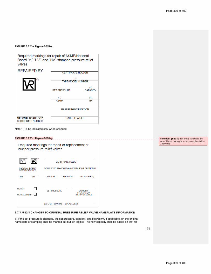
39
FIGURE 3.7.2-a Figure 5.7.5-e
Note 1. To be indicated only when changed FIGURE 3.7.2-b Figure 5.7.5-g
3.7.3 5.12.3 CHANGES TO ORIGINAL PRESSURE RELIEF VALVE NAMEPLATE INFORMATION a) If the set pressure is changed, the set pressure, capacity, and blowdown, if applicable, on the original nameplate or stamping shall be marked out but left legible. The new capacity shall be based on that for
Comment [BB33]: I’mprettysuretherearemore“Notes”thatapplytothisnameplateinPart3currently
Page 339 of 400
Page 339 of 400

40
which the valve was originally certified.
b) If the service fluid is changed, the capacity, including units, on the original nameplate or stamping shall be marked out but left legible. The new capacity shall be based on that for which the valve was originally certified, or if a conversion has been made, as described in NBIC Part 3, S7.2 3.2 on the capacity certification for the valve as converted.
c) If the Type/Model number is changed, the Type/Model number on the original nameplate shall be marked out but left legible.
d) If the blowdown is changed, the blowdown, if shown on the original nameplate or stamping, shall be marked out but left legible. The new blowdown may be based on the current ASME Code requirements.
e) Incorrect information on the original manufacturer’s nameplate shall be marked out but left legible. Corrected information shall be indicated on the repair nameplate and noted on the document as required by the quality system. 3.7.4 5.12.4 TEST ONLY NAMEPLATE a) Where a valve has been tested and adjusted to restore the set pressure shown on the unmodified original nameplate or stamping, or repair nameplate, as permitted by NBIC Part 3, S7.10.1 S3.1, but not otherwise repaired, a “Test Only” nameplate shall be applied that contains the following information: 1) Name of responsible organization;
2) Date of test;
3) Set Pressure; and
4) Identification, such as “Test Only.”
b) A “Test Only” nameplate is also recommended when periodic testing has been performed, even when no adjustments have been made, for the purpose of identifying the date the valve was tested.
c) The existing repair nameplates, if applicable, shall not be removed during such testing. 3.7.5 5.12.5 REPLACEMENT OF ILLEGIBLE OR MISSING NAMEPLATES a) Illegible Nameplates When the information on the original manufacturer’s or assembler’s nameplate or stamping is illegible, but traceability can be confirmed, the nameplate or stamping will shall be augmented by a nameplate furnished by the “VR” stamp holder stamped “Duplicate.” It shall contain all information that originally appeared on the nameplate or valve, as required by the applicable section of the ASME Code, except the “V,” “HV,” or “UV” symbol and the National Board mark. The repair organization’s nameplate, with the “VR” stamp and other required data specified in NBIC Part 3, 5.12.2 3.7.2, will make the repairer responsible to the owner and the Jurisdiction that the information on the duplicate nameplate is correct. b) Missing Nameplates When the original valve nameplate is missing, the repair organization is not authorized to perform repairs to the valve under the “VR” program, unless positive identification can be made to that specific valve and verification that the valve was originally stamped with an ASME “V” or UV” symbol or marked with an ASME “HV” symbol. Valves that can be positively identified will shall be equipped with a duplicate nameplate, as described in this section, in addition to the repairer’s “VR”-stamped nameplate. The repairer’s responsibilities for accurate data, as defined in NBIC Part 3, 5.12.5 3.7.5(a) (Illegible Nameplates), shall apply.
Page 340 of 400
Page 340 of 400
41
c) Marking of Original Code Stamp When a duplicate nameplate is affixed to a valve, as required by this section, it shall be marked “Sec. I,” “Sec. IV,” or “Sec. VIII,” as applicable, to indicate the original ASME Code stamping. 3.8 1.7 ACCREDITATION OF “VR” REPAIR ORGANIZATIONS 3.8.1 1.7.1 SCOPE These administrative rules and procedures are provided by the National Board for those who wish to obtain National Board Certificate of Authorization for use of the “VR” (Repair of Pressure Relief Valves) symbol stamp. It should be noted that the issuance of the “VR” stamp is not restricted to companies whose primary business is the repair of pressure relief valves, nor to manufacturers or assemblers that hold an ASME “V,”“HV,”“UV,” or “NV” Code Symbol Stamp. Owners and users of boilers and pressure vessels and other organizations that qualify in accordance with the National Board rules and regulations may also obtain the “VR” Certificate and stamp. 3.8.2 1.7.2 JURISDICTIONAL PARTICIPATION The National Board member jurisdiction in which the “VR” organization is located is encouraged to participate in the review and demonstration of the applicant’s quality system. The Jurisdiction may require participation in the review of the repair organization and the demonstration and acceptance of the repair organization’s quality system manual. 3.8.3 1.7.3 ISSUANCE AND RENEWAL OF THE “VR” CERTIFICATE OF AUTHORIZATION 3.8.3.1 1.7.3.1 GENERAL Authorization to use the stamp bearing the official National Board “VR” symbol as shown in NBIC Part 3 Section 5 Figure 3.7.2-a, will be granted by the National Board pursuant to the provisions of the following administrative rules and procedures. 3.8.3.2 1.7.3.2 ISSUANCE OF CERTIFICATE Repair organizations, manufacturers, assemblers, or users that make repairs to the ASME Code symbol stamped or marked pressure relief valvesand National Board capacity certified pressure relief valves may apply to the National Board for a Certificate of Authorization to use the “VR” symbol. 3.8.4 1.7.4 USE OF THE “VR” AUTHORIZATION 3.8.4.1 1.7.4.1 TECHNICAL REQUIREMENTS The administrative requirements of NBIC Part 3, 1.7 3.8 for use of the “VR” stamp shall be used in conjunction with the technical requirements for valve repair as described in sections 3.1 through 3.7 NBIC Part 3, Supplement 7. Those requirements shall be mandatory when a “VR” repair is performed. 3.8.4.2 1.7.4.2 STAMP USE Each “VR” symbol stamp shall be used only by the repair firm within the scope, limitations, and restrictions under which it was issued. 3.8.5 1.7.5 QUALITY SYSTEM 3.8.5.1 1.7.5.1 GENERAL Each applicant for a new or renewed “VR” Certificate of Authorization shall have and maintain a quality system which shall establish that all of these rules and administrative procedures and applicable ASME Code requirements, including material control, fabrication, machining, welding, examination, setting, testing, inspection, sealing, and stamping will be met.
Comment [BB34]: Maybechangethisword?Idon’tthinkmanypeopleknowwhattheword“pursuant”means
Page 341 of 400
Page 341 of 400
42
3.8.5.2 1.7.5.2 WRITTEN DESCRIPTION A written description, in the English language, of the system the applicant will use shall be available for review and shall contain, as a minimum, the features set forth in NBIC Part 3, 1.7.5.4 3.8.5.4. This description may be brief or voluminous, depending upon the projected scope of work, and shall be treated confidentially. In general, the quality system shall describe and explain what documents and procedures the repair firm will use to validate a valve repair. 3.8.5.3 1.7.5.3 MAINTENANCE OF CONTROLLED COPY Each applicant to whom a “VR” Certificate of Authorization is issued shall maintain thereafter a controlled copy of the accepted quality system manual with the National Board. Except for changes that do not affect the quality system, revisions to the quality system manual shall not be implemented until such revisions are accepted by the National Board. 3.8.5.4 1.7.5.4 OUTLINE OF REQUIREMENTS FOR A QUALITY SYSTEM The following establishes the minimum requirements of the written description of the quality system. It is required that each valve repair organization develop its own quality system that meets the requirements of its organization. For this reason it is not possible to develop one quality system that could apply to more than one organization. The written description shall include, as a minimum, the following features: a) Title Page The title page shall include the name and address of the company to which the National Board Certificate of Authorization is to be issued.
b) Revision Log A revision log is required to shall be included to ensure revision control of the quality system manual. The log should contain sufficient space for date, description and section of revision, company approval, and National Board acceptance.
c) Contents Page The contents page should shall list and reference, by paragraph and page number, the subjects and exhibits contained therein.
d) Statement of Authority and Responsibility A statement of authority and responsibility shall be dated and signed by an officer of the company. It shall include:
1) A statement that the “VR” stamp shall be applied only to pressure relief valves that meet both of the following conditions:
a. Are stamped with an ASME “V”, “UV”, or “NV” Code symbol or marked with an ASME “HV” symbol and have been capacity certified by the National Board; and
b. Have been disassembled, inspected, and repaired by the Certificate Holder such that the valves’ condition and performance are equivalent to the standards for new valves.
2) The title of the individual responsible to ensure that the quality system is followed and who has authority and freedom to effect the responsibility;
3) A statement that if there is a disagreement in the implementation of the written quality system, the matter is to be referred to a higher authority in the company for resolution; and
Comment [BB35]: NBIClanguage
Comment [BB36]: Thisisarequirement,so“shall”shouldbeused
Page 342 of 400
Page 342 of 400
43
4) The title of the individual authorized to approve revisions to the written quality system and the method by which such revisions are to be submitted to the National Board for acceptance before implementation.
e) Organization Chart A chart showing the relationship between management, purchasing, repairing, inspection, and quality control personnel is requiredshall be included and shall reflect the actual organization in place.
f) Scope of Work 1) The scope of work section shall indicate the scope and type of valve repairs, including conversions the organization is capable of and intends to perform. The location of repairs (shop, shop and field, or field only), ASME Code Section(s) to which the repairs apply, the test medium (air, gas, liquid, or steam, or combinations thereof), and special processes (machining, welding, postweld heat treatment, or nondestructive examination, or combinations thereof) shall be specifically addressed.
2) The types and sizes of valves to be repaired, pressure ranges and other limitations, such as engineering and test facilities, should also be addressed.
g) Drawings and Specification Control
The drawings and specification control system shall provide procedures assuring that the latest applicable drawings, specifications, and instructions required are used for valve repair, including conversions, inspection, and testing.
h) Material and Part Control The material and part control section shall describe purchasing, receiving, storage, and issuing of parts.
1) State the titleThe title of the individual responsible for the purchasing of all material shall be stated.
2) State the titleThe title of the individual responsible for certification and other records as required shall be stated.
3) All incoming material and parts shall be checked for conformance with the purchase order and, where applicable, the material specifications or drawings. Indicate how material or part is identified and how identity is maintained by the quality system.
i) Repair and Inspection Program The repair and inspection program section shall include reference to a document (such as a report, traveler, or checklist) that outlines the specific repair and inspection procedures used in the repair of pressure relief valves. Repair procedures shall require verification that the critical parts meet the valve manufacturer’s specification. Supplement S-7.14 S4 outlines recommended procedures covering some specific items. Provisions shall be made to retain this document for a period of at least five years.
1) Each valve or group of valves shall be accompanied by the document referred to above for processing through the plant. Each valve shall have a unique identifier (i.e., repair serial number, shop order number, etc.) appearing on the repair documentation and repair nameplate such that traceability is established.
2) The document referred to above shall describe the original nameplate information, including the ASME Code symbol stamping and the repair nameplate information, if applicable. In addition, it shall include material checks, replacement parts, conversion parts (or both), reference to items such as the welding procedure specifications (WPS), fitup, NDE technique, heat treatment, and pressure test methods to be used. Application of the “VR” stamp to the repair nameplate shall be recorded in this document. Specific conversions performed with the new Type/Model number shall be recorded on the document. There shall be a space for “signoffs” at each operation to verify that each step has been properly performed.
3) The system shall include a method of controlling the repair or replacement of critical valve parts. The method of
Comment [BB37]: NBIClanguage
Comment [BB38]: NBIClanguage
Page 343 of 400
Page 343 of 400
44
identifying each spring shall be indicated.
4) The system shall also describe the controls used to ensure that any personnel engaged in the repair of pressure relief valves are trained and qualified in accordance with NBIC Part 3 Supplement 7, this section.
j) Welding, NDE, and Heat Treatment (when applicable) The quality system manual shall indicate the title of the person(s) responsible for and describe the system used in the selection, development, approval, and qualification of welding procedure specifications, and the qualification of welders and welding operators in accordance with the provisions of NBIC Part 3, S7.12 & S7.13 3.4.
1) The quality system manual may include controls for the “VR” Certificate Holder to have the pressure relief valve part repaired by a National Board “R” Certificate Holder, per NBIC Part 3, S7.3 3.4.7.
2) The completed Form R-1 shall be noted on and attached to the “VR” Certificate Holder’s document required in NBIC Part 3, 1.7.7.5i) 3.8.5.4 i). Similarly, NDE and heat treatment techniques must be covered in the quality system manual. When outside services are used for NDE and heat treatment, the quality system manual shall describe the system whereby the use of such services meet the requirements of the applicable section of the ASME Code.
k) Valve Testing, Setting, and Sealing The system shall include provisions that each valve shall be tested, set, and all external adjustments sealed according to the requirements of the applicable ASME Code Section and the National Board. The seal shall identify the “VR” Certificate Holder making the repair. Abbreviations or initials shall be permitted, provided such identification is acceptable to the National Board.
l) Valve Repair Nameplates An effective valve stamping system shall be established to ensure proper stamping of each valve as required by NBIC Part 3, 5.12.2 3.7.2. The manual shall include a description of the nameplate or a drawing.
m) Calibration 1) The manual shall describe a system for the calibration of examination, measuring, and test equipment used in the performance of repairs. Documentation of these calibrations shall include the standard used and the results.
2) All calibration standards shall be calibrated against certified equipment having known valid relationships to nationally recognized standards.
n) Manual Control The quality system shall include:
1) Measures to control the issuance of and revisions to the quality system manual;
2) Provisions for a review of the system in order to maintain the manual current with these rules and the applicable sections of the ASME Code;
3) The title(s) of the individual(s) responsible for control, revisions, and review of the manual;
4) Provision of a controlled copy of the written quality system manual to be submitted to the National Board; and
5) Revisions shall be submitted for acceptance by the National Board prior to being implemented.
o) Nonconformities
Page 344 of 400
Page 344 of 400

45
The system shall establish measures for the identification, documentation, evaluation, segregation, and disposition of nonconformities. A nonconformity is a condition of any material, item, product, or process in which one or more characteristics do not conform to the established requirements. These may include, but are not limited to, data discrepancies, procedural and/or documentation deficiencies, or material defects. Also, the title(s) of the individual(s) involved in this process shall be included.
p) Exhibits Forms used in the quality system shall be included in the manual with a written description. Forms exhibited should be marked SAMPLE and completed in a manner typical of actual valve repair procedures.
q) Testing Equipment
The system shall include a means to control the development, addition, or modification of testing equipment to ensure the requirements of NBIC Part 3, 4.5.1(b) 3.6.1 b) and 3.6.3 c) are met.
(See NBIC Part 3, Supplement 8 Supplement 5 for a guide on the sizing of pressure vessels used as part of pressure relief valve test equipment)r) Field Repairs If field repairs are included in the scope of work, the system shall address any differences or additions to the quality system required to properly control this activity, including the following:
1) Provisions for annual audits of field activities shall be included;
2) Provisions for receipt and inspection of replacement parts, including parts received from the owner-user, shall be addressed;
3) If owner-user personnel will assist with repairs, provisions for the use of owner user personnel shall be included; and
4) Provisions for use of owner-user measurement and test equipment, if applicable, shall be addressed. 3.8.6 S7.7 FIELD REPAIR Repair organizations may obtain a “VR” Certificate of Authorization for field repair, either as an extension to their in-shop/plant scope, or as a field-only scope, provided that: a) Qualified technicians in the employ of the Certificate Holder perform such repairs;
b) An acceptable quality system covering field repairs, including field audits, is maintained;
c) Functions affecting the quality of the repaired valves are supervised from the address of record where the “VR” certification is issued. 3.8.6.1 S7.8 AUDIT REQUIREMENTS Upon issuance of a Certificate of Authorization, provided field repairs are performed, annual audits of the work carried out in the field shall be performed to ensure that the requirements of the Certificate Holder’s quality system are met. The audit shall include, but not be limited to, performance testing, in accordance with NBIC Part 3, 4.5 3.6, of valve(s) that were repaired in the field. The audits shall be documented. 3.8.6.2 S7.9 USE OF OWNER-USER PERSONNEL For the repair of pressure relief valves at an owner-user’s facility for the owner-user’s own use, the “VR” Certificate Holder may utilize owner-user personnel to assist Certificate Holder technician(s) in the performance of repairs provided: a) The use of such personnel is addressed in the “VR” Certificate Holder’s quality system;
Page 345 of 400
Page 345 of 400

46
b) The owner-user personnel are trained and qualified in accordance with NBIC Part 3, S7.10 Supplement 3
c) Owner-user personnel work under direct supervision and control of the “VR” Certificate Holder’s technician(s) during any stage of the repair when they are utilized;
d) The “VR” Certificate Holder shall have the authority to assign and remove owner-user personnel at its own discretion; and
e) The names of the owner-user personnel utilized are recorded on the document as required for a quality system. 3.9 S7.11 TRAINING AND QUALIFICATION OF PERSONNEL S7.11.1 GENERAL 3.9.1 S7.11.2 CONTENTS OF TRAINING PROGRAM The repair organization shall establish a documented in-house training program. This program shall establish training objectives and provide a method of evaluating training effectiveness. As a minimum, training objectives for knowledge level shall include: a) Applicable ASME Code and NBIC requirements;
b) Responsibilities within the organization’s quality system; and
c) Knowledge of the technical aspects and mechanical skills for the applicable position held. 3.9.2 S7.11.3 QUALIFICATION OF PERSONNEL Each repair organization shall establish minimum qualification requirements for those positions within the organization as they directly relate to pressure relief valve repair. Each repair organization shall document the evaluation and acceptance of an individual’s qualification for the applicable position. 3.9.3 S7.11.4 ANNUAL REVIEW OF QUALIFICATION The repair organization shall annually review the qualifications of repair personnel to verify proficiency as well as compliance with the Certificate Holder’s quality system. This review shall include training records, documented evidence of work performed, and when necessary, monitoring job performance. The review shall be documented.
Page 346 of 400
Page 346 of 400
47
SUPPLEMENTS
SUPPLEMENT 1 PRESSURE RELIEF SAFETY VALVES ON THE LOW PRESSURE SIDE OF STEAM PRESSURE-REDUCING VALVES (was Part 1 Supplement 2) S1.1 S2.1 SCOPE a) The subject of protection of vessels in steam service connected to the low-pressure side of a steam-pressure-reducing valve is of considerable importance to proper operation of auxiliary equipment such as pressure cookers, hot-water heating systems, etc., operating at pressures below that which the primary boiler generating unit is operating.
b) To automatically reduce the primary boiler pressure for such processing equipment, pressure-reducing valves are used. The manufacturers of such equipment have data available listing the volume of flow through reducing valves manufactured by them, but such data are not compiled in a form that the results can be deduced readily. To protect the equipment operating on the low pressure side of a pressure-reducing valve, safety pressure relief valves of a relieving capacity sufficient to prevent an unsafe pressure rise in case of failure of the pressure-reducing valve, should be installed.
c) The pressure-reducing valve is a throttling device, the design of which is based on certain diaphragm pressures opposed by spring pressure which, in turn, controls the opening through the valve. If the spring, the diaphragm, or any part of the pressure- reducing valve fails, steam will flow directly through the valve and the low pressure equipment will be subjected to the boiler pressure. To protect the equipment operating on the low pressure side of the pressure-reducing valve, safety pressure relief valve(s) should be installed on the low pressure side of the pressure-reducing valve, which will provide a relieving capacity sufficient to prevent the pressure from rising above the system design pressure.
d) In most cases pressure-reducing valves used for the reduction of steam pressures have the same pipe size on the inlet and outlet. In case of failure of a pressure-reducing valve, the safety pressure relief valve on the low-pressure side must have a capacity to take care of the volume of steam determined by the high pressure side and the area of the pipe. S1.2 S2.2 SAFETY PRESSURE RELIEF VALVE CAPACITY a) The capacity of the safety pressure relief valve(s) on the low-pressure side of the pressure-reducing valve should be based on the capacity of the pressure-reducing valve when wide open or under maximum flow conditions or the flow capacity through the bypass valve. b) By using the formula in NBIC Part1, S2.3 S1.3 below, Inspectors may calculate the required relieving capacities of the safety pressure relief valve(s) installed on the low-pressure side of the pressure reducing valve.
c) Usually a pressure-reducing valve has a bypass arrangement so that in case of failure of the pressure-reducing valve the boiler pressure may be short circuited into the low-pressure line without passing through the pressure-reducing valve. When determining the required relieving capacity of safety pressure relief valves for the low-pressure side of the pressure-reducing valve, the steam flow through the bypass must be taken into consideration. S1.3 S2.3 CALCULATION OF SAFETY VALVE RELIEVING CAPACITY a) When a pressure-reducing valve is installed, there are two possibilities of introducing boiler pressure into the low-pressure system: 1) the failure of the pressure-reducing valve so that it remains wide open; and
Comment [BB39]: Isthisjustarecommendation,orarequirement?
Page 347 of 400
Page 347 of 400

48
2) the possibility of the bypass valve being open.
b) It is necessary therefore, to determine the flow under both circumstances in paragraph a) above and check that the size of the safety valve under either condition will be adequate. The following formula should be used:
1) steam flow, W in lbs/hr (kg/hr) through the pressure-reducing valve W = AKC where, A = internal area in in.2 (mm2) of the inlet pipe size of the pressure reducing valve (see NBIC Part 1, S2.5 S1.5) K = flow coefficient for the pressure reducing valve (see NBIC Part 1, S2.4 S1.4) C = flow of saturated steam through a 1 in.2 (1 mm2) pipe at various pressure differentials from NBIC Part 1 Tables S2.3-a, S2.3-b, or S2.3-c Tables S1.3-a, S1.3-b, or S1.3-c. (for U.S. Customary units) or NBIC Part 1 Tables S2.3M-a, S2.3M-b, or S2.3M-c Tables S1.3M-a, S1.3M-b, or S1.3M-c ( for metric units). 2) steam flow, W in lbs/hr (kg/hr) through the by-pass valve W = A1K1C1 where, A1 = internal area in in.2 (mm2) of the pipe size of the bypass around the pressure-reducing valve K1 = flow coefficient for the bypass valves (see NBIC Part 1, S2.4 S1.4) C1 = flow of saturated steam through a 1 in.2 (1 mm2) pipe at various pressure differentials from NBIC Part 1 Tables S2.3-a, S2.3-b, or S2.3-c Tables S1.3-a, S1.3-b, or S1.3-c. (for U.S. Customary units) or NBIC Part 1 Tables S2.3M-a, S2.3M-b, or S2.3M-c Tables S1.3M-a, S1.3M-b, or S1.3M-c ( for metric units). Table S1.3-a S2.3-a Capacity of saturated steam, in lbs/hr, per in.2 of Pipe Area outlet pres., Pressure-reducing valve inlet pressure, psi psi 1500 1450 1400 1350 1300 1250 1200 1150 1100 1050 1000 950 900
1000 76560 72970 69170 64950 60540 55570 49930 43930 35230 25500 . . . . . . . . . . . . . . .
950 77430 74180 70760 67000 63100 58770 53920 48610 42380 34890 24910 . . . . . . . . . .
900 77750 74810 71720 68340 64870 61040 56820 52260 47050 41050 33490 23960 . . . . .
850 77830 74950 72160 69130 66020 62610 58900 54930 50480 45470 39660 29080 23190
800 . . . . . 75070 72330 69490 66700 63680 60390 56910 53060 48800 43980 38340 31610
750 . . . . . . . . . . . . . . . 69610 66880 64270 61260 58200 54840 51170 47080 42420 37110
700 . . . . . . . . . . . . . . . . . . . . 66900 64270 61520 58820 55870 52670 49170 45230 40860
650 . . . . . . . . . . . . . . . . . . . . . . . . . . . . . . 61550 58860 56260 53480 50440 47070 43400
600 . . . . . . . . . . . . . . . . . . . . . . . . . . . . . . . . . . . 58980 56270 53660 51020 48470 45010
550 . . . . . . . . . . . . . . . . . . . . . . . . . . . . . . . . . . . . . . . . . . . . . 53810 51040 48470 45800
500 . . . . . . . . . . . . . . . . . . . . . . . . . . . . . . . . . . . . . . . . . . . . . . . . . . . . . . . . . . . . 45850
450 . . . . . . . . . . . . . . . . . . . . . . . . . . . . . . . . . . . . . . . . . . . . . . . . . . . . . . . . . . . . 45870
400 . . . . . . . . . . . . . . . . . . . . . . . . . . . . . . . . . . . . . . . . . . . . . . . . . . . . . . . . . . . . . . . . .
350 . . . . . . . . . . . . . . . . . . . . . . . . . . . . . . . . . . . . . . . . . . . . . . . . . . . . . . . . . . . . . . . . .
300 . . . . . . . . . . . . . . . . . . . . . . . . . . . . . . . . . . . . . . . . . . . . . . . . . . . . . . . . . . . . . . . . .
250 . . . . . . . . . . . . . . . . . . . . . . . . . . . . . . . . . . . . . . . . . . . . . . . . . . . . . . . . . . . . . . . . .
200 . . . . . . . . . . . . . . . . . . . . . . . . . . . . . . . . . . . . . . . . . . . . . . . . . . . . . . . . . . . . . . . . .
175 . . . . . . . . . . . . . . . . . . . . . . . . . . . . . . . . . . . . . . . . . . . . . . . . . . . . . . . . . . . . . . . . .
150 . . . . . . . . . . . . . . . . . . . . . . . . . . . . . . . . . . . . . . . . . . . . . . . . . . . . . . . . . . . . . . . . .
125 . . . . . . . . . . . . . . . . . . . . . . . . . . . . . . . . . . . . . . . . . . . . . . . . . . . . . . . . . . . . . . . . .
110 . . . . . . . . . . . . . . . . . . . . . . . . . . . . . . . . . . . . . . . . . . . . . . . . . . . . . . . . . . . . . . . . .
100 . . . . . . . . . . . . . . . . . . . . . . . . . . . . . . . . . . . . . . . . . . . . . . . . . . . . . . . . . . . . . . . . .
85 . . . . . . . . . . . . . . . . . . . . . . . . . . . . . . . . . . . . . . . . . . . . . . . . . . . . . . . . . . . . . . . . .
75 . . . . . . . . . . . . . . . . . . . . . . . . . . . . . . . . . . . . . . . . . . . . . . . . . . . . . . . . . . . . . . . . .
60 . . . . . . . . . . . . . . . . . . . . . . . . . . . . . . . . . . . . . . . . . . . . . . . . . . . . . . . . . . . . . . . . .
50 . . . . . . . . . . . . . . . . . . . . . . . . . . . . . . . . . . . . . . . . . . . . . . . . . . . . . . . . . . . . . . . . .
40 . . . . . . . . . . . . . . . . . . . . . . . . . . . . . . . . . . . . . . . . . . . . . . . . . . . . . . . . . . . . . . . . .
30 . . . . . . . . . . . . . . . . . . . . . . . . . . . . . . . . . . . . . . . . . . . . . . . . . . . . . . . . . . . . . . . . .
25 . . . . . . . . . . . . . . . . . . . . . . . . . . . . . . . . . . . . . . . . . . . . . . . . . . . . . . . . . . . . . . . . .
15 . . . . . . . . . . . . . . . . . . . . . . . . . . . . . . . . . . . . . . . . . . . . . . . . . . . . . . . . . . . . . . . . .
10 . . . . . . . . . . . . . . . . . . . . . . . . . . . . . . . . . . . . . . . . . . . . . . . . . . . . . . . . . . . . . . . . .
5 . . . . . . . . . . . . . . . . . . . . . . . . . . . . . . . . . . . . . . . . . . . . . . . . . . . . . . . . . . . . . . . . .
Where capacities are not shown for inlet and outlet conditions, use the highest capacity shown under the applicable inlet pressure column.
Table S1.3M-a S2.3M-a
Comment [BB40]: Isthissupposedtobeaconversion?Because1sq.mmdoesnotequal1sq.in.
Comment [BB41]: Thisdoesn’tmakesense“Winlbs/hr”
Comment [BB42]: Samecommentasabove
Page 348 of 400
Page 348 of 400
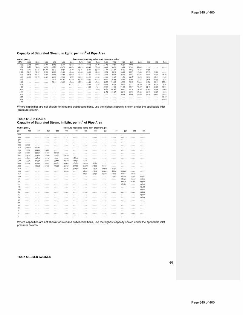
49
Capacity of Saturated Steam, in kg/hr, per mm2 of Pipe Area outlet pres., Pressure-reducing valve inlet pressure, mPa mPa 10.25 10.00 9.75 9.50 9.25 9.00 8.75 8.50 8.25 8.00 7.75 7.50 7.25 7.00 6.75 6.50 6.25
6.75 53.44 51.68 49.82 47.85 45.77 43.63 41.28 38.73 36.01 33.09 29.47 25.37 20.89 . . . . . . . . . . . . . . . . . . . .
6.50 53.87 52.23 50.52 48.69 46.79 44.83 42.69 40.40 37.95 35.30 32.33 29.02 25.31 20.46 . . . . . . . . . . . . . . .
6.25 54.07 52.55 50.96 49.27 47.51 45.71 43.75 41.67 39.46 37.08 34.46 31.59 28.43 24.45 19.36 . . . . . . . . . .
6.00 54.15 52.67 51.19 49.62 47.99 46.33 44.53 42.63 40.62 38.74 36.12 33.59 30.83 27.53 23.13 17.64 . . . . .
5.75 54.19 52.74 51.32 49.85 48.33 45.80 45.14 43.40 41.56 39.62 37.51 35.25 32.82 30.04 26.20 21.90 18.76
5.50 54.20 52.78 51.40 49.97 48.53 47.11 45.60 44.00 42.32 40.55 38.56 36.63 34.48 32.05 29.37 26.41 23.01
5.25 . . . . . . . . . . . . . . . 50.00 48.60 47.20 45.82 44.35 42.78 41.17 39.44 37.62 35.68 33.52 31.16 28.59 25.72
5.00 . . . . . . . . . . . . . . . 50.01 48.62 47.23 45.89 44.49 43.02 41.55 39.98 38.33 36.57 34.64 32.56 30.01 27.84
4.75 . . . . . . . . . . . . . . . . . . . . . . . . . 47.24 . . . . . 44.52 43.13 41.75 40.31 38.81 37.22 35.50 33.64 31.66 29.51
4.50 . . . . . . . . . . . . . . . . . . . . . . . . . . . . . . . . . . . 44.53 43.14 41.77 40.43 39.08 37.63 36.07 34.41 32.65 30.76
4.25 . . . . . . . . . . . . . . . . . . . . . . . . . . . . . . . . . . . . . . . . 43.15 41.82 40.46 39.10 37.74 36.33 34.90 33.39 31.60
4.00 . . . . . . . . . . . . . . . . . . . . . . . . . . . . . . . . . . . . . . . . . . . . . 41.84 40.48 39.12 37.82 36.45 35.12 33.76 32.15
3.75 . . . . . . . . . . . . . . . . . . . . . . . . . . . . . . . . . . . . . . . . . . . . . . . . . . . . . . . 39.14 37.88 36.48 35.13 33.81 32.45
3.50 . . . . . . . . . . . . . . . . . . . . . . . . . . . . . . . . . . . . . . . . . . . . . . . . . . . . . . . . . . . . . . . . . . . . . . . . . . . . . . . . 32.47
3.25 . . . . . . . . . . . . . . . . . . . . . . . . . . . . . . . . . . . . . . . . . . . . . . . . . . . . . . . . . . . . . . . . . . . . . . . . . . . . . . . . 32.48
3.00 . . . . . . . . . . . . . . . . . . . . . . . . . . . . . . . . . . . . . . . . . . . . . . . . . . . . . . . . . . . . . . . . . . . . . . . . . . . . . . . . . . . . .
Where capacities are not shown for inlet and outlet conditions, use the highest capacity shown under the applicable inlet pressure column. Table S1.3-b S2.3-b Capacity of Saturated Steam, in lb/hr, per in.2 of Pipe Area Outlet pres., Pressure-reducing valve inlet pressure, psi psi 850 800 750 700 650 600 550 500 450 400 350 300 250
Where capacities are not shown for inlet and outlet conditions, use the highest capacity shown under the applicable inlet pressure column. Table S1.3M-b S2.3M-b
1000 . . . . . . . . . . . . . . . . . . . . . . . . . . . . . . . . . . . . . . . . . . . . . . . . . . . . . . . . . . . . . . . . .
950 . . . . . . . . . . . . . . . . . . . . . . . . . . . . . . . . . . . . . . . . . . . . . . . . . . . . . . . . . . . . . . . . .
900 . . . . . . . . . . . . . . . . . . . . . . . . . . . . . . . . . . . . . . . . . . . . . . . . . . . . . . . . . . . . . . . . .
850 . . . . . . . . . . . . . . . . . . . . . . . . . . . . . . . . . . . . . . . . . . . . . . . . . . . . . . . . . . . . . . . . .
800 22550 . . . . . . . . . . . . . . . . . . . . . . . . . . . . . . . . . . . . . . . . . . . . . . . . . . . . . . . . . . . .
750 30600 21800 . . . . . . . . . . . . . . . . . . . . . . . . . . . . . . . . . . . . . . . . . . . . . . . . . . . . . . .
700 35730 29420 21020 . . . . . . . . . . . . . . . . . . . . . . . . . . . . . . . . . . . . . . . . . . . . . . . . . .
650 39200 34250 28260 20190 . . . . . . . . . . . . . . . . . . . . . . . . . . . . . . . . . . . . . . . . . . . . .
600 41500 37470 32800 27090 19480 . . . . . . . . . . . . . . . . . . . . . . . . . . . . . . . . . . . . . . . .
550 42840 39850 35730 31310 25940 18620 . . . . . . . . . . . . . . . . . . . . . . . . . . . . . . . . . . .
500 43330 40530 37610 33880 29760 24630 17720 . . . . . . . . . . . . . . . . . . . . . . . . . . . . . .
450 43330 40730 38150 35260 31980 28080 23290 16680 . . . . . . . . . . . . . . . . . . . . . . . . .
400 . . . . . 40760 38220 35680 33050 29980 26380 21870 15760 . . . . . . . . . . . . . . . . . . . .
350 . . . . . . . . . . . . . . . . . . . . 33120 30690 27910 24570 20460 14790 . . . . . . . . . . . . . . .
300 . . . . . . . . . . . . . . . . . . . . 33240 . . . . . 28140 25610 22620 18860 13630 . . . . . . . . . .
250 . . . . . . . . . . . . . . . . . . . . . . . . . . . . . . 28150 25650 23200 21000 17100 10800 . . . . .
200 . . . . . . . . . . . . . . . . . . . . . . . . . . . . . . . . . . . . . . . . . . . . . 21350 18250 15350 10900
175 . . . . . . . . . . . . . . . . . . . . . . . . . . . . . . . . . . . . . . . . . . . . . . . . . . 18250 16000 12600
150 . . . . . . . . . . . . . . . . . . . . . . . . . . . . . . . . . . . . . . . . . . . . . . . . . . 18250 16200 13400
125 . . . . . . . . . . . . . . . . . . . . . . . . . . . . . . . . . . . . . . . . . . . . . . . . . . 18780 . . . . . 13600
110 . . . . . . . . . . . . . . . . . . . . . . . . . . . . . . . . . . . . . . . . . . . . . . . . . . . . . . . . . . . . 13600
100 . . . . . . . . . . . . . . . . . . . . . . . . . . . . . . . . . . . . . . . . . . . . . . . . . . . . . . . . . . . . 13600
85 . . . . . . . . . . . . . . . . . . . . . . . . . . . . . . . . . . . . . . . . . . . . . . . . . . . . . . . . . . . . 13600
75 . . . . . . . . . . . . . . . . . . . . . . . . . . . . . . . . . . . . . . . . . . . . . . . . . . . . . . . . . . . . 13600
60 . . . . . . . . . . . . . . . . . . . . . . . . . . . . . . . . . . . . . . . . . . . . . . . . . . . . . . . . . . . . 13630
50 . . . . . . . . . . . . . . . . . . . . . . . . . . . . . . . . . . . . . . . . . . . . . . . . . . . . . . . . . . . . . . . . .
40 . . . . . . . . . . . . . . . . . . . . . . . . . . . . . . . . . . . . . . . . . . . . . . . . . . . . . . . . . . . . . . . . .
30 . . . . . . . . . . . . . . . . . . . . . . . . . . . . . . . . . . . . . . . . . . . . . . . . . . . . . . . . . . . . . . . . .
25 . . . . . . . . . . . . . . . . . . . . . . . . . . . . . . . . . . . . . . . . . . . . . . . . . . . . . . . . . . . . . . . . .
15 . . . . . . . . . . . . . . . . . . . . . . . . . . . . . . . . . . . . . . . . . . . . . . . . . . . . . . . . . . . . . . . . .
10 . . . . . . . . . . . . . . . . . . . . . . . . . . . . . . . . . . . . . . . . . . . . . . . . . . . . . . . . . . . . . . . . .
5 . . . . . . . . . . . . . . . . . . . . . . . . . . . . . . . . . . . . . . . . . . . . . . . . . . . . . . . . . . . . . . . . .
Page 349 of 400
Page 349 of 400

50
Capacity of saturated steam, in kg/hr, per mm2 of Pipe Area
outlet pres., Pressure-reducing valve inlet pressure, mPa mPa 6.00 5.75 5.50 5.25 5.00 4.75 4.50 4.25 4.00 3.75 3.50 3.25 3.00 2.75 2.50 2.25 2.00 1.75
5.75 . . . . . . . . . . . . . . . . . . . . . . . . . . . . . . . . . . . . . . . . . . . . . . . . . . . . . . . . . . . . . . . . . . . . . . . . . . . . . . . . . . . . . . . . . . 5.50 18.66 . . . . . . . . . . . . . . . . . . . . . . . . . . . . . . . . . . . . . . . . . . . . . . . . . . . . . . . . . . . . . . . . . . . . . . . . . . . . . . . . . . . . . 5.25 22.24 17.52 . . . . . . . . . . . . . . . . . . . . . . . . . . . . . . . . . . . . . . . . . . . . . . . . . . . . . . . . . . . . . . . . . . . . . . . . . . . . . . . . 5.00 24.96 21.60 17.50 . . . . . . . . . . . . . . . . . . . . . . . . . . . . . . . . . . . . . . . . . . . . . . . . . . . . . . . . . . . . . . . . . . . . . . . . . . . 4.75 27.06 24.31 21.18 17.17 . . . . . . . . . . . . . . . . . . . . . . . . . . . . . . . . . . . . . . . . . . . . . . . . . . . . . . . . . . . . . . . . . . . . . . 4.50 28.64 26.30 23.70 20.58 16.54 . . . . . . . . . . . . . . . . . . . . . . . . . . . . . . . . . . . . . . . . . . . . . . . . . . . . . . . . . . . . . . . . . 4.25 29.71 27.67 25.44 22.83 19.75 15.63 . . . . . . . . . . . . . . . . . . . . . . . . . . . . . . . . . . . . . . . . . . . . . . . . . . . . . . . . . . . . 4.00 30.49 28.74 26.86 24.59 22.06 19.18 15.75 . . . . . . . . . . . . . . . . . . . . . . . . . . . . . . . . . . . . . . . . . . . . . . . . . . . . . . . 3.75 30.99 29.49 27.95 25.92 23.77 21.42 18.76 15.23 . . . . . . . . . . . . . . . . . . . . . . . . . . . . . . . . . . . . . . . . . . . . . . . . . . 3.50 31.15 29.77 28.32 26.74 24.90 22.87 20.68 17.93 14.24 . . . . . . . . . . . . . . . . . . . . . . . . . . . . . . . . . . . . . . . . . . . . . 3.25 31.18 29.86 28.49 27.10 25.53 23.81 21.95 19.73 17.12 13.72 . . . . . . . . . . . . . . . . . . . . . . . . . . . . . . . . . . . . . . . . 3.00 31.19 29.88 28.56 27.25 25.86 24.40 22.82 20.98 18.90 16.51 13.46 . . . . . . . . . . . . . . . . . . . . . . . . . . . . . . . . . . . 2.75 . . . . . . . . . . 28.58 27.28 25.98 24.68 23.34 21.79 20.09 18.19 15.90 12.98 . . . . . . . . . . . . . . . . . . . . . . . . . . . . . . 2.50 . . . . . . . . . . . . . . . . . . . . . . . . . . . . . . 23.37 22.05 20.62 19.04 17.19 14.94 11.83 . . . . . . . . . . . . . . . . . . . . . . . . . 2.25 . . . . . . . . . . . . . . . . . . . . . . . . . . . . . . 23.42 22.15 20.83 19.45 17.94 16.18 14.11 11.59 . . . . . . . . . . . . . . . . . . . . 2.00 . . . . . . . . . . . . . . . . . . . . . . . . . . . . . . 23.46 22.17 20.87 19.57 18.28 16.85 15.26 13.48 10.95 . . . . . . . . . . . . . . . 1.75 . . . . . . . . . . . . . . . . . . . . . . . . . . . . . . . . . . . . . . . . . . . . . 19.58 18.30 17.03 15.79 14.59 12.54 9.55 . . . . . . . . . . 1.50 . . . . . . . . . . . . . . . . . . . . . . . . . . . . . . . . . . . . . . . . . . . . . . . . . . . . . . . 17.05 15.90 14.84 12.12 10.46 8.75 . . . . . 1.25 . . . . . . . . . . . . . . . . . . . . . . . . . . . . . . . . . . . . . . . . . . . . . . . . . . . . . . . . . . . . 15.92 14.95 12.98 11.75 10.62 8.75 1.00 . . . . . . . . . . . . . . . . . . . . . . . . . . . . . . . . . . . . . . . . . . . . . . . . . . . . . . . . . . . . . . . . . 14.96 13.44 12.19 11.00 9.60 0.90 . . . . . . . . . . . . . . . . . . . . . . . . . . . . . . . . . . . . . . . . . . . . . . . . . . . . . . . . . . . . . . . . . 14.97 13.60 12.30 11.02 9.67 0.80 . . . . . . . . . . . . . . . . . . . . . . . . . . . . . . . . . . . . . . . . . . . . . . . . . . . . . . . . . . . . . . . . . . . . . . 13.66 12.35 11.03 9.70 0.70 . . . . . . . . . . . . . . . . . . . . . . . . . . . . . . . . . . . . . . . . . . . . . . . . . . . . . . . . . . . . . . . . . . . . . . . . . . . . . . . . . . . . . 9.70 0.60 . . . . . . . . . . . . . . . . . . . . . . . . . . . . . . . . . . . . . . . . . . . . . . . . . . . . . . . . . . . . . . . . . . . . . . . . . . . . . . . . . . . . . 9.70 0.50 . . . . . . . . . . . . . . . . . . . . . . . . . . . . . . . . . . . . . . . . . . . . . . . . . . . . . . . . . . . . . . . . . . . . . . . . . . . . . . . . . . . . . 9.70 0.40 . . . . . . . . . . . . . . . . . . . . . . . . . . . . . . . . . . . . . . . . . . . . . . . . . . . . . . . . . . . . . . . . . . . . . . . . . . . . . . . . . . . . . 9.72 0.30 . . . . . . . . . . . . . . . . . . . . . . . . . . . . . . . . . . . . . . . . . . . . . . . . . . . . . . . . . . . . . . . . . . . . . . . . . . . . . . . . . . . . . . . . . .
Where capacities are not shown for inlet and outlet conditions, use the highest capacity shown under the applicable inlet pressure column. Table S1.3-c S2.3-c Capacity of Saturated Steam, in lb/hr, per in.2 of Pipe Area Outlet pres., Pressure-reducing valve inlet pressure, psi Psi 200 175 150 125 100 85 75 60 50 40 30 25
1000 . . . . . . . . . . . . . . . . . . . . . . . . . . . . . . . . . . . . . . . . . . . . . . . . . . . . . . . . . . . .950 . . . . . . . . . . . . . . . . . . . . . . . . . . . . . . . . . . . . . . . . . . . . . . . . . . . . . . . . . . . .900 . . . . . . . . . . . . . . . . . . . . . . . . . . . . . . . . . . . . . . . . . . . . . . . . . . . . . . . . . . . .850 . . . . . . . . . . . . . . . . . . . . . . . . . . . . . . . . . . . . . . . . . . . . . . . . . . . . . . . . . . . .800 . . . . . . . . . . . . . . . . . . . . . . . . . . . . . . . . . . . . . . . . . . . . . . . . . . . . . . . . . . . .750 . . . . . . . . . . . . . . . . . . . . . . . . . . . . . . . . . . . . . . . . . . . . . . . . . . . . . . . . . . . .700 . . . . . . . . . . . . . . . . . . . . . . . . . . . . . . . . . . . . . . . . . . . . . . . . . . . . . . . . . . . .650 . . . . . . . . . . . . . . . . . . . . . . . . . . . . . . . . . . . . . . . . . . . . . . . . . . . . . . . . . . . .600 . . . . . . . . . . . . . . . . . . . . . . . . . . . . . . . . . . . . . . . . . . . . . . . . . . . . . . . . . . . .550 . . . . . . . . . . . . . . . . . . . . . . . . . . . . . . . . . . . . . . . . . . . . . . . . . . . . . . . . . . . .500 . . . . . . . . . . . . . . . . . . . . . . . . . . . . . . . . . . . . . . . . . . . . . . . . . . . . . . . . . . . .450 . . . . . . . . . . . . . . . . . . . . . . . . . . . . . . . . . . . . . . . . . . . . . . . . . . . . . . . . . . . .400 . . . . . . . . . . . . . . . . . . . . . . . . . . . . . . . . . . . . . . . . . . . . . . . . . . . . . . . . . . . .350 . . . . . . . . . . . . . . . . . . . . . . . . . . . . . . . . . . . . . . . . . . . . . . . . . . . . . . . . . . . .300 . . . . . . . . . . . . . . . . . . . . . . . . . . . . . . . . . . . . . . . . . . . . . . . . . . . . . . . . . . . .250 . . . . . . . . . . . . . . . . . . . . . . . . . . . . . . . . . . . . . . . . . . . . . . . . . . . . . . . . . . . .200 . . . . . . . . . . . . . . . . . . . . . . . . . . . . . . . . . . . . . . . . . . . . . . . . . . . . . . . . . . . .175 7250 . . . . . . . . . . . . . . . . . . . . . . . . . . . . . . . . . . . . . . . . . . . . . . . . . . . . . . .150 9540 6750 . . . . . . . . . . . . . . . . . . . . . . . . . . . . . . . . . . . . . . . . . . . . . . . . . .125 10800 8780 6220 . . . . . . . . . . . . . . . . . . . . . . . . . . . . . . . . . . . . . . . . . . . . .110 11000 9460 7420 4550 . . . . . . . . . . . . . . . . . . . . . . . . . . . . . . . . . . . . . . . .100 11000 9760 7970 5630 . . . . . . . . . . . . . . . . . . . . . . . . . . . . . . . . . . . . . . . .85 11000 . . . . . 8480 6640 4070 . . . . . . . . . . . . . . . . . . . . . . . . . . . . . . . . . . .75 11000 . . . . . . . . . . 7050 4980 3150 . . . . . . . . . . . . . . . . . . . . . . . . . . . . . .60 11000 . . . . . . . . . . 7200 5750 4540 3520 . . . . . . . . . . . . . . . . . . . . . . . . .50 11000 . . . . . . . . . . . . . . . 5920 5000 4230 2680 . . . . . . . . . . . . . . . . . . . .40 11000 . . . . . . . . . . . . . . . . . . . . 5140 4630 3480 2470 . . . . . . . . . . . . . . .30 11050 . . . . . . . . . . . . . . . . . . . . . . . . . . . . . . 3860 3140 2210 . . . . . . . . . .25 . . . . . . . . . . . . . . . . . . . . . . . . . . . . . . . . . . . . . . . . 3340 2580 1485 . . . . .15 . . . . . . . . . . . . . . . . . . . . . . . . . . . . . . . . . . . . . . . . . . . . . 2830 2320 180010 . . . . . . . . . . . . . . . . . . . . . . . . . . . . . . . . . . . . . . . . . . . . . . . . . . . . . . . 20605 . . . . . . . . . . . . . . . . . . . . . . . . . . . . . . . . . . . . . . . . . . . . . . . . . . . . . . . . . . . .
Where capacities are not shown for inlet and outlet conditions, use the highest capacity shown under the applicable inlet pressure column. TABLE S1.3M-c S2.3M-c
Page 350 of 400
Page 350 of 400
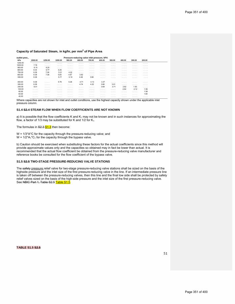
51
Capacity of Saturated Steam, in kg/hr, per mm2 of Pipe Area
outlet pres., Pressure-reducing valve inlet pressure, kPA kPa 1500.00 1250.00 1000.00 900.00 800.00 700.00 600.00 500.00 400.00 300.00 200.00 1250.00 . . . . . . . . . . . . . . . . . . . . . . . . . . . . . . . . . . . . . . . . . . . . . . . . . . . . . . .1000.00 7.78 . . . . . . . . . . . . . . . . . . . . . . . . . . . . . . . . . . . . . . . . . . . . . . . . . . 900.00 8.15 6.25 . . . . . . . . . . . . . . . . . . . . . . . . . . . . . . . . . . . . . . . . . . . . . 800.00 8.34 6.77 4.29 . . . . . . . . . . . . . . . . . . . . . . . . . . . . . . . . . . . . . . . . 700.00 8.38 7.06 5.21 4.22 . . . . . . . . . . . . . . . . . . . . . . . . . . . . . . . . . . . 600.00 8.38 7.08 5.65 4.87 3.82 . . . . . . . . . . . . . . . . . . . . . . . . . . . . . . 500.00 8.38 . . . . . 5.77 5.19 4.48 3.68 . . . . . . . . . . . . . . . . . . . . . . . .
400.00 8.38 . . . . . 5.78 5.26 4.71 4.13 3.37 . . . . . . . . . . . . . . . . . . . . 300.00 8.38 . . . . . . . . . . . . . . . 4.74 4.22 3.66 3.01 . . . . . . . . . . . . . . . 200.00 8.41 . . . . . . . . . . . . . . . . . . . . . . . . . 3.69 3.71 2.62 1.83 . . . . . 100.00 . . . . . . . . . . . . . . . . . . . . . . . . . . . . . . . . . . . . . . . . 2.64 2.12 1.56 80.00 . . . . . . . . . . . . . . . . . . . . . . . . . . . . . . . . . . . . . . . . . . . . . . . . . . 1.58 60.00 . . . . . . . . . . . . . . . . . . . . . . . . . . . . . . . . . . . . . . . . . . . . . . . . . . 1.60 40.00 . . . . . . . . . . . . . . . . . . . . . . . . . . . . . . . . . . . . . . . . . . . . . . . . . . . . . . .
Where capacities are not shown for inlet and outlet conditions, use the highest capacity shown under the applicable inlet pressure column. 6 S1.4 S2.4 STEAM FLOW WHEN FLOW COEFFICIENTS ARE NOT KNOWN a) It is possible that the flow coefficients K and K1 may not be known and in such instances for approximating the flow, a factor of 1/3 may be substituted for K and 1/2 for K1. The formulas in S2.3 S1.3 then become: W = 1/3*A*C for the capacity through the pressure-reducing valve; and W = 1/2*A1*C1 for the capacity through the bypass valve.
b) Caution should be exercised when substituting these factors for the actual coefficients since this method will provide approximate values only and the capacities so obtained may in fact be lower than actual. It is recommended that the actual flow coefficient be obtained from the pressure-reducing valve manufacturer and reference books be consulted for the flow coefficient of the bypass valve. S1.5 S2.5 TWO-STAGE PRESSURE-REDUCING VALVE STATIONS The safety pressure relief valve for two-stage pressure-reducing valve stations shall be sized on the basis of the highside pressure and the inlet size of the first pressure-reducing valve in the line. If an intermediate pressure line is taken off between the pressure-reducing valves, then this line and the final low side shall be protected by safety relief valves sized on the basis of the high-side pressure and the inlet size of the first pressure-reducing valve. See NBIC Part 1, Table S2.5 Table S1.5. TABLE S1.5 S2.5
Page 351 of 400
Page 351 of 400
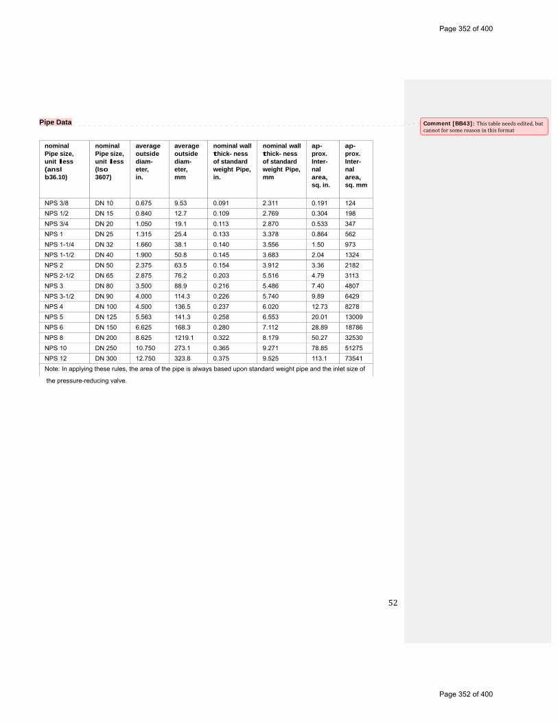
52
nominal Pipe size, unit less (ansI b36.10)
nominal Pipe size, unit less (Iso 3607)
average outside diam- eter, in.
average outside diam- eter, mm
nominal wall thick- ness of standard weight Pipe, in.
nominal wall thick- ness of standard weight Pipe, mm
ap- prox. Inter- nal area, sq. in.
ap- prox. Inter- nal area, sq. mm
NPS 3/8 DN 10 0.675 9.53 0.091 2.311 0.191 124
NPS 1/2 DN 15 0.840 12.7 0.109 2.769 0.304 198
NPS 3/4 DN 20 1.050 19.1 0.113 2.870 0.533 347
NPS 1 DN 25 1.315 25.4 0.133 3.378 0.864 562
NPS 1-1/4 DN 32 1.660 38.1 0.140 3.556 1.50 973
NPS 1-1/2 DN 40 1.900 50.8 0.145 3.683 2.04 1324
NPS 2 DN 50 2.375 63.5 0.154 3.912 3.36 2182
NPS 2-1/2 DN 65 2.875 76.2 0.203 5.516 4.79 3113
NPS 3 DN 80 3.500 88.9 0.216 5.486 7.40 4807
NPS 3-1/2 DN 90 4.000 114.3 0.226 5.740 9.89 6429
NPS 4 DN 100 4.500 136.5 0.237 6.020 12.73 8278
NPS 5 DN 125 5.563 141.3 0.258 6.553 20.01 13009
NPS 6 DN 150 6.625 168.3 0.280 7.112 28.89 18786
NPS 8 DN 200 8.625 1219.1 0.322 8.179 50.27 32530
NPS 10 DN 250 10.750 273.1 0.365 9.271 78.85 51275
NPS 12 DN 300 12.750 323.8 0.375 9.525 113.1 73541
Note: In applying these rules, the area of the pipe is always based upon standard weight pipe and the inlet size of
Pipe Data
the pressure-reducing valve.
Comment [BB43]: Thistableneedsedited,butcannotforsomereasoninthisformat
Page 352 of 400
Page 352 of 400
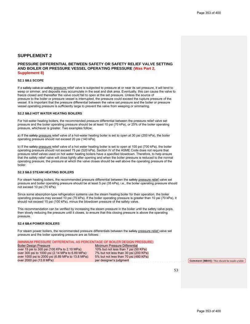
53
SUPPLEMENT 2 PRESSURE DIFFERENTIAL BETWEEN SAFETY OR SAFETY RELIEF VALVE SETTING AND BOILER OR PRESSURE VESSEL OPERATING PRESSURE (Was Part 2, Supplement 8) S2.1 S8.1 SCOPE If a safety valve or safety pressure relief valve is subjected to pressure at or near its set pressure, it will tend to weep or simmer, and deposits may accumulate in the seat and disk area. Eventually, this can cause the valve to freeze closed and thereafter the valve could fail to open at the set pressure. Unless the source of pressure to the boiler or pressure vessel is interrupted, the pressure could exceed the rupture pressure of the vessel. It is important that the pressure differential between the valve set pressure and the boiler or pressure vessel operating pressure is sufficiently large to prevent the valve from weeping or simmering. S2.2 S8.2 HOT WATER HEATING BOILERS For hot-water heating boilers, the recommended pressure differential between the pressure relief valve set pressure and the boiler operating pressure should be at least 10 psi (70 kPa), or 25% of the boiler operating pressure, whichever is greater. Two examples follow: a) If the safety pressure relief valve of a hot-water heating boiler is set to open at 30 psi (200 kPa), the boiler operating pressure should not exceed 20 psi (140 kPa).
b) If the safety pressure relief valve of a hot water heating boiler is set to open at 100 psi (700 kPa), the boiler operating pressure should not exceed 75 psi (520 kPa). Section IV of the ASME Code does not require that pressure relief valves used on hot water heating boilers have a specified blowdown. Therefore, to help ensure that the safety relief valve will close tightly after opening and when the boiler pressure is reduced to the normal operating pressure, the pressure at which the valve closes should be well above the operating pressure of the boiler. S2.3 S8.3 STEAM HEATING BOILERS For steam heating boilers, the recommended pressure differential between the safety pressure relief valve set pressure and boiler operating pressure should be at least 5 psi (35 kPa), i.e., the boiler operating pressure should not exceed 10 psi (70 kPa). Since some absorption-type refrigeration systems use the steam heating boiler for their operation, the boiler operating pressure may exceed 10 psi (70 kPa). If the boiler operating pressure is greater than 10 psi (70 kPa), it should not exceed 15 psi (100 kPa), minus the blowdown pressure of the safety valve. This recommendation can be verified by increasing the steam pressure in the boiler until the safety valve pops, then slowly reducing the pressure until it closes, to ensure that this closing pressure is above the operating pressure. S2.4 S8.4 POWER BOILERS For steam power boilers, the recommended pressure differentials between the safety pressure relief valve set pressure and the boiler operating pressure are as follows: (MINIMUM PRESSURE DIFFERENTIAL AS PERCENTAGE OF BOILER DESIGN PRESSURE) Boiler Design Pressure Minimum Pressure Differential over 15 psi to 300 psi (100 KPa to 2.10 MPa): 10% but not less than 7 psi (50 KPa) over 300 psi to 1000 psi (2.14 MPa to 6.89 MPa): 7% but not less than 30 psi (200 KPa) over 1000 psi to 2000 psi (6.89 MPa to 13.8 MPa): 5% but not less than 70 psi (480 KPa) over 2000 psi (13.8 MPa): per designer’s judgment
Comment [BB44]: Thisshouldbemadeatable
Page 353 of 400
Page 353 of 400

54
Notes: 1. Above 2000 psi (13.8 MPa) the pressure differential between operating pressure and the maximum allowable working pressure is a matter for the designer’s judgment , taking into consideration such factors as satisfactory operating experience and the intended service conditions.
2. Safety Pressure relief valves in hot water service are more susceptible to damage and subsequent leakage, than safety pressure relief valves relieving steam. It is recommended that the maximum allowable working pressure of the boiler and safety pressure relief valve setting for high-temperature hot-water boilers be selected substantially higher than the desired operating pressure, so as to minimize the time the safety pressure relief valve must lift.
3. For organic fluid vaporizers a pressure differential of 40 psi (280 kPa) is recommended. S2.5 S8.5 PRESSURE VESSELS Due to the variety of service conditions and the various designs of pressure relief valves, only general guidelines can be given regarding differentials between the set pressure of the valve and the operating pressure of the vessel. Operating difficulty will be minimized by providing an adequate differential for the application. The following is general advisory information on the characteristics of the intended service and of the pressure relief valves that may bear on the proper pressure differential selection for a given application. These considerations should be reviewed early in the system design since they may dictate the maximum allowable working pressure of the system.
To minimize operational problems it is imperative that the user consider not only normal operating conditions of the fluids (liquids or gases), pressures, and temperatures, but also start-up and shutdown conditions, process upsets, anticipated ambient conditions, instrument response time, and pressure surges due to quick-closing valves, etc. When such conditions are not considered, the pressure relief devices may become, in effect, a pressure controller, a duty for which they were not designed. Additional consideration should be given to the hazard and pollution associated with the release of the fluid. Larger differentials may be appropriate for fluids which are toxic, corrosive, or exceptionally valuable.
The blowdown characteristics and capabilities are the first consideration in selecting a compatible valve and operating margin. After a self-actuated release of pressure, the valve must be capable of reclosing above the normal operating pressure. For example: if the valve is set at 100 psi (700 kPa) with a 7% blowdown, it will close at 93 psi (640 kPa). The operating pressure must be maintained below 93 psi (640 kPa) in order to prevent leakage or flow from a partially open valve. Users should exercise caution regarding the blowdown adjustment of large, spring-loaded valves. Test facilities, whether owned by the manufacturer, repair house, or user, may not have sufficient capacity to accurately verify the blowdown setting. The setting cannot be considered accurate unless made in the field on an actual installation.
Pilot operated valves represent a special case from the standpoint of both blowdown and tightness. The pilot portion of some pilot operated valves can be set at blowdowns as short as 2%. This characteristic is not, however, reflected in the operation of the main valve in all cases. The main valve can vary considerably from the pilot depending on the location of the two components in the system. If the pilot is installed remotely from the main valve, significant time and pressure lags can occur, but reseating of the pilot ensures reseating of the main valve. The pressure drop in connecting piping between the pilot and the main valve must not be excessive, otherwise the operation of the main valve will be adversely affected.
Tightness capability is another factor affecting valve selection, whether spring-loaded or pilot operated. Tightness varies somewhat depending on whether metal or resilient seats are specified and also on such factors as corrosion and temperature. The required tightness and test method should be specified to comply at a pressure not lower than the normal operating pressure of the process. It should be remembered that any degree of tightness obtained should not be considered permanent. Service operation of a valve almost invariably reduces the degree of tightness.
Page 354 of 400
Page 354 of 400
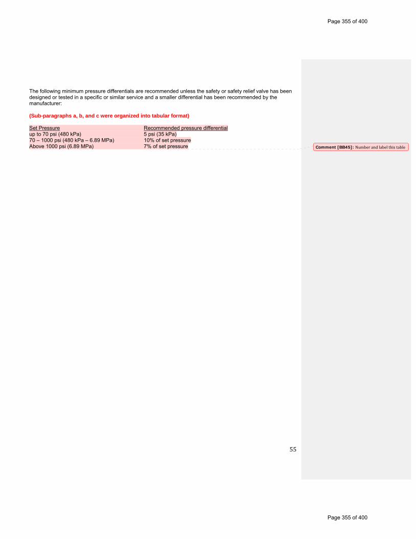
55
The following minimum pressure differentials are recommended unless the safety or safety relief valve has been designed or tested in a specific or similar service and a smaller differential has been recommended by the manufacturer:
(Sub-paragraphs a, b, and c were organized into tabular format) Set Pressure Recommended pressure differential up to 70 psi (480 kPa) 5 psi (35 kPa) 70 – 1000 psi (480 kPa – 6.89 MPa) 10% of set pressure Above 1000 psi (6.89 MPa) 7% of set pressure Comment [BB45]: Numberandlabelthistable
Page 355 of 400
Page 355 of 400
56
SUPPLEMENT 3 GUIDE TO JURISDICTIONS FOR AUTHORIZATION OF OWNERS-USERS TO MAKE ADJUSTMENTS TO PRESSURE RELIEF VALVES (WAS PART 3 S7.10) S3.1 S7.10.1 GENERAL The Jurisdiction may authorize properly trained and qualified employees of boiler and pressure vessel owners or users or their designees to confirm or restore set pressure shown on the unmodified original nameplate or stamping, or repair nameplate and/or performance of pressure relief valves. All external adjustments shall be resealed with a seal identifying the responsible organization and a metal tag that identifies the organization and the date the adjustment shall be installed. S3.2 S7.10.2 TRAINING a) The user shall establish a documented in house training program. This program shall establish training objectives and provide a method of evaluating the training effectiveness. As a minimum, training objectives for knowledge level shall include:
1) Applicable ASME Code and NBIC requirements;
2) Responsibilities within the organization’s quality system;
3) Knowledge of the technical aspects and mechanical skills for making set pressure and/or blowdown adjustments to pressure relief valves;
4) Knowledge of the technical aspects and mechanical skills for marking of pressure relief valve adjustments.
b) If the user established a designee, the designee shall establish a training program and make their documentation available to the user and the jurisdictional authority. S3.3 S7.10.3 DOCUMENTATION Each user shall document the evaluation and acceptance of an employee’s or designee’s qualifications. S3.4 S7.10.4 QUALITY SYSTEM a) A written quality system shall be established by either the user or the designee with a written description available to the jurisdictional authority.
b) The written description shall include at a minimum:
1) Calibration of Test Equipment: This shall describe a system for the calibration of measuring and test equipment. Documentation of these calibrations shall include the standard used and the results. Calibration standards shall be calibrated against the equipment having valid relationships to nationally recognized standards.
2) Valve Testing, Setting, and Sealing: This system shall include provisions that each valve shall be tested, set, and all external adjustments sealed according to the requirements of the applicable ASME Code section and NBIC Part 3, S7.10.1 a) S3.1.
3) Valve Marking: An effective marking system shall be established to ensure proper marking of the metal tag required by NBIC Part 3, S7.10.1 a) S3.1. The written quality system shall include a description or drawing of the metal tag. S3.5 S7.10.5 EXTERNAL ADJUSTMENTS
Page 356 of 400
Page 356 of 400
57
Only external adjustments to restore the set pressure shown on the unmodified original nameplate or stamping, or repair nameplate and/or performance of a pressure relief valve shall be made under the provisions of NBIC Part 3, S7.10.1 and NBIC Part 2, 2.5.7 S3.1 and 2.2.5. S3.6 S7.10.6 REPAIRS If disassembly, change of set pressure, or additional repairs are necessary, the valve shall be repaired by an organization that meets the requirements of the NBIC.
Page 357 of 400
Page 357 of 400

58
SUPPLEMENT 4 RECOMMENDED PROCEDURES FOR REPAIRING PRESSURE RELIEF VALVES (Was Supplement S7.14) S4.1 S7.14.1 INTRODUCTION a) It is essential that the repair organization establish basic, specific procedures for the repair of pressure relief valves. The purpose of these recommended procedures is to provide the repair organization with guidelines for this important aspect of valve repair. It is realized that there are many types of valves and conditions under which they are repaired and, for this reason, the specific items in these recommended procedures may not apply, or they may be inadequate for each of those types or to the detailed repairs that may be required for each valve.
b) NBIC Part 3, S7.14.2 S4.2 contains recommended procedures for the repair of spring-loaded pressure relief valves, and NBIC Part 3, S7.14.3 S4.3 contains recommended procedures for the repair of pilot operated types of safety relief valves. Information on Packaging, Shipping and Transportation is included as S4.5.
S4.2 S7.14.2 SPRING-LOADED PRESSURE RELIEF VALVES Prior to removal of a valve from a system for a repair or any disassembly, ensure that all sources of pressure have been removed from the valve.
a) Visual Inspection as Received
1) This information is to be recorded: a. Record user (customer) identification number;
b. Complete original PRV nameplate data, previous repair nameplate data, plus any important information received from customer;
c. Check external adjustment seals for warranty repair;
d. Check bonnet for venting on bellows type valves; and
e. Check appearance for any unusual damage, missing, or misapplied parts.
2) If sufficient damage or other unusual conditions are detected that may pose a safety risk during preliminary testing, then proceed directly to NBIC Part 3, S7.14.2 S4.2 c)
3) Valves that are to be repaired in place proceed to NBIC Part 3, S7.14.2 S4.2 c) unless preliminary testing has been authorized by the owner.
b) Preliminary Test as Received
1) Information from the recommended preliminary performance test and subsequent disassembly and inspections will provide a basis for any repair interval change that should be necessary to ensure that the valve will function as intended.
2) Determine set pressure or Cold Differential Test Pressure (CDTP) in accordance with manufacturer’s recommendations and appropriate ASME Code Section. Do not allow test pressure to exceed 116% of set pressure unless otherwise specified by the owner. A minimum of three tests is usually required to obtain consistent results.
Comment [BB46]: Thissectionneedssomeattention…eitherall“shall”languageneedstoberemovedbecauseitisonlyrecommendations,ormoreconsistentuseof“shall”languageneedstobeadded
Page 358 of 400
Page 358 of 400
59
3) If results do not correlate with field performance, then steps to duplicate field conditions (fluid and temperature) may be necessary.
4) Record preliminary test results and test bench identification data.
c) Disassembly
1) Remove cap and lever assembly, if applicable.
2) Remove release nut assembly, if applicable.
3) Loosen jam nut on adjusting (compression) screw.
4) Record measurement and remove adjusting (compression) screw.
5) Remove bonnet or yoke.
6) Remove spring and washers, and tag (identify) including upper and lower washers, as appropriate.
7) Remove spindle and disk assembly.
8) Remove ring pins.
9) Record measurement and remove adjusting rings, nozzle, and guide, as applicable.
d) Cleaning
1) Wire all small parts together and clean. (Caution: do not use a cleaning method that will damage the parts.)
2) Do not clean in a chemical solution except under acceptable circumstances.
3) Protect seating surfaces and nameplates prior to cleaning.
e) Inspection
1) Check spring for correct range, damage such as erosion, corrosion, cracking, or compression below free height.
2) Check nozzle for cracks (NDE as applicable) or unusual wear.
3) Check disk assembly for cracks (NDE as applicable) or unusual wear.
4) Check spindle for trueness, bearing areas, and thread condition.
5) Check guide for wear and galling.
6) Check adjusting ring(s) for worn threads and wear.
7) Check ring pins for bent or broken pin and thread condition.
8) Check bellows, if provided, for pinholes and corrosion.
9) Check flange gasket facings for wear and cuts.
f) Machining
Machine nozzle and disk as necessary to the manufacturer’s critical dimension charts.
Page 359 of 400
Page 359 of 400

60
g) Lapping
1) Machine or hand lap disk and nozzle to be sure of flatness.
2) Lap bevel seats to a grey finish; then re-machine disk or plug to the manufacturer’s critical dimension.
h) Bearing Points
Grind all bearing areas with grinding compound to make sure they are round and true.
i) Assembly 1. Install Nozzle 2. Install lower ring and guide ring to the measurement from c) 9) above or to manufacturer’s specifications. 3. Install guide 4. Install disc and holder 5. Install spindle 6. Install spring washers 7. Install bonnet 8. Install bonnet bolting 9. Install adjusting screw and lock nut to the measurement from c) 4) above, 10. Install release nut and lock nut, and cap and lever assembly, and 11. Document installation of replacement parts. j) Testing Test data shall be recorded. Testing will be done in accordance with manufacturer’s recommendations and appropriate ASME Code section. To preclude unsafe and unstable valve operations or erroneous performance test results, it is recommended that low volume testing equipment (e.g., gas cylinders without a test vessel, hand pumps, tubing) should be avoided.
k) Sealing After final adjusting and acceptance by quality control inspection, all external adjustments will shall be sealed with a safety seal providing a means of identification of the organization performing the repair.
l) Nameplate The repairer will place a repair nameplate on each repaired valve. The nameplate shall, as a minimum, meet the requirements of NBIC Part 3, 5.12.1 3.7.1.
m) Packaging, Shipping and Transportation (moved to the end of this section and combined with Part 2 info)
1) Valves should be securely fastened to pallets in the vertical position to avoid side loads on guiding surfaces.
2) Threaded and socket-weld valves up to 2 in. (50 mm) may be securely packaged and cushioned during transport.
3) Valve inlet and outlet connection, drain connections and bonnet vents should be protected during shipment and storage to avoid internal contamination of the valve. Ensure all covers and/or plugsare removed prior to installation.
4) Lifting levers should be wired or secured so they cannot be moved while the valve is being shipped or stored.
5) Valves for special services, including but not limited to oxygen, chlorine, and hydrogen peroxide, should be packaged in accordance with appropriate standards and/or owner procurement requirements.
Page 360 of 400
Page 360 of 400
61
S4.3 S7.14.3 PILOT OPERATED SAFETY RELIEF VALVES a) Visual Inspection as Received
1) This information is to be recorded: a. Complete nameplate data, plus any other important information received from the customer;
b. User identification number, if applicable;
c. Seals on external adjustments (yes/no, ensure seals are intact);
d. Identification on seal; and
e. Obvious damage and external condition including missing or misapplied parts.
b) Disassembly
1) Remove pilot and disassemble per manufacturer’s maintenance instruction.
2) Disassemble main valve. Where lift adjustments are provided, do not remove the locking device or change the lift unless it is required as part of conversion.
3) Remove the nozzle if recommended by the manufacturer’s maintenance instructions and/or when required as part of conversion.
c) Cleaning
1) Pilot — Components of pilot are small and must be handled carefully to prevent damage or loss. Clean parts and nameplates with solvents that will not affect the parent metal and/or polish with 500 grit paper.
2) Main Valve — Clean by appropriate means such as abrasive blast. Finishes of machined surfaces must not be affected. (Caution: Do not use a cleaning method that will damage the parts or nameplates.)
d) Inspection
1) Pilot
a. Check spring for damage such as corrosion, cracks, out of square ends, etc.
b. Inspect all parts for damage. Small burrs or scratches may be removed by polishing. Severely damaged parts should be replaced. (Internal components or pilots should not be repaired by machining as the functions of the pilot could easily be impaired.)
c. Check strainers and filters on inlet and outlet lines.
d. Replace all soft goods per manufacturer’s recommendation.
2) Main Valve
a. Check nozzle seating surface for nicks. These can be removed by machining or lapping as required.
b. Check the piston and liner (or other moving member) for galling or excessive wear. The piston should move freely in the liner.
c. Replace soft goods or re-lap disk as required.
Page 361 of 400
Page 361 of 400

62
d. Where lift adjustments are provided, measure the lift per the manufacturer’s specifications.
e) Testing Test data shall be recorded. Testing will be done in accordance with the manufacturer’s recommendation and in accordance with the applicable ASME Code section. To preclude unsafe and unstable valve operations or erroneous performance test results, it is recommended that low volume testing equipment (e.g., gas cylinders without a test vessel, hand pumps, tubing) should be avoided.
f) Sealing After final adjustment and acceptance by quality control, all external adjustments will shall be sealed by means assuring positive identification of the organization performing the repair.
g) Nameplate The repairer will place a repair nameplate on each repaired valve. The nameplate, as a minimum, shall meet the requirements of NBIC Part 3, 5.12.1 3.7.1. S4.4 2.5.6 PACKAGING, SHIPPING AND TRANSPORTATION OF PRESSURE RELIEF DEVICES
a) The improper packaging, shipment, and transport of pressure relief devices can have detrimental effects on device operation. Pressure relief devices should be treated with the same precautions as instrumentation, with care taken to avoid rough handling or contamination prior to installation.
b) The following practices are recommended: 1) Valves should be securely fastened to pallets in the vertical position to avoid side loads on guiding surfaces except threaded and socket-weld valves up to NPS 2 (DN 50 50mm) may be securely packaged and cushioned during transport.
2) Valve inlet and outlet connection, drain connections, and bonnet vents should be protected during shipment and storage to avoid internal contamination of the valve. Ensure all covers and/or plugs are removed prior to installation.
3) The valve should not be picked up or carried using the lifting lever. Lifting levers should be wired or secured so they cannot be moved while the valve is being shipped or stored. These wires shall be removed before the valve is placed in service.
4) Pilot valve tubing should be protected during shipment and storage to avoid damage and/or breakage. h) Packaging, Shipping and Transportation
1) Valves should be securely fastened to pallets in the vertical position to avoid side loads on guiding surfaces.
2) Threaded and socket-weld valves up to 2 in. (50 mm) may be securely packaged and cushioned during transport.
3) Valve inlet and outlet connection and drain connections should be protected during shipment and storage to avoid internal contamination of the valve. Ensure all covers and/or plugs are removed
prior to installation.
4) Lifting levers should be wired or secured so they cannot be moved while the valve is being shipped or stored.
5) Tubing should be protected during shipment and storage to avoid damage and/or breakage.
Page 362 of 400
Page 362 of 400

63
6) 5)Valves for special services, including but not limited to oxygen, chlorine, and hydrogen peroxide, should be packaged in accordance with appropriate standards and/or owner procurement requirements.
Page 363 of 400
Page 363 of 400
64
SUPPLEMENT 5 RECOMMENDED GUIDE FOR THE DESIGN OF A TEST SYSTEM FOR PRESSURE RELIEF DEVICES IN COMPRESSIBLE FLUID SERVICE (Was Part 3, Supplement 8) S5.1 S8.1 INTRODUCTION This supplement provides guidance for the design of a test system using compressible fluids (e.g., steam or air/gas) and permits the determination of pressure relief valve set pressure and valve operating characteristics such as blowdown. The size of the test vessel needed depends on the size of the valve, its set pressure, the design of the test system, and whether blowdown must be demonstrated. A repair organization may use the information provided in this supplement to determine the minimum size test vessel needed so that the measured performance is characteristic of the valve and not the test system. S5.2 S8.2 GENERAL a) The National Board administrative rules and procedures for the “VR” Certificate of Authorization and symbol stamp require that pressure relief valves, after repair, be tested in accordance with the manufacturer’s recommendations and the applicable ASME Code. The purpose of this testing is to provide reasonable assurance that valves will perform according to design when they are returned to service.
b) It is recognized that a full evaluation of the performance of some pressure relief valve designs requires testing at maximum allowable overpressure. However, it is beyond the scope of this supplement to define test equipment or facilities for such testing.
c) NBIC Part 3 Section 9 Section 6 of this part provides a glossary, NBIC Part 3, S38.3 S5.3 describes typical test equipment, and NBIC Part 3, S38.4 S5.4 provides data for estimating the size of test vessels required. S5.3 S8.3 TEST SYSTEM DESCRIPTION a) An optimum configuration, particularly when the test medium source is of small capacity, is shown in NBIC Part 3, Figure S8.3-a Figure S5.3-a. The test medium flows from the pressure source, usually a compressor or boiler, to an accumulator. It then flows through a pressure-controlling valve into the test vessel, from which it is discharged, through the pressure relief valve installed mounted on the test vessel. The pressure-controlling valve is usually a globe valve, although any throttling valve is acceptable. If the pressure-controlling valve is of adequate size and can open quickly, large transient flows can be generated, increasing the pressure above the pressure relief valve set pressure, causing it to lift, and be sustained in its lifted condition.
b) NBIC Part 3, Figure S8.3-b Figure S5.3-b shows a simpler test system in which the test vessel is pressurized directly from the pressure source without the use of an accumulator. In this configuration, flow-rates through the pressure relief valve and any consequent over-pressure are dependent on the flow generating capacity of the pressure source.
c) In a test facility, the pressure relief valve is usually installed mounted on an isolating valve that should be of sufficient size that it will not choke flow to the pressure relief valve. There should be no intervening piping between the two valves to avoid any significant pressure drop between the test vessel and the pressure relief valve.
d) The isolating valve and any adapter flanges or valve test nozzles must be designed to sustain pressure relief valve discharge forces, and so secured that these forces are not transmitted to the test vessel. This is especially important for larger valves set at pressures greater than 100 psig (700 kPa). e) The vessel should have a length-to-diameter ratio as low as is practical, and should be suitably anchored.
f) Pressure sensing lines should be connected to the test vessel well away from any inlet or outlet connections where pressure distortions due to transient changes in flow velocity during testing could cause erroneous
Page 364 of 400
Page 364 of 400
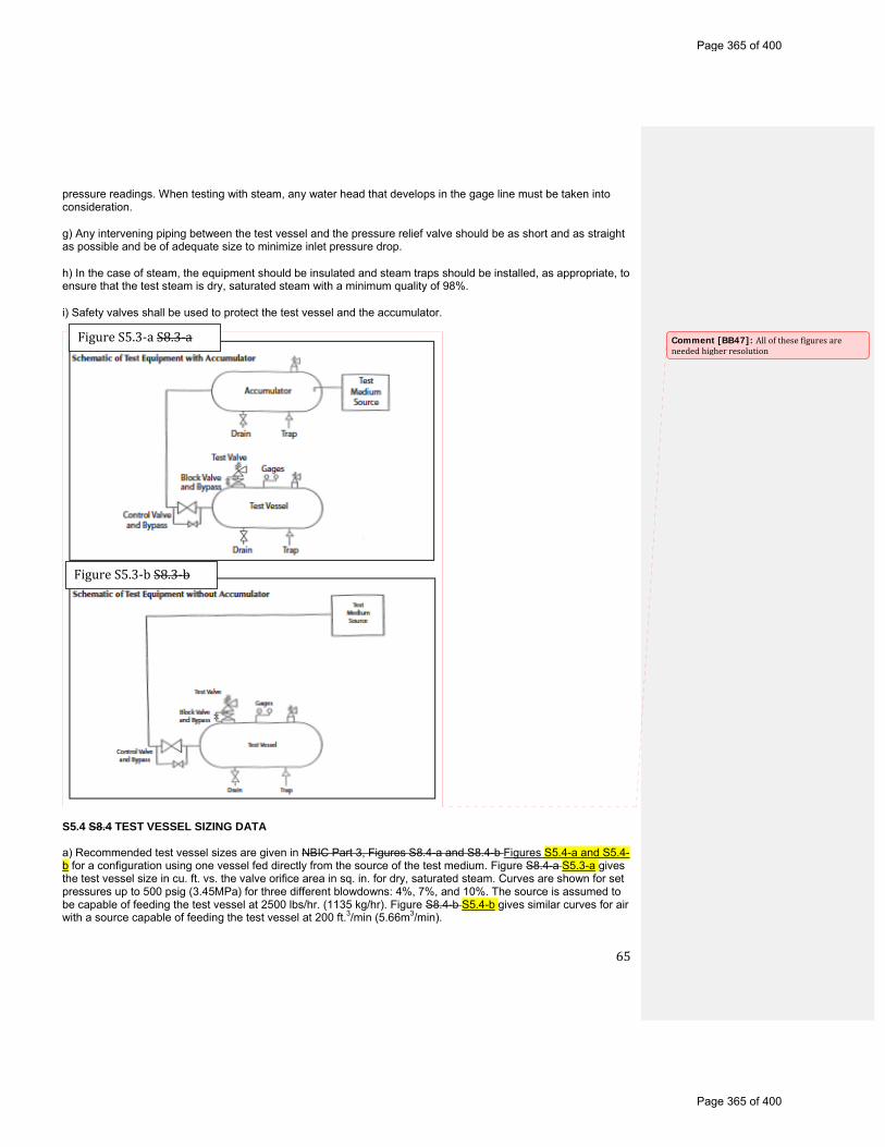
65
pressure readings. When testing with steam, any water head that develops in the gage line must be taken into consideration.
g) Any intervening piping between the test vessel and the pressure relief valve should be as short and as straight as possible and be of adequate size to minimize inlet pressure drop.
h) In the case of steam, the equipment should be insulated and steam traps should be installed, as appropriate, to ensure that the test steam is dry, saturated steam with a minimum quality of 98%.
i) Safety valves shall be used to protect the test vessel and the accumulator.
S5.4 S8.4 TEST VESSEL SIZING DATA a) Recommended test vessel sizes are given in NBIC Part 3, Figures S8.4-a and S8.4-b Figures S5.4-a and S5.4-b for a configuration using one vessel fed directly from the source of the test medium. Figure S8.4-a S5.3-a gives the test vessel size in cu. ft. vs. the valve orifice area in sq. in. for dry, saturated steam. Curves are shown for set pressures up to 500 psig (3.45MPa) for three different blowdowns: 4%, 7%, and 10%. The source is assumed to be capable of feeding the test vessel at 2500 lbs/hr. (1135 kg/hr). Figure S8.4-b S5.4-b gives similar curves for air with a source capable of feeding the test vessel at 200 ft.3/min (5.66m3/min).
FigureS5.3‐aS8.3‐a
FigureS5.3‐bS8.3‐b
Comment [BB47]: Allofthesefiguresareneededhigherresolution
Page 365 of 400
Page 365 of 400
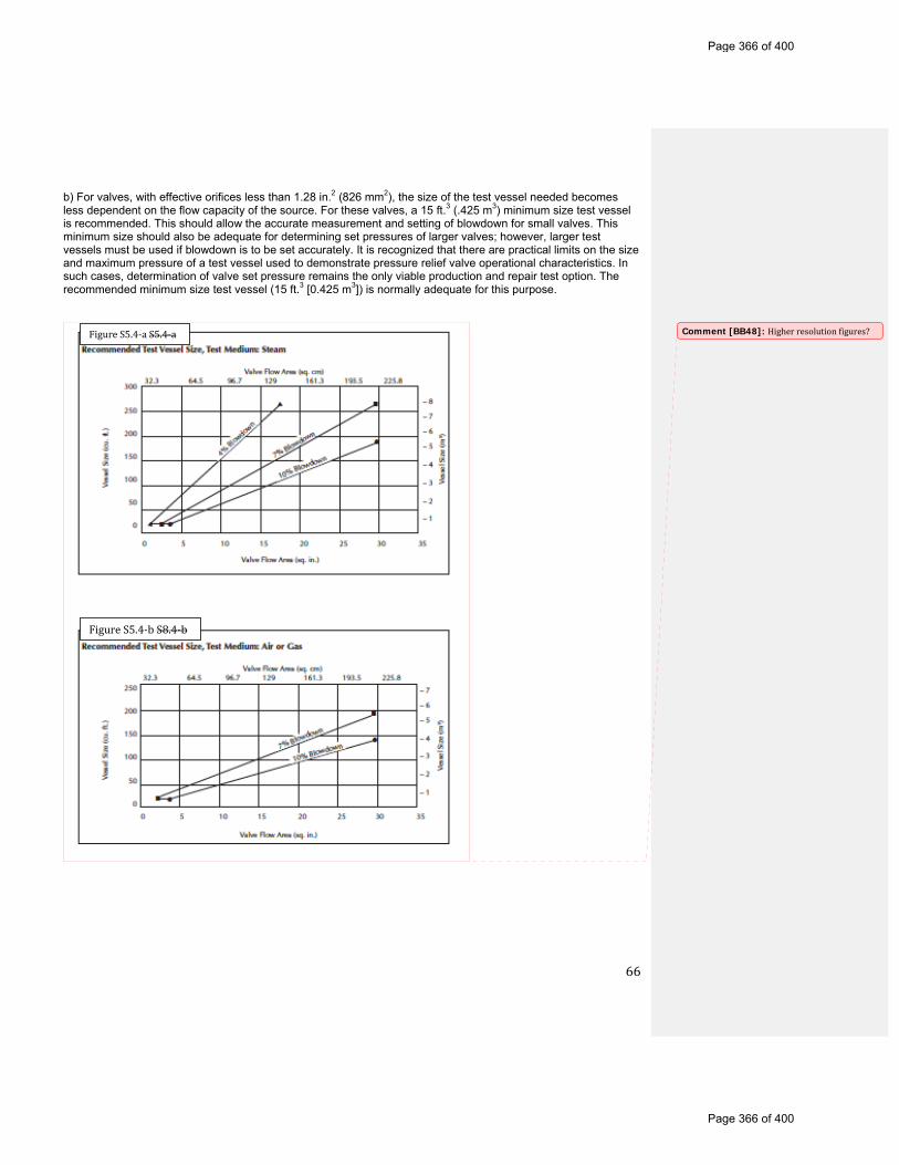
66
b) For valves, with effective orifices less than 1.28 in.2 (826 mm2), the size of the test vessel needed becomes less dependent on the flow capacity of the source. For these valves, a 15 ft.3 (.425 m3) minimum size test vessel is recommended. This should allow the accurate measurement and setting of blowdown for small valves. This minimum size should also be adequate for determining set pressures of larger valves; however, larger test vessels must be used if blowdown is to be set accurately. It is recognized that there are practical limits on the size and maximum pressure of a test vessel used to demonstrate pressure relief valve operational characteristics. In such cases, determination of valve set pressure remains the only viable production and repair test option. The recommended minimum size test vessel (15 ft.3 [0.425 m3]) is normally adequate for this purpose.
FigureS5.4‐aS5.4‐a
FigureS5.4‐bS8.4‐b
Comment [BB48]: Higherresolutionfigures?
Page 366 of 400
Page 366 of 400

67
SUPPLEMENT 6 PROCEDURES TO EXTEND THE “VR” CERTIFICATE OF AUTHORIZATION AND STAMP TO ASME “NV” STAMPED PRESSURE RELIEF DEVICES (Was part 3, suppl. 9) S6.1 S9.1 INTRODUCTION Approval to extend the scope of the National Board “VR” Certificate of Authorization to the Certificate Holder to use the “VR” stamp on ASME Code “NV” Class 1, 2, or 3 stamped pressure relief devices, which have been capacity certified by the National Board, may be given subject to the provisions that follow. S6.2 S9.2 ADMINISTRATIVE PROCEDURES
a) The repair organization shall hold a valid “VR” Certificate of Authorization.
b) The repair organization shall obtain a National Board “NR” Certificate of Authorization and stamp. The requirements for said certificate and stamp include, but are not limited to, the following. The repair organization shall:
1) Maintain a documented quality assurance program that meets the applicable requirements of NBIC Part 3, 1.8. This program shall also include all the applicable requirements for the use of the “VR” stamp;
2) Have a contract or agreement with an Inspection Agency to provide inspection of repaired “NV”-stamped pressure relief devices by Inspectors who have been qualified in accordance with the requirements of ASME QAI-1, Qualifications for Authorized Inspection;
3) Successfully complete a survey of the quality assurance program and its implementation. This survey shall be conducted by representatives of the National Board, the Jurisdiction wherein the applicant’s repair facilities are located, and the applicant’s Authorized Inspection Agency. Further verification of such implementation by the survey team may not be necessary if the applicant holds a valid ASME “NV” certificate and can verify by documentation the capability of implementing the quality assurance program for repair of “NV”-stamped pressure relief devices, covered by the applicant’s ASME “NV” certificate.
c) The application of the “NR” Certificate of Authorization and stamp shall clearly define the scope of intended activities with respect to the repair of Section III, “NV”- stamped pressure relief devices.
d) Revisions to the quality assurance program shall be acceptable to the Authorized Nuclear Inspector Supervisor and the National Board before being implemented.
e) The scope of the “VR” Certificate of Authorization shall include repair of “NV”-stamped pressure relief devices.
f) Verification testing of valves repaired by the applicant shall not be required provided such testing has been successfully completed under the applicant’s “VR” certification program.
g) A survey of the applicant for the “VR” Certificate of Authorization and endorsement of the repair of “NV”-stamped pressure relief devices may be made concurrently. S6.3 S9.3 GENERAL RULES a) ASME Code Section III, “NV”-stamped pressure relief devices, which have been repaired in accordance with these rules, shall be stamped with both the “VR” and “NR” stamps.
b) The “VR” and “NR” stamps shall be applied only to “NV” stamped (Class 1, 2, or 3) National Board capacity certified pressure relief devices that have been disassembled, inspected, and repaired as necessary, such that the valves’ condition and performance are equivalent to the standards for new valves.
c) All measuring and test equipment used in the repair of pressure relief devices shall be calibrated against
Page 367 of 400
Page 367 of 400
68
certified equipment having known valid relationships to nationally recognized standards.
d) Documentation of the repair of “NV” stamped pressure relief devices shall be recorded on the National Board Form NVR-1, Report of Repair/ Replacement Activities for Nuclear Pressure Relief Devices, in accordance with the requirements of NBIC Part 3, 1.8.
e) When an ASME “NV”-stamped pressure relief device requires a duplicate nameplate because the original nameplate is illegible or missing, it may be applied using the procedures of NBIC Part 3, 5.12.5 3.7.5 provided concurrence is obtained from the Authorized Nuclear Inspector and Jurisdiction. In this case the nameplate shall be marked “SEC. III” to indicate the original ASME Code stamping.
Page 368 of 400
Page 368 of 400
69
PART 4, SECTION 4 PART 1, SECTION 7 INSTALLATION — NBIC POLICY FOR METRICATION 4.1 7.1 GENERAL This policy provides guidance for the use of US customary units and metric units. Throughout the NBIC, metric units are identified and placed in parentheses after the US customary units referenced in the text and associated tables. In Parts 2 and 3, Supplement 6, Continued Service and Inspection of DOT Transport Tanks the metric units are shown first with U.S. Customary units shown in parentheses. For each repair or alteration performed, selection of units shall be based on the units used in the original code of construction. For example, items constructed using US customary units shall be repaired or altered using US customary units. The same example applies to items constructed using metric units. Whichever units are selected, those units are to be used consistently throughout each repair or alteration. Consistent use of units includes all aspects of work required for repairs or alterations (i.e. materials, design, procedures, testing, documentation, and stamping, etc.). 4.2 7.2 EQUIVALENT RATIONALE The rationale taken to convert metric units and US customary units involves knowing the difference between a soft conversion and a hard conversion. A soft conversion is an exact conversion. A hard conversion is simply performing a soft conversion and then rounding off within a range of intended precision. When values specified in the NBIC are intended to be approximate values, a hard conversion is provided. If an exact value is needed to maintain safety or required based on using good engineering judgment, then a soft conversion will be used. In general, approximate accuracy is acceptable for most repairs or alterations performed using the requirements of the NBIC. Therefore, within the NBIC, metric equivalent units are primarily hard conversions. The following examples are provided for further clarification and understanding of soft conversions versus hard conversions: Example 1: Using 1 in. = 25.4 mm; 12 in. = 304.8 mm (soft conversion) Example 2: Using the above conversion, a hard conversion may be 300 mm or 305 mm depending on the degree of precision needed. 4.3 7.3 PROCEDURE FOR CONVERSION The following guidelines shall be used to convert between US customary units and metric units within the text of the NBIC: a) All US customary units will be converted using a soft conversion;
b) Soft conversion calculations will be reviewed for accuracy;
c) Based on specified value in the NBIC, an appropriate degree of precision shall be identified;
d) Once the degree of precision is decided, rounding up or down may be applied to each soft conversion in order to obtain a hard conversion; and
e) Use of hard conversion units shall be used consistently throughout the NBIC wherever soft conversions are not required.
Note: Care shall be taken to minimize percentage difference between units. 4.4 7.4 REFERENCING TABLES
Page 369 of 400
Page 369 of 400

70
The following tables are provided for guidance and convenience when converting between US customary units and metric units. See NBIC Part 1, Tables 7.4-1 through 7.4-8 Tables 4.4-1 through 4.4-8. Temperature shall be converted to within 1°C as shown in NBIC Part 1, Table 7.4-2 Table 4.4-2. Fractions of an inch shall be converted according to NBIC Part 1, Table 7.4-3 Table 4.4.3. Even increments of inches are in even multiples of 25 mm. For example, 40 inches is equivalent to 1000 mm. Intermediate values may be interpolated rather than converting and rounding to the nearest mm. For nominal pipe sizes, the following relationships were used as shown in NBIC Parts 1, 2 or 3, Table 7.4-4 4.4-4 Areas in square inches (in2) were converted to square mm (mm2) and areas in square feet (ft2) were converted to square meters (m2). See examples in NBIC Parts 1, 2 or 3 Tables 7.4-5a and 7.4-5b Tables 4.4-5a and 4.4-5b Volumes in cubic inches (in. 3) were converted to cubic mm (mm3) and volumes in cubic feet (ft3) were converted to cubic meters (m3). See examples in NBIC Parts 1, 2 or 3, Tables 7.4-6a and 7.4-6b. Tables 4.4-6a and 4.4-6b. Although the pressure should always be in MPa for calculations, there are cases where other units are used in the text. For example, kPa is used for small pressures. Also, rounding was to two significant figures. See examples in Table 7.4-7 4.4-7 (Note that 14.7 psi converts to 101 kPa, while 15 psi converts to 100 kPa. While this may seem at first glance to be an anomaly, it is consistent with the rounding philosophy.) Material properties that are expressed in psi or ksi (e.g., allowable stress, yield and tensile strength, elastic modulus) were generally converted to MPa to three significant figures. See example in NBIC Parts 1, 2 or 3, Table 7.4-8 4.4-8. An often seen metric pressure rating is the expression BAR, one BAR equals 14.5 psi — to convert psi rating to a BAR rating, multiply by 0.069. SECTION 7 TABLE 4.4-1 7.4.1 US Fractions/Metric Equivalents Inches Millimeters 1/32 0.8 3/64 1.2 1/16 1.5 3/32 2.5 1/8 3 5/32 4 3/16 5 7/32 5.5 1/4 6 5/16 8 3/8 10 7/16 11 1/2 13 9/16 14 5/8 16 11/16 17 3/4 19 7/8 22 1 25 TABLE 4.4-2 7.4.2 Soft Conversion Factors (US x Factor = Metric) US Customary Metric Factor in. mm 25.4 ft. m 0.3048 in. 2 mm2 645.16
Page 370 of 400
Page 370 of 400

71
ft. 2 m2 0.09290304 in. 3 mm3 16,387.064 ft. 3 m3 0.02831685 US gal. m3 0.003785412 US gal. liters 3.785412 psi MPa 0.0068948 psi kPa 6.894757 ft-lb J 1.355818 °F °C 5/9 x (°F–32) R K 5/9 lbm kg 0.4535924 lbf N 4.448222 in.-lb N-mm 112.98484 ft.-lb N-m 1.3558181 ksi√in MPa√m 1.0988434 Btu/hr W 0.2930711 lb/ft3 kg/m3 16.018463 in.-wc kPa 0.249089 Note: The actual pressure corresponding to the height of a vertical column of fluid depends on the local gravitational field and the density of the fluid, which in turn depends upon the temperature. This conversion factor is the conventional value adopted by ISO. The conversion assumes a standard gravitational field (gn – 9.80665 N/kg) and a density of water equal to 1,000 kg/m3. TABLE 4.4-3 7.4.3 Temperature Equivalents Temperature °F Temperature °C 60 16 70 21 100 38 120 49 350 177 400 204 450 232 800 427 1150 621 TABLE 4.4-4 7.4.4 Pipe Sizes/Equivalents US Customary Practice Metric Practice NPS 1/8 DN 6 NPS 1/4 DN 8 NPS 3/8 DN 10 NPS 1/2 DN 15 NPS 3/4 DN 20 NPS 1 DN 25 NPS 1-1/4 DN 32 NPS 1-1/2 DN 40 NPS 2 DN 50 NPS 2-1/2 DN 65 NPS 3 DN 80 NPS 3-1/2 DN 90 NPS 4 DN 100 NPS 5 DN 125 NPS 6 DN 150 NPS 8 DN 200 NPS 10 DN 250
Page 371 of 400
Page 371 of 400
72
NPS 12 DN 300 NPS 14 DN 350 NPS 16 DN 400 NPS 18 DN 450 NPS 20 DN 500 NPS 22 DN 550 NPS 24 DN 600 NPS 26 DN 650 NPS 28 DN 700 NPS 30 DN 750 NPS 32 DN 800 NPS 34 DN 850 NPS 36 DN 900 NPS 38 DN 950 NPS 40 DN 1000 NPS 42 DN 1050 NPS 44 DN 1100 NPS 46 DN 1150 NPS 48 DN 1200 NPS 50 DN 1250 NPS 52 DN 1300 NPS 54 DN 1350 NPS 56 DN 1400 NPS 58 DN 1450 NPS 60 DN 1500 Table 4.4-5a 7.4.5-a Area (US Customary) Area (Metric) 3 in2 650 mm2 6 in2 3,900 mm2 10 in2 6,500 mm2 Table 4.4-5b 7.4.5-b Area (US Customary) Area (Metric) 5 ft2 0.46 mm2 Table 4.4-6a 7.4.6-a Area (US Customary) Area (Metric) 1 in3 16,000 mm3 6 in3 96,000 mm3 10 in3 160,000 mm3 Table 4.4-6b 7.4.6b Area (US Customary) Area (Metric) 5 ft3 0.14 m3 TABLE 4.4-7 7.4.7 Pressure/Equivalents Pressure (US Customary) Pressure (Metric) 0.5 psi 3 kPa 2 psi 15 kPa 3 psi 20 kPa 10 psi 70 kPa 15 psi 100 kPa 30 psi 200 kPa 50 psi 350 kPa 100 psi 700 kPa 150 psi 1.03 MPa
Page 372 of 400
Page 372 of 400
73
200 psi 1.38 MPa 250 psi 1.72 MPa 300 psi 2.10 MPa 350 psi 2.40 MPa 400 psi 2.76 MPa 500 psi 3.45 MPa 600 psi 4.14 MPa 1,200 psi 8.27 MPa 1,500 psi 1 0.34 MPa Table 4.4-8 7.4.8 Strength (US Customary) Strength (Metric) 95,000 psi 655 MPa SECTION 8
Page 373 of 400
Page 373 of 400

74
PART 4, SECTION 5 PART 3, SECTION 8 PRESSURE RELIEF DEVICES — PREPARATION OF TECHNICAL INQUIRIES TO THE NATIONAL BOARD INSPECTION CODE COMMITTEE 5.1 8.1 INTRODUCTION The NBIC Committee meets regularly to consider written requests for interpretations and revisions to the Code rules. This section provides guidance to Code users for submitting technical inquiries to the Committee. Technical inquires include requests for additions to the Code rules and requests for Code Interpretations, as described below. a) Code Revisions Code revisions are considered to accommodate technological developments, address administrative requirements, or to clarify Code intent.
b) Code Interpretations Code Interpretations provide clarification of the meaning of existing rules in the Code, and are also presented in question and reply format. Interpretations do not introduce new requirements. In cases where existing Code text does not fully convey the meaning that was intended, and revision of the rules is required to support an Interpretation, an intent Interpretation will be issued and the Code will be revised. As a matter of published policy, the National Board does not approve, certify, or endorse any item, construction, propriety device or activity and, accordingly, inquiries requiring such consideration will be returned. Moreover, the National Board does not act as a consultant on specific engineering problems or on the general application or understanding of the Code rules. Inquiries that do not comply with the provisions of this Section or that do not provide sufficient information for the Committee’s full understanding may result in the request being returned to the inquirer with no action. 5.2 8.2 INQUIRY FORMAT Inquiries submitted to the Committee shall include: a) Purpose Specify one of the following:
1) revision of present Code rules;
2) new or additional Code rules; or
3) Code Interpretation.
b) Background Provide concisely the information needed for the Committee’s understanding of the inquiry, being sure to include reference to the applicable Code Edition, Addenda, paragraphs, figures, and tables. Provide a copy of the specific referenced portions of the Code.
c) Presentations The inquirer may attend a meeting of the Committee to make a formal presentation or to answer questions from the Committee members with regard to the inquiry. Attendance at a Committee meeting shall be at the expense of the inquirer. The inquirer’s attendance or lack of attendance at a meeting shall not be a basis for acceptance or rejection of the inquiry by the Committee. 5.3 8.3 CODE REVISIONS OR ADDITIONS Request for Code revisions or additions shall provide the following:
Page 374 of 400
Page 374 of 400

75
a) Proposed Revisions or Additions For revisions, identify the rules of the Code that require revision and submit a copy of the appropriate rules as they appear in the Code, marked up with the proposed revision. For additions, provide the recommended wording referenced to the existing Code rules.
b) Statement of Need Provide a brief explanation of the need for the revision or addition.
c) Background Information Provide background information to support the revision or addition, including any data or changes in technology that form the basis for the request that will allow the Committee to adequately evaluate the proposed revision or addition. Sketches, tables, figures, and graphs should be submitted as appropriate. When applicable, identify any pertinent paragraph in the Code that would be affected by the revision or addition and identify paragraphs in the Code that reference the paragraphs that are to be revised or added. 5.4 8.4 CODE INTERPRETATIONS Requests for Code Interpretations shall provide the following: a) Inquiry Provide a condensed and precise question, omitting superfluous background information and, when possible, composed in such a way that a “yes” or a “no” reply, with brief provisos if needed, is acceptable. The question should be technically and editorially correct.
b) Reply Provide a proposed reply that will clearly and concisely answer the inquiry question. Preferably the reply should be “yes” or “no” with brief provisos, if needed.
c) Background Information Provide any background information that will assist the Committee in understanding the proposed Inquiry and Reply Requests for Code Interpretations must be limited to an interpretation of the particular requirement in the Code. The Committee cannot consider consulting type requests such as:
1) A review of calculations, design drawings, welding qualifications, or descriptions of equipment or Parts to determine compliance with Code requirements;
2) A request for assistance in performing any Code-prescribed functions relating to, but not limited to, material selection, designs, calculations, fabrication, inspection, pressure testing, or installation;
3) A request seeking the rationale for Code requirements. SECTION 8 5.5 8.5 SUBMITTALS Submittals to and responses from the Committee shall meet the following criteria: a) Submittal Inquiries from Code users shall be in English and preferably be submitted in typewritten form; however, legible handwritten inquiries will be considered. They shall include the name, address, telephone number, fax number, and email address, if available, of the inquirer and be mailed to the following address: Secretary, NBIC Committee The National Board of Boiler and Pressure Vessel Inspectors 1055 Crupper Avenue Columbus, OH 43229 As an alternative, inquiries may be submitted via fax or email to:
Page 375 of 400
Page 375 of 400

76
Secretary NBIC Committee Fax: 614.847.1828 Email: [email protected] b) Response The Secretary of the NBIC Committee shall acknowledge receipt of each properly prepared inquiry and shall provide a written response to the Inquirer upon completion of the requested action by the NBIC Committee.
Page 376 of 400
Page 376 of 400
77
PART 4, SECTION 6 (SELECTIONS FROM PART 3, SECTION 9) PRESSURE RELIEF DEVICES — GLOSSARY OF TERMS 6.1 9.1 DEFINITIONS For the purpose of applying the rules of the NBIC, the following terms and definitions shall be used herein as applicable to each Part: Additional terms and definitions specific to DOT Transport Tanks are defined in Part 2, Supplement 6. Accumulator — A vessel in which the test medium is stored or accumulated prior to its use for testing. Alteration — A change in the item described on the original Manufacturer’s Data Report which affects the pressure containing capability of the pressure-retaining item. (See Part 3, 3.4.3, EXAMPLES OF ALTERATION) Nonphysical changes such as an increase in the maximum allowable working pressure (internal or external), increase in design temperature, or a reduction in minimum temperature of a pressure-retaining item shall be considered an alteration. ANSI — The American National Standards Institute Appliance — A piece of equipment that includes all controls, safety devices, piping, fittings, and vessel(s) within a common frame or enclosure that is listed and labeled by a nationally recognized testing agency for its intended use. ASME Code — The American Society of Mechanical Engineers’ Boiler and Pressure Vessel Code published by that Society, including addenda and Code Cases, approved by the associated ASME Board. Assembler — An organization that purchases or receives from a manufacturer the necessary component parts of valves and assembles, adjusts, tests, seals, and ships safety or safety relief valves at a geographical location, and using facilities other than those used by the manufacturer. Authorized Inspection Agency — New Construction: An Authorized Inspection Agency is one that is accredited by the National Board meeting the qualification and duties of NB-360, Criteria for Acceptance of Authorized Inspection Agencies for New Construction. Inservice: An Authorized Inspection Agency is either: a) a jurisdictional authority as defined in the National Board Constitution; or
b) an entity that is accredited by the National Board satisfying the requirements of NB-369, Qualifications and Duties for Authorized Inspection Agencies Performing Inservice Inspection Activities and Qualifications for Inspectors of Boilers and Pressure Vessels; NB-371, Accreditation of Owner-User Inspection Organizations (OUIO) or NB-390, For Federal Inspection Agencies (FIAs) Performing Inservice Inspection Activities. Biomass — Fuels which result from biological sources requiring a relatively short time for replenishment: Wood and bagasse are typical examples. Boiler — A boiler is a closed vessel in which water or other liquid is heated, steam or vapor generated, steam or vapor is superheated, or any combination thereof, under pressure for use external to itself, by the direct application of energy from the combustion of fuels or from electricity or solar energy. The term boiler also shall include the apparatus used to generate heat and all controls and safety devices associated with such apparatus or the closed vessel.
1) Power Boiler — a boiler in which steam or other vapor is generated at a pressure in excess of
Comment [BB49]: DoweneedtoaddanytermsrelatingtoPRDs?
Page 377 of 400
Page 377 of 400
78
15 psig (100 kPa) for use external to itself. The term power boiler includes fired units for vaporizing liquids other than water, but does not include fired process heaters and systems. (See also High- Temperature Water Boiler).
2) High-Temperature Water Boiler — a power boiler in which water is heated and operates at a pressure in excess of 160 psig (1.1 MPa) and/or temperature in excess of 250°F (121°C).
3) Steam Heating Boiler — A steam boiler installed to operate at pressures not exceeding 15 psig (100 kPa).
4) Hot-Water Heating Boiler — A hot water boiler installed to operate at pressures not exceeding 160 psig (1100 kPa) and/or temperatures not exceeding 250QF (121 Qq, at or near the boiler outlet.
5) Hot-Water Supply Boiler — a boiler that furnishes hot water to be used externally to itself at a pressure less than or equal to 160 psig (1 100 kPa gage) or a temperature less than or equal to 250QF (120QC) at or near the boiler outlet Capacity Certification — The verification by the National Board that a particular valve design or model has successfully completed all capacity testing as required by the ASME Code. Carbons Recycle — See Flyash Recycle Chimney or Stack — A device or means for providing the venting or escape of combustion gases from the operating unit. Confined Space –– Work locations considered “confined” because their configurations hinder the activities of employees who must enter, work in and exit them. A confined space has limited or restricted means for entry or exit, and it is not designed for continuous employee occupancy. Confined spaces include, but are not limited to, underground vaults, tanks, storage bins, manholes, pits, silos, process vessels, and pipelines. Regulatory Organizations often use the term “permit-required confined space” (permit space) to describe a confined space that has one or more of the following characteristics: contains or has the potential to contain a hazardous atmosphere; contains a material that has the potential to engulf an entrant; has walls that converge inward or floors that slope downward and taper into a smaller area which could trap or asphyxiate an entrant; or contains any other recognized safety or health hazard, such as unguarded machinery, exposed live wires, or heat stress. Confined space entry requirements may differ in many locations and the Inspector is cautioned of the need to comply with local or site- specific confined space entry requirements. Conversion — Pressure Relief Devices: The change of a pressure relief valve from one capacity-certified configuration to another by use of manufacturer’s instructions. Units of Measure: Changing the numeric value of a parameter from one system of units to another. Demonstration — Making evident by illustration, explanation, and completion of tasks documenting evaluation of an applicant’s ability to perform Code activities, including the adequacy of the applicant’s quality program, and by a review of the implementation of that program at the address of record and/or work location. Dutchman — Generally limited to tube or pipe cross-section replacement. The work necessary to remove a compromised section of material and replace the section with material meeting the service requirements and installation procedures acceptable to the Inspector. Also recognized as piecing. Emissions — The discharge of various Federal or State defined air pollutants into the surrounding atmosphere during a given time period. Emissions Control System — An arrangement of devices, usually in series, used to capture various air pollutants and thereby reduce the amount of these materials, or gases, being admitted to the surrounding atmosphere, below Federal or State defined standards.
Page 378 of 400
Page 378 of 400
79
Examination — In process work denoting the act of performing or completing a task of interrogation of compliance. Visual observations, radiography, liquid penetrant, magnetic particle, and ultrasonic methods are recognized examples of examination techniques. Exit — A doorway, hallway, or similar passage that will allow free, normally upright unencumbered egress from an area. Field — A temporary location, under the control of the Certificate Holder, that is used for repairs and/or alterations to pressure-retaining items at an address different from that shown on the Certificate Holder’s Certificate of Authorization. Fluidized Bed — A process in which a bed of granulated particles are maintained in a mobile suspension by an upward flow of air or gas. Fluidized Bed (Bubbling) — A fluidized bed in which the fluidizing velocity is less than the terminal velocity of individual bed particles where part of the fluidizing gas passes through as bubbles. Fluidized Bed (Circulating) — A fluidized bed in which the fluidizing velocities exceed the terminal velocity of the individual bed particles. Flyash — Suspended ash particles carried in the flue gas. Flyash collector — A device designed to remove flyash in the dry form from the flue gas. Flyash Recycle — The reintroduction of flyash/unburned carbon from the flyash collector into the combustion zone, in order to complete the combustion of unburned fuel, thereby improving efficiency. Forced-Flow Steam Generator — A steam generator with no fixed steamline and waterline. Fuel Transport Fan — A fan which generates airflow capable of moving fuel particles, in suspension, from a metering device to the combustion zone. Grate — The surface on which fuel is supported and burned and through which air is passed for combustion. Hydrostatic Test — A liquid pressure test which is conducted using water as the test medium. Induced Draft Fan — A fan exhausting hot gases from the heat absorbing equipment. Inspection — A process of review to ensure engineering design, materials, assembly, examination and testing requirements have been met and are compliant with the Code. Inspector — See National Board Commissioned Inspector and National Board Owner-User Commissioned Inspector. Intervening — Coming between or inserted between, as between the test vessel and the valve being tested. Jurisdiction — A governmental entity with the power, right, or authority to interpret and enforce law, rules, or ordinances pertaining to boilers, pressure vessels, or other pressure-retaining items. It includes National Board member jurisdictions defined as “jurisdictional authorities.” Jurisdictional Authority — A member of the National Board, as defined in the National Board Constitution. Lift Assist Device — A device used to apply an auxiliary load to a pressure relief valve stem or spindle, used to determine the valve set pressure as an alternative to a full pressure test.
Page 379 of 400
Page 379 of 400
80
Liquid Pressure Test — A pressure test using water or other incompressible fluid as a test medium. Manufacturer’s Documentation — The documentation that includes technical information and certification required by the original code of construction. Mechanical Assembly — The work necessary to establish or restore a pressure retaining boundary, under supplementary materials, whereby pressure-retaining capability is established through a mechanical, chemical, or physical interface, as defined under the rules of the NBIC. Mechanical Repair Method — A method of repair, that restores a pressure retaining boundary to a safe and satisfactory operating condition, where the pressure retaining boundary is established by a method other than welding or brazing, as defined under the rules of the NBIC Metering Device – A method of controlling the amount of fuel, or air, flowing into the combustion zone. NBIC — The National Board Inspection Code published by The National Board of Boiler and Pressure Vessel Inspectors. “NR” Certificate Holder — An organization in possession of a valid “NR” Certificate of Authorization issued by the National Board. National Board — The National Board of Boiler and Pressure Vessel Inspectors. National Board Commissioned Inspector — An individual who holds a valid and current National Board Commission. Nuclear Items — Items constructed in accordance with recognized standards to be used in nuclear power plants or fuel processing facilities. Original Code of Construction — Documents promulgated by recognized national standards writing bodies that contain technical requirements for construction of pressure-retaining items or equivalent to which the pressure retaining item was certified by the original manufacturer. Overfire Air – Air admitted to the furnace above the grate surface /fuel bed. Used to complete the combustion of fine particles, in suspension. Also aids in reducing NOx formation. Owner or User — As referenced in lower case letters means any person, firm or corporation legally responsible for the safe operation of any pressure-retaining item. Owner-User Inspection Organization — An owner or user of pressure-retaining items that maintains an established inspection program, whose organization and inspection procedures meet the requirements of the National Board rules and are acceptable to the jurisdiction or jurisdictional authority wherein the owner or user is located. Owner-User Inspector — An individual who holds a valid and current National Board Owner-User Commission. Piecing — A repair method used to remove and replace a portion of piping or tubing material with a suitable material and installation procedure. Pneumatic Test — A pressure test which uses air or another compressible gas as the test medium. Potable Water Heaters — A corrosion resistant appliance that includes the controls and safety devices to supply potable hot water at pressure not exceeding 160 psig (1100 kPa) and temperature not in excess of 210°F (99°C).
1) Fired Storage Water Heater - A potable water heater in which water is heated by electricity, the combustion of solid, liquid, or gaseous fuels and stores water within the same appliance.
Page 380 of 400
Page 380 of 400

81
2) Indirect Fired Water Heater - A potable water heater in which water is heated by an internal coil or heat exchanger that receives its heat from an external source. Indirect fired water heaters provide water directly to the system or store water within the same appliance.
3) Circulating Water Heater - A potable water heater which furnishes water directly to the system or to a separate storage tank. Circulating water heaters may be either natural or forced flow. Pressure-Retaining Items (PRI) — Any boiler, pressure vessel, piping, or material used for the containment of pressure, either internal or external. The pressure may be obtained from an external source, or by the application of heat from a direct source, or any combination thereof. Pressure Test — A test that is conducted using a fluid (liquid or gas) contained inside a pressure-retaining item. Pressure Vessel — A pressure vessel is a container other than a boiler or piping used for the containment of pressure. Repair — The work necessary to restore pressure-retaining items to a safe and satisfactory operating condition. Re-ending — A method used to join original code of construction piping or tubing with replacement piping or tubing material for the purpose of restoring a required dimension, configuration or pressure-retaining capacity. Re-rating — See alteration. “R” Certificate Holder — An organization in possession of a valid “R” Certificate of Authorization issued by the National Board. Safe Point of Discharge — A location that will not cause property damage, equipment damage, or create a health or safety threat to personnel in the event of discharge. Safety Relief Valves — A safety relief valve is a pressure relief valve characterized by rapid opening or pop action, or by opening in proportion to the increase in pressure over the opening pressure, depending on application. Settings — Those components and accessories required to provide support for the component during operation and during any related maintenance activity. Shop — A permanent location, whose address is shown on the Certificate of Authorization, from which a Certificate Holder controls the repair and/or alteration of pressure-retaining items. Testing Laboratory — National Board accepted laboratory that performs functional and capacity tests of pressure relief devices. Thermal Fluid Heater — A thermal fluid heater is a closed vessel in which a fluid other than water is heated by the direct application of heat from a thermal energy source. Depending on the process heating requirements, the fluid may be vaporized with normal circulation but, more often, the fluid is heated and circulated by a pump. Transient — An occurrence that is maintained only for a short interval as opposed to a steady state condition. Underfire Air — A method of introducing air beneath the grate surface/fuel bed. Velocity Distortion — The pressure decrease that occurs when fluid flows past the opening of a pressure sensing line. This is a distortion of the pressure that would be measured under the same conditions for a non or slowly moving fluid. “VR” Certificate Holder — An organization in possession of a valid “VR” Certificate of Authorization issued by the National Board.
Page 381 of 400
Page 381 of 400

82
Water Head — The pressure adjustment that must be taken into account due to the weight of test media (in this case, water) that is 0.433 psi per vertical ft. (10 kPa per m.) added (subtracted) from the gage pressure for each foot the gage is below (above) the point at which the pressure is to be measured. SECTION 10
Page 382 of 400
Page 382 of 400
83
Part 4, Section 7 PRESSURE RELIEF DEVICES – NBIC-APPROVED INTERPRETATIONS
Page 383 of 400
Page 383 of 400
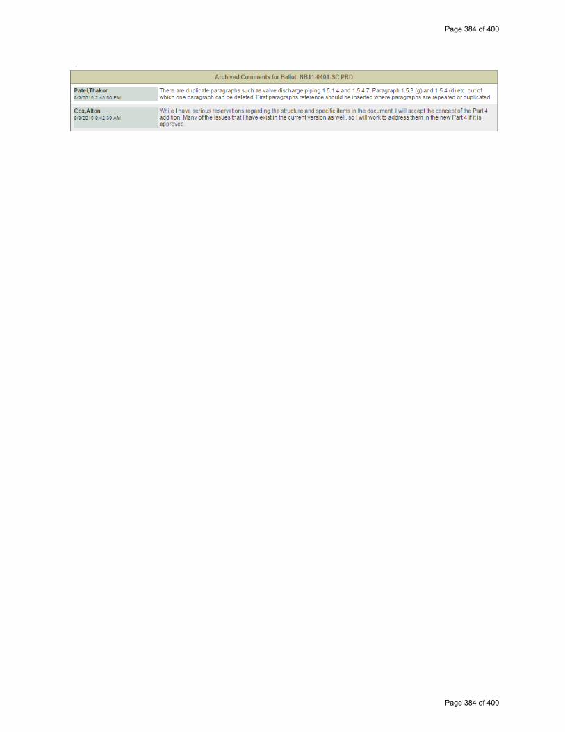
Page 384 of 400
Page 384 of 400

NB11‐1401 – 12/3/2015 – SC R/A Comments
Brian Boseo ‐ Should the following also be included in Part 4? 5.7.5 b) will have a change. 5.13.6 NVR Definitions "VR" Certificate Holder
James Pillow ‐ I approve, but have a question. Is it intended to move the Form NVR-1 to Part 4? In the proposal reference to the NVR-1 has been deleted in certain places but the instructions for completing the form have not.
Page 385 of 400
Page 385 of 400
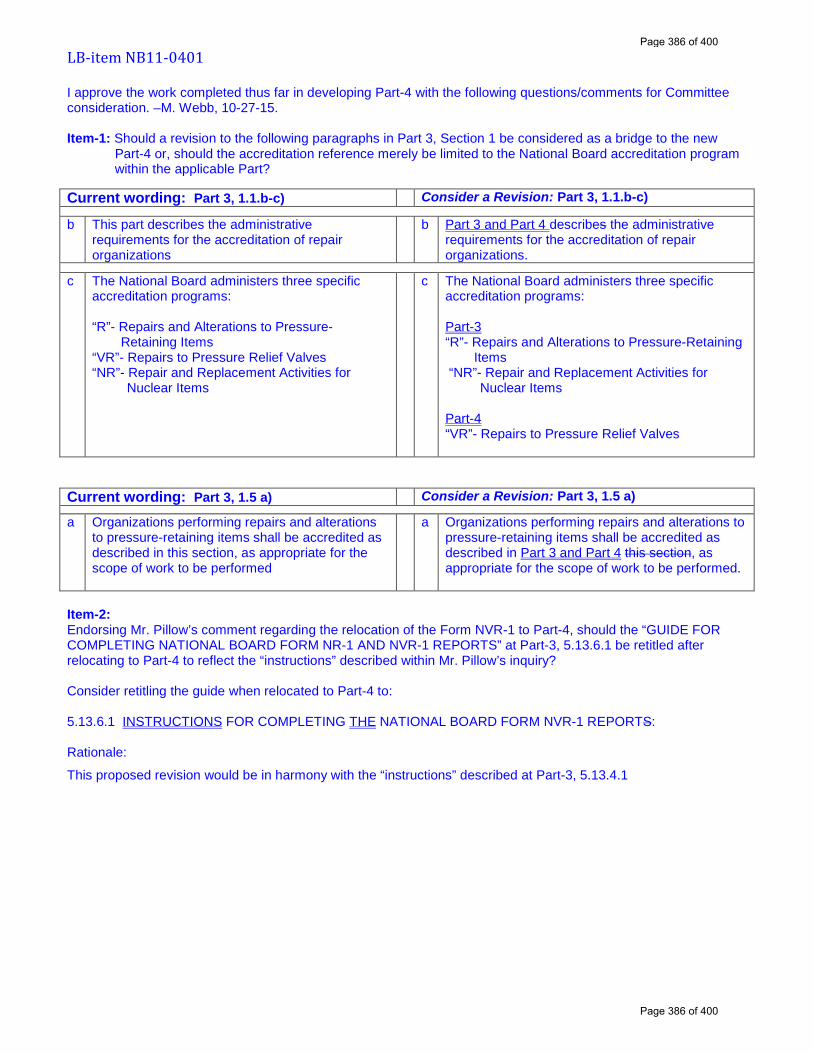
LB-item NB11-0401 I approve the work completed thus far in developing Part-4 with the following questions/comments for Committee consideration. –M. Webb, 10-27-15. Item-1: Should a revision to the following paragraphs in Part 3, Section 1 be considered as a bridge to the new
Part-4 or, should the accreditation reference merely be limited to the National Board accreditation program within the applicable Part?
Current wording: Part 3, 1.1.b-c) Consider a Revision: Part 3, 1.1.b-c)
b This part describes the administrative requirements for the accreditation of repair organizations
b Part 3 and Part 4 describes the administrative requirements for the accreditation of repair organizations.
c The National Board administers three specific accreditation programs: “R”- Repairs and Alterations to Pressure-
Retaining Items “VR”- Repairs to Pressure Relief Valves “NR”- Repair and Replacement Activities for
Nuclear Items
c The National Board administers three specific accreditation programs: Part-3 “R”- Repairs and Alterations to Pressure-Retaining
Items “NR”- Repair and Replacement Activities for
Nuclear Items Part-4 “VR”- Repairs to Pressure Relief Valves
Current wording: Part 3, 1.5 a) Consider a Revision: Part 3, 1.5 a)
a Organizations performing repairs and alterations to pressure-retaining items shall be accredited as described in this section, as appropriate for the scope of work to be performed
a Organizations performing repairs and alterations to pressure-retaining items shall be accredited as described in Part 3 and Part 4 this section, as appropriate for the scope of work to be performed.
Item-2: Endorsing Mr. Pillow’s comment regarding the relocation of the Form NVR-1 to Part-4, should the “GUIDE FOR COMPLETING NATIONAL BOARD FORM NR-1 AND NVR-1 REPORTS” at Part-3, 5.13.6.1 be retitled after relocating to Part-4 to reflect the “instructions” described within Mr. Pillow’s inquiry? Consider retitling the guide when relocated to Part-4 to: 5.13.6.1 INSTRUCTIONS FOR COMPLETING THE NATIONAL BOARD FORM NVR-1 REPORTS: Rationale:
This proposed revision would be in harmony with the “instructions” described at Part-3, 5.13.4.1
Page 386 of 400
Page 386 of 400

Action Item Request Form
8.3 CODE REVISIONS OR ADDITIONS
Request for Code revisions or additions shall provide the following:
a) Proposed Revisions or Additions
For revisions, identify the rules of the Code that require revision and submit a copy of the appropriate
rules as they appear in the Code, marked up with the proposed revision. For additions, provide the
recommended wording referenced to the existing Code rules.
Existing Text:
b) Statement of Need
Provide a brief explanation of the need for the revision or addition.
c) The opening or connection between the boiler and the safety or safety relief valve shall have at least the
area of the valve inlet and the inlet pipe to the pressure relief valve shall be no longer than the face to face
dimension of the corresponding tee fitting of the same diameter and pressure class. When a discharge pipe is
used, the cross‐sectional area shall not be less than the full area of the valve outlet or of the total of the areas
of the valve outlets discharging there into and shall be as short and straight as possible and arranged to avoid
undue stresses on the valve or valves.
Although the existing text is similar to ASME Section I PG‐71.2, the face‐to‐face linear dimension of the
tee is not well defined.
PG‐71.2 The pressure relief valve or valves shall be connected to the boiler independent of any other connection, and attached as close as possible to the boiler or the normal steam flow path, without any unnecessary intervening pipe or fitting. Such intervening pipe or fitting shall be not longer than the face‐to‐face dimension of the corresponding tee fitting of the same diameter and pressure under the applicable ASME Standard listed in PG‐42 and shall also comply with PG‐8 and PG‐39. Every pressure relief valve shall be connected so as to stand in an upright position, with spindle vertical. On high‐temperature water boilers of the watertube forced‐circulation type, the valve shall be located at the boiler outlet.
NB15‐0103 Page 387 of 400
Page 387 of 400
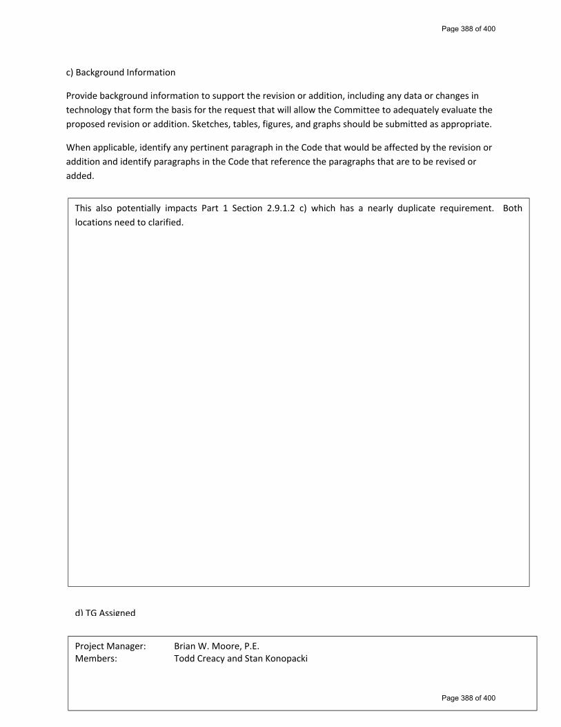
c) Background Information
Provide background information to support the revision or addition, including any data or changes in
technology that form the basis for the request that will allow the Committee to adequately evaluate the
proposed revision or addition. Sketches, tables, figures, and graphs should be submitted as appropriate.
When applicable, identify any pertinent paragraph in the Code that would be affected by the revision or
addition and identify paragraphs in the Code that reference the paragraphs that are to be revised or
added.
This also potentially impacts Part 1 Section 2.9.1.2 c) which has a nearly duplicate requirement. Both
locations need to clarified.
d) TG Assigned
Project Manager: Brian W. Moore, P.E. Members: Todd Creacy and Stan Konopacki
Page 388 of 400
Page 388 of 400
Rupture Pin Technology
Rupture Pin Valve
Installation, Operation and Maintenance Instructions
Model CASME Angle Body Valves
You have purchased the latest technology in pressure relief devices. The Rupture
Pin Valve has been developed from years of research and development in a quest to solve
many of the shortcomings of other pressure relief devices. These instructions are
provided to guide qualified Maintenance Personnel in the Installation, Operation and
Maintenance of Rupture Pin Valves. It is not all-inclusive and should be used as a guide
with recognized safe valve installation, operation and maintenance practices.
Unpacking - Rupture Pin Valves are shipped in boxes, crates or on pallets. Valves
should be carefullyunboxed/uncrated or unstrapped and all packing material removed
from valve. Documentation for the valve(s) is enclosed with the valve in an envelope.
This pack contains Valve Test Certification(s), Certified Drawings and these instructions.
Information contained in this pack must be stored in a safe place for future reference. The
certified drawings indicate recommended spare parts for one year’s operation. Pin re-
ordering data can be found on the Test Certificate or the Valve’s Data tag, attached to
each valve (please provide valve Serial Number and Pin Code).
Care should be taken to avoid handling the valve by the Pin Cage. The Pin Cage
is carefully aligned and adjusted when the valve is certified; this alignment must be
maintained for proper operation. While the Pin Cage is quite rugged, careful handling
will avoid any problems in operation. Improperly aligned Pin Cages always result in
lower set point.
Installation - Rupture Pin Valves are installed just as other relief devices. All flanged
valves require the use of proper gaskets or sealing aids. Flange faces should be wiped
clean with a suitable solvent prior to installation. Threaded valves should be installed
with Teflon tape or other suitable thread sealant. Flange connections should be bolted
with only approved bolting materials, with proper torguing practices. Threaded valves
should be properly tightened before operation. Typically, Model CASME valves are
installed with the inlet down/pin up vertical. Any other installation must be specified at
time of testing at RPT factory. Shipping pin shall be replaced with the proper tagged pin
before placing valve into service in order to prevent mechanical failures or safety issues.
Operation - Rupture Pin Valves operate on the simple principle of Euler’s Law. The
Pin acts as the sensor and the actuator. As the pressure acts upon the valve’s piston
surface(s), an axial force is applied to the Pin. As the pressure approaches the set point of
the valve, the pin may bow under the load. If the line pressure is removed, the Pin will
return to its original shape. No permanent deflection is created because the Pin has not
Page 389 of 400
Page 389 of 400
passed its elastic limit. However, if the pressure is increased to the set point, the load will
on the pin will become sufficient enough to cause the pin to rupture, allowing the valve to
open very quickly.
To reset the valve, the pressure must be reduced, preferably removed, so that the
piston may be reseated and a new pin installed. Excessive pressure will not allow the
Piston to be reseated and may be unsafe.
Reseating the Piston Assembly is done by removing the bent pin from the valve
and pushing the assembly back on seat. Do these by first removing the holding nut (see
drawing) and removing the bent pin (it may be necessary to wiggle the pin slightly since
the pin is held in a very precision bore). Now the Piston Assembly may be pushed back
on seat (into the valve). A steady push is desired over a quick push, to avoid damaging
the piston seal o-ring. If the valve does not go on seat easily or leaks after resealing, then
piston seal damage may have occurred. Refer to the Maintenance section for specific
instructions on piston seal o-ring replacement.
Once the Piston Assembly has been reseated, a new pin may be placed into the
piston’s tapered holding nut. The holding nut does not need to be real tight. Slightly snug
the holding nut with a wrench. It just needs to be tight enough to overcome vibrations,
which would cause it to fall out. The valve is now ready for operation.
A word of caution; the Piston Stem of the valve must be protected from nicks and
scratches when it is exposed. Bushing seals will be damaged and possibly leaks may
develop if the stem is damaged. It is also important to avoid the Pin Cage with all parts of
a person’s body, wrenches and tools while the valve is in service. An overpressure
condition may occur at any moment and severe damage to one’s self or the valve could
result if the pin were to rupture.
Maintenance - Rupture Pin Valves require very little maintenance. Typically, the Model
CASME has up to seven (7) O-rings; one (1) piston seal, two (2) bonnet seals, two (2)
stem and bushing seals (depending upon Model & Size). All seals may be replaced by
removing the Bonnet Assembly. It is not necessary or recommended that the Pin Cage be
disassembled. Removal from the vessel is the choice of the Maintenance Personnel, based
on the material flowing through the valve and personal judgment. Removal is not
required to service the Model CASME Valve, but is recommended for complete thorough
inspection (the inlet seat area is difficult to inspect without looking into the inlet port).
To replace any seals, the Bonnet Assembly must be removed (all pressure should
be removed from the valve and blocking valves closed if the valve is left in place. The
Bonnet Assembly is removed, as a unit, by removing all of the Bonnet Bolts. For
information on disassembly of the Pin Cage, see next section of these instructions.
With the Bonnet Bolts removed, the Bonnet Assembly may be removed. The
Bonnet Assembly slides out of the body. Pry slots are provided on some Models while
others may have lifting lugs. Those without are generally small enough to handle without
these aids.
With the Bonnet Assembly out of the valve, all seals can be reached for
inspection and replacement. Start by removing the Piston Assembly by pulling it down
and out of the Gland Bushing (if equipped). The Gland bushing can be removed by
removing the snap ring, retaining bolts, or retaining ring. This is all that is required to
service all seals.
Page 390 of 400
Page 390 of 400
Inspect all o-ring, grooves and matching sealing surfaces for foreign material,
nicks and scratches. Remove any foreign material by a suitable means. Avoid creating
any damage to the sealing surfaces while removing the foreign material. Any nicks and
scratches may be polishes out with emery cloth (220 grit or finer). Castor oil is
recommended as an o-ring lubricant when re-assembling. Commercial o-ring lubricants
tend to become stick over a long length of time where as castor oil will not.
The Piston Seat area should be inspected for any foreign material or damage.
Inspection of the Piston O-ring Groove is also necessary for damage or foreign material.
The same procedure for the bonnet and gland bushing applies.
When all seals and sealing surfaces are inspected, installed and lubricated with
castor oil, assembly is opposite of disassembly.
Disassembly of Pin Cage - It is not recommended that more than one valve be
disassembled at a time to avoid mixing of spacers and posts. Spacers and post are custom
machined to match each valve as to its specific set point. If several valves are to be
disassembled at one time, it is recommended that the parts be identified as to their origin
before disassembly has begun. Mixing of post and spacers usually result in inaccurate set
points (usually lower).
Begin by removing the Holding Nut and removing the Pin. Remove the hex nuts
located on the top of the Top Plate. This will allow for the Top Plate to be removed. The
spacers can then be slid off the post. The post is threaded into the bonnet. They may be
difficult to remove and a lubricant such as WD-40 may be applied to assist in removal.
Assembly is opposite of disassembly. Warning – It is important that the Pin Cage
assembly be in alignment with the bonnet. Tighten bolts in a “star” pattern to keep equal
torque on all post. Once cage is reassembled, an installed pin should spin freely between
to piston insert and the holding nut.
A word of caution; many pinch points are present when disassembling/assembling
a Model CASME. Care should be taken to avoid putting one’s personal position on
danger. All the parts have been carefully machined and should not require excessive force
to take apart. If parts are difficult to remove, inspect other parts of the valve for
interferences.
Unexpected Problems - Should you encounter any unexpected problems, need
assistance or require Replacement Pins, feel free to call Rupture Pin Technology for help.
They can be reached at (405)789-1884 from 8:00 am – 4:30 pm (CST). Please have the
Valve Serial Number (found on valve tag and Test Certificate) ready when you call.
Rev D 02/07/00 EL
Page 391 of 400
Page 391 of 400
This document provides general guidelines for the critical inspection points and repair process during the repair of a buckling pin relief valve covered under ASME Section VIII Div. 1
Inspection points during the repair
Ensure the top seal is not tampered or removed Inspect for any visible leakage or damage Disassemble the valve by removing bonnet bolts Check all the elastomers for any permanent deformation wear and tear Check for any physical damage to all valve components Check for any debris / deposits from the process and make sure all the parts are clean before further
inspection Inspect all the critical dimensions – Seat diameter, Piston diameter, Stem diameter Check the seat for out of roundness Check the surface finish on sealing surfaces
Repair process
Install new elastomers if required. Make sure to use appropriate lubricant while installing new seals Clean-up any damaged surfaces on valve components If the components are beyond clean-up or repair, install new components Assemble the valve using manufacturer’s IOM Once the assembly is complete, ensure the lift of the valve is per specifications Perform the set pressure test by testing at least 3 pins to ensure correct set pressure is acquired within the
required tolerance Perform hydrotest at a min 1.5 times MAWP to ensure joint integrity Perform back pressure test at a min 30 psig air Install a new name plate if required and ensure the valve is sealed before shipping
Prepared by: Alok Dange Buckling Pin valve repair Date: 6‐5‐2015
Page 392 of 400
Page 392 of 400
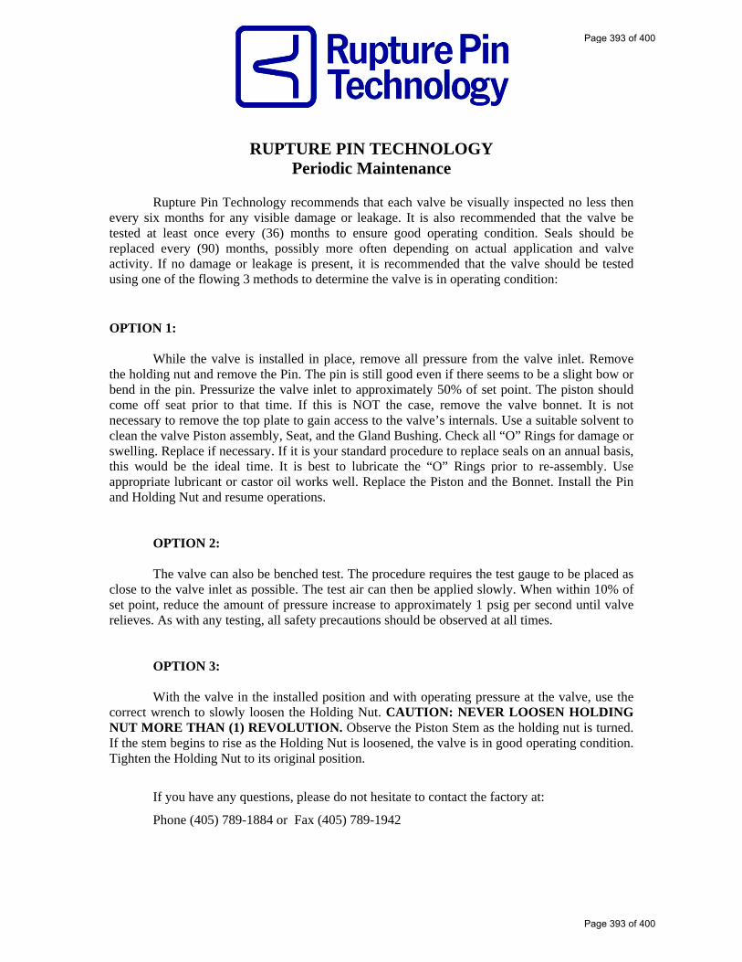
RUPTURE PIN TECHNOLOGY Periodic Maintenance
Rupture Pin Technology recommends that each valve be visually inspected no less then
every six months for any visible damage or leakage. It is also recommended that the valve be tested at least once every (36) months to ensure good operating condition. Seals should be replaced every (90) months, possibly more often depending on actual application and valve activity. If no damage or leakage is present, it is recommended that the valve should be tested using one of the flowing 3 methods to determine the valve is in operating condition: OPTION 1:
While the valve is installed in place, remove all pressure from the valve inlet. Remove the holding nut and remove the Pin. The pin is still good even if there seems to be a slight bow or bend in the pin. Pressurize the valve inlet to approximately 50% of set point. The piston should come off seat prior to that time. If this is NOT the case, remove the valve bonnet. It is not necessary to remove the top plate to gain access to the valve’s internals. Use a suitable solvent to clean the valve Piston assembly, Seat, and the Gland Bushing. Check all “O” Rings for damage or swelling. Replace if necessary. If it is your standard procedure to replace seals on an annual basis, this would be the ideal time. It is best to lubricate the “O” Rings prior to re-assembly. Use appropriate lubricant or castor oil works well. Replace the Piston and the Bonnet. Install the Pin and Holding Nut and resume operations.
OPTION 2: The valve can also be benched test. The procedure requires the test gauge to be placed as
close to the valve inlet as possible. The test air can then be applied slowly. When within 10% of set point, reduce the amount of pressure increase to approximately 1 psig per second until valve relieves. As with any testing, all safety precautions should be observed at all times.
OPTION 3: With the valve in the installed position and with operating pressure at the valve, use the
correct wrench to slowly loosen the Holding Nut. CAUTION: NEVER LOOSEN HOLDING NUT MORE THAN (1) REVOLUTION. Observe the Piston Stem as the holding nut is turned. If the stem begins to rise as the Holding Nut is loosened, the valve is in good operating condition. Tighten the Holding Nut to its original position.
If you have any questions, please do not hesitate to contact the factory at:
Phone (405) 789-1884 or Fax (405) 789-1942
Page 393 of 400
Page 393 of 400

NB15‐1001; NB15‐1002; NB15‐1003; NB15‐1004
Include the following text in the Introduction under the heading “Stamping”
ASME Code “Stamping” referenced throughout the NBIC includes the ASME Boiler and Pressure Vessel
Code Symbol Stamps used for conformity assessment prior to the 2010 edition/2011 addendum and the
equivalent ASME Certification Mark with Designator required to meet the later editions of the ASME
Boiler and Pressure Vessel Code Sections. When other construction codes or standards are utilized for
repairs or alterations, stamping shall mean the identification symbol stamp required by that code or
standard to indicate conformity assessment.
Page 394 of 400
Page 394 of 400
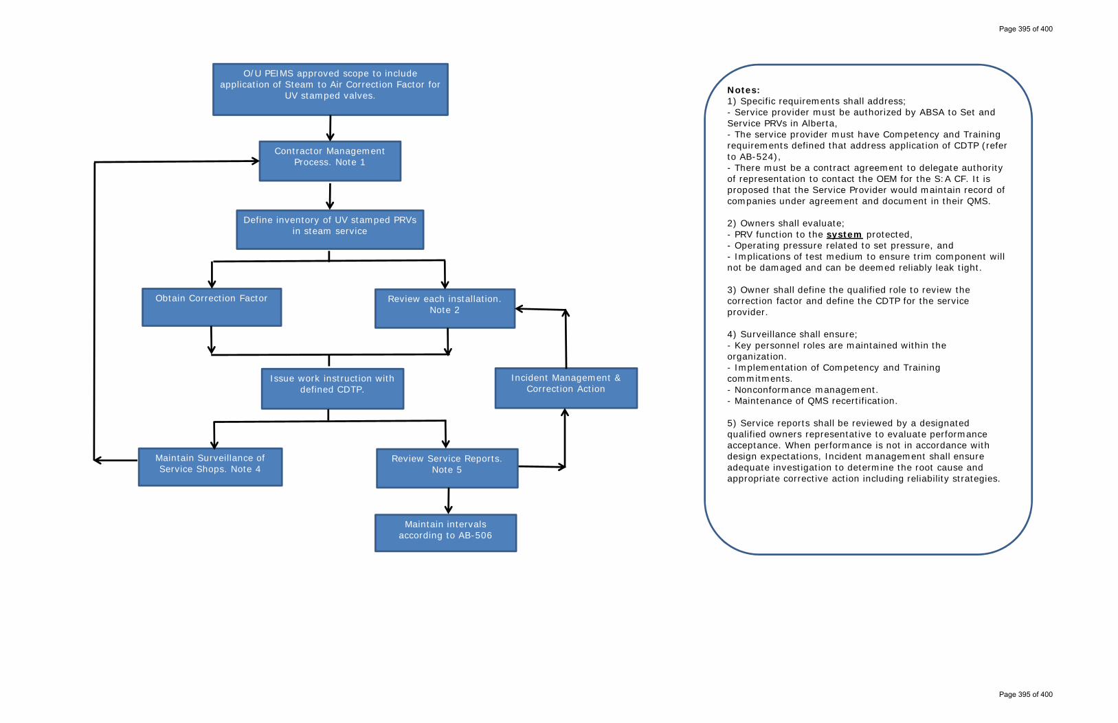
O/U PEIMS approved scope to include application of Steam to Air Correction Factor for
UV stamped valves.
Contractor Management Process. Note 1
Obtain Correction Factor Review each installation. Note 2
Define inventory of UV stamped PRVs in steam service
Issue work instruction with defined CDTP.
Maintain Surveillance of Service Shops. Note 4
Review Service Reports. Note 5
Maintain intervals according to AB-506
Incident Management & Correction Action
Notes:1) Specific requirements shall address; - Service provider must be authorized by ABSA to Set and Service PRVs in Alberta, - The service provider must have Competency and Training requirements defined that address application of CDTP (refer to AB-524), - There must be a contract agreement to delegate authority of representation to contact the OEM for the S:A CF. It is proposed that the Service Provider would maintain record of companies under agreement and document in their QMS.
2) Owners shall evaluate;- PRV function to the system protected,- Operating pressure related to set pressure, and- Implications of test medium to ensure trim component will not be damaged and can be deemed reliably leak tight.
3) Owner shall define the qualified role to review the correction factor and define the CDTP for the service provider.
4) Surveillance shall ensure;- Key personnel roles are maintained within the organization.- Implementation of Competency and Training commitments.- Nonconformance management.- Maintenance of QMS recertification.
5) Service reports shall be reviewed by a designated qualified owners representative to evaluate performance acceptance. When performance is not in accordance with design expectations, Incident management shall ensure adequate investigation to determine the root cause and appropriate corrective action including reliability strategies.
Page 395 of 400
Page 395 of 400
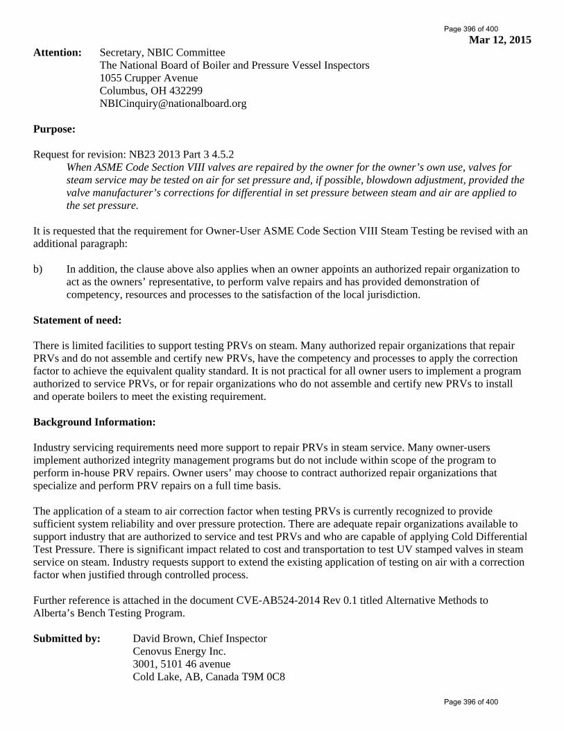
Mar 12, 2015 Attention: Secretary, NBIC Committee The National Board of Boiler and Pressure Vessel Inspectors 1055 Crupper Avenue Columbus, OH 432299 [email protected] Purpose: Request for revision: NB23 2013 Part 3 4.5.2
When ASME Code Section VIII valves are repaired by the owner for the owner’s own use, valves for steam service may be tested on air for set pressure and, if possible, blowdown adjustment, provided the valve manufacturer’s corrections for differential in set pressure between steam and air are applied to the set pressure.
It is requested that the requirement for Owner-User ASME Code Section VIII Steam Testing be revised with an additional paragraph: b) In addition, the clause above also applies when an owner appoints an authorized repair organization to
act as the owners’ representative, to perform valve repairs and has provided demonstration of competency, resources and processes to the satisfaction of the local jurisdiction.
Statement of need: There is limited facilities to support testing PRVs on steam. Many authorized repair organizations that repair PRVs and do not assemble and certify new PRVs, have the competency and processes to apply the correction factor to achieve the equivalent quality standard. It is not practical for all owner users to implement a program authorized to service PRVs, or for repair organizations who do not assemble and certify new PRVs to install and operate boilers to meet the existing requirement. Background Information: Industry servicing requirements need more support to repair PRVs in steam service. Many owner-users implement authorized integrity management programs but do not include within scope of the program to perform in-house PRV repairs. Owner users’ may choose to contract authorized repair organizations that specialize and perform PRV repairs on a full time basis. The application of a steam to air correction factor when testing PRVs is currently recognized to provide sufficient system reliability and over pressure protection. There are adequate repair organizations available to support industry that are authorized to service and test PRVs and who are capable of applying Cold Differential Test Pressure. There is significant impact related to cost and transportation to test UV stamped valves in steam service on steam. Industry requests support to extend the existing application of testing on air with a correction factor when justified through controlled process. Further reference is attached in the document CVE-AB524-2014 Rev 0.1 titled Alternative Methods to Alberta’s Bench Testing Program. Submitted by: David Brown, Chief Inspector Cenovus Energy Inc. 3001, 5101 46 avenue Cold Lake, AB, Canada T9M 0C8
Page 396 of 400
Page 396 of 400

Page 1 of 3 Document: CVE-AB524-2014 Rev. 0.1 Issued to Industry for Review Dec. 11, 2014
WHITE PAPER
Alternative Methods to Alberta’s Bench Testing Program
Introduction In early 2013, ABSA the pressure equipment safety authority issued the Pressure Relief Devices Requirements AB-524 document. This document applies to the manufacture, assembly, selection and sizing, inspections, repairs, servicing, setting & sealing and installation of Pressure Relief Devices in Alberta. The requirements document became mandatory January 1, 2014. This proposal is to focus attention on section 3.3 Scope of Alberta’s Bench Test program. Industry has expressed concerns the requirements outlined for steam service pressure relief valves will introduce significant economic impact. This paper is intended to prompt the Regulator to support industry to provide practical alternative methods to achieve an equal or better standard of safety and reliability. Background National Board Inspection and ASME Codes specify requirement for testing Pressure Relief Valves (PRVs). The purpose is to ensure that PRVs are maintained to be reliable upon demand in accordance to strict design. The recognized best practice is to test the PRVs on the medium most comparable to the actual service fluid. In the case of UV stamped PRVs in steam service, Codes accept that PRVs can be tested on steam or air if a manufacturers steam to air correction factor is applied. PRVs are recognized to be significant to process safety and are often referred to as the last line of defense. Many organizations have mature owner-user integrity management systems that address all elements through-out the pressure equipment life cycle. Although PRVs are the last line of defense, they are not the only line of defense. Industry has been guilty of not complying to the specific code requirements of testing UV steam service PRVs. With the introduction of AB-524 and the elevated awareness of requirements many organizations have been significantly impacted. In many cases it is not practical, and sometimes not possible to comply with methods to a) test the PRVs on production equipment, b) access a service shop capable of setting on steam, or c) performing online lift assist testing.
a) Operating installations may not have the required instrumentation and controls to safely manage elevating the process pressure to the design set pressure. In some systems process fluids have contaminants that may harm the sealing surfaces if lifted online and result in uncontrolled loss of process fluids and production outage.
b) There are limited number of qualified shops in Alberta that can set steam PRVs. The shop boilers are relatively small and have limited capacity to set PRVs with high set pressures and often will require a supplemented lift assist at the shop. The restricted access to qualified shops can require extensive transportation to and from remote operating facilities. With high demand on the limited shops, PRV
Page 397 of 400
Page 397 of 400

Page 2 of 3 Document: CVE-AB524-2014 Rev. 0.1 Issued to Industry for Review Dec. 11, 2014
servicing is at a premium cost and often requires extended time to complete servicing. Do to the extended service time, many valves have to have redundant duplicates purchased to minimize extended outages and lost production revenue.
c) Lift assist testing requires specific design conditions to be applied successfully. There must be access to online pressure monitoring near the PRV location, the operating condition must be static and close to set pressure, and there must be adequate clearance to install the lift device on the PRV stem. In some cases the installation may not have been designed to accommodate all of the requirements.
National Board Inspection Code has limited only Owner-user’s with authorization to repair PRVs for the owner’s own use to be allowed to test UV steam service PRVs on air and apply the manufacturers steam to air correction factor. It is understood that the intent of this restriction is to prevent the misuse of the steam to air correction factor due to lack of adequate processes and management. Currently, Owners that include repair of PRVs in their Quality Management System (QMS) may test UV steam service PRVs on air, apply the manufacturers procedures and the steam to air correction factor. Owner-users who do not currently, may choose to expand the scope of their QMS to include repairing their own PRVs and become authorized to test UV steam service PRVs on air. Pending on the scale of the operation, it is often not practical to develop, implement and sustain all the resources to manage PRV servicing. Additional environmental issues related to remote locations, limited workforce availability and lack of a trades program for valve servicing increases the complication. With small communities supporting remote locations and the shortage in the labor pool it is difficult to attract and retain personnel that respect and honor the craft with professional pride. With the lack of a trades program, the service provider becomes primarily accountable for developing the competency of PRV repair technicians. Problem Without allowing UV steam service PRVs to be tested on air at local authorized service shops, extended complications and expense is occurred by Owners and service providers. High Level Solution Allow Owner’s with proven performance, appropriate organization, documented work processes and designated competent resources to test UV steam service PRVs on air and manage the application of steam to air correction factors under their QMS Certificate of Authorization Permit (CAP) through partnership with existing authorized service providers. Solution Details Through means of an Information Bulletin provide interpretation to clarify that Alberta QMS programs can address partnership between authorized service shops and authorized Owner-users to test UV steam service PRVs on air and operate with an equal or greater level of safety. Future revision of AB-524 can include reference and application to this interpretation.
Page 398 of 400
Page 398 of 400

Page 3 of 3 Document: CVE-AB524-2014 Rev. 0.1 Issued to Industry for Review Dec. 11, 2014
The Owners quality management system would have to address requirements for:
a) Defining criteria to justify that testing the PRV on air with a steam to air correction factor will provide the required confidence factor for the system criticality.
b) Qualifying service providers to repair PRVs. c) Written contract with service provider to act as a designate on behalf of the owner
to approach the PRV manufacturer for the steam to air correction factors and application procedures. The service provider will maintain their QMS to reflect that they are acting as a designate to provide related service for administration and audit purpose.
d) Ensuring service provider maintains training, competency and procedures related to testing UV steam service PRVs with air.
e) Incident investigation for events when a PRV lifts and or a system is exposed to over pressure, including disposition of appropriate corrective and preventative actions.
f) Management of Change g) Process revalidation at defined intervals. h) Commitment to monitor program effectiveness with specific matrix assigned for
PRV performance.
Benefits Existing PRV service companies can remain competitive in their respective communities without having to install boilers, purchase lift assist devices and qualify technicians to provide related service. By allowing Owners to partner with the existing service companies to utilize their professionals, it avoids competition to attract and retain current senior technicians. This has been an ongoing issue for contract inspection companies who develop and train inspectors only to lose them to Owner companies. Owners will be able to remain competitive and manage costs associated with maintaining UV steam service PRVs without paying premiums to exclusive shops, paying for extensive transportation costs or having to purchase duplicates valves. Owners that commit to the integrity management requirements will have more extensive layers of mitigation for process safety and not be relying on the PRVs reactively. Summary / Conclusion Codes and Regulations have been adopted and implemented to promote safe and reliable operation. Opportunity exists to challenge current practices to evaluate alternative approaches to maintain the standards of safety and reliability while empowering Owner’s to be effective and efficient in competitive markets. Regulators that partner with industry to develop alternative methods promote responsible growth and sustainability.
Page 399 of 400
Page 399 of 400
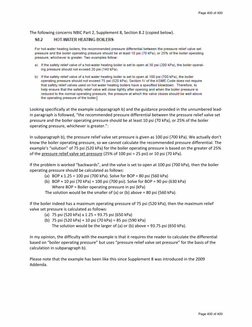
The following concerns NBIC Part 2, Supplement 8, Section 8.2 (copied below).
Looking specifically at the example subparagraph b) and the guidance provided in the unnumbered lead‐in paragraph is followed, “the recommended pressure differential between the pressure relief valve set pressure and the boiler operating pressure should be at least 10 psi (70 kPa), or 25% of the boiler operating pressure, whichever is greater.”: In subparagraph b), the pressure relief valve set pressure is given as 100 psi (700 kPa). We actually don’t know the boiler operating pressure, so we cannot calculate the recommended pressure differential. The example’s “solution” of 75 psi (520 kPa) for the boiler operating pressure is based on the greater of 25% of the pressure relief valve set pressure (25% of 100 psi = 25 psi) or 10 psi (70 kPa). If the problem is worked “backwards”, and the valve is set to open at 100 psi (700 kPa), then the boiler operating pressure should be calculated as follows:
(a) BOP x 1.25 = 100 psi (700 kPa). Solve for BOP = 80 psi (560 kPa) (b) BOP + 10 psi (70 kPa) = 100 psi (700 psi). Solve for BOP = 90 psi (630 kPa)
Where BOP = Boiler operating pressure in psi (kPa) The solution would be the smaller of (a) or (b) above = 80 psi (560 kPa). If the boiler indeed has a maximum operating pressure of 75 psi (520 kPa), then the maximum relief valve set pressure is calculated as follows:
(a) 75 psi (520 kPa) x 1.25 = 93.75 psi (650 kPa) (b) 75 psi (520 kPa) + 10 psi (70 kPa) = 85 psi (590 kPa)
The solution would be the larger of (a) or (b) above = 93.75 psi (650 kPa).
In my opinion, the difficulty with the example is that it requires the reader to calculate the differential based on “boiler operating pressure” but uses “pressure relief valve set pressure” for the basis of the calculation in subparagraph b). Please note that the example has been like this since Supplement 8 was introduced in the 2009 Addenda.
Page 400 of 400
Page 400 of 400