page 1 of 41 - national fire protection association · 12-fr_15.docx annex material submitter...
TRANSCRIPT

First Revision No. 14-NFPA 12-2016 [ Section No. 1.2.2 ]
1.2.2 Equivalency.
Nothing in this standard is intended to restrict new technologies or alternative arrangements, provided thelevel of safety prescribed by the standard is not lowered prevent the use of systems, methods, or devicesof equivalent or superior quality, strength, fire resistance, effectiveness, durability, and safety over thoseprescribed by this standard .
1.2.2.1
Technical documentation shall be submitted to the authority having jurisdiction to demonstrateequivalency.
1.2.2.2
The system, method, or device shall be approved for the intended purpose by the authority havingjurisdiction.
Submitter Information Verification
Submitter Full Name: Barry Chase
Organization: [ Not Specified ]
Street Address:
City:
State:
Zip:
Submittal Date: Fri Mar 18 10:35:11 EDT 2016
Committee Statement
Committee Statement: The equivalency statement has been revised to use the standard language.
Response Message:
National Fire Protection Association Report http://submittals.nfpa.org/TerraViewWeb/ContentFetcher?commentPara...
1 of 39 5/2/2016 7:19 AM
Page 1 of 41
First Revision No. 15-NFPA 12-2016 [ Sections 1.3.4, 1.3.5 ]
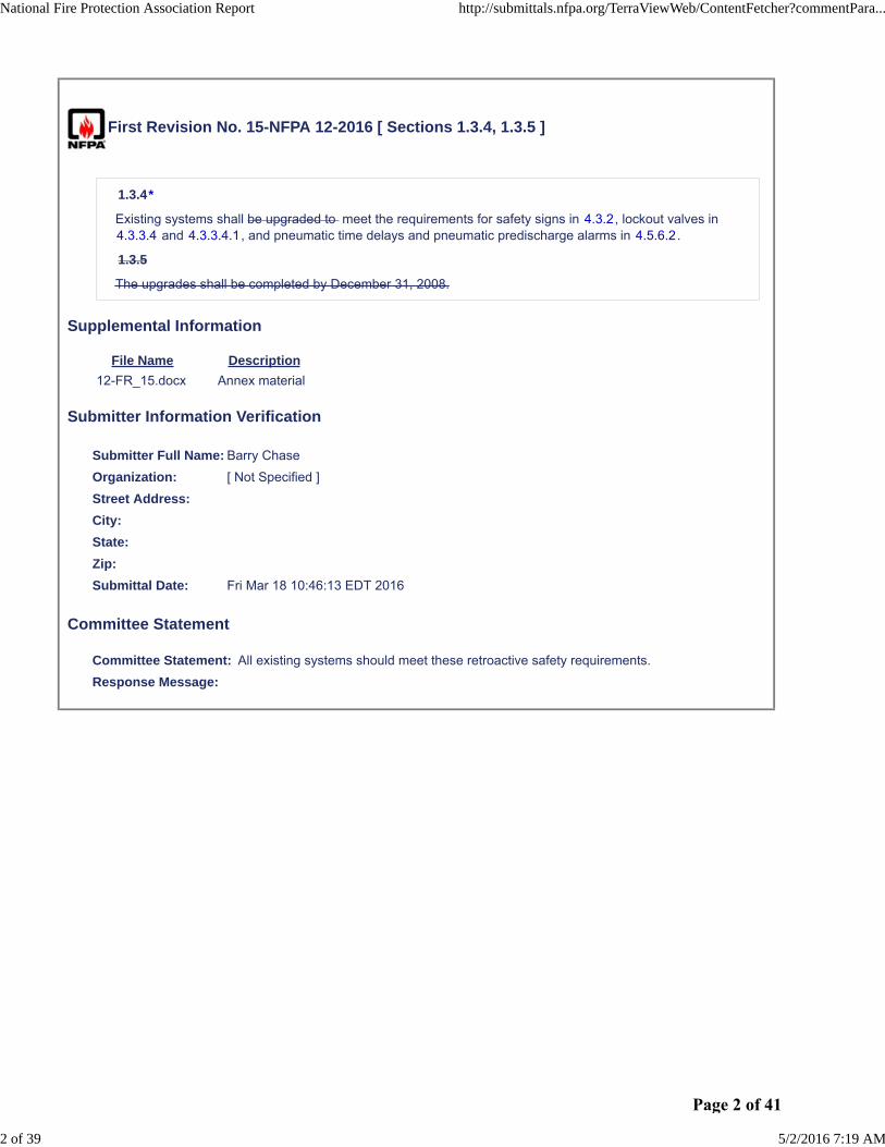
1.3.4*
Existing systems shall be upgraded to meet the requirements for safety signs in 4.3.2, lockout valves in4.3.3.4 and 4.3.3.4.1, and pneumatic time delays and pneumatic predischarge alarms in 4.5.6.2.
1.3.5
The upgrades shall be completed by December 31, 2008.
Supplemental Information
File Name Description
12-FR_15.docx Annex material
Submitter Information Verification
Submitter Full Name: Barry Chase
Organization: [ Not Specified ]
Street Address:
City:
State:
Zip:
Submittal Date: Fri Mar 18 10:46:13 EDT 2016
Committee Statement
Committee Statement: All existing systems should meet these retroactive safety requirements.
Response Message:
National Fire Protection Association Report http://submittals.nfpa.org/TerraViewWeb/ContentFetcher?commentPara...
2 of 39 5/2/2016 7:19 AM
Page 2 of 41
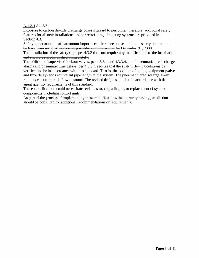
A.1.3.4 A.1.3.5 Exposure to carbon dioxide discharge poses a hazard to personnel; therefore, additional safety features for all new installations and for retrofitting of existing systems are provided in Section 4.3. Safety to personnel is of paramount importance; therefore, these additional safety features should be have been installed as soon as possible but no later than by December 31, 2008. The installation of the safety signs per 4.3.2 does not require any modifications to the installation and should be accomplished immediately. The addition of supervised lockout valves, per 4.3.3.4 and 4.3.3.4.1, and pneumatic predischarge alarms and pneumatic time delays, per 4.5.5.7, require that the system flow calculations be verified and be in accordance with this standard. That is, the addition of piping equipment (valve and time delay) adds equivalent pipe length to the system. The pneumatic predischarge alarm requires carbon dioxide flow to sound. The revised design should be in accordance with the agent quantity requirements of this standard. These modifications could necessitate revisions to, upgrading of, or replacement of system components, including control units. As part of the process of implementing these modifications, the authority having jurisdiction should be consulted for additional recommendations or requirements.
Page 3 of 41

First Revision No. 1-NFPA 12-2016 [ Chapter 2 ]
Chapter 2 Referenced Publications
2.1 General.
The documents or portions thereof listed in this chapter are referenced within this standard and shall beconsidered part of the requirements of this document.
2.2 NFPA Publications.
National Fire Protection Association, 1 Batterymarch Park, Quincy, MA 02169-7471.
NFPA 4, Standard for Integrated Fire Protection and Life Safety System Testing, 2018 edition.
NFPA 70®, National Electrical Code®, 2014 2017 edition.
NFPA 72®, National Fire Alarm and Signaling Code, 2013 2016 edition.
2.3 Other Publications.
2.3.1 ANSI Publications.
American National Standards Institute, Inc., 25 West 43rd Street, 4th Floor, New York, NY 10036.
ANSI/IEEE C2, National Electrical Safety Code , 2012.
ANSI Z535.2 , Standard for Environmental and Facility Safety Signs, 2011.
2.3.2 API Publications.
American Petroleum Institute, 1220 L Street, NW, Washington, DC 20005-4070.
API-ASME Code for Unfired Pressure Vessels for Petroleum Liquids and Gases, Pre–July 1, 1961.
2.3.3 ASME Publications.
American Society of Mechanical Engineers, Two Park Avenue, New York, NY 10016-5990.
ASME B31.1, Power Piping Code, 2012 2014 .
2.3.4 ASTM Publications.
ASTM International, 100 Barr Harbor Drive, P.O. Box C700, West Conshohocken, PA 19428-2959.
ASTM A53/A53M , Standard Specification for Pipe, Steel, Black and Hot-Dipped, Zinc-Coated, Weldedand Seamless, 2012.
ASTM A106/A106M , Standard Specification for Seamless Carbon Steel Pipe for High-TemperatureService, 2011 2015 .
ASTM A120, Specification for Pipe, Steel, Black and Hot-Dipped Zinc-Coated (Galvanized) Welded andSeamless for Ordinary Uses, 1984 (withdrawn 1987).
ASTM A182/A182M , Standard Specification for Forged or Rolled Alloy and Stainless Steel Pipe Flanges,Forged Fittings, and Valves and Parts for High-Temperature Service, 2012 2015 .
2.3.5 CGA Publications.
Compressed Gas Association, 14501 George Carter Way, Suite 103, Chantilly, VA 20151-2923.
CGA G6.2 G-6.2 , Commodity Specification for Carbon Dioxide, 2011.
2.3.6 CSA Group Publications.
Canadian Standards Association, 5060 Spectrum Way, Mississauga, ON, L4W 5N6 178 Rexdale Blvd.,Toronto, ON M9W 1R3 , Canada.
CSA C22.1, Canadian Electrical Code, 2012.
National Fire Protection Association Report http://submittals.nfpa.org/TerraViewWeb/ContentFetcher?commentPara...
3 of 39 5/2/2016 7:19 AM
Page 4 of 41

2.3.7 IEEE Publications.
IEEE Standards Association, 3 Park Avenue, 17th Floor, New York, NY 10016-5997.
IEEE C2, National Electrical Safety Code , 2012.
2.3.8 U.S. Government Publications.
U.S. Government Printing Publishing Office, 732 North Capitol Street, NW, Washington, DC20402 20401-0001 .
Title 46, Code of Federal Regulations, Part 58.20.
Title 46, Code of Federal Regulations, Part 72.
Title 49, Code of Federal Regulations, Parts 171–190 (Department of Transportation).
Coward, H. F., and G. W. Jones, Limits of Flammability of Gases and Vapors, U.S. Bureau of MinesBulletin 503,1952.
Zabetakis, Michael G., Flammability Characteristics of Combustible Gases and Vapors, U.S. Bureau ofMines Bulletin 627, 1965.
2.3.9 Other Publications.
Merriam-Webster’s Collegiate Dictionary, 11th edition, Merriam-Webster, Inc., Springfield, MA, 2003.
2.4 References for Extracts in Mandatory Sections.
NFPA 1, Fire Code, 2015 2018 edition.
NFPA 122, Standard for Fire Prevention and Control in Metal/Nonmetal Mining and Metal MineralProcessing Facilities, 2015 edition.
NFPA 820, Standard for Fire Protection in Wastewater Treatment and Collection Facilities, 2012 2016edition.
Submitter Information Verification
Submitter Full Name: Barry Chase
Organization: [ Not Specified ]
Street Address:
City:
State:
Zip:
Submittal Date: Thu Mar 17 00:17:10 EDT 2016
Committee Statement
Committee Statement: Reference updates.
Public Input No. 23-NFPA 12-2016 [Section No. 2.2]
Public Input No. 2-NFPA 12-2015 [Chapter 2]
National Fire Protection Association Report http://submittals.nfpa.org/TerraViewWeb/ContentFetcher?commentPara...
4 of 39 5/2/2016 7:19 AM
Page 5 of 41
First Revision No. 3-NFPA 12-2016 [ Section No. 3.3.2 ]
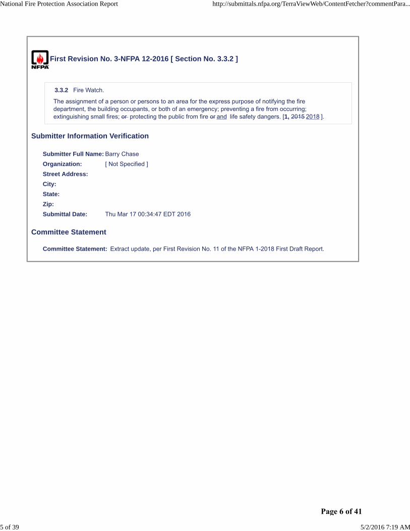
3.3.2 Fire Watch.
The assignment of a person or persons to an area for the express purpose of notifying the firedepartment, the building occupants, or both of an emergency; preventing a fire from occurring;extinguishing small fires; or protecting the public from fire or and life safety dangers. [1, 2015 2018 ].
Submitter Information Verification
Submitter Full Name: Barry Chase
Organization: [ Not Specified ]
Street Address:
City:
State:
Zip:
Submittal Date: Thu Mar 17 00:34:47 EDT 2016
Committee Statement
Committee Statement: Extract update, per First Revision No. 11 of the NFPA 1-2018 First Draft Report.
National Fire Protection Association Report http://submittals.nfpa.org/TerraViewWeb/ContentFetcher?commentPara...
5 of 39 5/2/2016 7:19 AM
Page 6 of 41

First Revision No. 4-NFPA 12-2016 [ Section No. 3.3.3 ]
3.3.3 Inspection.
A visible visual examination of a system or portion thereof to verify that it appears to be in operatingcondition and is free of physical damage. [820, 2012 2016 ]
Submitter Information Verification
Submitter Full Name: Barry Chase
Organization: [ Not Specified ]
Street Address:
City:
State:
Zip:
Submittal Date: Thu Mar 17 00:39:18 EDT 2016
Committee Statement
Committee Statement: Extract correction and update.
Public Input No. 8-NFPA 12-2015 [Section No. 3.3.3]
National Fire Protection Association Report http://submittals.nfpa.org/TerraViewWeb/ContentFetcher?commentPara...
6 of 39 5/2/2016 7:19 AM
Page 7 of 41
First Revision No. 5-NFPA 12-2016 [ Section No. 4.3.2.2 ]
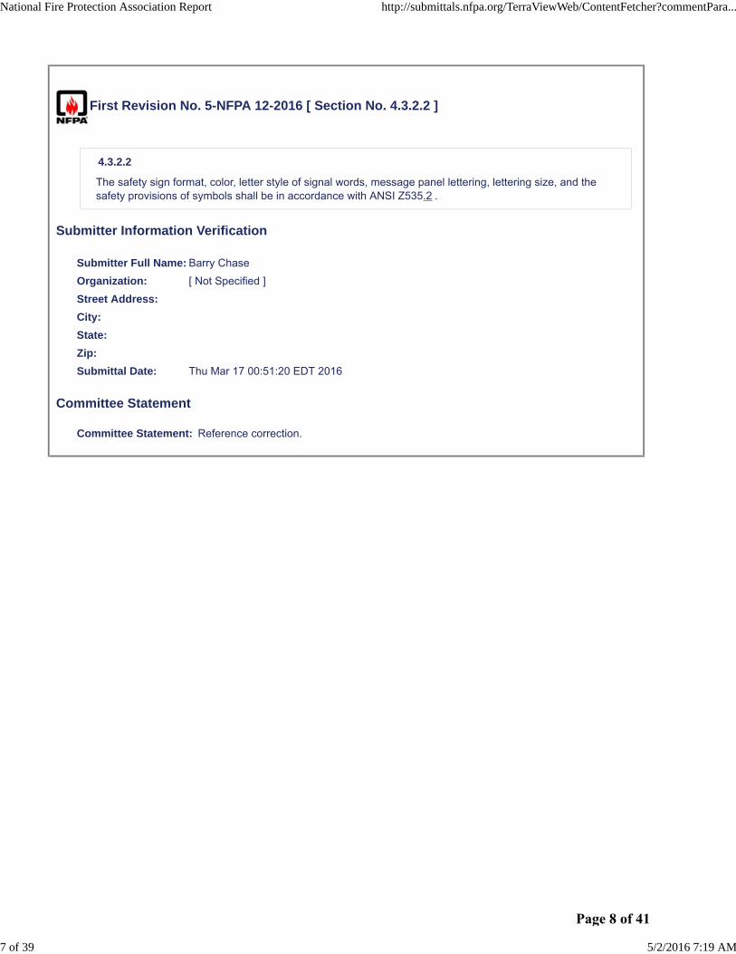
4.3.2.2
The safety sign format, color, letter style of signal words, message panel lettering, lettering size, and thesafety provisions of symbols shall be in accordance with ANSI Z535.2 .
Submitter Information Verification
Submitter Full Name: Barry Chase
Organization: [ Not Specified ]
Street Address:
City:
State:
Zip:
Submittal Date: Thu Mar 17 00:51:20 EDT 2016
Committee Statement
Committee Statement: Reference correction.
National Fire Protection Association Report http://submittals.nfpa.org/TerraViewWeb/ContentFetcher?commentPara...
7 of 39 5/2/2016 7:19 AM
Page 8 of 41
First Revision No. 6-NFPA 12-2016 [ New Section after 4.4.1.2 ]
4.4.1.3
Integrated fire protection and life safety system testing shall be in accordance with NFPA 4 .
Submitter Information Verification
Submitter Full Name: Barry Chase
Organization: [ Not Specified ]
Street Address:
City:
State:
Zip:
Submittal Date: Fri Mar 18 10:00:11 EDT 2016
Committee Statement
CommitteeStatement:
Many installations utilize various individual systems (fire suppression, fire alarm or signaling system,emergency communication system, fire doors, dampers, elevators, smoke control, HVAC,supervising station, etc.) for fire protection and life safety, where each may utilize their own code,standard, or acceptance criteria. NFPA 4 is a new standard that provides requirements for testingintegrated systems together so that the entire fire protection and life safety system objective isaccomplished.
ResponseMessage:
Public Input No. 22-NFPA 12-2016 [New Section after 4.4.1.2]
National Fire Protection Association Report http://submittals.nfpa.org/TerraViewWeb/ContentFetcher?commentPara...
8 of 39 5/2/2016 7:19 AM
Page 9 of 41

First Revision No. 27-NFPA 12-2016 [ Section No. 4.5.4.8.1 ]
4.5.4.8.1
Manual controls shall not require a pull of more than 40 lb lbf (force) (178 N) nor a movement of morethan 14 in. (356 mm) to secure operation.
Submitter Information Verification
Submitter Full Name: Barry Chase
Organization: National Fire Protection Assoc
Street Address:
City:
State:
Zip:
Submittal Date: Fri Apr 08 10:39:08 EDT 2016
Committee Statement
Committee Statement: The unit, "lb (force)," was changed to "lbf" to comply with the Manual of Style.
Response Message:
National Fire Protection Association Report http://submittals.nfpa.org/TerraViewWeb/ContentFetcher?commentPara...
9 of 39 5/2/2016 7:19 AM
Page 10 of 41

First Revision No. 17-NFPA 12-2016 [ Section No. 4.5.5.3 ]
4.5.5.3*
Interconnections between the components that are necessary for the control of the system and life safetyshall be supervised.
Exception: Normally unpressurized interconnections of pipe and tube shall not be required to besupervised.
4.5.5.4
Normally unpressurized interconnections of pipe and tube shall not be required to be supervised complywith 4.5.5.3 .
Submitter Information Verification
Submitter Full Name: Barry Chase
Organization: National Fire Protection Assoc
Street Address:
City:
State:
Zip:
Submittal Date: Thu Apr 07 13:54:24 EDT 2016
Committee Statement
CommitteeStatement:
The section was revised to eliminate the exception, in accordance with the Manual ofStyle.
Response Message:
National Fire Protection Association Report http://submittals.nfpa.org/TerraViewWeb/ContentFetcher?commentPara...
10 of 39 5/2/2016 7:19 AM
Page 11 of 41

First Revision No. 7-NFPA 12-2016 [ Section No. 4.7.1.5.1.3 ]
4.7.1.5.1.3
Flanged joints downstream of stop valves or in systems with no stop valves shall be permitted to beClass 300. Threaded unions shall, as a minimum, be equivalent to Class 2000 forged steel.
4.7.1.5.1.4
Threaded unions shall, as a minimum, be equivalent to Class 2000 forged steel.
Submitter Information Verification
Submitter Full Name: Barry Chase
Organization: [ Not Specified ]
Street Address:
City:
State:
Zip:
Submittal Date: Fri Mar 18 10:02:24 EDT 2016
Committee Statement
Committee Statement: The paragraph is broken into two sections, per the Manual of Style.
Response Message:
Public Input No. 20-NFPA 12-2016 [Section No. 4.7.1.5.1.3]
Public Input No. 21-NFPA 12-2016 [Section No. 4.7.1.5.1.4]
National Fire Protection Association Report http://submittals.nfpa.org/TerraViewWeb/ContentFetcher?commentPara...
11 of 39 5/2/2016 7:19 AM
Page 12 of 41

First Revision No. 18-NFPA 12-2016 [ Section No. 4.7.1.6.3 ]
4.7.1.6.3
Where hex bushings are used for one pipe size reduction, a Class 3000 lb (207 bar) steel bushing shallbe provided to maintain adequate strength.
Submitter Information Verification
Submitter Full Name: Barry Chase
Organization: National Fire Protection Assoc
Street Address:
City:
State:
Zip:
Submittal Date: Thu Apr 07 14:00:55 EDT 2016
Committee Statement
CommitteeStatement:
The appropriate term for these fittings is "Class 3000," not "3000 lb." The metric conversionwas deleted, as it is not applicable.
ResponseMessage:
National Fire Protection Association Report http://submittals.nfpa.org/TerraViewWeb/ContentFetcher?commentPara...
12 of 39 5/2/2016 7:19 AM
Page 13 of 41

First Revision No. 9-NFPA 12-2016 [ Section No. 4.7.2 [Excluding any Sub-Sections] ]
The piping system shall be securely supported with due allowance for agent thrust forces and thermalexpansion and contraction and shall not be subject to mechanical, chemical, or other damage.
Submitter Information Verification
Submitter Full Name: Barry Chase
Organization: [ Not Specified ]
Street Address:
City:
State:
Zip:
Submittal Date: Fri Mar 18 10:09:41 EDT 2016
Committee Statement
CommitteeStatement:
This revision removes unenforceable language. The requirements for hanging and bracingare now located in 4.7.6 (FR 16).
Annex A.4.7.2 is deleted. A mandatory reference to ANSI B31.1 is included in the new section4.7.6.
ResponseMessage:
Public Input No. 16-NFPA 12-2015 [Section No. 4.7.2 [Excluding any Sub-Sections]]
Public Input No. 19-NFPA 12-2015 [Section No. A.4.7.2]
National Fire Protection Association Report http://submittals.nfpa.org/TerraViewWeb/ContentFetcher?commentPara...
13 of 39 5/2/2016 7:19 AM
Page 14 of 41
First Revision No. 10-NFPA 12-2016 [ Section No. 4.7.2.1 ]
4.7.2.1
Where explosions are possible, the piping system shall be hung from supports that are least likely to bedisplaced.
Submitter Information Verification
Submitter Full Name: Barry Chase
Organization: [ Not Specified ]
Street Address:
City:
State:
Zip:
Submittal Date: Fri Mar 18 10:13:22 EDT 2016
Committee Statement
Committee Statement: Removes unenforceable language.
Response Message:
Public Input No. 17-NFPA 12-2015 [Section No. 4.7.2.1]
National Fire Protection Association Report http://submittals.nfpa.org/TerraViewWeb/ContentFetcher?commentPara...
14 of 39 5/2/2016 7:19 AM
Page 15 of 41
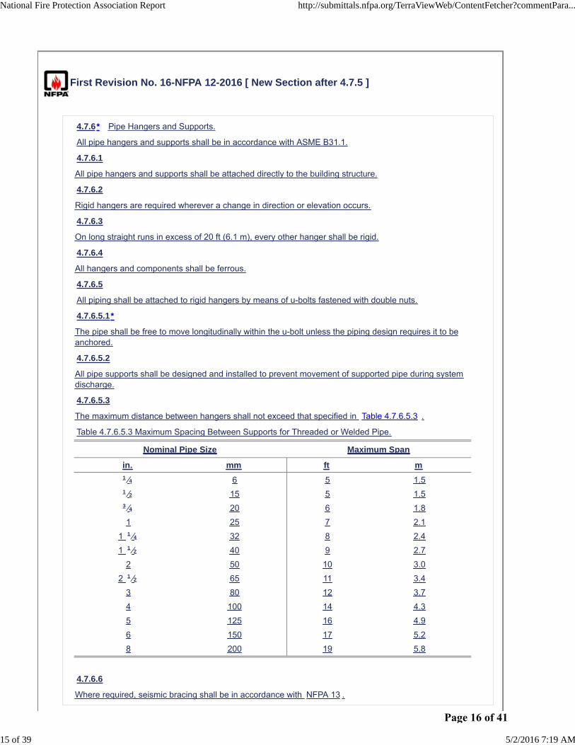
First Revision No. 16-NFPA 12-2016 [ New Section after 4.7.5 ]
4.7.6* Pipe Hangers and Supports.
All pipe hangers and supports shall be in accordance with ASME B31.1.
4.7.6.1
All pipe hangers and supports shall be attached directly to the building structure.
4.7.6.2
Rigid hangers are required wherever a change in direction or elevation occurs.
4.7.6.3
On long straight runs in excess of 20 ft (6.1 m), every other hanger shall be rigid.
4.7.6.4
All hangers and components shall be ferrous.
4.7.6.5
All piping shall be attached to rigid hangers by means of u-bolts fastened with double nuts.
4.7.6.5.1*
The pipe shall be free to move longitudinally within the u-bolt unless the piping design requires it to beanchored.
4.7.6.5.2
All pipe supports shall be designed and installed to prevent movement of supported pipe during systemdischarge.
4.7.6.5.3
The maximum distance between hangers shall not exceed that specified in Table 4.7.6.5.3 .
Table 4.7.6.5.3 Maximum Spacing Between Supports for Threaded or Welded Pipe.
Nominal Pipe Size Maximum Span
in. mm ft m1 ⁄4 6 5 1.51 ⁄2 15 5 1.53 ⁄4 20 6 1.8
1 25 7 2.1
1 1 ⁄4 32 8 2.4
1 1 ⁄2 40 9 2.7
2 50 10 3.0
2 1 ⁄2 65 11 3.4
3 80 12 3.7
4 100 14 4.3
5 125 16 4.9
6 150 17 5.2
8 200 19 5.8
4.7.6.6
Where required, seismic bracing shall be in accordance with NFPA 13 .
National Fire Protection Association Report http://submittals.nfpa.org/TerraViewWeb/ContentFetcher?commentPara...
15 of 39 5/2/2016 7:19 AM
Page 16 of 41
Supplemental Information
File Name Description
12-FR_16.docx Annex material and new table
Submitter Information Verification
Submitter Full Name: Barry Chase
Organization: [ Not Specified ]
Street Address:
City:
State:
Zip:
Submittal Date: Fri Mar 18 15:07:00 EDT 2016
Committee Statement
CommitteeStatement:
Presently there is little guidance on the proper support of CO2 system piping (low pressure systemsonly – see Section 4.7.2) and no guidance for support of high pressure systems at all. Due to thepotential for pipe movement and dislodgement due to agent forces and thermalexpansion/contraction, there is a need to specify rigid pipe supports at critical points of the systemand dead weight support for the remainder of the system piping. There are no requirementspresently for seismic bracing of CO2 system piping.
ResponseMessage:
Public Input No. 18-NFPA 12-2015 [New Section after 4.7.5.3.2]
National Fire Protection Association Report http://submittals.nfpa.org/TerraViewWeb/ContentFetcher?commentPara...
16 of 39 5/2/2016 7:19 AM
Page 17 of 41

1) INSERT ANNEX A.4.7.6
A.4.7.6 The FSSA Pipe Design Guide for Use with Special Hazard Fire Suppression Systems provides guidance on pipe supports.
2) INSERT ANNEX A.4.7.6.5.1
A.4.7.6.5.1 Hangers and pipe should be designed to allow longitudinal movement due to agent thrust forces and thermal expansion.
3) INSERT TABLE 4.7.6.5.3
Table 4.7.6.5.3 Maximum Spacing Between Supports For Threaded or Welded Pipe.
Nominal Pipe Size Maximum Span
in. mm ft m
1/4 6 5 1.5 1/2 15 5 1.5 3/4 20 6 1.8 1 25 7 2.1
1 1/4 32 8 2.4 1 1/2 40 9 2.7
2 50 10 3.0 2 1/2 65 11 3.4
3 80 12 3.7 4 100 14 4.3 5 125 16 4.9 6 150 17 5.2 8 200 19 5.8
Page 18 of 41

First Revision No. 11-NFPA 12-2016 [ Section No. 5.3.2.2 ]
National Fire Protection Association Report http://submittals.nfpa.org/TerraViewWeb/ContentFetcher?commentPara...
17 of 39 5/2/2016 7:19 AM
Page 19 of 41

5.3.2.2*
National Fire Protection Association Report http://submittals.nfpa.org/TerraViewWeb/ContentFetcher?commentPara...
18 of 39 5/2/2016 7:19 AM
Page 20 of 41

Table 5.3.2.2 shall be used to determine the minimum carbon dioxide concentrations for the liquids andgases shown in the table.
Table 5.3.2.2 Minimum Carbon Dioxide Concentrations for Extinguishment
Material
Theoretical
Minimum CO2
Concentration
(%)
Minimum
Design CO2
Concentration
(%)
Acetylene 55 66
Acetone 27* 34
Aviation gas grades
115/14530 36
Benzol, benzene 31 37
Butadiene 34 41
Butane 28 34
Butane-I 31 37
Carbon disulfide 60 72
Carbon monoxide 53 64
Coal or natural gas 31* 37
Cyclopropane 31 37
Diethyl ether 33 40
Dimethyl ether 33 40
Dowtherm 38* 46
Ethane 33 40
Ethyl alcohol 36 43
Ethyl ether 38* 46
Ethylene 41 49
Ethylene dichloride 21 34
Ethylene oxide 44 53
Gasoline 28 34
Hexane 29 35
Higher paraffin
hydrocarbons Cn H2m 2n+2 , + 2m - n≥ 528 34
Hydrogen 62 75
Hydrogen sulfide 30 36
Isobutane 30* 36
Isobutylene 26 34
Isobutyl formate 26 34
JP-4 30 36
Kerosene 28 34
Methane 25 34
Methyl acetate 29 35
Methyl alcohol 33 40
Methyl butene-I 30 36
Methyl ethyl ketone 33 40
Methyl formate 32 39
National Fire Protection Association Report http://submittals.nfpa.org/TerraViewWeb/ContentFetcher?commentPara...
19 of 39 5/2/2016 7:19 AM
Page 21 of 41

Material
Theoretical
Minimum CO2
Concentration
(%)
Minimum
Design CO2
Concentration
(%)
Pentane 29 35
Propane 30 36
Propylene 30 36
Quench, lube oils 28 34
Note: The theoretical minimum extinguishing concentrations in air for the materials in the table wereobtained from a compilation of Bureau of Mines, Bulletins 503 and 627.
*Calculated from accepted residual oxygen values.
Supplemental Information
File Name Description
12-FR_11.docx FOR STAFF USE
Submitter Information Verification
Submitter Full Name: Barry Chase
Organization: [ Not Specified ]
Street Address:
City:
State:
Zip:
Submittal Date: Fri Mar 18 10:17:02 EDT 2016
Committee Statement
CommitteeStatement:
The intended “Higher paraffin” text is from the caption of Figure 35 of U.S. Bureau of Mines Bulletin627.
The “Higher paraffin” line, with n = 6 (hexane), has a column #2 value = 28 % (and MDC = 34 %),while directly above is “Hexane” with a column #2 value = 29 % (and MDC = 35 %). Thus, the“Hexane” line and the “Higher paraffin” line are in conflict. Close examination of the hexaneflammability data in both U.S. Bureau of Mines Bulletins 503 and 627 clearly indicates that the 28 %for hexane “Minimum Theoretical Concentration” is correct.
ResponseMessage:
Public Input No. 11-NFPA 12-2015 [Section No. 5.3.2.2]
National Fire Protection Association Report http://submittals.nfpa.org/TerraViewWeb/ContentFetcher?commentPara...
20 of 39 5/2/2016 7:19 AM
Page 22 of 41
First Revision No. 19-NFPA 12-2016 [ Section No. A.4.4.3.2 ]
A.4.4.3.2
FM Approvals 5420, Approval Standard for Carbon Dioxide Extinguishing Systems , should be consultedfor possible listing requirements.
Submitter Information Verification
Submitter Full Name: Barry Chase
Organization: National Fire Protection Assoc
Street Address:
City:
State:
Zip:
Submittal Date: Thu Apr 07 14:07:10 EDT 2016
Committee Statement
CommitteeStatement:
The referenced document title was removed for consistency. All other references use theshortened form.
Response Message:
National Fire Protection Association Report http://submittals.nfpa.org/TerraViewWeb/ContentFetcher?commentPara...
21 of 39 5/2/2016 7:19 AM
Page 23 of 41
First Revision No. 21-NFPA 12-2016 [ Section No. A.4.5.3 ]
A.4.5.3
Detectors installed at the maximum spacing as listed or approved for fire alarm use can result inexcessive delay in agent release.
For additional information on detectors, refer to NFPA 72.
The FSSA Application Guide Detection & Control for Fire Suppression Systems offers the designerinformation on the various types of detection and control equipment.
Submitter Information Verification
Submitter Full Name: Barry Chase
Organization: National Fire Protection Assoc
Street Address:
City:
State:
Zip:
Submittal Date: Thu Apr 07 14:16:07 EDT 2016
Committee Statement
Committee Statement: The section was revised to italicize "FSSA," as it is part of the referenced document title.
Response Message:
National Fire Protection Association Report http://submittals.nfpa.org/TerraViewWeb/ContentFetcher?commentPara...
22 of 39 5/2/2016 7:19 AM
Page 24 of 41
First Revision No. 22-NFPA 12-2016 [ Section No. A.4.6.5.2 ]
A.4.6.5.2
Transporting a charged cylinder might be illegal if the cylinder has been damaged or exposed to fire.Federal and local regulations should be consulted.
The Fire Suppression Systems Association publication, FSSA Test Guide for Use with Special Hazard FireSuppression Systems Containers, provides useful information on testing requirements and safetyprecautions for handling and transporting high-pressure carbon dioxide cylinders.
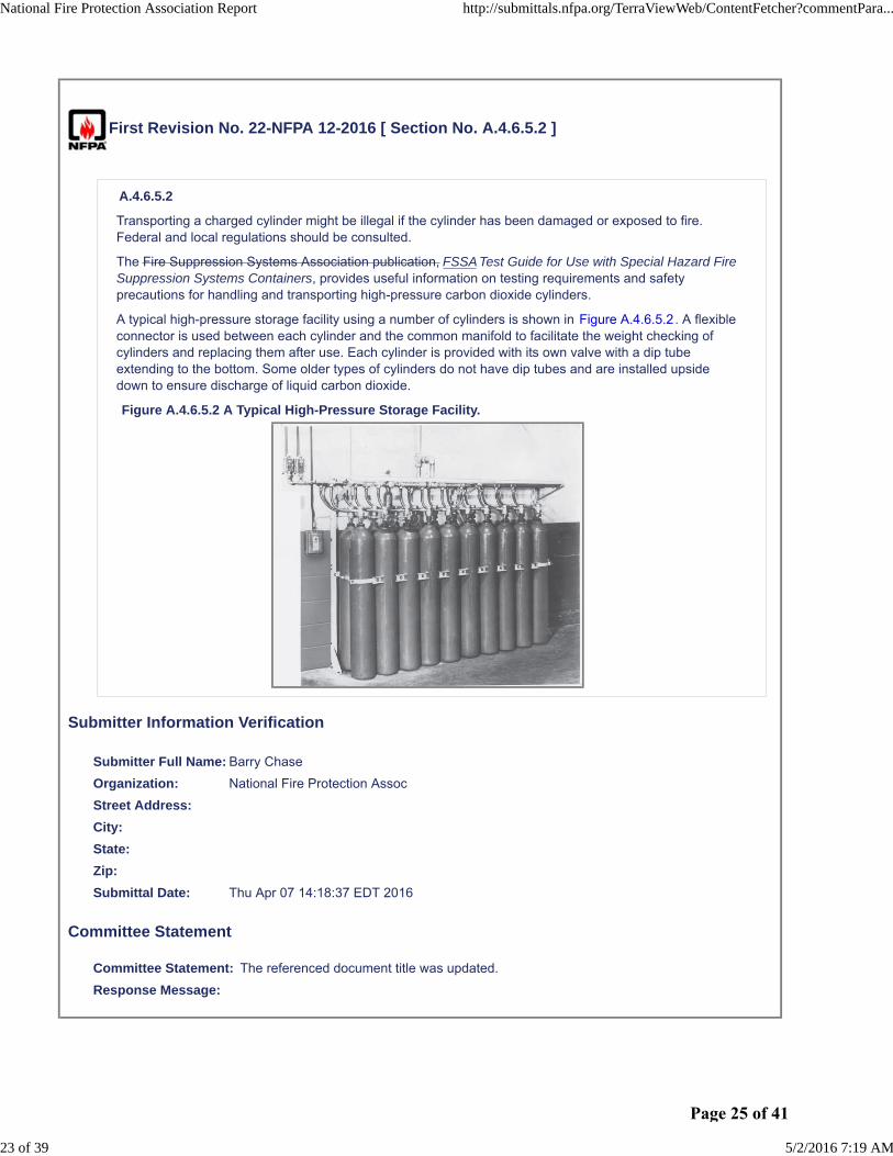
A typical high-pressure storage facility using a number of cylinders is shown in Figure A.4.6.5.2. A flexibleconnector is used between each cylinder and the common manifold to facilitate the weight checking ofcylinders and replacing them after use. Each cylinder is provided with its own valve with a dip tubeextending to the bottom. Some older types of cylinders do not have dip tubes and are installed upsidedown to ensure discharge of liquid carbon dioxide.
Figure A.4.6.5.2 A Typical High-Pressure Storage Facility.
Submitter Information Verification
Submitter Full Name: Barry Chase
Organization: National Fire Protection Assoc
Street Address:
City:
State:
Zip:
Submittal Date: Thu Apr 07 14:18:37 EDT 2016
Committee Statement
Committee Statement: The referenced document title was updated.
Response Message:
National Fire Protection Association Report http://submittals.nfpa.org/TerraViewWeb/ContentFetcher?commentPara...
23 of 39 5/2/2016 7:19 AM
Page 25 of 41
First Revision No. 23-NFPA 12-2016 [ Section No. A.4.7.1.7.1 ]
A.4.7.1.7.1
In performing the calculation to determine pipe thickness, the guidelines provided in the FSSApublication, Pipe Design Handbook for Use with Special Hazard Fire Suppression Systems should beconsulted.
Submitter Information Verification
Submitter Full Name: Barry Chase
Organization: National Fire Protection Assoc
Street Address:
City:
State:
Zip:
Submittal Date: Thu Apr 07 14:20:26 EDT 2016
Committee Statement
Committee Statement: The referenced document title was updated.
Response Message:
National Fire Protection Association Report http://submittals.nfpa.org/TerraViewWeb/ContentFetcher?commentPara...
24 of 39 5/2/2016 7:19 AM
Page 26 of 41

First Revision No. 24-NFPA 12-2016 [ Section No. A.4.8.3.3 ]
A.4.8.3.3
The maintenance report provides the owner with valuable information pertaining to the fire system, itscondition, and recommendations. The servicing company should review its maintenance report to ensurethat it captures the necessary data and performs the maintenance in a thorough and safe manner. TheFire Suppression Systems Association publication FSSA Fire Protection Systems Inspection FormGuidelines can be used to evaluate the service company’s maintenance report.
Submitter Information Verification
Submitter Full Name: Barry Chase
Organization: National Fire Protection Assoc
Street Address:
City:
State:
Zip:
Submittal Date: Thu Apr 07 14:21:43 EDT 2016
Committee Statement
Committee Statement: The referenced document title was updated.
Response Message:
National Fire Protection Association Report http://submittals.nfpa.org/TerraViewWeb/ContentFetcher?commentPara...
25 of 39 5/2/2016 7:19 AM
Page 27 of 41

First Revision No. 25-NFPA 12-2016 [ Section No. A.6.4.1 ]
A.6.4.1
The practical application of the rate-by-area method is explained in the FSSA Design Guidelines forCarbon Dioxide Local Application Rate-by-Area. The guide assists the user through the entire process ofa rate-by-area CO2 system design with examples. The user will gain an understanding of the steps
involved with the layout, calculation, and overall design of the system.
Submitter Information Verification
Submitter Full Name: Barry Chase
Organization: National Fire Protection Assoc
Street Address:
City:
State:
Zip:
Submittal Date: Thu Apr 07 14:22:57 EDT 2016
Committee Statement
Committee Statement: The section was revised to italicize "FSSA," as it is part of the referenced document title.
Response Message:
National Fire Protection Association Report http://submittals.nfpa.org/TerraViewWeb/ContentFetcher?commentPara...
26 of 39 5/2/2016 7:19 AM
Page 28 of 41

First Revision No. 26-NFPA 12-2016 [ Section No. A.6.5.1 ]
A.6.5.1
The practical application of the rate-by-volume method is complicated. The design of a system can beaided by examples and a walk-through calculation of a system. The guide, FSSA Design Guidelines forCarbon Dioxide Local Application Rate-by-Volume describes how to design a carbon dioxide system usingthe rate-by-volume method.
Submitter Information Verification
Submitter Full Name: Barry Chase
Organization: National Fire Protection Assoc
Street Address:
City:
State:
Zip:
Submittal Date: Thu Apr 07 14:23:54 EDT 2016
Committee Statement
Committee Statement: The section was revised to italicize "FSSA," as it is part of the referenced document title.
Response Message:
National Fire Protection Association Report http://submittals.nfpa.org/TerraViewWeb/ContentFetcher?commentPara...
27 of 39 5/2/2016 7:19 AM
Page 29 of 41

First Revision No. 20-NFPA 12-2016 [ Section No. B.1 ]
B.1 Introduction.
The following annex material is provided to show typical examples of how various fire hazards can beprotected with fixed carbon dioxide extinguishing systems. It should be noted that the methods describedare not to be construed as being the only ones that can be used. They are meant to help only ininterpreting and elaborating on the intent of the standard where proper application could be subject toquestion.
Submitter Information Verification
Submitter Full Name: Barry Chase
Organization: National Fire Protection Assoc
Street Address:
City:
State:
Zip:
Submittal Date: Thu Apr 07 14:12:00 EDT 2016
Committee Statement
Committee Statement: A section title was added for consistency with the remainder of the chapter.
Response Message:
National Fire Protection Association Report http://submittals.nfpa.org/TerraViewWeb/ContentFetcher?commentPara...
28 of 39 5/2/2016 7:19 AM
Page 30 of 41

First Revision No. 13-NFPA 12-2016 [ Section No. C.1 ]
National Fire Protection Association Report http://submittals.nfpa.org/TerraViewWeb/ContentFetcher?commentPara...
29 of 39 5/2/2016 7:19 AM
Page 31 of 41

C.1
National Fire Protection Association Report http://submittals.nfpa.org/TerraViewWeb/ContentFetcher?commentPara...
30 of 39 5/2/2016 7:19 AM
Page 32 of 41

Computing pipe sizes for carbon dioxide systems is complicated by the fact that the pressure drop isnonlinear with respect to the pipeline. Carbon dioxide leaves the storage vessel as a liquid at saturationpressure. As the pressure drops due to pipeline friction, the liquid boils and produces a mixture of liquidand vapor. Consequently, the volume of the flowing mixture increases and the velocity of flow must alsoincrease. Thus, the pressure drop per unit length of pipe is greater near the end of the pipeline than it is atthe beginning.
Pressure drop information for designing piping systems can best be obtained from curves of pressureversus equivalent length for various flow rates and pipe sizes. Such curves can be plotted using thetheoretical equation given in 4.7.5.1. The Y and Z factors in the equation in that paragraph depend onstorage pressure and line pressure. In the following equations, Z is a dimensionless ratio, and the Y factorhas units of pressure times density and will therefore change the system of units. The Y and Z factors canbe evaluated as follows:
[C.1a]
where:
P = pressure at end of pipeline [psi (kPa)]
P1 = storage pressure [psi (kPa)]
ρ = density at pressure P [lb/ft3 (kg/m3)]
ρ1 = density at pressure P1 [lb/ft3 (kg/m3)]
ln = natural logarithm
The storage pressure is an important factor in carbon dioxide flow. In low-pressure storage, the startingpressure in the storage vessel will recede to a lower level, depending on whether all or only part of thesupply is discharged. Because of this, the average pressure during discharge will be about 285 psi(1965 kPa). The flow equation is based on absolute pressure; therefore, 300 psi (2068 kPa) is used forcalculations involving low-pressure systems.
In high-pressure systems, the storage pressure depends on the ambient temperature. Normal ambienttemperature is assumed to be 70°F (21°C). For this condition, the average pressure in the cylinder duringdischarge of the liquid portion will be about 750 psi (5171 kPa). This pressure has therefore been selectedfor calculations involving high-pressure systems.
Using the base pressures of 300 psi (2068 kPa) and 750 psi (5171 kPa), values have been determined forthe Y and Z factors in the flow equation. These values are listed in Table C.1(a) and Table C.1(b).
Table C.1(a) Values of Y and Z for 300 psi Initial Storage Pressure
Y
Pressure
(psi) Z 0 1 2 3 4 5 6 7 8 9
300 0.000 0 0 0 0 0 0 0 0 0 0
290 0.135 596 540 483 426 367 308 248 187 126 63
280 0.264 1119 1070 1020 969 918 866 814 760 706 652
270 0.387 1580 1536 1492 1448 1402 1357 1310 1263 1216 1168
260 0.505 1989 1950 1911 1871 1831 1790 1749 1708 1666 1623
250 0.620 2352 2318 2283 2248 2212 2176 2139 2102 2065 2027
240 0.732 2677 2646 2615 2583 2552 2519 2487 2454 2420 2386
230 0.841 2968 2940 2912 2884 2855 2826 2797 2768 2738 2708
220 0.950 3228 3204 3179 3153 3128 3102 3075 3049 3022 2995
National Fire Protection Association Report http://submittals.nfpa.org/TerraViewWeb/ContentFetcher?commentPara...
31 of 39 5/2/2016 7:19 AM
Page 33 of 41

Y
Pressure
(psi) Z 0 1 2 3 4 5 6 7 8 9
210 1.057 3462 3440 3418 3395 3372 3349 3325 3301 3277 3253
200 1.165 3673 3653 3632 3612 3591 3570 3549 3528 3506 3485
190 1.274 3861 3843 3825 3807 3788 3769 3750 3731 3712 3692
180 1.384 4030 4014 3998 3981 3965 3948 3931 3914 3896 3879
170 1.497 4181 4167 4152 4138 4123 4108 4093 4077 4062 4046
160 1.612 4316 4303 4291 4277 4264 4251 4237 4223 4210 4196
150 1.731 4436 4425 4413 4402 4390 4378 4366 4354 4341 4329
Table C.1(b) Values of Y and Z for 750 psi Initial Storage Pressure
Y
Pressure
(psi) Z 0 1 2 3 4 5 6 7 8 9
750 0.000 0 0 0 0 0 0 0 0 0 0
740 0.038 497 448 399 350 300 251 201 151 101 51
730 0.075 975 928 881 833 786 738 690 642 594 545
720 0.110 1436 1391 1345 1299 1254 1208 1161 1115 1068 1022
710 0.143 1882 1838 1794 1750 1706 1661 1616 1572 1527 1481
700 0.174 2314 2271 2229 2186 2143 2100 2057 2013 1970 1926
690 0.205 2733 2691 2650 2608 2567 2525 2483 2441 2399 2357
680 0.235 3139 3099 3059 3018 2978 2937 2897 2856 2815 2774
670 0.265 3533 3494 3455 3416 3377 3338 3298 3259 3219 3179
660 0.296 3916 3878 3840 3802 3764 3726 3688 3649 3611 3572
650 0.327 4286 4250 4213 4176 4139 4102 4065 4028 3991 3953
640 0.360 4645 4610 4575 4539 4503 4467 4431 4395 4359 4323
630 0.393 4993 4959 4924 4890 4855 4821 4786 4751 4716 4681
620 0.427 5329 5296 5263 5229 5196 5162 5129 5095 5061 5027
610 0.462 5653 5621 5589 5557 5525 5493 5460 5427 5395 5362
600 0.498 5967 5936 5905 5874 5843 5811 5780 5749 5717 5685
590 0.535 6268 6239 6209 6179 6149 6119 6089 6058 6028 5997
580 0.572 6560 6531 6502 6473 6444 6415 6386 6357 6328 6298
570 0.609 6840 6812 6785 6757 6729 6701 6673 6645 6616 6588
560 0.646 7110 7084 7057 7030 7003 6976 6949 6922 6895 6868
550 0.683 7371 7345 7320 7294 7268 7242 7216 7190 7163 7137
540 0.719 7622 7597 7572 7548 7523 7498 7472 7447 7422 7396
530 0.756 7864 7840 7816 7792 7768 7744 7720 7696 7671 7647
520 0.792 8098 8075 8052 8028 8005 7982 7958 7935 7911 7888
510 0.827 8323 8301 8278 8256 8234 8211 8189 8166 8143 8120
500 0.863 8540 8519 8497 8476 8454 8433 8411 8389 8367 8345
490 0.898 8750 8730 8709 8688 8667 8646 8625 8604 8583 8562
480 0.933 8953 8933 8913 8893 8873 8852 8832 8812 8791 8771
470 0.967 9149 9129 9110 9091 9071 9052 9032 9012 8993 8973
460 1.002 9338 9319 9301 9282 9263 9244 9225 9206 9187 9168
450 1.038 9520 9502 9484 9466 9448 9430 9412 9393 9375 9356
National Fire Protection Association Report http://submittals.nfpa.org/TerraViewWeb/ContentFetcher?commentPara...
32 of 39 5/2/2016 7:19 AM
Page 34 of 41

Y
Pressure
(psi) Z 0 1 2 3 4 5 6 7 8 9
440 1.073 9697 9680 9662 9644 9627 9609 9592 9574 9556 9538
430 1.109 9866 9850 9833 9816 9799 9782 9765 9748 9731 9714
420 1.146 10030 10014 9998 9982 9966 9949 9933 9916 9900 9883
410 1.184 10188 10173 10157 10141 10126 10110 10094 10078 10062 10046
400 1.222 10340 10325 10310 10295 10280 10265 10250 10234 10219 10204
390 1.262 10486 10472 10458 10443 10429 10414 10399 10385 10370 10355
380 1.302 10627 10613 10599 10585 10571 10557 10543 10529 10515 10501
370 1.344 10762 10749 10735 10722 10708 10695 10681 10668 10654 10641
360 1.386 10891 10878 10866 10853 10840 10827 10814 10801 10788 10775
350 1.429 11015 11003 10991 10978 10966 10954 10941 10929 10916 10904
340 1.473 11134 11122 11110 11099 11087 11075 11063 11051 11039 11027
330 1.518 11247 11236 11225 11214 11202 11191 11180 11168 11157 11145
320 1.564 11356 11345 11334 11323 11313 11302 11291 11280 11269 11258
310 1.610 11459 11449 11439 11428 11418 11408 11398 11387 11377 11366
300 1.657 11558 11548 11539 11529 11519 11509 11499 11489 11479 11469
For practical application, it is desirable to plot curves for each pipe size that can be used. However, theflow equation can be rearranged as shown in the following equation:
[C.1b]
Thus, by plotting values of L/D1.25 and Q/D2, it is possible to use one family of curves for any pipe size.Figure C.1(a) gives flow information for 0°F (−18°C) storage temperature on this basis. Figure C.1(b)gives similar information for high-pressure storage at 70°F (21°C). For an inside pipe diameter of exactly
1 in., D2 and D1.25 reduce to unity and cancel out. For other pipe sizes, it is necessary to convert the flowrate and equivalent length by dividing or multiplying by these factors. Table C.1(c) gives values for D.
Figure C.1(a) Pressure Drop in Pipeline for 300 psi (2068 kPa) Storage Pressure.
Figure C.1(b) Pressure Drop in Pipeline for 750 psi (5171 kPa) Storage Pressure.
National Fire Protection Association Report http://submittals.nfpa.org/TerraViewWeb/ContentFetcher?commentPara...
33 of 39 5/2/2016 7:19 AM
Page 35 of 41

Table C.1(c) Values of D1.25 and D2 for Various Pipe Sizes
Pipe Size
and Type
Inside Diameter
(in.) D1.25 D2
1⁄2 Std. 0.622 0.5521 0.38693⁄4 Std. 0.824 0.785 0.679
1 Std. 1.049 1.0615 1.100
1 XH 0.957 0.9465 0.9158
11⁄4 Std. 1.380 1.496 1.904
11⁄4 XH 1.278 1.359 1.633
11⁄2 Std. 1.610 1.813 2.592
11⁄2 XH 1.500 1.660 2.250
2 Std. 2.067 2.475 4.272
2 XH 1.939 2.288 3.760
21⁄2 Std. 2.469 3.09 6.096
21⁄2 XH 2.323 2.865 5.396
3 Std. 3.068 4.06 9.413
3 XH 2.900 3.79 8.410
4 Std. 4.026 5.71 16.21
4 XH 3.826 5.34 14.64
5 Std. 5.047 7.54 25.47
5 XH 4.813 7.14 23.16
6 Std. 6.065 9.50 36.78
6 XH 5.761 8.92 33.19
These curves can be used for designing systems or for checking possible flow rates. For example,assume the problem is to determine the terminal pressure for a low-pressure system consisting of a single2 in. Schedule 40 pipeline with an equivalent length of 500 ft and a flow rate of 1000 lb/min. The flow rateand the equivalent length must be converted to terms of Figure C.1(a) as follows:
[C.1c]
From Figure C.1(a), the terminal pressure is found to be about 228 psi at the point where the interpolatedflow rate of 234 lb/min intersects the equivalent length scale at 201 ft.
If this line terminates in a single nozzle, the equivalent orifice area must be matched to the terminal
National Fire Protection Association Report http://submittals.nfpa.org/TerraViewWeb/ContentFetcher?commentPara...
34 of 39 5/2/2016 7:19 AM
Page 36 of 41

pressure in order to control the flow rate at the desired level of 1000 lb/min. Referring to Table 4.7.5.2.1, it
will be noted that the discharge rate will be 1410 lb/min·in.2 of equivalent orifice area when the orificepressure is 230 psi. The required equivalent orifice area of the nozzle is thus equal to the total flow ratedivided by the rate per square inch, as shown in the following equation:
[C.1d]
From a practical viewpoint, the designer would select a standard nozzle having an equivalent area nearestto the computed area. If the orifice area happened to be a little larger, the actual flow rate would be slightlyhigher and the terminal pressure would be somewhat lower than the estimated 228 psi (1572 kPa).
If, in the previous example, instead of terminating with one large nozzle, the pipeline branched into twosmaller pipelines, it would be necessary to determine the pressure at the end of each branch line. Toillustrate this procedure, assume that the branch lines are equal and consist of 11⁄2 in. Schedule 40 pipewith equivalent lengths of 200 ft (61 m) and that the flow in each branch line is to be 500 lb/min(227 kg/min). Converting to terms used in Figure C.1(a), the following equations result:
[C.1e]
From Figure C.1(a), the starting pressure of 228 psi (1572 kPa) (terminal pressure of main line) intersectsthe flow rate line [193 lb/min (87.6 kg/min)] at an equivalent length of about 300 ft (91.4 m). In otherwords, if the branch line started at the storage vessel, the liquid carbon dioxide would have to flow through300 ft (91.4 m) of pipeline before the pressure dropped to 228 psi (1572 kPa). This length thus becomesthe starting point for the equivalent length of the branch line. The terminal pressure of the branch line isthen found to be 165 psi (1138 kPa) at the point where the 193 lb/min (87.6 kg/min) flow rate lineintersects the total equivalent length line of 410 ft (125 m), or 300 ft + 110 ft (91 m + 34 m). With this newterminal pressure [165 psi (1138 kPa)] and flow rate [500 lb/min (227 kg/min)], the required equivalent
nozzle area at the end of each branch line will be approximately 0.567 in.2 (366 mm2). This is about thesame as the single large nozzle example, except that the discharge rate is cut in half due to the reducedpressure.
The design of the piping distribution system is based on the flow rate desired at each nozzle. This in turndetermines the required flow rate in the branch lines and the main pipeline. From practical experience, it ispossible to estimate the approximate pipe sizes required. The pressure at each nozzle can be determinedfrom suitable flow curves. The nozzle orifice sizes are then selected on the basis of nozzle pressure fromthe data given in 4.7.5.2.
In high-pressure systems, the main header is supplied by a number of separate cylinders. The total flow isthus divided by the number of cylinders to obtain the flow rate from each cylinder. The flow capacity of thecylinder valve and the connector to the header vary with each manufacturer, depending on design andsize. For any particular valve, dip tube, and connector assembly, the equivalent length can be determinedin terms of feet of standard pipe size. With this information, the flow equation can be used to prepare acurve of flow rate versus pressure drop. This curve provides a convenient method of determining headerpressure for a specific valve and connector combination.
Table C.1(d) and Table C.1(e) list the equivalent lengths of pipe fittings for determining the equivalentlength of piping systems. Table C.1(d) is for threaded joints, and Table C.1(e) is for welded joints. Bothtables were computed for Schedule 40 pipe sizes; however, for all practical purposes, the same figurescan also be used for Schedule 80 pipe sizes.
Table C.1(d) Equivalent Lengths in Feet of Threaded Pipe Fitting
Pipe
Size(in.)
ElbowStd.
45Degrees
ElbowStd.
90Degrees
Elbow
90 Degrees Long Radius and TeeThru Flow
Tee
SideUnion Coupling or Gate
Valve
3⁄8 0.6 1.3 0.8 2.7 0.3
National Fire Protection Association Report http://submittals.nfpa.org/TerraViewWeb/ContentFetcher?commentPara...
35 of 39 5/2/2016 7:19 AM
Page 37 of 41

Pipe
Size(in.)
ElbowStd.
45Degrees
ElbowStd.
90Degrees
Elbow
90 Degrees Long Radius and TeeThru Flow
Tee
SideUnion Coupling or Gate
Valve1⁄2 0.8 1.7 1.0 3.4 0.43⁄4 1.0 2.2 1.4 4.5 0.5
1 1.3 2.8 1.8 5.7 0.6
11⁄4 1.7 3.7 2.3 7.5 0.8
11⁄2 2.0 4.3 2.7 8.7 0.9
2 2.6 5.5 3.5 11.2 1.2
21⁄2 3.1 6.6 4.1 13.4 1.4
3 3.8 8.2 5.1 16.6 1.8
4 5.0 10.7 6.7 21.8 2.4
5 6.3 13.4 8.4 27.4 3.0
6 7.6 16.2 10.1 32.8 3.5
For SI units, 1 ft = 0.3048 m.
Table C.1(e) Equivalent Lengths in Feet of Welded Pipe Fitting
Pipe
Size(in.)
Elbow Std. 45Degrees
Elbow Std. 90Degrees
Elbow
90 Degrees Long Radius and TeeThru Flow
Tee
SideGateValve
3⁄8 0.2 0.7 0.5 1.6 0.31⁄2 0.3 0.8 0.7 2.1 0.43⁄4 0.4 1.1 0.9 2.8 0.5
1 0.5 1.4 1.1 3.5 0.6
11⁄4 0.7 1.8 1.5 4.6 0.8
11⁄2 0.8 2.1 1.7 5.4 0.9
2 1.0 2.8 2.2 6.9 1.2
21⁄2 1.2 3.3 2.7 8.2 1.4
3 1.8 4.1 3.3 10.2 1.8
4 2.0 5.4 4.4 13.4 2.4
5 2.5 6.7 5.5 16.8 3.0
6 3.0 8.1 6.6 20.2 3.5
For SI units, 1 ft = 0.3048 m.
For nominal changes in elevation of piping, the change in head pressure is negligible. However, if there isa substantial change in elevation, this factor should be taken into account. The head pressure correctionper foot of elevation depends on the average line pressure where the elevation takes place because thedensity changes with pressure. Correction factors are given in Table C.1(f) and Table C.1(g) forlow-pressure and high-pressure systems, respectively. The correction is subtracted from the terminalpressure when the flow is upward and is added to the terminal pressure when the flow is downward.
Table C.1(f) Elevation Correction Factors for Low-Pressure System
Average Line Pressure Elevation Correction
psi kPa psi/ft kPa/m
300 2068 0.443 10.00
280 1930 0.343 7.76
260 1792 0.265 5.99
240 1655 0.207 4.68
National Fire Protection Association Report http://submittals.nfpa.org/TerraViewWeb/ContentFetcher?commentPara...
36 of 39 5/2/2016 7:19 AM
Page 38 of 41

Average Line Pressure Elevation Correction
psi kPa psi/ft kPa/m
220 1517 0.167 3.78
200 1379 0.134 3.03
180 1241 0.107 2.42
160 1103 0.085 1.92
140 965 0.067 1.52
Table C.1(g) Elevation Correction Factors for High-Pressure System
Average Line Pressure Elevation Correction
psi kPa psi/ft kPa/m
750 5171 0.352 7.96
700 4826 0.300 6.79
650 4482 0.255 5.77
600 4137 0.215 4.86
550 3792 0.177 4.00
500 3447 0.150 3.39
450 3103 0.125 2.83
400 2758 0.105 2.38
350 2413 0.085 1.92
300 2068 0.070 1.58
Supplemental Information
File Name Description
12-FR_13.docx FOR STAFF USE
Submitter Information Verification
Submitter Full Name: Barry Chase
Organization: [ Not Specified ]
Street Address:
City:
State:
Zip:
Submittal Date: Fri Mar 18 10:29:34 EDT 2016
Committee Statement
CommitteeStatement:
The original equations incorrectly uses “D2” (pipe diameter) in the units rather than “in” (inch),which is the correct unit of pipe diameter.
In Table C.1(c), corrected a typo in the second line, which is supposed to be "3/4 in.".
ResponseMessage:
Public Input No. 15-NFPA 12-2015 [Section No. C.1]
National Fire Protection Association Report http://submittals.nfpa.org/TerraViewWeb/ContentFetcher?commentPara...
37 of 39 5/2/2016 7:19 AM
Page 39 of 41
First Revision No. 2-NFPA 12-2016 [ Section No. H.1 ]
H.1 Referenced Publications.
The documents or portions thereof listed in this annex are referenced within the informational sections ofthis standard and are not part of the requirements of this document unless also listed in Chapter 2 forother reasons.
H.1.1 NFPA Publications.
National Fire Protection Association, 1 Batterymarch Park, Quincy, MA 02169-7471.
NFPA 10, Standard for Portable Fire Extinguishers, 2013 2017 edition.
NFPA 69, Standard on Explosion Prevention Systems, 2014 edition.
NFPA 72®, National Fire Alarm and Signaling Code, 2013 2016 edition.
NFPA 77, Recommended Practice on Static Electricity, 2014 edition.
NFPA 96, Standard for Ventilation Control and Fire Protection of Commercial Cooking Operations,2014 2017 edition.
NFPA 101®, Life Safety Code®, 2015 2018 edition.
H.1.2 Other Publications.
H.1.2.1 ASME Publications.
American Society of Mechanical Engineers, Two Park Avenue, New York, NY 10016-5990.
ASME B31.1, Power Piping Code, 2012 2014 .
H.1.2.2 ASTM Publications.
ASTM International, 100 Barr Harbor Drive, P.O. Box C 700, West Conshohocken, PA 19428-2959.
ASTM SI10, American National Standard for Metric Practice, 2010.
H.1.2.3 DHHS Publications.
Department of Health and Human Services, National Institute of Safety and Health, Robert A. TaftLaboratory, 4676 Columbia Parkway, Cincinnati, OH 45226.
DHHS (NIOSH) Publication 76-194, Criteria for a Recommended Standard: Occupational Exposure toCarbon Dioxide,1976.
H.1.2.4 EPA Publications.
Environmental Protection Agency, William Jefferson Clinton East Bldg., 1200 Pennsylvania Avenue, NW,Washington, DC 20460.
EPA 430-R-00-002, “Carbon Dioxide as a Fire Suppressant: Examining the Risks,” February 2000.
H.1.2.5 FM Global Publications.
FM Global, 1175 Boston-Providence Turnpike, P.O. Box 9102, Norwood, MA, 02062.
FM Approvals 5420, Approval Standard for Carbon Dioxide Extinguishing Systems, April 2007.
National Fire Protection Association Report http://submittals.nfpa.org/TerraViewWeb/ContentFetcher?commentPara...
38 of 39 5/2/2016 7:19 AM
Page 40 of 41

H.1.2.6 FSSA Publications.
Fire Suppression Systems Association, 5024-R Campbell Boulevard 3601 E. Joppa Road , Baltimore, MD21234. (www.fssa.net)
FSSA Application Guide Detection & Control for Fire Suppression Systems, November 2010.
FSSA Design Guide for Use with Carbon Dioxide Total Flooding Applications, 1st edition, February 2011.
FSSA Design Guidelines for Carbon Dioxide Local Application Rate by Area, January 2010.
FSSA Design Guidelines for Carbon Dioxide Local Application Rate by Volume, December 2005.
FSSA Fire Protection Systems Inspection Form Guidelines, January 2012.
FSSA Pipe Design Handbook for Use with Special Hazard Fire Suppression Systems, 2nd edition, 2011.
FSSA Test Guide for Use with Special Hazard Fire Suppression Systems Containers, 3rd edition, January2012.
H.1.2.7 SFPE Publications.
Society of Fire Protection Engineers, 9711 Washingtonian Blvd, Suite 380, Gaithersburg, MD 20878.
SFPE Handbook of Fire Protection Engineering , 5th Edition.
H.1.2.8 U.S. Government Publications.
U.S. Government Printing Publishing Office, 732 North Capitol Street, NW Washington, DC20402 20401-0001 .
Title 46, Code of Federal Regulations, Part 119, “Machinery Installations.”
Title 49, Code of Federal Regulations, Parts 171–190 (Department of Transportation).
Submitter Information Verification
Submitter Full Name: Barry Chase
Organization: [ Not Specified ]
Street Address:
City:
State:
Zip:
Submittal Date: Thu Mar 17 00:22:32 EDT 2016
Committee Statement
Committee Statement: Reference updates.
Public Input No. 3-NFPA 12-2015 [Chapter H]
National Fire Protection Association Report http://submittals.nfpa.org/TerraViewWeb/ContentFetcher?commentPara...
39 of 39 5/2/2016 7:19 AM
Page 41 of 41