panel options for large precision radio telescopes ver n · that most large radio and submillimeter...
TRANSCRIPT

Panel options for large precision radio telescopes
David Woody,
a Dan MacDonald,
b Matt Bradford,
b Richard Chamberlin,
c
Mark Dragovan,b Paul Goldsmith,
b James Lamb,
a Simon Radford,
d
and Jonas Zmuidzinasd
a Caltech, Owens Valley Radio Observatory, Big Pine, CA USA 93513;
b JPL, Pasadena, CA;
c Caltech Submillimeter Observatory, Hilo, HI;
d Caltech, Pasadena, CA
Copyright 2008 Society of Photo-Optical Instrumentation Engineers.
This paper will be published in Advanced Optical and Mechanical Technologies in
Telescopes and Instrumentation, Proc. SPIE 7018, and is made available as an electronic
preprint with permission of SPIE. One print or electronic copy may be made for personal
use only. Systematic or multiple reproduction, distribution to multiple locations via
electronic or other means, duplication of any material in this paper for a fee or for
commercial purposes, or modification of the content of the paper are prohibited

Panel options for large precision radio telescopes
David Woody*a, Dan MacDonaldb, Matt Bradfordb, Richard Chamberlinc, Mark Dragovanb, Paul Goldsmithb, James Lamba, Simon Radfordd, and Jonas Zmuidzinasd
aCaltech, Owens Valley Radio Observatory, Big Pine, CA USA 93513; bJPL, Pasadena, CA; cCaltech Submillimeter Observatory, Hilo, HI; dCaltech, Pasadena, CA
ABSTRACT
The Cornell Caltech Atacama Telescope (CCAT) is a 25 m diameter telescope that will operate at wavelengths as short as 200 microns. CCAT will have active surface control to correct for gravitational and thermal distortions in the reflector support structure. The accuracy and stability of the reflector panels are critical to meeting the 10 micron HWFE (half wave front error) for the whole system. A system analysis based upon a versatile generic panel design has been developed and applied to numerous possible panel configurations. The error analysis includes the manufacturing errors plus the distortions from gravity, wind and thermal environment. The system performance as a function of panel size and construction material is presented. A compound panel approach is also described in which the reflecting surface is provided by tiles mounted on thermally stable and stiff sub-frames. This approach separates the function of providing an accurate reflecting surface from the requirement for a stable structure that is attached to the reflector support structure on three computer controlled actuators. The analysis indicates that there are several compound panel configurations that will easily meet the stringent CCAT requirements.
Keywords: Radio telescopes, telescope panels, active reflector surface
1. INTRODUCTION The surface error or half wave front error, HWFE, is the primary figure of merit for radio and sub-millimeter wave telescopes. The Ruze formula is used to calculate the aperture efficiency or equivalently the Strehl ratio from the surface errors and the various independent sources of surface error add quadratically [1]. Thus the panel errors and gross structure deformations can usually be analyzed separately and then combined in the system error budget. Figure 1 shows that most large radio and submillimeter telescopes are carefully designed and surface errors that are close to natural limits set by gravity and thermal distortions for large passive structures. This figure is an updated version of the plot in the classic paper by S. von Hoerner on designing large radio telescopes [2]. Although the panels for the telescopes in this figure were a challenging part of their design and fabrication they were not the dominant source of error.
The situation changes when the telescope size increases beyond the “natural” size and precision limits and active control is required to maintain the reflector surface accuracy. CCAT is a 25 m diameter telescope with a goal of operating with high aperture efficiency at a wavelength of 200 microns [3]. This implies a net HWFE of less than 10 microns. A top down error budget assigns ~7 microns to the primary surface. This puts CCAT well above the gravity limits and close to the thermal limit for passive structures built using the best materials and a system is required for measuring and correcting the surface distortions.
Optical telescopes have used edge sensors mounted on the primary segments as part of the surface maintenance system [4]. An important aspect of this type of system is the ability to use bright stars or even artificial stars to measure the wave front error through the telescope. At 200 micron and longer wavelengths appropriate astronomical sources and detector arrays do not yet exist for routine quick measurements of the wave front errors. Hence the surface control system must be stable enough to maintain the primary figure for many days or even months at a time. The plan for CCAT is to use edge sensors similar to the Keck system with the possible addition of other types of sensors and metrology devices [5]. This approach essentially uses the reflector panels as the reference frame for the surface and any changes or distortions in the panels result in distorting the primary figure. Kinematic support of the reflector panels on
* [email protected]; 1 760-938-2075x111

three points is to be used to avoid constraint, which would allow the control system to distort or damage the panels. This places severe accuracy and stability requirements on the reflector panels.
This paper explores some of the options for panels to be used on submillimeter telescopes with active surface control. The approach is to develop a detailed model for a generic panel with enough richness to handle most panel fabrication techniques. The distortions are calculated from detailed modeling with extensive use of physically derived scaling laws to arrive at their dependence on the panel design parameters. Particular attention is paid to how the errors depend on the panel size. The distortion calculations have been incorporated into a spreadsheet and many different telescope configurations and panel options can be quickly explored.
Two basic types of panels are considered; 1) monolithic panels and 2) compound panels. Most submillimeter telescopes use monolithic panels which are fabricated as a single piece with a continuous reflecting skin. This type of panel is discussed in section 2. Some telescopes have several panels mounted onto a sub-frame for convenience which is then attached to the reflector support structure. The LMT uses the compound panel approach for its reflector panels with active surface control [6]. Compound panels offer solutions to some of the more difficult fabrication and stability problems and are discussed in section 3. A summary of this work is given in section 4.
Fig. 1. Natural limits to telescope diameter as a function of surface error for passive structures.
2. MONOLITHIC PANEL The primary reflector surface of a typical radio telescope is composed of individual panels of roughly 1 m on a side attached to the reflector support structure with four or five adjusters. CCAT will have an active surface with kinematic support of each panel on three actuators attached to the reflector support structure. Thus the panels must maintain their accuracy without recourse to over constrained attachment to the support structure. The actuators will be computer controlled to maintain the figure of the primary in response to thermal and gravity distortions of the support structure. The control system will utilize sensors mounted on the panels to determine the deviation of the surface from its initial “ideal” setting. Not only do the panels have to be manufactured with the required accuracy and have a high quality reflecting surface they must be very stable and meet stringent accuracy specifications during all operating conditions.
2.1 Panel model
Many different materials and techniques have been used to fabricate the reflector panels for radio telescopes. Fortunately the basic geometry of many types of panels are similar, but with different materials and dimensions, and it is possible to evaluate a large design parameter space using a generic panel model. The basic panel consists of a front surface plate, a core and a back surface plate as shown in Fig. 2. The parameters which define the panel are the
von Hoerner Diagram
Surface error, μm
101 102 103
Ape
rture
dia
met
er, m
10
100
MWOSMA BIMA
SPTCSOALMA NRAO 12-m
JCMT IRAM 15-m
CCATIRAM 30-m
HaystackNRAO 140-ftNobeyama
GBT
Gravity – steel
Therm
al – C
FRP
ΔT = 1°
C
Ther
mal – s
teel
ΔT = 1
°C Gravity – CFRP

thickness, t, of the face plates, thickness of the core, h, linear size, d, and the material used for these components. The linear size, d, is taken to be the longest corner to corner distance across a panel. The performance of a given panel design is critically dependent upon the properties of the materials used, particularly for the front and back plates. The properties of some materials that can be used for reflector panels are given in Table 1. The properties of most metallic materials are well determined but for Carbon Fiber Reinforced Plastic, CFRP, the properties can vary greatly depending upon their composition. Two different CFRP materials are given in Table 1 to represent high strength and low coefficient of thermal expansion composites.
Fig. 2. Left: schematic diagram of generic panel. Right: a sample of light weight Al honeycomb core material.
This simple panel model lends itself to a parametric analysis where the input parameters are the materials and dimensions of the panel components. The most important sources of HWFE from the panels are the fabrication errors and gravity and thermal distortions.
Table 1. Panel material properties.
2.2 Gravity distortion
A full FEA (finite element analysis) calculation of the gravity distortions can be very complex but it is possible to scale the calculations for one set of design parameter values to another set of values if the panels are thin, h<<d [7]. The important quantities for the distortions with the gravity vector normal to the reflector surface are the specific stiffness, areal density and linear size, d. The specific stiffness is a simple function of the thickness of the face sheets and core as well as the material elastic modulus
. (1)
The areal density for the panel is simply
2 . (2)
The gravity deflections for a horizontal panel produce an RMS surface error given by
h
t
d
, (3)
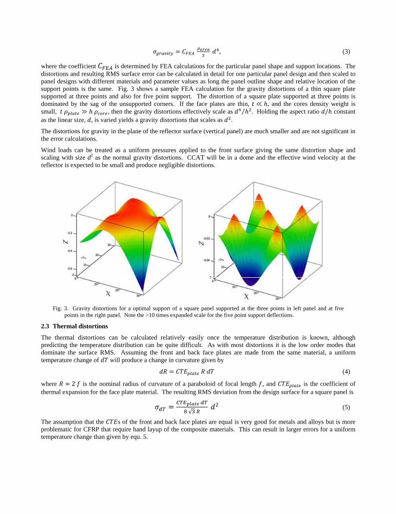
where the coefficient is determined by FEA calculations for the particular panel shape and support locations. The distortions and resulting RMS surface error can be calculated in detail for one particular panel design and then scaled to panel designs with different materials and parameter values as long the panel outline shape and relative location of the support points is the same. Fig. 3 shows a sample FEA calculation for the gravity distortions of a thin square plate supported at three points and also for five point support. The distortion of a square plate supported at three points is dominated by the sag of the unsupported corners. If the face plates are thin, , and the cores density weight is small, , then the gravity distortions effectively scale as ⁄ . Holding the aspect ratio / constant as the linear size, , is varied yields a gravity distortions that scales as .
The distortions for gravity in the plane of the reflector surface (vertical panel) are much smaller and are not significant in the error calculations.
Wind loads can be treated as a uniform pressures applied to the front surface giving the same distortion shape and scaling with size d2 as the normal gravity distortions. CCAT will be in a dome and the effective wind velocity at the reflector is expected to be small and produce negligible distortions.
Fig. 3. Gravity distortions for a optimal support of a square panel supported at the three points in left panel and at five
points in the right panel. Note the >10 times expanded scale for the five point support deflections.
2.3 Thermal distortions
The thermal distortions can be calculated relatively easily once the temperature distribution is known, although predicting the temperature distribution can be quite difficult. As with most distortions it is the low order modes that dominate the surface RMS. Assuming the front and back face plates are made from the same material, a uniform temperature change of will produce a change in curvature given by
(4)
where 2 is the nominal radius of curvature of a paraboloid of focal length , and is the coefficient of thermal expansion for the face plate material. The resulting RMS deviation from the design surface for a square panel is
√ (5)
The assumption that the s of the front and back face plates are equal is very good for metals and alloys but is more problematic for CFRP that require hand layup of the composite materials. This can result in larger errors for a uniform temperature change than given by equ. 5.

There is an additional error contribution for a uniform temperature change of a panel from the thermal expansion of the core material if the edge sensors are not mounted on the front face plates. If they are mounted on the back face plate then the front surface of the panel will move by
(6)
relative to the surface defined by the sensors and surface control system. For the purposes of calculating this contribution to the HWFE it is the change in temperature from panel to panel that is important. If there are lateral temperature gradients across an individual panel then the above formula applies even if the sensors are mounted on the reflector surface.
The most troublesome thermal distortion mode is a simple front to back temperature gradient, ΔT , which results in “thermal cupping”. As the front plate shrinks relative to the back plate, the panel’s radius of curvature changes by
Δ / (7)
A temperature gradient through the panel requires a thermal flux through the panel. One difficult to avoid source of a thermal flux is radiant cooling of the front reflecting surface to the cold night sky. This thermal flux is dependent upon the surface emissivity but is independent of the panel thickness and core material. The front to back temperature difference produced by this flux, , is
Δ / , (8)
where is the thermal conductivity of the core. Putting this gradient into equ. 7 gives
/ (9)
independent of the panel thickness. There are other sources of thermal gradients such as differences between the air temperature in front of the panels and that behind the panels. One method to minimize the effects of the radiant cooling to the sky is to put foam insulation on the backside of the panels to reduce the net thermal flux. The radiant cooling flux is still present but the whole panel cools slightly so that there is a nearly equal and opposite flux from the air in front of the panel to the front surface leaving a much smaller net flux through the panel. This technique has worked very well on the Caltech Submillimeter Observatory telescope.
The thermal cupping can have a very adverse effect on the telescope surface and be much larger than its contribution to the surface RMS of the individual panels. The basic idea of using edge sensors on the panels to measure the distortions and maintain the surface figure works by moving the panels in piston, tip and tilt to maintain surface continuity and slope between neighboring panels. If all of the panels experience the same change in curvature from thermal cupping then the new surface will still closely approximate a paraboloid with a different focal length. Refocusing the secondary can correct much of the wave front error at the expense of a slight degradation of the field of view. Even more troubling is when the thermal cupping changes systematically across the surface say from the bottom edge to top edge because of vertical thermal gradients in the dome. Fig. 4 shows an example of how a simple surface control system for a 36 panel telescope would respond in this case. The control system produces a nice continuous and smooth surface but the net surface error with the control system on is ~10 times larger than the errors from the cupping of the individual panels. Clearly this mode of distortion and control system response needs to be minimized.
2.4 Thermal environment
Calculating or even measuring the thermal environment of the reflector panels on a large telescope is difficult at best. A telescope out in the open operating day and night will experience a wide range of thermal loads. Fortunately CCAT will operate in a dome and mostly at night. A simple thermal model has been put together to estimate the thermal gradients in the CCAT panels. This model includes radiation to the sky, heat transfer to the front surface air, internal conductive and radiant heat transfer from the front to back panel faces, conduction through the foam on the back of the panel, heat transfer to the dome air behind the panels and radiant heat transfer to the inside of the dome. The parameters that go into the thermal model and typical values are given in table 3. Applying this model to a wide variety of panel configurations results in front to back temperature gradients in the range 0.1 to 0.5 K.

Fig. 4. Control system response to a gradient in the amount of thermal cupping across the aperture of a telescope. The plot
on the left shows the surface errors before turning the control system on and the plot on the right shows the surface with the control system on.
Table 2. Thermal environment parameters.
thermal surroundingsaverage segment temperature [K] 273temp. difference BUS to dome air [K] 5foam thickness [m] 0.05foam surface emissivity 1.00effective air boundary thickness back [m] 0.05thermal emissivity of back of segment 0.07thermal emissivity of front of segment 0.04effective air boundary thickness front [m] 0.05fraction of cold sky seen by segments 0.50
2.5 Fabrication errors
The panel fabrication errors are an obvious contribution to the HWFE but it is difficult to arrive at reliable values for these errors without going through the production of several full sized prototype panels, and the errors will depend on the method for building the panels. The approach used here is to enter the expected fabrication error for a d = 1 m panel and then scale this to different sized panels. There is no rigorously defendable scaling law for fabrication errors, especially for panels replicated off a mold. The effort and precision that goes into the fabrication of any particular panel will vary greatly from project to project and even when the same technique is used it is difficult to arrive at a scaling law. However, you can look at the sources of error in manufacturing a panel, including fabrication of a mold if that is required, and they are essentially the same as for the panels themselves, i.e. gravity and thermal loads. From the above panel analysis it is seen that these errors typically scale as d2. There is also the stress relaxation and rebound effects which occur in both direct machined and replicated panels especially for freestanding panels that use kinematic three point support. Much effort is put into minimizing these effects but they are always present at some level. The most difficult modes are cupping and twist which will scale at least as fast as d2 but could scale as d4. Unlike optical telescopes it is assumed that the budget for radio telescopes is not large enough to allow for reworking, polishing or tuning the panels after fabrication. In this paper we assume that the fabrication errors will scale as d2.
Best manufacturing practice can usually achieve on the order of 1:105 precision over the volume within a single machine. Modern large precision machines have a working volume of ~1 m3. This would yield of ~10 microns RMS on

a 1 m panel. With great attention to details like thermal control of the manufacturing environment and using the best factory metrology methods you might hope to achieve 1:106 or 1 micron RMS on a 1 m panel. Although the techniques are quite different for machined parts and replication from polished molds the same metrology and precision issues apply. So depending upon your budget and manufacturing process the fabrication error for a 1 m panel will be in the range of 1 to 10 microns.
2.6 Error budget
The error terms discussed above are the basis for calculating the panel error budget. Table 3 shows the calculated error budget for a set of panel designs. The design parameters that are common to all of the design cases are listed on the left side of the table. The values used are sensible but not optimized. Note that an optimistic manufacturing error of only 1 micron RMS is assumed for a 1 m diagonal panel. Design cases 1 and 3 have CFRP cores which have poor thermal conductivity. This leads to large front to back thermal gradients. Using low CTE (coefficient of thermal expansion) CFRP minimizes the thermal cupping while case 1 with high strength CFRP has very large thermal cupping. Using Al honeycomb core material gives much higher thermal conductivity and significantly improves the performance despite the poor CTE as seen in case 2. The other critical design parameter is the linear size, d, of the panel. The dependence of the manufacturing errors and the thermal cupping are the dominant sources of panel error as seen in cases 6, 7 and 8. These errors effectively limit the size of panels that will meet the CCAT specifications to the range from 1 to 1.5 m diagonal length.
Table 3. Sample panel error budgets for a set of monolithic panel designs. The panel configuration parameters presented on the left table apply to all of the designs in the error budget on the right. The only change in the designs is the face plate material and the diagonal length. The design parameters for the CSO in the right column have been modified to correspond to the detailed design of it’s panels.
The table also shows terms for the effect of panel errors on the primary surface maintenance system. These errors will depend upon the surface tiling, sensors used and control system design but the values in the budget are indicative of their potential contribution to the total system error budget. The edge deflection error arise from the wind, temperature change and lateral temperature panel errors. It is also assumed that the gravity distortions are predictable with an accuracy of 10% percent and compensated in the control system. The edge deflection errors will effectively put errors into the control system. If these errors correspond to high order HWFE distortion modes, then the error multiplication factor for the control system will be near unity [5]. The thermal cupping errors are likely to have large scale structure and the distortions modes like those displayed in Fig. 4 where the curvature effectively extrapolates to half of the telescope diameter. These errors will dominate the surface error unless techniques are used to mitigate this effect.
The last column of Table 3 uses parameters appropriate for the panels on the Caltech Submillimeter Observatory, CSO, telescope, mainly thinner insulation on the back of the panels and higher surface emissivities. This is a 10.4 m diameter telescope operating in a dome on Mauna Kea, HI. It is encouraging that the resulting calculations, ignoring the primary figure maintenance terms, are consistent with the actual performance and in particular the predicted front to back
Monolithic Panel 25m Diameter Telescopeenvironment parameters design case 1 2 3 4 5 6 7 8 CSOwind [m/s] 5.0 monolithic panel designwind pressure [kgf/m^2] 1.6 face plate material CFRPH CFRPH CFRPL Ni ULE CFRPL CFRPL CFRPL AlTemp. change [K] 1.0 core material CFRPH Al CFRPL Al Al Al Al Al Allateral Temp RMS across 1m [K] 0.5 telescope configurationpanel design panel size, diagonal [m] 1.41 1.41 1.41 1.41 1.41 1.41 2.12 2.83 1.41core filling factor 0.012 panel thickness [mm] 80.60 80.60 80.60 80.60 80.60 80.60 120.91 161.20 80.60plate normalized thickness t/length 0.0006 number of panels 491 491 491 491 491 491 218 123 85core normalized thickness h/length 0.057 areal density [kg/m^2] 4.85 5.73 4.85 16.42 6.43 5.73 8.59 11.45 7.30manufact RMS for a 1m panel [micron] 1.0 back-front temp. diff. [K] 0.60 0.12 0.60 0.12 0.12 0.12 0.17 0.21 0.32aging RMS for 1m [micron] 0.1 panel errors [microns]
gravity 0.07 0.08 0.17 0.26 0.35 0.20 0.44 0.78 0.36wind 0.02 0.02 0.05 0.03 0.09 0.06 0.08 0.12 0.08temperature change [K] 0.01 0.01 0.00 0.08 0.00 0.00 0.00 0.00 0.15thermal cupping 0.54 0.11 0.05 1.42 0.00 0.01 0.02 0.04 6.53lateral Trms 0.02 0.54 0.00 0.54 0.54 0.54 1.00 3.08 1.09manufacturing errors 2.00 2.00 2.00 2.00 2.00 2.00 4.50 8.00 4.00aging 0.25 0.25 0.25 0.25 0.25 0.25 0.56 1.00 0.25net panel error [microns] 2.09 2.09 2.02 2.54 2.12 2.10 4.67 8.66 7.75primary figure maintenance 0.00 0.00 0.00 0.00 0.00 0.00 0.00 0.00 0.00edge deflection error 0.03 0.54 0.06 0.55 0.55 0.55 1.00 3.08 1.10therm. cup. extrap. to half dia. 42.31 8.56 4.23 111.27 0.26 0.86 0.79 0.73 88.27total surface error [microns] 42.36 8.83 4.69 111.30 2.20 2.33 4.84 9.22 88.61

temperature gradient is close to the ~0.3 K measured on the telescope and shown in the plots in Fig. 5. Significantly the largest measured gradients varied nearly a factor of two across the surface and with time which would introduce large errors of the form shown in Fig. 4 if a control system based only an edge sensor were used.
Fig. 5. Plot of the back to front temperature differences for three panels on the CSO telescope during a night of
observations along with the dome air temperature and the zenith angle.
3. COMPOUND PANELS As seen from the above discussion, there is a limit to the viable size for monolithic panels. Small panels lead to having a larger number of actuators, more degrees of freedom to be controlled and more nodes in the reflector support structure. Larger panels can be built using a compound panel where several reflective tiles are mounted on sub-frame. The sub-frame provides the structural strength and stability while the tiles provide the accurate reflecting surface. The tiles are attached to the sub-frame with manual adjusters. A measuring machine would be used to manually set the correct surface figure in the factory. Separating these functions gives many more design options at the cost of more complexity in the panels.
3.1 Sub-frame construction
Two possible sub-frame construction methods are shown in Fig. 6. The compound panel on the left is constructed from CFRP face plates and an Aluminum honeycomb core, much like a monolithic panel would be made. The compound panel on the right uses all CFRP box truss construction. This allows a lot of possibilities for optimizing the strength to weight ratio for the sub-frame. Even more complicated bridge truss structures can be used, but this complexity is probably not necessary. The sub-frame would be kinematically attached to the reflector support structure with three computer controlled actuators. It is anticipated that the gravity deflections of the compound panel will be a small component in the error budget and a better job of optimizing the support node and actuator locations can be done than would be possible for monolithic panels in which the gravity deflections can be a significant part of the error budget. The sub-frame does not require precision fabrication and standard flat CFRP plates formed in a hot press or other standard method and cut to shape using water-jet pattern cutting can be used. The whole sub-frame can also be dip coated and heat cured to seal the CFRP and minimize the aging effects.
The optimal sub-frame size will depend upon the construction technique and other considerations. Keystone shaped panels roughly 2 m on a side are a reasonable size. Only ~120 panels would be required for the 25 m diameter CCAT

telescope. This size fits inside large but common commercial precision measurement machines. This size also can be shipped inside standard shipping containers.
Fig. 6. Compound panel concept showing two different types of sub-frames. Each sub-frame holds four tiles and each tile
is attached to the sub-frame by five adjusters. The foam insulation surrounding the sub-frames is not shown for clarity.
3.2 Thermal stability
An important aspect to the compound panels is that the sub-frame can be surrounded by foam insulation to greatly reduce the thermal gradients and increase the stability of the sub-frames. For clarity the insulation is not shown in Fig. 6. The detrimental front to back thermal gradients should be much less than ~0.1 K and CFRP layups optimized for strength and cost can be used.
3.3 Reflector tiles
The reflector tiles are not actively controlled and can be supported at more than three points. Tile size and number of support points are design parameters that can be used to trade off complexity, cost and surface errors. The design shown in fig. 5 has four tiles mounted on each sub-frame and each tile supported at five points. The five point support reduces the gravity deflections of the tile by more than a factor of ten relative to the same size tile optimally mounted on three points as demonstrated in Fig.3. Also the troublesome low order fabrication errors can be tuned out during the factory tile setting procedure. In the error budget calculations it is conservatively assumed that he errors for a tile supported on five points are equivalent to a tile with half of the linear size supported at three points. The formulas described above for monolithic panel errors are applied to the tiles using this reduced effective size.
The resulting large reduction in the tile errors relative to large monolithic panels means that many more tile configuration and fabrication options become viable, ranging from CFRP replicated tiles to tiles machined from billets of Aluminum. The most accurate panels fabricated for existing sub-millimeter radio telescopes come close to meeting the CCAT requirements if tiles smaller than 1 m x 1 m are used. Thus the tiles should not require an extensive research or development and present a low risk to the project.
3.4 Sensor configuration
The sensors should be carefully attached to the most stable part of the panel, which in the case of compound panels is the sub-frame. There are many options in how you build the sub-frames and attach the sensors. Figure 6 shows CFRP arms extending from one sub-frame to overlap with the neighboring sub-frame with the intention that commercial gap sensors would be used to measure the gap between the arm and the neighboring sub-frame. These sensors are not constrained to fit in the small space between the reflecting tiles and a variety of off-the-shelf sensors ranging from capacitive sensors, LVDTs, or simple reflective light beam sensors could be used. The sub-frame can also support many other types of metrology without affecting the design and fabrication of the tiles.
This sensor configuration in Fig. 6 is similar to the paddle sensors used for the Keck segments [4]. The two sensors on each common edge are sensitive to both the continuity between the panels and the dihedral angle between them using a single type of sensor. The ability to measure changes in the dihedral angle is important for controlling the low order distortion modes and the arms on the sub-frame can be lengthened to increase the dihedral angle sensitivity [5].

3.5 Extra error contributions
There are additional error sources that occur for compound panels that are not present for monolithic panels. The “edge” sensors are mounted on the stable sub-frame and are not directly attached to the front reflecting surface. Thus the thermal expansion and distortions of the tile adjusters and tile cores must be added to the surface error budget. Fortunately the tile adjusters are short and can be made from low CTE Invar. Since the tiles are mounted at five points the gravity distortions will be small even for relatively thin tiles and the thermal expansion of the cores will not be significant.
The tiles will need to be set and this will introduce an additional error term. A full up test of the panel measuring and tile adjustment procedure is required to accurately determine this error component but it is anticipated that with care the errors for a single adjuster can be kept below 0.2 microns and the net accumulative error should scale no worse than as a random walk among the adjuster, i.e. as the square root of the number of adjusters. An iterative adjustment procedure can further reduce these tile setting errors.
The sub-frame construction is similar to the generic panel model discussed in section 2 above and the same methods can be used for calculating the sub-frame errors. The principal difference is the thermal environment, particularly the surface emissivity, foam insulation on the front and back surfaces of the sub-frame and no direct radiation to the cold sky.
There are more components and complexity in the compound panel so the aging and stress relaxation effects are likely to larger than for a monolithic panel, but the compound panel offers the potential for resetting the tiles if necessary. This would be a complex and expensive proposition but would offer a method for recovering from unlikely or unanticipated problems.
3.6 Compound panel error budget Table 4. Sample panel error budget for a set of compound panel designs. The panel configuration parameters presented on
the left table apply to all of the designs in the error budget on the right except that the last model on the right, highlighted in yellow, has had the tile and sub-frame designs optimized to minimize the areal density and errors.
Table 4 shows the calculated error budget for several design cases. Most of the design cases are for 2 m x 2 m sized sub-frames. The tile manufacturing error has been increased from the value of 1 micron for a 1 m diagonal monolithic panel
environment parameters error budgetwind [m/s] 5.0 design case 1 2 3 4 5 6 7wind pressure [kgf/m^2] 1.6 sub-frame size, diagonal [m] 2.83 2.83 2.83 2.83 4.24 2.83 2.83Temp. change [K] 1.0 number of compound panels 123 123 123 123 55 123 123lateral Temp RMS for 1m [K] 1.0 number of tiles per raft 4 4 4 4 9 4 4tile parameters tile designmanufacturing RMS for 1m [micron] 5.0 face sheet material CFRPH CFRPH CFRPH CFRPH CFRPH Ni CFRPHaging RMS for 1m [micron] 1.0 core material Al Al Al Al Al Al Aladjuster design net tile error, 5 point support 2.77 2.77 2.77 2.77 2.77 2.79 2.61material invar net tile adjuster error 2.11 2.11 2.11 2.11 2.42 2.11 2.11sub-frame design sub-frame designcore filling factor 0.0100 face sheet material CFRPH CFRPH CFRPL CFRPL CFRPL CFRPH CFRPLplate normalized thickness t/length 0.0015 core material Al CFRPH Al CFRPL CFRPL Al CFRPLcore normalized thickness h/length 0.0500 sub-frame errorsTemp. change [K] 20.0 total panel areal density [kg/m^2] 25.7 24.4 25.7 24.4 33.8 36.4 10.7segment setting RMS for 1m [micron] 1.0 dT back-front 0.06 0.19 0.06 0.19 0.19 0.06 0.19aging RMS for 1m [micron] 0.1 gravity, including tile and adj. wt. 0.36 0.34 0.90 0.85 1.76 0.51 0.83
wind 0.02 0.02 0.05 0.05 0.08 0.02 0.12temperature change 0.51 0.51 0.05 0.05 0.12 0.51 0.05thermal cupping 0.13 0.38 0.01 0.04 0.06 0.13 0.04lateral Trms 2.70 0.12 2.70 0.01 0.02 2.70 0.01aging 0.80 0.80 0.80 0.80 1.80 0.80 0.80net sub-frame error 2.89 1.09 2.95 1.17 2.52 2.91 1.16
net compound panel error 4.5 3.6 4.6 3.7 4.5 4.6 3.6primary figure maintenceedge deflection error 2.75 0.53 2.70 0.11 0.23 2.75 0.16therm. cup. extrap. to half dia. 2.45 7.45 0.24 0.75 0.51 2.45 0.76total surface error [microns] 5.8 8.3 5.3 3.8 4.5 5.9 3.6
Compound Panel 25m Diameter Telescope

in Table 3 to 5 microns for the tiles used on compound panels. A significantly larger aging term is also used. The contributions the tiles make to the compound panel error budget are consistently small and only weakly dependent on the type of tile used. The contribution of the manual tile adjusters is similar in magnitude to the tile’s contribution but is small and independent of the tile or sub-frame construction. All of the sub-frame designs are sufficient for the CCAT requirements with the exception of the high modulus CFRP construction in case 2 which has a larger front to back thermal gradient which pushes the net thermal cupping for the surface slightly above the specifications. Even case 5 for a 3 m x 3 m sub-frame easily meets the specified 7 micron RMS contribution for the panel and surface maintenance components to the HWFE. The design parameters in case 7 were adjusted to reduce the areal density and net surface error. This case shows the potential for compound panels to push beyond the CCAT requirements and still have a very light weight structure.
4. SUMMARY A method has been presented for calculating of the contributions of the reflector panels to the HWFE for a large diameter submillimeter radio telescope. The method uses a generic panel model which approximates many types of radio telescope panels and can use many different construction materials. This makes it easy to quickly evaluate numerous different panel options to determine the most viable designs that justify further detailed investigation. The model error budget includes estimates for the effect the panel errors will have on a Keck style [4, 5] surface control system.
The CCAT error budget only allocates ~7 microns to the primary surface component of the HWFE. A very careful system design including the surface control system, sensors and the details of the panels will be required to develop a system the will meet these challenging specifications. The stability of the panels is paramount when the control system is based on using “edge” sensors mounted on the panels for the surface distortion measurement and feedback into the control algorithm. The error budgets for several sample designs using monolithic panels show that the d2 scaling of the fabrication and thermal cupping errors effectively limit the size of panels that will meet the CCAT HWFE to ~1 m x 1 m even when optimistic assumptions for the fabrication errors and the thermal environment are used.
A compound panel concept is explored as an alternative to monolithic panels. This concept separates the functions of providing an accurate high reflectivity surface from providing the mechanical support and stability. Light weight accurate reflecting tiles are mounted onto stiff and thermally stable sub-frames. The tiles are manually adjusted to the desired figure in the factory. This concept increases the complexity of the panels but overcomes many of the difficulties and risks associated with monolithic panels. It also allows the fabrication of panels as large as 2 m x 2 m and still easily meets the CCAT specifications. The increased size reduces the number of computer controlled actuators and the node density in the reflector support structure. This should offer a robust solution to the problem of fabricating high accuracy panels for large sub-millimeter telescopes with active surface control.
REFERENCES [1] Ruze, J., "Antenna tolerance theory - a review," Proc. IEEE, 54, 633-640 (1966). [2] Von Hoerner, S, "Design of large steerable antennas," The Astrophysical Journal, 72, 35-47 (1967). [3] Sebring, T. A., Radford, S., Giovanelli, R., Zmuidzinas, J., Herter, T., “The Cornell Caltech Atacama Telescope
Status and Technical Progress,” Proc. SPIE, Ground-based and Airborne Telescopes Conference (2008). [4] Troy, M., Chanan, G., Sirko, E. and Leffert, E., "Residual misalignments of the Keck Telescope primary mirror
segments: classification of modes and implications for adaptive optics," Proc. SPIE Int. Soc. Opt. Eng. 3352, 307 (1998).
[5] MacDonald, D., Woody, D., Bradford, M., Chamberlin, R., Dragovan, M., Goldsmith, P., Radford, S.,Sebring, T., and Zmuidzinas, J., "Cornell Caltech Atacama Telescope Primary Mirror Surface Sensing and Controllability," Proc. SPIE, Ground-based and Airborne Telescopes Conference (2008).
[6] G. Cortes-Medellin & P.F. Goldsmith "Analysis of Active Surface Reflector Antennas for a large millimeter Wave Radio Telescope," IEEE Trans. Antennas Propagation, vol. 42, pp. 176-183 (1994).
[7] Nelson, J.R., Lubliner, J. and Mast, T.S., "Telescope Mirror Supports - Plate Deflections On Point Supports," Proc. SPIE 332, pp. 212-228 (1982).