particle detectors - connecting repositories · particle detectors k. kleinknecht ... the number of...
TRANSCRIPT

PARTICLE DETECTORS
K. KLEINKNECHT
Institutfür Physikder UniversitdtDortmund, Dortmund,Gennany
NORTH-HOLLAND PUBLISHING COMPANY — AMSTERDAM

PHYSICS REPORTS(Review Sectionof PhysicsLetters)84, No. 2 (1982)85—16 1. North-Holland Publishing Company
PARTICLE DETECTORS
K. KLEINKNECHTInstitut fir Physikder (JnivergitdtDortmund,Dortmund, Germany
Received 29 December1981
Contents:
1. Introduction 87 4. Identification methods 1192. Position measurement 87 4.1. Time-of-flight 119
2.1. Physical processes for detection 87 4.2. Cherenkov counters 1192.2. Proportional chambers 89 4.3. Transitionradiationdetectors 1262.3. Planar drift chambers 94 4.4. Multiple ionization measurement 1302.4. Cylindrical wire chambers 96 4.5. Comparison of identification methods 134
2.5. Pictorial drift chambers 98 5. Energy measurement 1352.6. Time projection chamber 101 5.1. Electron—photon shower counters 1352.7. Bubble chambers 103 5.2. Hadron calorimeters 1422.8. Streamerchambers 104 5.3. Monitoring of calorimeters 1462.9. Flashand spark chambers 108 6. Momentummeasurement 1482.10.Comparisonof positiondetectors 109 6.1. Magnet shapesfor fixed target experiments 148
3. Timemeasurement 110 6.2. Magnet shapesfor storagering experiments 1503.1. Photomultiplier 110 6.3. Centraltrackingdetectors 1513.2. Scintlllators 111 7. Realizationof detectorssystems 1533.3. Light collection 114 7.1. Ahadronbeamdetector 1533.4. Planarsparkcounters 117 7.2. Aneutrinodetector 154
7.3. A protonstoragering detector 1557.4. An electron—positron storage ring detector 158
8. Conclusion 158
References 158
Abstract:
Theprinciplesof instrumentsusedfor detectingand identifyinghigh energyparticlesare reviewed.Recentprogressin tech-niquesand materialsis included.A few realizationsof detectorsystemsaredescribed.
Single ordersfor thisissue
PHYSICS REPORTS(Review Sectionof PhysicsLetters)84, No.2(1982)85—161.
Copiesof this issuemaybeobtainedat thepricegivenbelow.All ordersshouldbesent directlyto thePublisher.Ordersmustbeaccompaniedby check.
Single issuepriceDfl. 40.00,postageincluded.
0 370-1573/© 1982North-HollandPublishingCompany Open access under CC BY-NC-ND license.

K. Kleinknecht,Particledetectors 87
1. Introduction
Progress inexperimentalparticle physics has alwaysbeenclosely linked to improvementsinaccelerator anddetectortechnology.The searchfor small orpoint-like constituentsof matterre-quired the study of scatteringandannihilationprocessesat ever largercenter-of-massenergies.This was achievedeitherby largefixed-target accelerators,like the 400GeV Proton Synchrotronsat CERN andFermilaband the 30 GeV electronLINAC at SLAC, or by storagerings both forprotons(CERN TSR) andelectron—positronpairs(SPEARandPEPat SLAC, DORIS andPETRAat DESY, CESRat Cornell). Thehighestc.m. energyavailablenow is 540GeV providedby theantiproton—proton colliderat CERN. Progress inacceleratortechnologyincludesthe inventionof stochasticandelectroncooling of antiprotonbeamsandthe developmentof superconductingpulseddipolemagnetsfor the 800GeV Tevatronat Fermilab.
Experimentsare based onthe ability of the researcherto detectparticles producedby theseacceleratorsor storagerings. Thedetectingequipmenthasundergonethreemajordevelopmentsduring the past ten years: the size of experimentshas beenincreasing;for fixed-target experi-ments, this is a naturalconsequenceof the largermomentaof particles involved and the corre-spondinglylarger leverarmsfor magneticanalysisrequired.Also, larger targetmasseswereneededfor reactions withsmall cross-section,as in neutrinophysics.For storageringdetectors,the largesize is dictatedby the necessityto covermostof the 47r solid anglearoundthe interactionpoint.The seconddevelopmentconcernsthe speedof dataacquisition:while pulseddevices likebubbleor sparkchamberswere limited to 1 —10 recordedevents peraccelerator pulse,the inventionofproportionalanddrift chambershas increasedthis rateby a factor of 100 enablingexperimentswith 108 recordedevents.In parallelwith this goesthethird evolution:theincrease incomplexityof the detectors.The numberof independentanaloginformations froma largeexperimentcanreach 1 o~,andafterdigitization this yields upto 1 0~bits of informationfor oneeventfrom sucha detector.Experimentsof this type havebecomepossiblebecausethe reliability of the equip-ment has increasedconsiderably duringthis time and becausefaston-line computersenableper-manentcontrol and monitoringof the detector.
In spiteof the complexityof largeexperiments,the basicprinciplesof detectorsaresimple. Inthis article, I go through theseprinciples andsomeof the newerdevelopments,following the listof physical quantitiesmeasuredby the detector:position, time, mass,energyandmomentum.
2. Positionmeasurement
2.1. Physicalprocessesfor detection
The physicalprocesseswhich enableus to detectparticlesaredifferent for neutral andchargedparticles.Photonscan interactby photoelectricor Comptoneffect or by pair creation,wherethelatter processdominatesat energies above 100MeV. The resultingelectronsandpositronscan bedetectedby their electromagneticinteraction.Neutronsof high energywill producea showerofhadronswhen colliding with detectormaterial, thusenablingthe detectionof chargedsecond-aries.Neutrinos interactby weakinteractionconservinglepton number,producinghadronsandachargedor neutral lepton.

88 K. Kleinknecht, Particle detectors
In contrastto theseneutralparticles,charged particlescan bedetecteddirectlyby their electro-magnetic interactionwith the atomic electronsof the detectormaterial.In thesecollisions, theenergyloss of a heavychargedparticlewith massm > me by ionization is given by the Bethe—Bloch-formula[BE 30, BE 32, BE 33, ST 71]:
—dE/dx= (47rr~mec2NoZz2/Af32)[ln(2mec2132/((l— 132)1)) 1321
wherex is the thicknessof material traversedin g cm2, N0 is Avogrado’snumber,Z andA are
atomic andmassnumbersof thematerial,zeandv 13c the chargeandvelocity of themoving par-ticle, me the electronmass,re = 2.8 fm the classicalelectronradiusandIan effectiveatomicioni-zation potentialrangingfrom 13.5 eV in hydrogento 1 keV in lead.The dependenceof this energyloss on particlevelocity is characterizedby the 1/132 variation at low energies,by a minimum at
= p/mc 4 and finally at high energies bythe relativistic rise by afactorwhich, for gases,isaround 1.5. Fig. 1 showsthisbehaviourasmeasured[LE 78a] in an argon—methanemixture.Theminimumvalueof the energyloss aroundfry = 4 is 1.5 MeV/(gcm—
2) for iron and1.8 MeV/(gcm—2)for carbon.
The energyloss by ionization is distributedstatisticallyaroundthe meanloss describedby theBethe—Bloch-formula,the distributionbeingasymmetricwith a tail [LA 44] at high lossesdueto6 ray productionand distantcollisions.
Thecalculationof theenergylossdistributionwasfirst doneby Landau[LA 44] andSternheimer[ST 52] assumingthat the Rutherfordterm in the cross-sectionis the only sourceof the fluctua-tions and that its behaviourin the region of binding energiesis describedby a mean ionizationpotential. Fig. 2 showsthat this model reproducespoorly themeasured[HA 73] energyloss dis-tribution for thin (1.5 cm) gaslayers,but thatmorerefinedcalculationsincluding the shellstruc-
1.7Argon — — —— ——
- 6cm
1 10 100 1000 10000
P//i-c
Fig. 1. Ionization energyloss inargonatatmospheric pressurerelativeto valueatj3.y = p/cm 4. Points from [LE 78a] in argon/5%CH
4 dashedline: calculation of [ST 52]; dash—dotline: [ER 77]; solid line: photo absorptionionization model [CO 75,CO 76, AL 80].

K. Kleinknecht,Particledetectors 89
jf~\ 3 GeV/c r~ 3 6eV/c ej] \ 1,5cm 1.5 cm
I I
dN
/ pI It Ill “In - ~Ip ~.:jI lip
[~I L\\ r11 \ \J/p \ \
Il ri \~ . I -/1 I
_Jl I I - .1 I I I~ —
012345678 01 2345678L~KeV ~KeV
Fig. 2. Ionization energyloss distributionfor pions andelectronsin 1.5 cmof argon: 5% CH~at atmospheric pressure.Dataof[HA 73]. Dashedcurveof [LA 44, MA 69], dottedcurveof [LA 44, BL 50], solid curveof [AL 80].
ture of the atoms(Photo Absorption IonizationModel, PAl [CO75, CO 76, AL 80]) give a satis-factory descriptionof the data.The relativistic riseof the energyloss as measuredin fig. I is alsoreproducedwell by thesemodels,while formercalculationsgave a risewhich was too large by10—15%.
The averageenergy neededfor creating an electron—ion pairis fairly similar in differentgases,viz. 40 eV/pairin helium and26 eV/pairin argon, while itis muchsmallerin solids,e.g. 3 eV/pairfor Si, suchthat for solids the numberof pairs is larger andthe statisticalfluctuationsin energyloss are smaller. However,the technical problems withthe productionof large volumesof puri-fied semiconductorshavelimited the use of Si- andGe-countersto low-energy highresolutionyspectroscopy.Fordetectionof charged particlesin large areadetectorswe areleft with ionizationin gases,mainly noble gases,and in liquid or solid scintillatorsconvertingthe ionization energyloss into visible light.
2.2. Proportional chambers
Proportionaltubeshadbeenused since along time. A cylindrical tube(radiusra) on negativepotential and acentralwire (radius r1) on positivepotential createan electric field of the form
E(r) = V0/(r ln(ra/rj))
which reaches10~—1 0~V/cm nearthe anodewire. An electron liberatedin an ionization processgainsthe kinetic energyz~T betweentwo collisionsat radial distancesr1 andr2

90 K. Kleinknecht, Particledetectors
~ewIres
0800.85
0.90
Fig. 3. Field configuration in a proportionalchamber;field andequipotentiallines are drawnECH 70bj.
~T-efE(r)dr,
and if L~Texceedsthe ionization energyof thegasatoms,asecondary ionizationcantakeplace.A chain of such processes leadsto an avalancheof secondaryelectronsandions. The numberofsecondaryelectronsper primary electron (gasamplification a) reaches 104_106in the propor-tional region,wherea is independentof the numberof primaryelectrons.
The field configurationin a proportionalchamber withmany anodewires in aplanebetweentwo cathodeplanesis shownin fig. 3. Thediscoveryof Charpaket al. [CH 681 wasthat thesesep-arateanodewires act as independentdetectors.The capacitivecoupling of negative pulsesfrom

K. Kleinknecht,Particledetectors 91
I ++ I+ /
\++ I
Fig. 4. Shapeof theionizationavalanchein a highelectricfield [LO 61].
onewire to thenext is negligible comparedto the positivepulse onthe neighbourwires inducedby the moving avalanche.The maincontributiondoesnot comefrom the fast-movingelectronsbut from the much (1000times)slower ions inthe drop-shapedavalanche(fig. 4). Thetime struc-ture of the negative pulseinducedon the anodewire by the avalanches hasbeenclarified subse-quently [Fl 75]. It consistsof severalpulsesinducedby differentavalanchescreatedby differentprimary ionization electronsdrifting oneafter anotherinto the high field regionnearthe anodewire. These pulses havetypically a rise-timeof 0.1 nsfrom the electronpart anda decaytime of30 nsfrom the ion part of the avalanche.Fig. 5 shows anoscilloscopepicturewith atime resolu-tion sufficient to resolvetheseseparatepulses,which in normal applicationsare integratedintoonepulse by sloweramplifiers.
As a practicalexamplefor operatingproportionalchambersystems,oneof the first spectrome-terswith largechambers[SC 711 used a wiredistanceof 2 mm,gold-platedTungstenwiresof 20~tm, a gapbetweensignal wires and cathodeplaneof 6 mm andan argon—isobutanegasmixture.The amplifiers [CU 71], based onMECL 1035 chips, hada thresholdof 200pV on 2k~2andaneffective resolvingtime of 30 ns.Thedetectionefficiencyfor this system, shownin fig. 6, allowsoperatingat full efficiency at 4.3 kV with a 40 ns sensitivetime, i.e. the gatefor thewire signalswas openedby anexternaltrigger forthistime interval.The spaceresolution for this wire distanceis a ‘-~ 0.7 mm.
One of the problemsencounteredin largechambersis the mechanicalinstability of the signalwiresdueto the electrostaticforcebetweenwires. It can becalculated[TR 691 that the systemisstableif the wire tensionT exceedsa valuegiven by the wire geometry
T> (Vl/2 ira)24ire0
where V is the potentialdifferencebetweenanodeandcathode,1 is the lengthof thesignalwire,anda is the gap betweenwire and cathodeplane.For the exampleabove,with a wire tensionof50 p, the wires are stablefor 1� 60 cm. This means thatfor larger chambersthe wires haveto besupportedevery 60 cm bysupportwires threadedacross, or byother methods.An inefficiency

92 K. Kleinknecht, Particle detectors
b)
avalanche.
Fig. 5. (a) Oscilloscope display of proportional chamber pulse showing separate avalanches. (b) Pulse shape as simulated by com- puter [FI 751.
of 10% in a region of 5 mm width around the support wire is a consequence of some of these schemes [KL 701.
An enormous increase in spatial resolution of proportional chambers can be achieved by using the information from pulses induced on the cathode plane [RA 74, CH 78aI. For this purpose, at least one of the cathode planes is made of strips perpendicular to the direction of anode wires (see fig. 7). The pulses induced by the avalanche on the individual strips vary with the distance of the strip from the avalanche, and the center of gravity of the integrated pulse heights is a measure of the avalanche position. Fig. 8 demonstrates the precision which can be obtained with this center-of-gravity method. A soft X-ray produces ionization at three positions separated by 200

K. Kleinknecht,Particledetectors 93
— I I I I
1.0 - ~__~—_:-—••----—•--——1--——•-—-—•—•——••---=.:~—.-—•--——•-—--.’———•—..—.—..—. 1.0
...— ...... —.—.— ..—,‘ , .—.. —..—.—
, / ,. .,.
/ ,/ / .,I, ./
I, / /
1/ ,i .. .,
7, / // ,/ / / / 40 nsec gate
/ I ? / ,~ — — — — 35 nsec gate~0.5 - / / / / . 30 nsec gate - 05f / / I —. —. — 25 nsec gate
/ / / / / — —.. — 20 nsec gate
/~.i ~//1 /1
/ ,/ ~•/ /,,•, ., .,./ S., ,
I I I
3.5 4.0 4.5 5.0high voLtage (K volt)
Fig. 6. Detection efficiencyof a proportionalchamber(2 mm wire distance,2 X 6 mm gap)vs. high voltage for different gateopeningtimes [SC 71].
jim. The center ofgravity y of eachavalancheandthe integratedchargec aremeasured,and thedistribution in y showsthreepeakswith a varianceof 35 jim. Most of this resolutionerror comesfrom the range of the original photoelectron.This impressiveaccuracy,however,is achievedwitha detectorwhereboth mechanicalconstructionandelectronic pulse-heightprocessingis costly.
7/
Fig. 7. Principleof cathodereadoutfor proportionalchambers.The centerof gravityof the inducedchargeson cathodestrips(b)determinesthepositionof avalanche(a), [CH 78a].

94 K. Kleinknecht. Particle detectors
200 400 600
y c rnlCmlS)
Fig. 8. Spatial resolution of a proportional chamber exposed to a 1.4 keV X-ray beam at 3 positions, 200 w apart; plotted is total charge on cathode vs. center of gravity [ CH 78a].
2.3. Planar drift chambers
A great reduction in cost is possible by using the experimental fact [CH 70aI that the time delay between the crossing of a charged particle through a proportional chamber and the creation of a pulse on the anode wire is related to the distance between particle trajectory and anode wire. This delay was found to be of the order of 20 nsec/mm, and if this time is measured for each anode wire with an accuracy of 4 nsec, a spatial resolution of 200 pm can be obtained.
The invention of the drift chamber [CH 70a, WA 711 exploits this possibility. A scetch of the field configuration in one cell of a drift chamber is shown in fig. 9. The electrons from the prima- ry ionization process drift in a low field (1000 V/cm) region into the high field amplification re- gion around the anode wire, where avalanche formation occurs. Typical drift velocities for differ- ent gases are shown in fig. 10 for various argon-isobutane mixtures [BR 741. For some of the mixtures, the drift velocity depends only mildly on the field strength, thus enabling a linear rela- tion between distances and drift time even without constructing a perfectly constant field in the drift region. This is important because the requirement of a constant drift field necessitates the introduction of several field shaping wires per cell. An example for such a cell [MA 771 is shown in fig. 11, where the cell dimensions are 60 X 30 mm ?. The linearity between drift time and dis- tance for this chamber is shown in fig. 12.
NEG.%i%TIAL NEG.ENTlAL
Fig. 9. Equipotential lines in a drift chamber cell.

K. Kleinknecht,Particledetectors 95
I I I I I I j
Drift velocity
60-
4O~ Isobutone
• Ar 86.5 13.520 - o Ar 81 19
x4r75 25- +Ar70 30
£ Ar 69 ~ 31
0 l~~I62 I” I ~8 I
o 400 800 200 600 2000 2400
Drift field [V/Cm]
Fig. 10. Drift velocitiesin argon—isobutanemixtures [BR 74].
/ / z, GROUND / S.,. ‘1 .
E
+1 kV +1.5kV +2kV 4-1.5kV +1kv
p —
0SW.4O~im POT.W.~0
+3.7kV 200p.tm
15mm~5mm~5m~5mm~ 30mm —2k
S GROUND
Fig. 11. Cell structureof largeareadrift chamber[MA 77].

96 K. Kleinknecht,Particledetectors
I I I I I
600 i~sec
400
GAP N21 ~2O4±3nsec/Cm
200
2O ~Oi~ 20_O~tance
Fig. 12. Linearrelationbetweendrift time andposition [MA 77].
2.4. Cylindrical wirechambers
For storagering detectors,cylindrical geometriesmatched to solenoidal magneticfields (Br= Bc1, = 0, Bz ~ 0) havebeenwidely used.Thesecentraldetectorsaim at the measurementof cur-vaturesandinitial directionsof tracksemergingfrom the interactionpoint (fig. 13).
The first detectorsof this kind usedcylindrical layers of proportional chambers(see2.2) orsparkchambers(see2.7) to determine the(r, ~,)trajectory of the tracks (fig. 13). The wires arestrungparallel to theB field, theE field is radial,but thedisplacementin I~of the avalanchesdueto the Lorentzforce is smalldueto the smalldrift spaceto the anodewire.
For the next generationof centraldetectors,cylindrical drift chamberswere used.Here thedetectorhas upto 20 cylindrical layersof drift cells with electricaldrift field in therIp-plane (fig.13). In order to savewires, the cells are openin the radial direction, butclosed byat least3 p0-
tential wires in the p direction. Approximately halfof the sensewiresrun exactlyparallelto theB field, the othersare inclined by a stereoangle(e.g. ±4°)relativeto this axis in order to enablereconstructionof the z positionof the tracks.
An examplefor such acentraldetectoris the TASSOchamber[BO 80]. Thedrift cell (fig. 14)is radially open, the wires are 3.5 m long. The1 5 chamberlayersextendover 85 cm radialtrack

K. Kleinknee/it,Particledetectors 97OoEIII~bHV ~. _____ HV d
Fig. 13. Different types of cylindrical wire chambers;(a) proportionalchambers,(b) cylindricaldrift chambers,(c) pictorialdriftchambers, (d) time projection chamber.
~
Potential Wires: 120pm0
t~ ~.
Sense Wire: 30pm0
Fig. 14.Geometricalarrangementof wiresin theTASSOwire detector[BO 80]. Dimensionsarein mm.

98 K. Kleinknecht,Particle detectors
S.’ —
S
—
S •. . . I
—I / ‘I. ~I F .• •I I •
: . . S •
• .
+ .-,
.‘ ~ : . ~ •• ~ • • /
•• -5-S...’.’
—
s.s c.s
Fig. 15. Hadroniceventproducedby e~ecollision at30 GeV c.m.energyin theTASSO wiredetector,seenalongthebeamdirec-tion [BO 80].
length, 6 of theseare equipped with±4°stereowires. The resolutionachievedwas� 200 jim inthe (r, Ip) planeand 3—4 mm in the z direction.Fig. 15 showsthe (r, Ip) view of a hadroniceventat 30 GeV c.m. energyrecordedby the TASSO detector.Another examplewith a closed cellstructureis the ARGUS drift chamber,shownin fig. 16 [WE 811. Herethedrift velocity is nearlyradially symmetric around the sense wire, suchthat the geometricalposition of all hits with afixed drift time is a cylinder aroundthe sensewire. This facilitatespatternrecognitionfor tracks.
2.5. Pictorialdrift chambers
This type of chamberrecordsmany (�250) three-dimensionalpointsalongthe chargedparticletrack. This measurementof true spacepointsis very instrumentalfor the reconstructionof events

K. Kleinknee/it,Particledetectors
• 0 —
H 18.80 SignaL Wire
• Potential Wires
Fig. 16. Geometryof wires, lines of constantdrift time and drift pathsin one cellof theARGUS detectorfor a 0.9T magneticfield parallelto the wires [WE 81].
fletd%\ a
Fig. 17. Cross-sectionthroughtwo segmentsof thejet chamberof the JADE detector.Length of drift pathd, Lorentz anglea[DR 80, WA 81b].

100 K. Kleinknecht,Particledetectors
with a high densityof tracks. Thefirst suchpictorial chamberwas built for the JADE detectoratPETRA [BA 79, DR 80]. Here the cylindrical volume of the trackdetectoris subdividedinto 24radial segmentsof 15°openingangle. In eachsegment(fig. 1 7), thereare 64 sense wiresparallelto the magnetic field, arrangedin 4 cells of 16 wires, i.e. a total of 1 536 sense wiresof 234 cmlength. The electric field is perpendicularto the sense wireplane,andthereforealsoto themag-netic field. Due to the longer drift length comparedto normal cylindrical drift chambers,theeffect of the Lorentz forceeu X B becomesnoticeablehere.
It leadsto a deviationof the directionof thedrift velocity UD from the directionof the electricfield E by an angleaL given approximatelyby the ratio of magneticandelectric forces,tan aL =
k(E) UDBIE [WA 81b], which in the JADE chamberatB = 0.45 T and4 atm. pressureis 18.5°.The factork(E) dependson chambergasandelectricfield [SC 80]. Due to the Lorentz force, thelines of equaldrift time in the neighbourhoodof the sense wireplanein the JADE chamberarerathercomplicated(fig. 18). Fig. 19 showsthe (r, Ip) projectionof a two-jet eventat 35 GeV c.m.energy.Up to 48 samplingspertrackarerecordedandcan be usedfor a measurementof the ioni-zationenergyloss. The z coordinatesalong the wires areobtain’edby charge division onthetwoendsof the wireswith a precisionof 1 .6 cm.
The principle of the pictorial chamberwas also used inthe AFS [CO81] andthe UA 1 [BA 80]centraldetectors(see 5.3).
~ci~
‘(V I
_a ~SOOns
t~Q~ \300os
- — ~OOns~ \2oo>_~~ /
/ ~ \\ \
/
\ —~ ---“-~~—-~~
DISTANCE FROM WIRE PLANE5 10 15 20 [mm]
I I I I
Fig. 18. Trajectoriesof drifting electrons(full lines)andlines of equaldrift times(dashed)for theJADE field configuration[DR80,WA 81b].

K. Kleinknecht,Particledetectors 101
g93 F22ILS.TPPH23O JADE A~FIStCTION ~ 15.000 GEV P~.Fl~10-‘1.532 kG OPTE 3O/O3~B0344 2154 .34 1.6 TRiGGER 0201 TIlt 12.28.18
12055‘SIUITS 0 ..—. 13L~L ~20S5~
\\\
:7//1
a
x*___vJ 3.3 3.1 ~.9
Fig. 19. Hadroniceventproducedby e~ecollisionat 30GeVc.m. energyin thejet chamberof theJADEdetector.Hits assignedto a track areshownascrosses,remaininghits axedashes[DR 80].
2.6. Timeprojectionchamber
An ingeniousway of usingthe proportionalanddrift chamberprinciplesfor the centraldetec-tor of a storagering detectorwas proposedby Nygren [NY 74, NY 81]. Fig. 20 shows a large(1 m radius,2 m length) cylindrical volume filled with argon—methaneat 10 atmospheres.Thetwo endcapsare equipped withonelayerof multiwire proportionalchambers subdividedinto sixsectors.Eachof the sectorshas 186proportionalsignalwires for multiple ionization measurementand 1 5 wires with segmentedcathodereadout(“pads”) for the spatialmeasurementof radiusrandperipheralangle~pin the cylindercoordinates(fig. 21).
Most importantlyhere,the electricdrift field (150kV/m) is parallelto themagneticfield (1.5 T)of the solenoidusedfor magneticanalysisof tracksoriginating from the collisions inthe centerof the cylinder. E X B type forcesvanish,and it is possibleto havethe ionization electronsdriftover largedistancesto the endcaps.Furthermore,the strongmagneticfield reduces considerably(factor 10) the diffusion broadeningof thetrackimage onthe endcapsof the cylinderby causinghelical movementsof the electronsaroundthe magneticfield lines.

102 K. Kleinknecht,Particledetectors
Endcap wires
Endcap wires
Negative high-voltage electrode
•-5—~
192 dEldx wires per sectorBeampipe 12 spatial wires per sector
Fig. 20. Scetch of time projection chamber [MA 78].
~DRIFT PATH~—_,.
AVALANCHE,,SIGNAL WIRE .—
±T~y4mm~pADROW~~PROJECTED ~TO
PAD PLANE
Fig. 21. Principle of cathode readoutby pads used inTPC [FA 79].

K. Kleinknee/it,Particledetectors 103
~~~ALUMINUM
PADS4 ~ANODE /
ANODE SIGNAL
DISCHARGE~CATHODE SIGNALS
PAD READOUT
Fig. 22. Section of TRIUMFTPCshowingpadsandanodewires [HA 81a].
The spatial reconstructionof the original tracksis obtainedby measuringthe two-dimensionalimageson the endcapsusingthe cathodeplane readoutandthe center-of-gravitymethod andbymeasuringthe drift time of eachtrack segment parallelto thecylinder axis. In addition, thepro-portional chambersalsomeasurethe ionizationenergyloss of thetrack,thus enablingthesepara-tion of e, iT, K andp by usingdE/dxand momentummeasurement.
Measurementson asmall testchambergavean (r, p) resolutionof less than200jim andaz res-olution along the drift path of 0.2mm [FA 79,NY 81]. Initial testson thebig chamberhavenotyet reachedthis precision.A similar andlessambitiousTPC hasbeen builtand testedatTRIUMF[HA 81a]. Hexagonalendcapswith 12 sensewiresper sectormeasurethespaceposition of tracks.At atmosphericpressurefor 80% Ar 20% CH
4andwith an electricfield of 150 V/cm the ratio ofelectric field over pressureis 0.2 V/(cm Torr), thesameas in theBerkeleyTPC.The arrangementof the cathode padreadoutshownin fig. 22 allows aprecisionof 120 jim alongthe anodewire.Preliminary initial testsgavea spatialresolutionof 600jim.
2. 7. Bubblechambers
The bubblechamber[GL 52, GL 58, FR551 consistsof a pressurevesselfilled with liquifiedgasaround the boiling temperature.By an expansion mechanism,thepressureon the liquid is re-ducedfor a short time (—ms).The liquid thenbecomesunstableagainstbubbleformation, andifduring the expansiontime achargedparticle formsa trackof ionization in the liquid, bubblefor-matjon startsat this track. After a time left for bubblegrowth (jis—ms), the trackis illuminatedand photographed throughwindowsin the vessel.With the chamberembeddedin a magneticfield

104 K. Kleinknecht,Particledetectors
Table 1Physicalpropertiesof bubblechamberliquid
Liquid Temp. Pressure Density Expansion Rad. length Absorption(K) (Bar) (g/cm
3) ratio iSV/V X0 (cm) length X (cm)
(%)4He 3.2 0.4 0.14 0.75 1027
26 4.0 0.06 0.7 1000 88730 4.5 0.14 0.6 900 403
20Ne 36 7.7 1.02 0.5 27 89131Xe 252 26 2.3 2.5 3.9C
3H8 333 21 0.43 3 110 176CF3Br 303 18 1.50 3 11 73Ar 35 25 1.0 1.0 20 116
of up to 30 kG, the trackcurvatureis usedfor momentummeasurement,andthe bubble densityb canbe usedfor a measurementof thevelocity v !3c andthusthe massof the particle [GL 581.
Chamberliquids rangefrom hydrogenas a pureprotontarget,deuteriumfor studyof interac-tion on neutrinosup to xenon for experimentswhich needa high conversionprobability for ‘yrays. Table 1 gives somepropertiesof chamberliquids [BE 77, HA 81b, WE 81b].
The bubble chamberis still uniquein its capability of analyzingcomplicatedeventswith manytracks and identifying thoseparticles. A beautiful example for such asuper-eventis showninfig. 23. However,the useof bubblechambersasisolateddetectorshasdiminishedbecause1) theycannotbe employedatstoragerings; ii) at high energy,showersarenot containedin thechambervolume anymoreexceptif thechamberis ahybrid of calorimeterandbubblechambertechniques,whichseemsto be possible usingliquid argon [HA 82] ; iii) theleverarm for momentummeasure-ment is not sufficient at high momenta.Futureusewill include small chamberswith extremelyhigh resolution,e.g. the 8 jim resolutionobtained[DY 81, MO 80] by holographicreadoutin theBIBC chamberatCERN (fig. 24). Suchchamberswill be used inconjunctionwith largespectrome-ters for momentummeasurementand identificationof reaction products(“hybrid systems”).
2.8. Streamerchambers
In a similar development streamerchambersare usedas tracksensitivetargets.In this type ofchamberelectric fields above 50kV/cm perpendicularto the trackdirectioncreatean avalanchewith gas amplification around 108 and light emission (“streamer”). The geometryof such achamberis given in fig. 25. Very shorthighvoltage pulses (few nsec) arerequiredin order to keepthe streamersshort [SC 79, RI 74].
The excellentquality of streamerchamberspresentlyin use can be seen infig. 26, a picturefrom the NA5 experimentat CERN [NA 51. The developmentofavery high resolutionstreamerchamberhasbeenpioneeredat Yale [DI 781 in order to measurethe lifetimes of charmedpar-ticles, around l0’~ sec,correspondingto a flight path of300 jim for a time dilatation factory = 10 which is typical for a particleof 30 GeV/cwith a massof 3 GeV. This chamber operatesat24 atmospheres,uses pulsesof 0.5 nsecdurationproducinga field of 330 ky/cm, anda spatialresolution of 32 jim has beenachieved [SA80]. With this techniquea goodmeasurementofcharmedparticle lifetime seemsfeasible, competitive with similar experimentsusing nuclearemulsions.

K. Kleinknee/it,Particledetectors 105
1,,I~
I~
/ ‘N.0
<~-~ A
I I> ~ 0. Q
w ~ l~g:
~ L ~ __ ~ /4~ / ~~ ‘~— \_~ - --. - - ~ I. 11 Y ~—. I a
_ ____ ___
___________ ~ ~ ~__ - -~- S ‘~•-;~~ ~L~t~—_.1..~, ,.~-... ..- - ___ _____
M , .~. - -. . .. /.~~. / ~_______ - It J f._
~ ~

106 K. Kleinknee/it,Particledetectors
Fig. 24. Holographicphotographof a 15 GeV 1r interactionin a smallfreonbubblechamberBIBC. Bubble sizeis 8 ~im[DY 81].
-~IDENc~j---1
HIGH J 500KV10 nsec
VOLTAGE A
I II’ ~ •I II~ ~
VIEW NORMAL TO E~FIELD
1~~VIEW PARALLEL TO E-FIELD
Fig. 25. Schematicview of streamer chamber[SC79].

K. Kleinknecht,Particledetectors 107
~~ ———
Fig. 26. Interaction of a 300 GeV ir in a liquid hydrogen target as seen in a streamer chamberof dimensions200 X 120 X 72 cm3
[EC 80].

108 K. Kleinknecht,Particledetectors
2.9. Flash andsparkchambers
Another gasdischargechamberis theflash chamberdevelopedby Conversietal. [CO 55,CO 78 1andbuilt in a similar wayfor the FMNN neutrinoexperimentat Fermilab[TA 78]. The chamberconsistsof an arrayof rectangulartubes madeof polypropyleneby extrusion.This arrayis placedbetweentwo metal electrodesand filled with a neon (90%)—helium(10%) mixture (fig. 27). AtriggeredHV pulse is appliedon the electrodesgeneratinga glow discharge inthosecells whereionization has beeninducedby passingparticles.This discharge can berecordedby photograph-ing or byelectronicreadout.The flashchamberreachesan efficiencyof 80%.Due to theextreme-ly low cost,large volumecalorimeterswith fine grainsamplingcan bebuilt.
The sparkchamber hasbeenused widely as a triggeredtrack detector.A set of electrodesormassiveplates is insertedin a noble gasvolume(typically He/Ne) at atmosphericpressure. Theplatesarealternatinglyconnectedto apulsedHV supply or ground.After the passageof an ioniz-ing particle, a HV pulse is triggeredvia asparkgap, causing asparkbreak-throughat theplace ofthe initial ionization but parallel to the electric field (fig. 28). For chambergasesat atmosphericpressure,the magnitudeof the pulsed electricfield hasto be 10—20 kV/cm in order to generatesparks.
The sparkposition is recorded opticallyor by magnetostriction.Here the electrodesof thechamberconsistof wire planes,andamagnetostrictivewire (madeof aCo—Ni—Fe-alloy) runningacrossthesewires picks up asignalinducedby the sparkcurrentpulse onthe HV or groundwires.The magnetostrictivewave travels alongthe Co—Ni—Fe-wire with a speedof 5000 rn/s suchthatits arrival time at the endof themagnetostrictivewire measuresthe sparkposition. A precisionof
FLASH CHAMBER GAP
Al ELECTRODES
~5mm ‘ kPOLYPROPYLENE
GAS MANIFOLD
Fig. 27. Partof flashchambermadeof extrudedpolypropylene[TA 78].

K. Kleinknecht,Particledetectors 109
ionis. particle
~LOkV •1 ~
Fig. 28. Principle of sparkchamber;PM photomultiplier,F pulseshaper,C coincidenceunit, V amplifier, SG sparkgap.
200 jim is obtained.The largeamountof charge inthe sparkplasmarequiresalong time(—~2ms)for clearingbeforethe chambercan betriggeredagain [RI 74, AL 69].
2.10. Comparisonofposition detectors
The parametersto be comparedare spaceand time resolutionand rateof dataacquisition.Table 2gives typical values,where “deadtime” for pulseddetectorsmeansthetime needed beforeanew trigger can beallowed to pulsethe detector,and“sensitivetime” is the time duringwhichincoming particles are registeredwhetherthey are correlatedor not with the eventcausingthetrigger. Timeoverlayof different eventscan only be avoidedif the meantime intervalbetweeneventsis largecomparedto this sensitivetime.
Proportionalanddrift chambersare bestsuited for preciserecordingat high datarates,whilethe pulsed bubble andstreamer chambersstill have the potentialfor optimum spaceresolutionandmultitrackanalysis.The flashchamber,becauseof its low priceandsimpleconstruction,maywell find applicationin very largedetectorsusingfine-grain calorimetry,e.g. for low-rateexperi-mentslike protondecayandneutrinoexperiments.
Table 2Propertiesof positiondetectors
Typeof Spacereso- Deadtime Sens.time Readout Advantageschamber lutions (Mm) (ns) (ns) time (ns)
normal specialProp. chb. 700 100 — 50 i0
3—i04 time resolutionDrift chb. 200 50 — 500 i03—i04 spaceresolutionBubble chb. 100 8 108 106 — complex eventsStreamer chb. 300 30 108 iO~ multiple tracksFlashchb. 4000 2000 iO~ i03 106 priceSpark chb. 200 i0~ i03 106 simplicity

110 K. Kleinknecht,Particledetectors
3. Time measurement
3.1. Photomultiplier
The main instrumentfor obtaining timeinformationon aparticle is the photomultipliertube.Visible light from a scintillator liberates,by photoelectric effect,electrons froma photocathodemadeof alkali metals.Forbialkali cathodesof Cs—K—Sb,the quantumefficiencyreaches[VA 701amaximum of 25% around 400nm (fig. 29). Intubesof thelinear-focussingtype, thephotoelec-trons are then focussedon the first dynode consistingof materialslike BeO or Mg—O—Cs.Withsecondaryemission yieldsof 3—5 perincident electron, amplificationof 108 for 14 dynodestagescan beachieved.The risetimeof the anodepulse isaround2 ns,the transittime is typically 40 ns.
The spreadin the transittime (“time jitter”) through the photomultiplieris mainly given bythe variation of transittime of thephotoelectronfrom the cathodeto the first dynode.Therearetwo effects, the broadvelocity distributionof the photoelectronsandtheir differentpathlengthsfrom differentparts of the cathodeto the first dynode.The photoelectronkinetic energyspec-trum for bialkali cathodesilluminated by light of 400—430 nmwavelengthextends[NA 701 from0 to 1.8 eV peakingat 1.2 eV. For an electric field of E = 150V/cm, the difference~ in transittime betweena photoelectroninitially at rest andanotheroneof kinetic energyTk 1 .2 eV is
~Nkr Etitti - ~ J~tr~ttmim~i
H Tu ~ ~‘.-1Th1TTTTTflmTnTm(mA/W)flLLjI ~ . - —-
-lU(S73)
T(S20) . .
AfSlI) . - . .
* :::i.:.L. i:...C(S1) I
161 L~IJJ L~1 . .~ .200 400 600 800 1000 X(nm)
Fig. 29. Spectral sensitivity NKr(mA/W) andquantumefficiency nq(%)for photocathodes;TU andU typeshave quartzwindow,others glass window [VA 70].

K. Kleinknee/it,Particledetectors 111
/%Oo~o~Qo9~~Channels
Oó°oOo~0o0o0O /000 O~~)OQ
0 0~
Nichrome contact
Secondary// electron Glass tube
~ .IechnsPrimaryradiation
Fig. 30. Microchannelplateand principle of multiplication [DH 77].
= (2mTk)”2/(eE) 0.2 ns. Theother effect contributingto the transittimejitter, thegeomet-rical pathlengthvariation fromcathodeto first dynode,depends mainlyon the cathodediameter.For adiameterof 44 mm, it is 62 = 0.25 nsand0.7 ns for the tubesXP2020andXP2232B, re-spectively [PH 78]. This seemsto be the ultimate limitation in time resolutionfor conventionalphotomultipliers.
In microchannelplate multipliers, the pathsof photoelectronsare straight channels(fig. 30).This reducesthe transittime jitter by a factorof two comparedto conventionalmultipliers; ajitter of 0.1 ns hasbeenmeasured[LE 78b1.
3.2. Scm tillators
A scintillation counterhastwo functions: the conversionof the excitationcausedby the ioni-zing particle intovisible light andthe transportof this light to the photocathode.
The mechanismof scintillation FBI 641 is completelydifferent for anorganiccrystal scintilla-tors andfor organic crystal,liquid or polymeric scintillators.
For anorganic crystalsdopedwith activatorcenters,the energylevel diagram looksqualitative-ly as shown in fig. 3 1. Ionizing particles producefree electrons,free holesandexcitons.These
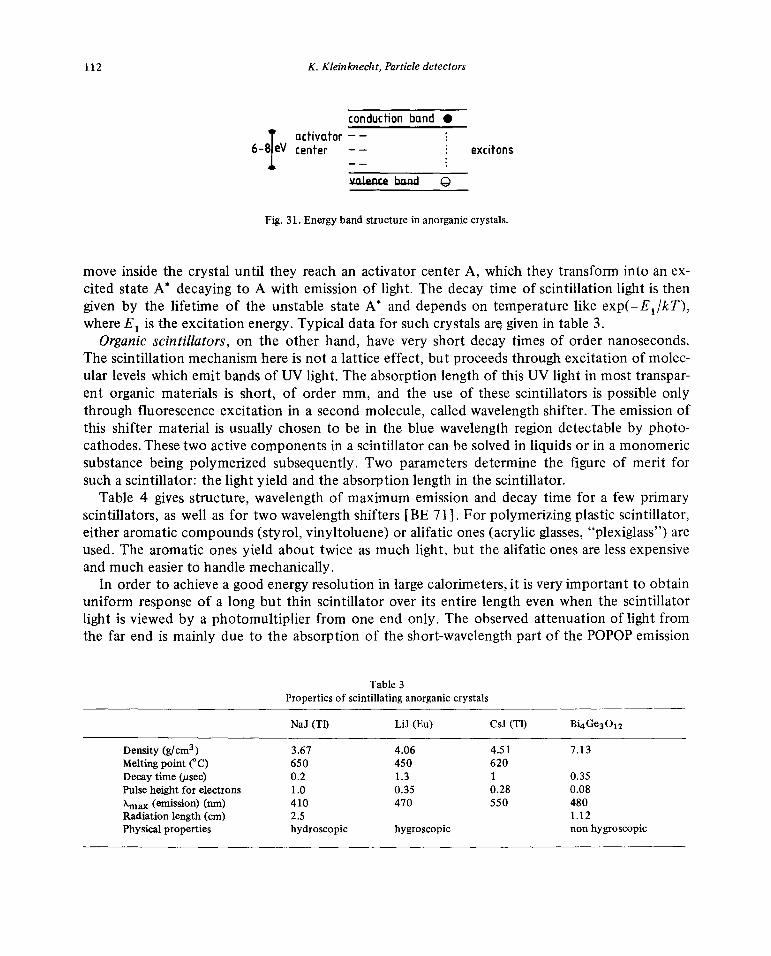
112 K. Kleinknecht,Particledetectors
conduction band •~ activator — —
6—8 eV center — — excitons
valence band 0
Fig. 31. Energy band structure in anorganic crystals.
move insidethe crystal until they reachan activatorcenterA, which theytransforminto an ex-cited stateA~decayingto A with emissionof light. The decaytime of scintillationlight is thengiven by the lifetime of the unstable stateA* anddependson temperaturelike exp(—E1/kT),whereE1 is the excitationenergy.Typical datafor suchcrystalsar~given in table3.
Organic scintillators, on the other hand, havevery short decay times of order nanoseconds.The scintillationmechanismhereis not a lattice effect, butproceedsthroughexcitationof molec-ular levelswhich emit bandsof UV light. The absorptionlengthof this UV light in mosttranspar-ent organic materialsis short, of order mm, and the use of these scintillatorsis possibleonlythrough fluorescenceexcitation in a secondmolecule,calledwavelengthshifter.The emissionofthis shifter materialis usually chosento be in the blue wavelengthregion detectableby photo-cathodes.Thesetwo activecomponentsin a scintillator can be solved inliquids or in amonomericsubstancebeing polymerized subsequently.Two parametersdetermine thefigure of merit forsuch ascintillator: the light yield andthe absorptionlength in the scintillator.
Table 4 gives structure,wavelengthof maximumemissionanddecaytime for a few primaryscintillators,as well as for two wavelengthshifters [BE 71]. Forpolymerizing plasticscintillator,eitheraromaticcompounds (styrol,vinyltoluene)or alifatic ones(acrylic glasses,“plexiglass”) areused.The aromaticones yield about twice as much light,but thealifatic ones arelessexpensiveandmuch easierto handle mechanically.
In order to achieve a goodenergyresolutionin largecalorimeters,it is veryimportantto obtainuniform responseof a long but thin scintillator over its entirelength evenwhen the scintillatorlight is viewedby aphotomultiplier from one endonly. The observedattenuationof light fromthe far end is mainly due to the absorptionof theshort-wavelengthpart of the POPOPemission
Table3Propertiesof scintillatinganorganiccrystals
NaJ (Tl) LU (Eu) CsJ (Tl) BL~Ge3012
Density(g/cm3) 3.67 4.06 4.51 7.13
Meltingpoint (°C) 650 450 620Decaytime (jJsec) 0.2 1.3 1 0.35Pulse height for electrons 1.0 0.35. 0.28 0.08Xmax (emission)(nm) 410 470 550 480Radiation length (cm) 2.5 1.12Physical properties hydroscopic hygroscopic nonhygroscopic

K. Kleinknecht,Particledetectors 113
Table 4Organic scintifiatorsand wavelength shifters
Primary Structure Xmax Decay Yield/scintillator emis. time yield
(nm) (ns) (NaJ)
Naphthalene 348 96 0.12
Anthracene ~JJJ 440 30 0.5
p-Terphenyl ~ 440 5 0.25
PBD ~ 360 1.2
Wavelengthshifter
420 1.6
bis-MSB ~CHcH~cHcH~ 420 1.2
spectrum,as shown [KL 81b] in fig. 32. In order to obtain a moreuniform responseit is there-fore possibleto filter out theshortwavelengthpart.Theeffect of a filter at 430nm can be seenin fig. 32: the light yield at the endof the scintillator nearto thephotomultiplieris diminisheddrastically,while the onefrom the far endis influenced muchless.
Still, by usingthe filter, light is lost, andit is interestingthereforeto searchfor an acrylic scm-tillator with long attenuationlength andhigherlight yield thancommerciallyavailable.Onenewmixture found [KL 81b] recentlycontains3% naphthalene,1% PBD and0.01% bis-MSB. The at-tenuationcurves for a scintillator of this material with size 1800 X 150 X 5 mm3 areshowninfig. 33. The attenuationlengthwith blackend andfilter is A = 210cm, and the light yield at 160cm from the photomultiplierside is 20% higher thanthe one for the commercialmixture plexi-glas 1921 (1% naphthalene,1% PBD, 0.01% POPOP).This newscintillator is usedthereforefor anew neutrinocalorimeterof the CDHS collaboration(fig. 77).
Importantdevelopmentsof low costscintillatorshavebeen doneat Saclay [BO811 for experi-mentsat the proton—antiproton colliderat CERN. Two newgroupsof scintillatormaterialhavebeendeveloped:i) the KSTI line based onpolystyrenematerial which can beextrudedbetweentwo polishedrolls; it has80—100%of the light output ofthe PVT-scintillatorNE1 10, an attenua-tion length of 80 cm for sheetsof 3 mm X 200mm cross-sectionanda decaytime of 3 ns,how-evercareful handlingis requiredas for other aromaticscintillators; ii) the Altustipe seriesbasedon polymethylmetacrylate(PMMA) with similar propertiesas Plexipop,i.e. 20—50%of the lightoutput ofNEllO, andattenuationlengthsof 1.0—1.5m.

114 K. Kleinknecht, Particledetectors
6 ~hOUtfd~AR : : I bis -MSB I
400 460 480 520 [nm] .~ •A AA
430mm wave Length £ 2 . . • •
6without filter FAR “ U •
170cm from light guide 2 U • -
400 440 480 520 [n~) 0 40 80 L 120 160 cm430nm wave Length
Fig. 33. Attenuation curvesin a scintifiatorof dimensionsFig. 32. Wavelengthspectrumoflight producedat nearend 1800 X 150 X 5 mm
3 without filter, reflecting end (fulior far end of scintillator (type plexiglas 1922, 180 cm long) dots), black end (open circles);with yellow filter, reflectingwith andwithout yellowfilter at 430 nm [KL 81b]. end (triangles), black end (squares), [KL81b].
3.3. Light collection
The traditionalway of collectinglight from ascintillator is the adiabaticlight guide. The(blue)scintillation light travels down the scintillator plate by multiple internal reflection. The usuallyrectangularradiatingsurfacewith cross-sectionF is imagedonto the photocathodesurfacef bymeansof bent transparentplastic rodsor strips such that the radiusof curvatureof the rods islargecomparedto their thickness.In this way it can beavoidedthat light hits an internalsurfaceunder an anglelargerthanthe oneof total reflection. The amountof light reachingthe photo-cathodeis lessthanf/F dueto Liouville’s theorem.
The time resolutionof direct-coupledscintillationcounterscomes fromtwo sources:the transittime jitter of the photomultiplier and the time differencebetweendifferent light pathsin thescintillator andlight guide. The lattercontributiondepends mainlyon the scintillatordimensionsanddominatesfor large(�2m) counters,as shownby the data in fig. 34. For largecountersys-tems,a resolution belowa~ 200pshasnot beenachieved.

K. Kleinknecht, Particle detectors 115
(1 0 LONGSCINTILLATORS
0200 0 •RISETIME-’300p
. ~ -~ ~ “
100 L SMALL• o J SCINTILLATORS
-I~1’T7~~~CULATEDRESOLUTIONRISETIME
100—400psDECAYTIME 1500ps
0 500 1000
PM Transit time spread (psI
Fig. 34. Comparison of r.m.s. time resolutionsof scintillation counters vs. the r.m.s. transit time spreadin thephotomultipliersused.Small scintillators with dimensionsbelow 1 cm arecomparedto long scintillators (length —2 m, thickness2—5 cm,width20—40cm),[CA81b].
An alternativemethod,dueoriginally to Garwin [GA 60, SH 51], hasbeenrevivedrecentlyforapplicationsin large-scalecalorimetry[BA 78, SE79]. The principle is shownin fig. 35: bluelightfrom the wavelengthshifter (e.g. POPOP)leavesthe scintillator andenters,throughan air gap, asecond shifterbar.This rod is madeof acrylic materialdopedwith a molecule(BBQ, e.g.)absorb-ing the blue light andemittingisotropically green light(around 480 nm,seefig. 36). A part (10—1 5%) of the greenlight is catchedby the shifter barby internalreflectionandreachesthephoto-
PM — — — —~ green shifter bp~~jAir gap
emi~%:ed blue
7~~NIGj~J
Fig. 35. Principle of wavelengthshifterbar technique.

116 K. Kleinknecht, Particle detectors
I I
—. — BBQ Emission
10 - ...-. .—~. — — — Absorption\ —PBD Emission
I \POPOP Emission
200 300 400 500 600 700
X (nm)
Fig. 36. Absorption and emission spectraof BBQ.
multipliers looking at the endof the bar. Themain problemsin developingthis techniquewere i)to find the appropriate shiftingmaterialmatchedto the POPOPemissionspectrumandthe photo-cathodespectralsensitivity; ii) to find a way of optimizing the self-absorptionin the green bar.
Theseproblemswere solved [BA781 by takinga 90 mg/Q concentrationof BBQ in plexiglas218. The productnow is commerciallyavailableandhasfound wide applicationin largeexperi-ments.
The thicknessof thegreenshifter barneededfor absorptionof thePOPOPlight can beobtainedfrom fig. 37, wherethe intensityof BBQ emission hasbeenmeasured[KL 8lal as a functionofthicknessof the greenbar. An absorptionlength of A = (5.2±0.2) mm is obtainedfor the BBQconcentrationmentioned.
The shifter bartechniquecan be usedto collectthe light from very largescintillatorswith a fewphotomultipliers.Oneexampleis the CFRneutrinocalorimeter[BA 78] with countersof 3 X 3 m
~1~2b364~ ID/mm
Fig. 37. Measurementof absorptionlengthof POPOPlight in BBQ [KL 81a].

K. Kleinkncc/it,Particledetectors 117
500 ~ 500
400 - 400
300 - - 300 -‘I,
C
>
200 - 200
100• 100-
111111 huh 111111 111111
-24 -12 0 12 24 24 12 0 12 24t~X(crn) AY(cm)
Fig. 38. Deviation of reconstructedposition of a showerof 100 equiv.particlesfrom real position;r.m.s.deviationo~ (7.3±0.1)cm, o, = (7.6±0.1) cm [KL 81a].
viewed by 4phototubesat thecorners.These 4pulseheightscanbe usedto calculatethecenterofgravity of a showerof particles.Fig. 38 showsresultsof ameasurementdone witha 150X 300X 1.5cm3 acrylic scintillatorviewed inthis way. The positionof a showerwith 100 equivalentparticlescan bereconstructedwith an accuracyof a ‘— 8 cm [KL 81a]. Thismethod,therefore,hasthead-vantageof allowing to savephotomultipliers,savemechanicalwork for light guidesandpermittinga measurementof thepositionof a showerof particles.It doesnot,however,permitto disentangleseveralshowers.
One disadvantageof the wavelengthshifterBBQ is its two-componentdecaytime with lifetimes[KL 81 a] of 18 ns and 620 ns, which causestiming difficulties when measuringpulseheights.
3.4. Planarsparkcounters
Thesecountersconsist of two planarelectrodesgeneratingan electric field abovethe staticbreakdown,i.e. at a ratio of field strengthE to gaspressurep of E/p —‘ 30—60 V/(cm Torr). Theprimaryionization of a passingchargedparticledevelopsinto a spark,and the largecurrentdrawnby this sparkcan berecordedas a fastrising pulse.In counters withmetallic electrodes[KE 48]the sparkdischargesthe total capacityof the plates, leadingto hightemperaturesandburningofthe electrodes.The damagedsurfacegives spontaneousbreakdownsat lower fields. A possibilityof avoidingthis deficiencyconsistsin usingmaterialwith high resistivity(a = 10~—10’°~2cm)forone of the electrodes[BA 56] The spark then only dischargesa small areaof the condensoraround the primary ionization,leadingto a lower energydensityin the spark.Fig. 39 shows aschematicof such acounterwith copperstrip readouton thesemiconductinganode.The imped-anceof this strip line can be matchedto the readoutcable.Countersareoperatedwith argonat

118 K. Kleinkncc/it, Particledetectors
COPPER STRIPS .::..:::::u:::::::::::,::::::::::::,::::~~:::::::::: SPACER
- - GLASS
-HIGH VOLTAGE,/~~ ‘T.
CATHODE Cr.Cu COATED GLASS
Fig. 39. Schematic viewof a typicalplanarsparkcounter [BR 81].
5—10 atmospheres,addinghydrocarbons (isobutane, ethane,1 .3-butadien)in order to absorb UVphotonsfrom the sparkthusavoidingsecondarysparking[BR 811.
The time jitter of the signal, 6, dependson the electricfield E andthe numberof primaryionsN, like 6-~-l/(E~~/7~).Measuredvalues [BR 811 are 6 30—80 ps for countersof 10 X 10 cm2area havingdetectionefficienciesof > 95%. The distributionof thetime differencebetweentwoparallelsparkcountersis not quite gaussian, showingbroadtails (fig. 40).
Despitethe excellenttiming characteristicsof thesecounters,wide applicationis not yetfore-seeablebecauseof the extremedifficulties in manufacturing andmaintaining the high-qualitysurfaces.
300
EVENTS G = 62 ps 72 kV
200
:i .{~\ .
1000 1500 2000At(ps]
Fig. 40. Distribution of timedifferenceoftwo planarspark counters.A gaussianis fitted to the histogram in theregionwhere thecurveis drawnassolid line [BR 81].

K. Kleinkncc/it,Particledetectors 119
4. Identificationmethods
4.1. Time-of-flight
The identificationof charged particlesthroughtheir flight time betweentwo scintillationcoun-ters requires,for momentaabove I GeV/c, very goodtime resolutionandquite longflight path.The time differencebetweentwo particleswith massesm1 andm2 is for a flight pathL
= L/(131c) — L/(132c)= (L/c)(’Jl + m~c2/p2— \/l + m~c2/p2),
which for p2 ~ m2c2 becomesi~t~— (m~— m~)Lc/(2p2).Fig. 41 showsflight time differencesbetweenpairs of chargedparticles.Using conventionalscintillation counters(section 3.3)with atime resolutionat = 300 ps, 7r/K separationat the level of 4a~would requirea flight path of3mat I GeV/c and 12 m at 2 GeV/c. If parallelplatesparkcounterswould comeinto operation,therequiredflight pathwould be reducedto 0.5 mor 2 m, respectively.
For this methodof identification, therefore,at presenta very long flight path is needed.
4.2. Cherenkovcounters
Cherenkovradiation [CE 64] is electromagneticradiation emitted by charged particlesof ve-locity u traversingmatterwith refractiveindex n if v> c/n. The classicaltheoryof the effect attri-butes this radiation to the asymmetricpolarization of the medium in front of and behindthechargedparticle resulting in a net electric dipole momentvarying with time. The radiation isemitted at an angle0, wherecos0 = (ct/n)/(j3ct)= l/(13n). The thresholdfor Cherenkov-effect,~3> 1/n, correspondsto a thresholdin the ‘y factorof the particle,
y> l/sjl — I/n2
Typical refractiveindicesandthresholdvaluesaregiven in table5. Unfortunatelythereis a gap in
~ ~0~p (GeV/c)
Fig. 41. Differencesof time of flight t
1 — t2 of particle pairseli, irK and Kp for a flight path of 1 m.

120 K. Kleinknec/it,Particledetectors
Table 5Cherenkovradiators
Material n — 1 .y (threshold)
Glass 0.46—0.75 1.22—1.37Scintillator (toluene) 0.58 1.29Plexiglass (acrylic) 0.48 1.36Water 0.33 1.52Aerogel 0.025—0.075 4.5—2.7Pentane(STP) 1.7 X it1
3 17.2CO
2 (STP) 4.3 X 10~ 34.1He (STP) 3.3 X i0~ 123
the refractive indices betweenthe gaseswith highestindex (pentane)andpractical transparentliquids with lowest index. The developmentof silica—aerogel[CA 741 consistingof n(Si02) +
2n(H20) has closedthis gap andpermits avelocity measurementin the rangeof ‘y -~3—5, wherethe specificionization is nearlyconstant.
Large scaleproductionof silica—aerogelwith n = 1.03 andn = 1.05 in blocks of 18 X 18 X 3cm
3 is now possible [HE81]. The Cherenkovlight has been collectedby cylindrical mirrors[CA 81a] or byadiffusor box[AR 81] behindthe aerogelblock (fig. 42) andrecordedby photo-multipliers. 6—12 photoelectronshave been obtainedfrom a 15—18 cm long radiator of thismaterial(n = 1.03).
PM SIDE VIEW
— ~ _\_j
18 TOP VIEWXAxis
~L~J-~L-?~~14°2O
AEROGEL
(a) Distances in cm (b)
Fig. 42. Silica—aerogelcountersusedin EMC experiment.Particlesincidentfrom left onaerogel,diffusingbox coveredinternallywith mililpore filter [AR 81].
K. Kleinknec/it,Particledetectors 121
From the relation cos0 = l/(13n) follows that themaximumCherenkovanglebecomessmallerif n approachesunity. The energyradiatedperpathlengthin the radiatoris
dE 2irah 1’ / 1 \—,~--——~-- jU.) c ~n>l f3n
with a beingthe fine structure constant,a = 1/137.This leadsto the numberof photonsN emit-ted overa pathlengthL in the wavelengthinterval A1 to A2
X2
N = 2iraL f dA sin20/A2
XI
For a detectorsensitive inthe visible region A1 = 400 nm,A2 = 700 nm, thiscorrespondsto N/L
= 490 sin20 photons/cm.Evidently, the detectionof UV-light can increasethis yield by afactor
of 2—3.The length of Cherenkovthreshold detectorsneededfor separationof particlesof momentum
p increasesas p2: supposetwo particleswith massesm1 andm2> m1 haveto be distinguished.
Then the refractive index of the radiatorcan bechosensuch that theheavierparticlewith massm2 doesnot yet radiate,or is just below threshold,f3~ I/n
2, and n2 = ‘~/(‘y~— 1). Then theamountof Cherenkovlight from the particlewith massm
1 is proportionalto
sin2O = 1 — I/(j3~n2)
which for ~y~ I becomes
sin20~n~c2(m~—m~)/p2
In a radiator of lengthL, detectingphotonswith a quantumefficiency of 20%, thenumberofphotoelectronsis
P 100Lc2 (m~— m~)/(p2L0),
whereL0 = 1 cm. In order to obtainP = 10 photoelectrons,alength
L/L0 p2/((m~— m~)c2 10)
is required in the optimistic caseassumingthat a radiatorwith exactly the refractive index re-quired above can befound.
For practicalpurposes,oneusesa combinationof thresholdcounters withdifferent refractiveindices,as indicatedin table 6. By usingtwo ormoreof thesecounters,pions, kaonsand protonscan beidentified inthe momentumrangegiven in fig. 43.
Apart from this utilization of the Cherenkov threshold,the angleof Cherenkovemission canalso bemeasuredin order to identify particles.Theconicalemissionpatternaroundthe radiating

122 K. Kleinknec/it,Particledetectors
Table 6Possible choicesof Cherenkovthresholdcounters[LE 81c]
Counter Refractive Radiative Radiator Counter Lightindex medium length length yield
A 1.022 Aerogel 20 (cm) 50—100 (cm) 5—6 (e)B 1.006 ?(Aerogel) 50—100C 1.00177 Neopentane 30 50D 1.00049 (N
20—C02) orFr14 100 ~120 ~10E 1.000135 (Ar—Ne) orH2 185 ~200 5
0.66 2.34 4.5 8.5 15.8 30 57 (GeV/c)I.
I I ICOUNTERS IAB _________________ ________ ________ABC _______ _______ _______ IABCDOABDOACD I it
ABCDE F 4 1 H
AB F -jABC I IABCO IABCDE 4 4 KABD I IACD I- I
AB I IABC I 4ABCO I 4ABCDE 4 I pABD I I I I— IACD -j I 1
Tof,t/K
Tot K/p (————-4
lot It/p (-————-1
TOF dotted line indicate best performanceachievable with a classical system
I i i I ittil I situ I i i Ii ti~
0.2 0.5 1 2 5 10 20 50 100
Fig. 43.Domainofparticle identification for threshold Cherenkov counters as given intable 6 [LE 81c].
particlecan befocussedinto a ring-shapedimage.An adjustablediaphragmat the focustransmitsCherenkovlight emitted in a small angularrangeinto a phototube.Changingthe radiusof thediaphragm allows a scanthroughregionsof velocity. Differential gasCherenkovcounters[Li 73 1correctingfor chromaticdispersionin the radiator(DISC) have achievedvelocity resolutionsof‘~13/13~l0~.
Since the length of thesecountersis limited to a few meters,thereis a maximummomentumat which two kindsof particlescan beseparated(fig. 44). Separationof ir andK mesonsatseveral100GeV/c is possiblewith thesedevices.A velocity spectrumof chargedhyperonsin a short beamfrom an externalprotontargetis shownin fig. 45, demonstratingseparationof thesehyperonsat15 GeV/cmomentum.

K. Kleinknecht,Particledetectors 123
BEAM MOMENTUM FOR LIMITING irk SEPARATION (GeV/c)1 1) 100 1000 10000
I I T1ru I h rrr I I I TTTu I I rTr~
~ 10O~ —~k~—----- -~
-~ I~FFRE1 AL
1 RES D1D~’\ 2 ~N/A:0.4O
N \~1IHEP(1 }oDI~ ____
I 3~RNr~’PEDN)
4 CERN-IHEF ______
5 SPS- •~SC
BEAM MOMU~4TUMAT LIMITING RESOLUTION FOR THE SEF~IRATIONOFPAIRS OF PARTICLES (GeWc)
Fig.44. Highestbeammomentum for i/K separation vs. maximum Cherenkovanglefor threshold, differentialandDISC Cherenkovcounters [LI 73].
An alternative to changingthe radiusof the diaphragmconsistsin changingthe gas pressureandleavingthe opticalsystemin place.
While the DISC counterscan only be usedfor particles parallelto the optical axis of the de-tector,a velocity measurementfor divergingparticles fromaninteractionregionrequiresadiffer-ent approach.Seguinot andYpsilantis [SE 77] haveproposedthe ideaof a Cherenkovring imag-ing detector(fig. 46). A sphericalmirror of radiusRM centeredat the interactionpoint focussesthe Cherenkovcone producedin the radiatorbetweenthe sphereof radiusRD and the mirrorinto a ring-shapedimage onthedetectorsphereof radiusRD. UsuallyRD = RM /2.

124 K. Kleinknec/it,Particledetectors
I I I-
it-
-
1.000 0.998 0.996RELATIVE VELOCITY ~ (:v/c)
Fig. 45. Velocity distribution in a shorthyperon beamselecting15 GeV/cparticles[LI 73].
particleI
D
target 6D2
particle 2Cherenkovradialing medium
Defectorradius RD
Mirror radius
Fig. 46.Principle of ring imagingCherenkovcounter [SE 77].
K. Kleinknecht,Particledetectors 125
CaF2 Crystal
__________________________________ 5 mm thick
5k7 Stainless steel mesh~2 4~8 — — — — —— — 5OO~spacing
V3 ______‘~—‘ —— 81% transparency
V4 3.23.5 . ~
2O~~W wires‘~—‘ 2 mm spacing
V4 -—
_________________________ Armodur
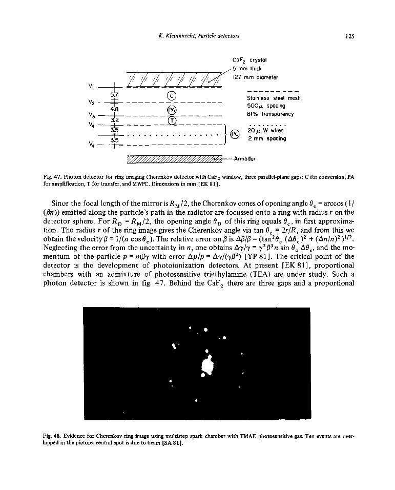
Fig.47. Photon detector for ring imagingChexenkovdetectorwith CaF2window, threeparallel-plane gaps: C for conversion,PAfor amplification, T for transfer, and MWPC. Dimensionsin mm [EK 81].
Sincethe focal lengthof themirroris RM /2, theCherenkovconesof openingangle°c= arccos(1/(/3n)) emittedalongthe particle’spathin the radiatorarefocussedontoa ringwith radiusr on thedetectorsphere.ForRD = RM/
2, the openingangle°D of this ring equalsOc, in first approxima-tion. The radiusr of the ring imagegivesthe Cherenkovangle viatan °c = 2r/R, andfrom this weobtainthevelocityj3= I/(n cosOc). Therelativeerror on 13 is ~f3/f3= (tan20~(~O~)2+ (~n/n)2)’/2.Neglectingtheerror from theuncertaintyin n, one obtains1~.y/’y= ‘y2f33n sin 0~~ andthemo-mentum of the particlep = mj3y with error i~p/p= ~y/(y132) [YP 811. The critical point of thedetector is the developmentof photoionization detectors.At present[EK 811, proportionalchamberswith an admixture of photosensitivetriethylamine (TEA) are under study. Such aphoton detectoris shown in fig. 47. Behind the CaF
2 thereare threegapsand a proportional
Fig. 48. Evidencefor Cherenkovring image usingmultistepspark chamber with TMAE photosensitivegas. Ten eventsareover-lapped in thepicture; centralspot is dueto beam [SA 81].

126 K. Kleinknec/it,Particledetectors
chamber(PC). In gap C photonsare convertedby TEA to photoelectrons,gapPA servesfor pre-amplification, gap T for transferand PC for avalanchemultiplication. Threephotoelectronsperincident 10 GeV/c pion traversing1 m of argonCherenkovradiatorat 1.2atm.pressurehavebeenobserved.Developmentof suchdetectorsis continuing.Amongstthe possibleimprovementsisthestudy of a new photosensitivegas [NA 72], Tetrakis-dimethylaminoethylene(TMAE), having aphoto-ionizationpotential of 5.4 eV, lower thanthe oneof TEA, 7.5 eV. Using thisvapour,evi-dencefor Cherenkovring imaging has beenobtainedas shownin fig. 48, whereten events havebeenoverlappedin the picture [SA 811.
4.3. Transition radiationdetectors
If a chargedparticletraverses amediumwith varyingdielectricconstante.g. a periodicseriesoffoils andair gaps,radiationis emittedfrom the interfaces betweenthe two materials.This “tran-sition radiation” (TR) was showntheoreticallyby GinzburgandFrank [GI 461 to dependon the~ factor of the moving particle, thuspermitting an identification of particlesin the very highenergyregion(y> 1000) whereothermethodsfail.
The intensity of this radiation is expectedtheoretically to have asharp forwardpeak at anangle0 ‘—j 1/y and to be proportionalto y. If a periodicsandwichof many foils is used,interfer-enceeffects [AR 75, FA 75] will producea thresholdeffect in y, such that thedetectorcan beusedfor discriminatingbetweenparticlesof differentmass.
600- .~ -
1.04cmXe~‘ ,rWITH Li 1.4GeV/c
f ~ eWITH DUMMY
~4OO~[ ~
o - ~ eWITH LiU-
oci I2 ‘1 -
200- -
~
C ,~-,—~—.
0 10 20 30 40 50 60 70 80 keV
PULSE HEIGHT
Fig. 49. Pulse height spectrumof transition radiation in Li foils detected by a xenonproportional chamber [FA 80].
K. Kleinknec/it,Particledetectors 127
Practicalapplicationshavefollowed the demonstrationby Garibian[GA 73] that TR isemittedalso in the X-ray region. Actual TR countersconsist of a radiatorfollowed by aproportionalchamberfor the detectionof the X-rays emitted forward. Since the absorptionof X-rays in theradiatormaterial behavesas Z3~5,the atomic numberof the foils hasto be as low as possible.Inthe pioneeringwork of Willis, Fabjan andco-workers[CO 77] thetechnologyof thin lithium (Z 3)foils has been mastered.As a countinggas for the X-ray detector, xenon(Z 54) hasbeenused.
The pulseheightspectrumin a xenon chamberbehind1000 Li foils of 51 ~zthicknessis shownin fig. 49 togetherwith a spectrum froma dummy radiatornot producingTR. The pulseheightfrom TR can beclearlyseparated fromthe onefrom ionization loss only.
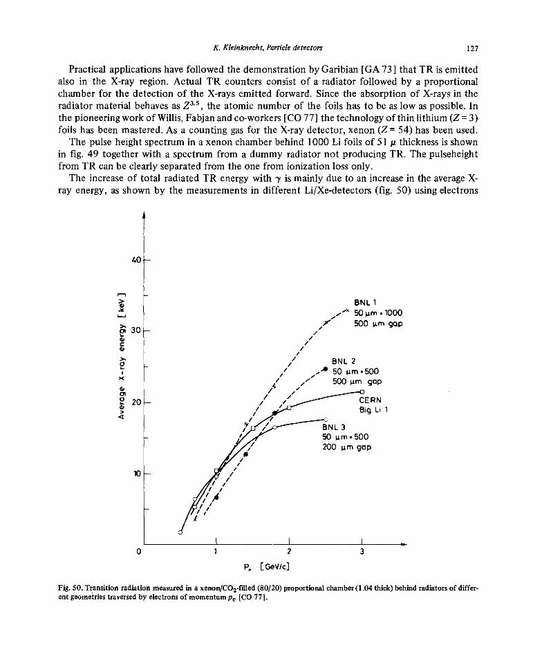
The increaseof total radiatedTR energywith y is mainly dueto an increase inthe averageX-ray energy,as shownby the measurementsin different Li/Xe-detectors(fig. 50) usingelectrons
40 —
BNL1~X 50 jim ‘.1000/ 50Oj~mgap
ai3O—
- BNL2.~‘ 50 jim-500
/ ,‘ 500jim gap,4 I.,
~ 20— ~1 ‘~ CERN/ BigLil
4 / /7 /‘ BNL3
- / 50 im’.SOO// 200 jim gap
a/
//10— /
///I,
//
I’
0 1 2 3
p~ [0ev/c]
Fig. 50.Transitionradiationmeasuredin axenon/C02-filled(80/20) proportional chamber(1.04 thick)behindradiators ofdiffer-
ent geometriestraversedby electronsof momentum Pe [CO77].
128 K. Kleinknecht,Particledetectors
with ~ —~2000—6000.From theseexperimentswe can concludethat i) TR detectorsat themo-ment can be usedfor y> 1000, i.e.for electronsabove 0.5GeV/c andpions above 140 GeV/c.ii) The extensionof this methodbelowy = 1000 requiresthe detectionof 1—5 keV X-rays.
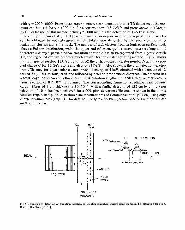
Recently,Ludlam et al. [LU 81] haveshownthat an improvementin the separationof particlescan beobtainedby not only measuringthe total energydepositedby TR quantabut countingionization clustersalong the track. The numberof suchclustersfrom an ionization particletrackobeysa Poissondistribution, while the upperendof an energyloss curve has a verylongtail. Ifthereforea chargedparticlebelow transition thresholdhasto be separated froma particlewithTR, the region of overlap becomesmuch smallerfor the clustercounting method.Fig. 51 showsthe principle of method [LU 81], andfig. 52 the distributionsin clusternumberN andin depos-ited chargeQ for 1 5 GeV pions andelectrons[FA 81]. Also shownis thepion rejectionvs. elec-tron efficiency for a particularcluster thresholdenergyof 4 keY, obtainedwith a detectorof 12setsof 35 ji lithium foils, eachonefollowed by axenon proportionalchamber.The detectorhasa total length of 66 cm anda thicknessof 0.04 radiationlengths.For a 90% electronefficiency,apion rejection of 8 X 1O~is obtained.The correspondingfigure for a radiatormadeof purecarbonfibres of 7 jim thicknessis 2 X iO~.With a similar detectorof 132 cm length, a kaonrejectionof 102 hasbeenachievedfor a 90% pion detectionefficiency,as shownin the pointslabelled Exp.A in fig. 53. Alsoshownaremeasurementsof Commichauet al. [CO 80] usingonlychargemeasurements(Exp.B). This detectornearlyreachestherejectionobtainedwith the clustermethodin Exp.A.
-DV, +H,V,
:F. TR s-ELECTRON
o THRESHOLD
BEAM 1~ ~m1~j~TIME
_____________ ...—~NODESRADIATOR : •
FIELD.- ~~wIRES
E~
LONG. DRIFTCHAMBER
Fig. 51. Principle of detection of transitionradiation by counting ionizationclustersalong the track. TR: transition radiation,D.V.: drift voltage [LU 81].

K. Kleinknecht,Particledetectors 129
N DISC
0
_ 1~ :: e ~40Oin ~ 600z
~0 200
0 _____________ _______________III 0 ______________0 5 10 5 20 2 6 10 4
N clusters Q, keV,/setI I I
•AUIOGeVO~0 15 GeVRADIATOR Li II
cm 12 sets
z0
10~z
z00
~ADC,THR’.4 key)z0 I0~-~
N(DISC,THR~4 key)
1.00 0.90 0.80 0.70
ELECTRON EFFICIENCY
Fig. 52. Upper part: distributionin cluster number N and in deposited chargeQ for pionsand electrons.Lower part: ir/e separa-tion by thresholdin Qor in N [FA 81].

130 K. Kleinknecht,Particledetectors
10~’
-
I I I
1.00 0.90 0.~0 070
EFFICIENCY FOR KAON
Fig. 53. ir/K separationfor a givenefficiency of K mesondetectionat 140 GeV/cbeammomentum. Exp.A [FA 81] has24 radia-torsof carbonfibres followedby Xe chambers, withtotal length132 cm, Exp.B [CO 80] has 20 setsof 5 ~tmmylar foil stacksand chambers, total length 147 cm.Q: charge discrimination, N: clustercounting.
4.4. Multiple ionization measurement
Betweenthe region(7> 1000),wheretransitionradiationcan beutilized, andthe mediumandlow energydomain,y < 100,whereCherenkovcountersandtime-of-flight measurementareprac-tical, thereis a regionof y between100 and 1000 whereneitherof thesemethodsis applicable.Here anew kind of detectoris provided by the exploitationof the relativistic riseof the ioniza-tion energyloss in this domain(seefig. 1). In gases,thisenergyloss risesby afactorof 1.5, andvery precisemeasurementis required.Becauseof the Landautail from knock-onelectrons,theaccuracy inthe determinationof the meanenergyloss (or alternativelythe most probableenergyloss) doesnot improve considerablyby increasingthe thicknessof the detector.However, theresolutionincreasesif the energyloss is measuredin many consecutivethin detectorsandif thelargepulse-heightsfrom knock-on electronsoccuringin someof the detectorsareremoved.Thisis done by taking the meanof the lowest 40—60% of ionization values. Thissamplingmethodwith truncationreducesfluctuationsin the meanandpermits a measurementof energylosspre-cise enoughin order to distinguishparticlesif their momentumis known. As can be seenfromfig. 54, theratio of most probableenergylossesof pions andkaonsat 100 GeY/c is 1.05, suchthat 7r/K separationat this energy requiresa r.m.s. resolutionof about2%. Such aresolutioncanbe achieved byusingseveralhundreddetectorswith a total thicknessof a few metersof gas.For128 chambers,by measuringthe averageof the 40% smallestpulse-heights,ar.m.s. resolutionofa 2.5% hasbeenobtainedfor 50 GeYpions and protons[LE 78a].

K. Kleinknecht,Particledetectors 131
e
1.6
1.4
K
LU~0
1.2
p
in. I
01 1.0 10.0p(GeV/c)
Fig. 54. Most probable energy loss inone cmof argon (80%)—methane(20%) mixture atSTP, for electrons,muons,ir and Kmesons and protons [MA 78].
36 , . . .....
20
10 - ‘>( ..,,>.:~><‘,,
9%
/ 11%
2 12’>~~..>~/,~/ ..‘
b 6’5’4 ‘~ “2
1 . .. ..I10 20 50 100 200 500 1000N
Fig. 55. Resolution expectedin energy loss measurementas a function of numberof samplingsN anddetectorlengthL(m). T=
L/N is the thicknessof one samplingdetector [AD 74].

132 K. Kleinknecht, Particle detectors
The dependenceof this resolutionon pressure,detectorlength and numberof samplings hasbeenstudied[AD 74]. The simpleststatisticalscalinglaw for the relativeerror on the energylossmeasurementfor 3 cm argon samplingis UE 5.6 (L p)’12 % with L beingthe detectorlei~gthinmetersandp the gas pressurein atmospheres.If oneincludesthe samplingthickness,a graphicalform of the relationis obtained(fig. 55). However,detailedmeasurementsshowthat theincreasein gaspressuredoesnot improve the resolutionas expected[LE 8la], (fig. 56). In addition, thedensityeffect for the ionization leadsto a considerablereductionof the relativistic rise (fig. 57).
14 • Ar 5%CH4
MF 64*4cm
71 PEAK
2 \
10- \~ -EPI\TEST\
EPIt8 ~ Pressure
~9..\Number~..~
6 ~—.. Expected(NTP)
Number of simultaneous particles4 $ 4 I I
I 2 3 4 5 6 7
NTP equivalent sample thickness
2~ :“ 62024 .~
Pressure ( atm ) —Fig. 56. dE/dx resolution obtained [LE Sla] by varying pressure (“Pressure”), by varying number of simultaneous particles(“Number”) comparedto expectationfrom EPI test [AD 74] at NTPwithout drift. Truncated mean of 64 samples 4 cm thick.

K. Kleinknecht,Particledetectors 133
I ARGON
1/10 —— 0.25 atm,
+ 5 / CH4 LE78o
5’./, CH4 /
1.8 4 20’/’. CH4 ~LE81Q /~/
4 20% CH4 FA79 /
* 00/, CH4 WA79
I/I 0.5
.6 1/ /‘“•‘• 2
•i ______—--f;07 ~t5
.4 ,ç,,~
,‘/I ~5
A~I./ _.—
,!P/7 ,It,,, ,~ ~
1.2
‘I/fl,,‘~,
,/4~Jj(
IC I I II 10 02 lO~ lO~
Fig.57. Relativisticriseof ionizationin argon—CH4mixtures.Numbersindicate pressurein atmospheres.
Thesetwo effects conspireto nearly deletethe advantagesof high pressure. In fig.58 the ratio ofdistanceD betweenthe truncatedmeanenergylossesof two particlesandthe resolutionCE forir/p ande/ir pairsis shownas a functionof pressure.Thereis only a marginal gain in going from1to 2 atmospheres.
This result is atvariancewith measurements donein aJADE typetestsetup[WA 82], where 1cm samplesof 4 atm Ar—CH4 givethe resolutionexpected fromfig. 55 for 4 cm samplesat 1 atm.
However, onthe basisof their results, Lehrauset al. [LE 81b] proposeas a ruleof thumbthatan experimentaldetectorwill have aresolution equalto theoneshownin fig. 55 but readingthegraphfor halfof the actualsamplingsize.

134 K. Kleinknecht, Particle detectors
A EPI‘~TEST
6__— 5cH
4
~ ~ S.7 SiC4 H~
°~~—a....~20CH4~ ~ ‘~Z~~’°~— 20 C2H6
5 ~ ~ 20 Co2
X H 0~’~..20C2H4e 2 6 7r/p
4~I 5 GeV/c ME 64x4cm
b4EPI
TEST
~~ 5 cH~
// 2OCO”~’~’—.. ~~~20C2H6~ I5~C~H1~ 2,0 20C2H4 20CH4
2 I 10C02.10C2H6
e/7r
0 2 4 6 8
Pressure (atm.) —
Fig. 58. ResolvingpowerD/a (seetext) for separationof lr/p or e/lr vs. gaspressurefor 15 GeV/cparticlesusingdE/dxmeasure-ment in 64 x 4 cm samples [LE 81a].
4.5. Comparisonof identificationmethods
The identificationmethodsdiscussed above are usable incertain momentumdomains:thetime-of-flight measurementat low momenta,then thresholdCherenkovcounters,DISC-Cherenkovs,multiple ionization measurement and,at ultrahigh momenta, transition radiation.The lengthre-quired for ir/K separationin thesedetectorsis shownin fig. 59. Using atypical detectorlengthofa fixed targetexperimentof 30 metersanda lengthof 3 metersfor storagering experiments,typ-ical momentumrangesfor inK separationare calculated,as shownin table7. It appearsthat themultiple ionization measurementis necessaryfor bridging the gapbetweenthresholdCherenkovandtransitionradiationcounters.

K. Kleinknecht,Particledetectors 135
15’ I I I
LENGTH FOR It /K SEPARATION
lm) IT.O.F. /THRESHOLD /DISC
10 - ) CERENKOV
I R~LATIVISTIC RISE
~S.
1 10 102 ~ 1O~
MOMENTUM (0eV/c)
Fig. 59. Length of detectorsneeded for inK separation by different identification methodsvs. momentum.
Table 7Identification methods
Method Domain for in/K separation Requirements
Fixed target Storage ring
geometry geometryL30m L3m
Time-of-flight p < 4 GeV/c p < 1 GeV/c = 300 psThreshold Cherenkov p < 80 GeV/c p < 25 GeV/c 10photoelectronsDISC-Cherenkov p < 2000GeV/c — achromatic gas counterRingimagingCherenkov p < 65 GeV/cMultiple ionization 1.2 <p < 100 GeV/c 1.5 <p < 45 GeV/c u~= 2.5%Transitionradiation 7> 1000 7> 1000 detectionof >10 keV
X-rays
5. Energymeasurement
5.1. Electron-photon showercounters
At energies well above1 MeY, the ionization loss of fast(~3 1) electronsis given by
— (4d~i) = 4inN0 ~ r~mc2 [ln(2mu2’y2/I) — 1]
ion

136 K. Kleinknecht,Particledetectors
withr~= (e2/mc2)2 (2.8 fm)2, while the competingloss by bremsstrahlungtakesthe form
fdE~ N0 22 183 E
—t—---- i 4a— Zr Eln— :—,\dx/ A e z113 X
0brem
wherethe “radiationlength”X0 is defined thisway, andm is the electronmass.While ionization dominatesatlow energies,bremsstrahlungtakesoverat high energies,andthe
ratio R of bremsstrahlungloss and ionization loss comesout to beR ZE/550,whereE is mea-suredin MeV. The energyat which this ratio becomesunity, the “critical energy”Ec thereforehasthe approximatevalueE~ 550/ZMeV which for lead is E~= 6.7 MeY.
The interactionof photonsat high energyis also governedby the radiationlength: the cross-sectionfor pair creation
Upair 4aZ2r~[~ ln(183/Z1/3)—
gives a probabilityP for pair creationin one radiationlength
,Np~Xo_7
Cpair A —;;- ~
Table 8 givesradiationlength andcritical energyfor somematerials[PA 78].The interaction of a high-energyphotonor electron thereforeleads to a cascadeof electrons
andphotons;startingwith aphotonof energyE0,after 1X0 we have 2particlesof averageenergy
E0 /2, after nX0 thereare2~iparticleswith meanenergyE0 /T~.The cascadestopsapproximatelywhentheparticlesapproachthecritical energy,i.e. if E0/2’s = E~.
The numberof generationsup to the maximum thereforeis n = ln(E0/Ec)/ln 2, andthenum-ber of particlesat the maximumN~ 2~ E0 /E~.The total integralpathlengthS of all electrons
Table8Radiationlengthand criticalenergy
Material X0 [g/cm2I E~[MeV]
H2 63 340
Al 24 47Ar 20 35Fe 13.8 24Pb 6.3 6.9LeadglassSF5 9.6 —11.8Plexiglass 40.5 80H20 36 93NaJ(Tl) 9.5 12.5BI4Ge3O12 8.0 7

K. Kleinknecht,Particle detectors 137
or positronsin the showeris approximately
n
e—2 V IV.i a?tT —,-~v ~2 \L’ IL’
Li — ~“o ~‘ 5o3~p — ~3”~o 55O’~’~’o1~c~v1
wheres0 is thepathlengthof electronsbelowthe critical energy.
The pathlengthS is proportionalto the total energyE0 if electronsandpositronscan bede-tecteduntil they cometo rest. In practical detectorsthereis aminimumkinetic energyrequiredfor detection(cut-off energyEk). This effect hasthe consequence[RO 52] that thevisible pathlength becomes[AM 81]
S=F(z)X0E0/E~
with F(z) ez (1 + z ln(z/1.526))andz = 4.58ZEk/(AEc).Including the effect of the cut-off energyinto Monte Carlo [CR62, NA 65, LO 75] calcula-
tions gives the followingpropertiesof electron—photonshowers:i) thenumberof particlesat maximumN~is proportionalto theprimaryenergyE0,ii) the total tracklengthof electronsandpositronsS is proportionalto E0,iii) thedepthatwhich themaximumoccursXmax increaseslogarithmically:Xmax/X0 = ln(Eo/Ec)
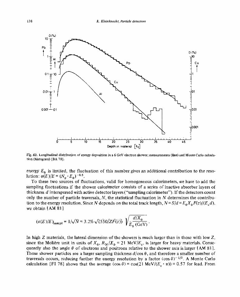
— t, wheret = 1.1 for electronsandt = 0.3 for photons.The longitudinal energydepositionin an electromagneticshowercan be seen in fig. 60as mea-
sured [BA 70] for 6 GeV electrons.A useful parametrisationfor this distribution is given by[LO 75]
(dE/dt)E0At° e_Pt
wheret~X/X0is the longitudinaldepthX in unitsof X0, andtheparameterst~ 0.5, t ~3tmax
andA =1/~(c~+ 1) vary logarithmically with energy.For proton energiesaroundI GeY, the
distributioncan beapproximatedby (dE/dt)= E0 0.06 t
2 e”2 for a leadconverter.The transversedimensionof a showeris determinedby the multiple scatteringof low energy
electrons.It turns out thatausefulunit for transverseshowerdistributionsis the Moliere unit RM= 21 MeV X
0/E~.As shownby the measurements[BA 70] in fig. 61, the distributionof showerenergyin transverse(radial)bins scaled inRM is independentof the materialused,and99% of theenergyare insidethe radiusof 3 RM.
The energyresolutionof an idealizedhomogeneousdetector ofinfinite dimensionsis limitedonly by statistical fluctuations.Fora cut-off energyof 0.5MeV anda critical_energyof 11.8 MeVa total track length of 176 cm/GeV anda resolutioncr(E)/E = 0.7%/v’E(G~V)have beencom-puted[LO 75].
If the showeris not containedin the detector, thefluctuationof the energyleakingout gives acontributionto the resolution.As shownin [DI 80], longitudinal lossesinducealargerdegrada-tion of the resolution than lateralones.An estimatefor thisfluctuationdueto longitudinal leak-ageis a(E) = (dE/dt)tr O(tmax), wheretr is the length of the detectorand cJ(tmax) the fluctua-tion of the position of the showermaximum. For photonsof I GeY energy,O(tmax)— I and(C(E)IE)Ieak= 0.06 t~exp(—tr/2). If the numberof photoelectronsN~detectedper incident
138 K. Kleinknecht,Particledetectors
D(’I.)
t 0(1.)11O~u
0001 01 001
- 0.001
I~i t~I !IIlI1I11l11 III!
0 5 10 15 20 25 30 35 40 45Depth in material [xo]
Fig. 60. Longitudinal distribution of energydepositionin a 6GeVelectronshower;measurements(line) andMonteCarlo calcula-tion (histogram)[BA 70].
energyE0 is limited, the fluctuation of this numbergives an additionalcontributionto the reso-lution: a(E)/E—(N~E0Y°~
5.To thesetwo sourcesof fluctuations,valid for homogeneouscalorimeters,we haveto addthe
samplingfluctuationsif the showercalorimeterconsistsof a seriesof inactiveabsorberlayersofthicknessd interspersedwith activedetectorlayers (“samplingcalorimeter”).If the detectorscountonly thenumberof particletraversals,N, the statisticalfluctuationin N determinesthecontribu-tion to theenergyresolution.SinceN dependson thetotaltracklength,N=S/d=E
0X0F(z)/(E~d),we obtain [AM 81]
(G(E)/E)sampi = Ik/~= 3.2%~(550/ZF(z))VEO(GeV)~
In high Z materials,the lateral dimensionof the showersis muchlargerthanin thosewith low Z,sincethe Moliere unit in units of X0, RM/X0 = 21 MeY/E~,is larger for heavymaterials.Conse-quently also the angleU of electronsandpositronsrelativeto the showeraxis is larger[AM 81].Thoseshowerparticlessee a largersamplingthicknessd/cos0, andthereforeasmallernumberoftraversals occurs,reducingfurther the energyresolutionby a factor (cos~> 1f2~ A Monte Carlocalculation [Fl 781 showsthat the average(cos0) = cos(21MeV/(E~ in)) 0.57 for lead. From

K. Kleinknecht,Particledetectors 139
I I I I I10O~i
— Monte Carlo (Cu)•CuOPbA Al
10
D1.
0.1- 00000
0
.I I I I I I
0 2 4 6 8 10 12
Fig. 61. Transversedistribution of energydepositionin a 6 GeV electronshower; data: points; Monte Carlo: histrogram;RM = 21MeV Xo/E~is the Moliere unit [BA 701.
this calculation,the samplingfluctuation gives a(E)/E = 4.6%/~/E( V) for 1 mm lead samplingthicknessandEk= 0.
Another largesourceof fluctuationsentersif the sensitive layersof the calorimeterconsistofa gas or a verythin layerof liquid argon(~2 mm), usedas proportionalcounters.Thenlow ener-gy electronsmovingat large anglesrelative to the showeraxis induce largepulseheightfluctua-tions (“path length fluctuations”), and the Landautail of the energyloss distributionalso leadsto a reductionof resolution.Thecomputedeffect of thesetwo contributionson the energyreso-lution of alead—argoncalorimetercan be seen in fig.62. The overall resolutionis 1 8%/\/E(GeV),morethantwice the samplingfluctuationof 7%/~E(GeV).
Homogeneous showercountersThe bestresolutionsare obtainedwith anorganicscintillating crystals. NaJ(Tl)detectorswith
a diameterof 3RM = 13 cm and l5X0 = 40 cm length have yielded [PA 80] a resolution of
a(E)/E = 2.8%(E(GeV))°~25in a large scaleapplication. For one24X
0 long countera(E)/E= 0.9%(E(GeV))°~
25has been achieved [HU721. The new type of crystal,_BGO(B4Ge3O12)
gives 8% of the light output of NaJ, and a resolution of cr(E)/E = 2.5%/v’E(GeV) [KO 81].

140 K. Kleinknecht,Particledetectors
I I I I I I
+
10 -‘S
\\ •-~....~~LANDAU
PATHLENGTH
5-
SAMPLI’JG FLuCTuATIONSI I I I I
0 2 4 6 8E (GeV)
Fig. 62. Contributions of sampling, path length and Landau fluctuations to the energy resolution of a lead—gasquantameter[Fi 78].
Leadglass countersdetect theCherenkovlight of showerelectrons,the resolutionis limited byphotoelectronstatistics.A computation[PR 80], basedon 1000 photoelectrons perGeY, givesa(E)/E = 0.006+ 0.03(~E)°~5,~ being the ratio of photocathodeareaandcounterexit area.Ac-tual measurements[BI 81] with 208blocks of 36 X 36 X 420mm3 give a resolution of a(E)/E= 0.012 + 0.053/\/E(GeV)for ~ = 0.35, in agreementwith the calculation.
SamplingshowerdetectorsThe resolutionof alead-scintillatorsandwichwith 1 mm leadand5 mm scintillator thickness
for a total lengthof 12.5 radiationlengthis shownin fig. 63 versusincidentenergy[HO 791. Thevaluesfor A = a(E)/-~J~vary from 7% GeY”2 at 100MeY to 9%GeV’12 at 5 GeY, in agreementwith a calculated5% GeY”2 from samplingfluctuations,3—4% GeV”2 from photoelectronstatistics,and2—5% GeV”2 from leakage.
In lead—liquid argon calorimeters, the ionization is sampledin a proportionalmodeby theargon chambersdefined by two lead platesas electrodes.Resolutionsfor 2 mm Pbplatesand3 mm liquid argon area(E)/E = 1 2%/..JE(GeV) [KA811..
A summaryon the energyresolution obtainedwith electron—photonshowercountersis givenin table9.
PositionresolutionThe impactpoint of an electronor photonon anarrayof showercounterscan beobtainedby
measuringthe lateral distribution of energyin the shower. Theprecisionof the positioninforma-tion increaseswith the numberof cells hit by showerparticles,anddecreaseswith the cell size.

K. Kleinknecht,Particledetectors 141
12
10
6-
0 I 1111.11 I 1111111 I I lilt
0.03 0.1 0.3 1.0 3.0 10.0E (6eV)
Fig. 63. The quantity u/.~JE(GeV)vs. E for a lead scintillator sandwich with 1 mm lead plates.Full line is contributionof leakage[HO79].
In particular, the accuracyis bestif the showerenergyis shared equallybetweentwo adjacentcells. Binon et al. [BI 81] usingcells of 36 X 36 X 420mm3,haveobtainedapositionresolutionof a~= 1.3 mm for 25 GeV electrons.Foralateralcell sized> 30 mm,an experimentalincreaseof ax is calculated(fig. 64) by theseauthors.On the otherhand, a variation of a, ~ IWEhasbeenfound [AK 77], confirming the assumptionthat the spatialresolution depends mainlyonthenumberof showerparticles.
With lead-scintillator sandwichesof 10 X 10 cm2 lateral dimensions[HO 79], the measuredspatialresolutionwas a, = 11 mm/’,/E(GeV).
Table9Electromagneticshower counters
Type Sampling Total a(E)/~J~ Spatial Angul Lateral Group Ref.thickness thickness %(GeV’12) resol.~.x resol. cell size(Xe) (Xo) (mm) (mm)
Na J — 24 0.9 E114 [HU72]Na J — 16 2.8 E”4 Crystal [PA 80, K! 79]
ball [CH 78b]Pb glassF8 — 17 5.3+ 1.2~/Zr 1.3 36 X 36 IHEP [B181]Pb glassSF5 — 12.5 s162+ 2.52E 6 10mrad 80 X 104 JADE [DR 80, BA 79]
Pb glassSF5 — 20 ~J62+ 0.52E 2 NA 1 [NA 1]Pb/scint 0.18 12.5 7—9 11WE(GeV) 100 X 100 ARGUS [HO79]Pb/scint. 0.21 13 9 25/,JE(GeV) 200 X 250 LAPP—LAL [SC81]
70 X 70Pb/LAR 0.36 13.5 10—12 5 5 mrad + strips TASSO [KA81]
20 mm
Pb/LAR 0.26 21 10 4 4mrad 23X23 CELLO [BE 81]Pb/LAR 14 11.5 Mark!! [DA79]Pb/PWC 0.5 12 16 Mark III [H!811Pb/prop.tube 1 28 13—18 pitch7.7 NA 24 [BA81]

142 K. Kleinknecht,Particledetectors
I I I I
o~(y) - -
(mm) 8 E~25GeV ,‘
0 50 100d~ CELL SIZE (mm)
Fig. 64. Positionx.m.s. resolutionas afunction of transverseblock size d for anarray of leadglassblocks.Full line: averageoverphotonimpact points acrosstheblock; dottedline: photonimpinging on centreof block. Point: measuredresolutionford 36mm [B!81].
5.2. Hadron calorimeters
The scalefor the spatialdevelopmentof ahadronicshower,the inelasticproductionof second-ary hadrons,which againinteractinelastically producingtertiary hadrons,andsoon, is given bythe nuclear absorptionlengthX. Fromthe inelasticcross-sectiona,A = A/(aN0p)can beobtained.The experimentalvaluesof A for materialsusablefor calorimetryare77 g/cm
2(C),135 g/cm2(Fe),210g/cm2(Pb)and 227g/cm2(U).Comparedto the small valuesfor the radiationlength of high Zmaterialsenablingthe constructionof correspondinglysmallshowercounters,the sizeof hadronicshowersis large; typical valuesfor Fe calorimetersare 2 metersdepthand0.5 m transversesize.The needfor suchsizesis demonstratedby the measurements[HO 78b] on thelongitudinalshowerdevelopmentshownin fig. 65,wherethe centerof gravity,the lengthfor 95% energycontainmentandthe length,wherethe averageparticlenumbergoesbelowone(“shower length”)aredisplayedas a function of incident pionenergyfor a 5 cm Fesamplingcalorimeter.A parametrizationof L(95%) can begiven: L(95%) = [9.4 lnE(GeV)+ 39] cm Fe. In a similar way, fig.66 giveslateralshowersizesfor 95% energycontainment;
Apart from the hadron showerparticles leakingout longitudinallyor laterally, the energyseenin asamplingcalorimeterfor hadronsis incompletefor severalreasons: -
i) thereare particlesescapingthe calorimetercarryingawayenergy,like muonsandneutrinosfrom pion decay(1% at 40 GeY),
ii) thereis nuclearexcitationandbreakupresultingin low energy‘y rays or heavyfragments,which do not reachthe sensitivepart of the sandwich(20—30% of total energyat 10 GeV).
This loss of visible energy,typically 30%, can be seen bycomparingthe light collected fromelectron-andhadron-inducedshowers iniron (fig. 67). Since in ahadronicshowertheelectromag-netic componentcanoccasionallybe dominantthroughenergeticin0 production,this loss inducesa fluctuationin responsewhich contributessignificantly to the resolution.

K. Kleinknecht, Particle detectors 143
25-
20-
15-
£ Shower length ..~ • + 140 GV
• 95/. contairwnent 10 -
150 - o Centre of gravity
I I~ ~I + I
50 GeV
010 ~ 2~ I I I I
E(GV) 0 20 40 60 80 100Showerdepth (cm)
Fig. 65. Showercenterof gravity in iron, length for 95% en-ergy containment andlengthwhereaverageparticle number Fig. 66. Lateraldimensionfor 95% energy containment asagoesbelow one asfunctionof pion energy[HO78b]. functionof depthin iron [HO78b].
On top of this fluctuation thereis the samplingfluctuationwhich alonegives riseto a resolu-tion abouttwice as largeas in electromagneticshowers (see 4.1). However, the effectsof the fluc-tuation in energyleakageandin the electromagneticcomponentof the hadronicshoweraremuchlargerhereandleadto energyresolutionsof about
o(E)/E ‘~‘ (0.9 — 0.5)WE(GeY),
if the thicknessof material betweenthe samplingdevices(“sampling thickness”)is below5 cm ofiron.
Two waysof improving thisresolutionhavebeen inventedandtried out successfully:i) The loss of visible energy through the nuclearexcitationandbreakupmechanismcan be
nearly completelycompensatedby the energyrelease innuclearfission of 238U. Energeticphotonsfrom the fission contributeto the observedsignal such that the pulseheightfor hadronshowersbecomesnearly equalto the one for electromagneticshowers,as shown [FA 77] in fig. 67. Thecorrespondingfluctuationsdisappear,and the energyresolutiondecreases byabouta factorof

144 K. Kleinknecht,Particledetectors
3 - : : .“ U238Fe! LAp
. ~tU 238/LA V
‘p ‘-9 —
~ 2-
7/ 7V ‘—
0~1-
—70-~
I I I I I I5 10
Available Energy [0eV]
Fig.67. Detectedenergy deposition in sampling calorimetersof Fe andU for electrons, pions and protons vs. particleenergy[FA77].
two. Experimental resultsfor U calorimetersareshownin fig. 68, theycorrespondto
u(E)/E = 0.3/~JE(GeV),
which is only 50% higherthanthe lower limit given by samplingfluctuations.
30 x Fe 11.5mm)
U (1.7mm)
50 E— 100 150GeV
Fig. 68. r.m.s. energy resolutions obtained with hadronic sampling calorimeters; Fe (1.5 mm) and U (1.7 mm): [FA 77]; Fe(25 mm): [HO78b] and [AB81].
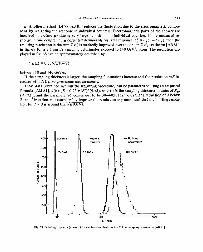
K. Kleinknecht,Particledetectors 145
ii) Another method[DI 79, AB 81] reducesthe fluctuationdueto the electromagneticcompo-nent by weighting the responsein individual counters.Electromagneticparts of the showerarelocalized, thereforeproducingvery largedepositionsin individual counters.If the measuredre-sponsein onecounterEk is correcteddownwardsfor largeresponse,E~= Ek(1 — CEk), thentheresultingresolutionin the sum ~E~is markedlyimprovedoverthe onein ~ Ek,asshown[AB 811in fig. 69 for a 2.5 cm Fesamplingcalorimeterexposedto 140 GeV/cpions.The resolutiondis-playedin fig. 68 can beapproximatelydescribedby
a(E)/E= 0.58/sJE(GeV)
between10 and140 GeV/c.If the samplingthicknessis larger,the samplingfluctuationsincreaseandthe resolutionalE in-
creaseswith d; fig. 70 givessomemeasurements.Thesedata (obtainedwithout the weightingprocedure)can beparametrizedusingan empirical
formula [AM 81], a(E)2 /E 0.25+ (R’ )2 (4t/3), wheret is the samplingthicknessin unitsof X0,t = d/X~,and the parameterR’ comesout to be 30—40%.It appearsthatareductionof d below2 cm of iron doesnot considerably_improvethe resolutionanymore,andthat the limiting resolu-tion for d -+ 0 is around0.5/V’E(GeV).
1600 - Electrons — Hadrons Hadronscorrected uncorrected
1400 -
15 0eV/c 75 0eV/c 140 0eV/c
1200-
r’~~1000-5’ I
L~800- ~ L.0E
I IZ I
600- I,
400 -
200-
L
—— . -~ , ~ . I
ido 500 lOOC)
E (nep)
Fig. 69. Pulseheightspectra(in n.e.p.) forelectronsandhadronsin a2.5 cmsamplingcalorimeter[AB 81]

146 K. Kleinknecht,Particledetectors
I I
£
>~
I .• 0•
-.
• J.PDISHAW (4000eV)(thesis)
• W Kienzle (10GeV)-~ £ CDHS1
CDHS2
0 5 10 15
Thickness, cm of Iron
Fig. 70. r.m.s. hadronicenergyresolutionfor iron calorimeterswith different sampling thickness;J.P.Dishaw [DI 79]; CDHS 1[H078b];CDHS2 [AB81].
The samplingof ionization in hadroncalorimeterscan bedoneby scintillators liquidargonion-ization chambers,proportionalchambers,or flashtubes.The choicebetweenthesedetectorsde-pendson thedesiredresolution,granularityandcost.For moderate-sizedgeometries,liquid argonandscintillatorsare usedfor best resolution. Forvery large fine graincalorimeters(ye scattering,proton decay), the proportionaltubes or flash tubesgive granularities downto 5 mm X 5 mm ata pricewhich still allows the constructionof multi-hundredton calorimeters.
5.3. Monitoring ofcalorimeters
In a typical large-scalecalorimetertherewill be severalthousandchannelsof analogpulseheightinformation which is convertedto digits andregistered. Asevereproblem withsuch anumberofchannelsis their calibrationand monitoring.
The calibrationcan bedoneby usingsuitablehadronbeamsandcalibratingthe responseof thecalorimeter,where for eachsamplingdetectorthe pulseheightis measuredin termsof minimumionization depositedby highenergy muons.
If there arenot as manymuonsin eachsamplingdetectoras areneededfor day-to-daymonitor-ing, anothersourceof calibratedpulseheightsis needed. Forliquid argon calorimeters,such asourceis obtainedby depositinga known amountof chargeinto the ion chamber.The same canbe donefor proportionalchambers.

K. Kleinknecht,Particledetectors 147
For scintillation counters,a novelkind of monitoringsystemshasbeenconstructedrecently[GR 80, El 80]. Thelight sourcehereis apulsednitrogen laseremittingat 337nm. Therearedif-ferentschemesof distributing thelight ontoa few thousandcounters.
In oneof the systems[GR 80], built for the UA1 experiment,the laserlight is injectedinto arectangular boxcoveredinsidewith a highly reflectingmaterial(millipore). After many reflectionsinside the light is diffuse andleavesthe box throughquartzfibers of 200j.tm diameter.This fiberhasattenuationsof —400 db/km in the UY. Eachof the 8000 fibers isconnectedto a plexiglasprism gluedto the center ofthe scintillator. The UV light pulsethenproducesscintillationlightwhich reachesthephotomultiplierandproducesa digital pulseheight.
In anothersystem[El 80], designedfor the improved CDHS detector, thelaserbeampassesthrough a filter, is widenedup optically, and then illuminatesa scintillator piece gluedonto aplexiglas rod (fig. 71). The blue POPOPlight emitted isotropically from the scintillator travelsdown the rodby internalreflection andis partially acceptedby the 2304 fibers groupedinto 144bundles of 16, eachbundlein one connector.The homogeneityof illumination of the fibers iswithin 1%. A mechanicalmaskmoving across infront of the connectorspermits onegroup of192 fibers at a time to be illuminated. Thisis requiredby the numberOf ADC channelsavailable.The transmissionof the fibers of 200~tmdiameter(QSF200A) is 180 db/km for the bluescintil-lator light, such that over alength of 25 m the attenuationis a factor of 2.8. Each fiberis con-nectedto a light guidethrougha small (4 mmdia.) cylindrical rod. With this system,by exchang-ing filters of different densityon a “filter wheel”, the linearity of all tubescan bemeasuredin adynamicrange from 1 to 2000 timesminimum ionization. The absolutecalibration is donebycomparingoneof the fiber outputsto the standardlight from anasourceembeddedin a scintil-lator.
D)STRIBUTOR FILTERSYSTEM LASER
~~:;: II I
Connectors Scinti(Lotor Lenses Mirror +JoulemeterFibers Wheels
50cm
Fig. 71. Dortmundlasercalibrationsystem[El 801.

148 K. Kleinknecht,Particle detectors
6. Momentum measurement
6.1.Magnetshapesfor fixed target experiments
In a fixed target interaction,the reactionproductsareusually concentratedin a conearoundthe incident beam direction (z), becauseof their limited transversemomentaand the Lorentzboost forlongitudinalmomenta.If such aparticlewith momentum(Fr, P~~ traversesahomo-geneousmagneticfield (0,B~,0), it receivesa transversemomentumkick
1~P~= —e fB~dz,
which gives for a field integralof 10 kG Ifl atransversemomentumchangeof 0.3GeV/c.The cor-respondingdeflectionof the particle is inversely proportionalto its momentum,andameasure-mentof theprojectedanglesin the(x,z)planeyields, inthesimplestapproximation, themomentum
P = e fB~dz/(sinO~— sin 0out)~
If themagnetizedvolumeis evacuatedandthe multiple scatteringin the positiondetectorsis neg-
lected,theerrorin momentum,.SP,comesfrom measurementerror ~x in the chambersalonet5P/P— 2(P/~P~)(~x/L),
if the leverarm for the anglemeasurementbefore andafter the magnetis L. For a field integralof 50kGm, 6x = 0.3 mmandL = 3 m this gives ~P/P— 1.3%at 100 GeV/c.
£~AIR~I) _©Cd
Fig. 72. Magnetshapesfor fixed targetexperiments,(a) H-magnet,(b) C-magnet,(c) toroidal ironcore magnet,(d) H-typeironcoremagnet.

K. Kleinknecht,Particledetectors 149
These“air core” magnetscomein different forms (fig. 72): H-magnets havesymmetricalfluxreturn yokes, C-magnetsasymmetricalones(and a lessuniform field). The amountof iron in theflux return dependson the desiredfield strengthin the air gap.For a cubic magnetizedregion,the volumeof iron needed,VFe, relativeto the magnetizedair gap volumeVMag for different fieldstrengthB in the gap isshownin fig. 73. If B hasto reachthe saturationfield strengthB~,thenVFe/VMag ‘—‘ 3, which is very uneconomical.More usualmagnetshaveB/B5 ~ to ~-
If the particlesto be analyzedare high-energymuons,a more economicalform of magnetsare“iron core” magnets(1CM). Herethe field linesstay completelywithin iron, eitherin the form ofa toroid, wherethe field lines arecircular arounda centralhole for the coils, or inakind of H-magnet,wherethe centralregion is also filled with iron (fig. 72). Themomentumresolutionhereis limited by multiple scatteringof the muonsin iron and the measurement errorof the muontrack. Multiple scatteringresultsin a meantransversemomentumchangeof
~pMS 21 (MeV/c)~/Z7~,
whereL is the lengthof iron traversed.The momentumresolutionis given by the ratio ~pTMS/pT andis therefore independentof the
momentum.The resolution improveswith the lengthof the 1CM as~/Z, andis 12% at L ‘~ 5 m ifthe positionmeasurementerror is smallerthanthe errorby multiplescattering.Forhighmomenta(P> 100 GeV/c) this is not thecase, sincethe momentumresolutionfrom measurementerror in-creaseslinearly with momentum.For a position errorof 1 mm indrift chambersafter every75 cm
of iron ~~1~/1~)meas 12%at 100 GeY/c, equal to the error by multiple scattering.The error(AP/P)measdecreaseswith a 5/2 power of the magnetlength L, becausenot only the bendingpower and the leverarm increasewith L, but also thenumberof measurementsalongthe track.Fig. 74 gives thesetwo contributionsto the momentumresolution for differenth lengthof ironcoremagnets.
VE, /VMQ9
0 ‘ 05 ‘ ‘ 1
Fig. 73. Volume of iron VFeneededpermagnetizedvolumeusedin experimentfor iron coremagnets(1CM) and aircore magnets(ACM) vs. magneticflux densityB in units of saturation densityB~.

150 K. Kleinknecht,Particledetectors
0.6 i I I / I I I I I 1 I I I
/ — — — TotaL uncertainty05 - / . — Measurement
,i7 — -— Multiple scattering
/ L=5m
“
0.2- /
~H-T--~LrlSm L:20m
0.3 . -
0.2
0.1
100 300 500 700 100 300 500 700
p~, GeV
Fig. 74. Momentumresolution for iron core magnetsfor different iron length,L. Contributions frommeasurementandmultiplescatteringaregivenseparately.
6.2. Magnetshapesfor storage ringexperiments
Interactionratesin colliding beamexperimentsare notoriously low, and4ir solid anglecover-ageis very desirable.Various magnetgeometriesareimaginable(fig. 75).
i) Dipole magnetwith two compensatorsto keepparticlesin orbit: uniform field, goodana-lyzing power in the forward/backwarddirection,badanalyzingpowerfor particlesemittedparal-lel to the field lines;synchrotonradiationof the beamis prohibitive for e~erings.
ii) Split-field dipole magnet: good resolution in the forward direction, very inhomogenousfield at 90°,complicatedtrack fitting procedure;synchrotonradiation in eF e rings; being usedatthe ISR.
iii) Toroid: the innercurrent sheetor copperbars have to becrossedby particles beforemo-mentumanalysis,momentumresolution is affected for low energyparticles, advantage:no fieldin beamregion.

K. Kleinknecht,Particledetectors 151
DIPOLE TOROID
SPLIT FIELD SOLENOID
Fig. 75. Magnetshapesfor storagering experiments;lines arecurrents.
iv) Solenoid: no force on beamparticles,good analyzingpowerfor particlesemitted at 90°;accessto innerdetectoronly through endcaps.For proton (and antiproton)storagerings,split-field anddipolemagnetsare being usedas well assolenoids,while for electron—positronrings the solenoidhasbeen mostwidely chosen.In general,storagering detectorsresembleeach othermuch moreclosely thanthe detectorsat fixed targetmachines.
6.3. Central trackingdetectors
For the solenoidalfields usedat electron—positronstoragerings, momentummeasurementisusually donein a centraltracking detectoraroundthe interactionpoint. Thisdetectorhascylin-drical shapewith cylinder coordinates;radiusr, azimuthalangleIp, andz alongthe magneticfieldwhich is parallel to the cylinder axis. If the measurement errorin the r, p planeperpendiculartothe field is a~52,the momentumcomponentin that planePT, is measuredwith an error [GL 63]
(~~.!)= (aT~,pT/(O.3BL2))~/720/(N+4),
PT
whereB is the flux densityin Tesla,L the radial tracklengthin metersandN the numberof mea-suredpointsalongthe trackat uniform spacing.
In addition to this measurementerror, thereis theerrordueto multiple scattering
(—_!.) = (0.05/BL)~Jl.43L/X0
PT
For reconstructing thetotal momentumof the track,p PT/sin0, alsothepolarangle in aplanecontainingthe cylinder axis hasto be measured.

152 K. Kleinknecht, Particle detectors
The errorcoming from the measurement errorin thez-coordinate,u~,is
(ao)m =-Til~N(~J~
andthe onefrom multiple scattering
(~O)ms=0.015 \1E7~.
It appearsfrom theserelationsthat the momentumresolutionimproveswith L2 andB, but thatan increase inthe numberN of measuredpointsgives only an improvement withV’N.
The three cylindrical drift chambertypesdescribedin sections2.4, 2.5and2.6 havebeenusedas centraldetectors.Someof theirpropertiesarelisted in table 10.
In two of thesedetectorsenergyloss is measuredin conjunctionwith the tracking information.The momentumresolutionis in therange.Ap/p2 (l.5—5.0)%.
Table10
Centraltrackingdetectorproperties
Name Ref. Meas.tracklength Flux No. Gas Sense Spat. resol. Method Mom.density sampL press. wires ofz meas. resol.
radical axial (T) (bar) a(r, ~) a~ op/p2%L (cm) z (cm) (jim) (mm)
calc. meas.
TASSO [BO80] 85 330 0.5 15 1 2340 200 3—4 4°stereo 1.7
CELLO [BE 811 53 220 1.3 12 1 6432 170 0.44 cathodesCLEO [ST 81] 75 190 0.5(1.5) 17 1 250 5(0.25) 5
MARK II [DA79] 104 0.4 16 1 200 4 1.9
JADE [DR 80] 57 234 0.45 48 4 1536 180 16 charge 2.2div.
AFS [CO 81] 60 128 0.5 42 1 3400 200 17 chargediv.
UA1 [BA8O] 112 250 0.7 —100 1 6100 drift:250~mch. div. 8—25 mm charge
div.
TPC [NY 81] 75 100 1.5 186 10 2232 <200 0.2 drift 1.0+13824
TRIUMF [HA 81a] 54 69 0.9 12 1 144 (600) (0.6) drift+630

K. Kleinknecht,Particledetectors 153
7. Realizationof detectorsystems
Detectorsof thekind describedin the foregoingsectionsareassembledfor specificexperimentswhich nowadaysreachbig dimensions(-‘-50 m length), large mass(up to 2000 tons) andhugecomplexity (up to 10~channelsof analoganddigital information). It is evident that there is agreatvariety andversatility of experimentsat fixed targetprotonmachines,becausethereare somany variationsin experimentalconditionspossible:different incidentparticles,different targets,different energies,different interactions(weak, electromagnetic, strong).On theotherhand,thehigher c.m. energiesat colliding beammachinesand particularlythe cleanerexperimentalcondi-tions at electron—positronstoragerings haveenabledimportantdiscoverieswith thesemachines(SPEARandPEPat Stanford,DORIS andPETRAat Hamburg,CESRat Cornell). Thisevolutionmay continuewith the proton—antiproton colliderat CERN in 1981 and at FNAL in 1984,Isabelle at Brookhaven, the Large Electron PositronMachine (LEP) at CERN and the ElectronProton Projectsat DESY (HERA) andlit KEK (Tristan).
Out of the largenumberof detectorsystemsin use or beingbuilt presently,I havechosenfourexamples.
7.1. A hadronbeamdetector
This experiment(NA 5 atCERN [NA 5]) uses ahybrid detector(fig. 76). Ahadronbeamfromthe SPSimpinges on a hydrogentarget,embeddedin a largedipole magnet. Particlesfrom the
EXPERIMENTAL LAYOUT HORIZONTAL
~ ~ __~ _r~__
Vertexdipole magnet
Target Streamer Multiplicity Magnetostr. 1 mchamber MWPC chambers
Fig. 76. Experimental layout of Na 5 hadron experiment [NA 5].

154 K. Kleinknecht,Particle detectors
interactionvertex are bentby the field andanalyzedin a streamerchamber.Largemultiplicitiesof chargedparticlesdo not hinder the performanceof the chamber(seefig. 26). Themomentummeasurementis further improved by the eight large (6 m wide)magnetostrictive sparkchambers.A trigger on jets andtheir analysisis madepossible bythe hadron calorimeter [EC 77], whoseangularrange can bechangedby moving it backand forth on rails. The experiment- searchesforjet structurein hadron—hadronreactionsat high transversemomentum.
7.2. A neutrinodetector
Since theneutrino nucleontotal cross-sectionis only 1036 cm2 at 100 GeVneutrinoenergy,neutrino detectors have to bemassive. This detector (fig. 77) of the CERN—Dortmund—Heidelberg—Saclay-Collaboration[HO 78a] usesthe target weightof 1500 tonsof iron, arrangedin circularplatesof 3.75m diameter,for threeotherfunctions:
i) 75 cm of iron thicknessarecombinedto form a toroidal magnet,ii) betweenthe iron slabs of 5 cm (for 7 magnets)or 1 5 cm (for 8 magnets)8 scintillators
viewed by 16 photomultiplierssampletheionization energydepositedby hadronicshowers,iii) the range in iron enablesidentification of muons. Betweentwo magnets,driftchambers
[MA 77] with 3 planesof wires strungin 120°sequencemeasurethe muonmomentumtoabout 1 0%. The detectorhasrecordedso farabout3 X 106neutrinointeractions, with zero,one,two, threeandfour muons.
For future experiments,a part of the detectoris being rebuilt (fig. 78) with 2.5 cm iron platesanda finer scintillatormesh (15 cm widestripsin bothdirections).
CDHS NEUTRINO DETECTOR
BEAM - - ~15 MAGNETIZED IRON-SCINTLLATOR CALORIMETERS 19 DRIFT CHAMBERS
lOm -I
Fig. 77. Experimental layout of CDHS neutrino experiment [HO 78a].

K. Kleinknecht,Particledetectors 155
4500
~ ~ .—.—-—- .y~
4~I~I___ - -
~ _______________~ ~ S \~Y ~\~\\\~~‘ ~\\\\\\\\\\\\\\\\\\\~
Fig. 78. Newtoroidalmagneticcalorimeterof CDHSWcollaboration.
7.3. A proton storage ringdetector
For the proton—antiproton colliderat CERN, one of the detectorsis the UA 1 experiment[UA 1]. Fig. 79 shows asketchof this enormous apparatus:a dipole field configuration withtwocompensatormagnetswas chosen.The centraldetectoruses imagereadoutsimilar to the TPC,but in a different geometry,becausethe magneticfield lines areperpendicularto thebeamdirec-tion. The E andB fields arenot parallelhere,suchthat the improvementon diffusion broadeningduring drifting doesnot apply,anda drift spaceof 20 cm isused.From about10000wirespulse-heightsand time information is readout to get aspatialmis resolutionof 250pm andadE/dxmeasurement.The centraldetector(radius 1.2 m, length 5.7m) is surroundedby anelectromag-netic calorimeterinside the magneticfield andby thehadroniccalorimeterembeddedin the polepiecesof the dipole magnet.The wavelengthshifting techniqueis used for the light collectionfrom the 8000 scintillators.The detectoris coveredon threesides by muon detectors(fig. 80).

156 K. Kleinknecht, Particle detectors
EXP�RIMENTALAPIEA FOR V-~ IN LONGSTRAIGHT SECTION 5 cc TH~SPS_Veiical section in beam directIon.
1098 5463245 8910
N ~ \ L ~m I ~1
__ * _ //_ -
1 —~ ~ I ~ ~ SPStwi~t
Fig. 79. Side viewof UA 1 detectorat antiproton-protoncoilider [UA 1]: 1. centraldetectorwith imagereadout,2. largeanglecalorimeter and magnetyoke,3. largeangleshowercounter,4. endcap showercounter,5. endcapcalorimeter,6. muon detector,7. aluminium coil, 8. forward chambers,9. forward shower countersandcalorimeters,10. compensatormagnet.
~ ~ ~n~TTh~
— ~ ‘ I
— - —. —- - t.
- . ~-- ~ :-
--..-- ..- ~ ----
Fig. 80. Perspectiveviewof UA 1 detector.

K. Kleinknecht,Particledetectors i-si
ii ___////4 ~ø~/////////í~’hL
~ ~‘~ø’~ ~~///////////~r~
IIIY? ~ I~___Ill ::-:III -‘~\ \ - ‘ :~: 0
ItttIlTltW4— ‘ N ::::
“ \ 1MHH~k~kT ‘ ‘
7
N
I

158 K. Kleinknechr, Particledetectors
According to the preliminary measurements[AL 821 the particle multiplicity in hadron—hadroncollisions seemsto rise logarithmicallyup to 540 GeV center-of-massenergy;the typicalnumberof chargedsecondariesis around25. Eachof the eventsrecordedby this detectorwillcontain more than l0~bits of information.On-line datareductionwill becomevery importantfor this enormousmassof information.
7.4. An electron—positronstorage ringdetector
One of the detectorsat the PETRA storagering is the JADEdetector[BA 79, DR 80] (fig. 81).Aroundthe interaction point, tracksare recordedin a centraldetector(section 6.3)of pictorialdrift chambers(section2.5) embeddedin a 0.45Teslasolenoidalfield. Track coordinatesin the(r, p) plane aremeasuredwith an accuracyof 180pm, andthe momentumresolutionis ~p/p2 =
2.2%(GeV/c)~.The centraldetectoralsomeasuresdE/dx.The field isproducedby a 7 cmthickaluminium coil, 3.5 m long, 2 m indiameter.Outside the coil, electronandphotonenergies aremeasuredin an array of 2520 wedge-shapedlead glass counters,groupedin 30 rings of 84 ele-ments. Togetherwith the lead glass counterson the two endcaps,they cover 90% of the totalsolid angle. The magnetic flux of the solenoidreturns throughthe iron covering the cylindricaldetectorfrom all sides as a rectangularbox. The iron forms part of the muonabsorber,of totalthickness785 g/cm2or six nuclear absorptionlengths.Penetrating tracksareregisteredby 4 layersof planardrift chambers.
8. Conclusion
During the last ten years,a lot of progress indetectortechnologyhas beenachieved,andthediscoveriesduring this exciting timeof particlephysics wouldnot havebeenpossiblewithout it.Developmentswill go on: the precision of position measurementin large detectorsmay be im-proved by a calibration with nitrogen laserbeams,with planarsparkcountersthe precisionoftime-of-flight measurementscould improve, the Cherenkovring imagingtechniquemaybecomeusable,electromagneticshowercounterswould shrinkin size if BGO could be producedat reason-ablecost,anddataprocessingwill becomemoreefficient byusing microprocessorsandspecialized32-bitemulators.
It will be necessaryandpossibleto constructfor thenewgenerationof acceleratorsandstoragerings generalpurposedetectorsystemsof the enormoussizeand complexityof, e.g., theUA 1 ex-periment.Theseexperimentsrequirelargeexperimentalteamsfor construction,maintenance,run-ning anddataanalysis. It is an open question whetherthis is an unavoidableconsequenceof thephysicsquestionsat these acceleratorsandstoragerings, orif thereis still a reasonablechanceforsmaller specializedexperimentsto contribute significantly to the progress inelementary particlephysics.
References
[AB 81] H. Abramowiczetal., Nucl. Instr. Meth. 180 (1981)429.[AD 74] M. Aderholzetal., Nucl. Instr. Meth.118 (1974)419.

K. Kleinknecht, Particle detectors 159
[AK 77] G.A. Akapdjanovetal.,Nuci. Instr. Meth.140 (1977)441.[AL 69] O.C. Ailkofer, Spark chambers (Thiemig Verlag, Munich, 1969).[AL 80] W.W.M. Allison andJ.H.Cobb, Ann.Rev.Nucl. Sci. 30 (1980) 253.[AL 81] W.W.M.Allison,Phys.Scripta23(1981)348.[AL 82] K. Alpgardet al.,(UA 5 Coil.), CERN-EP/81-153,subm.Phys.Lett. B.[AM81] U. Amaldi, Phys.Scripta23(1981)409.[AR 75] X. Artru et al., Phys.Rev. D12(1975) 1289.[AR 81] C. Arnault et al., Phys.Scripta23 (1981)710.[BA 56] M.V. Babykinetal.,Soy. Journ.of Atomic EnergyN (1956) 627.[BA 70] G. Bathowet al.,Nucl. Phys.B20 (1970) 592.[BA 78] B. Barishet al.,Verylargeareascintillationcountersfor hadroncalorimetry,IEEE Trans. Nucl.Sci.NS25 (1978)532.[BA 79] W. Bartelet al.,Phys.Lett. 88B (1979)171.[BA 80] M. BarrancoLuqueetal., Nucl. Instr. Meth. 176 (1980) 175.[BA 81] A. Bamberger,priv. comm.(1981).[BE 30] H.A.Bethe,Annalend. Physik5 (1930)325.[BE 32] H.A. Bethe,Z. PhysIk76 (1932)293.[BE 33] H.A. Bethe, Hdb. Physik 24 (1933) 518.[BE 71] I.B. Berlnian,FluorescenceSpectraof AromaticMolecules(N.Y. andLondon, 1971).[BE 77] BEBC Users Handbook, CERN (1977).[BE 81] H.J.Behrendetal.,Phys.Scripta23(1981) 610.[BI 64] J.B.Birks, Theory andpracticeof scintillationcounting(London, 1964).[BI 81] F.Binon etal.,Nucl. Instr. Meth. 188 (1981)507.[BL 50] 0. Blunck and S. Leisegang, Z.Physik 128 (1950)500.[BL 81] W. Blum, priv. comm. (1981).[BO 801 H. Borneret al.,DESY 80/27 (1980).[BO 81] H. BourdinaudandJ.C.Thevenin,Phys.Scripta23 (1981)534.[BR 74] A. Breskinet al.,Nucl. Instr.Meth. 119 (1974) 9.[BR 81] W. Braunschweig, Phys. Scripta 23(1981)384.[CA 74] M. Cantinet al.,Nuci. Instr.Meth. 118 (1974)177.[CA 81a] P.J.Carlsonet al., Phys.Scripta23(1981)708.[CA 81b] P.J.Carlson,Phys.Scripta23 (1981) 393.[CE 64] P.A. Cherenkov,I.M. Frank and I.E.Tamm, NobelLecturesin Physics (NewYork, Elsevier, 1964).[CH 68] G. Charpaketal.,Nucl. Instr. Meth.62 (1968)262.[CII 70a] G.Charpaketal.,Nucl. Instr. Meth.80 (1970)13.[CH 70b] G.Charpak,Ann. Rev.Nucl. Sci. 20(1970) 195.[CH 78a] G.Charpaketal.,NucI. Instr.Meth. 148 (1978)471.[CH 78b] Y. Chanetal., IEEE Trans.Nucl. Sci. NS 25(1978) 333.[CO 55] M. Conversi andA. Gozzini, NuovoCino. 2 (1955) 189.[CO 75] J.H.Cobb,Ph.D. thesis,Univ. Oxford 1975.[CO 76] J.H.Cobb eta!., Nuci. Instr. Meth.133 (1976)315.[CO 77] J.H.Cobb etal.,Nucl. Instr. Meth.140 (1977)413.[CO 78] M. Conversi and L. Federici,NucI. Instr. Meth. 151 (1978)93.[CO 80] V. Commichau et al., Nucl. Instr. Meth. 176 (1980)325.[CO 81] D. Cockerifiet al.,Phys.Scripta23(1981)649.[CR 62] D.F. Crawford and II. Messel,Phys.Rev. 128 (1962) 352.[CU 71] W. Cunitz etal., Nuci. Instr. Meth.91(1971)211.[DA 79] W. Davies-White et a!.,Nucl. Instr.Meth. 160 (1979) 227.[DH 77] S. DhawanandR. Majka, IEEE Trans.Nucl. Sci. NS 24(1977)270.[DI 78] M. Dine eta!., FermilabproposalNo. 490(1978).[DI 79] P. Dishaw,Limits on neutrino-likeparticles,thesisStanfordUniversity1979.[DI 80] A.N. Diddensetal., Nucl. Instr. Meth.178 (1980)27.[DR 80] H. Drumm et al., Nuci.Instr. Meth. 176 (1980) 333.[DY81] M. Dykeseta!., Nuci. Instr. Meth.179 (1981)487.EEC 77] V. Eckhardt et al.,NucI. Instr. Meth. 143 (1977)235.[EC 80] V. Eckhardt,MPI MUnchen,priv. comm. (1980).[El 80] F. Eisele,K. Kleinknecht,D. PollmannandB. Renk,DortmundUniversity (1980).[EK 81] T. Ekelöfet al.,Phys.Scripta23(1981)718.

160 K. Kleinknecht, Particle detectors
[ER 77] V.C. Ermilovaeta!.,NucI. Instr. Meth. 145 (1977)555.[FA 75] C.W. FabianandW. Struczinski,Phys.Lett. 57B (1975)484.[FA 77] C.W. Fabjaneta!.,Nucl. Instr. Meth. 141 (1977)61.[FA 79] D. Fanchereta!.,Nuci. Instr. Meth. 161 (1979) 383.[FA 80] C.W. FabjanandH.G. Fischer, Rep.Progr.Phys.43 (1980) 1003.[FA 81] C.W. Fabianeta!.,Nuci. Instr. Meth. 185 (1981) 119.[Fl 75] H.G. Fischereta!.,Proc.Int. Meetingon Prop. andDrift Chambers,Dubna1975 (JINR)report D 13-9164.[FL 78] H.G. Fischer,Nucl. Instr. Meth. 156 (1978) 81.[FL 81] G. Fluggeeta!.,Phys.Scripta23 (1981)499.[FR 55] W.B. Fretter,Ann. Rev.Nucl. Sci. 5 (1955) 145.[GA 60] R.C.Garwin, Rev.Sci. Instr. 31(1960)1010.[GA 73] G.M. Garibian,Proc.5th Int.Conf. in Instrumentationfor High Energy Physics,Frascati1973,p. 329.[GI 46] V.L.Ginzburgandl.M.Frank,IETP16 (1946)15.[GL 52] D.A. Glaser,Phys.Rev.87 (1952) 665; Phys.Rev.91(1953)496.[GL 58] D,A. Glaser,Hdb. Physik45 (1958) 314.[GL 63] R.L. Gluckstern,Nucl. Instr. Meth.24 (1963) 381.[GR 80] G. Grayer andJ. Homer (RutherfordLaboratory),priv. comm. (1980).[HA 73] F. Harrisetal., Nucl. Instr. Meth.107 (1973) 413.[HA81a] C.K.Hargroveeta!.,Phys.Scripta23(1981)668.[HA 81b] G. Harigeletal., Nucl. Instr. Meth. 187 (1981)363[HA 82] G. Harigel,priv. comm. (1982).[HE 81] S. HenningandL. Svensson,Phys.Scripta23 (1981)697.[HI 81] D.Hitlin,Phys.Scripta23(1981)634.[HO 78a] M. Holdereta!.,Nucl. Instr. Meth. 148 (1978) 235.[HO 78b] M. Holdereta!.,Nucl. Instr. Meth. 151 (1978) 69.[HO 79] W. Hofmanneta!., Nuci. Instr. Meth.163 (1979)77.[HU 72] E.B. Hugheseta!.,StanfordUniv. ReportNo. 627 (1972).[KA 81] V. Kadanskyetal.,Phys.Scripta23(1981)680.[KE 48] I.W. Keuffel,Phys. Rev. 73(1948)531;Rev.Sci. Instr. 20(1949)202.EKE 79] G. Keil, Nucl. Instr. Meth.83 (1970)145; 87 (1970)111.[KI 79] I. Kirkbridge,IEEE Trans.Nucl. Sci. NS 26(1979)1535.[KL 70] K. Kleinknechtet a!., CERN NPInt. Report70-18(1970).[KL 81a] P. Klasen et al., Nuci. Instr. Meth. 185 (1981)67.[KL 81b] F. Klawonn et a!., A new typeof acrylic scintillator,Nuc!. Instr. Meth. (in press).
[KO 811 M. Kobayashiet a!., Nucl. Instr.Meth. 189 (1981) 629.[LA 44] L.D. Landau,J. Exp.Phys.(USSR) 8 (1944)201.ILE 78a] I. Lehrauseta!.,Nucl. Instr. Meth. 153 (1978) 347.[LE 78b] B. LeskovarandC.C.Lo, IEEE Trans.Nucl. Sci. NS 25(1978)582.[LE 81a] I. Lehrauseta!.,Phys.Scripta23 (1981)727.[LE 81b] I. Lehrausetal.,PreprintCERN/EF81-14 (1981).[LE 81c] P. Lecomteetal.,Phys.Scripta23 (1981) 377.[LI 73] J. I.itt and R. Meunier,Ann. Rev.Nucl. Sci. 23(1973) 1.[LO 61] LB. Loeb, Basic Processesof GaseousElectronics(U. of Calif. Press,Berkeley,1961).[LO 75] E. LongoandI. Sestili, Nuci. Instr. Meth.128 (1975)283.[LO 81] E.Lorenz,MPI Munchen,priv. comm.(1981).[LU 81] T. Ludlam eta!.,Nuc!. Instr. Meth. 180 (1981)413.[MA 69] H.D.Maccabeeand D.G.Papworth,Phys.Lett. 30A(1969) 241.[MA 77] G. Marel eta!.,Nucl.Instr. Meth.141 (1977)43.[MA 78] J.N.Marx andD.R. Nygren,Physicstoday,Oct. 1978,p.
46.[MO 801 L. Montanet,Proc. XXth Conf. on High En.Physics,Madison,Wisconsin,July 1980,p. 863.[NA 1] Frascati—Milan—Pisa—Rome—Torino—TriesteCoil., S.R.Amendiolaeta!., CERN ProposalSPSC/74-15/P6.[NA 5] Bari—Cracow—Liverpool—Munchen(MPI)--Nijmegen-Coll.,CERN ProposalSPSC/75-1/P37.[NA 65] H.H. Nagel,Z. Physik186 (1965)319.[NA 70] R.Nathan andM. Mee, Phys.Sol. A2 (1970)67.[NA 72] Y. Nakatoeta!., Bull. Chem.Soc. Japan45 (1972)1299.[NE 75] O.H. NestorandC.N. Huang,IEEE Trans.NS 22 (1975)68.[NY 74] D.R.Nygren, LBL Int. Report, Feb. 1974.[NY 81] D.R.Nygren,Phys.Scripta23 (1981)584.

K. Kleinknecht,Particledetectors 161
[PA 78] Particle Data Group, Phys. Lett 75B (1981)1.[PA 80] R.Partridge et a!., Phys. Rev.Lett. 44 (1980) 712.[PH 78] PhilipsDataHandbook,Part9 (1978).[PR 80] Y.D. Prokoshkin, Proc. SecondICFA Workshop, Les Diablerets, Oct. 79,CERN Report(June 1980).ERA 74] V. Radeka,IEEE Trans. NucI. Sci. NS 21(1974)51.[RI 74] P. Rice-Evans,Spark, Streamer, ProportionalandDrift Chambers(London,1974).[RO 52] B. Ross!, HighEnergyParticles(PrenticeHail, N.Y., 1952).[SA 80] J. Sandweiss,paper given atXXth Int. Conf. on High En.Physics, Madison, Wisconsin, July 1980.[SA 81] F. Sauli, Phys. Scripta23(1981)526.[SC 71] P. Schilly eta!.,Nucl. Instr. Meth. 91(1971)221.[SC 79] L.S. Schräder, Nucl. !nstr. Meth. 162 (1979)395.[SC 80] B. Schmidt, Elektronendrift in Zählgasen unter dem Einfluss elektrischer und magnetischer Felder,Diplomarbeit
Heidelberg 1980.[SC 811 M.A. Schneeganseta!.,PreprintCERN-EP/81-37(1981)subm. to Nuc!. Instr. Meth.[SE 77] J. Seguinot andT. Ypsilantis, Nucl. Instr. Meth. 142 (1977)377.[SE 79] W. Seloveet a!., Nuc!. Instr. Meth. 161 (1979)233.[SH 51] W.A. Shurdllff, J. Opt. Soc. Am. 41(1951)209.[ST 52] R.M. Sternheimer,Phys.Rev. 88(1952)851.[ST 71] R.M. Sternheiiner and R.F. Peierls, Phys. Rev. B3(1971) 3681.[ST 811 S. Stone,Phys. Scripta 23(1981)605.[TA 78] F.E. Taylor et a!., IEEE Trans. Nuc!. Sci. NS 25(1978) 312.[TR 69] T.Trippe,CERN NP Int. Report69-18 (1969).[UA 1] Aachen—Annecy—Birmingham—CERN—London—Paris—Riverside—Rutherford—Saclay—Vienna-Coll.CERN Proposal
SPSC/78.6,SPSC/P92(1978).[VA 70] Va!vo PhotomultiplierBook, Hamburg,April 1970.[WA 21] Birmingham—Bonn—CERN—London—Munich—Oxford Coil, usingBEBC at CERN. Exp.WA 21(1979).[WA71] A.H. Walentaeta!.,NucI. Instr. Meth.92 (1971)373.[WA 79] A.H. Walentaetal.,Nuc!. Instr. Meth. 161 (1979)45.[WA 81a] A.H. Wa!enta,Phys.Scripta23 (1981)354.[WA 81b] A. Wagner,Phys.Scripta23 (1981)446.[WA 82] A. Wagner,priv. comm.(1982).[WE 81a] D. Wegener,priv. comm. 1981;ARGUS.[WE 81b1 H.Wenninger,priv. comm.(1981).[YP 81] T. Ypsilantis, Phys.Scripta23 (1981)371.