patello - femoral resurfacing system · to the distal patello-femoral joint, patients with a ......
TRANSCRIPT

The Arthrosurface® HemiCAP® Patello-Femoral System restores the unique
articular surface geometry of the Patella and the Femoral Trochlear groove; creating a
congruent pathway by using an intraoperative 3 dimensional mapping system and
contoured articular resurfacing implants.
Patello - FemoralResurfacing System

Description
The HemiCAP® Patello-Femoral ResurfacingProsthesis incorporates a distal femoral trochlearsurface articular component that mates to a fixationstud via a taper interlock, and an all-polyethylenepatella component. The prosthesis is intended to beused in cemented arthroplasty.
Materials:Femoral Resurfacing Component: Cobalt-Chromium Alloy (Co-Cr-Mo)Undersurface Coating: Titanium (CP Ti)Fixation Stud: Titanium Alloy (Ti-6Al-4V)Patella Component: Ultra-High-Molecular WeightPolyethylene (UHMWPE)
Indications
The HemiCAP® Patello-Femoral ResurfacingProsthesis is intended to be used in cementedarthroplasty in patients with osteoarthritis limited to the distal patello-femoral joint, patients with ahistory of patellar dislocation or patellar fracture,and those patients with failed previous surgery(arthroscopy, tibial tubercle elevation, lateralrelease, etc.) where pain, deformity or dysfunctionpersists.
Patient selection factors to be considered include:
1. Patient’s need to obtain pain relief and improve function is significant;
2. Patient’s tibio-femoral joint is substantially normal;
3. Patient exhibits no significant mechanical axis deformity;
4. Patient’s menisci and cruciates are intact with good joint stability, and good range of motion; and
5. Patient’s overall well-being is good, including the ability and willingness to follow instructionsand comply with activity restrictions.
Contraindications
Absolute contraindications include:
1. Defects that are not localized.2. Inflammatory degenerative joint disease,
rheumatoid arthritis, infection, sepsis, or osteomyelitis.
3. Patients that have a known sensitivity to materials typically used in orthopedic prosthetic devices or bone cements.
Relative contraindications include:
1. Uncooperative patient or patient incapable of following pre-operative and post-operative instructions.
2. Metabolic disorders, which may impair the formation or healing of bone; osteoporosis.
3. Infections at remote sites, which may spread to the implant site;
4. Rapid joint destruction or bone resorption visible on roentgenogram
5. Chronic instability or deficient soft tissues and other support structures.
6. Vascular or muscular insufficiency.7. Inadequate skin, musculotendinus or
neurovascular system status2

3
SU
RG
ICA
L A
PP
RO
AC
HE
S
This procedure is indicated for patients with isolatedpatellofemoral arthrosis of a focal nature, or a morediffuse nature when there is a focal range of symp-tomatic arthrosis. It may also be indicated in veryselected cases of patellar malalignment associatedwith focal Grade 4 symptomatic disease in combi-nation with a realignment/unloading procedure. It isimperative to ascertain preoperatively not only thelocation of the disease on the trochlea and/orpatella, but also the location of the painful arc ofthe patient's disease. For example, if the patienthas a painful arc with symptomatic contact of diseased areas in a terminal range of extension, thesymptomatic disease that needs to be addressedsurgically would be located more on the proximalportion of the trochlear groove and the distal portion of the patella. The presence of tilt, bothclinically and radiographically, will determinewhether or not a lateral retinacular release will benecessary to allow centering of the patella in thetrochlear groove. Likewise, the presence of tilt and subluxation by radiographic and CT may, insome select cases, require concomitant anterome-dialization of the tibial tubercle to center the patellain the trochlear groove.
The patient is positioned in the supine position,with a tourniquet on the proximal thigh. Standardarthroscopy is carried out without tourniquet andthe location and the extent of the patellofemoraldisease is documented. Concurrent pathologies are addressed. It is also helpful to determine thearc of motion where there is articulation betweenthe two diseased surfaces of the patella andtrochlea, to help determine the exact location of the patello-femoral components. If a lateral retinacular release is indicated, it can be performedat the conclusion of the arthroscopic portion of theprocedure. This can be performed arthroscopicallybefore the open portion of the procedure, or openat the beginning of the open portion.
Following completion of the arthroscopy, thetourniquet is inflated and a longitudinal incisioncentered over the patella is made, extending fromthe quadriceps tendon down to just medial of thetubercle. The subcutaneous tissue and superficialfascia are reflected over the patella medially by a
blunt, sharp dissection. The fascia is divided andretracted, making sure to leave a cuff of tissue onthe medial border of the patella for re-suture oradvancement. The dissection is deep in betweenthe vastus medialis muscle and the medial borderof the quadriceps tendon and the capsule subse-quently incised along the medial border of thepatella and patellar tendon.
As an alternative, a subvastus approach can be utilized. This approach preserves the vascularity ofthe patella by sparing the intramuscular articularbranch of the descending genicular artery and alsopreserves the quadriceps tendon and the VMOattachment, providing more stability for thepatellofemoral joint. The same straight longitudinalincision is made, at which point the superficial fascia is incised slightly medial to the patella andbluntly dissected off of the vastus medialis musclefascia, down to the muscle insertion. The inferioredge of the vastus medialis is identified and bluntly dissected off of the periosteum and intramuscularseptum for a distance of 8-10 centimeters proximalto the adductor tubercle. The tendinous insertion of the muscle on the medial patellar retinaculum isidentified and the vastus medialis muscle is liftedanteriorly. An L-shaped arthrotomy, beginningmedially through the vastus insertion on the medialpatellar retinaculum, is performed, carrying it alongthe medial edge of the patella, at which time thepatella can be everted laterally.
If the case needs to be combined with an antero-medialization of the tibial tubercle, to correctmalalignment, a longitudinal incision is made starting over the center of the patella, carrying it down along the medial border of the patellar tendon and then 1 cm medial to the tibial crest distal to the tubercle. At this point, the osteotomyis performed, but not fixed and the osteotomyshingle can be lifted up with the patellar tendon to evert the patella without violating the proximalmedial capsule, VMO, and quadriceps tendon. It isimportant, however, to get the patella completelyaligned first by temporarily aligning the osteotomy,and determining the exact position of the compo-nents, which will be described in the next section.
Surgical Approaches for Arthrosurface® Patello-Femoral Arthroplasty
Standard Midline, Subvastus and the Distal Approach with Tibial Tubercle OsteotomyAs described by Anthony A. Schepsis, M.D., Professor of Orthopedic Surgery, Director of Sports Medicine,Boston University Medical Center

4 The surgical approach for patellofemoral arthro-plasty involves a combination of arthroscopic andopen surgery. The patient is positioned in thesupine position, with the tourniquet around theproximal lower extremity.
The standard arthroscopy portals are utilized and arthroscopic inspection is performed to treatconcurrent pathologies and confirm that thepatellofemoral arthroplasty is, in fact, indicated.
At the conclusion of the arthroscopic surgery, anarthroscopic lateral release may be performedthrough the lateral portal. A radiofrequency hookedtip probe, or similar device, is utilized through thelateral portal, and the lateral retinaculum is incisedfrom proximal to distal, under direct visualizationwith the arthroscope in the medial portal.
Following arthroscopic lateral release, the medialportal is extended proximally between 4 and 7 cm,depending on the size of the patient. The skin isincised and subcutaneous bleeding vessels areelectrocauterized. The bovie electrocautery is usedto incise the medial patellofemoral retinaculum.Care is taken not to injure the subjacent articularcartilage when cutting the medial retinaculum. Thecapsular incision can be extended either proximallyor distally, depending upon the patient morphology.
Care is taken that the incision is created in a manner where there is a soft tissue sleeve remain-ing attached to the patella for subsequent closureand medial plication, if necessary. Once this incision is completed and the medial tissues aretagged and reflected, the patella can then beinverted into the incision and turned either 90 or180°, depending on surgeon preference. Thisaffords access to the patella in a very straightfor-ward linear capacity.
Access to the femoral trochlear groove is achievedby placing a retractor over the lateral condyle,reflecting the patella in lateral direction.
Closure of the medial retinacular incision is performed using standard capsular sutures. If aproximal realignment is necessary, the medial capsule can be plicated in the context of the capsular closure. Lateral retinacular incision is left open.
Surgical Approach for Arthrosurface® Patello-Femoral Arthroplasty
Medial ParapatellarAs described by Dr. Philip A. Davidson, Tampa Bay Orthopaedic Specialists, University of South Florida,Department of Orthopaedic Surgery

5
TR
OC
HL
EA
R C
OM
PO
NE
NT
Implantation of the HemiCAP® Femoral Trochlear Component
1. With knee at 90 degrees flexion, locate the Drill Guide in an anterior position to develop a working axis normal to the trochlear articular surface. Place the Guide Pin into a Cannulated Powered Drill and secure at the etch marking on the Guide Pin. Advance Guide Pin through Drill Guide and into bone making sure that it is central to the defect. (It is important to verify that the Drill Guide is seated on the curved surface such that all 4 points of contact are established on the articular surface. Feet on the Drill Guide will orient superior and inferior. A normal axis is necessary for proper implant fit).
2. Place the cannulated Drill completely over Guide Pin. Verify that the drill is not bending the Guide Pin and advance until the proximal shoulder of Drill is flush to the articular surface. (Use lavage during drilling to prevent possible tissue damage from heat effects). Should the Guide Pin loosen, use the Drill to re-center the Guide Pin in the pilot hole and advance into bone.
3. Advance the Tap into the pilot hole to the etched depth marking.

6
4. Place the Hex Driver onto the Fixation Stud and advance Fixation Stud until the line on the Hex Driver is flush with the contour of the native cartilage surface in the superior to inferior plane.
5. Clean the taper in the Fixation Stud with Taper Cleaner. Place Trial Cap into Fixation Stud to confirm correct depth of Fixation Stud. The height of the Trial Cap must be flush or slightly below the existing articular cartilage surface in the superior to inferior plane to avoid the Femoral Trochlear Component from being placed proud or above the surface of the defect. Adjust depth if needed using the Driver to rotate the Fixation Stud (rotate clockwise to advance and counterclockwise to retract). Remove Trial Cap.

7
6. Place the Centering Shaft into taper of Fixation Stud. Place Contact Probe over Centering Shaft and rotate around shaft. Use light pressureon the Contact Probe to ensure proper contact with the articular surface.
Read Contact Probe to obtain positive (+) superior and inferior offsets, and negative (-) medial and lateral offsets. Mark each of the identified offsets on the appropriate sizing card. Use the sizing card to record the maximumsuperior/inferior offset and the minimummedial/lateral offset.
TR
OC
HL
EA
R C
OM
PO
NE
NT
8
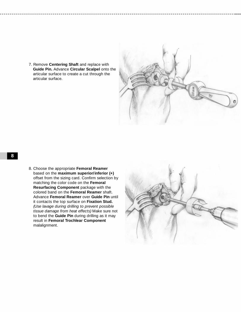
7. Remove Centering Shaft and replace with Guide Pin. Advance Circular Scalpel onto the articular surface to create a cut through the articular surface.
8. Choose the appropriate Femoral Reamer based on the maximum superior/inferior (+)offset from the sizing card. Confirm selection by matching the color code on the Femoral Resurfacing Component package with the colored band on the Femoral Reamer shaft. Advance Femoral Reamer over Guide Pin until it contacts the top surface on Fixation Stud.(Use lavage during drilling to prevent possible tissue damage from heat effects) Make sure not to bend the Guide Pin during drilling as it may result in Femoral Trochlear Component malalignment.

9. Clean taper in Fixation Stud with Taper Cleaner and remove any debris from the surrounding implant bed.
10. Place the Sizing Trial into the defect that matches the offset profile of the chosen Femoral Trochlear Component. Confirm the fit of the Sizing Trial so that all margins are congruent or slightly recessed to the edge of the surrounding articular surface.
9
TR
OC
HL
EA
R C
OM
PO
NE
NT

10
NOTE:Prepare and implant the Patella Componentprior to final placement of the Femoral TrochlearComponent.
11. Prior to placing the Femoral Trochlear Component on the Implant Holder make sure that sufficient suction is present to hold the device on the distal suction cup. Align the Femoral Trochlear Componenton the Implant Holder. Make sure to orient the etch marks on the back of the Femoral Trochlear Component with the etch mark on the handle of the Implant Holder. Align the Femoral Trochlear Component with the appropriate offsets. Insert into taper of Fixation Stud.
12. Firmly mallet the Impactor until the Femoral Trochlear Component is completely seated.

11
PA
TE
LL
A C
OM
PO
NE
NT
Implantation of the HemiCAP® Patella Component
1. Confirm that the patella’s anterior to posterior thickness will accept the Patella Component; typically a 6.5mm reaming depth. With knee at 90 degrees flexion, locate the Alignment Guideso that the pin fits into the Fixation Stud. While observing range of motion, identify target placement of the Patella Component using the pointer on the Alignment Guide to transfer the Fixation Stud’s central axis. (Typically 20 to 30 degrees of flexion). Use slight pressure against the patella so that the pointer on the Alignment Guide creates an indentation on the patella surface.
2. Place the Drill Guide so that its central axis passes through the Alignment Guideindentation created on the patella surface. Drill the Guide Pin through until it engages the opposite cortex of the patella. (It is important to verify that the Drill Guide is seated on the curved surface such that all 4 points of contact are established on the articular surface. Feet on the Drill Guide will typically orient medial and lateral. A normal axis is necessary for proper implant fit).

12
3. Remove the Drill Guide. Advance Circular Scalpel onto the articular surface to create a cut through the articular surface.
4. Place the cannulated Drill over Guide Pin. Verify that the Drill is not bending the Guide Pin and advance until the distal shoulder of Drill is flush to the articular surface. (Use lavage during drilling to prevent possible tissue damage from heat effects). Should the guide pin loosen, use the Drill to re-center the Guide Pin in the pilot hole and advance into bone.
5. Using a powered drill, advance the Patella Centering Shaft over the Guide Pin until it reaches the distal laser marked depth marking.
13mm Drill
Depth
14mmPatella
DrillDepth
13
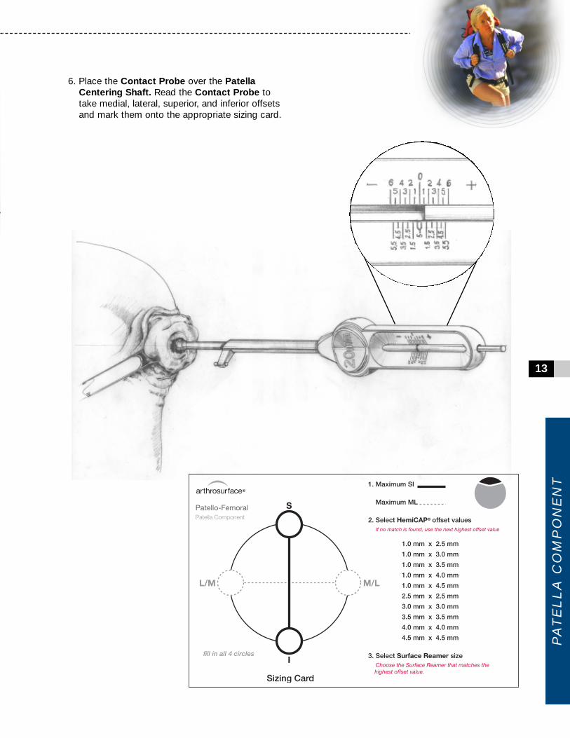
6. Place the Contact Probe over the Patella Centering Shaft. Read the Contact Probe to take medial, lateral, superior, and inferior offsets and mark them onto the appropriate sizing card.
PA
TE
LL
A C
OM
PO
NE
NT

14
7. Select the 2.5mm Patella Reamer. AdvancePatella Reamer over the Patella Centering Shaft until it contacts the blade stop. (Use lavage during drilling to prevent possible tissue damage from heat effects).
8. Load a loop of #2 suture through the appropriately sized Patella Sizing Trialand place into the prepared area. Confirm the fit of the Patella Sizing Trial so that all margins are congruent or slightly recessed to the edge of the surrounding articular surface.
Tip: If using an Anatomic Patella Component: Afterusing a 2.5mm Patellar Reamer, place a 1.0 x 2.5Patella Sizing Trial and confirm fit of medial and lateral margins. Once M/L margins are a congruent fit to the medial/lateral cartilage, select the trial that best fits the superior/inferior margins withoutadditional reaming.
If proud at the M/L margin, drill with the next sizedPatella Reamer and repeat trialing to fit.

9. Apply a small amount of low-viscosity bone cement onto the underside of the Patella Component and quickly place into position.
10. Prior to placing the Patella Component on the Implant Holder make sure that sufficient suction is present to hold the device on the distal suction cup. Align the Patella Component on the Implant Holder. (When using the Anatomic Patella Componentmake sure to align the superior and inferior orientation divots with the superior and inferior poles of the patella).
11. Using the Patella Clamp, place the Anatomic OR Button Contoured Swivel Pin against the Patella Component and the anterior patella surface. Tighten the Patella Clamp until the Patella Component is firmly seated in the prepared socket. Leave the Patella Clamp in place while the bone cement adequately cures.Remove the Patella Clamp and clean out any remaining exposed cement.
15
PA
TE
LL
A C
OM
PO
NE
NT

Prior to placing implant, carefully trim articular cartilage debris around prepared margin. Removebone particles and lavage thoroughly. To ensuremechanical interlock of the Fixation Stud andFemoral Resurfacing Component, carefully cleanFixation Stud taper with provided instruments. Alldrilling or reaming should be done with vigorouslavage to minimize heat effects to adjacent boneand cartilage tissues.
Ensure that care is taken to obtain complete anduniform bone cement coverage at implant site.Unsupported components or unevenly supportedcomponents may result in implant failure.
Accepted practices in post operative care should beused. The patient is to be instructed and monitoredto ensure a reasonable degree of compliance topost operative instructions and activity restrictions.Excessive activity, impact, and weight gain havebeen implicated in the reduction of the benefit andservice life of prosthetic devices.
16
12. Implantation of the Patella Component is complete.
NOTE:Complete implantation of Femoral TrochlearComponent. Refer to page 10.
13. Once implantation of the Femoral and Patella Components is complete, perform a trial rangeof motion. Remove or debride any loose tissuesif necessary. Close utilizing accepted practices.
Warnings
Improper selection, placement, positioning, align-ment, and fixation of the implant components mayreduce the service life of the prosthetic compo-nents. Inadequate preparation and cleaning of theimplant components mating surfaces may result inimproper fixation of the device. Improper handlingof the implants can produce scratches, nicks ordents that may have adverse clinical effects onmating joint surfaces. Do not modify implants. The surgeon shall be thoroughly familiar with theimplants, instruments, and surgical technique priorto performing surgery.
When defining offsets of articular surfaces, careshould be taken to ensure that instruments areproperly aligned and mated with taper in FixationStud. Visually confirm distal tip of Contact Probe ismaking contact on articular surfaces and free fromany soft tissue structures to ensure accuracy. Uselight pressure on Contact Probe to slightly indentarticular surface at each mapping point, ensuringthat the selected implant will be flush or slightlyrecessed with the articular surface.

17
Precautions
HemiCAP® Patello-Femoral Resurfacing implantsare intended to be fitted and installed with theHemiCAP® Patello-Femoral Resurfacing instru-ment set. Use of instruments from other systemsmay result in improper implant selection, fitting,and placement which could result in implant failureor poor clinical outcome. The HemiCAP® instru-ment set should be regularly inspected for anysigns of wear or damage. Do not reuse implants ordisposable instruments.
Possible Adverse Effects
1. Material sensitivity reactions. Implantation of foreign material in tissues can result in histological reactions. Particulate wear debris and mild tissue discoloration from metallic components have been noted in other prosthetic devices constructed of similar materials. Some types of wear debris have been associated with osteolysis and implant loosening.
2. Infection or allergic reaction. 3. Loosening, migration or loss of fixation of
implant. 4. Fretting and crevice corrosion can occur
at the interface between the implant components.
5. Fatigue fracture of the implants as a result of bone resorption around the implant components.
6. Wear and damage to the implant articulating surface.
7. Wear and damage to the adjacent and opposed articular cartilage surfaces or soft tissue support structures.
8. Intraoperative or postoperative bone fracture.9. Postoperative pain or incomplete resolution of
preoperative symptoms.10. Periarticular calcification or ossification, with
or without impediment of joint mobility.11. Incomplete range of motion due to improper
selection or positioning of components.12. Transient nerve palsy.
Sterility
Metallic prosthetic components are sterilized byexposure to gamma irradiation. Non-metallic pros-thetic components are sterilized by gas plasmasterilization. Do not resterilize any components. Donot use components if packaging is opened ordamaged. Do not use components if beyond expiration date.
Caution: United States Federal law restricts thisdevice to sale by or on the order of a physician.

18
Step 6 Sizing Card Femoral Trochlear Component
Step 6 Sizing Card Patella Component

Patello - Femoral Instrumentation
19
INS
TR
UM
EN
TA
TIO
N

This product is covered by one or more of US Patent Nos. 6,520,964; 6,610,067; 6,679,917 and other patents pending.HemiCAP® is a trademark of Arthrosurface®, Inc.
Manufactured by:Arthrosurface,® Inc., 28 Forge Parkway, Franklin, MA 02038tel +1 508 520 3003 • fax +1 508 528 4604
w w w . a r t h r o s u r f a c e . c o m
PN
20
01-3
200
RE
V B
Catalog Number
Articular Component, Trochlear
Articular Component, Patella
Fixation Stud
7000-20007000-20057007-1305
P202-2020P202-2025P202-2030
P202-2520P202-2525P202-2530
P202-3020P202-3025P202-3030P202-3035
P202-3520P202-3525P202-3530
P205-1025P205-1030P205-1035P205-1040P205-1045
P206-0025P206-0030P206-0035P206-0040P206-0045
P085-0017
For all orders call +1-508-520-3003Toll Free call +1-866-261-9294
Instrument Kit, Patello-FemoralRevision Kit, Patello-Femoral2.0 mm Guide Pin (5 Pk)
2.0 mm x 2.0 mm Offset2.0 mm x 2.5 mm Offset2.0 mm x 3.0 mm Offset
2.5 mm x 2.0 mm Offset2.5 mm x 2.5 mm Offset2.5 mm x 3.0 mm Offset
3.0 mm x 2.0 mm Offset3.0 mm x 2.5 mm Offset3.0 mm x 3.0 mm Offset3.0 mm x 3.5 mm Offset
3.5 mm x 2.0 mm Offset3.5 mm x 2.5 mm Offset3.5 mm x 3.0 mm Offset
1.0 mm x 2.5 mm Offset1.0 mm x 3.0 mm Offset1.0 mm x 3.5 mm Offset1.0 mm x 4.0 mm Offset1.0 mm x 4.5 mm Offset
2.5 mm x 2.5 mm Offset3.0 mm x 3.0 mm Offset3.5 mm x 3.5 mm Offset4.0 mm x 4.0 mm Offset4.5 mm x 4.5 mm Offset
Fixation Stud, 8.5 mm x 17 mm
Description
Arthrosurface’s HemiCAP® resurfacing system is also available for the following joints:• Shoulder• Hip• Great Toe• Knee (Available in most International markets via CE mark and as part of a IDE study in the US).
S/I M/L
Anatomic
Button