pathfinder advanced radar ice sounder :paris · johns hopkins university apl 25 june 2008...
TRANSCRIPT

Johns Hopkins University APL
25 June 2008
*University of Kansas
R. Keith Raney, C. Leuschen*, and M. Jose
Pathfinder Advanced Radar
Ice Sounder :PARIS
ESTO-2008

2ESTO-ESTC, June 2008
Agenda
PARIS: Pathfinder Advanced Radar Ice Sounder
2007 Mission to Greenland
The Way Forward

3ESTO-ESTC, June 2008
Objective
Develop techniques to enable and/or to
enhance the visibility of internal layering and
bottom topography of (continental) ice sheets
when probed (sounded) by a high-altitude
radar (from aircraft or spacecraft)

4ESTO-ESTC, June 2008
Perspective
The Major Challenges: Clutter; Weak Signals
Clutter dimensions: Along-track suppression
Across-track suppression
Weak signal mitigation: Innovative radar design
large dynamic range, very low side-lobes,
extreme linearity, generous power
NASA-IIP-supported proof-of-concept system: PARIS
150 MHz (vision: Antarctica; planetary prototype)
High altitude (first successful demonstration, P-3 aircraft)
Prototype for PARIS: D2P radar altimeter(previous NASA IIP project)
5ESTO-ESTC, June 2008
Agenda
PARIS: Pathfinder Advanced Radar Ice Sounder
Along-track clutter suppression
Delay-Doppler processing
Radar design: key features
2007 Mission to Greenland
The Way Forward

6ESTO-ESTC, June 2008
Depth [km]
0
1
2
3
Johns Hopkins University
Applied Physics Laboratory
Dominant features: surface
return and its sidelobes, bottom
return, internal clutter, triple-
bounce from aircraft to surface,
etc; along-track and across-track
clutter sources
dB
Typical B&W radar
sounding profile
*No Doppler processing,
range compression with an
approximate matched filter
> 90
dB
Excellent radar
dynamic range
PARIS Quick-look data*
(Greenland, 07 May 2007)

7ESTO-ESTC, June 2008
Along-Track Clutter Suppression:
Partially-Coherent Doppler
View of along-track plane
s/c
Locus of constant
range delay
Clutter
reflectors
Desired depth
measurement
(A) Zero-
Doppler bin
Internal reflecting surface
(B) Non-zero
Doppler bins
• Transmit “high” PRF (> Nyquist
rate) to unambiguously retain
Doppler spectrum)
• (A) Reflections from nadir will be at
zero-Doppler
• (B) Off-nadir clutter reflections will
have |larger| Doppler frequencies
• Filter data in the Doppler domain to
favor reflections from layers and
depth, and to suppress clutter
Vs/c

8ESTO-ESTC, June 2008
V
Delay-Doppler
processing selects
along-track (small)
footprints,
suppressing off-
nadir clutter
contributions
) ) ) ) ) ) )
Along-Track Clutter Suppression: Doppler
Clutter

9ESTO-ESTC, June 2008
Delay-Doppler TechniqueSpacecraft altimeter example
In situ sounding: dielectrics of ice differ from air => different
velocity of propagation and Doppler scaling in ice.

10ESTO-ESTC, June 2008
Benefits of partially-coherent Doppler processing
Delay-DopplerIncoherent CoherentOriginal data

11ESTO-ESTC, June 2008
Radar sounder architecture (minimize RF operations)
Heavily weighted
waveform is essential
to suppress remote
sidelobes
Sampling rate
<< Nyquist
Dynamic gain control (STC)
Modulate at carrier freq

12ESTO-ESTC, June 2008
Design: isolate aliased (under-sampled) signals
13ESTO-ESTC, June 2008
Agenda
PARIS: Pathfinder Advanced Radar Ice Sounder
Along-track clutter suppression
Delay-Doppler processing
Radar design: key features
2007 Mission to Greenland
Quick-time and initial results
The Way Forward
14ESTO-ESTC, June 2008
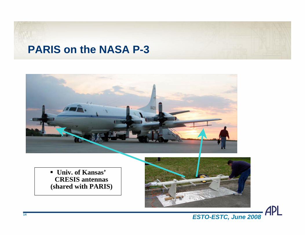
PARIS on the NASA P-3
Univ. of Kansas’CRESIS antennas
(shared with PARIS)

15ESTO-ESTC, June 2008
PARIS: Inside the P-3
PARIS-I Radar in
Operation

16ESTO-ESTC, June 2008
Arctic '07 Mission Tracks
PARIS shared the NASA P-
3 w/ Airborne Topographic
Mapper (ATM)
PARIS operated during
ATM (low-altitude) flights
925 GB of PARIS data
collected over 10 days
High altitude data acquired
04 and 07 May
Sample
Data
07 May

17ESTO-ESTC, June 2008
Raw Data 07 May 2007 14:10:45-14:16:00(sub-sample – first four seconds)
Ice Surface
Ice Surface
Bedrock

18ESTO-ESTC, June 2008
Delay-Doppler (partially-coherent) Sounding
Ice surface
Bed
rock
Focused
Not
well
focused
Not
well
focused
Processing
continues to
progress.
> Range focus of
top and bottom
third of ice
> Along-track
“scalloping”
> Extend to more
difficult clutter-
limited cases
19ESTO-ESTC, June 2008
Agenda
PARIS: Pathfinder Advanced Radar Ice Sounder
Background
Along-track clutter suppression
Radar design: key features
2007 Mission to Greenland
Quick-time and initial results
The Way Forward
Refine along-track processing algorithm
Cross-track clutter suppression
Conclusions

20ESTO-ESTC, June 2008
Cross-Track Clutter Suppression:
Polarization (new concept)
View of cross-track plane
s/c
Locus of constant
range delay
Clutter
reflectors
Desired depth
measurement
(A) Circularly-
polarized
Internal reflecting surface
EX Y
(B) Circulary-
polarized Tx
EX Y
• Transmit circularly polarized (CP)
radiation across the beam
• (A) Reflections (specular) from nadir will
be single-bounce => reversed sense CP
• (B) Off-nadir clutter reflections usually
will be double-bounce => same sense CP
• Different impacts on polarization,
coherence, etc (potential discriminants)

21ESTO-ESTC, June 2008
Why Transmit Circular Polarization?
Single-bounce (specular) reflection always reverses the
sense of the illuminating (circular) polarity
(Linear polarization sense-reversal is not observable)
Most reflections from nadir (and from depth) will be
specular => opposite sense circularly polarized
Specular reflections => high coherence (~ degree of
polarization)
Reflections from clutter almost always will have
different polarization properties

22ESTO-ESTC, June 2008
Dual Hybrid-Polarity Radar Sounder
Transmit Circular Polarization
Receive (coherently) linear (H & V)
Primary data product:
2x2 covariance (or coherency) matrix
of the observed field,
or (equivalently) the 4-element
Stokes vector
Transmitter &
waveform
Antenna
H Rx channel
V Rx channel
90o
H
V
V
H
LNA
LNA
Timing and
control
H processor
V processor
V H
V H
|H|
|V|
HV*H
V*
S1
S2
S3
S4
New degree-of-freedom to realize
cross-track clutter suppression

23ESTO-ESTC, June 2008
Hybrid Polarity
S1 = < |EX|2 + |EY|2 > + 2No
S2 = < |EX|2 - |EY|2 >
S3 = 2 Re < EXEY*>
S4 = - 2 Im < EXEY*>
On Polarimetric Parameters
• Stokes parameters fully characterize the received EM
field => innovation for radar sounder data
• Stokes parameters support parametric discrimination
e.g.: > Measurement of relative (EX :: EY) phase
> Degree of polarization m
= arctan ( S4 / S3 )
m = (S22 + S3
2 + S42) / S1
24ESTO-ESTC, June 2008
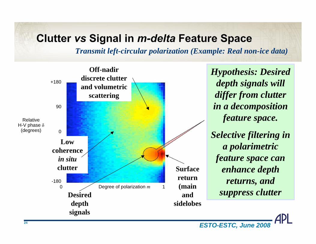
RelativeH-V phase
(degrees) 0
0
-180
+180
1Degree of polarization m
-90
90
Clutter vs Signal in m-delta Feature Space
Hypothesis: Desired
depth signals will
differ from clutter
in a decomposition
feature space.
Selective filtering in
a polarimetric
feature space can
enhance depth
returns, and
suppress clutter
Off-nadir
discrete clutter
and volumetric
scattering
Surface
return
(main
and
sidelobes
Desired
depth
signals
Low
coherence
in situ
clutter
Transmit left-circular polarization (Example: Real non-ice data)

25ESTO-ESTC, June 2008
Clutter Suppression Issues (Recap)
Doppler (along-track): Well established
Proven technique (PARIS, Marsis, etc.)
Ground processing
Optimal performance => must match ice index of refraction
Polarization (across-track): New strategy
Developmental technique: requires proof-of-concept
Ground processing
Optimal performance may imply adaptive selectivity in
response to clutter and depth polarization signatures
A good sounder => a “clean” radar: dynamic range,
linearity, extreme side-lobe control, etc

26ESTO-ESTC, June 2008
Conceptual Flow of Clutter Suppression
Notional
radar
sounder
Presum
(on-
board)
Doppler
selectivity
Enhanced
profile
Stokes
vector
values
Feature
space
Selectivity
decompo-
sition
Along-track
(Doppler)
Across-track
(Polarity)
Range-
Doppler
(FFTs)
Ground processing

27ESTO-ESTC, June 2008
Comments on hybrid-polarity
• Hybrid-polarity is a proven methodology for (compact)
polarimetric SAR (classification by matrix decomposition)
• The cross-track polarimetric method is fully compatible
with along-track enhancement techniques (Doppler and/or
polarimetric) for a radar sounder
• Sidelobes from the surface return can be suppressed if
their polarimetric signature differs from depth signals
• The same technique could help to suppress the triple-
bounce reflection of the aircraft (ideal for a UAV or
airborne radar sounder application)

28ESTO-ESTC, June 2008
Conclusions
Delay-Doppler is successful for suppressing along-
track clutter, enhancing radar sounding signals
High-altitude radar sounding proven to be feasible
PARIS design successfully demonstrates robust (and
generalizable) radar sounder principles
Cross-track clutter suppression by polarimetric
selectivity is a promising (but as yet untested) technique
In practical situations for which clutter vs signal
polarimetric phase distributions are significantly
different, then large SCR gain is likely
Recommend continued development of these themes