paul scherrer institute - istituto nazionale di fisica...
TRANSCRIPT

E. Pedroni CPT - Paul Scherrer Institute - Erice 20 -04-2009
Workshop on HadronBeam Therapy of Cancer
EriceApril 2009
Gantry design and experience at PSIGantry design and experience at PSIGantry design and experience at PSIGantry design and experience at PSI
Eros Pedroni
for the R&D Technology Team
Center for Proton Therapy
Paul Scherrer InstituteVilligen-PSI
SWITZERLAND

E. Pedroni CPT - Paul Scherrer Institute - Erice 20 -04-2009
1. Experience of using GANTRY 1
Gantry 1
• A system designed in 1991 for protons
• Based on the scanning experience with
pion therapy between 1981-1992

E. Pedroni CPT - Paul Scherrer Institute - Erice 20 -04-2009
– Magnetic scanning started before the last bending magnet
• “Upstream scanning” (applied only in the dispersion plane of the beam)
– “Excentric” mounting of patient table on the gantry front wheel (with counter-rotation)
• Reduce gantry radius to 2 m
– Patient couch rotation in the horizontal plane by +,-120°
– 360° axial rotation (a mistake?)
System characteristics of Gantry 1
α rotation
φ rotationβ rotation

E. Pedroni CPT - Paul Scherrer Institute - Erice 20 -04-2009
α+β rotationα rotationBODY HEAD
A very compact system
• Flexibility to apply the beam from any direction
– Patients safety concerns when
treating with beam from below
• patient rescue in case of
motors failures

E. Pedroni CPT - Paul Scherrer Institute - Erice 20 -04-2009
If I could do it again …
• Eccentric mounting as with Gantry 1 (R = 2m)
– But with rotation only on one side (0° 180°) - as with the new Gantry 2
• Floor underneath the patient table
– Room moving with the gantry
– With a counter-rotation
• 2 m compact eccentric gantry Gantry 3 ?

E. Pedroni CPT - Paul Scherrer Institute - Erice 20 -04-2009
X Sweeper magnet 5 ms / step fast
Y Range shifter 30 ms average
– Gaussian pencil beam: 3 mm σ in air
– Cartesian scanning (infinite SSD)
“step and shoot” on a 5 mm grid
– From 1996 until May 2008 the only
scanning gantry in the world
Dynamic pencil beam scanning
Z Patient table 1 cm/s slow
Dose Monitor+Kicker 100 us reaction time
Elements of scanning:

E. Pedroni CPT - Paul Scherrer Institute - Erice 20 -04-2009
SKULL
PELVIS
Clinical use of GANTRY 1
• > 400 patients treated since 1996
• Mainly skull, spinal chord and low pelvis
– Only non moving targets!
– First human patient treated in 1996
– 30 fractions (treatment lasting ~ 6 weeks)
• Capability
– Max 19 patients/day (2-3 per hour)
– 2.8 fields/fractions in average
– Multiple fields delivered without personnel
entering the treatment room
• Weak points of Gantry 1
– Table motion is part of scanning (3. axis)
– Not possible to use collimators
– Not possible to apply repainting

E. Pedroni CPT - Paul Scherrer Institute - Erice 20 -04-2009
Advantages of using scanning
• Automated treatments – all by software
• Avoid the use of individualized hardware
– Save money and personnel to fabricate and mount field-specific equipment
• Apply dose fields in sequences in one go without personnel entering the treatment room
• To reduce treatment time
• Minimal neutron background (for the patient)
– Lower risk of second cancer than scattering (depends on sophistication)
• Important for pediatric treatments
• Less activation of equipment in the nozzle (for the personnel)
• Use of a lower extracted beam intensity
– Less activation of the accelerator
• Minimal simple equipment
– “The (pencil) beam does it for you”

E. Pedroni CPT - Paul Scherrer Institute - Erice 20 -04-2009
Variable modulation of the range
• Avoid unnecessary 100% dose on the healthy tissues
– Especially relevant for large tumors
– Reduce skin dose
E. Pedroni CPT - Paul Scherrer Institute - Erice 20 -04-2009
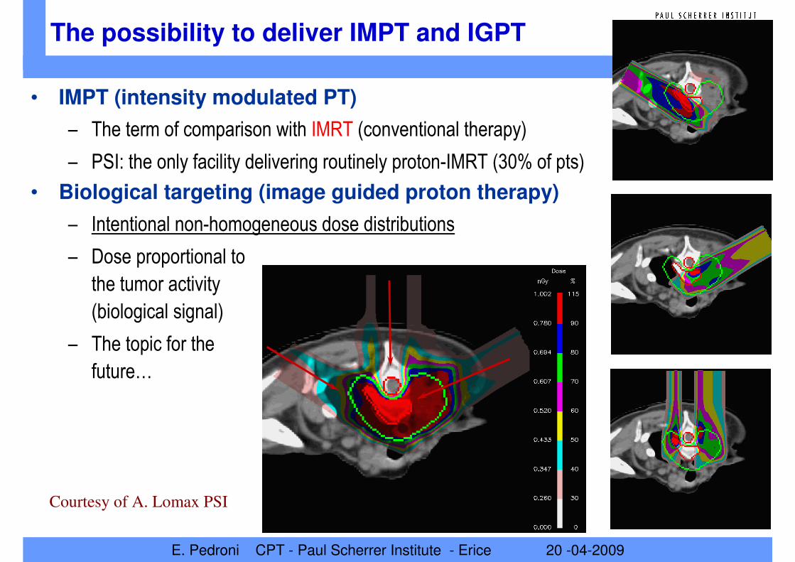
The possibility to deliver IMPT and IGPT
• IMPT (intensity modulated PT)
– The term of comparison with IMRT (conventional therapy)
– PSI: the only facility delivering routinely proton-IMRT (30% of pts)
• Biological targeting (image guided proton therapy)
– Intentional non-homogeneous dose distributions
– Dose proportional to
the tumor activity
(biological signal)
– The topic for the
future…
Courtesy of A. Lomax PSI

E. Pedroni CPT - Paul Scherrer Institute - Erice 20 -04-2009
Major disadvantage: organ motion sensitivity
• Scanning is very sensitive to organ motion errors during beam delivery -> disturbance of the dose homogeneity
– At the moment we can treat at PSI only well immobilized lesions attached to bony
structures
• Tumors in the head, spinal chord and low pelvis
• We accept only movements < + -2 mm
– for treatments with full fractionation!
• Can we overcome this drawback?
– Possible remedies:
• Repainting
• Gating
• Tracking?
– or a combination of those
– …possible points to be developed
with Gantry 2…
The points to learn about

E. Pedroni CPT - Paul Scherrer Institute - Erice 20 -04-2009
2. Next step in 2000 at PSI: the PROSCAN project
• Facility expansion in the NA-Hall
• Problems before 2007
– Parasitic use of the beam in a physics
research environment
• Split and degrade beam from the
(2 mA) 590 MeV main beam
– A multi-user complex facility
• Long shut-down each year
• Beam available only
from May until December
GANTRY 1
OPTIS 1
NEW PROSCAN AREA

E. Pedroni CPT - Paul Scherrer Institute - Erice 20 -04-2009
Layout of the PROSCAN facility
– COMET - new dedicated superconducting cyclotron [ACCEL - H. Blosser design]
– Beam for Gantry 1 all the year through
• patients treatments restarted in February 2007 (no shut-downs since August 07)
– Next generation scanning gantry : Gantry 2 (1. patient planned for 2010))
– Horizontal beam line for OPTIS 2 (1. patients in 2009 – higher priority)
Gantry 2
Gantry 1
OPTIS 2
Exp. Area (PIF)
Disconnect from
Ring cyclotron
Medical cyclotron

E. Pedroni CPT - Paul Scherrer Institute - Erice 20 -04-2009
Dedicated accelerator COMET
• Super-conducting cyclotron
• Requirements for Gantry 2
– Constant energy
– Constant intensity
– Stable beam at the ion source
• Aiming at 2-3% in a few 100 us scale
– Dynamic control of the beam intensity
• With a deflector plate in the first turn
• Beam intensity modulation
– Aiming at 100 µs time scale
– For fast direct control of the dose
delivery while painting dose lines
• For delivering repainted scanning
– See talk of D. Meer tomorrow

E. Pedroni CPT - Paul Scherrer Institute - Erice 20 -04-2009
Energy variations with a degrader
• Fast energy changes with degrader + beam line (GANTRY 2)
• Aiming at 100 ms for a 5 mm proton range step
Carbon wedges
moving against each other
in the beam

E. Pedroni CPT - Paul Scherrer Institute - Erice 20 -04-2009
3. Next generation scanning gantry: Gantry 2
• A tool for developing advanced beam scanning techniques
– Iso-centric layout (~ 4 m radius)
– Double magnetic scanning (parallel) – started upstream of the last 90° bend
– Dynamic beam energy variations with the beam
(gantry beam line with laminated magnets)
• New characteristic
– The new PSI gantry rotates
only on one side
by -30°to 185°
– Flexibility of beam delivery
achieved by rotating the
patient table in the
horizontal plane
– Analogy with longitude and
latitude in world-geography

E. Pedroni CPT - Paul Scherrer Institute - Erice 20 -04-2009
Beam Line
Support
Bearing axle
From -30°
to +180°
Patient table
Room with
fixed floor
ServicesX-ray console
Patient anddoctor
Design started from the patient table…
0°to +180°would have been a better choice (cheaper)…

E. Pedroni CPT - Paul Scherrer Institute - Erice 20 -04-2009
…without loosing any functionality
Sliding CT
(Siemens)
Setup for
treating
moving targets
(relation of the
external
motion
surrogate
with the
internal true
organ motion)

E. Pedroni CPT - Paul Scherrer Institute - Erice 20 -04-2009
– The new idea to use BEV X-rays simultaneously to the proton beam
• …to be investigated
imager
X-ray
BEV X-ray: for QA of moving targets
Hole in the return
yoke of the 90°
bending magnet

E. Pedroni CPT - Paul Scherrer Institute - Erice 20 -04-2009
a) compact gantry b) long throw gantry
SweepersX rays tube
Proton beam
Bending
magnet
nozzle
Yoke hole
Patient
Imager
Sweeper
or
Scatterer
Collimator
• BEV imaging - equivalent to portal imaging with photons
• Very large field-of-view (26 cm x 16 cm)
• not masked by equipment or collimators in the beam path
• QA control of gating and tracking(scanning + pulsed X-rays)
• Single image in the beam direction
BEV X-ray images simultaneous to proton beam
Bend and scan
Scan and bend
E. Pedroni CPT - Paul Scherrer Institute - Erice 20 -04-2009
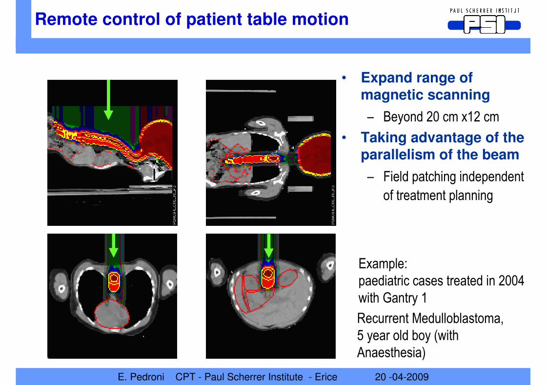
Example:
paediatric cases treated in 2004
with Gantry 1
Recurrent Medulloblastoma,
5 year old boy (with
Anaesthesia)
Remote control of patient table motion
• Expand range of magnetic scanning
– Beyond 20 cm x12 cm
• Taking advantage of the parallelism of the beam
– Field patching independent
of treatment planning
E. Pedroni CPT - Paul Scherrer Institute - Erice 20 -04-2009
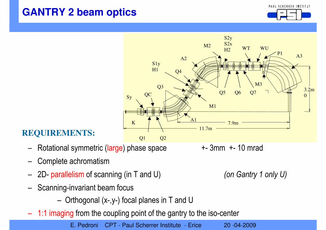
GANTRY 2 beam optics
– Rotational symmetric (large) phase space +- 3mm +- 10 mrad
– Complete achromatism
– 2D- parallelism of scanning (in T and U) (on Gantry 1 only U)
– Scanning-invariant beam focus
– Orthogonal (x-,y-) focal planes in T and U
– 1:1 imaging from the coupling point of the gantry to the iso-center
11.7m
3.2m
0
7.9m
Q1 Q2
QC
Q3
Q4
Q5 Q6 Q7
A1
A2A3
Sy
S1y
H1
S2y
S2x
H2
K
WT WU
M1
M2
M3
P1
REQUIREMENTS:

E. Pedroni CPT - Paul Scherrer Institute - Erice 20 -04-2009
Beam optics confirmed by RAY-TRACING
Dispersive plane
Action of the U-sweeper
Transverse plane
Action of the T-sweeper
Harald Enge raytrace code

E. Pedroni CPT - Paul Scherrer Institute - Erice 20 -04-2009
Advantage of using parallel scanning
• Simplify treatment planning
– Dose homogeneity achieved with standard SOBP rules
• Simplify dosimetry and QA control
– No sensitivity to the distance from the apparent source (small on a gantry)
– Dose value and dose distribution in the patient and in the phantoms are “the same”
• Dose homogeneity preserved
• Easier field patching (expansion of the range for treating long targets)
– Can be done without optimization within treatment planning
• Just exchange magnetic scan position with patient table offset
• Compensators (simulated scattering)
– No dose errors due to inverse R-square effects
• Collimators
– No tapered faces necessary
E. Pedroni CPT - Paul Scherrer Institute - Erice 20 -04-2009
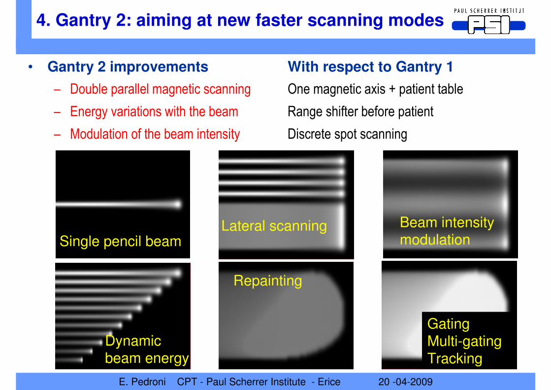
• Gantry 2 improvements With respect to Gantry 1
– Double parallel magnetic scanning One magnetic axis + patient table
– Energy variations with the beam Range shifter before patient
– Modulation of the beam intensity Discrete spot scanning
Single pencil beam
Dynamic beam energy
Repainting
Lateral scanning Beam intensitymodulation
GatingMulti-gating
Tracking
4. Gantry 2: aiming at new faster scanning modes

E. Pedroni CPT - Paul Scherrer Institute - Erice 20 -04-2009
• Painting of lines (contours)
– At max. velocity (~1-2 cm/ms)
– Dose shaping with Beam Intensity Modulation (I.M.)
– < 10 ms per line (10cm + line change)
• Painting of energy iso-layers
– 200 ms per plane (20 lines x 5 mm)
– Change of energy (100 ms - 5mm range)
• Repainting of iso-layers
– 6 s per liter (20 energies at 5mm steps)
• Volumetric repainting capability (aim)
– 10-20 repaintings / liter in 2 minutes
– See talk of David Meer tomorrow
Aiming at the highest scanning speed
E. Pedroni CPT - Paul Scherrer Institute - Erice 20 -04-2009
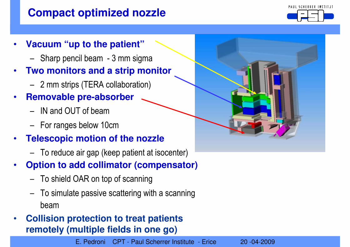
• Vacuum “up to the patient”
– Sharp pencil beam - 3 mm sigma
• Two monitors and a strip monitor
– 2 mm strips (TERA collaboration)
• Removable pre-absorber
– IN and OUT of beam
– For ranges below 10cm
• Telescopic motion of the nozzle
– To reduce air gap (keep patient at isocenter)
• Option to add collimator (compensator)
– To shield OAR on top of scanning
– To simulate passive scattering with a scanning
beam
• Collision protection to treat patients remotely (multiple fields in one go)
Compact optimized nozzle

E. Pedroni CPT - Paul Scherrer Institute - Erice 20 -04-2009
5. Initial commissioning of Gantry 2
• First beam through the new PSI Gantry 2 on May 2008
Only beam line completed

E. Pedroni CPT - Paul Scherrer Institute - Erice 20 -04-2009
Results: pencil beam size (on axis)
• Minimize material in the nozzle for keeping the beam size between 3 and 4 mm sigma at all energies (100-200 MeV)
Adding piece by piece
the materials in the nozzle
To have a sharp lateral fall-off

E. Pedroni CPT - Paul Scherrer Institute - Erice 20 -04-2009
100 MeV
120 MeV
140 MeV
160 MeV
180 MeV
200 MeV
For all energies…
• Parallelism
– Max deviation ~4 mrad

E. Pedroni CPT - Paul Scherrer Institute - Erice 20 -04-2009
Intensity vs. beam energy
• Equalization of the intensity losses of the degrader
– By detuning quadrupoles in the beam line
(gain a factor of 50:1)
– Constant beam intensity at patient location
[0.3 nA]
– With constant extracted
intensity [120 nA]
• Independently of the
energy setting
• Goal
– Reserve the use of the
modulation of the beam
intensity at the ion source
for dynamic dose painting !
Rate Monitor 1
0
100
200
300
400
500
600
100 120 140 160 180 200 220
Energy [MeV]
kH
z down
up

E. Pedroni CPT - Paul Scherrer Institute - Erice 20 -04-2009
• Integral depth dose curves measured with a wide integrating (8-cm diameter) ionizations chamber in a water phantom( + measurements, curves dose model calculation)
– Energy loop Red: up-down Blue: down-up
Taking into account hysteresis effects …

E. Pedroni CPT - Paul Scherrer Institute - Erice 20 -04-2009
• Verification with a stack of 128 10cm-broad ionization chambers
– We can measure the whole range curve on a spot by spot basis (Torino TERA chip)
• Energy of a tunes defined within an hysteresis loop of 100-230 MeV
• Blue curves – up/down down/up – correct order
• Red curves - up/down down/up - wrong order
• We should be able to scanwith energy stepsup-down anddown-up
Range control with an ionization chambers stack
E. Pedroni CPT - Paul Scherrer Institute - Erice 20 -04-2009
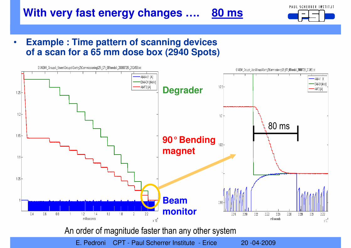
With very fast energy changes …. 80 ms
• Example : Time pattern of scanning devices of a scan for a 65 mm dose box (2940 Spots)
Degrader
90°Bending magnet
Beam monitor
80 ms
An order of magnitude faster than any other system

E. Pedroni CPT - Paul Scherrer Institute - Erice 20 -04-2009
Planned clinical use of Gantry 2
• The new instrument for treating moving targets with IMPT
– With Repainting
– Gating
– Tracking (?) – multiples gates(?)
• New indications
– Moving targets: Liver, Lung, upper GI
– Large Targets:
Craniospinal axis (medulloblastoma),
Central Thorax (Mesothelioma),
Abdominal and Pelvic Lymphnodes
– Small Targets: Integrated boost,
Retinoblastoma, Proton Radiosurgery
(AVM etc)
– Breast cancer
E. Pedroni CPT - Paul Scherrer Institute - Erice 20 -04-2009
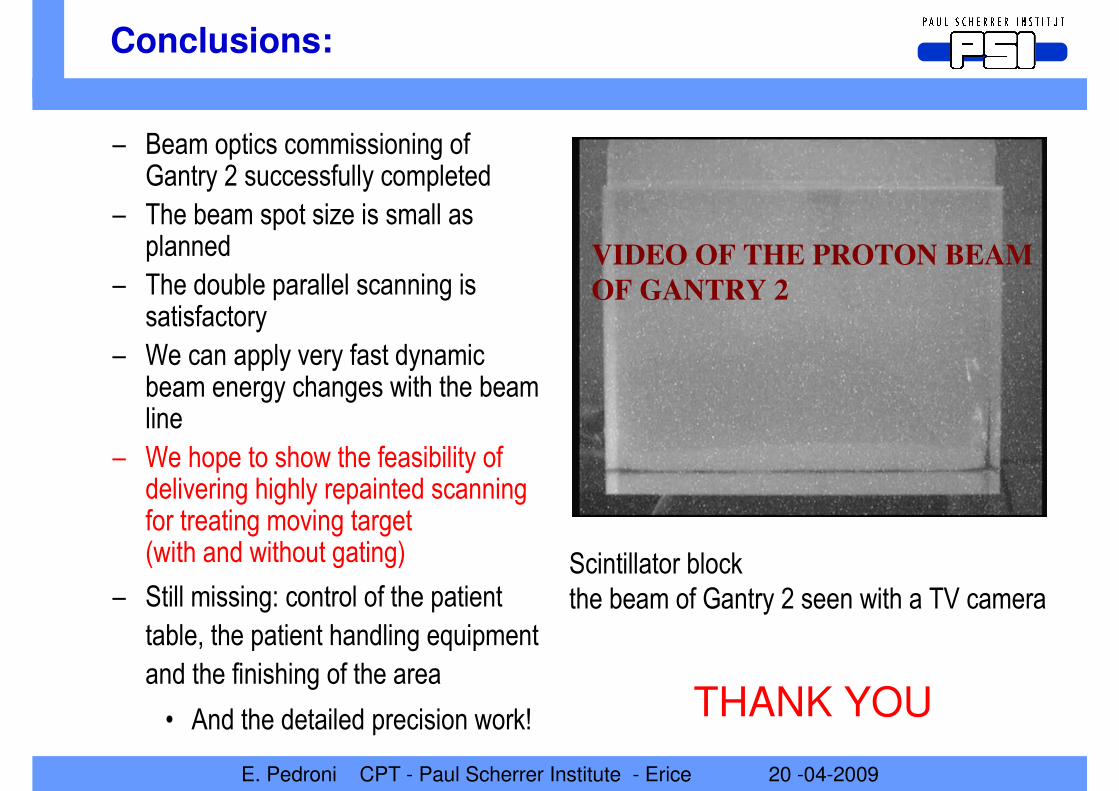
Conclusions:
– Beam optics commissioning of Gantry 2 successfully completed
– The beam spot size is small as planned
– The double parallel scanning is satisfactory
– We can apply very fast dynamic beam energy changes with the beam line
– We hope to show the feasibility of delivering highly repainted scanning for treating moving target (with and without gating)
– Still missing: control of the patient
table, the patient handling equipment
and the finishing of the area
• And the detailed precision work!
Scintillator block
the beam of Gantry 2 seen with a TV camera
THANK YOU
VIDEO OF THE PROTON BEAM
OF GANTRY 2