pcd – 005 polamix - welcome to general photonics · the pcd-005 is a modular polarization...
TRANSCRIPT

PCD – 005 PolaMIX™
All-Fiber Polarization Scrambler Module
with Microprocessor Controller
Operation Manual
July 29, 2011
General Photonics Corp. Ph: (909) 590-5473 5228 Edison Ave. Fax: (909) 902-5536 Chino, CA 91710 USA www.generalphotonics.com
Document #: GP-UM-PCD-005-10 Page 1 of 17
Table of Contents: Section 1. Specifications:.................................................................................................... 3
Section 2. Overview:........................................................................................................... 4
Section 3. Feature Descriptions: ......................................................................................... 5
3.1 Optical Features: ....................................................................................................... 5
3.2 Electrical Features:.................................................................................................... 5
3.2.1 Polarization controller driver board ................................................................... 6
3.2.3 Optional System Bus Adapter Board................................................................. 8
3.2.4 Front panel layout ............................................................................................ 10
3.3 Environmental Requirements: ................................................................................ 10
Section 4. Operation Instruction: ...................................................................................... 11
4.1 Unpacking ............................................................................................................... 11
4.2 Getting Started ........................................................................................................ 11
4.2.1 Setup and operation.......................................................................................... 11
4.4 Remote control and programming: ......................................................................... 13
4.4.1 Remote control connections............................................................................. 13
4.4.2 Remote control programming .......................................................................... 13
4.4.3 LabView Program Interface for PCD-005 Remote Control ............................ 14
Section 5. Technical Support ............................................................................................ 16
Appendix A: PCD-005 Scrambling Frequency Distribution ............................................ 17
Document #: GP-UM-PCD-005-10 Page 2 of 17

Section 1. Specifications: Optical Fiber Input Connector FC/PC or FC/APC Fiber Output Connector FC/PC or FC/APC Insertion Loss 0.05 dB max. at 1550 nm, w/o connectors Center Operation Wavelength Remote or manual selection of 980 nm,
1060 nm, 1310 nm, 1480 nm, 1550 nm, 1600 nm
Operation wavelength range 1 > 100 nm Output degree of polarization 2, 3 < 5% Average PMD < 0.05 ps Intrinsic PDL < 0.05 dB, 0.01 dB typical Return Loss > 65 dB Optical Power Handling > 1000 mW Residual Amplitude Modulation < ±0.01 dB Residual Phase Modulation < 0.1 π Scrambling Frequencies 3 algorithm based on 4 fixed frequencies,
resulting in effective frequency distribution between DC and > 700 kHz
Electrical Power Supply ±12VDC/1A to ±15VDC/1A, +5VDC/0.2A Power Consumption ≤ 20 W Computer Interface RS-232 Environmental and Physical Operation Temperature −5 to 65°C Storage Temperature −20 to 75 °C Dimensions (board only) 220 mm (L) × 100 mm (W) × 30 mm (H) (with shielding box/ front panel) 3U, 8HP standard plug-in module size
235 mm (L) × 130 mm (W) × 40mm (H) Note:
1. Center wavelength ±50 nm. 2. At 500 Hz detection bandwidth 3. Measured from a photodetector at PCD-005 output using a spectrum analyzer.
A polarizer is placed in front of the photodetector to convert polarization modulation to amplitude modulation.
Document #: GP-UM-PCD-005-10 Page 3 of 17
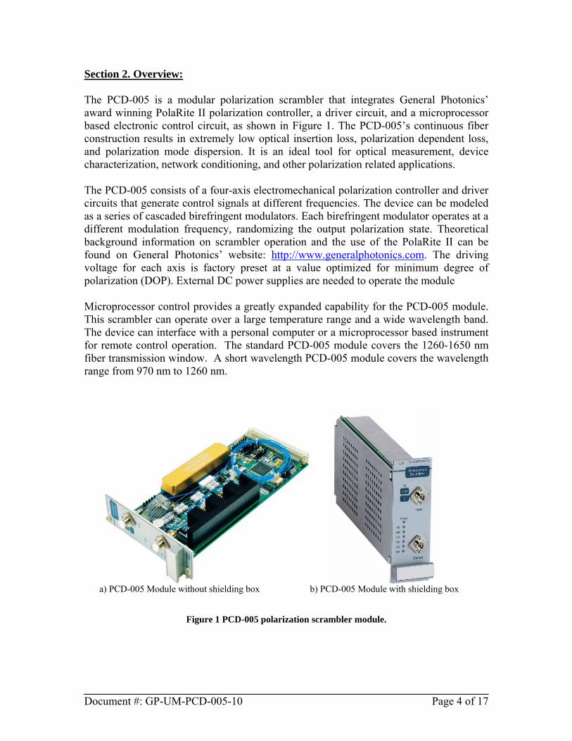
Section 2. Overview: The PCD-005 is a modular polarization scrambler that integrates General Photonics’ award winning PolaRite II polarization controller, a driver circuit, and a microprocessor based electronic control circuit, as shown in Figure 1. The PCD-005’s continuous fiber construction results in extremely low optical insertion loss, polarization dependent loss, and polarization mode dispersion. It is an ideal tool for optical measurement, device characterization, network conditioning, and other polarization related applications. The PCD-005 consists of a four-axis electromechanical polarization controller and driver circuits that generate control signals at different frequencies. The device can be modeled as a series of cascaded birefringent modulators. Each birefringent modulator operates at a different modulation frequency, randomizing the output polarization state. Theoretical background information on scrambler operation and the use of the PolaRite II can be found on General Photonics’ website: http://www.generalphotonics.com. The driving voltage for each axis is factory preset at a value optimized for minimum degree of polarization (DOP). External DC power supplies are needed to operate the module Microprocessor control provides a greatly expanded capability for the PCD-005 module. This scrambler can operate over a large temperature range and a wide wavelength band. The device can interface with a personal computer or a microprocessor based instrument for remote control operation. The standard PCD-005 module covers the 1260-1650 nm fiber transmission window. A short wavelength PCD-005 module covers the wavelength range from 970 nm to 1260 nm.
b) PCD-005 Module with shielding box a) PCD-005 Module without shielding box
Figure 1 PCD-005 polarization scrambler module.
Document #: GP-UM-PCD-005-10 Page 4 of 17

Section 3. Feature Descriptions: 3.1 Optical Features: The PCD-005 module has two optical adapters on the front panel to accommodate the input and output fiber connectors. The input and output ports are interchangeable unless a user specifies special connector combinations. Fiber connectors can be FC/PC, FC/APC, SC/PC, or SC/APC, per customer specification. Before each connection, fiber connectors should be cleaned using industry standard fiber connector cleaning methods. Fiber pigtails should be handled carefully. Excessive force on fiber pigtails may degrade device performance or cause device damage. 3.2 Electrical Features: The PCD-005 can be used as either a plug-in module or as a stand-alone module for laboratory research, experiment, and network applications. The standard version comes with a front panel and shielding box, but OEM versions without the front panel and shielding box are available on request. The PCD-005 module requires a ± 12V/1A DC dual output supply and a +5V DC power supply to operate. The scrambler can operate safely when the voltages of the ± 12V power supply are in the ± 12V to ± 15V DC range. The location and pin assignment of the external power supply connectors will be discussed and illustrated in Section 3.2.1. The scrambling frequencies are factory-set and are not user adjustable. The combined effect of the four specially selected driving frequencies produces a large set of mix frequencies distributed over a large spectral range. A typical distribution of the driving frequencies and their mix products is provided in Appendix A. The board may contain multiple jumpers set at the factory for testing and tuning purposes. Users should not remove these jumpers unless authorized by the manufacturer. The following sections describe the main board and a power supply/communications adapter board.
Document #: GP-UM-PCD-005-10 Page 5 of 17

Document #: GP-UM-PCD-005-10 Page 6 of 17
3.2.1 Polarization controller driver board Figure 2 shows the PCD-005 main board. This board consists of a PolaRite II polarization controller, driving electronics, power and communication connector blocks, and microprocessor and digital control electronics. If the adapter board is not used, the external power supply needs to be connected to the 5-pin JPOW connector jumper block near the upper right hand corner of the board, as shown in Figure 2 and Figure 3. The pin assignment scheme for the JPOW connector is also shown in Figure 2 and Figure 3.
Figure 2 Circuit board layout showing the DC power connector location
Figure 3 Magnified connector area for scrambler board power supply connection. The analog and digital ground lines AGND and DGND should be connected externally at the power supply.
Power Connection Block
AGND AND DGND to BE CONNECTED EXTERNALLY
AGND AND DGND TO BE CONNECTED EXTERNALLY

Figure 4 shows a magnified view of the section of the board containing the power, enable/disable, and wavelength selection status indicator LEDs.
Power LED 980nm LED 1060nm LED 1310nm LED 1480nm LED 1550nm LED 1600nm LED
Scrambler Enable/Disable LED
Figure 4 Magnified section of board showing status indicators There are eight (8) status indicator LEDs. A block of six (6) indicators shows the current wavelength selection. A power indicator LED is located immediately above the wavelength indicator block. The scrambling enable/disable indicator LED is located at the top left of the board. In the wavelength indicator block, the LED corresponding to the current wavelength selection will be on. The default operation wavelength is 1550 nm. The Power LED indicates the external power supply connection status. It turns on if the external power supply is correctly connected. The enable/disable status indicator LED turns on when scrambling is enabled.
Document #: GP-UM-PCD-005-10 Page 7 of 17

3.2.3 Optional System Bus Adapter Board A system bus adapter board (ADB-001, shown in Figure 5) is provided with the PCD-005 module. The ADB-001 provides connections from the power supply socket and RS-232 ports to the 96-pin DIN connector on the PCD-005 board.
Figure 5 ADB-001 System Bus Adapter Board and connector layout.
Board dimensions for the ADB-001: 100 x 50 x 15mm. 10-pin power connector:
A power supply cable is supplied with the ADB-001 board. It connects to the 10-pin power connector on the board. The power connector pins and corresponding cable colors are as follows:
Pin Cable Color Description 1 Black +5 V DC 2 White Digital Ground (DGND) 3 Gray +12 V DC 4 Purple Analog Ground (AGND) 5 Blue −12 V DC 6 Green Analog Ground (AGND) 7 Yellow not used for PCD-005 8 Orange not used for PCD-005 9 Red not used for PCD-005 10 Brown not used for PCD-005
Digital I/O connector (not used for PCD-005)
10-pin power connector
RS 232 connector
96-pin DIN Connector
Document #: GP-UM-PCD-005-10 Page 8 of 17

The analog and digital grounds are connected on the ADB-001 board. When using the ADB-001 with a PCD-005 module, only connections 1-6 are required. The remaining pins/wires can be left unconnected. RS-232 connector: Standard RS-232 connector configuration for communication
between ADB-001 and the serial port on a computer. The RS-232 serial interface port allows the user to remote control the PCD-005. The RS-232 connector on the ADB-001 is a DB9 male connector. Use a straight connection RS-232 cable to connect the ADB-001 to the RS-232 port of a computer. To ensure proper communication, use a serial cable with direct pin-to-pin connected wires (see Figure 6) at both ends of the cable. Note: The ADB-001 transmits through pin 2 and receives through pin 3 of its connector. A PC transmits through pin 3 and receives through pin 2 of its connector.
Figure 6 DB9 Male RS-232 connector pin assignment on ADB-001 board. Digital I/O connector: Not used for PCD-005.
Document #: GP-UM-PCD-005-10 Page 9 of 17

3.2.4 Front panel layout The PCD-005 front panel is shown in Figure 7.
Figure 7 PCD-005 front panel layout Button/LED function descriptions:
Enable: Scrambling enable/disable button Enable LED: Green LED above Enable button, indicating Enable/Disable
status of scrambling function λ: Scrambling center wavelength selection button Module power LED: Red LED above wavelength LED block indicating power
supply connection status Wavelength LEDs: Indicate wavelength selection Input: Input fiber connector adapter Output: Output fiber connector adapter Note that Input/Output fiber interfaces are interchangeable if the two connectors are the same type.
3.3 Environmental Requirements: The PCD-005 is designed for indoor use in an office or laboratory environment. If a PCD-005 scrambler module is placed inside an enclosure, forced-air cooling is strongly recommended for stable DOP performance. The recommended operation temperature range is −5 to 65°C. Outside this temperature range, the output DOP may be higher than the specified value. For best performance, a warm-up period of 5 minutes is recommended before operation. During the warm-up period, the module will operate, with an output DOP of <10%.
Document #: GP-UM-PCD-005-10 Page 10 of 17

Section 4. Operation Instructions: Electrical and optical connections are required during setup of the PCD-005. Follow all necessary safety precautions when making electrical and optical connections. Warning: Never look into the output connector when a light source is connected. THE OUTPUT LIGHT FROM THE PCD-005 MODULE MAY BE HARMFUL TO HUMAN EYES. 4.1 Unpacking Be careful when unpacking the PCD-005 module. Inspect the module or package to check if any components have come loose or disconnected during shipment. If anything unusual is found, please contact General Photonics. The electronic circuit is sensitive to static discharge. For modules with pigtails, avoid applying any force to the pigtails, and do not let any free-drop of fiber connectors occur at any time. 4.2 Getting Started 4.2.1 Setup and operation Follow the steps below to operate the PCD-005. 1. Power connection:
a. For a PCD-005 module without a shielding box, set the power supply to the correct voltages and connect the 5-wire power cable according to Figure 3. For the 5-wire power cable that connects to the main board, the corresponding color codes are:
Black: AGND (±12 V ground) White: +12 V Gray: −12 V Purple: DGND Blue: +5 V
Turn off the power supply before connecting the cable to power jumper connector JPOW as shown in Figure 3. The cable connector is
Document #: GP-UM-PCD-005-10 Page 11 of 17

unidirectional. The ground wires (AGND and DGND) need to be connected at the power supplies. Be careful to avoid damage to fiber pigtails when connecting the ribbon connector.
b. For a PCD-005 with a shielding box, connect the system bus adapter board (ADB-001) to the PCD-005 module, set the power supplies to the correct voltages, and connect the power cable to the ADB-001 board as shown in Figure 5.
2. Turn on the power supply after connecting power cable. The Power LED and 1550 nm LED (Figure 4) will turn on. The default power-up settings are:
Wavelength: 1550 nm Scrambling enable/disable status: OFF.
3. Use the Wavelength Select button (Figure 7) to select the desired operation wavelength. Pressing the Wavelength Select button causes the wavelength setting to cycle sequentially through the 980, 1060, 1310, 1480, 1550, and 1600 nm center wavelengths.
4. Press the Enable button (Figure 7) to enable scrambling. For optimum
performance, a warm-up period of 5 minutes is recommended. The PCD-005 can be used during warm-up, but the DOP may not be optimized.
5. Connect the input and output optical fibers. The output polarization state is
scrambled for low DOP applications and measurements. This step can be performed before enabling the PCD-005 if the optical system following the scrambler allows an unscrambled polarized light input.
6. To disable scrambling, press the enable/disable button. The enable/disable
indicator LED will turn off, and the driver board will go into an idle state. 7. To change to a different wavelength setting, disable the scrambler (make sure the
enable/disable indicator LED is off), and press the Wavelength Select button until the desired wavelength setting is reached. Then press the enable button to enable scrambling at the new wavelength setting.
Document #: GP-UM-PCD-005-10 Page 12 of 17

4.3 Testing and Characterization: The PCD-005 can be serviced only by manufacturer authorized personnel. There are no user serviceable components in this module. Users can test the performance of the PCD-005 with standard polarization analysis instruments or via other established methods. Note that the DOP specification for the PCD-005 is measured at a detector bandwidth of 500 Hz. For high bandwidth detection systems, the DOP can be obtained by averaging data samples within the desired time frame using appropriate sampling systems or instruments. DOP at the polarization scrambler output can be calculated from a simple intensity measurement. In this measurement, a polarizer is placed between the scrambler output fiber and a photodetector with a known detection bandwidth. The maximum and minimum intensities Imax and Imin are then measured from the detector output. The DOP in the measurement bandwidth can be calculated from
%100IIIIDOP
minmax
minmax ×+−
=
Note that Imax and Imin are measured within the desired bandwidth. Different detector bandwidth settings will have different Imax and Imin values. 4.4 Remote control and programming: The PCD-005 can be remote controlled via RS-232. The ADB-001 system adapter board facilitates the remote control connection. 4.4.1 Remote control connections The ADB-001 adapter board has a male connector for an RS-232 cable (Figure 5). Use a straight-wired RS-232 cable to connect the board to the control computer. 4.4.2 Remote control programming General Photonics provides a test program for remote control of the PCD-005. The control software is included on the cd. Note that during control by the test program, the control buttons on the PCD-005 front panel will not respond. To use the front panel buttons, exit the control program. Any program that supports RS-232 communication can be used to send ASCII commands to the PCD-005 for remote control. For users who wish to write their own control programs, the following steps and commands are recommended for remote operation of the PCD-005 using the RS 232 communication port.
Document #: GP-UM-PCD-005-10 Page 13 of 17

1. Connect PCD-005 to PC using a straight-wired RS-232 cable (DB-9 female to female).
2. Referring to Table 1, send a command string to the PCD-005 through the RS-232 port. There are many programming languages that support serial communications, including Visual Basic, LabView and C.
RS-232 command notes:
1. RS-232 port uses asynchronous framing, 8 data bits, no parity bit, and 1 stop bit. 2. RS-232 baud rate: 9600 bps. 3. Only one command is allowed in each command string.
Table 1 PCD-005 remote control command list
Command Function
*DIS# Disable scrambling *ENA# Enable scrambling
*WAV 980# Set wavelength to 980 nm *WAV 1060# Set wavelength to 1060 nm *WAV 1310# Set wavelength to 1310 nm *WAV 1480# Set wavelength to 1480 nm *WAV 1550# Set wavelength to 1550 nm *WAV 1600# Set wavelength to 1600 nm
*WAV? Query current wavelength setting 4.4.3 LabView Program Interface for PCD-005 Remote Control A remote control program is provided for computer control of the PCD-005 via RS-232. This control program is an executable file generated using the LabView developing environment. Before running the control program, the LabVIEW Run-Time Engine v.8.2 and the VISA driver must be installed. Run the following files on the cd to install the drivers:
LVRunTimeEng_8.2 Visa400runtime.exe
Once the drivers are installed, the control program PCD_REMOTE.exe can be run. Figure C1 shows the screen layout of the PCD_REMOTE control program. The program auto-senses the COM port being used.
Document #: GP-UM-PCD-005-10 Page 14 of 17

Figure C1 Remote control program interface
Port Configuration: Displays the selected port for the RS-232. If the selected port and the actual connection do not match, the program cannot communicate with the module. The program should auto-sense the correct port when it is started, but if communication cannot be established, the user can check the actual connection port from the Device Manager and change the port selection from the Port Configuration pull-down menu to match. Note that the port number cannot be changed while the program is executing. Stop the program first and choose the correct port if necessary. Notes: ASRL1:INSTR is the same as COM1 for RS-232.
Wavelength: Pull-down menu for setting operation wavelength. Options are 980, 1060, 1310, 1480, 1550, and 1600. Scrambling must be disabled before setting wavelength.
START: Enables (indicator green) or disables (indicator dark) scrambling.
Document #: GP-UM-PCD-005-10 Page 15 of 17
Section 5. Technical Support General Photonics is committed to high quality standards and customer satisfaction. For questions or suggestions regarding the PCD-005, please feel free to contact General Photonics Corporation at (909)-590-5473 (telephone) or (909)-902-5536 (fax), or by e-mail at [email protected]. General Photonics will respond to all customer questions within 24 hours during regular business hours. General Photonics can be reached by mail at: General Photonics 5228 Edison Avenue Chino, California 91710 USA
Document #: GP-UM-PCD-005-10 Page 16 of 17

Appendix A: PCD-005 Scrambling Frequency Distribution The multi-stage birefringence modulation results in a polarization modulation over a wide spectrum of beat frequencies. The frequency distribution for a typical PCD-005 module is shown in Figure A1. The data was measured by passing light through a polarizer to a photodetector, with the detector output fed to an electrical spectrum analyzer. The frequency distribution is quite uniform to around the 700 KHz range, and then gradually decreases in strength up to about 2 MHz. The frequency distribution may differ slightly in different modules due to different frequency settings and input polarization states.
-80
-60
-40
-20
0
Out
put L
evel
(dB
m)
2.01.51.00.50.0
Frequency (MHz)
4-Section Scrambler
Figure A1. PCD-005 scrambling frequency distribution measured
through a polarizer between 0 ~ 2 MHz.
Document #: GP-UM-PCD-005-10 Page 17 of 17