pcx anolog series manual - soundstream | mobile car … full range.pdfby using the bass boost...
TRANSCRIPT

PCX2.180 / 2.270/ 2.350 / 2.440 / 2.540 / 2.700PCX4.240 / 4.360 / 4.540
PCX5.600
OWNER'S MANUAL


TROUBLE SHOOTING.......................................................... 13
ADJUSTING & TUNING........................................................ 12
PLANNING & MOUNTING YOUR SYSTEM................................ 9 ~10
WIRING DIAGRAM.............................................................. 11
CONTROLS & FUNCTIONS...................................................
FEATURES & SPECIFICATIONS.............................................
TABLE OF CONTENTS
INTRODUCTION................................................................. 2
3
4 ~ 8
TAB
LE
OF
CON
TEN
TS
INTRODUCTION
Amplifier's provide high-performance sound reinforcement for you'r mobile audio equipment. The Multi-Mode bridging capabilities allow flexibility in hosting several different speaker configurations.
To achieve optimum performance, it is highly recommended that you read this Owners Manual before beginning installation.
INTR
OD
UCTI
ON
2

FEATURES
SPECIFICATIONS
FEA
TUR
ES
& S
PE
CIFI
CATI
ON
S
PCX2.180
PCX2.270
PCX2.350
PCX2.440
PCX2.540
PCX2.700
PCX4.240
PCX4.360
PCX4.540
PCX5.600
2
2
2
2
2
2
4
4
4
5
60W x 2CH
80W x 2CH
110W x 2CH
150W x 2CH
180W x 2CH
220W x 2CH
40W x 4CH
60W x 4CH
80W x 4CH
60W x 4CH +
175W x 1CH
90W x 2CH
135W x 2CH
175W x 2CH
220W x 2CH
270W x 2CH
350W x 2CH
60W x 4CH
90W x 4CH
135W x 4CH
90W x 4CH +
240W x 1CH
180W x 1CH
175W x 1CH
350W x 1CH
440W x 1CH
540W x 1CH
700W x 1CH
120W x 2CH
180W x 2CH
270W x 2CH
180W x 2CH +
240W x 1CH
11.8"x2.5"x9.9"
13.8"x2.5"x9.9"
15.7"x2.5"x9.9"
17.7"x2.5"x9.9"
21.7"x2.5"x9.9"
23.6"x2.5"x9.9"
14.9"x2.5"x9.9"
16.5"x2.5"x9.9"
18.9"x2.5"x9.9"
25.2."x2.5"x9.9"
MODEL RMS @ 4 OHM @ 2 OHM @ 4 OHM FUSES DIMENSIONSCHANNEL
IDI (Intelligent Distress Indicator)gives a visual
indication of the amplifier's protection status
Fully regulated MOSFET power supply
PWM circuitry
Tri-guard amplifier protection
Platinum RCA inputs and outputs
Bi-linear selectable crossovers for inputs and outputs (Hi/Full/Low)
Continuously variable high and low-pass crossovers
Subwoofer equalizer control switch
Viable phase shift control (0 - 180 degree)
OEM floating ground input
Platinum 4-gauge power connectors
Tri-mode operation
Includes remote bass boost control (PCX2.350/2.440/2.540/2.700/5.600)
30A X 1
40A X 1
20A X 2
30A X 2
25A X 3
30A X 3
20A X 2
25A X 2
20A X 3
40A X 2
3
(BRIDGE)

REMOTE INPUTS LINE OUT
CROSSOVER
HIGH FULLLOW LOW
FULL HIGH
POWER
PROTECTION
BASSBOOST
0
LEVEL
MIN MAX
LOWPASS
50 150(Hz)
HIGHPASS
50 500(Hz)
HIGHPASS
50 500(Hz)
LOWPASS
50 150(Hz)
LEVEL
MIN MAX
BASSBOOST
0
CROSSOVER
PHASE
0 180
PHASE
0 180
CH3/4 CH1/2
4 Channel High Power Mosfet Amplifier4 Channel High Power Mosfet Amplifier
PicassoPicasso
CH3
CH4
CH1
CH2
CH1
CH2
FUSES CH2 CH3 CH4CH1SPEAKER
POWER
CH2 CH3 CH4CH1
B/D B/DBATT REM GND
PicassoPicasso
2 Channel High Power Mosfet Amplifier2 Channel High Power Mosfet Amplifier
POWER
BATT REM GND
L R RL
SPEAKER
PicassoPicasso
FUSES
B/D
HIGHPASS
50 500(Hz)
CROSSOVER
FULLHIGH
LOW
BASSBOOST
0 50 MIN MAX
LOWPASS
LEVEL
(Hz)
INPUTS
L
LINE OUT
R
REMOTE
150
PHASE
0 180
2 Channel High Power Mosfet Amplifier2 Channel High Power Mosfet Amplifier
POWER
PROTECTION
PicassoPicasso
PCX2.180 / 2.270 / 2.350 / 2.440 / 2.540 / 2.700
PCX4.240 / 4.360 / 4.540
PCX2.180 : 30A X 1PCX2.270 : 40A X 1PCX2.350 : 20A X 2PCX2.440 : 30A X 2PCX2.540 : 25A X 3PCX2.700 : 30A X 3
CON
TRO
LS
& F
UNCT
ION
S
10 11 12
4
Controls & Functions
PCX4.240 : 20A X 2PCX4.360 : 25A X 2PCX4.540 : 20A X 3
15 24 36 14 7 8 9
13
fuse
1
5 2
43
614 7 8 9526
134
10 11 12 13
fuse

FUSES
CH2 CH3 CH4 CH5
CH2 CH3 CH4 CH5
CH1
CH1
B/D
SPEAKERPOWER
BATT REM GNDB/D
PicassoPicasso
PWR
PROT
INPUTS INPUTS INPUTSHIGHPASS
50 500(Hz)
LEVEL
MIN MAX
HIGHPASS
50 500(Hz)
MIN MAXRCA
LEVEL
MIN MAX
FREQ
25 160
LOWPASS
50 150
LEVEL
MODE
MIN MAX
(Hz) (Hz)
0
BASSBOOST
L
RPHASE
0 180
LEVEL1/21/2CH 3/43/4CH 55CH
REMOTE
5 Channel High Power Mosfet Amplifier5 Channel High Power Mosfet Amplifier
PicassoPicasso
CH1
CH2
CH3
CH4
CH5
CH5
PCX5.600
Controls & Functions
CON
TRO
LS
& F
UNCT
ION
S
5
10 11 12
5 2
14
9
13
fuse
PCX5.600 : 40A X 2
7 7 75
4111 15
1
3

PHASE SHIFT SWITCH (0 AND 180 DEGREES): Allows you to change the phase of your subwoofer from 0 to 180 degrees to help compensate for timing differences between drivers.
1. Input Level Adjustment
This control adjusts the amplifier's input sensitivity. Input sensitivity is variable from 200 Millivolts to 8 volts. Clockwise increases sensitivity. Counterclockwise decreases sensitivity. The amplifier can be driven to full power with a wide range of signal levels.A lower signal level will require increased sensitivity for full power. A higher signal level will require decreased sensitivity. Avoid setting sensitivity lower than necessary as this would introduce unwanted distortion.
2. Low Pass Filter Control
This control is used to set the desired low pass frequency (50 ~ 150HZ).The filter acts to cut-off frequencies above the set-point. In general, the selected frequency should closely match the resonant frequency of the speaker box.
3. Bass Boost Control
By using the bass boost function, bass notes at 35Hz - 80Hz are emphasized as much as 18dB.
4. Phase Shift Control
LEVEL
MIN MAX
LOWPASS
50 150(Hz)
BASSBOOST
0 +18
PHASE
180
Controls & Functions
0
6
CON
TRO
LS
& F
UNCT
ION
S
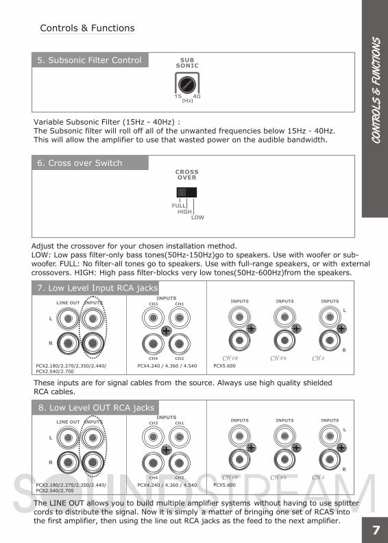
5. Subsonic Filter Control
Variable Subsonic Filter (15Hz - 40Hz) : The Subsonic filter will roll off all of the unwanted frequencies below 15Hz - 40Hz. This will allow the amplifier to use that wasted power on the audible bandwidth.
6. Cross over Switch
7. Low Level Input RCA jacks
These inputs are for signal cables from the source. Always use high quality shielded RCA cables.
8. Low Level OUT RCA jacks
The LINE OUT allows you to build multiple amplifier systems without having to use splitter cords to distribute the signal. Now it is simply a matter of bringing one set of RCAS into the first amplifier, then using the line out RCA jacks as the feed to the next amplifier.
SUBSONIC
15 40(Hz)
INPUTS
L
LINE OUT
R
Controls & Functions
CROSSOVER
FULLHIGH
LOW
Adjust the crossover for your chosen installation method.LOW: Low pass filter-only bass tones(50Hz-150Hz)go to speakers. Use with woofer or sub-woofer. FULL: No filter-all tones go to speakers. Use with full-range speakers, or with external crossovers. HIGH: High pass filter-blocks very low tones(50Hz-600Hz)from the speakers.
INPUTSCH3
CH4
CH1
CH2
INPUTS INPUTS INPUTS
L
R
1/21/2CH 3/43/4CH 55CHPCX5.600PCX4.240 / 4.360 / 4.540PCX2.180/2.270/2.350/2.440/
PCX2.540/2.700
INPUTS
L
LINE OUT
R
INPUTSCH3
CH4
CH1
CH2
INPUTS INPUTS INPUTS
L
R
1/21/2CH 3/43/4CH 55CHPCX5.600PCX4.240 / 4.360 / 4.540PCX2.180/2.270/2.350/2.440/
PCX2.540/2.700
7
CON
TRO
LS
& F
UNCT
ION
S

8
CON
TRO
LS
& F
UNCT
ION
S
Controls & Functions
10. B+ Terminal (Battery positive)
Due to the power requirements of the Amplifier, this connection should be made directly to the positive(+) terminal of battery. For safety measure, install an in-line fuse Holder (not included) as close to the battery positive(+) terminal as possible with an ampere rating ; not to exceed total value of fuses in Amp.
9. LED Indicator
PWR(Power): This GREEN LED will illuminate when the amplifier is turned "ON". If it fails to illuminate, check the power connections to the Amplifier and fuses.
PROT(Protection): The amplifier protection circuitry will disable the amplifier if input overload, short circuit or extremely high temperature conditions are detected. When the protection mode is in operation, the LED indicator on the side panel will be illuminated, indicating the amplifier has gone into a self-preservation mode.
If you observe that the Protection LED is lit, please check the system carefully to determine what has caused the protection circuit to engage. The amplifier can be reset by turning the remote power off and then on again. If the amplifier shut down due to a thermal overload condition, please allow it to cool down before restarting. If the amplifier shut down because of an input overload or short circuit, be sure to repair these conditions before attempting to power up the amplifier again.
11. Remote Power On
PWR
PROT
POWER
BATT REM GND
POWER
BATT REM GND
PCX5.600
PCX4.240 / 4.360 / 4.540PCX2.180/2.270/2.350/2.440/PCX2.540/2.700
POWER
BATT REM GND
POWER
BATT REM GND
PCX5.600
PCX4.240 / 4.360 / 4.540PCX2.180/2.270/2.350/2.440/PCX2.540/2.700
CH2 CH3 CH4 CH5
CH2 CH3 CH4 CH5
CH1
CH1
B/D
SPEAKER
B/D
CH2 CH3 CH4CH1SPEAKER
CH2 CH3 CH4CH1
B/D B/D
L R RL
SPEAKER
B/D
9
CON
TRO
LS
& F
UNCT
ION
S
Controls & Functions
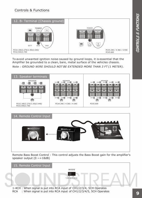
To avoid unwanted ignition noise caused by ground loops, it is essential that the Amplifier be grounded to a clean, bare, metal surface of the vehicles chassis.
Note : GROUND WIRE SHOULD NOT BE EXTENDED MORE THAN 3 FT (1 METER).
13. Speaker terminals
14. Remote Control Input
Remote Bass Boost Control : This control adjusts the Bass Boost gain for the amplifier's speaker output (0 ~+18dB)
12. B- Terminal (Chassis ground)
15. Remote Control Input
1-4CH : When signal is put into RCA input of CH1/2/3/4, 5CH OperatesRCA : When signal is put into RCA input of CH1/2/3/4/5, 5CH Operates
MODE
RCA
POWER
BATT REM GND
POWER
BATT REM GND
PCX5.600
PCX4.240 / 4.360 / 4.540PCX2.180/2.270/2.350/2.440/PCX2.540/2.700
PCX5.600PCX4.240 / 4.360 / 4.540PCX2.180/2.270/2.350/2.440/PCX2.540/2.700

10
Planning and Mounting Your System
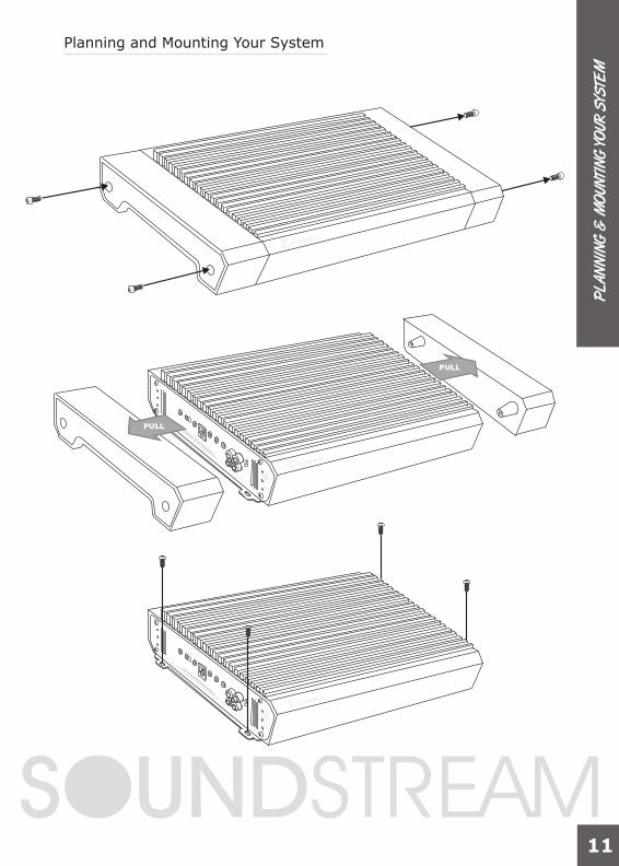
The mounting position of your Amplifier will have a great effect on its ability to dissipate the heat generated during normal operation.Under normal conditions, the heatsink will dissipate sufficient heat to avoid thermal shutdown. However please do not install the amplifier in a wooden box or similar device as this will prevent heat dissipation into the atmosphere.
Temperatures in car trunks have been measured as high as (155'F) in the summer time. since the thermal shut-down point for the amplifier is (158'F) it is easy to see that it must be mounted for maximum cooling capability. To achieve maximum advantage of convection air flow in an enclosed trunk, mount the amplifier in a horizontal position.
Cooling requirements are considerably relaxed when mounting inside the passenger compartment since the driver will not often allow temperatures to reach a critical point. Floor mounting under the seat is usually satisfactory as long as there is at least 1 inch of clearance (2.54 cm) above the Amplifier's fins for ventilation.
A. Select a suitable location that is convenient for mounting, is accessible for wiring. And has ample room for air circulation and cooling.B. Use the amplifier as a template to mark the mounting holes. Remove the Amplifier and drill holes. Use extreme caution, inspect underneath surface before drilling!C. Secure the Amplifier using the screws provided.
endcap Heat sink endcap
PL
AN
NIN
G &
MO
UNTI
NG
YO
UR S
YSTE
M
11
PL
AN
NIN
G &
MO
UNTI
NG
YO
UR S
YSTE
M
Planning and Mounting Your System
PULL
PULL
12
WIR
ING
DIA
GR
AM
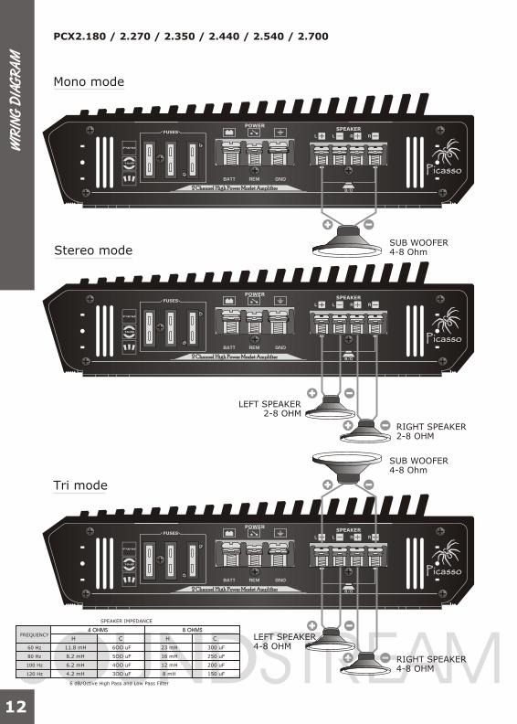
Mono mode
Tri mode
2 Channel High Power Mosfet Amplifier2 Channel High Power Mosfet Amplifier
POWER
BATT REM GND
L R RL
SPEAKER
PicassoPicasso
FUSES
B/D
2 Channel High Power Mosfet Amplifier2 Channel High Power Mosfet Amplifier
POWER
BATT REM GND
L R RL
SPEAKER
PicassoPicasso
FUSES
B/D
SUB WOOFER4-8 Ohm
PCX2.180 / 2.270 / 2.350 / 2.440 / 2.540 / 2.700
RIGHT SPEAKER4-8 OHM
LEFT SPEAKER
Stereo mode
2 Channel High Power Mosfet Amplifier2 Channel High Power Mosfet Amplifier
POWER
BATT REM GND
L R RL
SPEAKER
PicassoPicasso
FUSES
B/D
RIGHT SPEAKER2-8 OHM
LEFT SPEAKER2-8 OHM
4-8 OHM
SUB WOOFER4-8 Ohm
FREQUENCY
60 Hz 11.8 mH 6OO uF
5OO uF
4OO uF
3OO uF
23 mH
16 mH
12 mH
8 mH
300 uF
250 uF
200 uF
150 uF
8.2 mH
6.2 mH
4.2 mH
H
SPEAKER IMPEDANCE
6 dB/Octive High Pass and Low Pass Filter
HC C
80 Hz
100 Hz
120 Hz

FUSES CH2 CH3 CH4CH1SPEAKER
POWER
CH2 CH3 CH4CH1
B/D B/DBATT REM GND
PicassoPicasso
FUSES CH2 CH3 CH4CH1SPEAKER
POWER
CH2 CH3 CH4CH1
B/D B/DBATT REM GND
PicassoPicasso
FUSES CH2 CH3 CH4CH1SPEAKER
POWER
CH2 CH3 CH4CH1
B/D B/DBATT REM GND
PicassoPicasso
13
WIR
ING
DIA
GR
AM
2Channel mode
PCX4.240 / 4.360 / 4.540
3Channel mode
4Channel mode
SUB WOOFER4-8 OHM
SUB WOOFER4-8 OHM
SUB WOOFER4-8 OHM
CH 42-8 OHM
CH 32-8 OHM
CH 4CH 22-8 OHM2-8 OHM
CH 3CH 12-8 OHM2-8 OHMFREQUENCY
60 Hz 11.8 mH 6OO uF
5OO uF
4OO uF
3OO uF
23 mH
16 mH
12 mH
8 mH
300 uF
250 uF
200 uF
150 uF
8.2 mH
6.2 mH
4.2 mH
H
SPEAKER IMPEDANCE
6 dB/Octive High Pass and Low Pass Filter
HC C
80 Hz
100 Hz
120 Hz
FUSES
CH2 CH3 CH4 CH5
CH2 CH3 CH4 CH5
CH1
CH1
B/D
SPEAKERPOWER
BATT REM GNDB/D
PicassoPicasso
FUSES
CH2 CH3 CH4 CH5
CH2 CH3 CH4 CH5
CH1
CH1
B/D
SPEAKERPOWER
BATT REM GNDB/D
PicassoPicasso
FUSES
CH2 CH3 CH4 CH5
CH2 CH3 CH4 CH5
CH1
CH1
B/D
SPEAKERPOWER
BATT REM GNDB/D
PicassoPicasso
14
WIR
ING
DIA
GR
AM
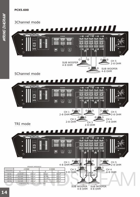
PCX5.600
3Channel mode
5Channel mode
TRI mode
SUB WOOFER4-8 OHM
SUB WOOFER4-8 OHM
CH 5
CH 5
2-8 OHM
2-8 OHM
CH 4
CH 4
2-8 OHM
4-8 OHM
CH 52-8 OHM
CH 2
CH 2
2-8 OHM
4-8 OHM
CH 1
CH 1
2-8 OHM
4-8 OHM
CH 3
CH 3
2-8 OHM
4-8 OHM
SUB WOOFER4-8 OHM
SUB WOOFER4-8 OHM
FREQUENCY
60 Hz 11.8 mH 6OO uF
5OO uF
4OO uF
3OO uF
23 mH
16 mH
12 mH
8 mH
300 uF
250 uF
200 uF
150 uF
8.2 mH
6.2 mH
4.2 mH
H
SPEAKER IMPEDANCE
6 dB/Octive High Pass and Low Pass Filter
HC C
80 Hz
100 Hz
120 Hz
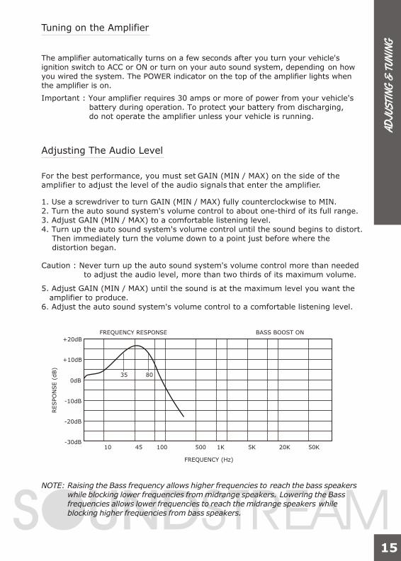
Tuning on the Amplifier
Adjusting The Audio Level
The amplifier automatically turns on a few seconds after you turn your vehicle's ignition switch to ACC or ON or turn on your auto sound system, depending on howyou wired the system. The POWER indicator on the top of the amplifier lights whenthe amplifier is on.
Important : Your amplifier requires 30 amps or more of power from your vehicle's battery during operation. To protect your battery from discharging, do not operate the amplifier unless your vehicle is running.
FREQUENCY (Hz)
10-30dB
-20dB
-10dB
0dB
+10dB
+20dB FREQUENCY RESPONSE
RESPO
NSE (
dB)
BASS BOOST ON
45
35 80
100 500 1K 5K 20K 50K
NOTE: Raising the Bass frequency allows higher frequencies to reach the bass speakers while blocking lower frequencies from midrange speakers. Lowering the Bass frequencies allows lower frequencies to reach the midrange speakers while blocking higher frequencies from bass speakers.
For the best performance, you must set GAIN (MIN / MAX) on the side of the amplifier to adjust the level of the audio signals that enter the amplifier.
1. Use a screwdriver to turn GAIN (MIN / MAX) fully counterclockwise to MIN.2. Turn the auto sound system's volume control to about one-third of its full range.3. Adjust GAIN (MIN / MAX) to a comfortable listening level.4. Turn up the auto sound system's volume control until the sound begins to distort. Then immediately turn the volume down to a point just before where the distortion began.
Caution : Never turn up the auto sound system's volume control more than needed to adjust the audio level, more than two thirds of its maximum volume.
5. Adjust GAIN (MIN / MAX) until the sound is at the maximum level you want the amplifier to produce.6. Adjust the auto sound system's volume control to a comfortable listening level.
15
AD
JUS
TIN
G &
TUN
ING
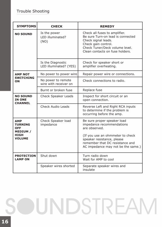
Trouble Shooting
SYMPTOMS
NO SOUND
AMP NOTSWITCHING ON
NO SOUNDIN ONE CHANNEL
AMPTURNINGOFFMEDIUM / HIGHVOLUME
PROTECTIONLAMP ON
Is the power
Is the Diagnostic LED illuminated? (YES)
No power to power wire Repair power wire or connections.
No power to remote wire with receiver on
Check connections to radio.
Burnt or broken fuse
Check Speaker Leads Inspect for short circuit or an open connection.
Reverse Left and Right RCA inputs to determine if the problem is occurring before the amp.
Be sure proper speaker load impedance recommendations are observed.
(If you use an ohmmeter to check speaker resistance, please remember that DC resistance and AC impedance may not be the same.)
Check Audio Leads
Check Speaker load impedance
Shut down Turn radio down Wait for AMP to cool
Speaker wires shorted Separate speaker wires and insulate
Check for speaker short or amplifier overheating.
Check all fuses to amplifier. Be sure Turn-on lead is connected Check signal leads. Check gain control. Check Tuner/Deck volume level. Clean contacts on fuse holders.
LED illuminated?
(NO)
CHECK REMEDY
Replace fuse
TRO
UBL
E S
HO
OTI
NG
16


www.soundstream.com