pd6830 explosion-proof pulse input rate · pdf filepd6830 pulse input rate/totalizer...
TRANSCRIPT

PRECISION DIGITAL CORPORATION 89 October Hill Road • Holliston MA 01746 USA Tel (800) 343-1001 • Fax (508) 655-8990
www.predig.com
PD6830 EXPLOSION-PROOF PULSE INPUT RATE/TOTALIZER
Pulse, Open Collector, NPN, PNP, TTL, Switch Contact, Sine Wave (Coil), Square Wave, Opto-Isolated Inputs
Modern, Sleek and Practical Enclosure Isolated 4-20 mA Output for Either Rate or Total 5-Digit Rate, 0.7" (17.8 mm) 7 Alphanumeric Character Total/Tag, 0.4" (10.2 mm) 7-Digit Totalizer SafeTouch® Through-Glass Button Programming Battery, DC, or Output Loop-Powered Models Gate Function for Rate Display of Slow Pulse Rates K-Factor, Scaling, or Live Input Calibration 32-Point Linearization Password Protection Backlight Standard on All Models Explosion-Proof, IP68, NEMA 4X Enclosure Operates from -40 to 75°C (-20 to 75°C on Battery Models)
®

PD6830 Pulse Input Rate/Totalizer Instruction Manual
2
Disclaimer The information contained in this document is subject to change without notice. Precision Digital makes no representations or warranties with respect to the contents hereof; and specifically disclaims any implied warranties of merchantability or fitness for a particular purpose.
!
CAUTION: Read complete instructions prior to installation and operation of the meter.
WARNING: Risk of electric shock or personal injury.
WARNINGS
• This product is not recommended for life support applications or applications where malfunctioning could result in personal injury or property loss. Anyone using this product for such applications does so at his/her own risk. Precision Digital Corporation shall not be held liable for damages resulting from such improper use.
• Failure to follow installation guidelines could result in death or serious injury. Make sure only qualified personnel perform the installation.
• Never remove the meter cover in explosive environments when the circuit is live.
• Cover must be fully engaged to meet flameproof/explsion-proof requirements.
Limited Warranty Precision Digital Corporation warrants this product against defects in material or workmanship for the specified period under “Specifications” from the date of shipment from the factory. Precision Digital’s liability under this limited warranty shall not exceed the purchase value, repair, or replacement of the defective unit.
Registered Trademarks SafeTouch® is a registered trademark of Precision Digital Corporation. All other trademarks mentioned in this document are the property of their respective owners.
© 2011 Precision Digital Corporation. All rights reserved.
www.predig.com

PD6830 Pulse Input Rate/Totalizer Instruction Manual
3
INTRODUCTION The ProtEX-RTP PD6830 is a rugged, explosion-proof pulse input rate/totalizer fully featured for demanding applications in hazardous areas or in the harshest environmental conditions. It is programmed using the four SafeTouch® through-glass buttons, without removing the cover. The numeric rate display will read up to 99999 and the alphanumeric total/tag display will read up to 9999999. The alphanumeric display can also be programmed to show any combination of numbers and letters up to seven characters long for use as engineering units and/or the process identification tag. The backlight makes the display more visible under any lighting condition. The enclosure is provided with threaded conduit holes and integrated pipe or wall mounting slotted flanges.
ORDERING INFORMATION Model Description
PD6830-AP0 9-30 VDC Powered, Backlight
PD6830-APA 9-30 VDC Powered, Backlight, Isolated 4-20 Output
PD6830-BM0 Battery (or DC)-Powered*, Momentary Backlight**
PD6830-BTA Battery (or DC)-Powered*, Loop-Powered Backlight, Isolated 4-20 Output
PD6830-CTB 4-20 mA Output-Powered, Loop-Powered Backlight, Non-Isolated 4-20 mA Output
* When DC-powered, battery will provide backup power when DC power is lost. ** Backlight is constant while supplied with DC power and momentary when operating from battery backup.
Accessories Model Description
PDAPLUG75 ¾" Metal Conduit/Stopping Plug
PDABAT36D 3.6 V D Cell Lithium Battery
PDA0001 3/4" M-NPT to F-M20 Reducer
PDA0002 3/4" M-NPT to 1/2" F-NPT Reducer
PD6830 Pulse Input Rate/Totalizer Instruction Manual
4
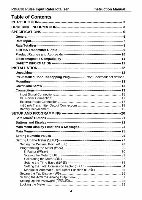
Table of Contents INTRODUCTION ---------------------------------------------------------------------- 3 ORDERING INFORMATION ------------------------------------------------------- 3 SPECIFICATIONS -------------------------------------------------------------------- 6
General ------------------------------------------------------------------------------------------- 6 Rate Input ---------------------------------------------------------------------------------------- 7 Rate/Totalizer ----------------------------------------------------------------------------------- 8 4-20 mA Transmitter Output -------------------------------------------------------------- 9 Product Ratings and Approvals ------------------------------------------------------- 10 Electromagnetic Compatibility --------------------------------------------------------- 11 SAFETY INFORMATION ------------------------------------------------------------------ 11
INSTALLATION ---------------------------------------------------------------------- 12 Unpacking ------------------------------------------------------------------------------------- 12 Pre-Installed Conduit/Stopping Plug -------------- Error! Bookmark not defined. Mounting --------------------------------------------------------------------------------------- 13 Cover Jam Screw --------------------------------------------------------------------------- 13 Connections ---------------------------------------------------------------------------------- 13
Input Signal Connections ........................................................................... 15 DC Power Connection ............................................................................... 17 External Reset Connection ........................................................................ 17 4-20 mA Transmitter Output Connections ................................................. 18 Battery Replacement ................................................................................. 19
SETUP AND PROGRAMMING -------------------------------------------------- 20 SafeTouch® Buttons ----------------------------------------------------------------------- 21 Buttons and Display ----------------------------------------------------------------------- 22 Main Menu Display Functions & Messages ---------------------------------------- 23 Main Menu ------------------------------------------------------------------------------------- 25 Setting Numeric Values ------------------------------------------------------------------- 26 Setting Up the Meter (SETUP) ------------------------------------------------------------ 27
Setting the Decimal Point (dec.PT) ............................................................. 28 Programming the Meter (PRoG) .................................................................. 29
K-Factor (Factr)---------------------------------------------------------------------- 30 Scaling the Meter (SCale) ---------------------------------------------------------- 31 Calibrating the Meter (Cal) -------------------------------------------------------- 32 Setting the Time Base (tbase) --------------------------------------------------- 34 Setting the Total Conversion Factor (totCF) --------------------------------- 34 Manual or Automatic Total Reset Function (t rST) ------------------------- 35
Setting the Tag Display (tag) .................................................................... 36 Scaling the 4-20 mA Analog Output (Aout) ............................................... 37 Setting Up the Password (PASSWRD) .......................................................... 38 Locking the Meter ...................................................................................... 38

PD6830 Pulse Input Rate/Totalizer Instruction Manual
5
Making Changes to a Password Protected Meter ..................................... 38 Disabling Password Protection .................................................................. 39
Advanced Features Menu ---------------------------------------------------------------- 40 Advanced Features Menu & Display Messages ........................................ 41 Indication (INDICAT) .................................................................................. 42 Gate Function (Gate) ................................................................................. 43 Multi-Point Linearization (LINEAR) ............................................................. 44 Contact Debounce Filter (FiLter) ............................................................. 46 Low-Flow Cutoff (CUTOFF) ......................................................................... 46 Output Internal Calibration (OCAL) ............................................................. 46 Backlight (BAKLITE) ................................................................................... 46 Information (INFO) ..................................................................................... 46
Servicing the Meter (SERVICE) ---------------------------------------------------------- 47 OPERATION -------------------------------------------------------------------------- 48
Front Panel Buttons Operation -------------------------------------------------------- 48 Resetting the Total ------------------------------------------------------------------------- 48 Maximum & Minimum Readings (MAXIMUM & MINIMUM) ------------------------ 49 Reset Meter to Factory Defaults ------------------------------------------------------- 49 Factory Defaults & User Settings ----------------------------------------------------- 50
TROUBLESHOOTING ------------------------------------------------------------- 51 Troubleshooting Tips ---------------------------------------------------------------------- 51
MOUNTING DIMENSIONS -------------------------------------------------------- 52 QUICK USER INTERFACE REFERENCE ------------------------------------ 54 EC DECLARATION OF CONFORMITY --------------------------------------- 56 Table of Figures Figure 1. PD6830 Connector Board ........................................................ 14 Figure 2. Flowmeter Powered by External Supply ................................ 15 Figure 3. Opto-Isolated Flowmeter Powered by External Supply ........ 15 Figure 4. Self-Powered Magnetic Pickup Coil Flowmeter ..................... 15 Figure 5. NPN Open Collector Input ....................................................... 16 Figure 6. PNP Sensor with External Power ............................................ 16 Figure 7. Switch Contact Input ................................................................ 16 Figure 8. DC Power Connections ............................................................ 17 Figure 9. PD6830 Reset Connections ..................................................... 17 Figure 10. 4-20 mA Output Connections ................................................ 18 Figure 11. Battery Orientation ................................................................. 19 Figure 12. Scale Menu .............................................................................. 31 Figure 13. Multi-Point Linearization Menu ............................................. 45 Figure 13. Enclosure Dimensions – Front View..................................... 52 Figure 14. Enclosure Dimensions – Side Cross Section View ............. 53
PD6830 Pulse Input Rate/Totalizer Instruction Manual
6
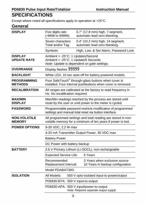
SPECIFICATIONS Except where noted all specifications apply to operation at +25°C.
General DISPLAY Five digits rate
(-9999 to 99999) 0.7" (17.8 mm) high, 7-segment, automatic lead zero blanking.
Seven characters Total and/or Tag
0.4" (10.2 mm) high, 14 segment, automatic lead zero blanking.
Symbols High, Low, & Set Alarm, Password Lock
DISPLAY UPDATE RATE
Ambient > -25°C: 1 Updates/Second Ambient < -25°C: 1 Update/5 Seconds Note: Update is dependent on gate settings.
OVERRANGE Display flashes 99999
BACKLIGHT White LED, 10 sec auto-off for battery powered models.
PROGRAMMING METHODS
Four SafeTouch® through-glass buttons when cover is installed. Four internal pushbuttons when cover is removed.
RECALIBRATION All ranges are calibrated at the factory to read frequency in Hz. No recalibration required.
MAX/MIN DISPLAY
Max/Min readings reached by the process are stored until reset by the user or until power to the meter is cycled.
PASSWORD Programmable password restricts modification of programmed settings and manual total reset via button interface.
NON-VOLATILE MEMORY
All programmed settings and total reading are stored in non-volatile memory for a minimum of ten years if power is lost.
POWER OPTIONS 9-30 VDC, 2.2 W max
4-20 mA Transmitter Output Power, 30 VDC max
Battery Power
DC Power with battery backup
BATTERY 3.6 V Primary Lithium (Li-SOCl2), non-rechargeable
Expected Service Life: 5 Years
Recommended Replacement Interval:
3 Years when exclusive source 10 Years in backup configuration
Model PDABAT36D
ISOLATION All Models: 500 V opto-isolated input-to-power/output
PD6830-BTA: 500 V input-to-output
PD6830-APA: 500 V input/power-to-output Note: Requires separate output supply

PD6830 Pulse Input Rate/Totalizer Instruction Manual
7
ENVIRONMENTAL Operating temperature range: -40 to 75°C (-20° to 75°C on battery powered models) Storage temperature range: -40 to 75°C Relative humidity: 0 to 90% non-condensing
CONNECTIONS Screw terminals accept 12 to 22 AWG wire
ENCLOSURE
Explosion-proof die cast aluminum with glass window, corrosion resistant epoxy coating, color: blue. NEMA 4X, 7, & 9, IP68. Three ¾" NPT threaded conduit openings. One ¾" NPT metal conduit/stopping plug with 12 mm hex key fitting installed.
MOUNTING May be mounted directly to conduit. Two slotted flanges for wall mounting or NPS 1½" to 2½" or DN 40 to 65 mm pipe mounting. See Mounting Dimensions on page 52.
OVERALL DIMENSIONS
5.65" x 5.25" x 4.86" (W x H x D) (144 mm x 133 mm x 124 mm)
WEIGHT 5.00 lbs (80 oz, 2.27 kg)
WARRANTY 3 years parts and labor
Rate Input
PULSE/ TRANSISTOR/ CONTACT CLOSURE INPUT
Field selectable; Sourcing or sinking pulse or square wave 0-5 V, 0-12 V, or 0-24 V; TTL; NPN or PNP transistor; Open collector 100 kΩ pull-up to 3 V; Switch contact 100 kΩ pull-up to 3 V; PNP transistor 100 kΩ pull-down to ground (COM)
Maximum Frequency: 30 kHz Minimum Pulse Width: 16 µs
OPTO-ISOLATED INPUT
Sourcing pulse or square wave 0-5 V, 0-12 V, or 0-24 V; Logic High: 4-30 V, Logic Low: < 1 V
Maximum Frequency: 10 kHz Minimum Pulse Width: 50 µs Input Current: 1 mA @ 5 V, 2.5 mA @ 12 V, 5 mA @ 24 V
LOW VOLTAGE MAG PICKUP INPUT
Sensitivity: 40 mVp-p to 24 Vp-p Maximum Frequency: 30 kHz
MINIMUM INPUT FREQUENCY
0.001 Hz Minimum frequency is dependent on high gate setting.
INPUT IMPEDANCE
Pulse input: Greater than 300 k @ 1 kHz. Open collector/switch input: 100 k pull-up to 3 V.
ACCURACY ±0.03% of calibrated span ±1 count
TEMPERATURE DRIFT
Rate display is not affected by changes in temperature.
PD6830 Pulse Input Rate/Totalizer Instruction Manual
8
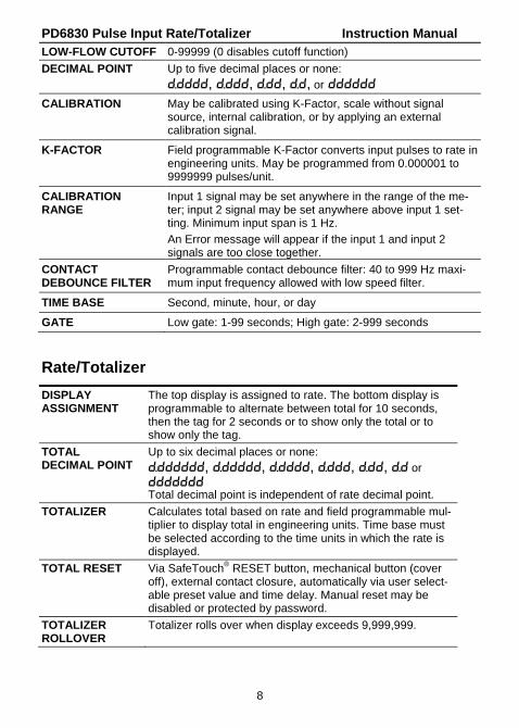
LOW-FLOW CUTOFF 0-99999 (0 disables cutoff function)
DECIMAL POINT Up to five decimal places or none: d.dddd, d.ddd, d.dd, d.d, or dddddd
CALIBRATION May be calibrated using K-Factor, scale without signal source, internal calibration, or by applying an external calibration signal.
K-FACTOR Field programmable K-Factor converts input pulses to rate in engineering units. May be programmed from 0.000001 to 9999999 pulses/unit.
CALIBRATION RANGE
Input 1 signal may be set anywhere in the range of the me-ter; input 2 signal may be set anywhere above input 1 set-ting. Minimum input span is 1 Hz.
An Error message will appear if the input 1 and input 2 signals are too close together.
CONTACT DEBOUNCE FILTER
Programmable contact debounce filter: 40 to 999 Hz maxi-mum input frequency allowed with low speed filter.
TIME BASE Second, minute, hour, or day
GATE Low gate: 1-99 seconds; High gate: 2-999 seconds
Rate/Totalizer
DISPLAY ASSIGNMENT
The top display is assigned to rate. The bottom display is programmable to alternate between total for 10 seconds, then the tag for 2 seconds or to show only the total or to show only the tag.
TOTAL DECIMAL POINT
Up to six decimal places or none: d.dddddd, d.ddddd, d.dddd, d.ddd, d.dd, d.d or ddddddd Total decimal point is independent of rate decimal point.
TOTALIZER Calculates total based on rate and field programmable mul-tiplier to display total in engineering units. Time base must be selected according to the time units in which the rate is displayed.
TOTAL RESET Via SafeTouch® RESET button, mechanical button (cover off), external contact closure, automatically via user select-able preset value and time delay. Manual reset may be disabled or protected by password.
TOTALIZER ROLLOVER
Totalizer rolls over when display exceeds 9,999,999.
PD6830 Pulse Input Rate/Totalizer Instruction Manual
9
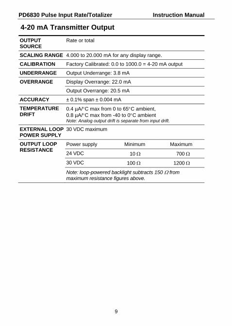
4-20 mA Transmitter Output
OUTPUT SOURCE
Rate or total
SCALING RANGE 4.000 to 20.000 mA for any display range.
CALIBRATION Factory Calibrated: 0.0 to 1000.0 = 4-20 mA output
UNDERRANGE Output Underrange: 3.8 mA
OVERRANGE Display Overrange: 22.0 mA
Output Overrange: 20.5 mA
ACCURACY ± 0.1% span ± 0.004 mA
TEMPERATURE DRIFT
0.4 µA/C max from 0 to 65C ambient, 0.8 µA/C max from -40 to 0C ambient Note: Analog output drift is separate from input drift.
EXTERNAL LOOP POWER SUPPLY
30 VDC maximum
OUTPUT LOOP RESISTANCE
Power supply Minimum Maximum
24 VDC 10 700
30 VDC 100 1200
Note: loop-powered backlight subtracts 150 from maximum resistance figures above.

PD6830 Pulse Input Rate/Totalizer Instruction Manual
10
Product Ratings and Approvals
FM Class I, Division 1, Groups B, C, D Class II, Division 1, Groups E, F, G Class III, Division 1; T6 Class I, Zone 1, AEx d IIC T6 Gb Zone 21, AEx tb IIIC T85°C Ta = -40°C to +75°C Enclosure: Type 4X & IP66 Certificate number: 3040391
ATEX II 2 G D Ex d IIC T6 Gb Ex tb IIIC T85°C Db IP68 Ta = -40°C to +75°C ATEX Certificate: Sira 10ATEX1116X
CSA Class I, Division 1, Groups B, C, D Class II, Division 1, Groups E, F, G Class III, Division 1; T6 Class I, Zone 1, Ex d IIC T6 Ta = -40°C to +75°C Enclosure: Type 4X & IP66 Certificate number: 11 2325749
IECEx IECEx SIR 10.0056X Ex d IIC T6 Gb Ex tb IIIC T85°C Db IP68 Ta = -40°C to +75°C
Special Conditions for Safe Use: Use suitably certified and dimensioned cable entry device and/or plug. The equipment shall be installed such that the supply cable is protected from mechanical damage. The cable shall not be subjected to tension or torque. If the cable is to be terminated within an explosive atmosphere, then appropriate protection of the free end of the cable shall be provided.
Year of Construction This information is contained within the serial number with the first four digits representing the year and month in the YYMM format.
For European Community: The PD6830 must be installed in accordance with the ATEX directive 94/9/EC, and the product certificate Sira 10ATEX1116X.

PD6830 Pulse Input Rate/Totalizer Instruction Manual
11
Electromagnetic Compatibility EMISSIONS EN 61326:2006
Safety requirements for measurement, control, and laboratory use – Industrial Group 1 Class A ISM emissions requirements
Radiated Emissions
Class A
IMMUNITY EN 61326:2006 Safety requirements for measurement, control, and laboratory use
ESD ±4 kV contact, ±8 kV air
RFI – Amplitude Modulated
80-1000 MHz @ 10 V/m, 1.4-2.0 GHz @ 3 V/m, 2.0-2.7 GHz @ 1 V/m, 80% AM (1 kHz)
EFT ±2 kV DC mains, ±1 kV other
Telco Surge ±1 kV
CRFI 3 V, 0.15-80 MHz, 1 kHz 80% AM
SAFETY INFORMATION
WARNINGS
Read complete instructions prior to installation and operation of the meter.
Installation and service should be performed only by trained service personnel. Service requiring replacement of internal components must be performed at the factory.
Disconnect from supply before opening enclosure. Keep cover tight while circuits are alive. Conduit seals must be installed within 18" (450mm) of the enclosure.
Verify that the operating atmosphere of the meter is consistent with the appropriate hazardous locations certifications.
If the meter is installed in a high voltage environment and a fault or installation error occurs, high voltage may be present on any lead

PD6830 Pulse Input Rate/Totalizer Instruction Manual
12
INSTALLATION For Installation in USA: The PD6830 must be installed in accordance with the National Electrical Code (NEC) NFPA 70.
For Installation in Canada: The PD6830 must be installed in accordance with the Canadian Electrical Code CSA 22.1.
For European Community: The PD6830 must be installed in accordance with the ATEX directive 94/9/EC and the product certificate Sira 10ATEX116X.
WARNING
Disconnect from supply before opening enclosure. Keep cover tight while circuits are alive. Conduit seals must be installed within 18" (450mm) of the enclosure.
Wiring connectors are accessed by opening the enclosure. Cover jam screw may need to be loosened on the cover. To access electrical connectors, remove the 2 captive screws, then disconnect the ribbon cable from the display module and set the display module aside.
Unpacking Remove the meter from box. Inspect the packaging and contents for damage. Report damages, if any, to the carrier. If any part is missing or the meter malfunctions, please contact your supplier or the factory for assistance.
Pre-Installed Conduit/Stopping Plug The PD6830 is supplied with one pre-installed conduit/stopping plug for installations that do not require the use of all three conduit entries. The conduit/stopping plug includes an internal hexagonal socket recess for removal. The pre-installed plug and its installation are included in the hazardous area approvals for the PD6830. The conduit/stopping plug has an internal 12 mm hexagonal socket recess for removal. For additional conduit/stopping plugs, see ORDERING INFORMATION on page 3.
WARNING
In hazardous areas, conduit and conduit/stopping plugs require the application of non-setting (solvent free) thread sealant. It is critical that all relevant hazardous area guidelines be followed for the installation or replacement of conduit or plugs.

PD6830 Pulse Input Rate/Totalizer Instruction Manual
13
Mounting
The PD6830 has two slotted mounting flanges that may be used for pipe mounting or wall mounting. Alternatively, the unit may be supported by the conduit using the conduit holes provided.
Refer to Mounting Dimensions, page 52 for details.
WARNING
Do not attempt to loosen or remove flange bolts while the meter is in service.
Cover Jam Screw
The cover jam screw should be properly installed once the meter has been wired and tested in a safe environment. The cover jam screw is intended to prevent the removal of the meter cover in a flameproof environment without the use of tools. Using a M2 hex wrench, turn the screw clockwise until the screw contacts the meter. Turn the screw an additional 1/4 to 1/2 turn to secure the cover. Caution: Excess torque may damage the threads and/or wrench.
Connections
WARNINGS
Static electricity can damage sensitive components.
Observe safe handling precautions for static-sensitive components.
Use proper grounding procedures/codes.
If the meter is installed in a high voltage environment and a fault or installation error occurs, high voltage may be present on any lead or terminal.
To access the connectors, loosen the cover jam screw (if tightened) with an M2 hex wrench, remove the enclosure cover and unscrew the two captive screws that fasten the display module into the enclosure. Disconnect the ribbon cable and remove the display module. Power and signal connections are made to a barrier terminal connector in the base of the enclosure. Grounding connections are made to the two ground screws provided on the base – one internal and one external. Use proper grounding techniques for explosion-proof areas and observe all local and national electric codes.

PD6830 Pulse Input Rate/Totalizer Instruction Manual
14
Connections (continued) ISO+ Isolated signal input positive terminal connection.
ISO- Isolated signal return/negative terminal connection.
S+ Signal input positive terminal connection.
S- Magnetic pickup (coil) signal return/negative terminal connection.
COM Signal return/negative, DC power return/negative, Contact closure reset return/negative terminal connection.
RST+ Contact closure reset pull-up to 3 VDC.
P+ DC Power positive terminal connection.
LP+ 4-20 mA transmitter DC power positive terminal connection.
LP- 4-20 mA transmitter regulated current output terminal connection.
Refer to Figure 1 for terminal positions.
WARNING
Observe all safety regulations. Electrical wiring should be performed in accordance with all agency requirements and applicable national, state, and local codes to prevent damage to the meter and ensure personnel safety.
ISO+ ISO- S+ S- COM RST+ P+ LP+ LP-
Figure 1. PD6830 Connector Board
PD6830 Pulse Input Rate/Totalizer Instruction Manual
15
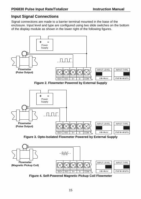
Input Signal Connections Signal connections are made to a barrier terminal mounted in the base of the enclosure. Input level and type are configured using two slide switches on the bottom of the display module as shown in the lower right of the following figures.
ISO+ ISO- S+ S- COM
Flowmeter (Pulse Output)
PowerSupply
V mV
INPUT LEVEL
PNP NPN
INPUT TYPE
Figure 2. Flowmeter Powered by External Supply
ISO+ ISO- S+ S- COM
Flowmeter (Pulse Output)
PowerSupply
V mV
INPUT LEVEL
PNP NPN
INPUT TYPE
Figure 3. Opto-Isolated Flowmeter Powered by External Supply
V mV
INPUT LEVEL
ISO+ ISO- S+ S- COM
Flowmeter (Magnetic Pickup Coil)
PNP NPN
INPUT TYPE
Figure 4. Self-Powered Magnetic Pickup Coil Flowmeter

PD6830 Pulse Input Rate/Totalizer Instruction Manual
16
ISO+ ISO- S+ S- COM
+3.0 V
100 kOhmInternal Pullup
NPNSENSOR
V mV
INPUT LEVEL
PNP NPN
INPUT TYPE
Figure 5. NPN Open Collector Input
ISO+ ISO- S+ S- COM
100 kOhmInternal Pull-Down
PNPSENSOR
PowerSupply
V mV
INPUT LEVEL
PNP NPN
INPUT TYPE
Figure 6. PNP Sensor with External Power
ISO+ ISO- S+ S- COM
+3.0 V
100 kOhmInternal Pullup
SWITCHCONTACT
V mV
INPUT LEVEL
PNP NPN
INPUT TYPE
Figure 7. Switch Contact Input
PD6830 Pulse Input Rate/Totalizer Instruction Manual
17
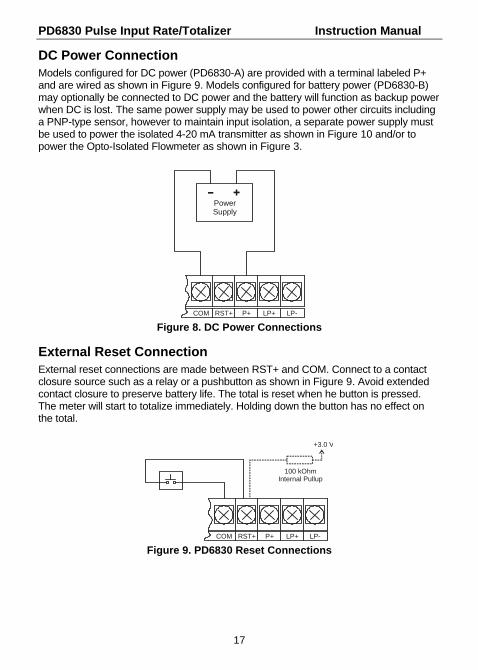
DC Power Connection Models configured for DC power (PD6830-A) are provided with a terminal labeled P+ and are wired as shown in Figure 9. Models configured for battery power (PD6830-B) may optionally be connected to DC power and the battery will function as backup power when DC is lost. The same power supply may be used to power other circuits including a PNP-type sensor, however to maintain input isolation, a separate power supply must be used to power the isolated 4-20 mA transmitter as shown in Figure 10 and/or to power the Opto-Isolated Flowmeter as shown in Figure 3.
COM RST+ P+ LP+ LP-
PowerSupply
Figure 8. DC Power Connections
External Reset Connection External reset connections are made between RST+ and COM. Connect to a contact closure source such as a relay or a pushbutton as shown in Figure 9. Avoid extended contact closure to preserve battery life. The total is reset when he button is pressed. The meter will start to totalize immediately. Holding down the button has no effect on the total.
COM RST+ P+ LP+ LP-
+3.0 V
100 kOhmInternal Pullup
Figure 9. PD6830 Reset Connections
PD6830 Pulse Input Rate/Totalizer Instruction Manual
18
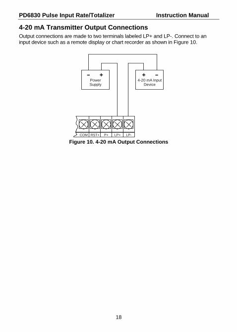
4-20 mA Transmitter Output Connections Output connections are made to two terminals labeled LP+ and LP-. Connect to an input device such as a remote display or chart recorder as shown in Figure 10.
COM RST+ P+ LP+ LP-
PowerSupply
4-20 mA InputDevice
Figure 10. 4-20 mA Output Connections

PD6830 Pulse Input Rate/Totalizer Instruction Manual
19
Battery Replacement Battery-equipped models have a battery charge monitor. When the battery is nearing the end of its capacity the screen will periodically flash the message LO BATTERY. The recommended replacement interval for models using the battery as a primary power source (without DC power at P+ terminal) is three years or within 30 days of the first low battery indication on the screen. Replacement interval on models that use battery as backup during short and infrequent DC power loss is ten years. The total is backed up in non-volatile memory when the low battery monitor trips. It is recommended that an updated reading be manually backed up prior to changing out the battery. Refer to information on preparing the meter for battery change in Servicing the Meter (SERVICE) on page 47 before changing battery.
WARNING
Fire, explosion and burns may result if not handled properly. Do not recharge, short circuit, crush, disassemble, heat above 100°C (212°F), incinerate, or expose contents to water.
Battery disposal should be in accordance with applicable regulations, which vary by location. In many locations trashing of used batteries is forbidden and disposal is done through local battery disposal facilities. Spent batteries should be packaged in such a way as to prevent short circuits during handling and transport.
NOTICE: Battery may only be replaced with an original Model PDABAT36D supplied by Precision Digital. Do not recharge battery. Do not replace with used battery. Remove cover and display module and disconnect display module ribbon cable. Carefully clip and remove the cable ties that were supplied for shipping (if present). Remove the spent battery and prepare it for disposal. Install new PDABAT36D into battery clip with polarity as shown in Figure 11. Reconnect and fasten display module. Install enclosure cover. Resume operation.
PDABAT36D
+
-
+
+++ + + + + + +
Figure 11. Battery Orientation

PD6830 Pulse Input Rate/Totalizer Instruction Manual
20
SETUP AND PROGRAMMING
There is no need to recalibrate the meter for frequency in Hz when first received from the factory.
The meter is factory calibrated for Hz prior to shipment. The calibration equipment is certified to NIST standards.
Overview Setup and programming is done through the infrared through-glass SafeTouch® buttons, or using the mechanical buttons when uncovered. There are three slide switches located on the display module. Two are used to configure the input and the other is to lock or unlock the SafeTouch® Buttons.

PD6830 Pulse Input Rate/Totalizer Instruction Manual
21
SafeTouch® Buttons
The PD6830 is equipped with four sensors that operate as through-glass buttons so that it can be programmed and operated without removing the cover (and exposing the electronics) in a hazardous area. These buttons can be disabled for security by selecting the LOCK setting on the switch located on the connector board in the base of the enclosure. To actuate a button, press and remove one finger to the glass directly over the marked button area. When the cover is removed, the four mechanical buttons located next to the sensors are used. The sensors are disabled when a mechanical button is pressed and will automatically be re-enabled after 60 seconds of inactivity.
The SafeTouch® Buttons are designed to filter normal levels of ambient interference and to protect against false triggering, however, it is recommended that the SafeTouch® Buttons be disabled (slide switch to LOCK) if there is an infrared interference source in line-of-sight to the display or if the buttons are not needed.
SafeTouch® Button Tips:
To remove cover with power applied (safe area only), or to clean the window, select CLEAN from the SERVICE menu before opening the cover or cleaning the glass. This will temporarily disable the SafeTouch® buttons for 60 seconds to prevent inadvertent use. Use the mechanical buttons while the meter is open.
To the extent possible, install the display facing away from sunlight, windows, reflective objects and any sources of infrared interference.
Keep the glass window clean.
Tighten the cover securely.
Use a password to prevent tampering.
After all connections have been completed and verified, connect the ribbon cable to the display module, fasten the display module to the base, install enclosure cover, and then apply power.

PD6830 Pulse Input Rate/Totalizer Instruction Manual
22
Buttons and Display
ACK
MAXRESET
MENU
Button Symbol
Description Symbol Status
MENU
Menu HI High Alarm Set
RESET
Right arrow/Reset LO Low Alarm Set
MAX
Up arrow/Max SET Total Alarm Set
ACK
Enter/Ack Password Enabled
Press the Menu button to enter or exit the Programming Mode at any time.
Press the Right arrow button to move to the next digit or decimal position during programming.
Press the Up arrow button to scroll through the menus, decimal point, or to increment the value of a digit.
Press the Enter/Ack button to access a menu or to accept a setting.
Press and hold the Menu button for five seconds to access the Advanced fea-tures of the meter.
PD6830 Pulse Input Rate/Totalizer Instruction Manual
23
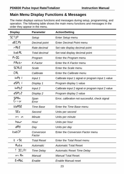
Main Menu Display Functions & Messages
The meter displays various functions and messages during setup, programming, and operation. The following table shows the main menu functions and messages in the order they appear in the menu.
Display Parameter Action/Setting
SETUP Setup Enter Setup menu
DeC..pt Decimal point Enter Decimal Point menu
Rate Rate decimal Set rate display decimal point
total Total decimal Set total display decimal point
PROG Program Enter the Program menu
Factr K-Factor Enter the K-Factor menu
sCalE Scale Enter the Scale menu
Cal Calibrate Enter the Calibrate menu
Inpt1 Input 1 Calibrate input 1 signal or program input 1 value
DspL1 Display 1 Program display 1 value
Inpt2 Input 2 Calibrate input 2 signal or program input 2 value
DsPl2 Display 2 Program display 2 value
Span Error
Span Error
Error, calibration not successful, check signal
TbASE Time Base Enter the Time Base menu
sec Second Units per second
min Minute Units per minute
hour Hour Units per hour
day Day Units per day
TotCF Conversion Factor
Enter the Conversion Factor menu
T rST Total Reset Enter the Total Reset menu
Auto Automatic Automatic Total Reset
T DELAY Time Delay Automatic Reset Time Delay
man Manual Manual Total Reset
Enabl Enable Enable Manual reset

PD6830 Pulse Input Rate/Totalizer Instruction Manual
24
Display Parameter Action/Setting
dsabl Disable Disable Manual reset
tag Tag/Units Enter the Tag/Units Menu
ON Tag On Enable Tag/Units
OFF Tag Off Disable Tag/Units
togle Tag Toggle Toggle Tag and Total
A out Transmitter Output
Enter Transmitter Output menu
Rate Rate output Set rate as output variable
total Total output Set total as output variable
Dspl1 Display 1 Output display 1 value
Out 1 Output 1 Output 1 value
Dspl2 Display 2 Output display 2 value
Out 2 Output 2 Output 2 value
PASSWRD Password Enter the Password menu
UNLOCKD Unlocked Program password to lock meter
LOCKED Locked Enter password to unlock meter
99999 Flashing display
Overrange condition
SERVICE Service Enter the Service menu
batt Change Battery Backup data and change battery
sleep Sleep Mode Low power sleep mode
CLean Clean Mode Select before removing/installing cover for ser-vice or to clean the glass window

PD6830 Pulse Input Rate/Totalizer Instruction Manual
25
Main Menu
The main menu consists of the most commonly used functions: Setup, Program, Password, and Service.
Press MENU button to enter Programming Mode then press the Up Arrow button to scroll through the main menu.
Press MENU, at any time, to exit and return to Run Mode. Changes made to settings prior to pressing Enter/ACK are not saved.
Changes to the settings are saved to memory only after pressing Enter/ACK.
The display moves to the next menu every time a setting is accepted by pressing Enter/ACK.

PD6830 Pulse Input Rate/Totalizer Instruction Manual
26
Setting Numeric Values
The numeric values are set using the Right and Up arrow buttons. Press Right arrow to select next digit and Up arrow to increment digit.
The digit being changed blinks.
Press the Enter/ACK button, at any time, to accept a setting or MENU button to exit without saving changes.
The decimal point is set using the Right or Up arrow button in the Setup-decimal point menu.
04.000
Select Next Digit
04.000 05.000
Increment Digit Accept Setting

PD6830 Pulse Input Rate/Totalizer Instruction Manual
27
Setting Up the Meter (SETUP)
The Setup menu is used to select:
1. Rate and total decimal point position
2. Program menu
3. Rate and total tag display
4. 4-20 mA transmitter output scaling
Press the Enter/Ack button to access any menu or press Up arrow button to scroll through choices. Press the Menu button to exit at any time.
A out displays onlyfor meters withanalog output option

PD6830 Pulse Input Rate/Totalizer Instruction Manual
28
Setting the Decimal Point (dec.PT) Rate decimal point may be set with up to four decimal places or with no decimal point at all. Total decimal point may be set with up to six decimal places or with no decimal point at all. Rate decimal and total decimal are programmed individually.
Pressing the Right arrow moves the decimal point one place to the right until no decimal point is displayed. Pressing the Up arrow moves the decimal point one place to the left.
dec.ptSeTUP
RATEDECIMAL
dd.dddRATE
TOTALDECIMAL
Select TotalDecimal Point
ToTALddddd.dd
Select RateDecimal Point
or
or
PD6830 Pulse Input Rate/Totalizer Instruction Manual
29
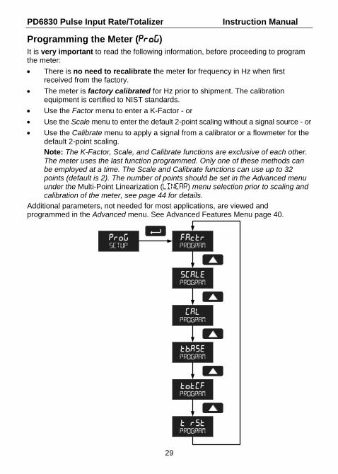
Programming the Meter (PRoG) It is very important to read the following information, before proceeding to program the meter:
There is no need to recalibrate the meter for frequency in Hz when first received from the factory.
The meter is factory calibrated for Hz prior to shipment. The calibration equipment is certified to NIST standards.
Use the Factor menu to enter a K-Factor - or
Use the Scale menu to enter the default 2-point scaling without a signal source - or
Use the Calibrate menu to apply a signal from a calibrator or a flowmeter for the default 2-point scaling.
Note: The K-Factor, Scale, and Calibrate functions are exclusive of each other. The meter uses the last function programmed. Only one of these methods can be employed at a time. The Scale and Calibrate functions can use up to 32 points (default is 2). The number of points should be set in the Advanced menu under the Multi-Point Linearization (LINEAR) menu selection prior to scaling and calibration of the meter, see page 44 for details.
Additional parameters, not needed for most applications, are viewed and programmed in the Advanced menu. See Advanced Features Menu page 40.
PD6830 Pulse Input Rate/Totalizer Instruction Manual
30
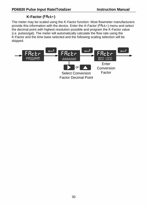
K-Factor (Factr) The meter may be scaled using the K-Factor function. Most flowmeter manufacturers provide this information with the device. Enter the K-Factor (Factr) menu and select the decimal point with highest resolution possible and program the K-Factor value (i.e. pulses/gal). The meter will automatically calculate the flow rate using the K-Factor and the time base selected and the following scaling selection will be skipped.
FactrPROGRAM
Factr0001.000
Factrdddd.ddd
Select ConversionFactor Decimal Point
orEnter
ConversionFactor

PD6830 Pulse Input Rate/Totalizer Instruction Manual
31
Scaling the Meter (SCale) The pulse input can be scaled to display the process variable in engineering units. A signal source is not needed to scale the meter; simply program the inputs and corresponding display values.
Figure 12. Scale Menu
For instructions on how to program numeric values see Setting Numeric Values, page 26.

PD6830 Pulse Input Rate/Totalizer Instruction Manual
32
Calibrating the Meter (Cal)
To scale the meter without a signal source refer to K-Factor (Factr) or Scaling the Meter (SCale) on page 30.
The pulse input can be calibrated to display the process in engineering units by applying the appropriate input signal and following the calibration procedure.
The use of a calibrated signal source is strongly recommended.
1. Press the Up arrow button to scroll to the Calibration menu (cAL) and press
Enter.
2. The meter displays inpt1. Apply a known signal and press Enter. The display will flash while accepting the signal.
3. After the signal is accepted, the meter displays dspl1 Press Enter. Enter a corresponding display value for the signal input, and press Enter to accept.
4. The meter displays inpt2. Apply a known signal and press Enter. The display will flash while accepting the signal.
5. After the signal is accepted, the meter displays dspl2. Press Enter. Enter a corresponding display value for the signal input and press Enter to accept.
6. After completing calibration the save? display will need to be acknowledged using the Enter key before calibration will take effect.

PD6830 Pulse Input Rate/Totalizer Instruction Manual
33
Error Message (Error) An error message indicates that the calibration or scaling process was not successful. After the error message is displayed, the meter reverts to input 2 during calibration or scaling, allowing the appropriate input signal to be applied or programmed.
The error message might be caused by any of the following conditions:
1. Input signal is not connected to the proper terminals or it is connected backwards.
2. Minimum input span requirements not maintained.
3. Input 1 signal inadvertently applied to calibrate input 2.
Minimum Input Span The minimum allowed input span is 1 Hz, which is the minimum difference between input 1 and input 2 signals required to complete the calibration or scaling of the meter.

PD6830 Pulse Input Rate/Totalizer Instruction Manual
34
Setting the Time Base (tbase) The meter calculates rate based on K-Factor and a time base of units per second, minute, hour, or day.
Press the Enter/Ack button, at any time, to accept a setting or Menu button to exit without saving changes.
tbaseSETUP
SECT BASE
nminT BASE
hourT BASE
DayT BASE
Setting the Total Conversion Factor (totCF)
Total Conversion Factor is used to convert to a different unit of total display. For example, to display rate in gallons and total in liters, enter a conversion factor of 3.7854. When rate and total units are the same, the Conversion Factor should be 1.0000.
Press the Enter/Ack button, at any time, to accept a setting or Menu button to exit without saving changes.
TOTCFSETUP
3.7854TOT CF
d.ddddTOT CF
Select ConversionFactor Decimal Point
orEnter
ConversionFactor

PD6830 Pulse Input Rate/Totalizer Instruction Manual
35
Manual or Automatic Total Reset Function (t rST) For manual reset, select PROGRAM t rst man and then next select whether manual reset will be enabled (Enabl) or disabled (dsabl) using the up arrow key and by then pressing the Enter/Ack button to accept. Disabling reset will avoid inadvertent resets of the total via the front reset button or external reset contact.
For automatic reset, select PROGRAM t rst Auto T DELAY and enter reset delay time in seconds. Once the set point is reached, the meter waits for a programmed amount of time (T DELAY) and then resets the total to zero.
The meter may be automatically reset based on the value programmed in the Advanced menu: INDICAT alrm total SEt.
Press the Enter/Ack button, at any time, to accept a setting; otherwise press the Menu button to exit without saving changes.
t rstSeTUP
nmanT RESET
AutoT RESET
Enter Reset Delay(seconds)
00010T DELAY
enablMAN RST
DSABLMAN RST

PD6830 Pulse Input Rate/Totalizer Instruction Manual
36
Setting the Tag Display (tag) The meter can be set to display a combination of seven alphanumeric characters for engineering units (e.g. GALLONS); for identification (e.g. TANK 3); or for dual rate/total units (e.g. GPS/GAL, LPM/LTR,, BPH/BBL). Press Right arrow to select next character and Up arrow to increment character.
To automatically cycle the lower display between total reading for ten seconds and tag for two seconds, choose togle.
To disable the tag display and show only total reading uninterrupted on the lower display, choose Off.
To show tag only on the lower display, choose On. Totalizing continues in the background, but is not shown while On is selected.
Selecting On or togle prompts for entry of the tag.
The unit being changed blinks.
Press the Enter/ACK button, at any time, to accept a setting or Menu button to exit without saving changes.
tagSeTUP
ONTAG
TAGABCDEFG
OFFTAG
TAGABCDEFG
TAGACCDEFG
togleTAG

PD6830 Pulse Input Rate/Totalizer Instruction Manual
37
Scaling the 4-20 mA Analog Output (Aout) The 4-20 mA analog output (if equipped) can be scaled to provide a 4-20 mA signal for any display range selected for either the rate or the total.
No equipment is needed to scale the analog output; simply program the display values to the corresponding mA output signal. The meter is factory calibrated for milliamps.
The Analog Output menu is used to program the 4-20 mA output based on display values.
For instructions on how to program numeric values see Setting Numeric
Values, page 26.
!
CAUTION
Please note that when power is removed from the meter, the analog output will remain at the last value transmitted at the time of power loss. Take this effect into consideration when designing any system using the 4-20 mA output.
PD6830 Pulse Input Rate/Totalizer Instruction Manual
38
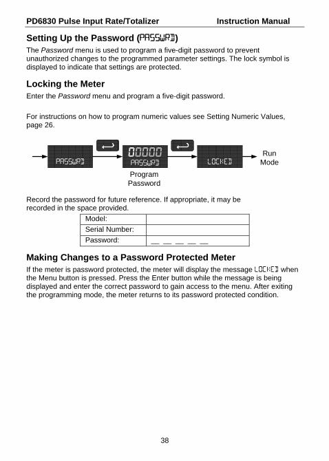
Setting Up the Password (PASSWRD) The Password menu is used to program a five-digit password to prevent unauthorized changes to the programmed parameter settings. The lock symbol is displayed to indicate that settings are protected.
Locking the Meter Enter the Password menu and program a five-digit password.
For instructions on how to program numeric values see Setting Numeric Values, page 26.
00000passWRD
ProgramPassword
passWRD LOCKED
RunMode
Record the password for future reference. If appropriate, it may be recorded in the space provided.
Model:
Serial Number:
Password: __ __ __ __ __
Making Changes to a Password Protected Meter If the meter is password protected, the meter will display the message LOCKED when the Menu button is pressed. Press the Enter button while the message is being displayed and enter the correct password to gain access to the menu. After exiting the programming mode, the meter returns to its password protected condition.

PD6830 Pulse Input Rate/Totalizer Instruction Manual
39
Disabling Password Protection To disable the password protection, access the Password menu and enter the correct password twice, as shown below. The meter is now unprotected until a new password is entered.
EnterPassword
3024.7GALLONS
Run Mode
LOCKED
00000LOCKED
SETUP
00000PASSWRDPASSWRD
UNLOCKD
Re-EnterPassword
UNLOCKD
Run Mode
If the correct six-digit password is entered, the meter displays the message UNLOCKD (unlocked) and the protection is disabled until a new password is programmed.
If the password entered is incorrect, the meter displays the message LOCKED for about two seconds, and then it returns to Run Mode. To try again, press Enter while the Locked message is displayed.
Did you forget the password? The password may be disabled by entering a master password. If you are authorized to make changes, enter the master password 50865 to unlock the meter permanently. Unlike password disabling, the master password is entered only once to unprotect the meter.

PD6830 Pulse Input Rate/Totalizer Instruction Manual
40
Advanced Features Menu
To simplify the setup process, functions not needed for most applications are located in the Advanced features menu. Press and hold the MENU button for five seconds to access the Advanced features menu.
Press the Enter/Ack button to access any menu or press Up arrow button to scroll through choices. Press the Menu button to exit at any time.

PD6830 Pulse Input Rate/Totalizer Instruction Manual
41
Advanced Features Menu & Display Messages The following table shows the Advanced features menu functions and messages in the order they appear in the menu.
Display Parameter Action/Setting
INDICAT Indication Enter Indication menu
OFF Off Alarm indication Off
Alrm Alarm Indication Enter Alarm menu
Rate Rate Alarm Assign alarm to rate
Total Total Assign alarm to total
Set Set Point Program set point
Reset Reset Point Program reset point (rate only)
GATE Gate Enter Gate menu
LO Low Gate Set Low Gate
HI High Gate Set High Gate
LINEAR Linearization Enter Linearization menu
NO pTs Number of Points Enter number of points
FILTER Filter Enter filter menu
HI High Speed Filter Set high speed filter
LO Low Speed Filter Set low speed (contact debounce) filter
CUTOFF Low-Flow Cutoff Set low-flow cutoff
OCAL Output Calibration Analog output calibration (Factory use only)
BAKLITE Backlight Enable or disable backlight
INFO Meter Information
Show software number and version, or reset to factory defaults
SFT Software Software number
ver Software Version Software version
RESET DFALTS?
Reset Defaults Restore factory default parameter settings

PD6830 Pulse Input Rate/Totalizer Instruction Manual
42
For instructions on how to program numeric values see Setting Numeric Values, page 26.
Indication (INDICAT) The Indication menu is used to enable and set up a high or low rate alarm or total set point alarm indication on the screen. When in alarm condition, a HI, LO, or SET symbol is displayed accompanied by a flashing display until the ACK is pressed or the condition is cleared (reset).
Rate high alarm trip point: program set point above reset point.
Rate low alarm trip point: program set point below reset point.
Rate alarm deadband is determined by the difference between set and reset points. Minimum deadband is one display count. If set and reset points are pro-grammed the same, output will reset one count below set point.
Total alarm trip point: program total set point. Alarm reset is triggered by total reset (There is no reset parameter entered for total). If automatic total reset is enabled, this setting will be the trigger point for the timer.
INDICAT
ALRNmINDICAT
offINDICAT
AcceptSetting
setRATE
EnterSet Point
1000.0SET
resetRATE
Enter Reset Point
0500.0RESET
rateALARM
totalALARM
setTOTAL
SET001000.0
Enter Set Point
To acknowledge alarm, press the ENTER/ACK button once for acknowledge prompt and a second time to confirm.

PD6830 Pulse Input Rate/Totalizer Instruction Manual
43
Gate Function (Gate) The gate function is used for displaying slow pulse rates. Using the programmable gate, the meter is able to display pulse rates as slow as 1 pulse every 999 seconds (0.001 Hz). The gate function can also be used to obtain a steady display reading with a fluctuating input signal.
There are two settings for the Gate, low gate (Lo Gate) and high gate (HI Gate).
Low Gate (Lo Gate) For most applications, low gate setting should be left at 1 second. Increase low gate setting to obtain a steadier rate display. The rate display will update in accordance with the low gate setting, for example if low gate is set at 10, the display will update every 10 seconds; changes in rate between updates will not be reflected until next display update.
High Gate (HI Gate) Set the high gate value to correspond to the highest expected pulse period (lowest pulse rate). For instance if the meter must display a rate when there is 1 pulse coming into the meter every 10 seconds, set the high gate to 11 seconds. When the signal is removed from the meter, the display will show the last reading for 11 seconds; then it will read zero.

PD6830 Pulse Input Rate/Totalizer Instruction Manual
44
Multi-Point Linearization (LINEAR) Up to 32 linearization points can be selected under the Linear function. The multi-point linearization can be used to linearize the display for non-linear signals such as those from level transmitters used to measure volume in odd-shaped tanks or to convert level to flow using weirs and flumes that require a complex exponent. These points are established via direct entry (SCALE) or with an external calibration signal (CAL).
Number of Points (NO PTs) Enter number of linearization points. The default value is 2 points. After entering the number of points, the next selection is Scaling (page 31) or Live Input Calibration (page 32).
Manual Entry (SCALE) Manual entry of the linearization data is done once the number of points has been selected (NO PTS). Input signal levels (InP 1-32) for up to 32 points, along with the desired/corresponding meter reading (dSP 1-32) should be entered for each lineari-zation point. See Figure 13 on page 45.
External Calibration (CAL) Linearization data can be entered using a known accurate signal source (InP 1-32) and then entering the desired/corresponding meter reading (disp 1-32) for that input signal level See Figure 13 on page 45.
Important Navigation Note: After entering the last display value, the linearization entries must be saved (SAUE?) before they will be put into effect. However, you may move past this selection using the Up arrow key if you need to go back and correct and earlier entry. Once confident in the entries however, the user must navigate back to the Save menu screen (SAUE?) and press the Enter/Ack key to save the changes.

PD6830 Pulse Input Rate/Totalizer Instruction Manual
45
LINEAR PROGRAM PROGRAM
CAL
inP 1
CAL
dsp 1
DSPLY 1
0000.0
CAL
INP 2
Figure 13. Multi-Point Linearization Menu

PD6830 Pulse Input Rate/Totalizer Instruction Manual
46
Contact Debounce Filter (FiLter) The filter function (FiLter) can be used for applications where the meter is set up to count pulses generated by switch contacts. There are two settings, HI (high speed) and LO (low speed). High speed disables the contact debounce filter and allows any pulse of the minimum specified width for the input wired. Press ENTER when LO is displayed to enable the filter function. Program the filter value for the maximum fre-quency of the true pulse signal in Hz that is expected plus a small margin. In most applications, a setting of 40 will be sufficient to debounce a contact closure, yet allow a pulse train up to 40 Hz.
Low-Flow Cutoff (CUTOFF) The low-flow cutoff feature allows the meter to be programmed so that the often-unsteady output from a transmitter at low flow rates, always displays zero on the meter.
The cutoff value may be programmed from -99999 to 99999. Below the cutoff value, the meter will display zero. Programming the cutoff value to zero disables the cutoff feature.
Output Internal Calibration (OCAL) This feature is only used at the factory and for diagnostic purposes. It is not recommended to access this menu without instruction from technical support.
Backlight (BAKLITE) The Backlight menu is used to enable or disable the backlight. This feature is particularly important for the battery-powered models with momentary backlight.
Information (INFO) The Information menu is part of the Advanced features menu. It shows software identification number and version number. To determine the software version of a meter:
Go to the Information menu (INFO) and press ENTER button.
Continue pressing ENTER to scroll through the software release number and software version.
Following the information display, the meter will exit the Advanced features menu and return to run mode.

PD6830 Pulse Input Rate/Totalizer Instruction Manual
47
Servicing the Meter (SERVICE)
The Service menu is used to access features used for maintenance. It is
Select batt to backup the current total into nonvolatile memory and prepare for a battery swap. Once this is selected, the display will flash Chang BATTERY al-lowing up to 5 minutes for battery removal before it will automatically exit the menu and return to run mode.
Select Sleep to enter low power sleep mode. In sleep mode, the display elec-tronics power down to prolong battery life. Incoming pulses are ignored in this mode. The display and output returns to normal operation with the press of a mechanical button, SafeTouch® button, or external reset contact.
!
CAUTION
The 4-20 mA transmitter output continues at the level it was last updated before sleep mode was entered.
Select CLEAN from the service menu to temporarily disable the SafeTouch® but-tons to prevent inadvertent use. Buttons will automatically resume operation af-ter 60 seconds. The display blinks the message CLEAN SERVICE. This should be used when cleaning the window and when installing or removing the cover while power is applied (in a safe area only). The clean feature is not shown in the menu when the SafeTouch® buttons are disabled using the slide switch located on the connector board.
SERVICE
BATTSERVICE
CLEANSERVICE
SLEEPSERVICE

PD6830 Pulse Input Rate/Totalizer Instruction Manual
48
OPERATION
Front Panel Buttons Operation
Button Symbol
Description
MENU
Press to enter or exit Programming Mode or exit Max/Min readings
RESET
Press to reset total (if enabled) Press to reset Max/Min readings
MAX
Press to display Max/Min readings alternately
ACK
Press to acknowledge alarm (if enabled) Press to display Max or Min reading indefinitely while displaying Max or Min
Resetting the Total
If manual total reset is enabled in the Program Menu, the total may be reset by press-ing the RESET button and then ACK button. Additionally, the total may be reset using a normally open pushbutton connected across the terminals RST+ and COM.
Note: The total is cleared immediately when ACK button is pressed. Totalization will then continue, even if the ACK button or external reset button continues to be pressed.

PD6830 Pulse Input Rate/Totalizer Instruction Manual
49
Maximum & Minimum Readings (MAXIMUM & MINIMUM)
The maximum and minimum (peak & valley) readings reached by the rate are stored in the meter since the last reset or power-up. The meter shows MAXIMUM or MINIMUM to differentiate between run mode and max/min display. Press ENTER to remain in Max/Min display mode. If ENTER is not pressed, the Max/Min display reading will time out after ten seconds. The meter will return to display the actual reading.
4065.3MAXIMUM
3024.7GALLONS
Run Mode
2457.7MINIMUM
Press Up to Display and toToggle Between Max & Min
10 Sec Time Out
Press Enter to hold Max/Min
Press Right to Reset Max/Min
Press Menu to Exit Max/Min
Reset Meter to Factory Defaults
When the parameters have been changed in a way that is difficult to determine what’s happening, it might be better to start the setup process from the factory defaults.
Instructions to load factory defaults:
Enter the Advanced features menu.
Press and hold RESET button when INFO is shown.
Press ENTER when RESET DFALTS? prompt is shown
Note: If ENTER is not pressed within three seconds, the prompt will stop flashing return to showing INFO.
INFO
RESETDFALTS? LOADING
Press andHold for 5 sec
FlashingDisplay
DefaultsRestored
PD6830 Pulse Input Rate/Totalizer Instruction Manual
50
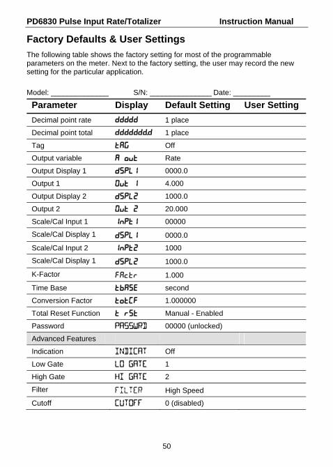
Factory Defaults & User Settings
The following table shows the factory setting for most of the programmable parameters on the meter. Next to the factory setting, the user may record the new setting for the particular application.
Model: ______________ S/N: _______________ Date: _________
Parameter Display Default Setting User Setting
Decimal point rate Ddddd 1 place
Decimal point total Ddddddd.d 1 place
Tag tag Off
Output variable A out Rate
Output Display 1 Dspl1 0000.0
Output 1 Out 1 4.000
Output Display 2 Dspl2 1000.0
Output 2 Out 2 20.000
Scale/Cal Input 1 Inpt1 00000
Scale/Cal Display 1 dspl1 0000.0
Scale/Cal Input 2 Inpt2 1000
Scale/Cal Display 1 Dspl2 1000.0
K-Factor Factr 1.000
Time Base tbase second
Conversion Factor TotCF 1.000000
Total Reset Function T rst Manual - Enabled
Password PASSWRD 00000 (unlocked)
Advanced Features
Indication INDICAT Off
Low Gate LO GATE 1
High Gate HI GATE 2
Filter FILTER High Speed
Cutoff CUTOFF 0 (disabled)

PD6830 Pulse Input Rate/Totalizer Instruction Manual
51
TROUBLESHOOTING The rugged design and the user-friendly interface of the meter should make it unusual for the installer or operator to refer to this section of the manual. If the meter is not working as expected, refer to the recommendations below.
Troubleshooting Tips
Symptom Check/Action
No display or faint display Check power connection.
Rate display unsteady Increase low gate setting in Advanced menu.
Meter displays error message during calibration (Span eRROR)
Verify minimum input span requirements
Meter flashes 99999 Check input signal is within scaled range of 99999.
Display stuck displaying MAXIMUM or MINIMUM
Press Menu to exit Max/Min display readings.
Display response is too slow Check gate settings to see if they can be lowered.
If the display locks up or the meter does not respond at all
Perform hard reset by removing and reconnecting the display module or by removing external loop or DC power.
Backlight does not appear. Backlight is intended for viewing assistance in dim lighting conditions. It may not be noticeable under good lighting conditions. Battery powered models turn off the backlight after ten seconds of button inactivity.
Other symptoms not described above Call Technical Support for assistance.
SafeTouch® Buttons do not respond Service menu was selected or mechanical button was pushed. The SafeTouch® Buttons will be re-enabled automatically after a 5 minute delay from the last button push.
If slide switch on display module is in Lock position, switch to Unlock.
Sunlight can interfere with the sensors. It is recommended to shield the window from sunlight while operating the buttons by standing so as to block direct sunlight.

PD6830 Pulse Input Rate/Totalizer Instruction Manual
52
MOUNTING DIMENSIONS All units: inches [mm]
Figure 14. Enclosure Dimensions – Front View

PD6830 Pulse Input Rate/Totalizer Instruction Manual
53
Figure 15. Enclosure Dimensions – Side Cross Section View

PD6830 Pulse Input Rate/Totalizer Instruction Manual
54
QUICK USER INTERFACE REFERENCE
Program
RunMax &
MinAdvancedFeatures
Up Arrow
Menu
Menu
Menu Menu
Operational Modes
Menu for 5seconds
Pushbutton FunctionMenu Go to Programming Mode or leave Programming, Advanced
Features, and Max/Min Modes.Right Arrow Move to next digit or decimal point position. Reset Total.Up Arrow Move to next selection or increment digit. Go to Max/Min Mode.Enter/Ack Accept selection/value and move to next selection.
Acknowledge Alarm.
Menu held for 5 seconds enters Advanced Features Menu
Max/Min ModeWhile in Run Mode, pressing Up Arrow will initiate Max/Min Mode. Up Arrow togglesbetween Max & Min displays, and Right Arrow resets the Max/Min to the currentvalue. Press Menu or wait 10 seconds to return to Run Mode. Pressing Enter/Ack willdisable the 10 second timeout and continuously display Max or Min.

PD6830 Pulse Input Rate/Totalizer Instruction Manual
55

PD6830 Pulse Input Rate/Totalizer Instruction Manual
56
EC DECLARATION OF CONFORMITY Issued in accordance with ATEX Directive 94/9/EC
Manufacturer: Precision Digital Corporation
89 October Hill Rd Ste 5
Holliston, MA 01746 USA
Device: PD6830 Series Pulse Input Rate/Totalizer
Notified Body: Sira Certification Service, notified body no. 0518
Rake Lane, Eccleston, Chester, CH4 9JN, England
EC Type Examination Certificate: Sira 10ATEX1116X
Quality Assurance Notification No.: SIRA 10 ATEX M462
Compliance with Standards: Product Markings:
EN 60079-0:2009 II 2 G D
EN 60079-1:2007 Ex d IIC T6 Gb
EN 60079-31:2008 Ex tb IIIC T85°C Db IP68
EN 61326:2006 Tamb -40°C to +75°C
IEC 61010-1:2001 & EN 61010-1:2001, including Group and National Differences as they apply for AU, CA, US and KR
Community Directives:
94/9/EC ATEX Directive
2004/108/EC EMC Directive
Name: Jeffrey Peters
Company: Precision Digital Corporation
Title: President
Date: 1/1/2011

PD6830 Pulse Input Rate/Totalizer Instruction Manual
57
NOTES

PD6830 Pulse Input Rate/Totalizer Instruction Manual
58
NOTES

PD6830 Pulse Input Rate/Totalizer Instruction Manual
59
NOTES

PD6830 Pulse Input Rate/Totalizer Instruction Manual
LIM6830_B SFT050 Ver 1.000 & up
06/11
How to Contact Precision Digital
For Technical Support:
Call: (800) 610-5239 or (508) 655-7300
Fax: (508) 655-8990
Email: [email protected]
For Sales Support:
Call: (800) 343-1001 or (508) 655-7300
Fax: (508) 655-8990
Email: [email protected]
For the latest version of this manual please visit:
www.predig.com