rohs-compliant 5-phase stepping motor and driver ... 5-phase stepping motor and driver package...
TRANSCRIPT
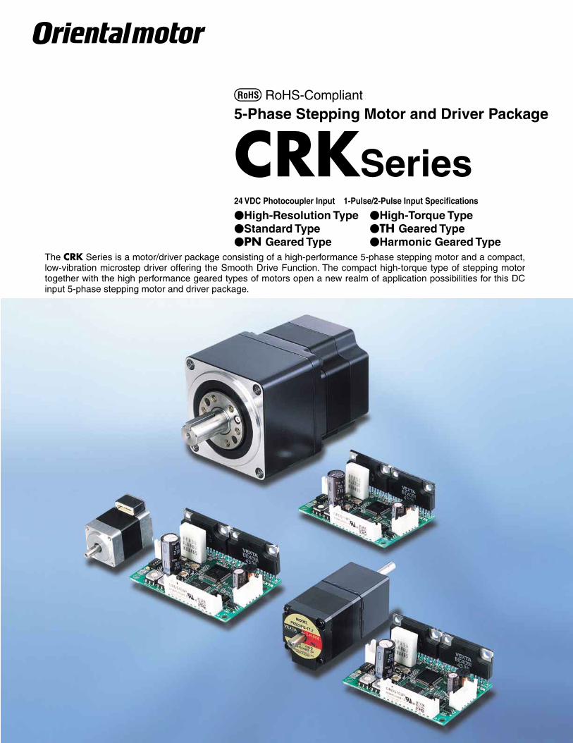
RoHS-Compliant
5-Phase Stepping Motor and Driver Package
CRKSeries24 VDC Photocoupler Input 1-Pulse/2-Pulse Input Specifications
High-Resolution Type High-Torque TypeStandard Type TH Geared TypePN Geared Type Harmonic Geared Type
The CRK Series is a motor/driver package consisting of a high-performance 5-phase stepping motor and a compact, low-vibration microstep driver offering the Smooth Drive Function. The compact high-torque type of stepping motor together with the high performance geared types of motors open a new realm of application possibilities for this DC input 5-phase stepping motor and driver package.

2
5-Phase Stepping Motor and Driver Package
CRK Series
The CRK Series is a motor/driver unit combining a high-performance, 5-phase stepping motor with a compact, low-vibration microstep driver offering the Smooth Drive Function. Four frame sizes of 20 mm (0.79 in.), 28 mm (1.10 in.), 42 mm (1.65 in.) and 60 mm (2.36 in.) are available, and there are models fi tted with various geared motors.
Features
Newly Designed Motors High-Resolution Motor · Improved Stopping Accuracy The basic step angle of the high-resolution type is 0.36˚/step, which is half the basic step angle of the standard type. The positioning accuracy of stepping motors is affected by frictional load. The CRK's high-resolution type, having a smaller basic step angle and capable of generating approx. 1.5 times the torque of the standard type, ensures quick torque rise, thereby minimizing the effect of frictional load.
Comparison of Angle-Torque Characteristics
-1.5
0.5
0
1
1.5
-1.8 -0.9 0.9 1.8
TH1
TL
TorqueTL: Friction TorqueTH1,TH2: Maximum Holding Torque
TH2
-0.5
-1
-TL
High-Resolution Type
Standard Type
Angle [deg]
TH1: CRK566AP (Standard Type)TH2: CRK566PMAP (High-Resolution Type)
· Static Angle Error of 2 Arc Minutes (No Load) The high-resolution type is designed with a static angle error of 2 arc minutes (0.034˚) [standard type: 3 arc minutes (0.05˚)]. The reduced error helps improve the positioning accuracy of your equipment.
Static Angle Characteristics
Angl
e Er
ror [
deg]
Angle [deg]
Power Supply Voltage: 24 VDC Resolution 1 (0.36˚/step)
-0.06-0.05-0.04-0.03-0.02-0.01
00.010.020.030.040.050.06
0 60 120 180 240 300 360
CRK566PMBP
High-Torque Motor The high-resolution type and high-torque type adopt a newly designed high-torque motor that widens the range of applications. The smaller motor allows for compact equipment design. The motor current is reduced to suppress heat generation. Example) Avoidance of temperature rise in precision equipment or
machinery
Comparison of Speed vs. Torque Characteristics
1.6
0
0.4
0 100 200 300 400 500 600 700 800 900 1000
0.8
1.2
Current: 1.4A/Phase Step Angle: 0.36˚/stepWith Damper D6CL-8.0F: JL=140107kg·m2 (0.77 oz-in2)
Speed [r/min]
Torq
ue [N
·m]
CRK566PMBP(High-Resolution Type)
CRK566BP(Standard Type)
0
100
150
200
50
Torq
ue [o
z-in
]
RoHS-Compliant
3
Connector Coupling Design The high-resolution type and high-torque type adopt a connector-coupled motor to ensure greater ease of handling. There is no need to cut lead wires or pressure-bond the connector. You can also select a cable of desired length and type. The connector coupling design also makes maintenance easy. The CRK package comes with a motor leadwire/connector assembly [0.6 m (2 ft.)].
Wide Range of Motor Variations The CRK Series offers models of the high-resolution type, high-torque type and standard type, as well as various geared types. You can find a product meeting your specific torque, resolution or other needs from a total of 98 different specifications.
Compact, Lightweight Microstep Driver The driver in the CRK Series achieves microstep drive in a compact, lightweight body. A new IC allows the driver to provide various functions, including the following:
Smooth Drive Function 1-pulse/2-pulse input mode switching 25 preset step angles Power LED Photocoupler input
65 mm
(2.56 in.)45 mm(1.77 in.)
25 mm(0.98 in.)
Mass: 40 g (0.088 lb.)
Lower Vibration and Noise Achieved by Microstep DriveThe basic step angle of the motor can be divided into a maximum of 250 microstep angles without using any mechanical element such as a reduction gear. As a result, vibration and noise are further reduced.
Improved 5-Phase Performance can Usually be Easily Integrated into an Existing 2-Phase System
The basic step angle can be adjusted to match a 2-phase stepping motor's step angles, so a switchover from the 2-phase microstep mode can be easily made, without having to change input pulses.
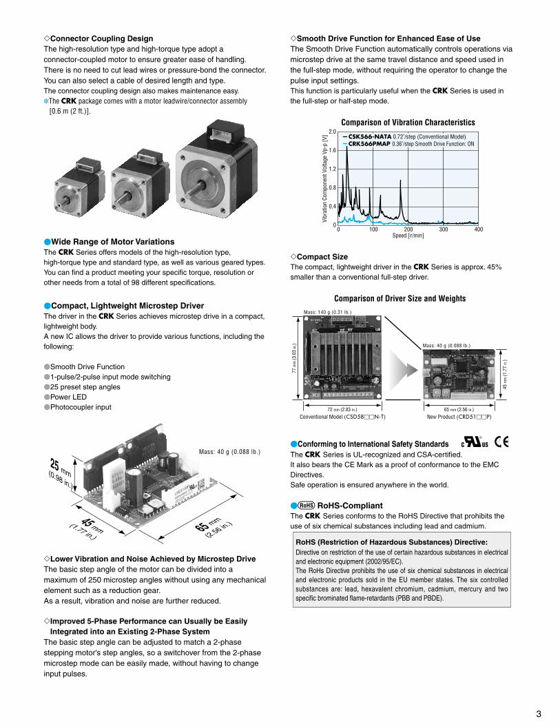
Smooth Drive Function for Enhanced Ease of UseThe Smooth Drive Function automatically controls operations via microstep drive at the same travel distance and speed used in the full-step mode, without requiring the operator to change the pulse input settings. This function is particularly useful when the CRK Series is used in the full-step or half-step mode.
Comparison of Vibration Characteristics2.0
1.6
1.2
0.8
0.4
00 100 200 300 400
Speed [r/min]
Vibr
atio
n Co
mpo
nent
Vol
tage
Vp-
p [V
] CSK566-NATA 0.72˚/step (Conventional Model)CRK566PMAP 0.36˚/step Smooth Drive Function: ON
Compact Size The compact, lightweight driver in the CRK Series is approx. 45% smaller than a conventional full-step driver.
Mass: 40 g (0.088 lb.)
Conventional Model (CSD58N-T)72 mm (2.83 in.)
New Product (CRD51P)65 mm (2.56 in.)
77 m
m (3
.03
in.)
45 m
m (1
.77
in.)
Mass: 140 g (0.31 lb.)
Comparison of Driver Size and Weights
Conforming to International Safety Standards The CRK Series is UL-recognized and CSA-certified. It also bears the CE Mark as a proof of conformance to the EMC Directives. Safe operation is ensured anywhere in the world.
RoHS-Compliant The CRK Series conforms to the RoHS Directive that prohibits the use of six chemical substances including lead and cadmium.
RoHS (Restriction of Hazardous Substances) Directive: Directive on restriction of the use of certain hazardous substances in electrical and electronic equipment (2002/95/EC).The RoHs Directive prohibits the use of six chemical substances in electrical and electronic products sold in the EU member states. The six controlled substances are: lead, hexavalent chromium, cadmium, mercury and two specific brominated flame-retardants (PBB and PBDE).
4
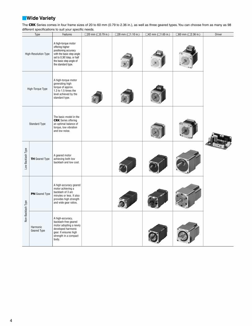
Wide VarietyThe CRK Series comes in four frame sizes of 20 to 60 mm (0.79 to 2.36 in.), as well as three geared types. You can choose from as many as 98 different specifications to suit your specific needs.
Type Features 20 mm (0.79 in.) 28 mm (1.10 in.) 42 mm (1.65 in.) 60 mm (2.36 in.) Driver
High-Resolution Type
A high-torque motor offering higher positioning accuracy with the basic step angle set to 0.36˚/step, or half the basic step angle of the standard type.
High-Torque Type
A high-torque motor generating high torque of approx. 1.3 to 1.5 times the level achieved by the standard type.
Standard Type
The basic model in the CRK Series offering an optimal balance of torque, low vibration and low noise.
Low
Bac
klas
h Ty
pe
TH Geared TypeA geared motor achieving both low backlash and low cost.
Non-
Back
lash
Typ
e
PN Geared Type
A high-accuracy geared motor achieving a backlash of 3 arc minutes or less. It also provides high strength and wide gear ratios.
Harmonic Geared Type
A high-accuracy, backlash-free geared motor adopting a newly developed harmonic gear. It ensures high strength in a compact body.
5
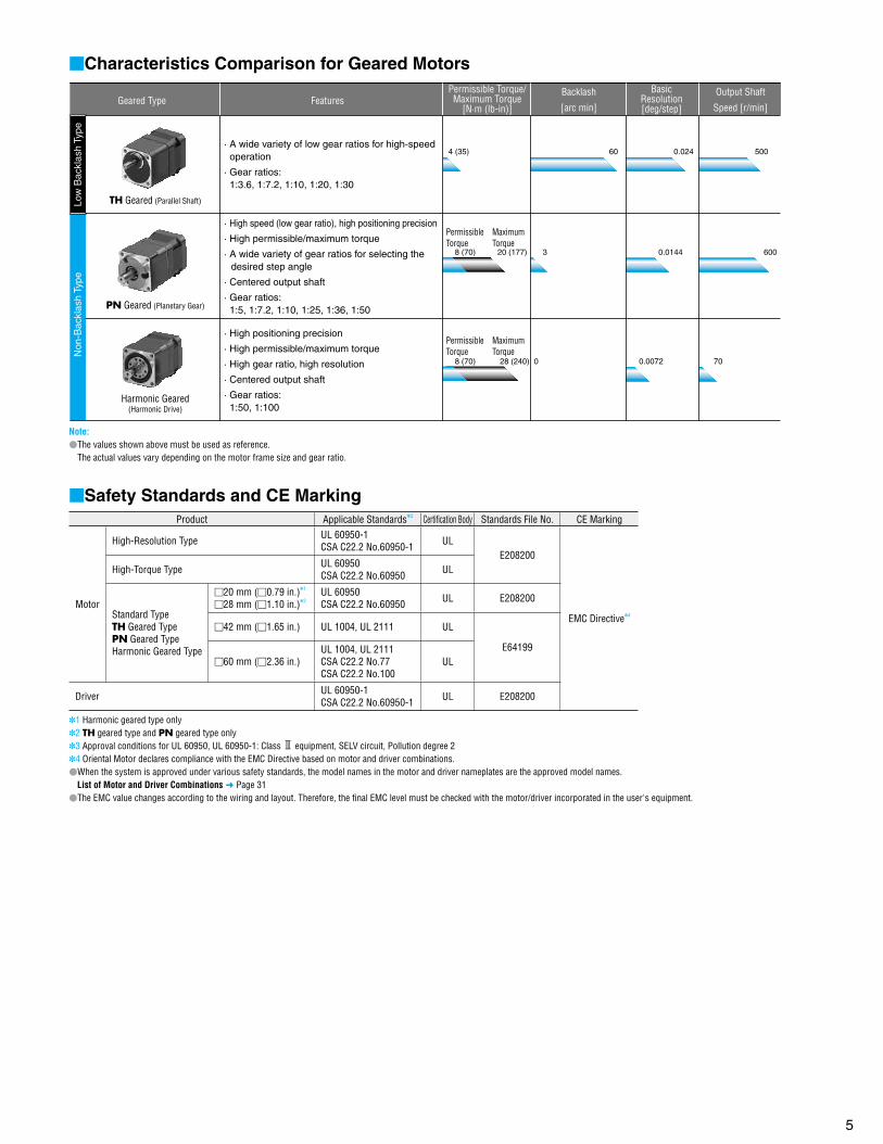
Characteristics Comparison for Geared Motors
TH Geared (Parallel Shaft)
PN Geared (Planetary Gear)
Harmonic Geared(Harmonic Drive)
500
600
70
0.024
0.0144
0.00720
3
60
8 (70) 20 (177)
28 (240)8 (70)
4 (35)
Non
-Bac
klas
h Ty
peLo
w B
ackl
ash
Type
· A wide variety of low gear ratios for high-speed operation
· Gear ratios: 1:3.6, 1:7.2, 1:10, 1:20, 1:30
· High speed (low gear ratio), high positioning precision
· High permissible/maximum torque
· A wide variety of gear ratios for selecting the desired step angle
· Centered output shaft
· Gear ratios: 1:5, 1:7.2, 1:10, 1:25, 1:36, 1:50
· High positioning precision
· High permissible/maximum torque
· High gear ratio, high resolution
· Centered output shaft
· Gear ratios: 1:50, 1:100
Geared Type FeaturesOutput Shaft
Speed [r/min]
Permissible Torque/Maximum Torque
[N·m (lb-in)]
BasicResolution[deg/step]
Backlash
[arc min]
PermissibleTorque
MaximumTorque
PermissibleTorque
MaximumTorque
Note: The values shown above must be used as reference.
The actual values vary depending on the motor frame size and gear ratio.
Safety Standards and CE MarkingProduct Applicable Standards3 Certifi cation Body Standards File No. CE Marking
Motor
High-Resolution Type UL 60950-1CSA C22.2 No.60950-1 UL
E208200
EMC Directive4
High-Torque Type UL 60950CSA C22.2 No.60950 UL
Standard TypeTH Geared TypePN Geared TypeHarmonic Geared Type
20 mm (0.79 in.)1
28 mm (1.10 in.)2UL 60950CSA C22.2 No.60950 UL E208200
42 mm (1.65 in.) UL 1004, UL 2111 UL
E6419960 mm (2.36 in.)
UL 1004, UL 2111CSA C22.2 No.77CSA C22.2 No.100
UL
Driver UL 60950-1CSA C22.2 No.60950-1 UL E208200
1 Harmonic geared type only2 TH geared type and PN geared type only3 Approval conditions for UL 60950, UL 60950-1: Class 3 equipment, SELV circuit, Pollution degree 24 Oriental Motor declares compliance with the EMC Directive based on motor and driver combinations.When the system is approved under various safety standards, the model names in the motor and driver nameplates are the approved model names.
List of Motor and Driver Combinations Page 31The EMC value changes according to the wiring and layout. Therefore, the final EMC level must be checked with the motor/driver incorporated in the user's equipment.
6
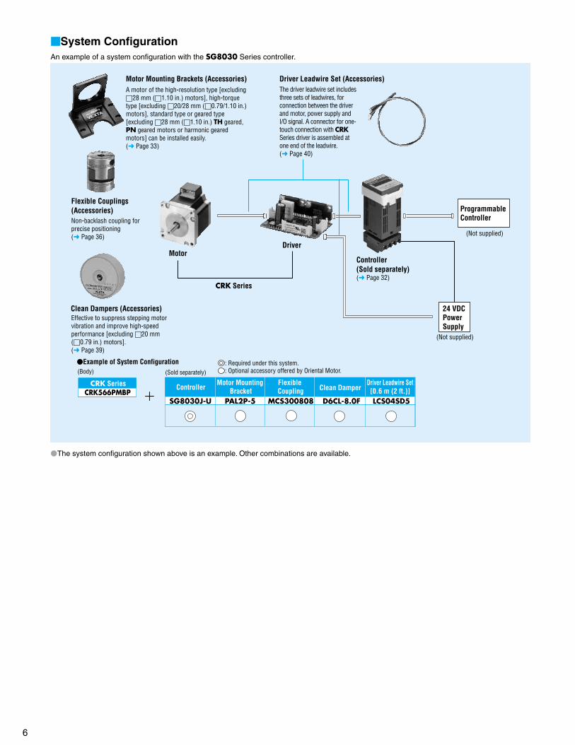
System ConfigurationAn example of a system configuration with the SG8030 Series controller.
Programmable Controller
(Not supplied)
Motor
CRK Series
Driver
Clean Dampers (Accessories)
Flexible Couplings(Accessories)Non-backlash coupling forprecise positioning ( Page 36)
24 VDC Power Supply
(Not supplied)
Controller (Sold separately)( Page 32)
Example of System Configuration
CRK SeriesCRK566PMBP
(Body) (Sold separately)
Controller
SG8030J-U
Flexible Coupling
MCS300808 D6CL-8.0F
Clean Damper
LCS04SD5
Driver Leadwire Set[0.6 m (2 ft.)]
Motor Mounting Bracket
PAL2P-5
Effective to suppress stepping motor vibration and improve high-speed performance [excluding 20 mm (0.79 in.) motors]. ( Page 39)
Driver Leadwire Set (Accessories)The driver leadwire set includes three sets of leadwires, for connection between the driver and motor, power supply and I/O signal. A connector for one-touch connection with CRK Series driver is assembled at one end of the leadwire. ( Page 40)
Motor Mounting Brackets (Accessories)A motor of the high-resolution type [excluding 28 mm (1.10 in.) motors], high-torque type [excluding 20/28 mm (0.79/1.10 in.) motors], standard type or geared type [excluding 28 mm (1.10 in.) TH geared, PN geared motors or harmonic geared motors] can be installed easily. ( Page 33)
: Required under this system.: Optional accessory offered by Oriental Motor.
The system configuration shown above is an example. Other combinations are available.
7
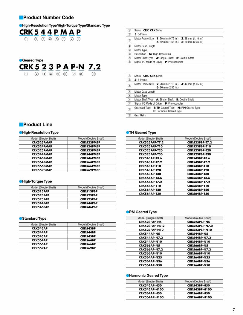
Product Line
High-Resolution Type
Model (Single Shaft) Model (Double Shaft)CRK523PMAP CRK523PMBPCRK524PMAP CRK524PMBPCRK525PMAP CRK525PMBPCRK544PMAP CRK544PMBPCRK546PMAP CRK546PMBPCRK564PMAP CRK564PMBPCRK566PMAP CRK566PMBPCRK569PMAP CRK569PMBP
High-Torque Type
Model (Single Shaft) Model (Double Shaft)CRK513PAP CRK513PBPCRK523PAP CRK523PBPCRK525PAP CRK525PBPCRK544PAP CRK544PBPCRK546PAP CRK546PBP
Standard Type
Model (Single Shaft) Model (Double Shaft)CRK543AP CRK543BPCRK544AP CRK544BPCRK545AP CRK545BPCRK564AP CRK564BPCRK566AP CRK566BPCRK569AP CRK569BP
TH Geared Type
Model (Single Shaft) Model (Double Shaft)CRK523PAP-T7.2 CRK523PBP-T7.2CRK523PAP-T10 CRK523PBP-T10CRK523PAP-T20 CRK523PBP-T20CRK523PAP-T30 CRK523PBP-T30CRK543AP-T3.6 CRK543BP-T3.6CRK543AP-T7.2 CRK543BP-T7.2CRK543AP-T10 CRK543BP-T10CRK543AP-T20 CRK543BP-T20CRK543AP-T30 CRK543BP-T30CRK564AP-T3.6 CRK564BP-T3.6CRK564AP-T7.2 CRK564BP-T7.2CRK564AP-T10 CRK564BP-T10CRK564AP-T20 CRK564BP-T20CRK564AP-T30 CRK564BP-T30
PN Geared Type
Model (Single Shaft) Model (Double Shaft)CRK523PAP-N5 CRK523PBP-N5CRK523PAP-N7.2 CRK523PBP-N7.2CRK523PAP-N10 CRK523PBP-N10CRK544AP-N5 CRK544BP-N5CRK544AP-N7.2 CRK544BP-N7.2CRK544AP-N10 CRK544BP-N10CRK566AP-N5 CRK566BP-N5CRK566AP-N7.2 CRK566BP-N7.2CRK566AP-N10 CRK566BP-N10CRK564AP-N25 CRK564BP-N25CRK564AP-N36 CRK564BP-N36CRK564AP-N50 CRK564BP-N50
Harmonic Geared Type
Model (Single Shaft) Model (Double Shaft)CRK543AP-H50 CRK543BP-H50CRK543AP-H100 CRK543BP-H100CRK564AP-H50 CRK564BP-H50CRK564AP-H100 CRK564BP-H100
Product Number Code
High-Resolution Type/High-Torque Type/Standard Type
q w e r t y u i
Geared Type
q w e r t y u i o
q Series CRK: CRK Seriesw 5: 5-Phase
eMotor Frame Size 1: 20 mm (0.79 in.) 2: 28 mm (1.10 in.) 4: 42 mm (1.65 in.) 6: 60 mm (2.36 in.)
r Motor Case Lengtht Motor Typey Resolution M: High-Resolutionu Motor Shaft Type A: Single Shaft B: Double Shafti Signal I/O Mode of Driver P: Photocoupler
q Series CRK: CRK Seriesw 5: 5-Phase
eMotor Frame Size 2: 28 mm (1.10 in.) 4: 42 mm (1.65 in.) 6: 60 mm (2.36 in.)
r Motor Case Lengtht Motor Typey Motor Shaft Type A: Single Shaft B: Double Shaftu Signal I/O Mode of Driver P: Photocoupler
iGearhead Type T: TH Geared Type N: PN Geared Type
H: Harmonic Geared Typeo Gear Ratio
8
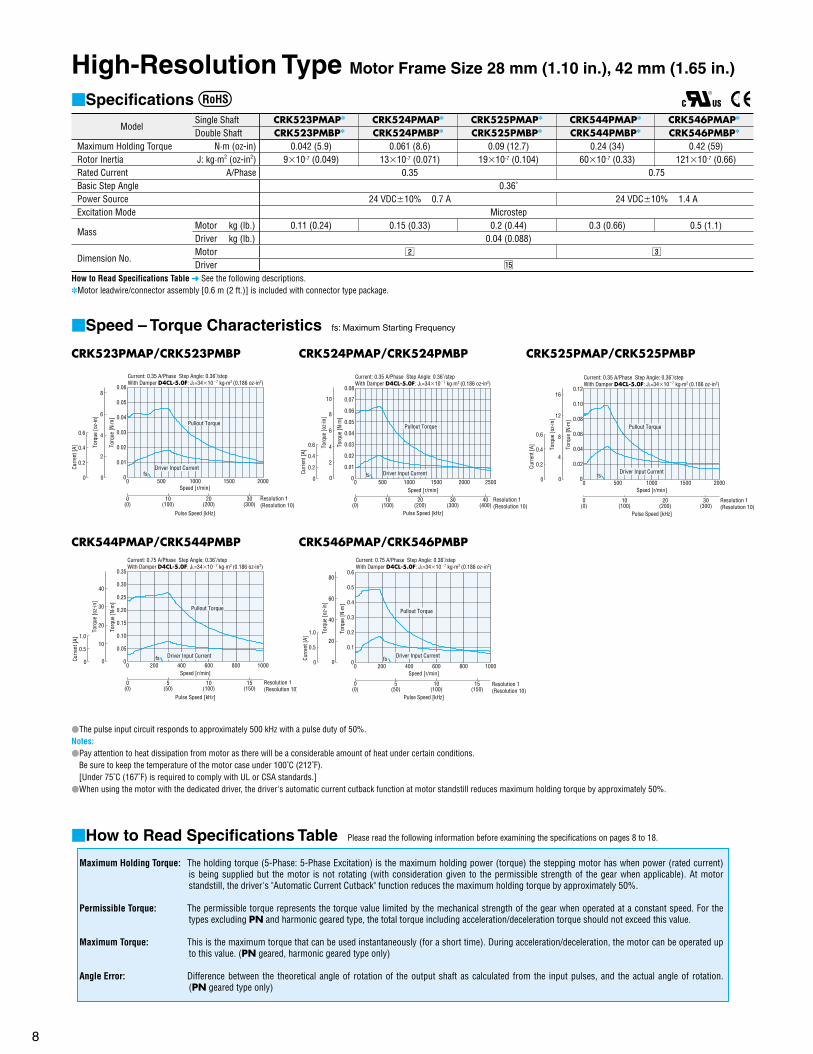
High-Resolution Type Motor Frame Size 28 mm (1.10 in.), 42 mm (1.65 in.)
Specifications
ModelSingle Shaft CRK523PMAP CRK524PMAP CRK525PMAP CRK544PMAP CRK546PMAP
Double Shaft CRK523PMBP CRK524PMBP CRK525PMBP CRK544PMBP CRK546PMBP
Maximum Holding Torque N·m (oz-in) 0.042 (5.9) 0.061 (8.6) 0.09 (12.7) 0.24 (34) 0.42 (59)Rotor Inertia J: kg·m2 (oz-in2) 910-7 (0.049) 1310-7 (0.071) 1910-7 (0.104) 6010-7 (0.33) 12110-7 (0.66)Rated Current A/Phase 0.35 0.75Basic Step Angle 0.36˚Power Source 24 VDC10% 0.7 A 24 VDC10% 1.4 AExcitation Mode Microstep
MassMotor kg (lb.) 0.11 (0.24) 0.15 (0.33) 0.2 (0.44) 0.3 (0.66) 0.5 (1.1)Driver kg (lb.) 0.04 (0.088)
Dimension No.Motor x c
Driver ⁄5
How to Read Specifications Table See the following descriptions.Motor leadwire/connector assembly [0.6 m (2 ft.)] is included with connector type package.
Speed – Torque Characteristics fs: Maximum Starting Frequency
The pulse input circuit responds to approximately 500 kHz with a pulse duty of 50%.Notes:Pay attention to heat dissipation from motor as there will be a considerable amount of heat under certain conditions.
Be sure to keep the temperature of the motor case under 100˚C (212˚F).[Under 75˚C (167˚F) is required to comply with UL or CSA standards.]
When using the motor with the dedicated driver, the driver's automatic current cutback function at motor standstill reduces maximum holding torque by approximately 50%.
How to Read Specifications Table Please read the following information before examining the specifications on pages 8 to 18.
Maximum Holding Torque: The holding torque (5-Phase: 5-Phase Excitation) is the maximum holding power (torque) the stepping motor has when power (rated current) is being supplied but the motor is not rotating (with consideration given to the permissible strength of the gear when applicable). At motor standstill, the driver's "Automatic Current Cutback" function reduces the maximum holding torque by approximately 50%.
Permissible Torque: The permissible torque represents the torque value limited by the mechanical strength of the gear when operated at a constant speed. For the types excluding PN and harmonic geared type, the total torque including acceleration/deceleration torque should not exceed this value.
Maximum Torque: This is the maximum torque that can be used instantaneously (for a short time). During acceleration/deceleration, the motor can be operated up to this value. (PN geared, harmonic geared type only)
Angle Error: Difference between the theoretical angle of rotation of the output shaft as calculated from the input pulses, and the actual angle of rotation. (PN geared type only)
CRK523PMAP/CRK523PMBP
0(0)
0
30(300)
20(200)
10(100)
1000500 200015000
0.06
0.05
0.04
0.03
0.01
0.02
0
0.2
0.6
0.4
fs
Torq
ue [N
·m]
0
4
6
8
2
Pullout Torque
Current: 0.35 A/Phase Step Angle: 0.36˚/stepWith Damper D4CL-5.0F: JL=34107 kg·m2 (0.186 oz-in2)
Driver Input Current
Pulse Speed [kHz]
Resolution 1(Resolution 10)
Speed [r/min]
Curr
ent [
A] Torq
ue [o
z-in
]
CRK524PMAP/CRK524PMBP
0(0)
0
40(400)
20(200)
10(100)
1000500 2500200015000
0.08
0.06
0.05
0.07
0.04
0.03
0.01
0.02
0
0.2
0.6
0.4
30(300)
Curr
ent [
A]
Resolution 1(Resolution 10)
Speed [r/min]
Pulse Speed [kHz]
Pullout Torque
Driver Input Current
Torq
ue [N
·m]
fs
Current: 0.35 A/Phase Step Angle: 0.36˚/stepWith Damper D4CL-5.0F: JL=34107 kg·m2 (0.186 oz-in2)
0
4
6
8
2
Torq
ue [o
z-in
]
10
CRK525PMAP/CRK525PMBP
0(0)
0
30(300)
20(200)
10(100)
1000500 200015000
0.12
0.10
0.08
0.06
0.02
0.04
0
0.2
0.6
0.4
fs
Current: 0.35 A/Phase Step Angle: 0.36˚/stepWith Damper D4CL-5.0F: JL=34107 kg·m2 (0.186 oz-in2)
Driver Input Current
Pullout Torque
Curr
ent [
A] Torq
ue [N
·m]
Pulse Speed [kHz]
Resolution 1(Resolution 10)
Speed [r/min]
0
8
12
16
4
Torq
ue [o
z-in
] CRK544PMAP/CRK544PMBP
0(0)
0
15(150)
10(100)
5(50)
400200 1000600 8000
0.35
0.30
0.25
0.20
0.15
0.05
0.10
0
0.5
1.0
Torq
ue [N
·m]
Curr
ent [
A]
fs
Pulse Speed [kHz]
Speed [r/min]
Current: 0.75 A/Phase Step Angle: 0.36˚/stepWith Damper D4CL-5.0F: JL=34107 kg·m2 (0.186 oz-in2)
Driver Input Current
Pullout Torque
Resolution 1(Resolution 10)
0
20
30
40
10
Torq
ue [o
z-in
]
CRK546PMAP/CRK546PMBP
0(0)
0
15(150)
10(100)
5(50)
400200 1000600 8000
0.6
0.5
0.4
0.3
0.1
0.2
Current: 0.75 A/Phase Step Angle: 0.36˚/step With Damper D4CL-5.0F: JL=34107 kg·m2 (0.186 oz-in2)
Torq
ue [N
·m]
0
0.5
1.0
Curr
ent [
A]
0
40
60
80
20
Torq
ue [o
z-in
]
Pullout Torque
Driver Input Currentfs
Pulse Speed [kHz]
Speed [r/min]
Resolution 1(Resolution 10)
9
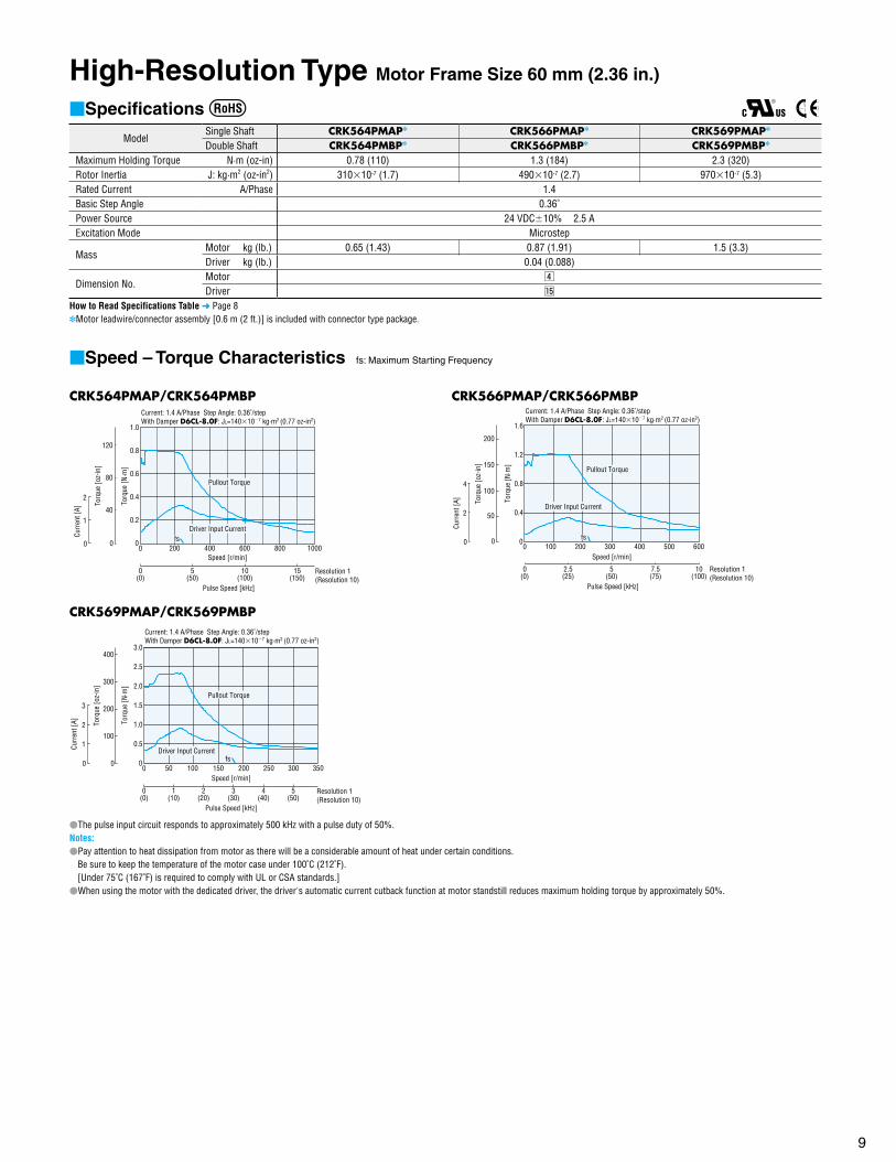
High-Resolution Type Motor Frame Size 60 mm (2.36 in.)
Specifications
ModelSingle Shaft CRK564PMAP CRK566PMAP CRK569PMAP
Double Shaft CRK564PMBP CRK566PMBP CRK569PMBP
Maximum Holding Torque N·m (oz-in) 0.78 (110) 1.3 (184) 2.3 (320)Rotor Inertia J: kg·m2 (oz-in2) 31010-7 (1.7) 49010-7 (2.7) 97010-7 (5.3)Rated Current A/Phase 1.4Basic Step Angle 0.36˚Power Source 24 VDC10% 2.5 AExcitation Mode Microstep
MassMotor kg (lb.) 0.65 (1.43) 0.87 (1.91) 1.5 (3.3)Driver kg (lb.) 0.04 (0.088)
Dimension No.Motor v
Driver ⁄5
How to Read Specifications Table Page 8Motor leadwire/connector assembly [0.6 m (2 ft.)] is included with connector type package.
Speed – Torque Characteristics fs: Maximum Starting Frequency
The pulse input circuit responds to approximately 500 kHz with a pulse duty of 50%.Notes:Pay attention to heat dissipation from motor as there will be a considerable amount of heat under certain conditions.
Be sure to keep the temperature of the motor case under 100˚C (212˚F).[Under 75˚C (167˚F) is required to comply with UL or CSA standards.]
When using the motor with the dedicated driver, the driver's automatic current cutback function at motor standstill reduces maximum holding torque by approximately 50%.
CRK564PMAP/CRK564PMBP
0(0)
0
15(150)
10(100)
5(50)
400200 1000600 8000
1.0
0.8
0.6
0.2
0.4
0
1
2
Current: 1.4 A/Phase Step Angle: 0.36˚/step With Damper D6CL-8.0F: JL=140107 kg·m2 (0.77 oz-in2)
Driver Input Current
Pullout Torque
Pulse Speed [kHz]
Resolution 1(Resolution 10)
Speed [r/min]
Torq
ue [N
·m]
Curr
ent [
A]
0
80
120
40
Torq
ue [o
z-in
]
fs
CRK569PMAP/CRK569PMBP
0(0)
0
5(50)
3(30)
2(20)
10050 350150 200 2500
3.0
1.0
2.0
2.5
0.5
1.5
0
2
1
3
1(10)
4(40)
300
Pullout Torque
Driver Input Current
Pulse Speed [kHz]
Resolution 1(Resolution 10)
Speed [r/min]
Torq
ue [N
·m]
Curr
ent [
A]
0
200
300
400
100
Torq
ue [o
z-in
]
fs
Current: 1.4 A/Phase Step Angle: 0.36˚/step With Damper D6CL-8.0F: JL=140107 kg·m2 (0.77 oz-in2)
CRK566PMAP/CRK566PMBP
0(0)
0
7.5(75)
5(50)
2.5(25)
200100 600300 400 5000
1.6
1.2
0.8
0.4
0
2
4
10(100)
Pulse Speed [kHz]
Resolution 1(Resolution 10)
Speed [r/min]
Torq
ue [N
·m]
Curr
ent [
A]
Pullout Torque
fs
Current: 1.4 A/Phase Step Angle: 0.36˚/step With Damper D6CL-8.0F: JL=140107 kg·m2 (0.77 oz-in2)
Driver Input Current
0
100
150
200
50
Torq
ue [o
z-in
]

10
High-Torque Type Motor Frame Size 20 mm (0.79 in.), 28 mm (1.10 in.)
Specifications
ModelSingle Shaft CRK513PAP CRK523PAP CRK525PAP
Double Shaft CRK513PBP CRK523PBP CRK525PBP
Maximum Holding Torque N·m (oz-in) 0.0231 (3.2) 0.048 (6.8) 0.078 (11)Rotor Inertia J: kg·m2 (oz-in2) 2.610-7 (0.0142) 910-7 (0.049) 1810-7 (0.098)Rated Current A/Phase 0.35Basic Step Angle 0.72˚Power Source 24 VDC10% 0.7 AExcitation Mode Microstep
MassMotor kg (lb.) 0.05 (0.11) 0.11 (0.24) 0.2 (0.44)Driver kg (lb.) 0.04 (0.088)
Dimension No.Motor z x
Driver ⁄5
How to Read Specifications Table Page 8Motor leadwire/connector assembly [0.6 m (2 ft.)] is included with connector type package.
Speed – Torque Characteristics fs: Maximum Starting Frequency
CRK513PAP/CRK513PBPCurrent: 0.35 A/Phase Step Angle: 0.72˚/stepLoad Inertia: JL=0 kg·m2
Pulse Speed [kHz]
0(0)
0
30(300)
20(200)
10(100)
Resolution 1(Resolution 10)
20001000 40003000Speed [r/min]
Torq
ue [N
·m]
0
0.030
0.025
0.020
0.015
0.005
0.010
0
0.5
1.0
Curr
ent [
A]
0
2
3
4
1
Torq
ue [o
z-in
]
Driver Input Current
Pullout Torque
fs
CRK525PAP/CRK525PBPCurrent: 0.35 A/Phase Step Angle: 0.72˚/stepWith Damper D4CL-5.0F: JL=34107 kg·m2 (0.186 oz-in2)
Pulse Speed [kHz]
0(0)
0
30(300)
20(200)
10(100)
Resolution 1(Resolution 10)
20001000 40003000Speed [r/min]
Torq
ue [N
·m]
0
0.10
0.08
0.06
0.04
0.02
0
1
2
Curr
ent [
A]
0
4
6
8
10
12
14
2
Torq
ue [o
z-in
]
Driver Input Current
Pullout Torque
fs
CRK523PAP/CRK523PBPCurrent: 0.35 A/Phase Step Angle: 0.72˚/stepWith Damper D4CL-5.0F: JL=34107 kg·m2 (0.186 oz-in2)
Pulse Speed [kHz]
0(0)
0
30(300)
20(200)
10(100)
Resolution 1(Resolution 10)
20001000 40003000Speed [r/min]
Torq
ue [N
·m]
0
0.06
0.05
0.04
0.03
0.01
0.02
0
0.5
1.0
Curr
ent [
A]
0
4
6
8
2
Torq
ue [o
z-in
]
Driver Input Current
Pullout Torque
fs
The pulse input circuit responds to approximately 500 kHz with a pulse duty of 50%.Notes:Pay attention to heat dissipation from motor as there will be a considerable amount of heat under certain conditions.
Be sure to keep the temperature of the motor case under 100˚C (212˚F).[Under 75˚C (167˚F) is required to comply with UL or CSA standards.]
When using the motor with the dedicated driver, the driver's automatic current cutback function at motor standstill reduces maximum holding torque by approximately 50%.
11
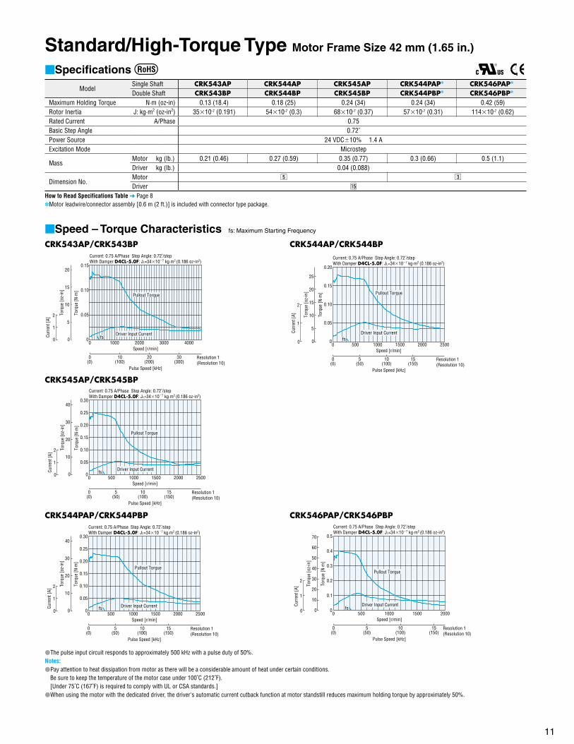
Standard/High-Torque Type Motor Frame Size 42 mm (1.65 in.)
Specifications
ModelSingle Shaft CRK543AP CRK544AP CRK545AP CRK544PAP CRK546PAP
Double Shaft CRK543BP CRK544BP CRK545BP CRK544PBP CRK546PBP
Maximum Holding Torque N·m (oz-in) 0.13 (18.4) 0.18 (25) 0.24 (34) 0.24 (34) 0.42 (59)Rotor Inertia J: kg·m2 (oz-in2) 3510-7 (0.191) 5410-7 (0.3) 6810-7 (0.37) 5710-7 (0.31) 11410-7 (0.62)Rated Current A/Phase 0.75Basic Step Angle 0.72˚Power Source 24 VDC10% 1.4 AExcitation Mode Microstep
MassMotor kg (lb.) 0.21 (0.46) 0.27 (0.59) 0.35 (0.77) 0.3 (0.66) 0.5 (1.1)Driver kg (lb.) 0.04 (0.088)
Dimension No.Motor b c
Driver ⁄5
How to Read Specifications Table Page 8Motor leadwire/connector assembly [0.6 m (2 ft.)] is included with connector type package.
Speed – Torque Characteristics fs: Maximum Starting Frequency
CRK543AP/CRK543BPCurrent: 0.75 A/Phase Step Angle: 0.72˚/step With Damper D4CL-5.0F: JL=34107 kg·m2 (0.186 oz-in2)
Pulse Speed [kHz]
0(0)
0
30(300)
20(200)
10(100)
Resolution 1(Resolution 10)
20001000 40003000Speed [r/min]
Torq
ue [N
·m]
0
0.15
0.10
0.05
0
1
2
Curr
ent [
A]
0
10
15
20
5
Torq
ue [o
z-in
]
fs
Pullout Torque
Driver Input Current
CRK545AP/CRK545BPCurrent: 0.75 A/Phase Step Angle: 0.72˚/step With Damper D4CL-5.0F: JL=34107 kg·m2 (0.186 oz-in2)
Pulse Speed [kHz]
0(0)
0
10(100)
5(50)
15(150)
Resolution 1(Resolution 10)
15001000500 25002000Speed [r/min]
Torq
ue [N
·m]
0
0.30
0.10
0.15
0.20
0.25
0.05
0
1
2
Curr
ent [
A]
0
20
30
40
10
Torq
ue [o
z-in
]
fs Driver Input Current
Pullout Torque
CRK544PAP/CRK544PBPCurrent: 0.75 A/Phase Step Angle: 0.72˚/step With Damper D4CL-5.0F: JL=34107 kg·m2 (0.186 oz-in2)
Pulse Speed [kHz]
0(0)
0
10(100)
5(50)
15(150)
Resolution 1(Resolution 10)
15001000500 25002000Speed [r/min]
Torq
ue [N
·m]
0
0.30
0.10
0.15
0.20
0.25
0.05
0
1
2
Curr
ent [
A]
0
20
30
40
10
Torq
ue [o
z-in
]
fs Driver Input Current
Pullout Torque
CRK544AP/CRK544BPCurrent: 0.75 A/Phase Step Angle: 0.72˚/step With Damper D4CL-5.0F: JL=34107 kg·m2 (0.186 oz-in2)
Pulse Speed [kHz]
0(0)
0
10(100)
5(50)
15(150)
Resolution 1(Resolution 10)
15001000500 25002000Speed [r/min]
Torq
ue [N
·m]
0
0.20
0.10
0.15
0.05
0
1
2
Curr
ent [
A]
0
5
10
15
20
25
Torq
ue [o
z-in
]
fsDriver Input Current
Pullout Torque
CRK546PAP/CRK546PBPCurrent: 0.75 A/Phase Step Angle: 0.72˚/step With Damper D4CL-5.0F: JL=34107 kg·m2 (0.186 oz-in2)
Pulse Speed [kHz]
0(0)
0
Resolution 1(Resolution 10)
15001000500 2000Speed [r/min]
Torq
ue [N
·m]
0
0.5
0.1
0.2
0.3
0.4
0
1
2
10(100)
15(150)
5(50)
Curr
ent [
A]
0
20
30
40
50
60
70
10
Torq
ue [o
z-in
]
fsDriver Input Current
Pullout Torque
The pulse input circuit responds to approximately 500 kHz with a pulse duty of 50%.Notes:Pay attention to heat dissipation from motor as there will be a considerable amount of heat under certain conditions.
Be sure to keep the temperature of the motor case under 100˚C (212˚F).[Under 75˚C (167˚F) is required to comply with UL or CSA standards.]
When using the motor with the dedicated driver, the driver's automatic current cutback function at motor standstill reduces maximum holding torque by approximately 50%.

12
Standard Type Motor Frame Size 60 mm (2.36 in.)
Specifications
ModelSingle Shaft CRK564AP CRK566AP CRK569APDouble Shaft CRK564BP CRK566BP CRK569BP
Maximum Holding Torque N·m (oz-in) 0.42 (59) 0.83 (117) 1.66 (230)Rotor Inertia J: kg·m2 (oz-in2) 17510-7 (0.96) 28010-7 (1.53) 56010-7 (3.1)Rated Current A/Phase 1.4Basic Step Angle 0.72˚Power Source 24 VDC10% 2.5 AExcitation Mode Microstep
MassMotor kg (lb.) 0.6 (1.32) 0.8 (1.76) 1.3 (2.9)Driver kg (lb.) 0.04 (0.088)
Dimension No.Motor n
Driver ⁄5
How to Read Specifications Table Page 8
Speed – Torque Characteristics fs: Maximum Starting Frequency
CRK564AP/CRK564BPCurrent: 1.4 A/Phase Step Angle: 0.72˚/step With Damper D6CL-8.0F: JL=140107 kg·m2 (0.77 oz-in2)
Pulse Speed [kHz]
0(0)
0
10(100)
5(50)
15(150)
Resolution 1(Resolution 10)
15001000500 25002000Speed [r/min]
Torq
ue [N
·m]
0
0.5
0.2
0.3
0.4
0.1
0
2
4
Curr
ent [
A]
0
20
30
40
50
60
70
10
Torq
ue [o
z-in
]
fs Driver Input Current
Pullout Torque
CRK569AP/CRK569BPCurrent: 1.4 A/Phase Step Angle: 0.72˚/step With Damper D6CL-8.0F: JL=140107 kg·m2 (0.77 oz-in2)
Pulse Speed [kHz]
0(0)
0
1(10)
Resolution 1(Resolution 10)
300200100 500400Speed [r/min]
Torq
ue [N
·m]
0
2.0
0.5
1.0
1.5
0
2
4
2(20)
3(30)
4(40)
Curr
ent [
A]
0
50
100
150
200
250
Torq
ue [o
z-in
]
fsDriver Input Current
Pullout Torque
CRK566AP/CRK566BPCurrent: 1.4 A/Phase Step Angle: 0.72˚/step With Damper D6CL-8.0F: JL=140107 kg·m2 (0.77 oz-in2)
Pulse Speed [kHz]
0(0)
0
5(50)
2.5(25)
Resolution 1(Resolution 10)
600400200 1000800Speed [r/min]
Torq
ue [N
·m]
0
1.2
0.4
0.6
0.8
1.0
0.2
0
1
2
7.5(75)
Curr
ent [
A]
0
80
120
160
40To
rque
[oz-
in]
fsDriver Input Current
Pullout Torque
The pulse input circuit responds to approximately 500 kHz with a pulse duty of 50%.Notes:Pay attention to heat dissipation from motor as there will be a considerable amount of heat under certain conditions.
Be sure to keep the temperature of the motor case under 100˚C (212˚F).[Under 75˚C (167˚F) is required to comply with UL or CSA standards.]
When using the motor with the dedicated driver, the driver's automatic current cutback function at motor standstill reduces maximum holding torque by approximately 50%.
13
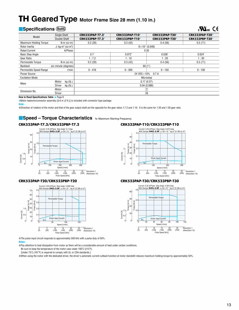
TH Geared Type Motor Frame Size 28 mm (1.10 in.)
Specifications
ModelSingle Shaft CRK523PAP-T7.2 CRK523PAP-T10 CRK523PAP-T20 CRK523PAP-T30
Double Shaft CRK523PBP-T7.2 CRK523PBP-T10 CRK523PBP-T20 CRK523PBP-T30
Maximum Holding Torque N·m (oz-in) 0.2 (28) 0.3 (42) 0.4 (56) 0.5 (71)Rotor Inertia J: kg·m2 (oz-in2) 910-7 (0.049)Rated Current A/Phase 0.35Basic Step Angle 0.1˚ 0.072˚ 0.036˚ 0.024˚Gear Ratio 1 : 7.2 1 : 10 1 : 20 1 : 30Permissible Torque N·m (oz-in) 0.2 (28) 0.3 (42) 0.4 (56) 0.5 (71)Backlash arc minute (degrees) 60 (1˚)Permissible Speed Range r/min 0416 0300 0150 0100Power Source 24 VDC10% 0.7 AExcitation Mode Microstep
MassMotor kg (lb.) 0.17 (0.37)Driver kg (lb.) 0.04 (0.088)
Dimension No.Motor m
Driver ⁄5
How to Read Specifications Table Page 8Motor leadwire/connector assembly [0.6 m (2 ft.)] is included with connector type package. Note:Direction of rotation of the motor and that of the gear output shaft are the opposite for the gear ratios 1:7.2 and 1:10. It is the same for 1:20 and 1:30 gear ratio.
Speed – Torque Characteristics fs: Maximum Starting Frequency
CRK523PAP-T7.2/CRK523PBP-T7.2Current: 0.35 A/Phase Step Angle: 0.1˚/step With Damper D4CL-5.0F: JL=34107 kg·m2 (0.186 oz-in2)
0
0.3
0.1
0.2
Pulse Speed [kHz]
0(0)
20(200)
10(100)
15(150)
5(50)
Resolution 1(Resolution 10)
300 400200100Speed [r/min]
0
25(250)
Torq
ue [N
·m]
0
0.5
1.0
Curr
ent [
A]
0
20
30
40
10
Torq
ue [o
z-in
]
fsDriver Input Current
Permissible Torque
CRK523PAP-T20/CRK523PBP-T20Current: 0.35 A/Phase Step Angle: 0.036˚/step With Damper D4CL-5.0F: JL=34107 kg·m2 (0.186 oz-in2)
Torq
ue [N
·m]
0
0.5
0.4
0.1
0.3
0.2
0
0.5
1.0
Curr
ent [
A]
Pulse Speed [kHz]
0(0)
20(200)
10(100)
15(150)
5(50)
Resolution 1(Resolution 10)
100 15050Speed [r/min]
0
25(250)
0
20
30
40
50
60
70
10
Torq
ue [o
z-in
]
fsDriver Input Current
Permissible Torque
CRK523PAP-T10/CRK523PBP-T10Current: 0.35 A/Phase Step Angle: 0.072˚/step With Damper D4CL-5.0F: JL=34107 kg·m2 (0.186 oz-in2)
0 100 200 300Speed [r/min]
Torq
ue [N
·m]
0
0.4
0.3
0.2
0.1
0
1
2
Curr
ent [
A]
Pulse Speed [kHz]
0(0)
Resolution 1(Resolution 10)
5(50)
10(100)
15(150)
20(200)
25(250)
0
10
20
30
40
50
Torq
ue [o
z-in
]
fs
Driver Input Current
Permissible Torque
CRK523PAP-T30/CRK523PBP-T30Current: 0.35 A/Phase Step Angle: 0.024˚/stepWith Damper D4CL-5.0F: JL=34107 kg·m2 (0.186 oz-in2)
Torq
ue [N
·m]
0
0.6
0.2
0.4
0
0.5
1.0
Curr
ent [
A]
Pulse Speed [kHz]
0(0)
20(200)
10(100)
15(150)
5(50)
Resolution 1(Resolution 10)
1008060 1204020Speed [r/min]
0
25(250)
0
40
60
80
20
Torq
ue [o
z-in
]
fs Driver Input Current
Permissible Torque
The pulse input circuit responds to approximately 500 kHz with a pulse duty of 50%.Notes:Pay attention to heat dissipation from motor as there will be a considerable amount of heat under certain conditions.
Be sure to keep the temperature of the motor case under 100˚C (212˚F).[Under 75˚C (167˚F) is required to comply with UL or CSA standards.]
When using the motor with the dedicated driver, the driver's automatic current cutback function at motor standstill reduces maximum holding torque by approximately 50%.
14
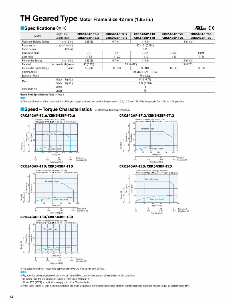
TH Geared Type Motor Frame Size 42 mm (1.65 in.)
Specifications
ModelSingle Shaft CRK543AP-T3.6 CRK543AP-T7.2 CRK543AP-T10 CRK543AP-T20 CRK543AP-T30Double Shaft CRK543BP-T3.6 CRK543BP-T7.2 CRK543BP-T10 CRK543BP-T20 CRK543BP-T30
Maximum Holding Torque N·m (lb-in) 0.35 (3) 0.7 (6.1) 1 (8.8) 1.5 (13.2)Rotor Inertia J: kg·m2 (oz-in2) 3510-7 (0.191)Rated Current A/Phase 0.75Basic Step Angle 0.2˚ 0.1˚ 0.072˚ 0.036˚ 0.024˚Gear Ratio 1 : 3.6 1 : 7.2 1 : 10 1 : 20 1 : 30Permissible Torque N·m (lb-in) 0.35 (3) 0.7 (6.1) 1 (8.8) 1.5 (13.2)Backlash arc minute (degrees) 45 (0.75˚) 25 (0.417˚) 15 (0.25˚)Permissible Speed Range r/min 0500 0250 0180 090 060Power Source 24 VDC10% 1.4 AExcitation Mode Microstep
MassMotor kg (lb.) 0.35 (0.77)Driver kg (lb.) 0.04 (0.088)
Dimension No.Motor ,
Driver ⁄5
How to Read Specifications Table Page 8Note:Direction of rotation of the motor and that of the gear output shaft are the same for the gear ratios 1:3.6, 1:7.2 and 1:10. It is the opposite for 1:20 and 1:30 gear ratio.
Speed – Torque Characteristics fs: Maximum Starting Frequency
CRK543AP-T3.6/CRK543BP-T3.6Current: 0.75 A/Phase Step Angle: 0.2˚/step With Damper D4CL-5.0F: JL=34107 kg·m2 (0.186 oz-in2)
Pulse Speed [kHz]
0(0)
0 100 200 300 400 500
15(150)
10(100)
5(50)
Resolution 1(Resolution 10)
600Speed [r/min]
Torq
ue [N
·m]
0
0.5
0.4
0.3
0.1
0.2
0
1
2
Curr
ent [
A]
0
2
3
4
1
Torq
ue [l
b-in
]
fsDriver Input Current
Permissible Torque
CRK543AP-T10/CRK543BP-T10Current: 0.75 A/Phase Step Angle: 0.072˚/step With Damper D4CL-5.0F: JL=34107 kg·m2 (0.186 oz-in2)
Pulse Speed [kHz]
0(0)
0 40 80 120 160
10(100)
5(50)
Resolution 1(Resolution 10)
200Speed [r/min]
Torq
ue [N
·m]
0
1.5
1.0
0.5
15(150)
0
1
2
Curr
ent [
A]
0
8
12
4
Torq
ue [l
b-in
]
fsDriver Input Current
Permissible Torque
CRK543AP-T30/CRK543BP-T30Current: 0.75 A/Phase Step Angle: 0.024˚/step With Damper D4CL-5.0F: JL=34107 kg·m2 (0.186 oz-in2)
Pulse Speed [kHz]
0(0)
0 10 20 30 40 50 60
15(150)
10(100)
5(50)
Resolution 1(Resolution 10)
70Speed [r/min]
0
2.0
1.5
1.0
0.5
0
1
2
Curr
ent [
A] Torq
ue [N
·m]
0
10
15
5
Torq
ue [l
b-in
]
fsDriver Input Current
Permissible Torque
CRK543AP-T7.2/CRK543BP-T7.2Current: 0.75 A/Phase Step Angle: 0.1˚/step With Damper D4CL-5.0F: JL=34107 kg·m2 (0.186 oz-in2)
Pulse Speed [kHz]
0(0)
0 50 100 150 200
10(100)
5(50)
Resolution 1(Resolution 10)
250Speed [r/min]
Torq
ue [N
·m]
0
1.0
0.8
0.6
0.4
0.2
0
1
2
15(150)
Curr
ent [
A]
0
4
6
8
2
Torq
ue [l
b-in
]
fsDriver Input Current
Permissible Torque
CRK543AP-T20/CRK543BP-T20Current: 0.75 A/Phase Step Angle: 0.036˚/step With Damper D4CL-5.0F: JL=34107 kg·m2 (0.186 oz-in2)
Pulse Speed [kHz]
0(0)
0 20 40 60 80
10(100)
5(50)
Resolution 1(Resolution 10)
100Speed [r/min]
0
2.0
1.5
1.0
0.5
0
1
2
15(150)
Curr
ent [
A] Torq
ue [N
·m]
0
10
15
5
Torq
ue [l
b-in
]
fsDriver Input Current
Permissible Torque
The pulse input circuit responds to approximately 500 kHz with a pulse duty of 50%.Notes:Pay attention to heat dissipation from motor as there will be a considerable amount of heat under certain conditions.
Be sure to keep the temperature of the motor case under 100˚C (212˚F).[Under 75˚C (167˚F) is required to comply with UL or CSA standards.]
When using the motor with the dedicated driver, the driver's automatic current cutback function at motor standstill reduces maximum holding torque by approximately 50%.
15
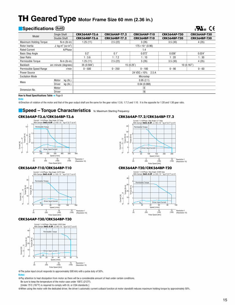
TH Geared Type Motor Frame Size 60 mm (2.36 in.)
Specifications
ModelSingle Shaft CRK564AP-T3.6 CRK564AP-T7.2 CRK564AP-T10 CRK564AP-T20 CRK564AP-T30Double Shaft CRK564BP-T3.6 CRK564BP-T7.2 CRK564BP-T10 CRK564BP-T20 CRK564BP-T30
Maximum Holding Torque N·m (lb-in) 1.25 (11) 2.5 (22) 3 (26) 3.5 (30) 4 (35)Rotor Inertia J: kg·m2 (oz-in2) 17510-7 (0.96)Rated Current A/Phase 1.4Basic Step Angle 0.2˚ 0.1˚ 0.072˚ 0.036˚ 0.024˚Gear Ratio 1 : 3.6 1 : 7.2 1 : 10 1 : 20 1 : 30Permissible Torque N·m (lb-in) 1.25 (11) 2.5 (22) 3 (26) 3.5 (30) 4 (35)Backlash arc minute (degrees) 35 (0.584˚) 15 (0.25˚) 10 (0.167˚)Permissible Speed Range r/min 0500 0250 0180 090 060Power Source 24 VDC10% 2.5 AExcitation Mode Microstep
MassMotor kg (lb.) 0.95 (2.1)Driver kg (lb.) 0.04 (0.088)
Dimension No.Motor .
Driver ⁄5
How to Read Specifications Table Page 8Note:Direction of rotation of the motor and that of the gear output shaft are the same for the gear ratios 1:3.6, 1:7.2 and 1:10. It is the opposite for 1:20 and 1:30 gear ratio.
Speed – Torque Characteristics fs: Maximum Starting Frequency
CRK564AP-T3.6/CRK564BP-T3.6Current: 1.4 A/Phase Step Angle: 0.2˚/step With Damper D6CL-8.0F: JL=140107 kg·m2 (0.77 oz-in2)
Torq
ue [N
·m]
0
1.5
1.0
0.5
0
1
3
2
Curr
ent [
A]
Pulse Speed [kHz]
0(0)
0 100 200 300 400 500
15(150)
10(100)
5(50)
Resolution 1(Resolution 10)
600Speed [r/min]
0
8
12
4
Torq
ue [l
b-in
]
fsDriver Input Current
Permissible Torque
CRK564AP-T10/CRK564BP-T10Current: 1.4 A/Phase Step Angle: 0.072˚/step With Damper D6CL-8.0F: JL=140107 kg·m2 (0.77 oz-in2)
Torq
ue [N
·m]
0
4
3
2
1
0
2
4
Curr
ent [
A]
Pulse Speed [kHz]
0(0)
0 40 80 120 160
10(100)
5(50)
Resolution 1(Resolution 10)
200Speed [r/min]
15(150)
0
20
30
10
Torq
ue [l
b-in
]
fsDriver Input Current
Permissible Torque
CRK564AP-T30/CRK564BP-T30Current: 1.4 A/Phase Step Angle: 0.024˚/step With Damper D6CL-8.0F: JL=140107 kg·m2 (0.77 oz-in2)
Torq
ue [N
·m]
0
5
4
3
2
1
0
2
4
Curr
ent [
A]
Pulse Speed [kHz]
0(0)
0 10 20 30 40 50 60
15(150)
10(100)
5(50)
Resolution 1(Resolution 10)
70Speed [r/min]
0
20
30
40
10
Torq
ue [l
b-in
]
fs
Driver Input Current
Permissible Torque
CRK564AP-T7.2/CRK564BP-T7.2Current: 1.4 A/Phase Step Angle: 0.1˚/step With Damper D6CL-8.0F: JL=140107 kg·m2 (0.77 oz-in2)
Torq
ue [N
·m]
0
3
2
1
0
1
3
2
Curr
ent [
A]
Pulse Speed [kHz]
0(0)
0 50 100 150 200
10(100)
5(50)
Resolution 1(Resolution 10)
250Speed [r/min]
15(150)
0
5
10
15
20
25To
rque
[lb-
in]
fs
Driver Input Current
Permissible Torque
CRK564AP-T20/CRK564BP-T20Current: 1.4 A/Phase Step Angle: 0.036˚/step With Damper D6CL-8.0F: JL=140107 kg·m2 (0.77 oz-in2)
Torq
ue [N
·m]
0
5
4
3
2
1
0
2
4
Curr
ent [
A]
Pulse Speed [kHz]
0(0)
0 20 40 60 80
10(100)
5(50)
Resolution 1(Resolution 10)
100Speed [r/min]
15(150)
0
20
30
40
10
Torq
ue [l
b-in
]
fs Driver Input Current
Permissible Torque
The pulse input circuit responds to approximately 500 kHz with a pulse duty of 50%.Notes:Pay attention to heat dissipation from motor as there will be a considerable amount of heat under certain conditions.
Be sure to keep the temperature of the motor case under 100˚C (212˚F).[Under 75˚C (167˚F) is required to comply with UL or CSA standards.]
When using the motor with the dedicated driver, the driver's automatic current cutback function at motor standstill reduces maximum holding torque by approximately 50%.

16
PN Geared Type Motor Frame Size 28 mm (1.10 in.), 42 mm (1.65 in.)
Specifications
ModelSingle Shaft CRK523PAP-N51 CRK523PAP-N7.21 CRK523PAP-N101 CRK544AP-N5 CRK544AP-N7.2 CRK544AP-N10Double Shaft CRK523PBP-N51 CRK523PBP-N7.21 CRK523PBP-N101 CRK544BP-N5 CRK544BP-N7.2 CRK544BP-N10
Maximum Holding Torque N·m(CRK523 : oz-in/CRK544 : lb-in) 0.2 (28) 0.3 (42) 0.4 (56) 0.8 (7) 1.2 (10.6) 1.5 (13.2)
Rotor Inertia J: kg·m2 (oz-in2) 910-7 (0.049) 5410-7 (0.3)Rated Current A/Phase 0.35 0.75Basic Step Angle 0.144˚ 0.1˚ 0.072˚ 0.144˚ 0.1˚ 0.072˚Gear Ratio 1 : 5 1 : 7.2 1 : 10 1 : 5 1 : 7.2 1 : 10
Permissible Torque N·m(CRK523 : oz-in/CRK544 : lb-in) 0.2 (28) 0.3 (42) 0.4 (56) 0.8 (7) 1.2 (10.6) 1.5 (13.2)
Maximum Torque2 N·m(CRK523 : oz-in/CRK544 : lb-in) 0.5 (71) 1.5 (13.2) 2 (17.7)
Backlash arc minute (degrees) 3 (0.05˚) 2 (0.034˚)Angle Error arc minute (degrees) 6 (0.1˚)Permissible Speed Range r/min 0600 0416 0300 0600 0416 0300Power Source 24 VDC10% 0.7 A 24 VDC10% 1.4 AExcitation Mode Microstep
MassMotor kg (lb.) 0.25 (0.55) 0.56 (1.23)Driver kg (lb.) 0.04 (0.088)
Dimension No.Motor ⁄0 ⁄1
Driver ⁄5
How to Read Specifications Table Page 81 Motor leadwire/connector assembly [0.6 m (2 ft.)] is included with connector type package. 2 The value of Maximum Torque is for gear. For output torque for geared motor, see the Speed - Torque Characteristics.Note:Direction of rotation of the motor and that of the gear output shaft are the same.
Speed – Torque Characteristics fs: Maximum Starting Frequency
CRK523PAP-N5/CRK523PBP-N5Current: 0.35 A/Phase Step Angle: 0.144˚/step With Damper D4CL-5.0F: JL=34107 kg·m2 (0.186 oz-in2)
Torq
ue [N
·m]
0
0.3
0.1
0.2
Pulse Speed [kHz]
0(0)
20(200)
10(100)
15(150)
5(50)
Resolution 1(Resolution 10)
600300 400 500200100Speed [r/min]
00
0.5
1.0
Curr
ent [
A]
0
20
30
40
10
Torq
ue [o
z-in
]
fsDriver Input Current
Permissible Torque
CRK523PAP-N7.2/CRK523PBP-N7.2Current: 0.35 A/Phase Step Angle: 0.1˚/step With Damper D4CL-5.0F: JL=34107 kg·m2 (0.186 oz-in2)
Torq
ue [N
·m]
0
0.4
0.3
0.1
0.2
0
1
2
Curr
ent [
A]
Pulse Speed [kHz]
0(0)
20(200)
10(100)
15(150)
5(50)
Resolution 1(Resolution 10)
300 400200100Speed [r/min]
00
10
20
30
40
50
Torq
ue [o
z-in
]
fs
Driver Input Current
Permissible Torque
CRK523PAP-N10/CRK523PBP-N10Current: 0.35 A/Phase Step Angle: 0.072˚/step With Damper D4CL-5.0F: JL=34107 kg·m2 (0.186 oz-in2)
Pulse Speed [kHz]
0(0)
0
Resolution 1(Resolution 10)
15010050 200 300250Speed [r/min]
Torq
ue [N
·m]
0
0.6
0.2
0.4
5(50)
10(100)
15(150)
20(200)
0
0.5
1.0
Curr
ent [
A]
0
40
60
80
20
Torq
ue [o
z-in
]
fsDriver Input Current
Permissible Torque
The pulse input circuit responds to approximately 500 kHz with a pulse duty of 50%.Notes:Pay attention to heat dissipation from motor as there will be a considerable amount of heat under certain conditions.
Be sure to keep the temperature of the motor case under 100˚C (212˚F).[Under 75˚C (167˚F) is required to comply with UL or CSA standards.]
When using the motor with the dedicated driver, the driver's automatic current cutback function at motor standstill reduces maximum holding torque by approximately 50%.
CRK544AP-N5/CRK544BP-N5Current: 0.75 A/Phase Step Angle: 0.144˚/step With Damper D4CL-5.0F: JL=34107 kg·m2 (0.186 oz-in2)
Torq
ue [N
·m]
0
1.0
0.6
0.4
0.8
0.2
0
1
2
Curr
ent [
A]
Pulse Speed [kHz]
0(0)
20(200)
10(100)
15(150)
5(50)
Resolution 1(Resolution 10)
600300 400 500200100Speed [r/min]
00
4
6
8
2
Torq
ue [l
b-in
]
fs Driver Input Current
Permissible Torque
CRK544AP-N7.2/CRK544BP-N7.2Current: 0.75 A/Phase Step Angle: 0.1˚/step With Damper D4CL-5.0F: JL=34107 kg·m2 (0.186 oz-in2)
Torq
ue [N
·m]
0
1.5
0.5
1.0
0
1
2
Curr
ent [
A]
Pulse Speed [kHz]
0(0)
20(200)
10(100)
15(150)
5(50)
Resolution 1(Resolution 10)
300 400200100Speed [r/min]
00
8
12
4
Torq
ue [l
b-in
]
fs Driver Input Current
Permissible Torque
CRK544AP-N10/CRK544BP-N10Current: 0.75 A/Phase Step Angle: 0.072˚/step With Damper D4CL-5.0F: JL=34107 kg·m2 (0.186 oz-in2)
Pulse Speed [kHz]
0(0)
0
Resolution 1(Resolution 10)
15010050 200 300250Speed [r/min]
5(50)
10(100)
15(150)
20(200)
0
2.0
1.5
1.0
0.5
0
2
4
Curr
ent [
A] Torq
ue [N
·m]
0
10
15
5
Torq
ue [l
b-in
]
fs
Driver Input Current
PermissibleTorque

17
PN Geared Type Motor Frame Size 60 mm (2.36 in.)
Specifications
ModelSingle Shaft CRK566AP-N5 CRK566AP-N7.2 CRK566AP-N10 CRK564AP-N25 CRK564AP-N36 CRK564AP-N50Double Shaft CRK566BP-N5 CRK566BP-N7.2 CRK566BP-N10 CRK564BP-N25 CRK564BP-N36 CRK564BP-N50
Maximum Holding Torque N·m (lb-in) 3.5 (30) 4 (35) 5 (44) 8 (70)Rotor Inertia J: kg·m2 (oz-in2) 28010-7 (1.53) 17510-7 (0.96)Rated Current A/Phase 1.4Basic Step Angle 0.144˚ 0.1˚ 0.072˚ 0.0288˚ 0.02˚ 0.0144˚Gear Ratio 1 : 5 1 : 7.2 1 : 10 1 : 25 1 : 36 1 : 50Permissible Torque N·m (lb-in) 3.5 (30) 4 (35) 5 (44) 8 (70)Maximum Torque N·m (lb-in) 7 (61) 9 (79) 11 (97) 16 (141) 20 (177)Backlash arc minute (degrees) 2 (0.034˚) 3 (0.05˚)Angle Error arc minute (degrees) 5 (0.084˚)Permissible Speed Range r/min 0600 0416 0300 0120 083 060Power Source 24 VDC10% 2.5 AExcitation Mode Microstep
MassMotor kg (lb.) 1.5 (3.3)Driver kg (lb.) 0.04 (0.088)
Dimension No.Motor ⁄2
Driver ⁄5
How to Read Specifications Table Page 8The value of Maximum Torque is for gear. For output torque for geared motor, see the Speed - Torque Characteristics. Note:Direction of rotation of the motor and that of the gear output shaft are the same.
Speed – Torque Characteristics fs: Maximum Starting Frequency
CRK566AP-N5/CRK566BP-N5Current: 1.4 A/Phase Step Angle: 0.144˚/step With Damper D6CL-8.0F: JL=140107 kg·m2 (0.77 oz-in2)
Pulse Speed [kHz]
0(0)
0
Resolution 1(Resolution 10)
200100 300 500400Speed [r/min]
Torq
ue [N
·m]
0
5
2
3
4
1
0
2
4
5(50)
Curr
ent [
A]
10(100)
15(150)
0
20
30
40
10
Torq
ue [l
b-in
]
fs Driver Input Current
Permissible Torque
CRK566AP-N7.2/CRK566BP-N7.2Current: 1.4 A/Phase Step Angle: 0.1˚/step With Damper D6CL-8.0F: JL=140107 kg·m2 (0.77 oz-in2)
Pulse Speed [kHz]
0(0)
0
Resolution 1(Resolution 10)
200100 15050 250 350300Speed [r/min]
Torq
ue [N
·m]
0
8
4
6
2
0
2
4
5(50)
Curr
ent [
A]
10(100)
15(150)
0
40
60
20
Torq
ue [l
b-in
]
fs
Driver Input Current
Permissible Torque
CRK566AP-N10/CRK566BP-N10Current: 1.4 A/Phase Step Angle: 0.072˚/step With Damper D6CL-8.0F: JL=140107 kg·m2 (0.77 oz-in2)
Pulse Speed [kHz]
0(0)
0
Resolution 1(Resolution 10)
200100 15050 250 300Speed [r/min]
Torq
ue [N
·m]
0
10
8
4
6
2
0
2
4
5(50)
Curr
ent [
A]
10(100)
15(150)
20(200)
0
40
60
80
20
Torq
ue [l
b-in
]
fs
Permissible Torque
Driver Input Current
The pulse input circuit responds to approximately 500 kHz with a pulse duty of 50%.Notes:Pay attention to heat dissipation from motor as there will be a considerable amount of heat under certain conditions.
Be sure to keep the temperature of the motor case under 100˚C (212˚F).[Under 75˚C (167˚F) is required to comply with UL or CSA standards.]
When using the motor with the dedicated driver, the driver's automatic current cutback function at motor standstill reduces maximum holding torque by approximately 50%.
CRK564AP-N25/CRK564BP-N25Current: 1.4 A/Phase Step Angle: 0.0288˚/step With Damper D6CL-8.0F: JL=140107 kg·m2 (0.77 oz-in2)
Torq
ue [N
·m]
0
15
5
10
0
2.5
5.0
Curr
ent [
A]
Pulse Speed [kHz]
0(0)
20(200)
10(100)
15(150)
5(50)
Resolution 1(Resolution 10)
100 120 14080604020Speed [r/min]
00
80
120
40
Torq
ue [l
b-in
]
fs
PermissibleTorque
Driver Input Current
CRK564AP-N36/CRK564BP-N36Current: 1.4 A/Phase Step Angle: 0.02˚/step With Damper D6CL-8.0F: JL=140107 kg·m2 (0.77 oz-in2)
Pulse Speed [kHz]
0(0)
0
Resolution 1(Resolution 10)
20 40 8060Speed [r/min]
Torq
ue [N
·m]
0
20
10
15
5
0
4
8
5(50)
Curr
ent [
A]
10(100)
15(150)
20(200)
0
100
150
50
Torq
ue [l
b-in
]
fs
Driver Input Current
Permissible Torque
CRK564AP-N50/CRK564BP-N50Current: 1.4 A/Phase Step Angle: 0.0144˚/step With Damper D6CL-8.0F: JL=140107 kg·m2 (0.77 oz-in2)
Torq
ue [N
·m]
0
25
15
10
20
5
0
2
4
Curr
ent [
A]
Pulse Speed [kHz]
0(0)
20(200)
10(100)
15(150)
5(50)
Resolution 1(Resolution 10)
604020Speed [r/min]
00
100
150
200
50
Torq
ue [l
b-in
]
fs Driver Input Current
Permissible Torque
18
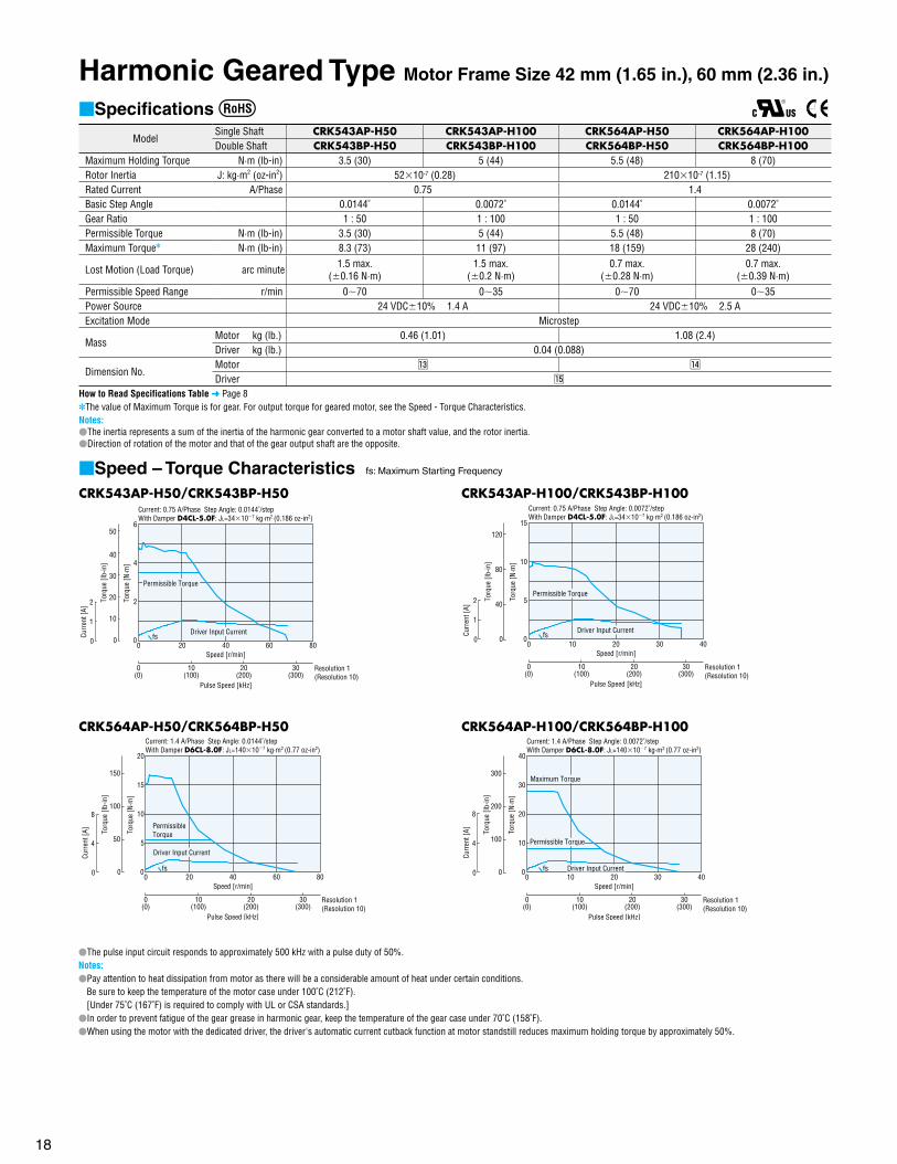
Harmonic Geared Type Motor Frame Size 42 mm (1.65 in.), 60 mm (2.36 in.)
Specifications
ModelSingle Shaft CRK543AP-H50 CRK543AP-H100 CRK564AP-H50 CRK564AP-H100Double Shaft CRK543BP-H50 CRK543BP-H100 CRK564BP-H50 CRK564BP-H100
Maximum Holding Torque N·m (lb-in) 3.5 (30) 5 (44) 5.5 (48) 8 (70)Rotor Inertia J: kg·m2 (oz-in2) 5210-7 (0.28) 21010-7 (1.15)Rated Current A/Phase 0.75 1.4Basic Step Angle 0.0144˚ 0.0072˚ 0.0144˚ 0.0072˚Gear Ratio 1 : 50 1 : 100 1 : 50 1 : 100Permissible Torque N·m (lb-in) 3.5 (30) 5 (44) 5.5 (48) 8 (70)Maximum Torque N·m (lb-in) 8.3 (73) 11 (97) 18 (159) 28 (240)
Lost Motion (Load Torque) arc minute 1.5 max.(0.16 N·m)
1.5 max.(0.2 N·m)
0.7 max.(0.28 N·m)
0.7 max.(0.39 N·m)
Permissible Speed Range r/min 070 035 070 035Power Source 24 VDC10% 1.4 A 24 VDC10% 2.5 AExcitation Mode Microstep
MassMotor kg (lb.) 0.46 (1.01) 1.08 (2.4)Driver kg (lb.) 0.04 (0.088)
Dimension No.Motor ⁄3 ⁄4
Driver ⁄5
How to Read Specifications Table Page 8The value of Maximum Torque is for gear. For output torque for geared motor, see the Speed - Torque Characteristics. Notes:The inertia represents a sum of the inertia of the harmonic gear converted to a motor shaft value, and the rotor inertia.Direction of rotation of the motor and that of the gear output shaft are the opposite.
Speed – Torque Characteristics fs: Maximum Starting Frequency
CRK543AP-H50/CRK543BP-H50Current: 0.75 A/Phase Step Angle: 0.0144˚/step With Damper D4CL-5.0F: JL=34107 kg·m2 (0.186 oz-in2)
Pulse Speed [kHz]
0(0)
0
20(200)
10(100)
Resolution 1(Resolution 10)
20 40 8060Speed [r/min]
Torq
ue [N
·m]
0
6
4
2
0
1
2
30(300)
Curr
ent [
A]
0
10
20
30
40
50
Torq
ue [l
b-in
]
fsDriver Input Current
Permissible Torque
CRK564AP-H50/CRK564BP-H50Current: 1.4 A/Phase Step Angle: 0.0144˚/step With Damper D6CL-8.0F: JL=140107 kg·m2 (0.77 oz-in2)
Pulse Speed [kHz]
0(0)
0
20(200)
10(100)
Resolution 1(Resolution 10)
20 40 8060Speed [r/min]
Torq
ue [N
·m]
0
20
15
10
5
0
4
8
30(300)
Curr
ent [
A]
0
100
150
50
Torq
ue [l
b-in
]
fs
Driver Input Current
PermissibleTorque
CRK543AP-H100/CRK543BP-H100Current: 0.75 A/Phase Step Angle: 0.0072˚/step With Damper D4CL-5.0F: JL=34107 kg·m2 (0.186 oz-in2)
Pulse Speed [kHz]
0(0)
0
20(200)
10(100)
Resolution 1(Resolution 10)
10 20 4030Speed [r/min]
Torq
ue [N
·m]
0
15
5
10
0
1
2
30(300)
Curr
ent [
A]
0
80
120
40
Torq
ue [l
b-in
]
fsDriver Input Current
Permissible Torque
CRK564AP-H100/CRK564BP-H100Current: 1.4 A/Phase Step Angle: 0.0072˚/step With Damper D6CL-8.0F: JL=140107 kg·m2 (0.77 oz-in2)
Pulse Speed [kHz]
0(0)
0
20(200)
10(100)
Resolution 1(Resolution 10)
10 20 4030Speed [r/min]
Torq
ue [N
·m]
0
40
20
30
10
0
4
8
30(300)
Curr
ent [
A]
0
200
300
100
Torq
ue [l
b-in
]
fs Driver Input Current
Permissible Torque
Maximum Torque
The pulse input circuit responds to approximately 500 kHz with a pulse duty of 50%.Notes:Pay attention to heat dissipation from motor as there will be a considerable amount of heat under certain conditions.
Be sure to keep the temperature of the motor case under 100˚C (212˚F).[Under 75˚C (167˚F) is required to comply with UL or CSA standards.]
In order to prevent fatigue of the gear grease in harmonic gear, keep the temperature of the gear case under 70˚C (158˚F).When using the motor with the dedicated driver, the driver's automatic current cutback function at motor standstill reduces maximum holding torque by approximately 50%.
19
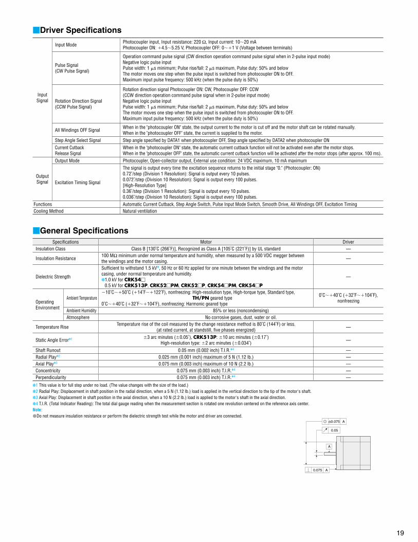
Driver Specifications
Input Signal
Input Mode Photocoupler input, Input resistance: 220 Ω, Input current: 1020 mAPhotocoupler ON: 4.55.25 V, Photocoupler OFF: 01 V (Voltage between terminals)
Pulse Signal(CW Pulse Signal)
Operation command pulse signal (CW direction operation command pulse signal when in 2-pulse input mode) Negative logic pulse inputPulse width: 1 s minimum; Pulse rise/fall: 2 s maximum, Pulse duty: 50% and belowThe motor moves one step when the pulse input is switched from photocoupler ON to OFF.Maximum input pulse frequency: 500 kHz (when the pulse duty is 50%)
Rotation Direction Signal(CCW Pulse Signal)
Rotation direction signal Photocoupler ON: CW, Photocoupler OFF: CCW(CCW direction operation command pulse signal when in 2-pulse input mode)Negative logic pulse inputPulse width: 1 s minimum; Pulse rise/fall: 2 s maximum, Pulse duty: 50% and belowThe motor moves one step when the pulse input is switched from photocoupler ON to OFF.Maximum input pulse frequency: 500 kHz (when the pulse duty is 50%)
All Windings OFF Signal When in the "photocoupler ON" state, the output current to the motor is cut off and the motor shaft can be rotated manually.When in the "photocoupler OFF" state, the current is supplied to the motor.
Step Angle Select Signal Step angle specifi ed by DATA1 when photocoupler OFF, Step angle specifi ed by DATA2 when photocoupler ONCurrent CutbackRelease Signal
When in the "photocoupler ON" state, the automatic current cutback function will not be activated even after the motor stops.When in the "photocoupler OFF" state, the automatic current cutback function will be activated after the motor stops (after approx. 100 ms).
Output Signal
Output Mode Photocoupler, Open-collector output, External use condition: 24 VDC maximum, 10 mA maximum
Excitation Timing Signal
The signal is output every time the excitation sequence returns to the initial stage "0." (Photocoupler: ON)0.72˚/step (Division 1 Resolution): Signal is output every 10 pulses.0.072˚/step (Division 10 Resolution): Signal is output every 100 pulses.[High-Resolution Type]0.36˚/step (Division 1 Resolution): Signal is output every 10 pulses.0.036˚/step (Division 10 Resolution): Signal is output every 100 pulses.
Functions Automatic Current Cutback, Step Angle Switch, Pulse Input Mode Switch, Smooth Drive, All Windings OFF, Excitation TimingCooling Method Natural ventilation
General SpecificationsSpecifi cations Motor Driver
Insulation Class Class B [130˚C (266˚F)], Recognized as Class A [105˚C (221˚F)] by UL standard —
Insulation Resistance 100 MΩ minimum under normal temperature and humidity, when measured by a 500 VDC megger between the windings and the motor casing.
—
Dielectric Strength
Suffi cient to withstand 1.5 kV, 50 Hz or 60 Hz applied for one minute between the windings and the motor casing, under normal temperature and humidity. 1.0 kV for CRK54
0.5 kV for CRK513P, CRK52PM, CRK52P, CRK54PM, CRK54P
—
Operating Environment
Ambient Temperature10˚C50˚C (14˚F122˚F), nonfreezing: High-resolution type, High-torque type, Standard type,
TH/PN geared type0˚C40˚C (32˚F104˚F), nonfreezing: Harmonic geared type
0˚C40˚C (32˚F104˚F), nonfreezing
Ambient Humidity 85% or less (noncondensing)Atmosphere No corrosive gases, dust, water or oil.
Temperature Rise Temperature rise of the coil measured by the change resistance method is 80˚C (144˚F) or less.(at rated current, at standstill, fi ve phases energized)
—
Static Angle Error1 3 arc minutes (0.05˚), CRK513P: 10 arc minutes (0.17˚)High-resolution type: 2 arc minutes (0.034˚)
—
Shaft Runout 0.05 mm (0.002 inch) T.I.R.4 —Radial Play2 0.025 mm (0.001 inch) maximum of 5 N (1.12 lb.) —Axial Play3 0.075 mm (0.003 inch) maximum of 10 N (2.2 lb.) —Concentricity 0.075 mm (0.003 inch) T.I.R.4 —Perpendicularity 0.075 mm (0.003 inch) T.I.R.4 —
1 This value is for full step under no load. (The value changes with the size of the load.)2 Radial Play: Displacement in shaft position in the radial direction, when a 5 N (1.12 lb.) load is applied in the vertical direction to the tip of the motor's shaft. 3 Axial Play: Displacement in shaft position in the axial direction, when a 10 N (2.2 lb.) load is applied to the motor's shaft in the axial direction.4 T.I.R. (Total Indicator Reading): The total dial gauge reading when the measurement section is rotated one revolution centered on the reference axis center.Note:Do not measure insulation resistance or perform the dielectric strength test while the motor and driver are connected.
A
A0.075
A0.075
0.05
20
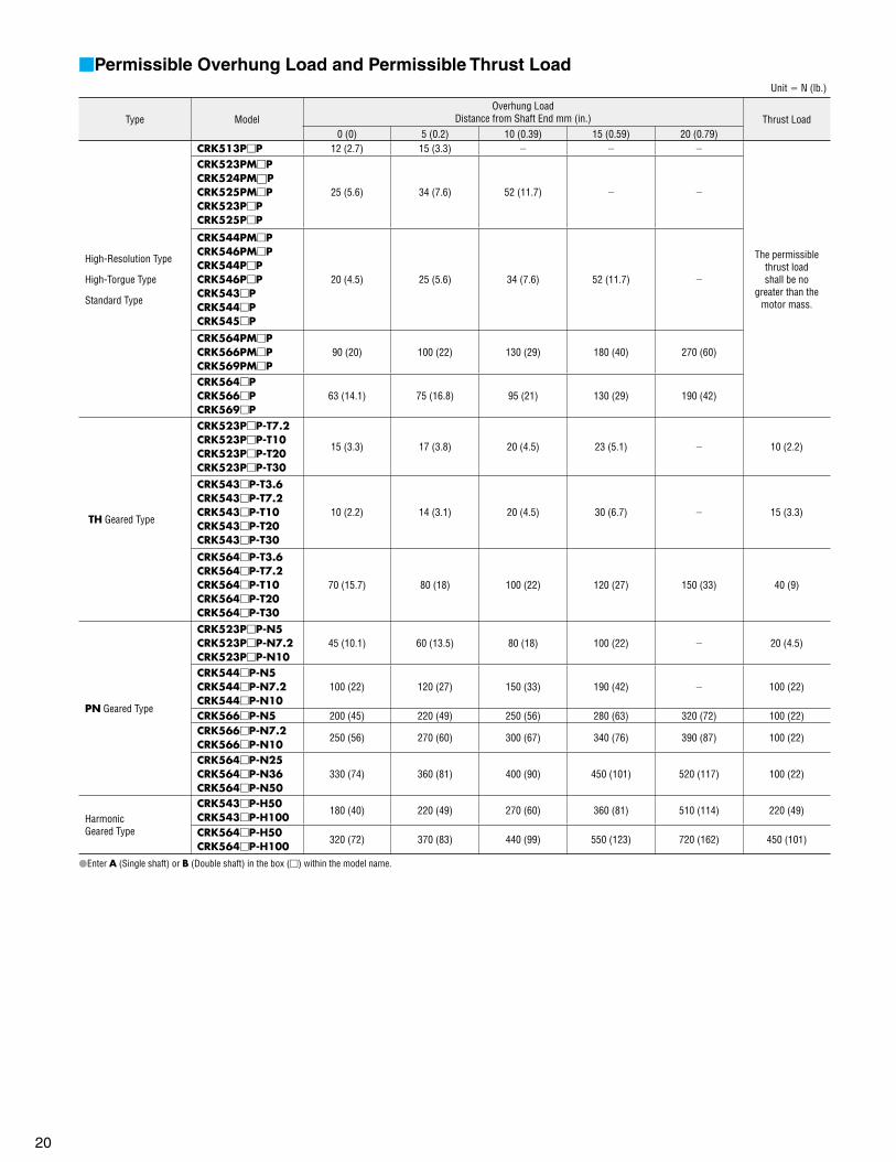
Permissible Overhung Load and Permissible Thrust Load Unit N (lb.)
Type ModelOverhung Load
Distance from Shaft End mm (in.) Thrust Load0 (0) 5 (0.2) 10 (0.39) 15 (0.59) 20 (0.79)
High-Resolution Type
High-Torgue Type
Standard Type
CRK513PP 12 (2.7) 15 (3.3)
The permissiblethrust loadshall be no
greater than themotor mass.
CRK523PMPCRK524PMPCRK525PMPCRK523PPCRK525PP
25 (5.6) 34 (7.6) 52 (11.7)
CRK544PMPCRK546PMPCRK544PPCRK546PPCRK543PCRK544PCRK545P
20 (4.5) 25 (5.6) 34 (7.6) 52 (11.7)
CRK564PMPCRK566PMPCRK569PMP
90 (20) 100 (22) 130 (29) 180 (40) 270 (60)
CRK564PCRK566PCRK569P
63 (14.1) 75 (16.8) 95 (21) 130 (29) 190 (42)
TH Geared Type
CRK523PP-T7.2CRK523PP-T10CRK523PP-T20CRK523PP-T30
15 (3.3) 17 (3.8) 20 (4.5) 23 (5.1) 10 (2.2)
CRK543P-T3.6CRK543P-T7.2CRK543P-T10CRK543P-T20CRK543P-T30
10 (2.2) 14 (3.1) 20 (4.5) 30 (6.7) 15 (3.3)
CRK564P-T3.6CRK564P-T7.2CRK564P-T10CRK564P-T20CRK564P-T30
70 (15.7) 80 (18) 100 (22) 120 (27) 150 (33) 40 (9)
PN Geared Type
CRK523PP-N5CRK523PP-N7.2CRK523PP-N10
45 (10.1) 60 (13.5) 80 (18) 100 (22) 20 (4.5)
CRK544P-N5CRK544P-N7.2CRK544P-N10
100 (22) 120 (27) 150 (33) 190 (42) 100 (22)
CRK566P-N5 200 (45) 220 (49) 250 (56) 280 (63) 320 (72) 100 (22)CRK566P-N7.2CRK566P-N10
250 (56) 270 (60) 300 (67) 340 (76) 390 (87) 100 (22)
CRK564P-N25CRK564P-N36CRK564P-N50
330 (74) 360 (81) 400 (90) 450 (101) 520 (117) 100 (22)
HarmonicGeared Type
CRK543P-H50CRK543P-H100
180 (40) 220 (49) 270 (60) 360 (81) 510 (114) 220 (49)
CRK564P-H50CRK564P-H100
320 (72) 370 (83) 440 (99) 550 (123) 720 (162) 450 (101)
Enter A (Single shaft) or B (Double shaft) in the box () within the model name.
21
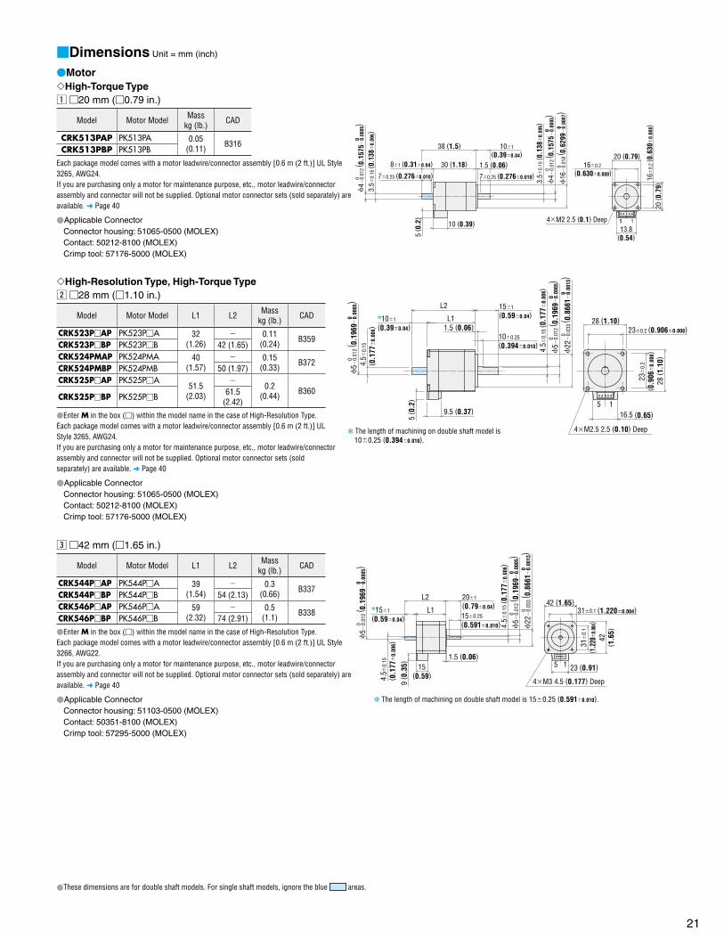
Dimensions Unit = mm (inch)
MotorHigh-Torque Typez 20 mm (0.79 in.)
Model Motor Model Masskg (lb.) CAD
CRK513PAP PK513PA 0.05(0.11) B316
CRK513PBP PK513PB
Each package model comes with a motor leadwire/connector assembly [0.6 m (2 ft.)] UL Style 3265, AWG24.If you are purchasing only a motor for maintenance purpose, etc., motor leadwire/connector assembly and connector will not be supplied. Optional motor connector sets (sold separately) are available. Page 40
Applicable Connector Connector housing: 51065-0500 (MOLEX) Contact: 50212-8100 (MOLEX) Crimp tool: 57176-5000 (MOLEX)
154M2 2.5 (0.1) Deep
20 (0.79)
13.8(0.54)
20 ( 0
.79)4
0.01
2 ( 0
.157
50.
0005
)0
0
3.5
0.15
( 0.1
38
0.00
6)
3.5
0.15
( 0.1
38
0.00
6)
70.25 (0.2760.010) 70.25 (0.2760.010)
160.2
(0.6300.008)
16
0.2
( 0.6
30
0.00
8)
81 (0.310.04)
38 (1.5)
10 (0.39)
5 ( 0
.2)
101
(0.390.04)30 (1.18) 1.5 (0.06)
4
0.01
2 ( 0
.157
50.
0005
)0
0
16
0.
018
( 0.6
299
0.00
07)
00
High-Resolution Type, High-Torque Typex 28 mm (1.10 in.)
Model Motor Model L1 L2 Masskg (lb.) CAD
CRK523PAP PK523PA 32(1.26)
0.11(0.24) B359
CRK523PBP PK523PB 42 (1.65)CRK524PMAP PK524PMA 40
(1.57) 0.15
(0.33) B372CRK524PMBP PK524PMB 50 (1.97)CRK525PAP PK525PA
51.5(2.03)
0.2
(0.44) B360CRK525PBP PK525PB 61.5
(2.42)
Enter M in the box () within the model name in the case of High-Resolution Type.Each package model comes with a motor leadwire/connector assembly [0.6 m (2 ft.)] UL Style 3265, AWG24.If you are purchasing only a motor for maintenance purpose, etc., motor leadwire/connector assembly and connector will not be supplied. Optional motor connector sets (sold separately) are available. Page 40
Applicable Connector Connector housing: 51065-0500 (MOLEX) Contact: 50212-8100 (MOLEX) Crimp tool: 57176-5000 (MOLEX)
5 116.5 (0.65)
L1
L2
230.2 (0.9060.008)
23
0.2
( 0.9
06
0.00
8)22
0.
033
( 0.8
661
0.00
13)
0
4M2.5 2.5 (0.10) Deep The length of machining on double shaft model is 100.25 (0.3940.010).
5
0.01
2 ( 0
.196
90.
0005
)0
0
4.5
0.15
( 0.1
77
0.00
6)
101
(0.390.04) 1.5 (0.06)
151
(0.590.04)
100.25
(0.3940.010) 4.5
0.15
( 0.1
77
0.00
6)
5
0.01
2 ( 0
.196
90.
0005
)0
0
0
9.5 (0.37)5
( 0.2
)
28 (1.10)
28 ( 1
.10)
c 42 mm (1.65 in.)
Model Motor Model L1 L2 Masskg (lb.) CAD
CRK544PAP PK544PA 39(1.54)
0.3(0.66) B337
CRK544PBP PK544PB 54 (2.13)CRK546PAP PK546PA 59
(2.32) 0.5
(1.1) B338CRK546PBP PK546PB 74 (2.91)
Enter M in the box () within the model name in the case of High-Resolution Type.Each package model comes with a motor leadwire/connector assembly [0.6 m (2 ft.)] UL Style 3266, AWG22.If you are purchasing only a motor for maintenance purpose, etc., motor leadwire/connector assembly and connector will not be supplied. Optional motor connector sets (sold separately) are available. Page 40
Applicable Connector Connector housing: 51103-0500 (MOLEX) Contact: 50351-8100 (MOLEX) Crimp tool: 57295-5000 (MOLEX)
1.5 (0.06)
4.5
0.15
( 0.1
77
0.00
6)
L1
L2
5 1
42 (1.65)310.1 (1.2200.004)
31
0.1
( 1.2
20
0.00
4)42
( 1.6
5)
23 (0.91)15(0.59)
9 ( 0
.35)
4M3 4.5 (0.177) Deep
The length of machining on double shaft model is 150.25 (0.5910.010).
151
(0.590.04)
4.5
0.15
( 0.1
77
0.00
6)
150.25
(0.5910.010)
201
(0.790.04)
5
0.01
2 ( 0
.196
90.
0005
)0
0
22
0.
033
( 0.8
661
0.00
13)
00
5
0.01
2 ( 0
.196
90.
0005
)0
0
These dimensions are for double shaft models. For single shaft models, ignore the blue areas.

22
Standard Typeb 42 mm (1.65 in.)
Model Motor Model L1 L2 Masskg (lb.) CAD
CRK543AP PK543NAW 33(1.30)
0.21(0.46) B068
CRK543BP PK543NBW 48 (1.89)CRK544AP PK544NAW 39
(1.54) 0.27
(0.59) B069CRK544BP PK544NBW 54 (2.13)CRK545AP PK545NAW 47
(1.85) 0.35
(0.77) B070CRK545BP PK545NBW 62 (2.44)
UL Style 3265, AWG24
4M3 4.5 (0.177) Deep5 Motor Leads 600 mm (24 inch) Length
2 (0.08)
4.5
0.15
( 0.1
77
0.00
6)
42 (1.65)310.2 (1.2200.008)
31
0.2
( 1.2
20
0.00
8)
L1
L2
150.25
(0.5910.010)
42( 1
.65)
The length of machining on double shaft model is 150.25 (0.5910.010).
5
0.01
2 ( 0
.196
90.
0005
)0
0
151
(0.590.04)
4.5
0.15
( 0.1
77
0.00
6)
201
(0.790.04)
5
0.01
2 ( 0
.196
90.
0005
)0
0
22
0.
033
( 0.8
661
0.00
13)
00
n 60 mm (2.36 in.)
Model Motor Model L1 L2 Masskg (lb.) CAD
CRK564AP PK564NAW 46.5(1.83)
0.6(1.32) B071
CRK564BP PK564NBW 69.5 (2.74)CRK566AP PK566NAW 57.5
(2.26) 0.8
(1.76) B072CRK566BP PK566NBW 80.5 (3.17)CRK569AP PK569NAW 87
(3.43) 1.3
(2.9) B073CRK569BP PK569NBW 110 (4.33)
L17(0.28) 1.5 (0.06)
231
(0.910.04)
Shaft CrossSection AA
UL Style 3266, AWG225 Motor Leads 600 mm (24 inch) Length
7.50.15
(0.2950.006)
7.5
0.15
( 0.2
95
0.00
6)
90˚
200.25
(0.7870.010) A
A
A
A
44.5 (0.177) Thru60 (2.36)
500.35
(1.9690.014)
50
0.35
( 1.9
69
0.01
4)
60( 2
.36)
200.25 (0.7870.010)
L2 241 (0.940.04)
8
0.01
5 ( 0
.315
00.
0006
)0
0
8
0.01
5 ( 0
.315
00.
0006
)0
0
36
0.
039
( 1.4
173
0.00
15)
00
These dimensions are for double shaft models. For single shaft models, ignore the blue areas.
15
L1
L3
L2
D
7(0.28) 1.5(0.06)
231
(0.910.04)
200.25
(0.7870.010)
44.5 (0.177) Thru60 (2.36)
29(1.14)
21.5(0.85)
0.5(0.02)
500.35
(1.9690.014)
50
0.35
( 1.9
69
0.01
4)60
( 2.3
6)
12 ( 0
.47)
200.25
(0.7870.010)
241
(0.940.04)
8
0.01
5 ( 0
.315
00.
0006
)0
0
36
0.
039
( 1.4
173
0.00
15)
0 0
7.5
0.15
( 0.2
95
0.00
6)
High-Resolution Typev 60 mm (2.36 in.)
Model Motor Model L1 L2 L3 D Masskg (lb.) CAD
CRK564PMAP PK564PMA46.5
(1.83)
7.50.15
(0.2950.006)
080.015
(0.3150 0
0.006)
0.65
(1.43)B373
CRK564PMBP PK564PMB69.5
(2.74)CRK566PMAP PK566PMA
56(2.20)
0.87
(1.91)B374
CRK566PMBP PK566PMB79
(3.11)
CRK569PMAP PK569PMA87
(3.43)
9.50.15
(0.3740.006)
0100.015
(0.3937 0
0.006)
1.5
(3.3)B375
CRK569PMBP PK569PMB110
(4.33)
Each package model comes with a motor leadwire/connector assembly [0.6 m (2 ft.)] UL Style 3266, AWG22.If you are purchasing only a motor for maintenance purpose, etc., motor leadwire/connector assembly and connector will not be supplied. Optional motor connector sets (sold separately) are available. Page 40
Applicable Connector Connector housing: 51144-0500 (MOLEX) Contact: 50539-8100 (MOLEX) Crimp tool: 57189-5000 (MOLEX)
23
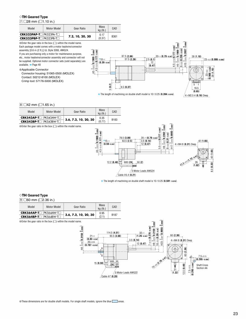
TH Geared Typem 28 mm (1.10 in.)
Model Motor Model Gear Ratio Masskg (lb.) CAD
CRK523PAP-T PK523PA-T7.2, 10, 20, 30 0.17
(0.37) B361CRK523PBP-T PK523PB-T
Enter the gear ratio in the box () within the model name.Each package model comes with a motor leadwire/connector assembly [0.6 m (2 ft.)] UL Style 3265, AWG24.If you are purchasing only a motor for maintenance purpose, etc., motor leadwire/connector assembly and connector will not be supplied. Optional motor connector sets (sold separately) are available. Page 40
Applicable Connector Connector housing: 51065-0500 (MOLEX) Contact: 50212-8100 (MOLEX) Crimp tool: 57176-5000 (MOLEX)
57.5 (2.26)67.5 (2.66)
2.5 (0.1)12
(0.47)
4M2.5 4 (0.16) Deep
101
(0.390.04)
201 (0.790.04)
5 116.5
(0.65)
60.
5 ( 0
.236
0.
020)
The length of machining on double shaft model is 100.25 (0.3940.010).
50.
012
( 0.1
969
0.00
05)
00
4.5
0.15
( 0.1
77
0.00
6)
9.5 (0.37)
5 ( 0
.2)
23
0.2
( 0.9
06
0.00
8)28
( 1.1
0)
230.2 (0.9060.008)28 (1.10)
4.5
0.15
( 0.1
77
0.00
6)
50.
012
( 0.1
969
0.00
05)
00
10
0.
015
( 0.3
937
0.00
06)
00
, 42 mm (1.65 in.)
Model Motor Model Gear Ratio Masskg (lb.) CAD
CRK543AP-T PK543AW-T3.6, 7.2, 10, 20, 30 0.35
(0.77) B183CRK543BP-T PK543BW-T
Enter the gear ratio in the box () within the model name.
12 (0.47)3.5 (0.14)63.5 (2.5)
50 (2)12.2 (0.48)
201 (0.790.04)
600 (24)
8.5
( 0.3
3)42
( 1.6
5)
42 (1.65)
43.80.5 (1.720.02)
26(1.02)
78.5 (3.09)
Cable 5.4 (0.21)5 Motor Leads AWG24
4M4 8 (0.31) Deep
The length of machining on double shaft model is 150.25 (0.5910.010).
5
0.01
2 ( 0
.196
90.
0005
)0
0
4.5
0.15
( 0.1
77
0.00
6)
151
(0.590.04)
80.
5 ( 0
.31
0.02
)
5.5
0.15
( 0.2
17
0.00
6)
6
0.01
2 ( 0
.236
20.
0005
)0
0
17
0.
018
( 0.6
693
0.00
07)
00
TH Geared Type. 60 mm (2.36 in.)
Model Motor Model Gear Ratio Masskg (lb.) CAD
CRK564AP-T PK564AW-T3.6, 7.2, 10, 20, 30 0.95
(2.1) B187CRK564BP-T PK564BW-T
Enter the gear ratio in the box () within the model name.
A
A
4M4 8 (0.31) Deep
50(2)15 (0.59)
93.5 (3.68)114.5 (4.51)
12.5
( 0.4
9)60
( 2.3
6)
200.25
(0.7870.010)
600(24)
321
(1.260.04)
3.5 (0.14)
10
0.5
( 0.3
90.
02)
12 (0.47)
60 (2.36)
31(1.22)
700.5 (2.760.02)
Cable 7 (0.28)5 Motor Leads AWG22
Shaft CrossSection AA
7.50.15
(0.2950.006)
7.5
0.15
( 0.2
95
0.00
6)
90˚
8
0.01
5 ( 0
.315
00.
0006
)0
0
211
(0.830.04)
70.
15 ( 0
.276
0.
006)
8
0.01
5 ( 0
.315
00.
0006
)0
0
23
0.
021
( 0.9
055
0.00
08)
00
These dimensions are for double shaft models. For single shaft models, ignore the blue areas.

24
PN Geared Type⁄0 28 mm (1.10 in.)
Model Motor Model Gear Ratio Masskg (lb.) CAD
CRK523PAP-N PK523PA-N5, 7.2, 10 0.25
(0.55) B362CRK523PBP-N PK523PB-N
Enter the gear ratio in the box () within the model name.Each package model comes with a motor leadwire/connector assembly [0.6 m (2 ft.)] UL Style 3265, AWG24.If you are purchasing only a motor for maintenance purpose, etc., motor leadwire/connector assembly and connector will not be supplied. Optional motor connector sets (sold separately) are available. Page 40
Applicable Connector Connector housing: 51065-0500 (MOLEX) Contact: 50212-8100 (MOLEX) Crimp tool: 57176-5000 (MOLEX)
These dimensions are for double shaft models. For single shaft models, ignore the blue areas.
⁄1 42 mm (1.65 in.)
Model Motor Model Gear Ratio Masskg (lb.) CAD
CRK544AP-N PK544AW-N5, 7.2, 10 0.56
(1.23) B312CRK544BP-N PK544BW-N
Enter the gear ratio in the box () within the model name.
Shaft CrossSection AA
A
A Parallel Key (Included)
8.5
( 0.3
3)42
( 1.6
5)
26(1.02)
4M4 8 (0.31) Deep
18 (0.71)
6 (0.24)
600(24)
50(2)12.2 (0.48)
5 Motor Leads AWG24Cable 5.4 (0.21)
86 (3.39)
71 (2.8)251 (0.980.04)
42(1.65)
480.3 (1.8900.012)
30.025 0
30.
025
0
180.2
(0.7090.008)4.5
0.15
( 0.1
77
0.00
6)
The length of machining on double shaft model is 150.25 (0.5910.010).
5
0.01
2 ( 0
.196
90.
0005
)0
0
151
(0.590.04)
10
0.
015
( 0.3
937
0.00
06)
0
0
37.6
0.
025
( 1.4
803
0.00
10)
0
30.029 0.004
(0.1181 0.0011)0.0002
(0.1181 0.0010) 0( 0.1
181
0.
0010
)
0
1.8
0
0.1
( 0.0
71 0
)
0.00
4
0
⁄2 60 mm (2.36 in.)
Model Motor Model Gear Ratio L1 L2 Masskg (lb.) CAD
CRK566AP-N PK566AW-N5, 7.2, 10 103.5
(4.07) 1.5
(3.3) B190CRK566BP-N PK566BW-N 124.5 (4.90)CRK564AP-N PK564AW-N
25, 36, 50 108.5(4.27)
1.5(3.3) B191
CRK564BP-N PK564BW-N 129.5 (5.10)
Enter the gear ratio in the box () within the model name.
50(2)15
(0.59)
12.5
( 0.4
9) 6
0 ( 2
.36)
600(24)
L1381
(1.500.04) 60 (2.36)
31(1.22)
6 (0.24)
25 (0.98)
700.5 (2.760.02)
200.25
(0.7870.010)
211
(0.830.04)
L2
Cable 7 (0.28)5 Motor Leads AWG22
B A
B A
4M5 10 (0.39) Deep
Parallel Key (Included)
040.03
0250.21 0
40.
03
7.50.15
(0.2950.006)
7.5
0.15
( 0.2
95
0.00
6)
90˚
Shaft CrossSection BB
Shaft CrossSection AA
040.03
0.
12.
5 0
8
0.01
5 ( 0
.315
00.
0006
)0
0
12
0.
018
( 0.4
724
0.00
07)
00
37
0.
025
( 1.4
567
0.00
10)
00
(0.9843 0.0083) 0
(0.1575 0.0012) 0
(0.1575 0.0012) 0( 0.1
575
0.
0012
)
0
( 0.0
98 0
)
0.00
4
A
A
5 1
Shaft CrossSection AA
16.5(0.65)
62.5 (2.46)
72.5 (2.85)
5 (0.2)
15(0.60)
17(0.67)
90˚
28 (1.10)
231
(0.910.04)
230.2 (0.9060.008)
12
( 0.4
7)
5 ( 0
.2)
9.5(0.37)
7.50.2
(0.2950.008)
7.5
0.2
( 0.2
95
0.00
8)
28 ( 1
.10)
23
0.2
( 0.9
06
0.00
8)
4M3 6 (0.24) Deep
The length of machining on double shaft model is 100.25 (0.3940.010).
50.
012
( 0.1
969
0.00
05)
00 4.
50.
15
( 0.1
77
0.00
6)
101
(0.390.04)
8
0.01
5 ( 0
.315
00.
0006
)0
0
26
0.
021
( 1.0
236
0.00
08)
00
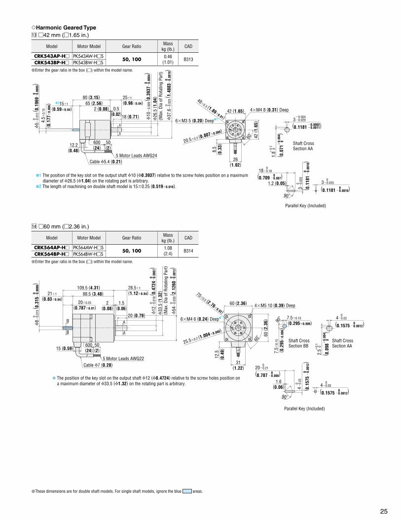
25
Harmonic Geared Type⁄3 42 mm (1.65 in.)
Model Motor Model Gear Ratio Masskg (lb.) CAD
CRK543AP-H PK543AW-HS50, 100 0.46
(1.01) B313CRK543BP-H PK543BW-HS
Enter the gear ratio in the box () within the model name.
A
A
26(1.02)
80 (3.15)
50(2)12.2
(0.48)
600(24)
65 (2.56)2 (0.08) 0.5
(0.02)18 (0.71)
1.2 (0.05)
251
(0.980.04)
26
.5 ( 1
.04)
(Max
. Dia
of R
otat
ing
Part)
5 Motor Leads AWG24Cable 5.4 (0.21)
6M3 5 (0.20) Deep1
42 (1.65) 4M4 8 (0.31) Deep
60˚
8.5
( 0.3
3)
42 ( 1
.65)
480.3 (1.890.01)
20.50.2 (0.8070.008)
30.025 0
30.
025
0
30.029 0.004
1.8
0
0.1
90˚
Shaft CrossSection AA
Parallel Key (Included)
180.180
1 The position of the key slot on the output shaft 10 (0.3937) relative to the screw holes position on a maximum diameter of 26.5 (1.04) on the rotating part is arbitrary.2 The length of machining on double shaft model is 150.25 (0.5190.010).
5
0.01
2 ( 0
.196
90.
0005
)0
0 4.5
0.15
( 0.1
77
0.00
6) 2151
(0.590.04)
10
0.
009
( 0.3
937
0.00
04)
0
0
37.6
0.
025
( 1.4
803
0.00
10)
0
(0.1181 0.0011)0.0002
( 0.0
71
0
)
0.
004
(0.1181 0.0010) 0( 0.1
181
0.
0010
) 0
(0.709 0.007)0
These dimensions are for double shaft models. For single shaft models, ignore the blue areas.
⁄4 60 mm (2.36 in.)
Model Motor Model Gear Ratio Masskg (lb.) CAD
CRK564AP-H PK564AW-HS50, 100 1.08
(2.4) B314CRK564BP-H PK564BW-HS
Enter the gear ratio in the box () within the model name.
B
B A
A
31(1.22)
6M4 6 (0.24) Deep
12.5
( 0.4
9)
60 ( 2
.36)
50(2)15 (0.59)
600(24)
88.5 (3.48)
20 (0.79)
109.5 (4.31)
2(0.08)
1.5(0.06)
211
(0.830.04)
28.51
(1.120.04)
200.25
(0.7870.01)
5 Motor Leads AWG22Cable 7 (0.28)
33
.5 ( 1
.32)
( Max
. Dia
of R
otat
ing
Part)
60 (2.36)
700.5 (2.760.02)
25.50.2 (1.0040.008)
60˚
4M5 10 (0.39) Deep
Shaft CrossSection AA
Shaft CrossSection BB
1.6(0.06) 40.03
0
40.03 0
200.21 0
2.5
0
0.1
40.
03 0
Parallel Key (Included)
7.50.15
(0.2950.006)
7.5
0.15
( 0.2
95
0.00
6)90
90˚
The position of the key slot on the output shaft 12 (0.4724) relative to the screw holes position on a maximum diameter of 33.5 (1.32) on the rotating part is arbitrary.
8
0.01
5 ( 0
.315
0.
0006
)0
0
12
0.
018
( 0.4
724
0.00
07)
00
54
0.
030
( 2.1
260
0.00
12)
00
( 0.0
98 0
)
0.00
4(0.1575 0.0012) 0
(0.1575 0.0012) 0( 0.1
575
0.
0012
) 0(0.787 0.008)0

26
Driver⁄5 Driver Model: CRD5103P, CRD5107P, CRD5114PMass: 0.04 kg (0.088 lb.) B363
C
0
4
8
C
0
4
8
45 ( 1
.77)
31( 1
.22)
14.9
( 0.5
9)
32.4 (1.28)
7.4
( 0.2
9)
65 (2.56)
11.5
( 0.4
5)
24.3
( 0.9
6)
41.4 (1.63)
21.9
( 0.8
6)
3(0.12)
59 (2.32) 3( 0
.12)
43.5 (0.138 DIA) Thru
25 m
ax.
( 0.9
8 m
ax.)
4 m
ax.
( 0.1
6 m
ax.)
AccessoriesConnector Housing (Included) 51103-0200 (MOLEX) 51103-1200 (MOLEX) 51103-0500 (MOLEX)
Contact (Included) 50351-8100 (MOLEX)
Notes:Be sure to use the included connector for signal and motor and power supply. When assembling the connectors, use the hand-operated crimp tool [57295-5000 (MOLEX)].
The crimp tool is not provided with the package. It must be furnished separately.Driver leadwire set crimped with connector (sold separately) are available.
Driver leadwire set Page 40
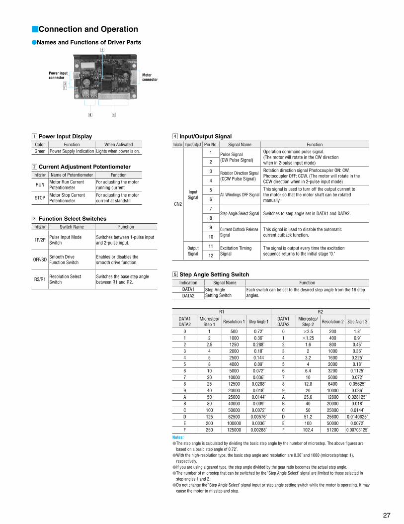
27
Connection and Operation
Names and Functions of Driver Parts
Power inputconnector
Motorconnector
b
x
cz
v
z Power Input DisplayColor Function When ActivatedGreen Power Supply Indication Lights when power is on.
x Current Adjustment PotentiometerIndication Name of Potentiometer Function
RUN Motor Run CurrentPotentiometer
For adjusting the motorrunning current
STOP Motor Stop CurrentPotentiometer
For adjusting the motor current at standstill
c Function Select SwitchesIndication Switch Name Function
1P/2P Pulse Input Mode Switch
Switches between 1-pulse input and 2-pulse input.
OFF/SD Smooth DriveFunction Switch
Enables or disables thesmooth drive function.
R2/R1 Resolution Select Switch
Switches the base step anglebetween R1 and R2.
v Input/Output SignalIndication Input/Output Pin No. Signal Name Function
CN2
Input Signal
1 Pulse Signal(CW Pulse Signal)
Operation command pulse signal.(The motor will rotate in the CW directionwhen in 2-pulse input mode) 2
3 Rotation Direction Signal(CCW Pulse Signal)
Rotation direction signal Photocoupler ON: CW, Photocoupler OFF: CCW. (The motor will rotate in the CCW direction when in 2-pulse input mode)4
5All Windings OFF Signal
This signal is used to turn off the output current tothe motor so that the motor shaft can be rotatedmanually.6
7Step Angle Select Signal Switches to step angle set in DATA1 and DATA2.
8
9 Current Cutback ReleaseSignal
This signal is used to disable the automaticcurrent cutback function.10
Output Signal
11 Excitation TimingSignal
The signal is output every time the excitationsequence returns to the initial stage "0."12
b Step Angle Setting SwitchIndication Signal Name Function
DATA1 Step AngleSetting Switch
Each switch can be set to the desired step angle from the 16 step angles.DATA2
R1 R2DATA1DATA2
Microstep/Step 1 Resolution 1 Step Angle 1 DATA1
DATA2Microstep/
Step 2 Resolution 2 Step Angle 2
0 1 500 0.72˚ 0 2.5 200 1.8˚1 2 1000 0.36˚ 1 1.25 400 0.9˚2 2.5 1250 0.288˚ 2 1.6 800 0.45˚3 4 2000 0.18˚ 3 2 1000 0.36˚4 5 2500 0.144 4 3.2 1600 0.225˚5 8 4000 0.09˚ 5 4 2000 0.18˚6 10 5000 0.072˚ 6 6.4 3200 0.1125˚7 20 10000 0.036˚ 7 10 5000 0.072˚8 25 12500 0.0288˚ 8 12.8 6400 0.05625˚9 40 20000 0.018˚ 9 20 10000 0.036˚A 50 25000 0.0144˚ A 25.6 12800 0.028125˚B 80 40000 0.009˚ B 40 20000 0.018˚C 100 50000 0.0072˚ C 50 25000 0.0144˚D 125 62500 0.00576˚ D 51.2 25600 0.0140625˚E 200 100000 0.0036˚ E 100 50000 0.0072˚F 250 125000 0.00288˚ F 102.4 51200 0.00703125˚
Notes: The step angle is calculated by dividing the basic step angle by the number of microstep. The above figures are
based on a basic step angle of 0.72˚. With the high-resolution type, the basic step angle and resolution are 0.36˚ and 1000 (microstep/step: 1),
respectively. If you are using a geared type, the step angle divided by the gear ratio becomes the actual step angle. The number of microstep that can be switched by the "Step Angle Select" signal are limited to those selected in
step angles 1 and 2. Do not change the "Step Angle Select" signal input or step angle setting switch while the motor is operating. It may
cause the motor to misstep and stop.
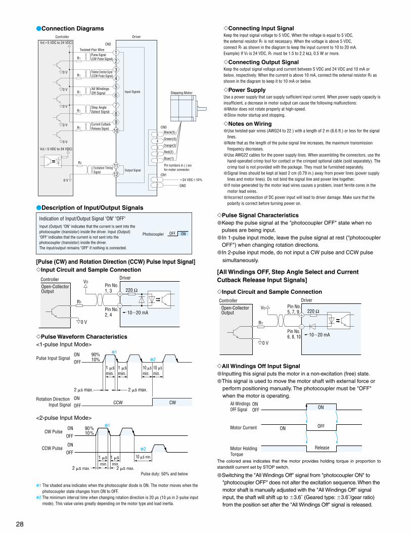
28
Connection Diagrams
Stepping Motor
CN2
Black(5)
Green(4)
Orange(3)
Red(2)
Blue(1)
CN3
CN1
GND
Twisted-Pair WirePulse Signal (CW Pulse Signal)
Rotation Direction Signal (CCW Pulse Signal)
Excitation Timing Signal Output Signal
All Windings Off Signal
Step Angle Select Signal
Current Cutback Release Signal
DriverController
0 V
0 V
2
1
4
3
6
5
8
7
10
9
Pin numbers in ( ) arefor motor connector.
11
21
1
2
3
4
5
0 V
0 V
0 V
0 V
Input Signals
12
V0(5 VDC to 24 VDC)
V0(5 VDC to 24 VDC)
R1
24 VDC10%
R1
R1
R1
R2
R1
Description of Input/Output Signals
Photocoupler OFF ON
Indication of Input/Output Signal "ON" "OFF"Input (Output) "ON" indicates that the current is sent into the photocoupler (transistor) inside the driver. Input (Output) "OFF" indicates that the current is not sent into the photocoupler (transistor) inside the driver. The input/output remains "OFF" if nothing is connected.
[Pulse (CW) and Rotation Direction (CCW) Pulse Input Signal]Input Circuit and Sample Connection
Controller Driver
Pin No.1, 3
Pin No.2, 4
VO
R1
0 V
1020 mA
220 ΩOpen-Collector Output
Pulse Waveform Characteristics<1-pulse Input Mode>
90%10%
CCW CWON
OFF
ON
OFFPulse Input Signal
Rotation Direction Input Signal
2 s max. 2 s max.
1 smin.
1 smin.
10 smin.
10 smin.
1
2
<2-pulse Input Mode>
ON
OFF
ON
OFF
1
2
90%10%CW Pulse
CCW Pulse
2 s max. 2 s max.
10 s min.1 smin.
1 smin.
Pulse duty: 50% and below
1 The shaded area indicates when the photocoupler diode is ON. The motor moves when the photocoupler state changes from ON to OFF.
2 The minimum interval time when changing rotation direction is 20 µs (10 µs in 2-pulse input mode). This value varies greatly depending on the motor type and load inertia.
Pulse Signal Characteristics Keep the pulse signal at the "photocoupler OFF" state when no
pulses are being input. In 1-pulse input mode, leave the pulse signal at rest ("photocoupler
OFF") when changing rotation directions. In 2-pulse input mode, do not input a CW pulse and CCW pulse
simultaneously.
[All Windings OFF, Step Angle Select and Current Cutback Release Input Signals]
Input Circuit and Sample Connection
Controller DriverPin No.5, 7, 9
Pin No.6, 8, 10
220 Ω
1020 mA
VO
R1
0 V
Open-Collector Output
All Windings Off Input Signal Inputting this signal puts the motor in a non-excitation (free) state. This signal is used to move the motor shaft with external force or
perform positioning manually. The photocoupler must be "OFF" when the motor is operating.
ONOFF
All Windings OFF Signal ON
OFFONMotor Current
Motor Holding Torque
Release
The colored area indicates that the motor provides holding torque in proportion to standstill current set by STOP switch.
Switching the "All Windings Off" signal from "photocoupler ON" to "photocoupler OFF" does not alter the excitation sequence. When the motor shaft is manually adjusted with the "All Windings Off" signal input, the shaft will shift up to 3.6˚ (Geared type: 3.6˚/gear ratio) from the position set after the "All Windings Off" signal is released.
Connecting Input SignalKeep the input signal voltage to 5 VDC. When the voltage is equal to 5 VDC, the external resistor R1 is not necessary. When the voltage is above 5 VDC, connect R1 as shown in the diagram to keep the input current to 10 to 20 mA.Example) If V0 is 24 VDC, R1 must be 1.5 to 2.2 kΩ, 0.5 W or more.
Connecting Output SignalKeep the output signal voltage and current between 5 VDC and 24 VDC and 10 mA or below, respectively. When the current is above 10 mA, connect the external resistor R2 as shown in the diagram to keep it to 10 mA or below.
Power SupplyUse a power supply that can supply sufficient input current. When power supply capacity is insufficient, a decrease in motor output can cause the following malfunctions:Motor does not rotate properly at high-speed.Slow motor startup and stopping.
Notes on WiringUse twisted-pair wires (AWG24 to 22 ) with a length of 2 m (6.6 ft.) or less for the signal
lines.Note that as the length of the pulse signal line increases, the maximum transmission
frequency decreases.Use AWG22 cables for the power supply lines. When assembling the connectors, use the
hand-operated crimp tool for contact or the crimped optional cable (sold separately). The crimp tool is not provided with the package. They must be furnished separately.
Signal lines should be kept at least 2 cm (0.79 in.) away from power lines (power supply lines and motor lines). Do not bind the signal line and power line together.
If noise generated by the motor lead wires causes a problem, insert ferrite cores in the motor lead wires.
Incorrect connection of DC power input will lead to driver damage. Make sure that the polarity is correct before turning power on.
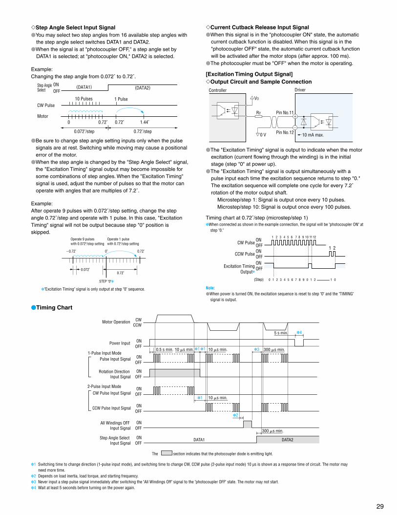
29
Step Angle Select Input Signal You may select two step angles from 16 available step angles with
the step angle select switches DATA1 and DATA2. When the signal is at "photocoupler OFF," a step angle set by
DATA1 is selected; at "photocoupler ON," DATA2 is selected.
Example:Changing the step angle from 0.072˚ to 0.72˚.
Step AngleSelect
CW Pulse
Motor
ONOFF
(DATA1) (DATA2)
10 Pulses 1 Pulse
0 0.72˚ 1.44˚0.72˚
0.072˚/step 0.72˚/step
Be sure to change step angle setting inputs only when the pulse signals are at rest. Switching while moving may cause a positional error of the motor.
When the step angle is changed by the "Step Angle Select" signal, the "Excitation Timing" signal output may become impossible for some combinations of step angles. When the "Excitation Timing" signal is used, adjust the number of pulses so that the motor can operate with angles that are multiples of 7.2˚.
Example:After operate 9 pulses with 0.072˚/step setting, change the step angle 0.72˚/step and operate with 1 pulse. In this case, "Excitation Timing" signal will not be output because step "0" position is skipped.
0˚
0.72˚
0.72˚ 0.72˚
0.072˚
Operate 9 pulses with 0.072/step setting
Operate 1 pulsewith 0.72/step setting
STEP "0"
"Excitation Timing" signal is only output at step "0" sequence.
Current Cutback Release Input Signal When this signal is in the "photocoupler ON" state, the automatic
current cutback function is disabled. When this signal is in the "photocoupler OFF" state, the automatic current cutback function will be activated after the motor stops (after approx. 100 ms).
The photocoupler must be "OFF" when the motor is operating.
[Excitation Timing Output Signal]Output Circuit and Sample Connection
Controller Driver
Pin No.12
Pin No.11
VO
R2
0 V
10 mA max.
The "Excitation Timing" signal is output to indicate when the motor excitation (current flowing through the winding) is in the initial stage (step "0" at power up).
The "Excitation Timing" signal is output simultaneously with a pulse input each time the excitation sequence returns to step "0." The excitation sequence will complete one cycle for every 7.2˚rotation of the motor output shaft.
Microstep/step 1: Signal is output once every 10 pulses. Microstep/step 10: Signal is output once every 100 pulses.
Timing chart at 0.72˚/step (microstep/step 1) When connected as shown in the example connection, the signal will be "photocoupler ON" at
step "0."
CW Pulse
CCW Pulse
Excitation TimingOutput
1 2 3 4 5 6 7 8 9 10 11 12
1 2
(Step) 0 1 2 3 4 5 6 7 8 9 0 1 2 1 0
ONOFFONOFFONOFF
Note:When power is turned ON, the excitation sequence is reset to step "0" and the "TIMING"
signal is output.
Timing Chart
DATA2
The section indicates that the photocoupler diode is emitting light.
DATA1
Motor Operation
Power Input
2-Pulse Input Mode
1-Pulse Input Mode
Rotation Direction Input Signal
Pulse Input Signal
CW Pulse Input Signal
CCW Pulse Input Signal
All Windings OFF Input Signal
Step Angle Select Input Signal
ONOFF
ONOFF
ONOFF
ONOFF
ONOFF
ONOFF
ONOFF
CWCCW
0.5 s min. 10 s min. 10 s min.
10 s min.
1 1
1
2
3
45 s min.
300 s min.
300 s min.
1 Switching time to change direction (1-pulse input mode), and switching time to change CW, CCW pulse (2-pulse input mode) 10 µs is shown as a response time of circuit. The motor may need more time.
2 Depends on load inertia, load torque, and starting frequency.3 Never input a step pulse signal immediately after switching the "All Windings Off" signal to the "photocoupler OFF" state. The motor may not start.4 Wait at least 5 seconds before turning on the power again.
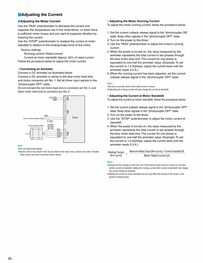
30
Adjusting the Current
Adjusting the Motor Current
Use the "RUN" potentiometer to decrease the current and suppress the temperature rise in the motor/driver, or when there is sufficient motor torque and you want to suppress vibration by lowering the current.Use the "STOP" potentiometer to readjust the current at motor standstill in relation to the holding-brake force of the motor.
Factory settings Running current: Rated current Current at motor standstill: Approx. 50% of rated currentFollow the procedure below to adjust the motor current.
Connecting an AmmeterConnect a DC ammeter as illustrated below. Connect a DC ammeter in series to the blue motor lead wire and motor connector pin No. 1. Set all driver input signals to the "photocoupler OFF" state.Do not connect the red motor lead wire to connector pin No. 2, and black motor lead wire to connector pin No. 5.
2
1
CN1
CN2
24 VDCGND
12
11 1
0 9
8
7 6
5
4
3 2
1
CN3
Current Cutback Release SignalSW
5 VDC
Driver
5
4 3
2
1
5-Phase Stepping Motor
BlueRed
OrangeGreenBlack
Note:Do not input pulse signals.Electric shock may result if the red and black motor lead wires contact each other. Insulate
these motor lead wires to prevent electric shock.
Adjusting the Motor Running CurrentTo adjust the motor running current, follow the procedure below:
1. Set the current cutback release signal to the "photocoupler ON" state. Keep other signals in the "photocoupler OFF" state.
2. Turn on the power to the driver.3. Use the "RUN" potentiometer to adjust the motor's running
current.4. When the power is turned on, the value measured by the
ammeter represents the total current in two phases through the blue motor lead wire. The current for one phase is equivalent to one-half the ammeter value. (Example: To set the current to 1.0 A/phase, adjust the current level until the ammeter reads 2.0 A.)
5. When the running current has been adjusted, set the current cutback release signal to the "photocoupler OFF" state.
Notes:Be sure to use the motor at the rated current or below.Adjusting the running current will also change the current at standstill.
Adjusting the Current at Motor StandstillTo adjust the current at motor standstill, follow the procedure below:
1. Set the current cutback release signal to the "photocoupler OFF" state. Keep other signals in the "photocoupler OFF" state.
2. Turn on the power to the driver.3. Use the "STOP" potentiometer to adjust the motor current at
standstill.4. When the power is turned on, the value measured by the
ammeter represents the total current in two phases through the blue motor lead wire. The current for one phase is equivalent to one-half the ammeter value. (Example: To set the current to 1.0 A/phase, adjust the current level until the ammeter reads 2.0 A.)
Holding Torque[Nm (oz-in)]
Maximum Holding Torque [Nm (oz-in)]Current at Standstill [A]
Motor Rated Current [A]
Notes: Always set the running current first, turn off the driver power and turn it back on, and then
set the current at standstill. Setting the running current after current at standstill may change the current setting at standstill.
Setting the current at motor standstill too low may affect the starting of the motor or the position-holding action.
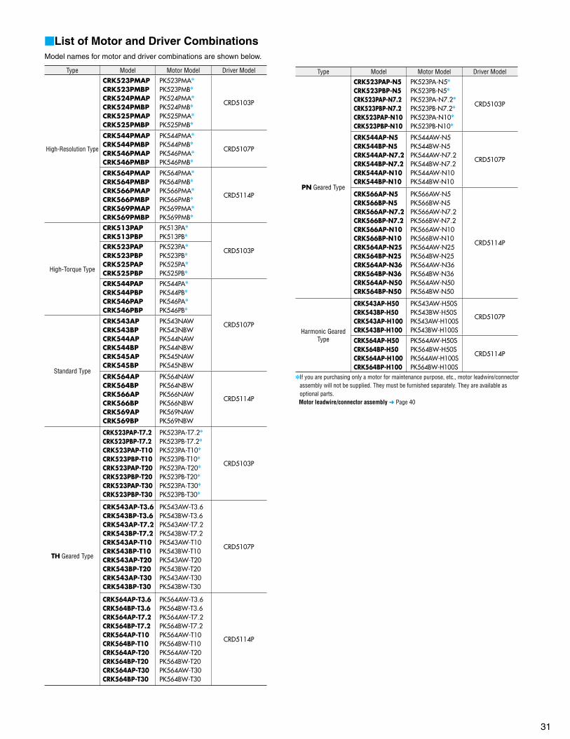
31
List of Motor and Driver CombinationsModel names for motor and driver combinations are shown below.
Type Model Motor Model Driver Model
High-Resolution Type
CRK523PMAPCRK523PMBPCRK524PMAPCRK524PMBPCRK525PMAPCRK525PMBP
PK523PMA
PK523PMB
PK524PMA
PK524PMB
PK525PMA
PK525PMB
CRD5103P
CRK544PMAPCRK544PMBPCRK546PMAPCRK546PMBP
PK544PMA
PK544PMB
PK546PMA
PK546PMB
CRD5107P
CRK564PMAPCRK564PMBPCRK566PMAPCRK566PMBPCRK569PMAPCRK569PMBP
PK564PMA
PK564PMB
PK566PMA
PK566PMB
PK569PMA
PK569PMB
CRD5114P
High-Torque Type
CRK513PAPCRK513PBP
PK513PA
PK513PB
CRD5103PCRK523PAPCRK523PBPCRK525PAPCRK525PBP
PK523PA
PK523PB
PK525PA
PK525PB
CRK544PAPCRK544PBPCRK546PAPCRK546PBP
PK544PA
PK544PB
PK546PA
PK546PB
CRD5107P
Standard Type
CRK543APCRK543BPCRK544APCRK544BP CRK545APCRK545BP
PK543NAWPK543NBWPK544NAWPK544NBWPK545NAWPK545NBW
CRK564APCRK564BPCRK566APCRK566BPCRK569APCRK569BP
PK564NAWPK564NBWPK566NAWPK566NBWPK569NAWPK569NBW
CRD5114P
TH Geared Type
CRK523PAP-T7.2CRK523PBP-T7.2CRK523PAP-T10CRK523PBP-T10CRK523PAP-T20CRK523PBP-T20CRK523PAP-T30CRK523PBP-T30
PK523PA-T7.2
PK523PB-T7.2
PK523PA-T10
PK523PB-T10
PK523PA-T20
PK523PB-T20
PK523PA-T30
PK523PB-T30
CRD5103P
CRK543AP-T3.6CRK543BP-T3.6CRK543AP-T7.2CRK543BP-T7.2CRK543AP-T10CRK543BP-T10CRK543AP-T20CRK543BP-T20CRK543AP-T30CRK543BP-T30
PK543AW-T3.6PK543BW-T3.6PK543AW-T7.2PK543BW-T7.2PK543AW-T10PK543BW-T10PK543AW-T20PK543BW-T20PK543AW-T30PK543BW-T30
CRD5107P
CRK564AP-T3.6CRK564BP-T3.6CRK564AP-T7.2CRK564BP-T7.2CRK564AP-T10CRK564BP-T10CRK564AP-T20CRK564BP-T20CRK564AP-T30CRK564BP-T30
PK564AW-T3.6PK564BW-T3.6PK564AW-T7.2PK564BW-T7.2PK564AW-T10PK564BW-T10PK564AW-T20PK564BW-T20PK564AW-T30PK564BW-T30
CRD5114P
Type Model Motor Model Driver Model
PN Geared Type
CRK523PAP-N5CRK523PBP-N5CRK523PAP-N7.2CRK523PBP-N7.2CRK523PAP-N10CRK523PBP-N10
PK523PA-N5
PK523PB-N5
PK523PA-N7.2
PK523PB-N7.2
PK523PA-N10
PK523PB-N10
CRD5103P
CRK544AP-N5CRK544BP-N5CRK544AP-N7.2CRK544BP-N7.2CRK544AP-N10CRK544BP-N10
PK544AW-N5PK544BW-N5PK544AW-N7.2PK544BW-N7.2PK544AW-N10PK544BW-N10
CRD5107P
CRK566AP-N5CRK566BP-N5CRK566AP-N7.2CRK566BP-N7.2CRK566AP-N10CRK566BP-N10CRK564AP-N25CRK564BP-N25CRK564AP-N36CRK564BP-N36CRK564AP-N50CRK564BP-N50
PK566AW-N5PK566BW-N5PK566AW-N7.2PK566BW-N7.2PK566AW-N10PK566BW-N10PK564AW-N25PK564BW-N25PK564AW-N36PK564BW-N36PK564AW-N50PK564BW-N50
CRD5114P
Harmonic GearedType
CRK543AP-H50CRK543BP-H50CRK543AP-H100CRK543BP-H100
PK543AW-H50SPK543BW-H50SPK543AW-H100SPK543BW-H100S
CRD5107P
CRK564AP-H50CRK564BP-H50CRK564AP-H100CRK564BP-H100
PK564AW-H50SPK564BW-H50SPK564AW-H100SPK564BW-H100S
CRD5114P
If you are purchasing only a motor for maintenance purpose, etc., motor leadwire/connector assembly will not be supplied. They must be furnished separately. They are available as optional parts.
Motor leadwire/connector assembly Page 40

32
Controllers
Controller for Stepping Motor
SG8030JFeaturesAll operations including data setting can easily be performed using the four touch-screen buttons on the top panel. In addition, the number of signal lines is reduced to a minimum for easy connection.
Jerk limit control function to suppress vibration during motor operationSupporting step sequential positioning operation and external signal operationMaximum oscillation frequency: 200 kHz1-pulse/2-pulse output mode switching
Stored Program Controller
EMP400 SeriesFeatures
Sample Program
In addition to the superior oscillation function refl ecting Oriental Motor's wealth of expertise in motor design and manufacturing, the EMP400 Series also provides the I/O control function and the sequence function that allows for programming of a series of operations.
32 different sequence programs can be input. Various operation patterns Teaching function
When the optional operator interface unit OP300 is used, you can adjust the travel via teaching or monitor the current position.
No special software is necessary.
0 pulse 11000 pulses
Product LineType Model
DIN Rail Mounting Model SG8030J-DRecessed Mounting Model SG8030J-U
Product LineType Number of Axes Connector
EMP401-1Single axis
Without connectorsEMP401-2 With connectorsEMP402-1
Dual axisWithout connectors
EMP402-2 With connectors
Operator Interface Unit OP300
Step No.1 Step No.3StepNo.2
Step No.4
<Sequential Positioning>
Operator Interface Unit(Sold separately)
DIN Rail Mounting Model Recessed Mounting Model
Dual AxisSingle Axis
[1]VS1 500 ;Starting speed 500 Hz[2]V1 1000 ;Operating speed 1000 Hz[3]T1 30.0 ;Acceleration/deceleration rate 30.0 ms/kHz[4]D1 +11000 ;Travel amount 11000 pulses[5]INC1 ;Execute relative positioning operation
Positioning operation

33
Motor mounting brackets are convenient for installation and securing a stepping motor.
Motor Mounting Brackets
Product Line
High-Resolution Type, High-Torque Type and Standard TypeMaterial: Aluminum die cast
MountingBracketModels
Applicable Motor
PAF0PCRK54PCRK54PPCRK54PMP
PAL0PCRK54PCRK54PPCRK54PMP
PAL2P-5A CRK56PCRK56PMP
Enter the motor case length in the box () within the model name.Enter A (Single shaft) or B (Double shaft) in the box () within the model name.
The mounting bracket base is built with holes large enough to allow for alignment adjustments in the horizontal direction.These mounting brackets can be perfectly fitted to the pilot of the stepping motors. (except for PAL0P)Note: They cannot be used with geared stepping motors.
Geared TypeMaterial: Aluminum die cast
MountingBracketModels
Applicable Motor
SOL0B-A CRK543P-T
SOL2A-A CRK564P-T
Enter A (Single shaft) or B (Double shaft) in the box () within the model name.Enter the gear ratio in the box () within the model name.
The mounting bracket base is built with holes large enough to allow for alignment adjustments in the horizontal direction.No screws are supplied for installing. Provide appropriate screws separately.
Motor Installation DirectionThe motor cable comes out at right angles to the motor. Orient the motor so that the cable faces either upward or sideways.
Cable facing upward Cable facing sideways
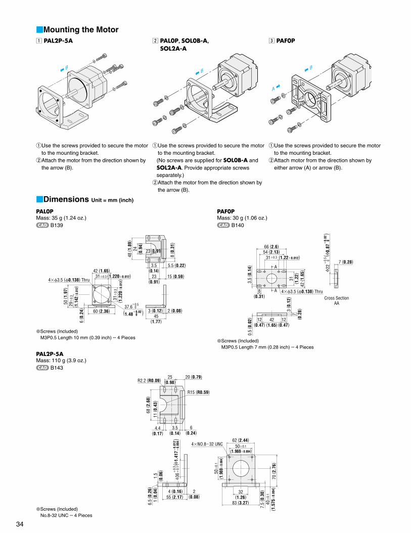
34
Mounting the Motorz PAL2P-5A
B
q Use the screws provided to secure the motor to the mounting bracket.
w Attach the motor from the direction shown by the arrow (B).
x PAL0P, SOL0B-A,SOL2A-A
B
qUse the screws provided to secure the motor to the mounting bracket.(No screws are supplied for SOL0B-A and SOL2A-A. Provide appropriate screws separately.)
w Attach the motor from the direction shown by the arrow (B).
c PAF0P
B
A
q Use the screws provided to secure the motor to the mounting bracket.
w Attach motor from the direction shown by either arrow (A) or arrow (B).
Dimensions Unit = mm (inch)
PAL0PMass: 35 g (1.24 oz.)
B139
310.3 (1.2200.012)43.5 (0.138) Thru
23 (0.91)
8 ( 0
.31)
23(0.91)
15 (0.59)
3.5(0.14)
5.5 (0.22)
45(1.77)
3 (0.12) 2 (0.08)
42 (1.65)
60 (2.36)
6 ( 0
.24)
50 ( 1
.97)
31
0.3
( 1.2
20
0.01
2)
24( 0
.94)
48 ( 1
.89)
29
0.3
( 1.1
42
0.01
2)
37.6 00.5
(1.48 0 )0.02
Screws (Included)M3P0.5 Length 10 mm (0.39 inch) 4 Pieces
PAF0PMass: 30 g (1.06 oz.)
B140
A
A 43.5 (0.138) Thru
42 ( 1
.65)
3 ( 0
.12)
7( 0
.28)
0.5
( 0.0
2)
7 (0.28)310.3 (1.220.012)
54 (2.13)66 (2.6)
31( 1
.22)8
(0.31)
3.5
( 0.1
4)
12(0.47)
12(0.47)
42(1.65)
22
0
0.
5(
0.87
0
)
0.02
Cross SectionAA
Screws (Included)M3P0.5 Length 7 mm (0.28 inch) 4 Pieces
PAL2P-5AMass: 110 g (3.9 oz.)
B143
4NO.832 UNC
7.5
( 0.3
0)40
0.
1
(1.5
75
0.00
4 )70
( 2.7
6)
32(1.26)
83 (3.27)
62 (2.44)
4 (0.16) 2(0.08)
68 ( 2
.68)
4.4(0.17)
11 ( 0
.43)
25(0.98)
6.5
( 0.2
6)
500.1
(1.9690.004)
50
0.1
(1.9
69
0.00
4)
55 (2.17)
R2.2 (R0.09)
R15 (R0.59)
20 (0.79)
6(0.24)
3.5(0.14)
1.5
( 0.0
6)1
( 0.0
4)
0.
012
0.
004
1.
417
()
0.
3
0.1
36
Screws (Included)No.8-32 UNC 4 Pieces

35
SOL0B-AMass: 85 g (3 oz.)
B267
20 (0.79)6 (0.24)
36
( 1.
42)
40 (1.57)88 (3.46)
56 (2.20)
9 ( 0
.35)
4.4
( 0.1
7)
7.4 (0.29)
1 ( 0
.04)
44 (1.73)
1 ( 0
.04)
8 ( 0
.31)
41 ( 1
.61)
62 ( 2
.44)
40
0.5
( 1.5
70.
02)
43.8
0.3
( 1.724
0.012
)
44.5 (0.177) Thru
72 (2.83)20
(0.79)
20( 0
.79)
14 ( 0
.55)
21 (0.83)
SOL2A-AMass: 120 g (4.2 oz.)
B268
22 (0.87) 6 (0.24)3 (0.12)
54
( 2.
13)
50
( 1.
97)
50 (1.97)108 (4.25)
5.4
( 0.2
13)
25( 0
.98)
15( 0
.59)
8.4 (0.33)
9 ( 0
.35)
1 ( 0
.04)
1 ( 0
.04)
8 ( 0
.31)
54 ( 2
.13)
82 ( 3
.23)
50
0.5
( 1.9
70.
02)
44.5 (0.177) Thru
93 (3.66)30 (1.18)
78 (3.07)62 (2.44)
70
0.3
(2.7
65
0.01
2)
31( 1
.22)

36
Flexible Couplings
Coupling Selection Table
Package Model Gear RatioOuter Diameter
of Shaftmm (in.)
TypeDriven Shaft Diameter mm (in.)
4(0.1575)
5(0.1969)
6(0.2362)
6.35(0.2500)
8(0.3150)
10(0.3937)
12(0.4724)
14(0.5512)
15(0.5906)
16(0.6299)
CRK513PP 4 (0.1575)
MCS14
CRK52PP
5 (0.1969)
CRK52PMPCRK54PCRK54PPCRK54PMPCRK523PP-T 7.2, 10, 20, 30CRK543P-T3.6 6 (0.2362)
CRK543P-T 7.2, 10 6 (0.2362)
MCS20
CRK564PCRK566P
8 (0.3150)
CRK523PP-N 5, 7.2, 10CRK544P-N 5, 7.2 10 (0.3937)
CRK543P-T 20, 30 6 (0.2362)
MCS30
CRK56P
8 (0.3150) CRK564PMPCRK566PMPCRK564P-T 3.6, 7.2CRK569PMPCRK544P-N10 10 (0.3937)
CRK564P-T 10, 20, 30 8 (0.3150)MCS40
CRK543P-H 50, 100 10 (0.3937)
CRK566P-N 5, 7.2 12 (0.4724)
CRK566P-N10
12 (0.4724) MCS55 CRK564P-N 25, 36, 50CRK564P-H 50, 100
Enter the motor case length in the box () within the model name.Enter A (Single shaft) or B (Double shaft) in the box () within the model name.Enter the gear ratio in the box () within the model name.
Features of MCS CouplingsThis three-piece coupling adopts an aluminum alloy hub and a resin spider. The simple construction ensures that the high torque generated by a geared motor can be transmitted reliably. The proper elasticity of the spider suppresses motor vibration.
High strength (usable for geared motor) has been realized.A spider (material: polyurethane) controls the vibration generated by the motor.No backlash.
Product Number Code
MCS 30 08 12q w e r
q MCS Couplingsw Outer Diameter of Couplinge Inner Diameter d1 (Smaller Side) [F04 represents 6.35 mm (0.25 in.)]r Inner Diameter d2 (Larger Side) [F04 represents 6.35 mm (0.25 in.)]
A flexible coupling ideal for your motor is available. Once you have decided on a motor and/or gear, you can select the recommended coupling easily. All motor shaft diameters of stepping motor packages are available (including geared motors).
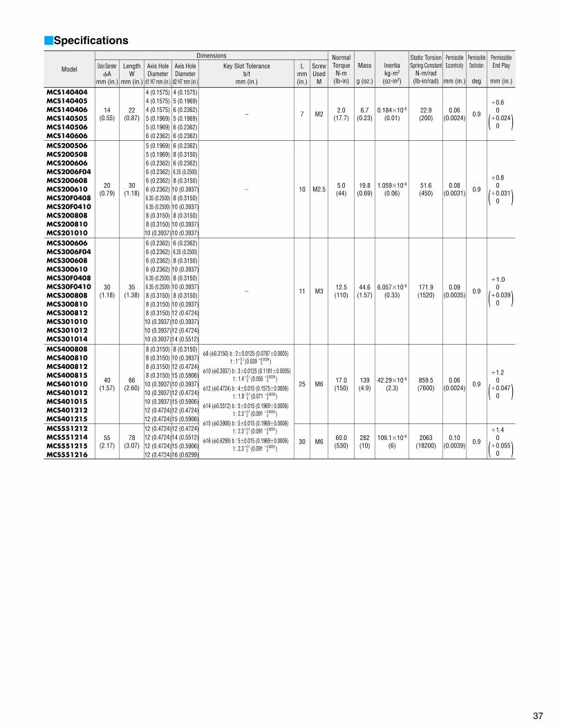
37
Specifications
Model
Dimensions NormalTorqueN·m
(lb-in)
Mass
g (oz.)
Inertiakg·m2
(oz-in2)
Static TorsionSpring Constant
N·m/rad(lb-in/rad)
PermissibleEccentricity
mm (in.)
PermissibleDeclination
deg
PermissibleEnd Play
mm (in.)
Outer DiameterA
mm (in.)
LengthW
mm (in.)
Axis HoleDiameter
d1 H7 mm (in.)
Axis HoleDiameter
d2 H7 mm (in.)
Key Slot Toleranceb/t
mm (in.)
Lmm(in.)
ScrewUsed
M
MCS140404MCS140405MCS140406MCS140505MCS140506MCS140606
14(0.55)
22(0.87)
4 (0.1575)4 (0.1575)4 (0.1575)5 (0.1969)5 (0.1969)6 (0.2362)
4 (0.1575)5 (0.1969)6 (0.2362)5 (0.1969)6 (0.2362)6 (0.2362)
7 M2 2.0(17.7)
6.7(0.23)
0.18410-6
(0.01)22.9(200)
0.06(0.0024) 0.9
0.6 00.024 0
MCS200506MCS200508MCS200606MCS2006F04MCS200608MCS200610MCS20F0408MCS20F0410MCS200808MCS200810MCS201010
20(0.79)
30(1.18)
5 (0.1969)5 (0.1969)6 (0.2362)6 (0.2362)6 (0.2362)6 (0.2362)6.35 (0.2500)6.35 (0.2500)8 (0.3150)8 (0.3150)10 (0.3937)
6 (0.2362)8 (0.3150)6 (0.2362)6.35 (0.2500)8 (0.3150)10 (0.3937)8 (0.3150)10 (0.3937)8 (0.3150)10 (0.3937)10 (0.3937)
10 M2.5 5.0(44)
19.8(0.69)
1.05910-6
(0.06)51.6(450)
0.08(0.0031) 0.9
0.8 00.031 0
MCS300606MCS3006F04MCS300608MCS300610MCS30F0408MCS30F0410MCS300808MCS300810MCS300812MCS301010MCS301012MCS301014
30(1.18)
35(1.38)
6 (0.2362)6 (0.2362)6 (0.2362)6 (0.2362)6.35 (0.2500)6.35 (0.2500)8 (0.3150)8 (0.3150)8 (0.3150)10 (0.3937)10 (0.3937)10 (0.3937)
6 (0.2362)6.35 (0.2500)8 (0.3150)10 (0.3937)8 (0.3150)10 (0.3937)8 (0.3150)10 (0.3937)12 (0.4724)10 (0.3937)12 (0.4724)14 (0.5512)
11 M3 12.5(110)
44.6(1.57)
6.05710-6
(0.33)171.9(1520)
0.09(0.0035) 0.9
1.0 00.039 0
MCS400808MCS400810MCS400812MCS400815MCS401010MCS401012MCS401015MCS401212MCS401215
40(1.57)
66(2.60)
8 (0.3150)8 (0.3150)8 (0.3150)8 (0.3150)10 (0.3937)10 (0.3937)10 (0.3937)12 (0.4724)12 (0.4724)
8 (0.3150)10 (0.3937)12 (0.4724)15 (0.5906)10 (0.3937)12 (0.4724)15 (0.5906)12 (0.4724)15 (0.5906)
8 (0.3150) b : 20.0125 (0.07870.0005) t : 10.1 (0.039 0.0039 ) 0 0
10 (0.3937) b : 30.0125 (0.11810.0005) t : 1.40.1 (0.055 0.0039 ) 0 0
12 (0.4724) b : 40.015 (0.15750.0006) t : 1.80.1 (0.071 0.0039 ) 0 0
14 (0.5512) b : 50.015 (0.19690.0006) t : 2.30.1 (0.091 0.0039 ) 0 0
15 (0.5906) b : 50.015 (0.19690.0006) t : 2.30.1 (0.091 0.0039 ) 0 0
16 (0.6299) b : 50.015 (0.19690.0006) t : 2.30.1 (0.091 0.0039 ) 0 0
25 M6 17.0(150)
139(4.9)
42.2910-6
(2.3)859.5(7600)
0.06(0.0024) 0.9
1.2 00.047 0
MCS551212MCS551214MCS551215MCS551216
55(2.17)
78(3.07)
12 (0.4724)12 (0.4724)12 (0.4724)12 (0.4724)
12 (0.4724)14 (0.5512)15 (0.5906)16 (0.6299)
30 M6 60.0(530)
282(10)
109.110-6
(6)2063
(18200)0.10
(0.0039) 0.9
1.4 00.055 0
( )
( )
( )
( )
( )
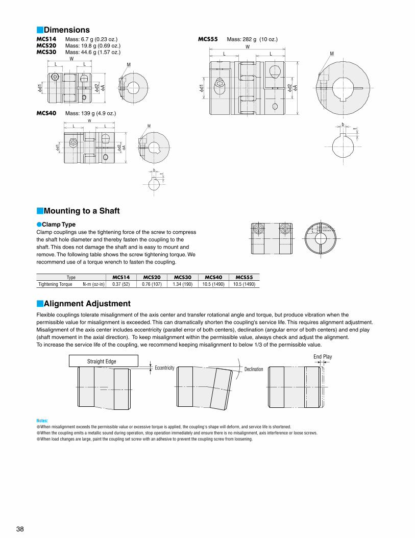
38
Mounting to a Shaft
Clamp TypeClamp couplings use the tightening force of the screw to compress the shaft hole diameter and thereby fasten the coupling to the shaft. This does not damage the shaft and is easy to mount and remove. The following table shows the screw tightening torque. We recommend use of a torque wrench to fasten the coupling.
Type MCS14 MCS20 MCS30 MCS40 MCS55Tightening Torque N·m (oz-in) 0.37 (52) 0.76 (107) 1.34 (190) 10.5 (1490) 10.5 (1490)
Alignment AdjustmentFlexible couplings tolerate misalignment of the axis center and transfer rotational angle and torque, but produce vibration when the permissible value for misalignment is exceeded. This can dramatically shorten the coupling's service life. This requires alignment adjustment. Misalignment of the axis center includes eccentricity (parallel error of both centers), declination (angular error of both centers) and end play (shaft movement in the axial direction). To keep misalignment within the permissible value, always check and adjust the alignment.To increase the service life of the coupling, we recommend keeping misalignment to below 1/3 of the permissible value.
Straight EdgeEccentricity
End Play
Declination
Notes:When misalignment exceeds the permissible value or excessive torque is applied, the coupling's shape will deform, and service life is shortened.When the coupling emits a metallic sound during operation, stop operation immediately and ensure there is no misalignment, axis interference or loose screws.When load changes are large, paint the coupling set screw with an adhesive to prevent the coupling screw from loosening.
DimensionsMCS14 Mass: 6.7 g (0.23 oz.)MCS20 Mass: 19.8 g (0.69 oz.)MCS30 Mass: 44.6 g (1.57 oz.)
d1
d2 A
MLLW
MCS40 Mass: 139 g (4.9 oz.)W
L L
d1
d2 A
b
t
M
MCS55 Mass: 282 g (10 oz.)W
L L
d1
d2 A
M
b
t

39
Clean Dampers
Mechanical dampers suppress stepping motor vibration and improve high-speed performance. An inertia body and silicon gel are hermetically sealed in a plastic case.
FeaturesExcellent vibration absorption
The doughnut-shaped internal inertia body and silicon gel absorb vibration. This feature enables a stable damping effect.
Since there is no frictional dust as in conventional magneticdampers, it can be used in environments where higher degrees of cleanness is needed.
High reliability. It holds up well in harsh environments and changes little with age
because the silicon gel and plastic case used are heat resistant.Machine part is sealed hermetically in a plastic case.
This ensures safety and doesn't generate noise.
Ring
Silicon Gel
Inertia Body
CaseShaft Holes
VEXT
A
VEXT
A
VEXTA
VEXTA
Product LineModel Inertia
kg·m2 (oz-in2)Massg (lb.) Applicable Motor
D4CL-5.0F 34107
(0.186)24
(0.053)
CRK52PBPCRK52PMBPCRK523PBP-T
CRK523PBP-N
CRK54BPCRK54PBPCRK54PMBPCRK543BP-T
CRK544BP-N
CRK543BP-H
D6CL-8.0F 140107
(0.77)61
(0.13)
CRK56BPCRK56PMBPCRK564BP-T
CRK56BP-N
CRK564BP-H
Ambient Temperature: 20C80C (4F176F) Enter the motor case length in the box () within the model name.
Enter the gear ratio in the box () within the model name.
Installation of the Clean DamperPoint the mounting screws of the clean damper toward the motor case, fasten to the shaft and tighten the damper's mounting screws (2 places) with a hexagonal wrench to secure it to the shaft.
Type D4CL-5.0F D6CL-8.0FTightening Torque N·m (oz-in) 0.4 (56) 1.5 (210)
Notes: There are mounting screws with hexagonal holes in two damper locations, so tighten them
both before running the motor. The damper rotates at the same speed as the motor shaft, so do not touch it while the motor
is running.
Dimensions Unit = mm (inch)
d1
d1
B
CD
A
2E
Model d1 A B C D E
D4CL-5.0F 0.018 5 0
0.00070.1969 0
360.5(1.420.02)
130.5(0.510.02)
90.3(0.3540.012)
150.5(0.5910.012) M3
D6CL-8.0F 0.022 8 0
0.00090.3150 0
44.50.5(1.750.02)
200.5(0.790.02)
150.3(0.5910.012)
220.5(0.870.02) M4
<Clean Damper Structure>
( )
( )
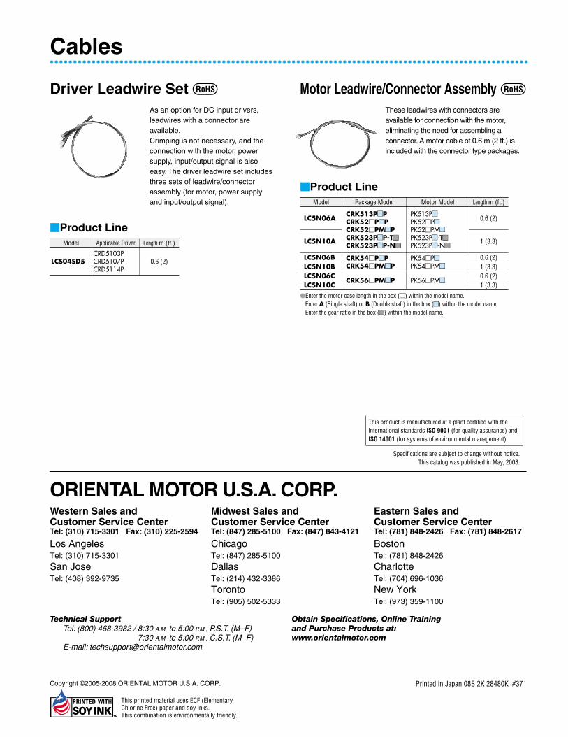
Driver Leadwire Set As an option for DC input drivers, leadwires with a connector are available.Crimping is not necessary, and the connection with the motor, power supply, input/output signal is also easy. The driver leadwire set includes three sets of leadwire/connector assembly (for motor, power supply and input/output signal).
Product LineModel Applicable Driver Length m (ft.)
LCS04SD5CRD5103PCRD5107PCRD5114P
0.6 (2)
Motor Leadwire/Connector Assembly These leadwires with connectors are available for connection with the motor, eliminating the need for assembling a connector. A motor cable of 0.6 m (2 ft.) is included with the connector type packages.
Product LineModel Package Model Motor Model Length m (ft.)
LC5N06ACRK513PPCRK52PPCRK52PMPCRK523PP-T
CRK523PP-N
PK513P
PK52P
PK52PM
PK523P-T
PK523P-N
0.6 (2)
LC5N10A 1 (3.3)
LC5N06B CRK54PPCRK54PMP
PK54P
PK54PM
0.6 (2)LC5N10B 1 (3.3)LC5N06C
CRK56PMP PK56PM0.6 (2)
LC5N10C 1 (3.3)
Enter the motor case length in the box () within the model name.Enter A (Single shaft) or B (Double shaft) in the box () within the model name.Enter the gear ratio in the box () within the model name.
Cables
This product is manufactured at a plant certified with the international standards ISO 9001 (for quality assurance) and ISO 14001 (for systems of environmental management).
Specifications are subject to change without notice.This catalog was published in May, 2008.
ORIENTAL MOTOR U.S.A. CORP.Western Sales andCustomer Service CenterTel: (310) 715-3301 Fax: (310) 225-2594
Los AngelesTel: (310) 715-3301
San JoseTel: (408) 392-9735
Midwest Sales andCustomer Service CenterTel: (847) 285-5100 Fax: (847) 843-4121
ChicagoTel: (847) 285-5100
DallasTel: (214) 432-3386
TorontoTel: (905) 502-5333
Eastern Sales andCustomer Service CenterTel: (781) 848-2426 Fax: (781) 848-2617
BostonTel: (781) 848-2426
CharlotteTel: (704) 696-1036
New YorkTel: (973) 359-1100
Technical SupportTel: (800) 468-3982 / 8:30 A.M. to 5:00 P.M., P.S.T. (M–F)
7:30 A.M. to 5:00 P.M., C.S.T. (M–F)E-mail: [email protected]
Obtain Specifications, Online Training and Purchase Products at: www.orientalmotor.com
Printed in Japan 08S 2K 28480K #371Copyright ©2005-2008 ORIENTAL MOTOR U.S.A. CORP.
This printed material uses ECF (Elementary Chlorine Free) paper and soy inks. This combination is environmentally friendly.