aligning levels of development and … ho.pdfaligning levels of development and principles of...
TRANSCRIPT

ALIGNING LEVELS OF DEVELOPMENT AND PRINCIPLES
OF MEASUREMENT FOR COST PLANNING
Paul H K Ho
City University of Hong Kong
Hong Kong, [email protected]
Abstract
BIM is capable of generating cost estimate directly from a 3D model. It can thus offer a significant
benefit by creating accurate and fast cost plans during different design stages, thereby increasing the
quantity surveyor’s ability in cost planning and control. However, quantity surveyors are generally
reluctant to adopt BIM due to their resistance to change to the model-based quantity take-off and
estimate, data interoperability between BIM and estimating tools, undefined model outputs at various
project stages, and incompatible BIM information classification systems with the traditional elemental
cost planning formats. In order to overcome these problems, this study has proposed a BIM-based pre-
contract cost planning and control framework. Based on the UniFormat information classification system
for model elements, the proposed framework consists of four levels of estimate based on LOD 100, 200,
300 and 350/400 model elements, respectively. It has also incorporated the measurement principles which
are formulated based on the specified amount of graphical and non-graphical information for each model
element. Quantity surveyors can systemically measure individual generic and precise elements or items
according to defined information contents and measurement principles, thus leading to a more accurate
estimate. This study would help significantly improve the industry practice in cost planning and control
and also systemically refine the existing standard method of measurement in alignment with the latest
BIM development.
Keywords: BIM, Pre-contract, Cost Planning.
INTRODUCTION
Building Information Modelling (BIM) has been rapidly developed in the construction industry. It
provides project team members with accurate and reliable information, accommodates various
functional needs, and provides a simulated view of the building. In recent years, BIMs are increasingly
used by employers, architects, structural engineers, building service engineers, quantity surveyors and
contractors during the project lifecycle. As one of the most important tasks in any project, quantity
surveyors undertake cost planning and control to ensure that the ultimate cost will be controlled within
the approved budget.
In the United Stated, Canada and many developed European countries, BIM is very popular in their
construction industries. Realising its potential benefits, the local construction industry is gradually
gaining momentum in the use of BIM. For quantity surveyors, BIM provides both challenges and
opportunities specifically in quantity take-off and cost planning. BIM is capable of automatically
generating quantity take-offs from a 3D model. This is very time consuming if done by manual process.
Therefore, BIM can potentially revolutionise the way how quantity surveyors carry out the pre-contract
cost planning.
In United Kingdom, Australia, Hong Kong and other countries adopting traditional British-style
practices, pre-contract cost planning is largely based on the elemental cost planning and approximate
quantity methods for cost estimating and cost checking, respectively. However, owing to the inadequate
confidence in the reliability of models and lack of recognised standard for categorising building works,
quantity surveyors would favour to adopt the manual take-off approach using paper drawings (Aibinu
and Venkatesh, 2014). Indeed, most BIM-based cost estimating tools such as QTO, Vico, Tocoman and
Innovaya are developed to suit the United States and European markets without considering the UK’s

traditional measurement rules and estimating practices. In addition, the BIM information classification
systems developed in the United States are also not compatible with the UK’s traditional elemental cost
analysis and cost planning formats. As a result, a BIM model cannot be directly used without certain
adjustments. Therefore, quantity surveyors are slow in the use of BIM due to four main problems;
namely, resistance to change to the model-based quantity take-off, suitability of information
classification systems into BIM applications, determination of levels of model detail at various project
stages, and data exchange between BIM and quantity take-off tools (Firat et al, 2010).
Undeniably, the construction industry needs to improve its efficiency by better coordinating the overall
construction process among various project team members. Serving as a collaborative working platform,
BIM projects can progress more effective and faster as it helps address much inefficiency encountered
in traditional projects. By extracting quantities directly from a building model, BIM offers a significant
benefit by creating accurate, fast and consistent cost plans throughout different design stages, thus
enhancing the quantity surveyor’s ability in cost planning and control and reducing the abortive cost of
design changes. This study aims to develop a BIM-based pre-contract cost planning framework in order
to overcome the problems identified above.
REVIEW OF BIM DEVELOPMENT IN COST ESTIMATING AND COST PLANNING
When BIM first came into use, it was seen simply as a 3D model of a building. However, such a basic
explanation does not adequately convey the potential of digital, object-based, interoperable BIM processes
and tools. Once a model is properly developed, information contained within the model can be extracted
for programming (4D BIM), estimating (5D BIM), component fabrication and finally, facility management.
Pre-contract cost planning is one of these important tasks that can benefit from BIM. However, it is
essential to review the relevant development, limitations and corresponding changes in the current cost
planning practice.
BIM-based Cost Planning Process
When preparing a cost plan, quantity surveyors traditionally start by digitising the design consultants’ paper
drawings or directly importing their electronic drawings into estimating software, and then manually take
off quantities from these drawings. This manual take-off method may introduce human errors. By using
BIM, the quantity take-off can be generated from the 3D model. When there is any change in the original
model, the change can instantaneously update the quantity take-offs and estimating documents. Quantity
surveyors can then monitor the cost implication of any design changes.
While the time required for preparing a cost plan varies from project to project, quantity surveyors may
spend at least 60% of their time on quantity take-off. Therefore, there is a great advantage of using a BIM
for cost planning. When manual take-off is no longer necessary, quantity surveyors can save both staffing
cost and time, while reducing the potential for human error.
Through automating the time consuming task of quantity take-off by BIM, quantity surveyors can
concentrate their attention on valuable project-specific issues such as analysing future construction market
trends, evaluating different procurement strategies, examining alternative design solutions, generating
accurate pricing, undertaking value engineering, evaluating risks, etc. These are essential for a high quality
cost plan. This is also the real value of quantity surveyors.
Linking between BIM Software and Cost Estimating Software
The first step in any cost planning is quantity take-off according to the given design information. The
computable information from a BIM model significantly minimises this quantity take-off process. There
are three alternative approaches to utilise BIM for quantity take-off and estimating (Autodesk, 2007;
Eastman et al, 2011). The first approach is to export BIM quantities to an estimating tool. Most BIM design
tools (like Revit) are capable of extracting and exporting quantity data in a text file. On the other hand,

Excel is capable of importing a text file to become a spreadsheet which enables quantity surveyors to carry
out estimating. Due to its simplicity and ease of use, Excel is the most commonly used software.
The second approach is to link BIM design tool via an application programming interface (API) to a
commercially available estimating tool or plug-in (like Nomitech and Innovaya). From within a BIM model,
quantity surveyors export s BIM model according to the data format of the estimating tool. After importing
the file by the estimating tool, quantity surveyors carry out estimating with or without an external cost
database. When compared with Excel, the estimating tool provides some useful features for quantity take-
off and estimating.
The third approach is to use BIM-specialized take-off and estimating tool which is capable of importing
any BIM models in the IFC format. Examples of these include CostX, QTO, Vico and Innovaya. Without
necessarily learning and operating the BIM tool used by design consultants, quantity surveyors directly use
their own estimating tool for quantity take-off, estimating, bill production and other cost management
functions. This estimating tool provides many supporting features for both automated extraction and
manual quantity take-off. In addition, any subsequent changes to the original design model can also be
detected by the estimating tool. It highlights old objects that have been changed, as well as new objects that
have not been included in the previous estimate. When compared with the second approach, the specialized
estimating tool is more powerful and becomes more popular.
Data Interoperability across Different Software
When preparing a cost plan, quantity surveyors often need to import quantity data from BIM models
prepared by design consultants. A common data format is required to enable the sharing of information
between project participants. In order to exchange data across various software tools, BuildingSMART has
developed common data format called the Industry Foundation Classes (IFC) schema to define how
information is provided and stored. As IFC is an open format, it does not belong to any software vendor.
Nowadays, most (if not all) BIM applications have implemented IFC. The latest IFC 2x4 version is able
to represent a very comprehensive range of construction information. As the possible construction
information is huge, there are limitations in the IFC coverage.
Ma et al (2011) examined the application of the IFC standard to the cost estimate in China and found
that the IFC standard, as a whole, is able to describe these seven areas of information. However, in order
to support the data exchange with relevant application tools used in China, some additional property
sets and proxy elements must be added to the current IFC standard.
In assessing the impact of the RICS’s new rules of measurement for cost planning (NRM1) on BIM
schema, Matipa et al (2010) found that there are 53 entities in IfcSharedBuildingElements, but none is
directly related to the cost planning process. The NRM1 does mention the potential application of the
BIM-based data available in the market. As such, the incorporation of information requirements from
the NRM1 into the IFC schema is an important step to enhance the efficiency and consistency of the
UK’s cost planning process. The greatest challenge is the development of data types which can be
recognized by IFC. This requires a quantity surveyor’s mind with software knowledge that models the
cost planning process.
Levels of Development
In a collaborative working environment, project team members are required to produce their models
using standardised processes and practices so as to enable the information exchange throughout the
project lifecycle. In order to ensure the reliability of information output, the American Institute of
Architects (AIA) has developed the levels of development (LOD) concept to describe the levels of
completeness of a model element. The AIA (2013) defines five LODs; namely, the conceptual model (LOD
100), approximate model (LOD 200), precise model (LOD3 00), fabrication model (LOD 400) and as-built
model (LOD 500).

In order to implement the LOD concept, it is necessary to further define the geometry and data content of
each model element for each LOD by reference to an industry-wide standard. Based on the AIA’s basic
LOD definition, the US’s BIMForum has developed the LOD specification to enable project team members
to specify the content and reliability of BIMs at various project stages. Individual model authors are allowed
to define their models, thus enabling downstream users to understand the usability and limitations of models
(BIMForum, 2015). However, it is still under development stage.
Information Classification System in BIM and Cost Planning
For seamless exchange of information under a collaborative working environment, the information
classification system used in BIM should be same for cost planning. In the United States, the OmniClass
construction classification system provides a standardised basis for classifying information in the built
environment. This is the most commonly used classification system in BIM. However, in United
Kingdom, the RICS (2012) has published the new rules of measurement (NRM1) for the preparing a
consistent cost plan. NRM1 is considered as the latest industry standard for pre-contract planning and
control in the UK construction industry. As pointed out by Wu et al (2014b), “the measurement
standards in UK (SMM or NRM) are developed independent of the BIM development process.
Inevitably, their classification system and measurement rules have not been taken into consideration of
the BIM development and their information structure is not fully compatible with the BIM data structure”
(p. 542). While the information in BIM can be mapped to the traditional cost planning format through
certain adjustments, it would be more efficiency for quantity surveyors to adopt the same internationally
recognised classification system.
The RICS’s (2012) new rules of measurement (NRM1) does not describe the exact estimating methods
or cost planning techniques, but sets out measurement rules based on levels 1, 2, 3, and 4 for the group
element, element, sub-element and component, respectively. The highest level 4 is to measure
individual components which are used for checking individual cost targets and the overall budget.
However, a BIM model is capable of generating more detailed quantities from its objects, depending
on its completeness or levels of development. Therefore, the traditional cost planning practice must be
changed in order to capture the full benefit of BIM.
REVIEW OF PREVIOUS RESEARCH IN QUANTITY TAKE-OFF AND COST
ESTIMATING
Due to the importance of quantity take-off and cost estimating, a number of research have been
previously undertaken in this area. In a study of the effects of project complexity in terms of
organizational, resource and technical complexities and the use of BIM in cost estimating, Meerveld et
al (2009) found that most BIM models contain insufficient information for cost estimating, thus leading
to many difficulties encountered in the quantity take-off process and also inducing errors in estimating.
In response to these difficulties, estimators usually spend more effort to look for the required
information or add extra allowances to cover uncertainties in an estimate. This study recommends
standardising the levels of detail for the model as well as documenting the information requirements in
order to align the BIM model with the cost estimate. These recommendations are vital for the future
development of BIM-based cost planning.
Shen and Issa (2010) evaluated the effectiveness of BIM-assisted detailed estimating tools based on
four individual parameters such as accuracy, generality, efficiency and flexibility. A multi-attribute
utility model is then used to assess the overall performance. This study concludes that the more
complicated the estimating task is, the clearer the advantages of using BIM-assisted estimating tools
are.
In a study of BIM developments in cost estimating and construction programming, Jiang (2011) found
that BIM can enhance the traditional cost estimating and programming tasks. His study suggests two

future developments: higher levels of detail in the model to facilitate the preparation of a detailed cost
estimate, and linking cost and time parameters for delivery of a scheduled financial analysis.
Kim et al (2012) proposed a hybrid estimating method comprising historical data-based estimating and
assembly-based estimating. When project information is limited, historical data-based method is used
to prepare an estimate. When more project information is available, assembly-based estimating method
is used by measuring the quantity of each element and assessing its unit cost. These two methods are
used either separately or together, depending on the available information. Scrutinising two estimates
reduces the uncertainty arising from equivocal project information.
In a study of the BIM-based design for quantity take-off, Monteiro and Martins (2013) found that
ArchiCAD has an advanced take-off system, but it is not able to extract quantities without to certain
extents altering the model because it does not fully meet estimators' needs in quantity take-off. This
study thus recommends to develop standard modelling approaches in order to improve the output
performance. Again, this is vital for the future development of BIM-based cost planning.
Since most BIM-based take-off and estimating tools are developed outside UK and based on different
quantification rules and practices, Wu et al (2014b) reviewed the functional and technical capabilities
of four estimating tools commonly used in UK. This study found that “majority of the tools (with the
exception of BIMmeasure) do not support the UK practice automatically and additional works are
required to use them in the UK projects (p.558)”. This study concludes that project team members must
agree the information requirement from the viewpoint of cost planning so as to facilitate quantity
surveyors to use BIM more effectively.
Choi et al (2015) suggested an open BIM-based quantity take-off process for cost estimating. The
quantity take-off process consists of four steps: BIM modelling, physical quality verification, property
verification, and quantity take-off. The first step is to develop a building model by BIM authoring tools
which support the IFC format for information exchange. The second step is verify the physical quality
of the BIM model by Solibri Model Checker to ensure the accuracy of quantity information. The third
step is to verify the property by extracting model elements and checking its codes before the actual
quantity take-off. The quality assurance process is important for an accurate quantity take-off.
PROPOSED FRAMEWORK
In order to enable seamless information exchange under a collaborative working platform, the proposed
BIM-based pre-contract cost planning framework is based on the OmniClass/UniFormat classification
system for building elements and the LOD specification for individual model elements. The proposed
framework consists of four levels of estimate but is based on LOD 100, 200, 300 and 350 model elements,
respectively. As LODs are used to define the output information for each model element, this ensures a
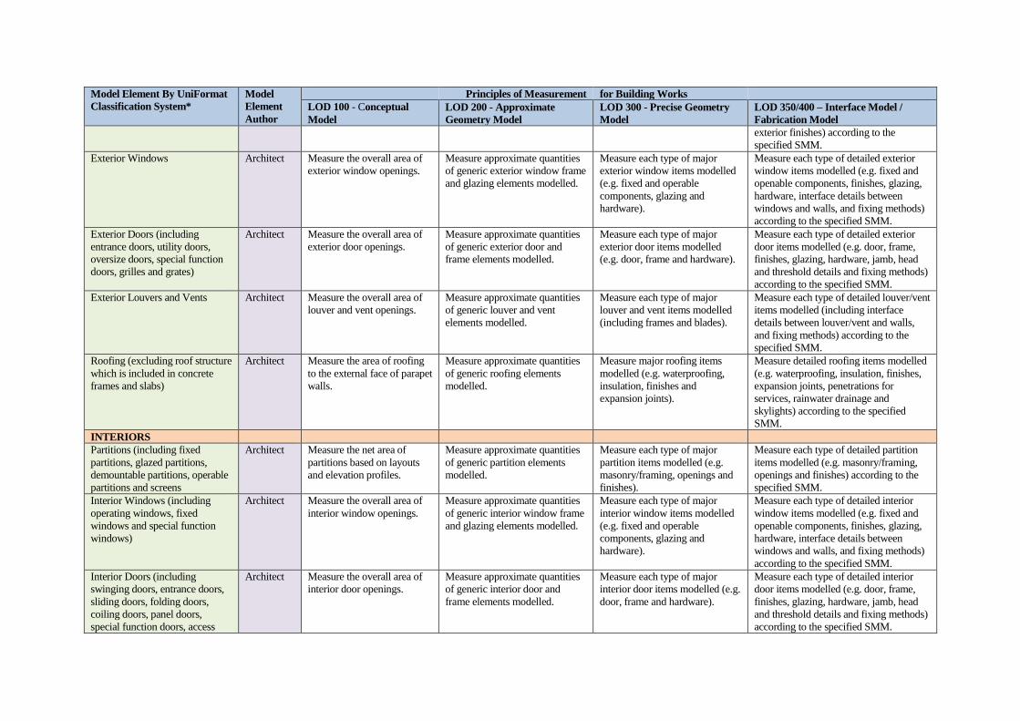
right amount of information for producing a consistent cost estimate. More specifically, the proposed
framework has developed the principles of measurement for each model element at each LOD as shown in
Table 1. As BIM is capable of fully utilising the three dimensions of all objects in the BIM model, it is not
necessary to limit the measurement of building elements to its group elements, elements, sub-elements or
components as the traditional quantity surveyor’s practice. The principles of measurement take full account
of, and are also formulated according to, the amount of both graphical and non-graphical information
defined by LODs for each model element. Under this circumstance, quantity surveyors can systemically
measure individual generic and precise elements/items modelled according to defined information contents
and measurement principles, thus leading to a more accurate measurement and estimate.
It is realised that there is not strict correspondence between LODs and design stages (BIMForum, 2015).
Nevertheless, it is assumed that levels 1, 2, 3 and 4 estimate are based on ‘pure’ LOD 100, 200, 300 and
350/400 models, respectively, which are prepared at the conceptual design, schematic design, design
development and contract documentation stages, respectively.

Table 1: Principles of Measurement for Building Works at Different Levels of Development
Model Element By UniFormat
Classification System*
Model
Element
Author
Principles of Measurement for Building Works
LOD 100 - Conceptual
Model
LOD 200 - Approximate
Geometry Model
LOD 300 - Precise Geometry
Model
LOD 350/400 – Interface Model /
Fabrication Model
SUBSTRUCTURE
Pile Foundations (e.g. concrete
bored piles)
Structural
Engineer
Measure the area of the
lowest floor to the external
face of external walls.
Measure approximate quantities
of generic piling elements
modelled.
Measure major piling items
modelled (e.g. drilling, bell
bottom and concrete).
Measure detailed piling items modelled
(e.g. drilling, casing, bell bottom,
excavation, disposal of excavated
materials, reinforcement and concrete)
according to the specified SMM.
Pile Caps Structural
Engineer
Measure approximate quantities
of generic pile cap and beam
elements modelled.
Measure major pile cap and
beam items modelled (e.g.
concrete, formwork, excavation,
backfill and disposal).
Measure detailed pile cap and beam items
modelled (e.g. concrete, formwork,
reinforcement, water stops, excavation,
backfill and disposal) according to the
specified SMM.
Grade Beams Structural
Engineer
Structural Slabs-on-Grade Structural
Engineer
Measure approximate quantities
of generic slab elements
modelled.
Measure major slab items
modelled (e.g. concrete and
formwork).
Measure detailed slab items modelled
(e.g. concrete, formwork, reinforcement,
expansion joints and water stops)
according to the specified SMM.
SHELL
Concrete Frames: Columns and
Walls
Structural
Engineer
Measure the total gross floor
area of the building to the
external face of external
walls.
Measure approximate quantities
of generic column and wall
elements modelled.
Measure major columns and wall
items modelled (e.g. concrete and
formwork).
Measure detailed column and wall items
modelled (e.g. concrete, formwork and
reinforcement) according to the specified
SMM.
Concrete Frames: Beams Structural
Engineer
Measure major beam items
modelled (e.g. concrete and
formwork).
Measure detailed beam items modelled
(e.g. concrete, formwork and
reinforcement) according to the specified
SMM.
Concrete Floor/Roof Slabs Structural
Engineer
Measure approximate quantities
of generic slab elements
modelled.
Measure major slab items
modelled (e.g. concrete and
formwork).
Measure detailed slab items modelled
(e.g. concrete, formwork, reinforcement,
designed joints, openings and
penetrations) according to the specified
SMM.
Stairs Architect/
Structural
Engineer
Measure the number of
storey flights (i.e. the number
of staircases multiplied by
the number of floors served).
Measure approximate quantities
of generic stair elements
including treads, risers and
railings modelled.
Measure major stair items
modelled (e.g. concrete,
formwork and railings).
Measure detailed stair items modelled
(e.g. concrete, formwork, reinforcement,
railings, and posts or supports) according
to the specified SMM.
Exterior Walls (Concrete) Architect Measure the net area of
external walls based on
exterior elevations.
Measure approximate quantities
of generic external wall elements
modelled.
Measure major exterior wall
items modelled (e.g. concrete,
formwork, openings, interior and
exterior finishes).
Measure detailed exterior wall items
modelled (e.g. concrete, formwork,
reinforcement, openings, interior and
Model Element By UniFormat
Classification System*
Model
Element
Author
Principles of Measurement for Building Works
LOD 100 - Conceptual
Model
LOD 200 - Approximate
Geometry Model
LOD 300 - Precise Geometry
Model
LOD 350/400 – Interface Model /
Fabrication Model
exterior finishes) according to the
specified SMM.
Exterior Windows Architect Measure the overall area of
exterior window openings.
Measure approximate quantities
of generic exterior window frame
and glazing elements modelled.
Measure each type of major
exterior window items modelled
(e.g. fixed and operable
components, glazing and
hardware).
Measure each type of detailed exterior
window items modelled (e.g. fixed and
openable components, finishes, glazing,
hardware, interface details between
windows and walls, and fixing methods)
according to the specified SMM.
Exterior Doors (including
entrance doors, utility doors,
oversize doors, special function
doors, grilles and grates)
Architect Measure the overall area of
exterior door openings.
Measure approximate quantities
of generic exterior door and
frame elements modelled.
Measure each type of major
exterior door items modelled
(e.g. door, frame and hardware).
Measure each type of detailed exterior
door items modelled (e.g. door, frame,
finishes, glazing, hardware, jamb, head
and threshold details and fixing methods)
according to the specified SMM.
Exterior Louvers and Vents Architect Measure the overall area of
louver and vent openings.
Measure approximate quantities
of generic louver and vent
elements modelled.
Measure each type of major
louver and vent items modelled
(including frames and blades).
Measure each type of detailed louver/vent
items modelled (including interface
details between louver/vent and walls,
and fixing methods) according to the
specified SMM.
Roofing (excluding roof structure
which is included in concrete
frames and slabs)
Architect Measure the area of roofing
to the external face of parapet
walls.
Measure approximate quantities
of generic roofing elements
modelled.
Measure major roofing items
modelled (e.g. waterproofing,
insulation, finishes and
expansion joints).
Measure detailed roofing items modelled
(e.g. waterproofing, insulation, finishes,
expansion joints, penetrations for
services, rainwater drainage and
skylights) according to the specified
SMM.
INTERIORS
Partitions (including fixed
partitions, glazed partitions,
demountable partitions, operable
partitions and screens
Architect Measure the net area of
partitions based on layouts
and elevation profiles.
Measure approximate quantities
of generic partition elements
modelled.
Measure each type of major
partition items modelled (e.g.
masonry/framing, openings and
finishes).
Measure each type of detailed partition
items modelled (e.g. masonry/framing,
openings and finishes) according to the
specified SMM.
Interior Windows (including
operating windows, fixed
windows and special function
windows)
Architect Measure the overall area of
interior window openings.
Measure approximate quantities
of generic interior window frame
and glazing elements modelled.
Measure each type of major
interior window items modelled
(e.g. fixed and operable
components, glazing and
hardware).
Measure each type of detailed interior
window items modelled (e.g. fixed and
openable components, finishes, glazing,
hardware, interface details between
windows and walls, and fixing methods)
according to the specified SMM.
Interior Doors (including
swinging doors, entrance doors,
sliding doors, folding doors,
coiling doors, panel doors,
special function doors, access
Architect Measure the overall area of
interior door openings.
Measure approximate quantities
of generic interior door and
frame elements modelled.
Measure each type of major
interior door items modelled (e.g.
door, frame and hardware).
Measure each type of detailed interior
door items modelled (e.g. door, frame,
finishes, glazing, hardware, jamb, head
and threshold details and fixing methods)
according to the specified SMM.

Model Element By UniFormat
Classification System*
Model
Element
Author
Principles of Measurement for Building Works
LOD 100 - Conceptual
Model
LOD 200 - Approximate
Geometry Model
LOD 300 - Precise Geometry
Model
LOD 350/400 – Interface Model /
Fabrication Model
doors and panels, grills and
grates)
Raised Floor (including access
flooring and platform/stage
floors)
Architect Measure the total area of the
raised floor.
Measure approximate quantities
of generic raised floor elements
modelled.
Measure each type of major
raised floor items modelled (e.g.
adjustable pedestal, floors panels,
openings and penetrations).
Measure detailed raised floor items
modelled (e.g. adjustable pedestals, floor
panels, ventilation, outlet boxes, skirtings
and edge trims) according to the specified
SMM.
Suspended Ceiling (including
acoustic, plaster, gypsum and
special function ceilings)
Architect Measure the total area of the
suspended ceiling.
Measure approximate quantities
of generic suspended ceiling
elements modelled.
Measure each type of major
suspended ceiling items
modelled (e.g. ceiling panels,
suspension system, surface
finishes and access panels).
Measure each type of detailed suspended
ceiling items modelled (e.g. ceiling
panels, suspension system, surface
finishes, access panels, cornices and the
like) according to the specified SMM.
Wall Finishes (including tile wall
finish, wall panelling, wall
coverings, wall carpeting, stone
facing, special wall surfacing,
wall painting and coating and
acoustical wall treatment)
Architect Measure the total area of
wall and column finishes.
Measure approximate quantities
of each type of generic wall and
column finish elements
modelled.
Measure each type of major wall
and column finish items
modelled (e.g. tile wall finish,
wall panelling, wall coverings,
wall carpeting, stone facing,
special wall surfacing, wall
painting and coating and
acoustical wall treatment, etc.).
Measure each type of detailed wall and
column finish items modelled (e.g. tile
wall finish, wall panelling, wall
coverings, wall carpeting, stone facing,
special wall surfacing, wall painting and
coating and acoustical wall treatment,
etc.) according to the specified SMM.
Floor Finishes Architect Measure the total area of
floor finishes.
Measure approximate quantities
of each type of generic floor
finish elements modelled.
Measure each type of major floor
finish items modelled (e.g.
surface hardeners, in-situ
finishes, tiled finishes, wooden
finishes and other propriety
flooring, etc.).
Measure each type of detailed floor finish
items modelled (e.g. surface hardeners,
in-situ finishes, tiled finishes, wooden
finishes and other propriety flooring, etc.)
according to the specified SMM.
Ceiling Finishes Architect Measure the total area of
ceiling finishes.
Measure approximate quantities
of each type of generic ceiling
elements modelled.
Measure each type of major
ceiling finish items modelled
(e.g. in-situ coatings, sprayed
coatings, decorative coverings,
painting, cornices and the like).
Measure each type of detailed ceiling
finish items modelled (e.g. in-situ
coatings, sprayed coatings, decorative
coverings, painting, cornices and the like)
according to the specified SMM.
SERVICES
Lifts Building
Service
Engineer
Measure the number of
schematic lift models.
Measure approximate quantities
of each type of generic lift
elements modelled.
Measure each type of major lift
items modelled (e.g. lift car,
doors, lifting equipment, guides
and counter balances).
Measure each type of detailed lift items
modelled (e.g. lift car, doors, lifting
equipment, guides, counter balances, lift
shaft and builder’s works) according to
the specified SMM.
Escalators Building
Service
Engineer
Measure the number of
schematic escalator models.
Measure approximate quantities
of each type of generic escalator
elements modelled.
Measure each type of major
escalator items modelled (e.g.
Measure each type of detailed escalator
items modelled (e.g. escalator, ancillary
components, control, balustrades,

Model Element By UniFormat
Classification System*
Model
Element
Author
Principles of Measurement for Building Works
LOD 100 - Conceptual
Model
LOD 200 - Approximate
Geometry Model
LOD 300 - Precise Geometry
Model
LOD 350/400 – Interface Model /
Fabrication Model
escalator, ancillary components,
control and balustrades).
cladding to sides and soffits, and
builder’s works) according to the
specified SMM.
Sanitary Appliances Architect Measure the number of
schematic sanitary appliance
models.
Measure approximate quantities
of each type of generic sanitary
appliance elements modelled.
Measure each type of major
sanitary appliance items
modelled (e.g. WC pens and
cisterns, sinks, basins, baths,
shower units and taps, etc.).
Measure each type of detailed sanitary
appliance items modelled (e.g. WC pens
and cisterns, sinks, basins, baths, shower
units, taps, sanitary ancillaries, builder’s
works, etc.) according to the SMM.
Cold Water System Building
Service
Engineer
Measure approximate quantities
of schematic layout of generic
cold water elements modelled.
Measure major cold water
system items modelled (e.g. cold
water distribution pipelines to
sanitary appliances and
equipment, pipe fittings, valves,
pumps, pressure booster sets and
control components).
Measure detailed cold water items
modelled (e.g. cold water distribution
pipelines to sanitary appliances and
equipment, pipe fittings, valves, pumps,
pressure booster sets, water tanks, control
components and builder’s works)
according to the specified SMM.
Hot Water System Building
Service
Engineer
Measure approximate quantities
of schematic layout of generic
hot water elements modelled.
Measure major hot water system
items modelled (e.g. hot water
distribution pipelines to sanitary
appliances and equipment, pipe
fittings, valves, pumps,
boilers/heaters, storage cylinders,
insulation and control
components).
Measure detailed hot water items
modelled (e.g. hot water distribution
pipelines to sanitary appliances and
equipment, pipe fittings, valves, pumps,
boiler/heaters, storage cylinders,
insulation, control components and
builder’s works) according to the
specified SMM.
Flushing Water System Building
Service
Engineer
Measure approximate quantities
of schematic layout of generic
flushing water elements
modelled.
Measure major flushing water
system items modelled (e.g.
flushing water distribution
pipelines to sanitary appliances
and equipment, pipe fittings,
valves, pumps, pressure booster
sets and control components).
Measure detailed flushing water items
modelled (e.g. flushing water distribution
pipelines to sanitary appliances and
equipment, pipe fittings, valves, pumps,
pressure booster sets, water tanks, control
components and builder’s works)
according to the specified SMM.
Soil, Waste, Ventilation and
Rainwater Disposal Systems
Building
Service
Engineer
Measure approximate quantities
of schematic layout of generic
soil, waste, ventilation and
rainwater disposal elements
modelled.
Measure major soil, waste,
ventilation and rainwater disposal
system items modelled (e.g. soil,
waste, ventilation and rainwater
pipes, pipe fittings, traps, access
points, collars and sump pumps).
Measure detailed soil, waste, ventilation
and rainwater disposal items modelled
(e.g. soil, waste, ventilation and rainwater
pipes, pipe fittings, traps, access points,
collars, sump pumps and builder’s works)
according to the specified SMM.
Heating Systems Building
Service
Engineer
Measure the area serviced by
the respective system
models.
Measure approximate quantities
of schematic layout of generic
heating elements modelled.
Measure major heating system
items modelled (e.g. boiler plant
and ancillary equipment,
distribution pipelines to heat
Measure detailed heating system items
modelled (e.g. boiler plant and ancillary
equipment, distribution pipelines to heat
emitters or other equipment, pipe fittings,

Model Element By UniFormat
Classification System*
Model
Element
Author
Principles of Measurement for Building Works
LOD 100 - Conceptual
Model
LOD 200 - Approximate
Geometry Model
LOD 300 - Precise Geometry
Model
LOD 350/400 – Interface Model /
Fabrication Model
emitters or other equipment, pipe
fittings, valves, fans and control
components).
valves, fans, control components and
builder’s works) according to the
specified SMM.
Cooling Systems Building
Service
Engineer
Measure approximate quantities
of schematic layout of generic
cooling elements modelled.
Measure major cooling system
items modelled (e.g. cooling
plant and ancillary equipment,
distribution pipelines and
ductwork, fan coil units, air
handling units, pumps, fans,
grilles, filters, other ancillary
components, insulation and
control components).
Measure detailed cooling system items
modelled (e.g. cooling plant and ancillary
equipment, distribution pipelines and
ductwork, fan coil units, air handling
units, pumps, fans, grilles, filters, other
ancillary components, control
components, insulation and builder’s
works) according to the specified SMM.
Ventilation Systems Building
Service
Engineer
Measure approximate quantities
of schematic layout of generic
ventilation elements modelled.
Measure major ventilation
system items modelled (e.g.
distribution ductwork, terminal
units, fan units, grilles, filters,
other ancillary components,
insulation, and control
components).
Measure detailed ventilation system
items modelled (e.g. distribution
ductwork, terminal units, fan units,
grilles, filters, other ancillary
components, insulation, control
components and builder’s works)
according to the specified SMM
Firefighting Systems Building
Service
Engineer
Measure the area serviced by
the respective system
models.
Measure approximate quantities
of schematic layout of generic
hose reel and dry/wet riser
elements modelled.
Measure major firefighting
system items modelled (e.g. fire
reel and dry/wet riser systems, its
distribution pipeline, pipe fittings
and ancillaries, pump sets, inlet
valves and boxes, outlet/landing
valves, and control components
and panels).
Measure detailed firefighting system
items modelled (e.g. fire reel and dry/wet
riser systems, its distribution pipeline,
pipe fittings and ancillaries, pump sets,
inlet valves and boxes, outlet/landing
valves, control components and panels,
water tanks and builder’s works)
according to the specified SMM.
Fire Suppression Systems Building
Service
Engineer
Measure approximate quantities
of schematic layout of generic
sprinkler and gas firefighting
elements modelled.
Measure major fire suppression
system items modelled (e.g. fire
reel and dry/wet riser systems, its
distribution pipeline, pipe fittings
and ancillaries, pump sets, inlet
valves and boxes, outlet/landing
valves, and control components
and panels).
Measure detailed fire suppression system
items modelled (e.g. fire reel and dry/wet
riser systems, its distribution pipeline,
pipe fittings and ancillaries, pump sets,
inlet valves and boxes, outlet/landing
valves, control components and panels,
and builder’s works) according to the
specified SMM.
Electrical Systems Building
Service
Engineer
Measure the area serviced by
the electrical system models.
Measure approximate quantities
of schematic layout of generic
main and sub-main distribution,
power and lighting elements
modelled.
Measure major electrical system
items modelled (e.g.
transformers, switchgears,
distribution boards, HV and LV
cables, trunking, busbar trunking,
Measure detailed electrical system items
modelled (e.g. transformers, switchgears,
distribution boards, HV and LV cables,
trunking, busbar trunking, conduits,
cables, socket outlets, switches,

Model Element By UniFormat
Classification System*
Model
Element
Author
Principles of Measurement for Building Works
LOD 100 - Conceptual
Model
LOD 200 - Approximate
Geometry Model
LOD 300 - Precise Geometry
Model
LOD 350/400 – Interface Model /
Fabrication Model
conduits, cables, socket outlets,
switches, luminaries and lamps,
lighting controls, and earthing
and bonding components).
luminaries and lamps, lighting controls,
earthing and bonding components, and
builder’s works) according to the
specified SMM.
Communication Systems Building
Service
Engineer
Measure the area serviced by
the communication system
models.
Measure approximate quantities
of schematic layout of generic
telecommunication, data
transmission, public address, fire
detection, smoke detection, fire
alarm, television and other
communication elements
modelled.
Measure major communication
system items modelled (e.g.
individual systems, conduit and
wiring, controls, indicator panels
and ancillary equipment).
Measure detailed communication system
items modelled (e.g. individual systems,
conduit and wiring, controls, indicator
panels, ancillary equipment and builder’s
works) according to the specified SMM.
EQUIPMENT AND
FURNISHINGS
Equipment (including vehicle
and pedestrian, commercial,
institutional, residential,
entertainment and recreational
and other equipment)
Building
Service
Engineer
Measure the number of
schematic equipment model.
Measure approximate quantities
of each type of generic
equipment elements modelled.
Measure each type of major
equipment items modelled.
Measure each type of detailed equipment
items modelled according to the specified
SMM.
Furnishings (including fixed and
movable furnishings)
Architect Measure the number of
schematic furnishings model.
Measure approximate quantities
of each type of generic furnishing
elements modelled.
Measure each type of major
furnishing items modelled.
Measure each type of detailed furnishing
items modelled according to the specified
SMM.
Note:
* Other internationally recognised classification system can also be adopted as long as agreeable by all project team members.

Level 1 Estimate at LOD 100
The main purposes of the level 1 estimate are to provide a reliable cost estimate to compare with the
employer’s budget and also to set cost targets for individual elements so that when the design further
progresses, cost targets are checked and modifications are made to the design (where necessary) in order
to control the overall cost within the budget.
Level 1 estimate is prepared after the completion of the conceptual design when the detailed scope of works,
schedule of accommodations and other key performances are fully defined or agreed. Model elements are
based on LOD 100. At this stage, many of the building elements are not yet modelled. Nevertheless, many
descriptive data prepared by design consultants provide useful information for preparing the level 1
estimate. Such data may include the project location, site constraints, building stories, space types, structure
types, exterior enclosure types, internal walls, stairs, equipment, vertical circulation system, plumbing
fixtures, cold, hot and flushing water systems, soil, waste, ventilation and rainwater disposal systems,
HVAC systems, fire fighting and suppression systems, electrical system, communication systems, and
building performance (sustainability) requirements, etc. The principle of measurement is based the
measurement of elemental quantities in terms of the relevant area or number as shown in Table 1. Realising
the limitations of a conceptual model, quantity surveyors must ensure that all available (graphical and non-
graphical) information which may have an impact on the estimate is taken into consideration.
The pricing of each measured elemental quantity is based on the corresponding elemental unit rate obtained
from cost analyses of previously similar projects or benchmark analyses. Level 1 estimate provides the
frame of reference for level 2 estimate.
Level 2 Estimate at LOD 200
Level 2 estimate is a progression of the level 1 estimate. The main purposes of the level 2 estimate are to
provide a more accurate cost estimate and also to check cost targets set for individual elements/sub-
elements in order to control the overall cost within the budget.
Level 2 estimate is prepared after the completion of the schematic design stage. Architectural, structural
and building service model elements are based on LOD 200. Model elements are generic and without
specific details, but provide useful graphical and non-graphical information for preparing the level 2
estimate. At this stage, a comprehensive range of generic models is available including pile foundations,
structural frames and slabs, stairs, exterior walls, windows and doors, louvers and vents, roofing, partitions,
interior windows and doors, raised floor, suspended ceiling, wall, floor and ceiling finishes, equipment,
lifts and escalators, sanitary appliances, cold, hot and flushing water systems, soil, waste, ventilation and
rainwater disposal systems, HVAC systems, fire fighting and suppression systems, electrical system,
communication systems and building performance (sustainability) requirements, etc. Since each of model
elements at LOD 200 is approximately modelled in terms of quantities, size, and shape, the principle of
measurement is based on the measurement of composite items modelled as shown in Table 1.
The pricing for each measured composite item is based on the corresponding composite unit rate by
grouping the current market price of several items together or a specific database for composite items at
LOD 200. Level 2 estimate provides the frame of reference for level 3 estimate, and also provides a cost
check against each cost target established at level 1 estimate. Level 2 estimate may be used for value
engineering applications before the completion of specifications and design drawings.
Level 3 Estimate at LOD 300
Level 3 estimate is a progression of the level 2 estimate. The main purpose of the level 3 estimate is to
check cost targets of individual elements/sub-elements in order to control the overall budget.

Level 3 estimate is prepared after the completion of the design development stage where technical designs
and specifications are available. All model elements are based on LOD 300. Quantity surveyors
traditionally measure detailed construction works according to their published standard method of
measurement. Since each model element at LOD 300 is accurate in terms of quantity, size and shape, the
principle of measurement is measured based on the specified standard method of measurement (SMM)
whenever possible. The resulting pricing document comprises a large number of items in each work
section/package similar to an (approximate) bills of quantities.
The pricing for each measured item is based on the corresponding unit rate obtained from a database on
market prices. Minor items not modelled are ignored in the measurement, but are taken into account by
adjusting the unit rate by an appropriate percentage. Level 3 estimate provides a cost check against each
cost target established at level 2 estimate.
Level 4 Estimate at LOD 350 / LOD 400
Level 4 estimate is the pre-tender estimate. The main purpose of the level 4 estimate is to provide an
accurate preview of the tender figure in order to alert the design team to the possible cost problems and
allow them to quickly effect any changes where necessary. However, some quantity surveyors consider
that this exercise serves no useful pre-contract cost control purposes, as the whole design have already been
completed.
Level 4 estimate is prepared after the completion of the contract documentation stage where all designs,
specifications and tender documents are available. For the preparation of bills of quantities, model elements
at LOD 300 may or may not be adequate, depending on the particular standard method of measurement
used. In some (but not all) elements, the level of model details required may be up to LOD 350 or even
LOD 400 so that various interface and fabrication details can also be measured and incorporated in the
tender documents. Therefore, the principle of measurement is based on the specified standard method of
measurement (SMM). The resulting pricing document is bills of quantities.
The pricing of each measured item is based on the corresponding unit rate obtained from a cost database.
Pricing bills of quantities provides the most accurate estimate of the likely tender figure. It can be used to
evaluate the reasonableness of returned tenders.
Estimates for Different Procurement Strategies
While the above four levels of estimate are based on its pure form, the same principle is applicable to
various procurement strategies. For instance, an architectural model up to LOD 200 is prepared for a design-
and-build project. Under such a situation, the generic model can be measured and priced according to the
principle as described for the level 2 estimate.
In addition, a particular project may be broken down into various work packages (such as foundation works,
precast concrete components, curtain walls, building service installations and other specialist works) which
are tendered under different procurement methods and at different project stages. Again, the appropriate
work package models can be measured and priced according to the principle as described above.
DISCUSSIONS AND CONCLUSIONS
Quantity surveyors prepare cost plans 1, 2 and 3 based on the measurement and pricing of group elements,
elements, sub-elements and components (RICS, 2012), whereas the proposed levels 1, 2 and 3 estimate
based on the measurement of LOD 100 sub-elements, LOD 200 generic elements and LOD 300 precise
elements respectively provide a more detailed measurement and pricing, thus leading to a more accurate
estimate. In addition, quantity surveyors’ traditional cost plans heavily rely on the availability of
information and there is no explicit information requirement to be exchanged at each design stage. However,
based on the proposed framework, the information output for each model element is clearly defined with

reference to LODs. This ensures that reliable information is available for preparing the appropriate levels
of estimate. Furthermore, when preparing a traditional cost plan, there is no explicit rules for the
measurement of detailed items other than simple measurement rules for elements, sub-elements and
components (RICS, 2012). In order to ensure a systematic measurement, the proposed framework has
incorporated specific measurement principles for each model element at different LODs. This ensures that
model elements at different LODs are measured according to specified information contents and
measurement rules.
In order to help quantity surveyors capture the benefits of BIM, this study has proposed a BIM-based
cost planning framework which comprises four levels of estimate. Each level of estimate aligns with
four key parameters; namely, (1) the model elements based on the internationally recognised
OmniClass/UniFormat classification system, (2) the output information defined at LOD 100, 200, 300 and
350/400, (3) the project stages such as the conceptual design, schematic design, design development and
contract documentation stages, and (4) the principles of measurement formulated according to the specified
amount of graphical and non-graphical information at different LODs. For the preparation of each level of
estimate, quantity surveyors can systemically extract quantities from individual generic/precise
elements/items modelled according to specified measurement principles, thus providing a more accurate
estimate. It is expected that the proposed framework would help improve the industry practice in cost
planning and also help review the existing standard methods of measurement in alignment with the latest
BIM development.
REFERENCES
Aibinu, A. and Venkatesh, S. (2014), Status of BIM Adoption and the BIM Experience of Cost
Consultants in Australia, Journal of Professional Issues and Engineering Education Practice, 140(3).
American Institute of Architects (AIA) (2013), AIA Document G202 – 2013 Project Building
Information Modelling Protocol Form, AIA.
Autodesk (2007), BIM and Cost Estimating, retrieved from http://www.google.com.hk/
BIMForum (2015), Level of Development Specification for Building Information Models, Version 2015.
Cheung, F.K.T., Rihan, J., Tah, J., Duce, D. and Kurul, E. (2012), Early Stage Multi-level Cost Estimation
for Schematic BIM Models, Automation in Construction, 27, 67-77.
Choi, J., Kimb, H. and Kim, I. (2015), Open BIM-based Quantity Take-off System for Schematic
Estimation of Building Frame in Early Design Stage, Journal of Computational Design and
Engineering, 2, 16-25.
Construction Industry Council (CIC) (2013), Building Information Model (BIM) Protocol, CIC, London.
Eastman, C., Teicholz, P., Sacks, R. and Liston, K. (2011), BIM Handbook: A Guide to Building
Information Modeling for Owners, Managers, Designers, Engineers, and Contractors, John Wiley &
Sons, Inc., New Jersey.
Firat, C.E., Arditi, D., Hamalainen, J.P., Stenstrand, J. and Kiiras, J. (2010), Quantity Take-off in Model-
Based Systems, Proceedings of the CIB W78 2010: 27th International Conference, Cairo, Egypt, 16-
18 November.
Jiang, X. (2011), Developments in Cost Estimating and Scheduling in BIM Technology, Civil Engineering
Master's Theses, Northeastern University, Massachusetts.
Kim, H.J., Seo, Y.C. and Hyun, C.T. (2012), A Hybrid Conceptual Cost Estimating Model for Large
Building Projects, Automation in Construction, 25, 72-81.
Kirkham, R. (2007), Cost Planning of Buildings. Blackwell Publishing Ltd, Oxford.
Lawrence, M., Pottinger, Staub-French, S. and Nepal, M.P. (2014), Creating Flexible Mappings between
Building Information Models and Cost Information, Automation in Construction, 45, 107-118.
Ma, Z., Wei, Z., Song, W., and Lou, Z. (2011) Application and Extension of the IFC Standard in
Construction Cost Estimating for Tendering in China, Automation in Construction, 20. 196-204.
Matipa, W.M., Cunningham, P. and Naik, B. (2010), Assessing the Impact of New Rules of Cost Planning
on Building Information Model (BIM) Schema pertinent to Quantity Surveying Practice, In: Egbu, C.
(Ed) Proceedings of the 26th Annual ARCOM Conference, 6-8 September 2010, Leeds, UK,
Association of Researchers in Construction Management, 625-632.

Meerveld, H.V., Hartmann, T., Adriaanse, A.M. and Vermeij, C. (2009), Reflections on Estimating – the
Effects of Project Complexity and the Use of BIM on the Estimating Process, Working Paper No. 6,
Centre for Visualisation and Simulation in Construction, University of Twente, Netherlands.
Monteiro, A. and Martins, J.O. (2013), A Survey on Modelling Guidelines for Quantity Take-off-
Oriented BIM-based Design, Automation in Construction, 35, 238-253.
NATSPEC (2012), NATSPEC BIM Management Plan Template, Construction Information Systems
Ltd.
NATSPEC (2013), NATSPEC BIM Paper NBP 001: BIM and LOD, Construction Information Systems
Ltd.
RICS (1982), QS Practice Pamphlet No. 2 – Pre-contract Cost Control and Cost Planning, the Quantity
Surveyors Division of the Royal Institution of Chartered Surveyors (RICS), UK.
RICS (2012), RICS New Rules of Measurement 1: Order of Cost Estimating and Cost Planning for
Capital Building Works, the Royal Institution of Chartered Surveyors (RICS), Coventry, UK.
Shen, Z. and Issa, R.R.A. (2010), Quantitative Evaluation of the BIM-assisted Construction Detailed
Cost Estimates, Journal of Information Technology in Construction (ITcon), Vol. 15, pg. 234-257.
Wood, J., Panuwatwanich, K. and Doh, J.H. (2014), Using LOD in Structural Cost Estimation during
Building Design Stage: Pilot Study, Procedia Engineering 85, 543-552.
Wu, S., Ginige, K., Wood, G. and Jong, S.W. (2014a), How can Building Information (BIM) support
the New Rules of Measurement (NRM1)? Royal Institution of chartered Surveyors, London.
Wu, S., Ginige, K., Wood, G. and Jong, S.W. (2014b), A Technical Review of BIM-based Cost
Estimating in UK Quantity Surveying Practice, Standards and Tools, Journal of Information
Technology in Construction (ITcom), Vol. 19, 534-563.