calibration of digital images - microsoft of digital images before pre-operative planning of...
TRANSCRIPT

CALIBRATION OF DIGITAL IMAGESBefore pre-operative planning of arthroplasty
Digital templatingDigital images allow digitalized preoperative planning, also called templating. Digital templating offers the ability to solve the scaling problem known to affect traditional templating with analogue plain images (The et al. 2005; The et al. 2007). Preoperative planning is an essential part of the surgical procedure, and is of significant value to successful arthroplasty (Eggli et al. 1998). It makes it possible to plan for the size of components needed, and to achieve correct positioning and orientation of the components to equalize leg length and reduce intra-operative complications (Carter et al. 1995; Eggli et al. 1998).

Correctly calibrated imagesAccurate templating of digital images can only be perfor-med on correctly-calibrated images. In 1976, Clarke et al. recognised the importance of knowing the magnification to improve the validity of preoperative planning (Clarke et al. 1976). He identified several sources of error in the pro-cedure. The most important one was the distance between the X-ray source and the film (Figure 1), which resulted in a magnification factor of the hip anatomy, in the normal situation amounting to approximately 20 %.
For several years, this was the gold standard for calibra-tion of images for preoperative planning. Analogue images were never a reliable method for determining the correct size of components planning (Pickard et al. 2005). The magnification factor for each patient differed because of body habitus and the thickness of the mattress (Wimsey et al. 2006).
Lack of knowledge of the magnification factor leads to mismatching of the implant size. Preoperative estimates of magnification are frequently incorrect. The magnifica-tion factor for pelvic images normally ranges from 109% to 128% (Knight and Atwater 1992; Pickard et al. 2005). That affected the choice of implant size in 17 % of the cases. (Knight and Atwater 1992).
An oversized femoral component may cause fracture of the femur if it has to be forced in place. On the other hand, a stem that is too small may not be stable, and can increase the risk of loosening. Other complications would be sig-nificant differences in leg length and disturbance of the biomechanical parameters of the hip joint, leading to ex-cessive joint contact forces and limping (Bono 2004). Ac-curate preoperative planning is also of high importance in cases where costly, specially-designed implants have to be used.
Calibration objectTo overcome the magnification problem, a calibration ob-ject is required, which has to be in a correct position when acquiring the image. There are several types of calibration systems on the market, but only a few have been valida-ted (Bayne et al. 2009). Different types of radio-opaque markers used are spherical objects with a known diameter, such as prosthetic femoral heads (Bayne et al. 2009), discs or coins of known size (Pickard et al. 2005; Wimsey et al. 2006; Kulkarni et al. 2008), or rulers in the plane of inte-rest (The et al. 2005; The et al. 2005).
Knowledge of the dimensions of the calibration object al-lows the preoperative planning software to calculate the magnification factor. However, the correct positioning of this object is a major problem. If it differs too much from the region of interest, a structural error in the digital mag-nification correction will occur.
Figure 1. The Illustration shows that different heights above the image plate produce different magnifications for similar objects (left figure). However, if a calibration stick is not in parallel to the image plate it will produce an incorrect calibration distance on the image (right figure). To compensate for this a spherical calibration object is used.
CALIBRATION OF DIGITAL IMAGES

Using the Sectra Calibration UnitThe Sectra Calibration Unit is developed for practical every-day use and is designed specifically for use with the Sectra preoperative planning solution.
The Sectra Calibration Unit for the hip, knee or shoul-der requires careful positioning to improve accuracy. The calibration marker should be positioned at the same level above the image plate as the anatomical part of the patient where the surgical procedure will be performed.
This can be difficult with obese patients. The entire mar-ker must be visible in the image, and not covered by im-plants or other objects. The Sectra Calibration Unit con-sists of a stand holder with a calibration marker for the hip and a strap holder and calibration marker for extremities.
The scaling procedureSectra Orthopaedic Planning Tools allows the orthopaedic surgeons to perform preoperative planning and postopera-tive follow-up. The first step of the procedure is to calibra-te the image in order to remove any magnification error.
The automatic calibration algorithm is designed to find markers that are within a range of 0–30% magnification compared with the current calibration of the image. After successful calibration, all distances and templates will be recalculated automatically.
After performing the automatic calibration, the marker will be outlined and the name of the predefined calibration marker used is displayed next to the marker. A dynamic measurement of the calibration object is also displayed, so that the user can always verify that the calibration is cor-rect and that it has not been changed.
CautionCheck the measurements carefully. False calibration mar-ker values can lead to serious consequences for the patient regarding misinterpretation of the prosthesis size.
SECTRA CALIBRATION UNIT
DisclaimerShould only be used by trained professionals, for example radiology technicians. Should only be used with the 25 mm spherical calibration marker included in the product. Should not be used with MR equip-ment. Any use of the Calibration Unit differing from what is described in this guide is not recommended as that could result in less accurate magnification assessment. The Calibration Unit is used to estimate the true magnification, and should not replace the surgeon’s professional judgement and experience in determining the correct prosthesis size for arthroplasty.
HIP/PELVIS
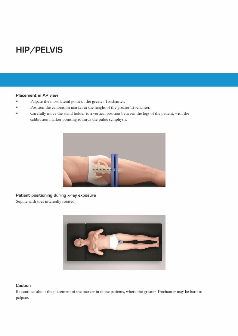
Placement in AP view• PalpatethemostlateralpointofthegreaterTrochanter.• PositionthecalibrationmarkerattheheightofthegreaterTrochanter.• Carefullymovethestandholdertoaverticalpositionbetweenthelegsofthepatient,withthe calibration marker pointing towards the pubic symphysis.
Patient positioning during x-ray exposureSupine with toes internally rotated
CautionBe cautious about the placement of the marker in obese patients, where the greater Trochanter may be hard to palpate.

KNEE AP
Placement in AP view• Position the calibration marker on the lateral
side of the knee, superior or inferior to the joint, and midway between the anterior and posterior surfaces of the knee.
• Verify that the calibration marker has not moved after the image has been acquired.
Patient positioning during x-ray exposureStanding

KNEE LAT
Placement in LAT view• Position the calibration marker on the
anterior side of the knee, either superior or inferior to patella, along the midline.
• Verify that the calibration marker has not moved after the image has been acquired.
Patient positioning during x-ray exposureStanding
SHOULDER/HUMERUS
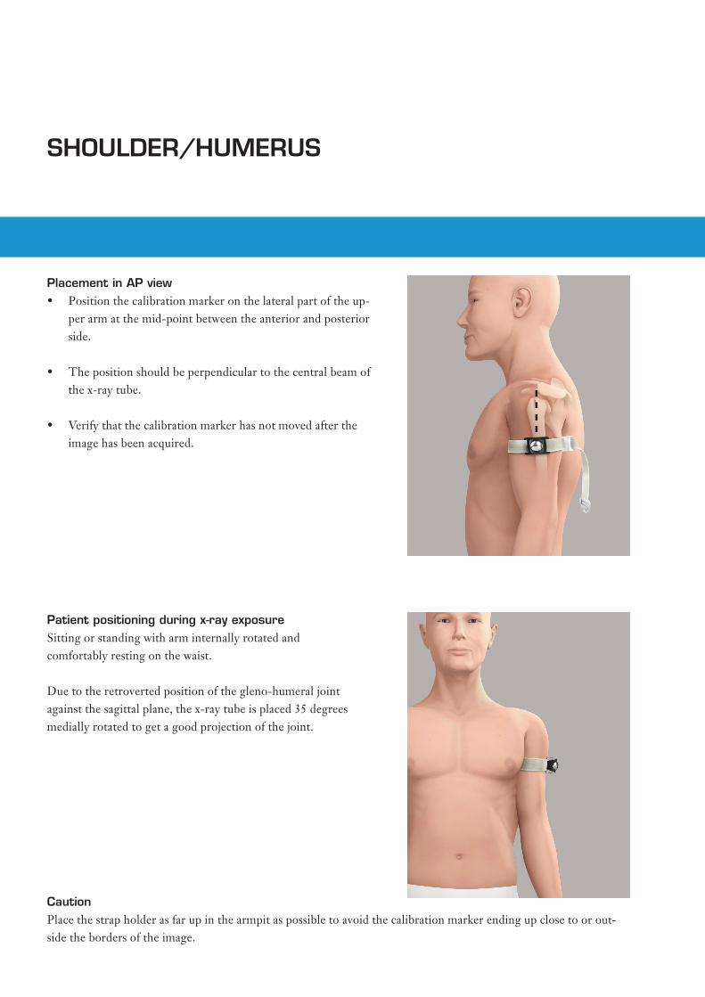
CautionPlace the strap holder as far up in the armpit as possible to avoid the calibration marker ending up close to or out-side the borders of the image.
Placement in AP view• Position the calibration marker on the lateral part of the up-
per arm at the mid-point between the anterior and posterior side.
• The position should be perpendicular to the central beam of the x-ray tube.
• Verify that the calibration marker has not moved after the image has been acquired.
Patient positioning during x-ray exposureSitting or standing with arm internally rotated and comfortably resting on the waist.
Due to the retroverted position of the gleno-humeral joint against the sagittal plane, the x-ray tube is placed 35 degrees medially rotated to get a good projection of the joint.

DO
C-U
VAH
-88P
FG8
2
010
Sec
tra Im
tec
AB
World HeadquartersSectra Imtec ABTeknikringen 20583 30 LinköpingSWEDENPhone: +46 13 23 52 00 E-mail: [email protected]
Ordering Information: Email: [email protected] Or contact you local sales rep.