e. aluminum automotive closure panel corrosion test … code 483-370-101 3300 general motors road...
TRANSCRIPT

FY 2005 Progress Report Automotive Lightweighting Materials
E. Aluminum Automotive Closure Panel Corrosion Test Program
Project Co-Chair: Tracie Piscopink-Jafolla General Motors Corporation Mail Code 483-370-101 3300 General Motors Road Milford, MI 48380-3726 (248) 676-7014; fax: (248) 685-5279; e-mail: [email protected]
Project Co-Chair: Francine Bovard Alcoa Technical Center 100 Technical Drive Alcoa Center, PA 15069 (724) 337-3249; fax: (724) 337-2044; e-mail: [email protected]
Technology Area Development Manager: Joseph A. Carpenter (202) 586-1022; fax: (202) 586-1600; e-mail: [email protected] Field Technical Manager: Philip S. Sklad (865) 574-5069; fax: (865) 576-4963; e-mail: [email protected]
Contractor: U.S. Automotive Materials Partnership Contract No.: FC26-020R22910
Objective • Develop a standardized cosmetic corrosion test for finished aluminum automotive body panels that
provides a good correlation with in-service testing and field performance.
Approach • Define test matrix.
• Specify and obtain materials.
• Specify phosphate and paint system.
• Pretreat and paint large reservoir of test specimens.
• Conduct laboratory testing, outdoor exposures, test-track exposures and in-service testing.
• Evaluate test data to determine which accelerated tests correlate with in-service testing.
• Conduct iterative laboratory testing to improve correlation between lab tests and on-vehicle exposures, and to determine reproducibility and repeatability of lab tests down-selected based upon initial data.
Accomplishments • Initial laboratory tests, test-track exposures and outdoor exposures completed.
• On-vehicle tests have been exposed for two years out of five planned.
• Initial evaluation of test-track exposures laboratory test samples completed
• Corrosion product analyses conducted for some laboratory tests.
• Analysis of initial laboratory test data completed and second iteration of lab tests defined
38

Automotive Lightweighting Materials FY 2005 Progress Report
Future Direction • Complete second round of laboratory tests
• Continue long-term in-service testing.
• Conduct corrosion product analyses for in-service tests.
Introduction The use of aluminum closure panels such as hoods, deck lids and lift-gates is increasing as the need to lower overall vehicle weight and thereby improve fuel economy increases. One of the key requirements for closure panel materials is a very high degree of corrosion resistance and excellent paint durability. Although aluminum closures have been used for many years, the general level of confidence and ability to predict corrosion lifetimes in service remains uncertain. Over the years, many laboratory corrosion test environments have been used to evaluate the performance of painted closure panels. Although the results of these tests can sometimes be useful for relative comparisons of alloy substrates and/or paint systems, the correlation of these lab test results with in-service performance has not been established in a systematic way. Extensive studies have been carried out in order to establish this correlation for finished cold-rolled and galvanized steel substrates [1] through cooperative efforts between the automotive companies and steel, pretreatment and paint suppliers. With the increased use of aluminum, it was recognized that a program was required to establish the correlation between lab test results and in-service performance for finished aluminum closure panels.
In response to this need, a group composed of representatives from the auto companies, the aluminum industry and associated suppliers was established in June of 2000 to formulate a program that would provide this correlation. The establishment of a standard test method for corrosion of aluminum closure panels through this effort will accelerate the adoption of lightweight aluminum materials to lower overall vehicle weight and reduce manufacturing costs by eliminating multiple test programs. A single corrosion test accepted throughout the industry could also be used to allow rapid selection and verification of alloy, pretreatment and paint performance. In this report, an outline of the test program, evaluation procedures
and discussion of the preliminary results from initial laboratory tests, outdoor tests, test-track exposures and on-vehicle exposures are presented.
Experimental Materials In 2001, the first step in the development of a new cosmetic corrosion test occurred with the establishment of a reservoir of painted panels. These panels would then be used in the subsequent evaluation of all test methods. As listed in Table 1, the substrate materials, metal finish and paint processing variables were selected to give a range of cosmetic corrosion performance. Several aluminum alloys used in the Unites States and in Europe, both current and historical, were included. Electro-zinc-coated steel and uncoated cold-rolled steel were included as reference materials. Two aluminum alloys were processed to simulate metal finishing in an automotive assembly plant body shop.
Table 1. Materials
Code Alloy Metal finish
Paint System
A AA6111-T4PD No Standard B AA6111-T4PD No Low F- C AA6111-T4PD No E-coat
Only D AA6111-T4PD Yes Standard E AA6016 No Standard F AA6022-T4E29 No Standard G AA2036 Yes Standard H EG 60 Steel No Standard I CRS No Standard
The materials were painted with a typical automotive paint system. This paint system included zinc phosphate pre-treatment, medium-build cathodic electrophoretic priming (e-coating), and spray painting with a primer surfacer and white basecoat - clear topcoat system for a total paint film thickness of approximately 100 μm. An additional set of 6111 panels was processed through the
39
FY 2005 Progress Report
phosphate pre-treatment with lower fluoride concentration (comparable to the fluoride level used for steel-only vehicles). Also, since qualification testing is often done on panels that are processed only through the electrophoretic primer (e-coat) step, another set of 6111 panels was processed only through the e-coat step, i.e., standard fluoride for Al but no basecoat or clear coat applied.
Panels were prepared for testing with two parallel scribes penetrating through the coatings to the substrate. The painted and scribed samples were then sent to laboratories for testing in a variety of environments, including laboratory, static outdoor exposure, proving-ground, and on-vehicle tests.
Evaluation Method The evaluation of scribe corrosion has traditionally been performed visually with a simple ruler by measuring creepage distance. While this simple technique of measuring creepage distance has provided some quantitative measure of corrosion severity, the one-dimensional interpretation (length only) of this manual technique provides only a partial quantification of the two-dimensional creepage phenomena. In the case of filiform corrosion found in aluminum substrates where creepage does not propagate uniformly along the scribe line as in steel substrate but rather forms thread-like, circuitous filament lines, this one-dimensional manual technique of measuring straight-line distance may incorrectly quantify corrosion.
Optical macro-imaging is a proven instrumentation technology that, when applied to the evaluation of two-dimensional surface defects, provides more reliable and accurate measurements of geometrical shapes than are obtainable with traditional human visual evaluation methods or one-dimensional extrapolative analysis of two-dimensional shapes. For this study, an optical imaging system developed by Atlas Material Testing Technology LLC was employed to quantitatively interpret the degree of filiform corrosion. The imaging system employs controlled illumination conditions (geometry and intensity), high-resolution digital image capture and advanced algorithm-based image and data analysis methodologies. The use of optical imaging techniques eliminates the influences of human
Automotive Lightweighting Materials
subjectivity by digitally capturing all sample images under the same enhanced illumination conditions and then subjecting them to a consistent image analysis administered by objective computer software [2-6].
For this study, four geometrical attributes were measured: area of corrosion, maximum creepage, minimum creepage, and average creepage. The area of corrosion was found to be the most representative and comprehensive measurement. Because the size of the panels and therefore the scribe lengths for the lab tests were different from the other tests, the corrosion area was normalized to the length of the scribe (i.e., area per length). The normalized corrosion areas for triplicate panels (2 scribes per panel) were then averaged and the results are reported as “normalized average area.”\
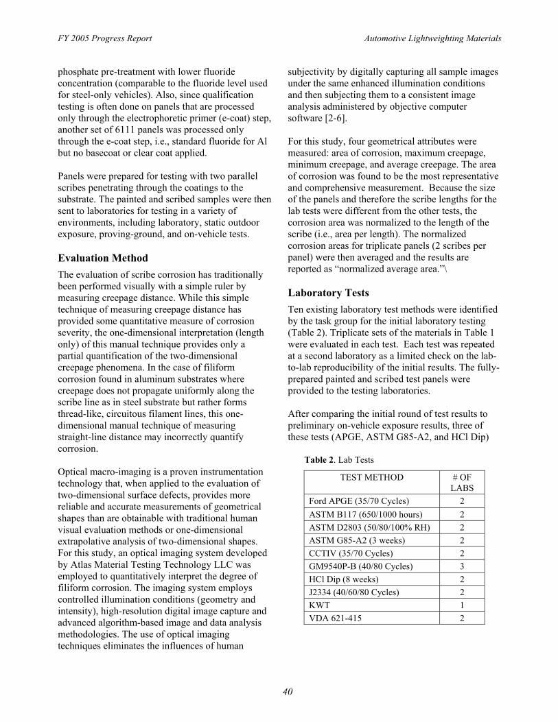
Laboratory Tests Ten existing laboratory test methods were identified by the task group for the initial laboratory testing (Table 2). Triplicate sets of the materials in Table 1 were evaluated in each test. Each test was repeated at a second laboratory as a limited check on the lab-to-lab reproducibility of the initial results. The fully-prepared painted and scribed test panels were provided to the testing laboratories.
After comparing the initial round of test results to preliminary on-vehicle exposure results, three of these tests (APGE, ASTM G85-A2, and HCl Dip)
Table 2. Lab Tests
TEST METHOD # OF LABS
Ford APGE (35/70 Cycles) 2 ASTM B117 (650/1000 hours) 2 ASTM D2803 (50/80/100% RH) 2 ASTM G85-A2 (3 weeks) 2 CCTIV (35/70 Cycles) 2 GM9540P-B (40/80 Cycles) 3 HCl Dip (8 weeks) 2 J2334 (40/60/80 Cycles) 2 KWT 1 VDA 621-415 2
40

Automotive Lightweighting Materials
were selected for further evaluation. Round-robin testing of these test methods is currently in progress. The duration of the tests is being varied in an attempt to further improve the correlation of these accelerated tests with the results from the on-vehicle exposures. Each test will be conducted at five laboratories to more thoroughly evaluate the repeatability and reproducibility of the test methods.
In-service (On-vehicle) Exposures It is critical when developing a laboratory-based test that test-to-field correlation be performed. In an effort to capture real-world data in developing this test it is necessary to expose these panels to severely corrosive environments that represent “worst case” real-world service environments. Suitable environments exist in the northeastern United States, southeastern coastal areas of the United States, and southeastern Canada. The five sites selected for this study were: 1.) Detroit, Michigan; 2.) Orlando, Florida; 3.) St. John’s, Newfoundland; 4.) Montreal, Quebec; and 5.) Ohio-New York Truck Route.
Two sets of 2” x 4” test panels are exposed on each vehicle (two vehicles per site). Each set of 24 (three each of eight material variables) are attached to a mounting panel (16” x 12”) using double-backed tape prior to mounting on vehicle. At the Detroit, St. Johns, and Montreal sites, one set is mounted on the hood of each vehicle (horizontal orientation) and one set on the right front door of each vehicle (vertical orientation). At the Florida and Ohio-New York sites, the panels are mounted beneath the trailer frame behind the front wheels (vertical orientation only). Each panel contains 2 diagonal scribe lines which are 2” long and 1” apart. The panels will be exposed for a total of 5 years of in-service exposure. Intermediate evaluations will be conducted when possible.
OEM Test-Track Exposures Proving-ground tests have historical background and are based on extensive test-to-field correlation studies on steel automotive body panels. The four proving grounds selected for this study were: 1.) GM – Milford, Michigan; 2.) Ford – Flagstaff, Arizona; 3.) DCX – Chelsea, Michigan; and 4.) ARL – Aberdeen, Maryland.
FY 2005 Progress Report
Each site exposed two sets of 24 test panels which are 2” x 4” with pre-cut edges. Each set of 24 (three each of eight material variables) will be attached to a mounting panel (16” x 12”) using double-backed tape prior to mounting on vehicle. One set will then be on the hood of each vehicle (horizontal orientation) and one set on the right front door of each vehicle (vertical location). Each panel contains two diagonal scribe lines which are 2” long and 1” apart. The panels were exposed for durations that prior testing indicates should be representative of ~10 years of field exposure.
Outdoor Exposures In addition to on-vehicle and OEM test-track exposures, static exposure for the products at the following test sites were elected for this study: 1.) ARL Exposure Site in Cape Canaveral, Florida and 2.) Alcoa Exposure Site in Pittsburgh, Pennsylvania.
Each test site exposed a set of 24 (three each of eight material variables) test panels which are 4” x 6” with pre-cut edges and a 5/16” diameter hole for mounting. Each panel contains two diagonal and parallel scribe lines which are 4” long and 1” apart. The panels will be exposure for two years of static outdoor exposure. The panels were manually sprayed with a 5% NaCl solution 2 times per week throughout the two-year exposure.
Corrosion Product Analysis In order to state categorically that any lab test correlates well with in-service corrosion performance, it is essential that the chemical nature of the corrosion products formed on lab tested materials match those on identically prepared materials exposed to in-service environments. Apart from the extent of corrosion found on painted coupons, the chemical composition of the corrosion products from laboratory and in-service exposure should be the similar if a good correlation exists. To initiate this comparison, the corrosion products from samples of AA6111 that had been exposed to some of the laboratory tests were analyzed using a variety of electron-optical techniques. This work was carried out in cooperation with the Surface Science group at the University of Western Ontario. A more detailed description of this work was presented at
41

FY 2005 Progress Report
the SAE 2004 Congress [7], so only a very brief description of this work is provided below.
Electron-optical techniques were selected to do this analysis because the amount of corrosion product on aluminum closure panels is very small, making more traditional analytical procedures impractical. In addition, the use of these methods allows not only for a measurement of the chemical species present, but also for an analysis of the distribution of these species in and around the corroded area on the panel. Work to date has shown that some lab tests, such as the SAE J2334, result in corrosion product formation where high localized concentrations of certain elements such as chloride are found at the periphery of the corrosion site, whereas in other tests such as the CCT IV, the distribution of chemical species is much more homogeneous throughout the corrosion product. It is anticipated that initial comparisons of corrosion products in lab tests and in-service environments will be carried out in late 2005 and early 2006.
Results and Discussion Panels from the test tracks, outdoor tests, preliminary on-vehicle exposures and initial lab tests have been analyzed. At this point only a very limited amount of service-relevant results from the on-vehicle exposures is available. From these preliminary on-vehicle results it is qualitatively apparent that the panels with metal finishing (D & G) have significantly more corrosion than the other substrates (Figure 1). The preliminary results for normalized average area from on-vehicle service relevant exposures are plotted in Figure 2. Based on these preliminary results, accelerated tests that also show a significant difference between the substrates with metal finishing (i.e., sanding) and those without metal finishing would appear to correlate better with the preliminary observations from on-vehicle testing. Many of the accelerated lab tests do not show a significant difference between the substrates with and without metal finishing. Of the laboratory test methods evaluated thus far in the program, the ASTM G85-A2 test and the HCl dip test appear to show a significant difference in corrosion performance between the substrates with metal finishing (i.e., sanding) and those without metal finishing as illustrated in Figures 3 and 4. Also, the
Automotive Lightweighting Materials
APGE test showed this difference for one test lab, but not the second test lab as illustrated in Figure 5.
Likewise, test-track or proving-grounds tests that show a difference in performance related to metal finishing would qualitatively correlate better with the preliminary field test observations. One of the OEM test-track exposures appears to exhibit differences in the performance of substrates with and without metal finish that are consistent with the preliminary on-vehicle observations, but the other two OEM test tracks are not consistent with this difference as illustrated in Figure 6.
The actual appearance or morphology of the corrosion is also an important consideration. Ideally, the morphology of the corrosion generated by the accelerated laboratory test should mimic that observed in the on-vehicle exposures in Figure 1. Examples of the morphology observed from the three lab tests that quantitatively differentiated the corrosion performance based metal finish are shown in Figure 7. Of these, the APGE test appears to mimic the field tests better in that the corrosion is blister-like and localized. The HCl dip test and the ASTM G85-A2 test generated corrosion more uniformly along the entire scribe line.
Conclusions Correlation of accelerated tests with on-vehicle exposures is critical for this test development effort. Three accelerated tests that have shown signs of possible correlation with on-vehicle tests (APGE, HCl Dip and ASTM G85-A2) have been selected for further evaluation. Additionally, it was shown that only one of the three OEM test tracks correlated reasonably well with preliminary on-vehicle exposure results. The reproducibility of the tests is also an important consideration, which will require additional testing to evaluate. A few additional accelerated laboratory tests will also be considered in an effort to find a lab test with improved correlation to in-service vehicle testing and the correct morphology.
42

Automotive Lightweighting Materials FY 2005 Progress Report
Figure 1. Representative images of panels from the Detroit On-Vehicle Test after 1.5 years in-service exposure.
43

FY 2005 Progress Report Automotive Lightweighting Materials
1200
1000
800
600
400
200
0
On-Vehicle Exposures1.5 to 2 years
Detroit OV1-V Detroit-OV1-H Detroit-OV2-V Detroit-OV2-H OH/NY-OV-V
Aluminum Steel
H
V V
H
A B D E F G H I
Panel Code
Figure 2. Normalized average area for preliminary on-vehicle service-relevant exposures.
44

Automotive Lightweighting Materials FY 2005 Progress Report
ASTM G85-A2 (Dry Bottom)3500
3000
2500
2000
1500
1000
500
0
G85-1-3wks (dry bottom)
G85-2-3wks (dry bottom)
Aluminum Steel
A B C D E F G H I
Panel Code
Figure 3. Normalized average area of corrosion for ASTM G85-A2.
45

FY 2005 Progress Report Automotive Lightweighting Materials
1200
1000
800
600
400
200
0
HCl Dip Test
HCl-Dip-1-8wks
HCl-Dip-2-8wks
Aluminum Steel
A B C D E F G H I
Panel Code
Figure 4. Normalized average area of corrosion for HCl Dip Test.
46

Automotive Lightweighting Materials FY 2005 Progress Report
1200
1000
800
600
400
200
0
APGE 70 Cycles
APGE-1-70 Cycles APGE-2-70cycles
Aluminum Steel
A B C D E F G H I
Panel Code
Figure 5. Normalized average area of corrosion for APGE.
47

FY 2005 Progress Report Automotive Lightweighting Materials
1200
1000
800
600
400
200
0 A B
OEM Test Tracks
OEM1-TT-H OEM1-TT-V OEM2-TT-H OEM2-TT-V OEM3-TT-H OEM3-TT-V
Aluminum Steel
H
V V
H
D E F G H I
Panel Code
Figure 6. Normalized average area of corrosion for OEM test tracks
48

Automotive Lightweighting Materials FY 2005 Progress Report
APGE 70 Cycles
HCl Dip 8 weeks
ASTM G85-A2 3 weeks
Figure 7. Representative images from APGE, HCL Dip and ASTM G85-A2.
49

FY 2005 Progress Report
References 1. SAE J2334, “Cosmetic Corrosion Lab Test”,
Society of Automotive Engineers, Warrendale, PA, June 1998.
2. Lee F, Ryntz, R, Britz, D., “Analysis of Scratch Resistance Using Optical Imaging and Automatic Classification”, 4th International Coatings for Plastics Symposium, June 4-6 2001, Troy, MI
3. Lee, F., Pourdeyhimi B, and Adamsons, K, “Analysis of Coatings Appearance and Surface Defects Using Digital Image Capture/Processing/Analysis, The International Symposium on a Systems Approach to Service Life Prediction of Organic Coatings, Breckenridge, CO, Sep.14-19, 1997
4. Pourdeyhimi, B., and Lee, F. European Coatings Journal, 1995, 11, 804.
5. Wypych, G., Lee, F., Pourdeyhimi, B., Durability of Building and Construction Sealants, Ed. A. T. Wolf, RILEM, 2000.
Automotive Lightweighting Materials
6. Lee, F., Pourdeyhimi, B., and Martin, J., “Comparative Study of Standard Weathering Test Methods Using Image Analysis,” Durability 2000: Accelerated and Outdoor Weathering Testing, ASTM STP 1385, J.D. Evans and W.D. Ketola, Eds., American Society for Testing and Materials, West Conshohocken, PA, 2000.
7. Corrosion Product Analysis of Aluminum Closure Panels, S. Ramamurthy et al., SAE paper 05B-417, 2005
Presentations/Publications/Patents SAE 2002B-203 SAE 2003-01-1235 SAE 2005-01-0542
50