ict- 257626 acropolis date: 05/03/2013 - … (oai) is an open-source hardware/software development...
TRANSCRIPT
ICT- 257626 ACROPOLIS Date: 05/03/2013
ICT-ACROPOLIS Deliverable D5.2 1/43
Advanced coexistence technologies for radio optimisation in licensed and unlicensed spectrum
(ACROPOLIS)
Document Number D5.2
Report on the Analysis of OpenAirInterface and its Distribution in the Consortium
Contractual date of delivery to the CEC: 30/09/2012 Actual date of delivery to the CEC: 30/09/2012
Project Number and Acronym: 257626 – ACROPOLIS Editor: Raymond Knopp (EURECOM) Authors: Raymond Knopp (EURECOM)
Carina Schmidt-Knorreck (EURECOM) Dominique Nussbaum (EURECOM) Navid Nikaein (EURECOM) Bassem Zayen (EURECOM)
Participants: EURECOM
Workpackage: WP5 Security: Public (PU) Nature: Report Version: 1.0
Total Number of Pages: 44
ICT- 257626 ACROPOLIS Date: 05/03/2013
ICT-ACROPOLIS Deliverable D5.2 2/43
Abstract: This document provides an overview of the current status of OpenAirInterface.org both in terms of its hardware and software elements. Details on the newest hardware platform, ExpressMIMO2, developed for experimentation in cognitive wireless networking are provided. The LTE SDR implementation, OpenAir4G, is described in addition to a new 802.11 SDR implementation, OpenAirITS. Information on OAI Training activities undertaken in 2012 and those planned for early 2013 are provided.
Keywords: Hardware/Software Platforms, OpenAirInterface, Platform training
Document Revision History
Version Date Author Summary of main changes
0.1 01.09.2012 EURECOM Initial structure of the document
0.2 29.09.2012 EURECOM editing
1.0 30.09..2012 EURECOM Delivery to EC
ICT- 257626 ACROPOLIS Date: 05/03/2013
ICT-ACROPOLIS Deliverable D5.2 3/43
Table of Contents
1. Introduction ................................................................................................... 6 1.1 Role of WP 5 in Acropolis ............................................................................... 7 1.2 Purpose of D5.2 ........................................................................................... 7
2. Evolution of OAI Hardware Platforms in 2012-2013 –ExpressMIMO2 ............ 9 2.1 ExpressMIMO2 motherboard characteristics ..................................................... 9 2.2 Examples of ExpressMIMO2 RF performance .................................................. 11 2.3 Multi-band RF front-end characteristics ......................................................... 13
3. SDR Architecture Exploration on ExpressMIMO ............................................ 17 3.1 Brief Overview of ExpressMIMO .................................................................... 17
3.1.1 Control ............................................................................................... 18 3.1.1.1 Choice of the Operating System for LEON3 ........................................ 19
3.1.2 Baseband Design and Emulation ............................................................ 19 3.1.2.1 Generic DSP Shell .......................................................................... 19 3.1.2.2 Overview of the different DSP engines .............................................. 22 3.1.2.3 Processing Times ........................................................................... 24 3.1.2.4 Receiver Emulation using the Library for ExpressMIMO baseband (libembb) ................................................................................................. 25
3.1.3 Development Methodology .................................................................... 25 3.2 ASIP Implementation of FEP ........................................................................ 26
3.2.1 Motivation ........................................................................................... 26 3.2.2 Conclusions from the study ................................................................... 27
4. Softmodems and protocol stack implementations ........................................ 28 4.1 Overview of OAI LTE Implementation (OpenAir4G) ......................................... 28
4.1.1 OpenAir4G Protocol Stack...................................................................... 31 4.1.1.1 NAS .............................................................................................. 32 4.1.1.2 RRC .............................................................................................. 32 4.1.1.3 MAC ............................................................................................. 32 4.1.1.4 PDCP ............................................................................................ 33 4.1.1.5 RLC .............................................................................................. 33
4.2 Specific Extensions of OpenAir4G in the context of Acropolis ............................ 33 4.2.1 Support for Carrier Aggregation and distributed interference management protocols ..................................................................................................... 34
4.2.1.1 Overview of Carrier Aggregation in Release-10 LTE ............................ 34 4.2.1.2 Overview of OAI extensions for Carrier Aggregation ........................... 35
4.2.2 Advanced Signal Processing in Support of Cognitive Overlay Networks ........ 37 4.3 OpenAirITS and DAB ................................................................................... 37
4.3.1 Intel x86-based OpenAirITS implementation ............................................ 38 5. Training and Teaching Activities on OAI ....................................................... 39
5.1 OAI Training activities in 2012 ..................................................................... 39 5.1.1 OAI Labs ............................................................................................. 39
5.2 Envisaged OAI Training activities in 2013 ...................................................... 40 6. Conclusion .................................................................................................... 41 7. References ................................................................................................... 42
ICT- 257626 ACROPOLIS Date: 05/03/2013
ICT-ACROPOLIS Deliverable D5.2 4/43
List of Tables
Table 1: Frequency Bands and Duplexing (below 4GHz) ........................................... 14 Table 2: ExpressMIMO Cycle Counts (T should be read in clock cycles) ...................... 24 Table 3: Physical Channel Support in OpenAirInterface.org (3GPP 36-211) ................. 29 Table 4: Coding and Multiplexing (36.212) ............................................................. 30 Table 5: Physical Layer Procedures (3GPP 36-213) .................................................. 31
ICT- 257626 ACROPOLIS Date: 05/03/2013
ICT-ACROPOLIS Deliverable D5.2 5/43
List of Figures
Figure 1: ExpressMIMO2 Motherboard ................................................................... 10 Figure 2: ExpressMIMO2 Embedded System ........................................................... 11 Figure 3: RX Constellation, LTE 5MHz 35dB SNR ..................................................... 12 Figure 4: RX Spectrum (LTE 5 MHz, 35 dB SNR) ..................................................... 12 Figure 5: ACLR at the TX output of ExpressMIMO2, at 750 MHz ................................ 13 Figure 6: Constellation at the TX output of ExpressMIMO2, at 750 MHz ...................... 13 Figure 7: External RF/Antenna modules for ExpressMIMO2 (one of 4) ........................ 14 Figure 8 : ACLR of RF FE @ 750 MHz, for 16 dBm .................................................... 15 Figure 9: ACLR of RF FE @ 2600 MHz, for 14 dBm ................................................... 16 Figure 10: ExpressMIMO Baseband Engine ............................................................. 18 Figure 11: OAI standardized IP Shell ..................................................................... 21 Figure 12: Illustration of the Basic (De)Interleaver Functionality ............................... 23 Figure 13: libembb Processing Flow ....................................................................... 25 Figure 14 OpenAir4G protocol stack ....................................................................... 32 Figure 15: Carrier Aggregation Protocol Replication at eNB ....................................... 35 Figure 16: PHY replication for aggregated CCs ........................................................ 35 Figure 17: Cognitive Overlay Scenario ................................................................... 37 Figure 18: Integration of OpenAirITS with mac80211 .............................................. 38
ICT- 257626 ACROPOLIS Date: 05/03/2013
ICT-ACROPOLIS Deliverable D5.2 6/43
1. Introduction
OpenAirInterface.org (OAI) is an open-source hardware/software development platform and open-forum for innovation in the area of digital radio communications. It was created by the Mobile Communications Department at EURECOM based on its experience in publicly-funded R&D carried out in the context of collaborative research projects (French national and European Framework programs). Its main objective is provide such collaborative projects with an open-architecture platform, including both the constituent hardware and software elements, which can be enhanced by the scientific community at large.
The initiative provides tools for experimentation with real-time radio resources and scalable simulation/emulation environments for wireless communications. At the same time it strives to demonstrate innovation in high-performance embedded computing architectures based on open-source design tools.
The development made available (both hardware and software) should not be considered to constitute a complete system solution, in the sense that an operator could download the software, purchase the hardware, and subsequently deploy a large-scale network. It can be used to deploy reduced-scale test networks in order to demonstrate innovative ideas in a realistic radio propagation and application scenario.
Thanks to the open-development policy, it is hoped that some parts may influence the evolution of industrial wireless stacndards such as LTE. As such, it currently supports a subset of the 3GPP LTE specifications (the majority of Release 8 and up to some aspects of Release 10) as well as the 802.11p WIFI standard for vehicular communications.
ICT- 257626 ACROPOLIS Date: 05/03/2013
ICT-ACROPOLIS Deliverable D5.2 7/43
1.1 Role of WP 5 in Acropolis The objective of WP 5 is to analyze various existing hardware and software platforms that are available to the ACROPOLIS consortium and can be used for R&D purposes. The work began by a critical analysis of different platforms (so that it heavily interacts with WP 7) and described how best-practices are shared between partners to accelerate work in this area. The latter was described in D5.1. In order to integrate and to enhance the available knowledge and expertise of the participating partners, a network for exchanging software modules and hardware experiences has been set up. Furthermore, several training activities on the available platforms have been organized and more are planned for 2013, so as to increase the awareness of the participating partners on the available platforms and to stimulate coordination among them. One central activity in WP5 is also the analysis and valorisation of the European OAI platform, which will be made available for consortium members by EURECOM. The software tools are provided under open-source policy and the newest hardware elements will be offered to consortium members along with support services. To this end, a significant effort has been made in 2011-2012 with respect to the design of the most recent hardware elements (ExpressMIMO2) of OAI platforms to provide a low-cost solution for experimentation in cognitive networking. The existing earlier hardware elements, ExpressMIMO, were deemed too costly by most partners for networking experimentation and thus serve primarily for the purpose of software-defined radio (SDR) architecture exploration studies in WP7, such as those described in section 3. Moreover, the low-end and low-cost CBMIMO1 platform used in many past projects lacks sufficient RF agility to be used for cognitive networking and suffers for various reasons from the age of its constituent RF components and bus interface. In the context of the Network of Excellence WP5 aims at enhancing the existing OAI implementation to provide more support for distributed interference management and cognitive wireless networking. It interacts with WP 8 and WP 9 and with ongoing FP7 projects further developing this technology by federating techniques emanating from these sources around OAI. To this end, the fact that OAI is primarily LTE-oriented allows for demonstrating the impact that research in cognitive radio has mainstream wireless technology. This is primarily of interest in the context of distributed network management for small cells or opportunistic spectrum-access in remote areas. Another potential application are for the ideas explored using this technology in the context of the Network of Excellence is for rapidly-deployable networks in support of public safety. The latter has become of paramount importance due to the fact that since the onset of the Network, industry and government agencies have adopted LTE radio-access for the future public-safety radio networks around the globe. These target scenarios are explained in more detail in D5.1.
1.2 Purpose of D5.2 First and foremost, this document is intended to provide an overview of the current status of OAI both in terms of its hardware and software elements. Section 2 provides an overview

ICT- 257626 ACROPOLIS Date: 05/03/2013
ICT-ACROPOLIS Deliverable D5.2 8/43
of the newest hardware platform, ExpressMIMO2, developed for experimentation in cognitive wireless networking. Architecture exploration studies using ExpressMIMO are reviewed in Section 3. We describe the current status of the LTE SDR implementations, OpenAir4G, in Section 4 in addition to a new 802.11 SDR implementation which is integrated with the new mac80211 development provided with up-to-date Linux distributions. OAI Training activities undertaken in 2012 and those planned for early 2013 are described in Section 5. The document ends with a concluding section.
ICT- 257626 ACROPOLIS Date: 05/03/2013
ICT-ACROPOLIS Deliverable D5.2 9/43
2. Evolution of OAI Hardware Platforms in 2012-2013 –ExpressMIMO2 The newest platform which can target OAI software, whose latest version is described in Section 4, was given the code name ExpressMIMO2 since it follows its predecessor ExpressMIMO. The key target for ExpressMIMO2 was to reduce its cost so as to make it accessible for other laboratories wanting to experiment with OAI using a reasonable number of nodes (i.e. normally greater than 2). The board was designed to allow for stand-alone operation at low-power levels (maximum 0 dBm transmit power per channel) simply by connecting an antenna to the board. The chosen RF technology covers a very large part of the available RF spectrum (250 MHz-3.8 GHz) with channels up to 20 MHz bandwidth. ExpressMIMO2 is designed to be used with off-the-shelf PCs running standard Linux distributions and potentially a real-time extension (RTAI/Xenomai or PREMPT-RT) in order to make use of open-source development tools and open-source networking tool suites and applications, both stable and experimental. EURECOM has successfully tested the board with regular laptops through a readily-available (and cheap) conversion cable in order to connect through the ExpressCard slot which also uses PCIexpress technology. Today OAI supports RTAI but the other options may become available for ExpressMIMO2, as a function of partners‘ and projects’ interest. The PCIexpress bus interface allows existing drivers from its predecessors (CBMIMO1 and ExpressMIMO) to be used as is. Similarly the OAI OCTAVE interfaces for non-real time experiments can also be used with changes only related to configuration of the new RF components. The cost of the board is approximately 1500 euros, depending on quantities ordered with the company fabricating the board, and could actually be less in time. EURECOM will provide information to partners in the Network of Excellence wishing to acquire such equipment.
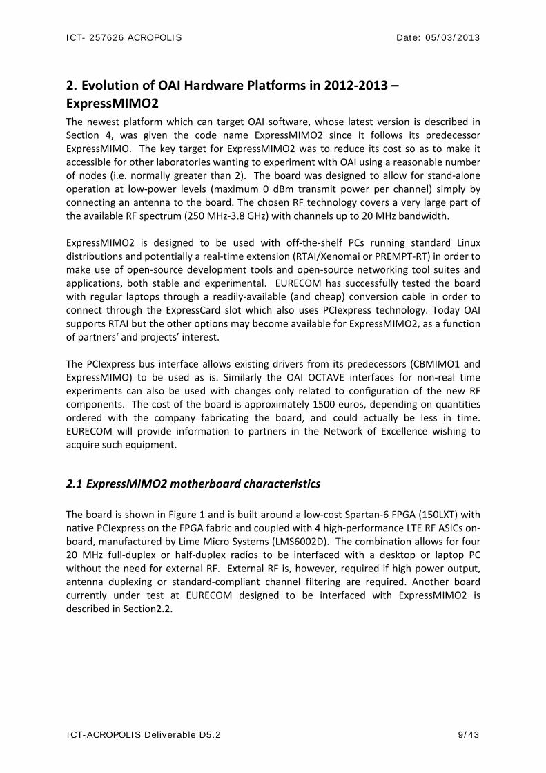
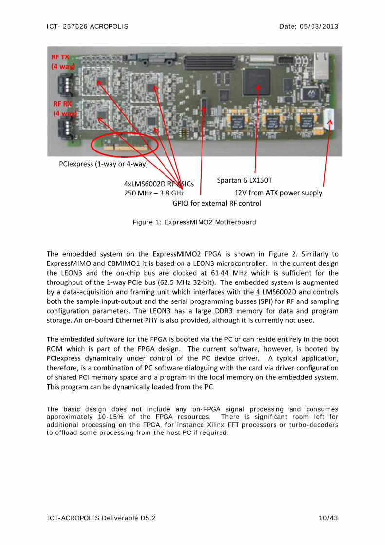
2.1 ExpressMIMO2 motherboard characteristics The board is shown in Figure 1 and is built around a low-cost Spartan-6 FPGA (150LXT) with native PCIexpress on the FPGA fabric and coupled with 4 high-performance LTE RF ASICs on-board, manufactured by Lime Micro Systems (LMS6002D). The combination allows for four 20 MHz full-duplex or half-duplex radios to be interfaced with a desktop or laptop PC without the need for external RF. External RF is, however, required if high power output, antenna duplexing or standard-compliant channel filtering are required. Another board currently under test at EURECOM designed to be interfaced with ExpressMIMO2 is described in Section2.2.
ICT- 257626 ACROPOLIS Date: 05/03/2013
ICT-ACROPOLIS Deliverable D5.2 10/43
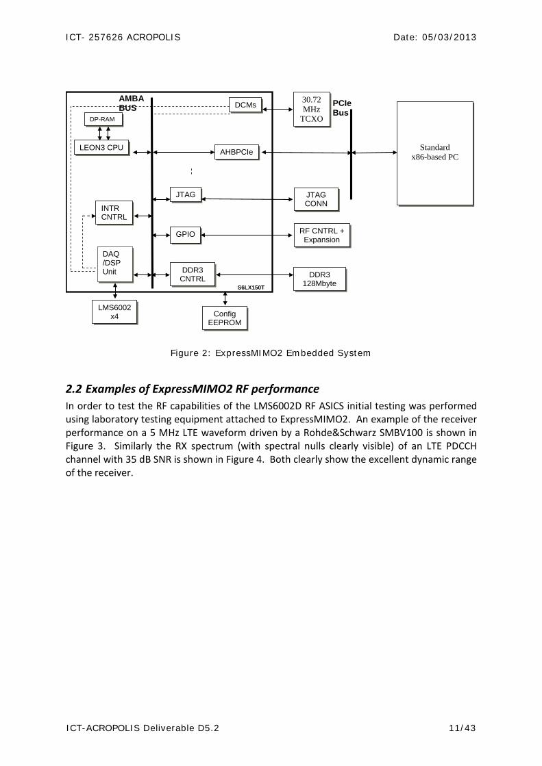
The embedded system on the ExpressMIMO2 FPGA is shown in Figure 2. Similarly to ExpressMIMO and CBMIMO1 it is based on a LEON3 microcontroller. In the current design the LEON3 and the on-chip bus are clocked at 61.44 MHz which is sufficient for the throughput of the 1-way PCIe bus (62.5 MHz 32-bit). The embedded system is augmented by a data-acquisition and framing unit which interfaces with the 4 LMS6002D and controls both the sample input-output and the serial programming busses (SPI) for RF and sampling configuration parameters. The LEON3 has a large DDR3 memory for data and program storage. An on-board Ethernet PHY is also provided, although it is currently not used. The embedded software for the FPGA is booted via the PC or can reside entirely in the boot ROM which is part of the FPGA design. The current software, however, is booted by PCIexpress dynamically under control of the PC device driver. A typical application, therefore, is a combination of PC software dialoguing with the card via driver configuration of shared PCI memory space and a program in the local memory on the embedded system. This program can be dynamically loaded from the PC.
The basic design does not include any on-FPGA signal processing and consumes approximately 10-15% of the FPGA resources. There is significant room left for additional processing on the FPGA, for instance Xilinx FFT processors or turbo-decoders to offload some processing from the host PC if required.
PCIexpress (1-way or 4-way)
4xLMS6002D RF ASICs 250 MHz – 3.8 GHz
Spartan 6 LX150T
GPIO for external RF control
RF TX (4 way)
12V from ATX power supply
RF RX (4 way)
Figure 1: ExpressMIMO2 Motherboard
ICT- 257626 ACROPOLIS Date: 05/03/2013
ICT-ACROPOLIS Deliverable D5.2 11/43
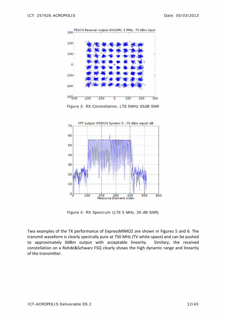
2.2 Examples of ExpressMIMO2 RF performance In order to test the RF capabilities of the LMS6002D RF ASICS initial testing was performed using laboratory testing equipment attached to ExpressMIMO2. An example of the receiver performance on a 5 MHz LTE waveform driven by a Rohde&Schwarz SMBV100 is shown in Figure 3. Similarly the RX spectrum (with spectral nulls clearly visible) of an LTE PDCCH channel with 35 dB SNR is shown in Figure 4. Both clearly show the excellent dynamic range of the receiver.
LEON3 CPU
DDR3 CNTRL
GPIO
AHBPCIe
DAQ /DSP Unit
DP-RAM
JTAG
INTR CNTRL
AMBA BUS
DDR3 128Mbyte
RF CNTRL + Expansion
JTAG CONN
Config EEPROM
DCMs 30.72 MHz
TCXO
LMS6002 x4
PCIe Bus
S6LX150T
Standard x86-based PC
Figure 2: ExpressMIMO2 Embedded System
ICT- 257626 ACROPOLIS Date: 05/03/2013
ICT-ACROPOLIS Deliverable D5.2 12/43
Figure 3: RX Constellation, LTE 5MHz 35dB SNR
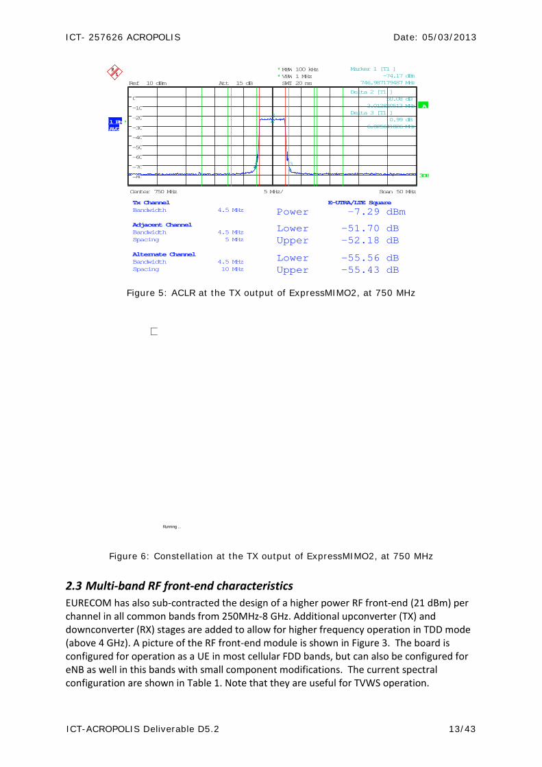
Two examples of the TX performance of ExpressMIMO2 are shown in Figures 5 and 6. The transmit waveform is clearly spectrally pure at 750 MHz (TV white-space) and can be pushed to approximately 0dBm output with acceptable linearity. Similary, the received constellation on a Rohde&Schwarz FSQ clearly shows the high dynamic range and linearity of the transmitter.
Figure 4: RX Spectrum (LTE 5 MHz, 35 dB SNR)
ICT- 257626 ACROPOLIS Date: 05/03/2013
ICT-ACROPOLIS Deliverable D5.2 13/43
Ref 10 dBm Att 15 dB
AVG
A
1 RM*
Center 750 MHz Span 50 MHz5 MHz/
**
3DB
RBW 100 kHzVBW 1 MHzSWT 20 ms
-80
-70
-60
-50
-40
-30
-20
-10
0
Tx Channel E-UTRA/LTE Square Bandwidth 4.5 MHz Power -7.29 dBm Adjacent Channel Bandwidth 4.5 MHz Lower -51.70 dB Spacing 5 MHz Upper -52.18 dB Alternate Channel Bandwidth 4.5 MHz Lower -55.56 dB Spacing 10 MHz Upper -55.43 dB
1
Marker 1 [T1 ] -74.17 dBm 746.987179487 MHz
2
Delta 2 [T1 ] 50.08 dB 3.012820513 MHz
3
Delta 3 [T1 ] 0.99 dB 6.025641026 MHz
Figure 5: ACLR at the TX output of ExpressMIMO2, at 750 MHz
Running ...
Figure 6: Constellation at the TX output of ExpressMIMO2, at 750 MHz
2.3 Multi-band RF front-end characteristics EURECOM has also sub-contracted the design of a higher power RF front-end (21 dBm) per channel in all common bands from 250MHz-8 GHz. Additional upconverter (TX) and downconverter (RX) stages are added to allow for higher frequency operation in TDD mode (above 4 GHz). A picture of the RF front-end module is shown in Figure 3. The board is configured for operation as a UE in most cellular FDD bands, but can also be configured for eNB as well in this bands with small component modifications. The current spectral configuration are shown in Table 1. Note that they are useful for TVWS operation.

ICT- 257626 ACROPOLIS Date: 05/03/2013
ICT-ACROPOLIS Deliverable D5.2 14/43
Band Duplex
1 TVWS (400-790MHz) TDD
2 DD (790- 862 MHz) TDD
3 DD (790- 862 MHz) FDD4 1900 Mhz TDD5 2,4 Ghz TDD6 2,6 GHz FDD7 2,6 GHz TDD8 3,5 Ghz TDD9 5-6 GHz TDD
10 3,5 GHZ FDD
Table 1: Frequency Bands and Duplexing (below 4GHz)
Antenna connector (SMA)
RF Front End board
LO board
Figure 7: External RF/Antenna modules for ExpressMIMO2 (one of 4)
ICT- 257626 ACROPOLIS Date: 05/03/2013
ICT-ACROPOLIS Deliverable D5.2 15/43
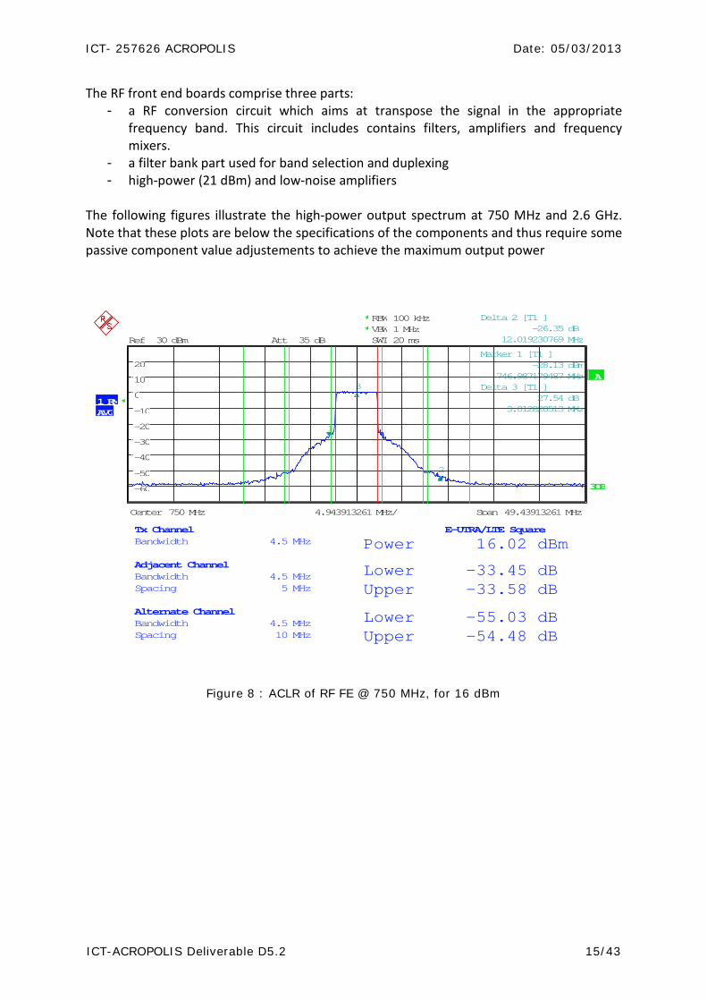
The RF front end boards comprise three parts: - a RF conversion circuit which aims at transpose the signal in the appropriate
frequency band. This circuit includes contains filters, amplifiers and frequency mixers.
- a filter bank part used for band selection and duplexing - high-power (21 dBm) and low-noise amplifiers
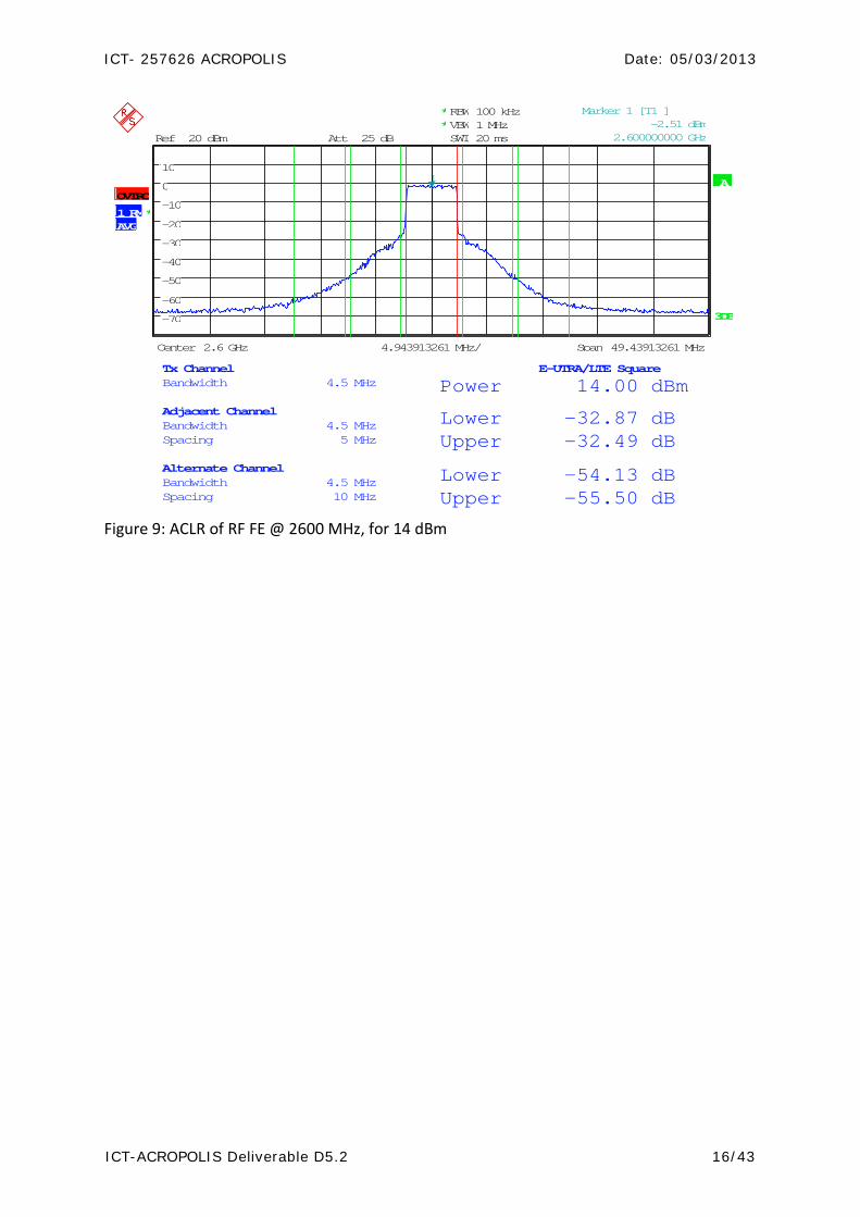
The following figures illustrate the high-power output spectrum at 750 MHz and 2.6 GHz. Note that these plots are below the specifications of the components and thus require some passive component value adjustements to achieve the maximum output power
Ref 30 dBm Att 35 dB
A
AVG
*
1 RM
3DB
RBW 100 kHzVBW 1 MHzSWT 20 ms*
*
Center 750 MHz Span 49.43913261 MHz4.943913261 MHz/
-60
-50
-40
-30
-20
-10
0
10
20
Tx Channel E-UTRA/LTE Square Bandwidth 4.5 MHz Power 16.02 dBm Adjacent Channel Bandwidth 4.5 MHz Lower -33.45 dB Spacing 5 MHz Upper -33.58 dB Alternate Channel Bandwidth 4.5 MHz Lower -55.03 dB Spacing 10 MHz Upper -54.48 dB
1
Marker 1 [T1 ] -28.13 dBm 746.987179487 MHz
2
Delta 2 [T1 ] -26.35 dB 12.019230769 MHz
3 Delta 3 [T1 ] 27.54 dB 3.012820513 MHz
Figure 8 : ACLR of RF FE @ 750 MHz, for 16 dBm
ICT- 257626 ACROPOLIS Date: 05/03/2013
ICT-ACROPOLIS Deliverable D5.2 16/43
A
3DB
RBW 100 kHz
SWT 20 ms
**
*1 RMAVG
VBW 1 MHz
OVTRC
Ref 20 dBm Att 25 dB
Center 2.6 GHz Span 49.43913261 MHz4.943913261 MHz/
-70
-60
-50
-40
-30
-20
-10
0
10
Tx Channel E-UTRA/LTE Square Bandwidth 4.5 MHz Power 14.00 dBm Adjacent Channel Bandwidth 4.5 MHz Lower -32.87 dB Spacing 5 MHz Upper -32.49 dB Alternate Channel Bandwidth 4.5 MHz Lower -54.13 dB Spacing 10 MHz Upper -55.50 dB
1
Marker 1 [T1 ] -2.51 dBm 2.600000000 GHz
Figure 9: ACLR of RF FE @ 2600 MHz, for 14 dBm
ICT- 257626 ACROPOLIS Date: 05/03/2013
ICT-ACROPOLIS Deliverable D5.2 17/43
3. SDR Architecture Exploration on ExpressMIMO
3.1 Brief Overview of ExpressMIMO The OpenAirInterface ExpressMIMO platform [1] was developed jointly by Eurecom and Télécom ParisTech. Its hardware potentially supports a wide range of different standards like GSM, UMTS, 802.11, DAB, LTE as well as their multimodal processing and Time / Frequency Division Duplex (TDD / FDD) modes. It should be noted that to-date the only considered air interfaces for which a subset of the air-interface procedures have been implemented are LTE, 802.11p and DAB. The platform is used primarily for architecture exploration in SDR studies. The platform is capable to process up to eight different channels simultaneously (four in reception, four in transmission) by reusing the same HW resources. As each channel may support a different wireless communication standard, the main design challenge is the synchronization of these resources by providing a maximum accuracy and by meeting all the real-time requirements. ExpressMIMO is used for experimental purposes only. Therefore the chosen target technology are FPGAs which come with a reduced design time, higher runtime flexibility, simple ease of use and lower costs for small quantities when compared to other solutions. Nevertheless ASICs are considered in a future version once the whole baseband design has been validated. In contrast to the previously presented solutions, the current design of the ExpressMIMO platform is split over two different FPGAs from Xilinx: (1) a Virtex 5 LX330 for the baseband processing and (2) a Virtex 5 LX110T for interfacing and control as shown in Figure 1. To simplify testing on the platform, the two FPGAs can run stand-alone if required. Another difference is that the baseband processing which is responsible for the signal processing of the transceiver is split over different DSP engines. The underlying hardware architecture further allows to process four receive and four transmit channels in parallel by using the same resources. The interface and control FPGA transfers the signal coming from / going to the MAC layer and contains the main CPU (SPARC LEON3 processor) being responsible for the main control flow of the system. The two FPGAs are connected via an AMBA / AVCI DSP bridge while the different DSPs on the baseband side are connected via an AVCI crossbar. As only seven DSPs plus the VCI RAM and the main CPU are connected with each other, the performance of this crossbar is sufficient for the design of the ExpressMIMO platform. The available memory space is distributed in a non-uniform way. Each DSP engine has its own memory space that is also mapped onto a global memory map. This global map is provided to the main CPU and to the DSPs and is consulted in case of DMA transfers between the DSPs or between the two FPGAs. For internal processing, the DSPs apply a local addressing scheme. In addition, an external DDR memory is available for mass storage on the baseband side and a DDR2 memory (size 16 MByte) contains the LEON3 program code and can be used for mass storage on the control side. Currently the whole design is running at a frequency of 100 MHz but the target is to increase this frequency to the maximum possible one of the main CPU (133 MHz) in the future. It is

ICT- 257626 ACROPOLIS Date: 05/03/2013
ICT-ACROPOLIS Deliverable D5.2 18/43
now likely that the entire embedded system will be ported to the new Xilinx ZYNC technology which will allow for much higher processing speeds.
3.1.1 Control The interface and control FPGA connects the ExpressMIMO platform with the external host PC by a JTAG and a PCIexpress connection (8-way when connected to a desktop PC, 1-way when connected to a laptop). The FPGA is further connected to a DDR2 memory available for mass storage of samples. Main component on the FPGA is the 32 bit SPARC LEON3 processor from Gaisler Aeroflex [2] that serves as main CPU for the baseband processing. In the future it is considered to replace it by a multiprocessor solution. An interesting candidate is the Xilinx Zynq [3] which includes an ARM Cortex A9. In contrast to LEON3 running at a maximum possible frequency of 133 MHz, Xilinx Zynq can be processed up to 800 MHz. Currently, all DSPs are controlled by the LEON3 processor who can program them by writing into or reading from the memory-mapped control registers and the memory-mapped local memories inside the DSPs. Data transfers between DSPs and from / to LEON3 can be established by either writing directly at corresponding global memory addresses or by DMA transfers. Observed programming latencies are related to the bridge connecting the two FPGAs. To minimize these latencies, it is planned to investigate in the effects of a distributed control flow on the platform. From the software point of view, the platform includes three different kinds of possible execution nodes: (1) the main CPU LEON3, (2) the microcontroller (UC) that can be included in each of the DSPs and (3) the DSPs itself. It is obvious that when splitting the control flow the design of the C application code running on LEON3 will become more challenging. But on the other side a distributed control flow will result in a more efficient transceiver processing, especially when executing multiple standards in parallel.
Figure 10: ExpressMIMO Baseband Engine
ICT- 257626 ACROPOLIS Date: 05/03/2013
ICT-ACROPOLIS Deliverable D5.2 19/43
3.1.1.1 Choice of the Operating System for LEON3
The SPARC LEON3 processor is supported by various Operating Systems (OS) like eCos [4], RTEMS (Real-Time Executive for Multiprocessor Systems) and freeRTOS (free Real-Time Operating System) which are all free and VXWorks which is not free. The main similarity between them is that they all use function calls (or static links) instead of system calls to reduce their internal latencies. For single processor systems, all of them achieve a very good performance which would make them ideal candidates for the current version of the ExpressMIMO platform. However, a future version of ExpressMIMO will include a multiprocessor system. To avoid a time-consuming software redesign it is therefore recommended to choose a free OS with multiprocessor support. A disadvantage of RTEMS is that it needs to run one instance of the OS per processor in the system. FreeRTOS has no multiprocessor support at all and the eCos multiprocessor support is still limited [4]. Therefore we decided to opt for MutekH ([5],[6]) which was originally designed to support multiprocessor heterogeneity of modern platforms. In contrast to the mentioned OS, MutekH provides a shared memory multiprocessors support and has been designed with strong multiprocessor support in mind. It further provides optimized function calls by using an appropriate set of inline functions. This reduces the latency of calls to the kernel which are frequent in parallel applications that are split in multiple threads to take advantages of several processors. For SPARC processors, unlike other kernels, MutekH uses the flat function call convention. This improves the interrupt latency and makes the function call time far more deterministic. Usually, SPARC comes with 32 general purpose registers that are always visible by the program. 24 of them are organized in a register window that is split over three different groups of eight registers. They are stated as out , l ocal and i n. The visible window per time instance is determined by the so-called Current Window Pointer. Using save and r est or e instructions that can be found at the beginning and at the end of each function, this pointer is moving. The register windows are overlapping, so the out registers are renamed when save is called and become the in registers. In addition to that, the Window Invalid Mask (WIM) register indicates if a window is invalid which results in copying the whole stack to the memory. All the mentioned processing operations sometimes result in a huge overhead which is very critical when processing standards with strong latency requirements. Therefore, MutekH has been optimized by a flat registers model where the compiler does not use save and restore instructions. The extra register windows which are not needed by the regular code can then be used to implement really fast interrupts context switching for free. All of these improvements reduce the latency significantly and make the ExpressMIMO platform also suitable for the processing of standards with short data sets. For multimodal processing, MutekH supports POSIX threads so that different transceivers can be executed on LEON3 simultaneously.
3.1.2 Baseband Design and Emulation
3.1.2.1 Generic DSP Shell
The architecture of the different DSP engines is based on a standardized DSP Shell shown in Figure 2 which is composed of
ICT- 257626 ACROPOLIS Date: 05/03/2013
ICT-ACROPOLIS Deliverable D5.2 20/43
• a Control Sub-System (CSS): The CSS is common to all DSP engines and is specialized through parameters. It optionally contains a local 8 bit UC (6502) and a 64 bit DMA engine as well as a set of control and status registers plus several arbiters and FIFOs for input-output requests and responses. Furthermore, the CSS acts as a gateway with the surrounding host system by using two 64 bit wide AVCI compliant interfaces. The first one is a slave (target) interface through which read and write requests to the internal control and status registers and to the Memory Sub-System (MSS) are received. The second one is a master (initiator) interface required by the DMA to perform data transfers between the MSS and external memory areas. In addition, a set of input and output interrupt lines is used for signaling and synchronization with the host system. The architecture of the UC inside the CSS is based on a Complex Instruction-Set Computer 15 (CISC) with 6 internal registers. Its address bus has a width of 16 bit and the reserved UC address space in the MSS has a size of 2 kB.
• Processing Unit (PU): The PU is custom defined and depends on the functionality of
the DSP. It is the main component of each DSP engine. The instructions required for the PU processing are received through the CSS and are stored in the control registers. So programming a DSP just means writing the parameters into the right registers.
• a Memory Sub-System (MSS): Like the PU, the MSS is custom defined and depends
on the functionality of the DSP. The MSS contains the address space for the program and data memory of the UC with a size of 2 kByte and the input-output data space with a variable memory size. To increase the maximum achievable frequency after place and route, the number of registers before and after the actual RAM inside the MSS is variable and may differ between the different DSP

ICT- 257626 ACROPOLIS Date: 05/03/2013
ICT-ACROPOLIS Deliverable D5.2 21/43
Figure 11: OAI standardized IP Shell
From the LEON3 point-of-view, all DSP engines are seen as a memory block mapped onto the global memory map. The size of each of these memories is set to 1 MByte and is aligned on a 1 MByte boundary. The UC and the DMA access memory spaces inside this memory but without having access to the global memory map. For the time being, the UC has not been integrated in the CSS yet. The current version of the receiver is thus orchestrated by a centralized control flow where the whole transceiver program is running on the main CPU. In the future a global control flow including the UC will be applied to reduce the interrupt rate and the communication overhead to the main CPU. Currently, the latter starts a DSP by writing a value in the so-called igost (Ip GO and STatus) register. Once the operation is finished an interrupt is raised. Each DSP unit has three different interrupt lines used for signaling to the host system when the scheduled task is finished: (1) UIRQ (UC), (2) DIRQ (DMA) and (3) IIRQ (PU). As an alternative, the main CPU can poll the ibsy flag of the igost register to get to know about the end of the PU processing. An important CSS feature is that one new command can already be prepared in the command registers. Once this happens the ipend flag is set to one to indicate that no more command can be prepared. The same
ICT- 257626 ACROPOLIS Date: 05/03/2013
ICT-ACROPOLIS Deliverable D5.2 22/43
rules apply as well when programming the DMA engine included in the CSS. In this case, the register dgost provides the main CPU with the status information.
3.1.2.2 Overview of the different DSP engines In general, the baseband design takes place between the RF front- and back-end and the decoded signal samples. It represents the implementation of the physical layer while MAC layer operations are performed on the host PC. As mentioned earlier the baseband processing of the Express-MIMO platform is structured in independent DSP engines which allow an easy upgrade to future standards. Other advantages include the effective use of spectrum, mobility, increased network capacity, maintenance of cost reduction and a faster development of new services. The DSPs have been designed in such a way that they support the most computationally intensive tasks in an efficient way. Prior to that, a detailed analysis of the commonalities between the standards has been carried out to make sure that the platform supports all current wireless communications standards by minimizing the resource consumption without the lack of high accuracy. The final designs are programmable, reconfigurable at runtime and can be processed in parallel which is of a significant importance for multimodal applications. In the context of different studies throughout the past years, seven different DSPs have been identified:
• Preprocessor (PP): The Preprocessor connects the external RF with the baseband system. The four A/D and four D/A converters (AD9832) provide 2x14 bit at 128 Ms/s in TX and 2x12 bit at 64 Ms/s in RX. Besides, the Preprocessor is used for basic signal processing functions including sample rate conversion, an NCO (Numerically Controlled Oscillator), I/Q imbalance correction as well as framing, (re)synchronization and sample synchronous interrupt generation.
• Front-End Processor (FEP): The FEP is responsible for the different air-operations like channel estimation, synchronization, etc. A detailed analysis of the required operations and a first FEP design have already been carried out in [7] and have further been detailed and optimized in the past years. The resulting design contains a vector processing unit as well as a DFT/IDFT unit. The supported input and output data types are 8 or 16 bit integers (real or complex valued) with a size of 16 or 32 bit. The FEP comprises five vector operations. The two input vectors are denoted as X[i] and Y[i], the result vector is denoted as Z[i].
– Component-Wise Addition (CWA): Z[i] = X[i]+Y[i] – Component-Wise Product (CWP): Z[i] = X[i]×Y[i] – Component-Wise Square of Modulus (CWSM): Z[i] = |X[i]|2 – MOVe (MOV): copies a vector from one MSS location to another – Component-Wise Look-up Table (CWL): Z[i] = Y [X[i]]
Input vectors can further be modified by applying force to zero, negate or absolute value operations to the real and imaginary part while the output vector Z[i] can be rescaled or saturated. In addition to Z[i] the FEP can provide some more results (sum/max, min/argmax, argmin of Z[i]) if required. These values are further denoted
ICT- 257626 ACROPOLIS Date: 05/03/2013
ICT-ACROPOLIS Deliverable D5.2 23/43
as SMA val ues . Another important feature of the FEP is its flexible Address Generation Unit (AGU) that can be used for address skipping or address repetition and that allows an easy realization of circular buffers inside the FEP MSS. The latter is split in four different banks each with a size of 16 kB. For vector operations, the two input vectors and the output vector have to be stored in different memory banks. More details about this DSP are provided in Section 4.2 where an ASIP implementation of the FEP developed in the context of the Network of Excellence is presented.
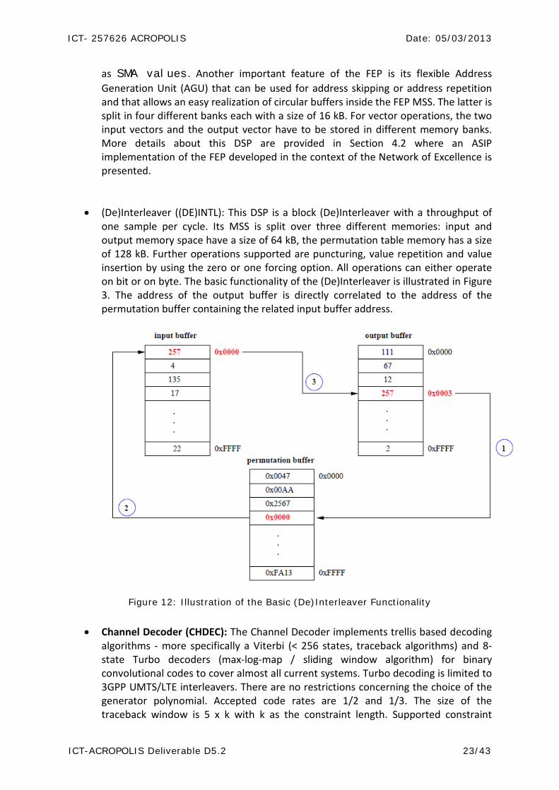
• (De)Interleaver ((DE)INTL): This DSP is a block (De)Interleaver with a throughput of one sample per cycle. Its MSS is split over three different memories: input and output memory space have a size of 64 kB, the permutation table memory has a size of 128 kB. Further operations supported are puncturing, value repetition and value insertion by using the zero or one forcing option. All operations can either operate on bit or on byte. The basic functionality of the (De)Interleaver is illustrated in Figure 3. The address of the output buffer is directly correlated to the address of the permutation buffer containing the related input buffer address.
Figure 12: Illustration of the Basic (De)Interleaver Functionality
• Channel Decoder (CHDEC): The Channel Decoder implements trellis based decoding algorithms - more specifically a Viterbi (< 256 states, traceback algorithms) and 8-state Turbo decoders (max-log-map / sliding window algorithm) for binary convolutional codes to cover almost all current systems. Turbo decoding is limited to 3GPP UMTS/LTE interleavers. There are no restrictions concerning the choice of the generator polynomial. Accepted code rates are 1/2 and 1/3. The size of the traceback window is 5 x k with k as the constraint length. Supported constraint

ICT- 257626 ACROPOLIS Date: 05/03/2013
ICT-ACROPOLIS Deliverable D5.2 24/43
lengths are 7 and 9 for the Viterbi decoder and 4 for the Turbo decoder. For the latter the number of iterations can be programmed from 1 to 8. To increase the performance of standards with short data sets, a tail-biting option has been added to the Viterbi decoder. The MSS of the Channel Decoder is split over three different sections: (1) input data memory (32 kB), (2) output data memory 16 kB) and (3) intermediate data memory (40 kB).
• Mapper: This DSPs perform a set of different modulation schemes which are BPSK,
QPSK, 8PSK, 16-QAM, 32-QAM, 64-QAM and 256-QAM. The input memory of the mapper has a size of 8 kB, the output memory a size of 16 kB. Each input symbol is considered as an address of a Look-Up Table (LUT) with a size of 4 kB from where the related output value is read.
All DSPs and the VCI RAM are connected via a generic Advanced Virtual Component Interface (AVCI) crossbar ([8],[9]). The VCI RAM is used for temporary sample storage on the baseband side. It is mapped onto the global memory map and has a size of 16 kB. The resource allocation of all connected devices is handled by a Round Robin policy.
3.1.2.3 Processing Times
The processing time of all DSPs and DMA transfers is deterministic and can be precalculated if required. Tab. 2.1 illustrates how to compute these times for the DSP engines and DMA transfers when considering the performance of algorithms implemented on the platform.
FEP – DFT/IDFT (vector length L
samples) nL
nLT
22
1*)8
13(2
=
+
++=
FEP – Vector Operations (vector length L
samples)
othersfor 0ncomputatio SMA value if 1
CWLfor 4
112
1
====
+++
+
=
yxyx
yxLT
DE(INTL) number of samples + 16 CHDEC (Viterbi) number of samples + 16 DMA: LEON-DSP (number of bytes/4) + 24
Direct: LEON3-DSP 7 Direct: DSP-LEON3 10
DMA: DSP-DSP (number of bytes/8) + 24 Direct: DSP-DSP 18
Table 2: ExpressMIMO Cycle Counts (T should be read in clock cycles) Memcopy transfers denoted as direct correspond to transfers where LEON3 reads / writes directly in the baseband memory locations by using the global memory map.

ICT- 257626 ACROPOLIS Date: 05/03/2013
ICT-ACROPOLIS Deliverable D5.2 25/43
3.1.2.4 Receiver Emulation using the Library for ExpressMIMO baseband (libembb)
The emulation environment of the ExpressMIMO platform called library for ExpressMIMO baseband (libembb) allows an easy validation and verification of the design in a pure software environment. It is developed by the System-on-Chip Laboratory of Télécom ParisTech and is an open-source C++ library that has already been applied in different European projects like SACRA [9] or PLATA [10] . The functions included in libembb are bit-accurate and represent all functions on the baseband side. The API of libembb provides basic commands for the main CPU and the local UCs as well as synchronization and signaling including error messages. In the future the design will be extended by a cycle accurate SystemC model. Currently, two different implementations are provided: (1) a C++ emulation layer and (2) C language hardware dependent drivers. In case of the so-called synchronous application, no parallelism is supported. The application is designed with the libembb C-API and the code that is run in emulation and on the hardware target is the same. The parallelism of the different DSPs on the platform is not exploited in emulation using a synchronous application. In contrast parallelism has been added for the asynchronous application. The emulation code running on the desktop PC is now multi-threaded and can be used unmodified for hardware processing where it exploits the parallelism of all resources. Figure 4 illustrates this general processing flow.
Figure 13: libembb Processing Flow
3.1.3 Development Methodology The transceiver design methodology applied for any design developed for the ExpressMIMO platform can be divided in several steps.
ICT- 257626 ACROPOLIS Date: 05/03/2013
ICT-ACROPOLIS Deliverable D5.2 26/43
Step one is the development of a purely functional model which is the common starting point for all transceiver designs. The goal of this step is to analyse the algorithmic part of the transceiver, to identify the required resources, the data flow and data dependencies. Thus, it is already possible to identify bottlenecks when processing several transceivers in a multimodal way on the platform. The considered models are typically sequential and do not yet fully exploit the parallelism of the target platform. For the design of the ExpressMIMO platform, the presented libembb library is used for the functional model design. Step two is the cycle accurate HW/SW co-simulation. This step allows to fully exploit the parallelism on the platform. A common approach is the HW/SW co-simulation in discrete event simulators such as Modelsim. The parallelism on the platform includes simultaneous processing of the DSPs, data transfers using the DMAs as well as the preparation of commands in the standardized DSP shell. Results of this step are cycle accurate performance figures of the developed transceiver to get to know the actual performance of the design. Unfortunately the usage of Modelsim is only appropriate for standards with short data sets as the initialization time of a standard like DAB for example is already in the order of 105 cycles. The final step is the transceiver validation on the hardware platform where the design is tested and validated on the real hardware platform. For this step first known snapshots are applied before the signal received through the RF is decoded.
3.2 ASIP Implementation of FEP The ExpressMIMO architecture was extended in a joint work with RWTH in the context of WP7 in order study a different processing architecture for the front-end processor (FEP). We briefly overview the main results here. More detail can be found in [8].
3.2.1 Motivation The primary aim of the collaboration was to overcome the original or C-FEP drawbacks for vector operation processing on short data vectors (e.g. those characteristic of systems like 802.11) by removing the DFT / IDFT unit from the standardized DSP shell and by replacing the vector processing unit by an ASIP solution called A-FEP. Following this approach, the A-FEP can easily be embedded in the baseband processing engine of the ExpressMIMO platform and FEP tasks can be split and scheduled on the two FEP solutions simultaneously. For design evaluation, the A-FEP is not only compared to the C-FEP but also to other ASIP solutions from academia in terms of architectural differences and processing time. The key question addressed by the study is to determine key advantages of ASIPs when compared to other technologies using a case study based on the ExpressMIMO architecture. This provides an existing implementation using more traditional Application Specific Integrated Circuits (ASIC) design approaches. Important factors to be considered for SDR platform design are area and power consumption as well as production costs. One major target is to decrease the area and to minimize the power as much as possible by maintaining the performance. In [13], a detailed overview of the different System on Chip (SoC) implementation techniques is provided. The technologies of interest are
ICT- 257626 ACROPOLIS Date: 05/03/2013
ICT-ACROPOLIS Deliverable D5.2 27/43
• General Purpose Processors that can be divided into two categories, GPP proper for
general purpose applications and microcontrollers for industrial applications. • Digital Signal Processors which are a subcategory of Application Specific Processor
(ASP). DSPs are programmable microprocessors used for extensive numerical real-time applications that are specialized for the digital signal processing domain.
• Application Specific Integrated Circuits (ASIC) which are also a subcategory of ASPs. They are implemented in hardware, usually with a Hardware Description Language (HDL) like VHDL or Verilog.
• Application Specific Instruction-set Processors which are a subcategory of ASPs as well.
• They can be seen as a class of microprocessors coming with a specialized Instruction-Set Architecture (ISA).
The authors of [13] conclude that ASIPs tend to be suitable candidates as they are meant to fill the gap between GPPs and ASICs. Being tailored to a specific application, ASIPs offer a higher flexibility than ASICs by exhibiting a lower energy consumption than GPPs or DSPs at the same time. Or in other words, ASIPs allow to tradeoff the performance of ASICs against the flexibility of GPPs. By additionally taking the advantage of high level tools, the prototyping is facilitated whereas the generated design is not hardware optimized and may not fit the dedicated resource (e.g. FPGA). On the other hand, VHDL allows a resource-efficient FPGA design although the implementation requires a lot of time and resources. This drawback is overcome by tools like System Generator from Synopsis which speed up the VHDL design process by a high-level block design and by the support of fast design modifications.
3.2.2 Conclusions from the study The A-FEP can be included as an additional block in the baseband engine for the execution of latency critical tasks while DFT / IDFT and latency non-critical tasks can be executed by the C-FEP. Observed timing differences are due to the reduced communication overhead of the A-FEP which results in a significant performance gain when operating on standards with short data sets, and which results in a simplified algorithm design. Another key point is that the RTL description of A-FEP version was completely tool-generated and performance, even for the algorithmic component, is comparable if not better than the hand-coded description of C-FEP. This is clearly an important conclusion. Besides the comparison between these two solutions solutions in the ExpressMIMO architecture, the A-FEP has further been compared to recent ASIPs from academia. For an 802.11a/p packet detection algorithm its performance is similar to the ASPE A - a design tailored to the processing of the IEEE 802.11a/n standard. As expected, the performance is worse than the one of a specialized ASIP for synchronization and acquisition described in [13]. The complete analysis can be found in and to a lesser extent in [8].
ICT- 257626 ACROPOLIS Date: 05/03/2013
ICT-ACROPOLIS Deliverable D5.2 28/43
4. Softmodems and protocol stack implementations
4.1 Overview of OAI LTE Implementation (OpenAir4G) The OAI initiative develops open-source MODEM and protocol stack implementation for the ExpressMIMO baseband engine and x86 PC targets. These implementations currently target LTE and 802.11p air interfaces. The LTE implementation, OpenAir4G, provides a standard-compliant LTE Rel-8 implementation of PHY and MAC for a subset of the specifications (36.211[16],36.212[17],36.213[18],36.321[19],36.322[20],36.323[21]36.331[22]). The gnu-C implementation (with x86 SIMD hardware acceleration) can be made to run under any GNU environment, although x86 Linux and RTAI-based targets have only been considered. An overview of the currently supported physical/transport channels and transmission modes is given in the following tables. Compliance of the implementation is being validated in conjunction with various industrial partners and is summarized here. Basic compliance at the PHY is determined using standard LTE test and measurement equipment from Rohde-Schwarz and partners industry-grade equipment.

ICT- 257626 ACROPOLIS Date: 05/03/2013
ICT-ACROPOLIS Deliverable D5.2 29/43
Physical Channel Functionality LTE Compliance PSS TX/RX Validated for 1 antenna port at
eNB (implemented for 1,2) SSS TX/RX Validated for 1 antenna port at
eNB (implemented for 1,2) Cell-specific Reference signals
TX/RX, Modes 1,2,3,4,5,6 1-2 antenna ports at eNB
Validated for 1 antenna port at eNB (implemented for 1,2)
PBCH TX/RX 1,2 antenna ports at eNB
Validated for 1 antenna port at eNB (implemented for 1,2)
PCFICH/PDCCH TX/RX 1,2 antenna ports at eNB All 5 MHz DCI Formats
Validated for 1 antenna port at eNB, DCI Format 1,1A (TDD/FDD), (implemented for 1,2)
PHICH TX/RX 1,2 antenna ports at eNB
Validated for 1 antenna port at eNB (implemented for 1,2)
PDSCH TX/RX 1,2 antenna ports at eNB TX Diversity, 2-antenna Precoding (Mode 4/5/6))
Validated for 1 antenna port at eNB (implemented for 1,2)
PUSCH + UCI TX/RX 1,2 antennas ports at eNB
Validated
PUCCH TX/RX formats 1,1a,1b Validated DRS TX/RX, 1-2 antenna ports at
eNB Validated
SRS TX/RX, 1-2 antenna ports at eNB
Not validated yet, implemented
PRACH TX/RX, 1-2 antenna ports at eNB
Validated (formats 1-3)
Table 3: Physical Channel Support in OpenAirInterface.org (3GPP 36-211)
Coding Methods Functionality LTE Compliance Tail-biting C. code, , TX/RX validated Turbo code TX/RX validated rate-matching (C. code) TX/RX validated Rate-matching (turbo) TX/RX validated segmentation TX/RX validated CRC 24-bit TX/RX validated CRC 16-bit TX/RX validated CRC 8-bit TX/RX validated BCH TX/RX Validated DCI TX/RX, 5 MHz TDD/FDD
formats Validated (format 1,1A,1D,1B)
DLSCH TX/RX Validated ULSCH/UCI TX/RX Validated (subset of UCI
formats)

ICT- 257626 ACROPOLIS Date: 05/03/2013
ICT-ACROPOLIS Deliverable D5.2 30/43
CQI TX/RX Validated CFI TX/RX Validated HI TX/RX Validated
Table 4: Coding and Multiplexing (36.212)

ICT- 257626 ACROPOLIS Date: 05/03/2013
ICT-ACROPOLIS Deliverable D5.2 31/43
Procedure Functionality LTE Compliance Random-Access TX/RX, full procedure,
Connection Establishment, handover, data transfer
Validated
Random-access response TX/RX, full procedure Validated PDCCH procedures TX/RX Validated DL/UL HARQ procedures TX/RX, TDD, no PHICH Not validated CQI/PMI/RI reporting TX/RX, HLC and
Subband PMI on PUSCH Not validated
PUCCH Implemented (formats 0,1a,1b)
Table 5: Physical Layer Procedures (3GPP 36-213)
4.1.1 OpenAir4G Protocol Stack
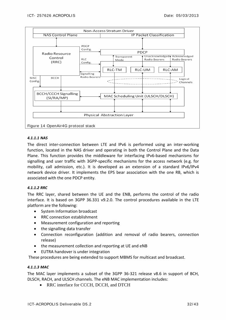
OpenAir4G provides a full real-time protocol stack for a gnu gcc environment implementing a subset of LTE Rel. 8/9 of access stratum as shown in Figure 8 and includes the following blocks:
• Linux Network device driver (kernel) • MAC/RLC/PDCP/RRC and IP • PHY procedures • Can be integrated with openair4G MODEM or abstraction of physical channels,
MODEM is abstracted along with propagation • Can be vectorized for multiple instances (multi eNB, multi UE, combined eNB/UE,
multiple component carriers for carrier aggregation)
ICT- 257626 ACROPOLIS Date: 05/03/2013
ICT-ACROPOLIS Deliverable D5.2 32/43
Figure 14 OpenAir4G protocol stack
4.1.1.1 NAS
The direct inter-connection between LTE and IPv6 is performed using an inter-working function, located in the NAS driver and operating in both the Control Plane and the Data Plane. This function provides the middleware for interfacing IPv6-based mechanisms for signalling and user traffic with 3GPP-specific mechanisms for the access network (e.g. for mobility, call admission, etc.). It is developed as an extension of a standard IPv6/IPv4 network device driver. It implements the EPS bear association with the one RB, which is associated with the one PDCP entity.
4.1.1.2 RRC
The RRC layer, shared between the UE and the ENB, performs the control of the radio interface. It is based on 3GPP 36.331 v9.2.0. The control procedures available in the LTE platform are the following:
• System Information broadcast • RRC connection establishment • Measurement configuration and reporting • the signalling data transfer • Connection reconfiguration (addition and removal of radio bearers, connection
release) • the measurement collection and reporting at UE and eNB • EUTRA handover is under integration
These procedures are being extended to support MBMS for multicast and broadcast.
4.1.1.3 MAC
The MAC layer implements a subset of the 3GPP 36-321 release v8.6 in support of BCH, DLSCH, RACH, and ULSCH channels. The eNB MAC implementation includes:
• RRC interface for CCCH, DCCH, and DTCH
ICT- 257626 ACROPOLIS Date: 05/03/2013
ICT-ACROPOLIS Deliverable D5.2 33/43
• Schedulers • DCI generation • HARQ Support • RA procedures and RNTI management • RLC interface (AM, UM)
UE MAC implementation includes • PDU formats: all control elements and logical channels • RLC interface AM,UM, TM • RRC transparent interface for CCCH and BCCH • Buffer status reporting and scheduling request procedures • Power headroom reporting
4.1.1.4 PDCP
The current PDCP is header compliant with 3GPP 36-323 Rel 10.1.0 and implement the following functions:
• User and control data transfer • Sequence number management • RB association with PDCP entity • PDCP entity association with one or two RLC entities
4.1.1.5 RLC
The RLC layer implements a full specification of the 3GPP 36-322 release v9.3 for all the three mode: transparent mode (TM), unacknowledged mode (UM), and acknowledge mode (AM) with the following characteristics:
• RLC TM (mainly used for BCCH and CCCH) o Neither segment nor concatenate RLC SDUs o Do not include a RLC header in the RLC PDU o Delivery of received RLC PDUs to upper layers
• RLC UM (mainly used for DTCH) o Segment or concatenate RLC SDUs according to the TB size selected by MAC o Include a RLC header in the RLC PDU o Duplication detection o PDU reordering and reassembly
• RLC AM, compatible with 9.3 o Segmentation, concatenation, and reassembly o Padding o Data transfer to the user o RLC PDU retransmission in support of error control and correction o Generation of data/control PDUs
4.2 Specific Extensions of OpenAir4G in the context of Acropolis Two specific extensions to the OpenAir4G software environment have been integrated (still in progress during drafting of this report) in the context of the Network of Excellence, both addressing different issues related to distributed interference management. The first

ICT- 257626 ACROPOLIS Date: 05/03/2013
ICT-ACROPOLIS Deliverable D5.2 34/43
concerns integration of some aspects of the Release-10 specifications dealing with spectrum-aggregation of multiple LTE component carriers. Distributed algorithms for dynamic spectrum allocation will be considered using this development in 2013 in conjunction with WP9. The second deals with distributed signal-processing allowing for an overlay of a short-range secondary network (e.g. an indoor small-cell) on the same carrier as a primary network (e.g. an outdoor macro-cell), where both primary and secondary basestations can collaborate to minimize impact of interference on primary users. One example could be an overlay of a TDD small-cell on the uplink carrier of an FDD macro-cell. This work makes use of the preliminary development undertaken in the CROWN FP7 project which ended in May 2012.
4.2.1 Support for Carrier Aggregation and distributed interference management protocols
4.2.1.1 Overview of Carrier Aggregation in Release-10 LTE
The primary reason for introducing carrier aggregation in LTE is to provide larger bandwidths for end-users under the constraint of spectrum fragmentation. Due to its basic waveform description, LTE is a scalable bandwidth system, allowing for bandwidths covering 1.4, 3, 5, 10, 15 or 20 MHz per carrier. In Release-10, any combination of up to 5 component carriers, depending on the UE capability, can be considered. It is thus theoretically possible to accurately cover an area with a sparse yet wide total bandwidth (100 MHz). The second important aspect is, as is common in cellular systems, that backward compatibility ensured. LTE guarantees that each Release-10 compliant component carrier can be used transparently by a Release-8/9 UE. The third aspect is that it facilitates support of heterogeneous network deployments through cross-carrier scheduling. The latter is made possible by using “clean” primary carriers for signalling and essential services in conjunction with “dirty” secondary carriers for more opportunistic data transmission with the help of robust HARQ mechanisms. The combination of these two features will allow for much higher throughput to end-users and guaranteed quality-of-service for essential services. This makes the cognitive radio paradigm extremely relevant for mainstream wireless technologies. In order to guarantee backwards compatibility with Release-8 UEs the physical layer does not aggregate packets at the level of the codeword. This is a task of the MAC layer scheduler at the eNB which decides how to schedule traffic on the different component carriers offered by the physical layer. The PHY can now transport 2Ncc codewords in one subframe, Ncc , is the number of CC configured for the UE. Aside from signalling in the RRC, the protocol elements above the MAC layer (i.e. RLC,PDCP) see no impact other than higher throughput. The physical layer replicates its procedures (aside from basic signalling which only occurs on the primary CC) on all carriers. From a software perspective, this can be seen simply as a vectorization of the physical layer procedures. An visual description of the above is shown in Figure 6.

ICT- 257626 ACROPOLIS Date: 05/03/2013
ICT-ACROPOLIS Deliverable D5.2 35/43
Figure 15: Carrier Aggregation Protocol Replication at eNB
4.2.1.2 Overview of OAI extensions for Carrier Aggregation The extension is concerned with enabling carrier aggregation capabilities on the OpenAirInterface protocol stack. This requires changes to the RRC, MAC and PHY entities both for the eNodeB and UE. The RRC module was extended to add, delete and modify CCs and perform other control signalling specific to Release-10 UEs such as cross-carrier scheduling, CA-specific measurement configuration, secondary cell search etc. The MAC needs to be extended to support multiple (up to five) CCs at the eNodeB and UE. Regular MAC functions like scheduling, HARQ handling, power control, processing of CQI and ACK/NACKs should include multiple CCs. The scheduler in particular needs to be carefully designed to allow for globally optimal user selection. The current scheduler in OAI is a barebones implementation which does not yet take into consideration issues like user fairness, metric computation, UE-level QoS etc. The PHY processing is replicated for each CC both in the downlink (eNodeB) and uplink (UE). So each CC will have its own HARQ process (per UE), separate modulation, coding and other PHY processing prior to transmission (see Figure 7).
Figure 16: PHY replication for aggregated CCs
ICT- 257626 ACROPOLIS Date: 05/03/2013
ICT-ACROPOLIS Deliverable D5.2 36/43
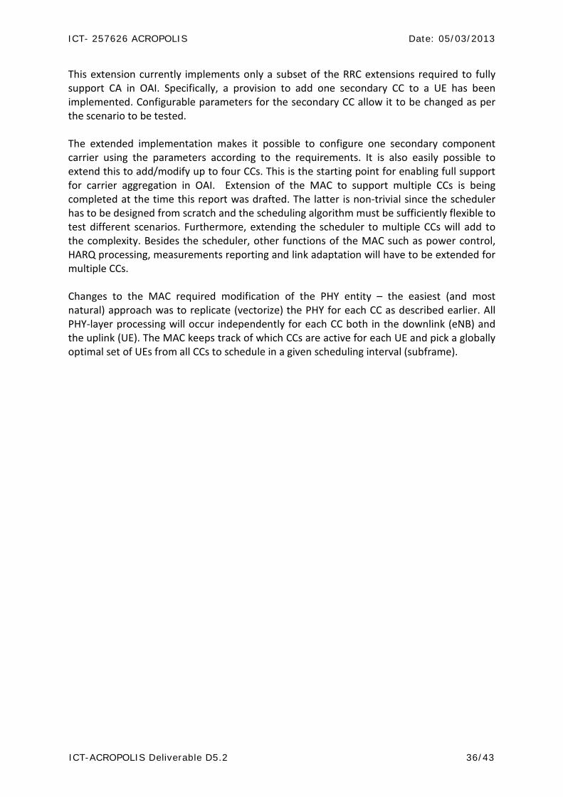
This extension currently implements only a subset of the RRC extensions required to fully support CA in OAI. Specifically, a provision to add one secondary CC to a UE has been implemented. Configurable parameters for the secondary CC allow it to be changed as per the scenario to be tested. The extended implementation makes it possible to configure one secondary component carrier using the parameters according to the requirements. It is also easily possible to extend this to add/modify up to four CCs. This is the starting point for enabling full support for carrier aggregation in OAI. Extension of the MAC to support multiple CCs is being completed at the time this report was drafted. The latter is non-trivial since the scheduler has to be designed from scratch and the scheduling algorithm must be sufficiently flexible to test different scenarios. Furthermore, extending the scheduler to multiple CCs will add to the complexity. Besides the scheduler, other functions of the MAC such as power control, HARQ processing, measurements reporting and link adaptation will have to be extended for multiple CCs. Changes to the MAC required modification of the PHY entity – the easiest (and most natural) approach was to replicate (vectorize) the PHY for each CC as described earlier. All PHY-layer processing will occur independently for each CC both in the downlink (eNB) and the uplink (UE). The MAC keeps track of which CCs are active for each UE and pick a globally optimal set of UEs from all CCs to schedule in a given scheduling interval (subframe).
ICT- 257626 ACROPOLIS Date: 05/03/2013
ICT-ACROPOLIS Deliverable D5.2 37/43
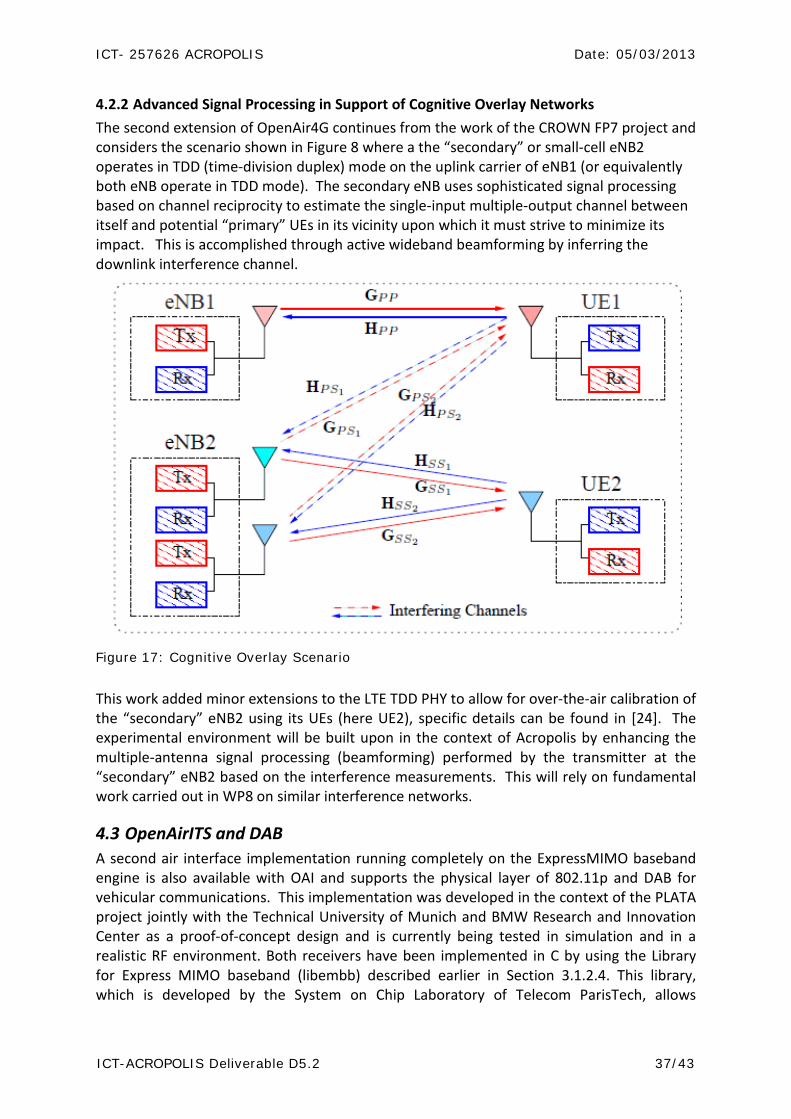
4.2.2 Advanced Signal Processing in Support of Cognitive Overlay Networks The second extension of OpenAir4G continues from the work of the CROWN FP7 project and considers the scenario shown in Figure 8 where a the “secondary” or small-cell eNB2 operates in TDD (time-division duplex) mode on the uplink carrier of eNB1 (or equivalently both eNB operate in TDD mode). The secondary eNB uses sophisticated signal processing based on channel reciprocity to estimate the single-input multiple-output channel between itself and potential “primary” UEs in its vicinity upon which it must strive to minimize its impact. This is accomplished through active wideband beamforming by inferring the downlink interference channel.
Figure 17: Cognitive Overlay Scenario
This work added minor extensions to the LTE TDD PHY to allow for over-the-air calibration of the “secondary” eNB2 using its UEs (here UE2), specific details can be found in [24]. The experimental environment will be built upon in the context of Acropolis by enhancing the multiple-antenna signal processing (beamforming) performed by the transmitter at the “secondary” eNB2 based on the interference measurements. This will rely on fundamental work carried out in WP8 on similar interference networks.
4.3 OpenAirITS and DAB A second air interface implementation running completely on the ExpressMIMO baseband engine is also available with OAI and supports the physical layer of 802.11p and DAB for vehicular communications. This implementation was developed in the context of the PLATA project jointly with the Technical University of Munich and BMW Research and Innovation Center as a proof-of-concept design and is currently being tested in simulation and in a realistic RF environment. Both receivers have been implemented in C by using the Library for Express MIMO baseband (libembb) described earlier in Section 3.1.2.4. This library, which is developed by the System on Chip Laboratory of Telecom ParisTech, allows
ICT- 257626 ACROPOLIS Date: 05/03/2013
ICT-ACROPOLIS Deliverable D5.2 38/43
emulation of the baseband processing part of the platform on a PC as well as an easy verification of the whole design on the platform itself. Hence repeatable and scalable real-time experiments are possible without the need of RF equipment. The next step is the combination of the two receivers on the same hardware-software architecture. This task is quite challenging since the DAB receiver and 802.11p receivers have radically different processing latency requirements. It is worth noting that the OpenAirITS MODEM implementation was used as the basis for the flexible processing architecture comparisons described in Section 3.2.
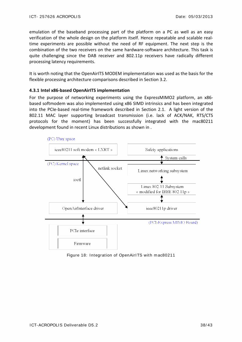
4.3.1 Intel x86-based OpenAirITS implementation For the purpose of networking experiments using the ExpressMIMO2 platform, an x86-based softmodem was also implemented using x86 SIMD intrinsics and has been integrated into the PCIe-based real-time framework described in Section 2.1. A light version of the 802.11 MAC layer supporting broadcast transmission (i.e. lack of ACK/NAK, RTS/CTS protocols for the moment) has been successfully integrated with the mac80211 development found in recent Linux distributions as shown in .
Figure 18: Integration of OpenAirITS with mac80211

ICT- 257626 ACROPOLIS Date: 05/03/2013
ICT-ACROPOLIS Deliverable D5.2 39/43
5. Training and Teaching Activities on OAI The activities related to training as this is a fundamental part of WP5 and linked to education and training activities in WP3.
5.1 OAI Training activities in 2012 EURECOM organized the Acropolis Winter School on Experimental Methods in Wireless Communications which was held at EURECOM in Sophia Antipolis (French Riviera), on 20-22 February 2012. The main target of the school was to expose PhD students and junior researchers to modern experimental methods useful for research in wireless communications, particularly in the areas of hardware and software architectures for wireless platforms, and large-scale network simulation/emulation tools. The school allowed for ample opportunity for students to get hands-on experience with some of these methods. In particular a series of in-depth training sessions covered two different experimental platforms, namely the Rice University WARP platform (organized by the Institute for Networked System, RWTH Aachen) and ExpressMIMO and CardBusMIMO OpenAirInterface.org platforms from EURECOM (organized by the Mobile Communications Department of EURECOM.)
In addition several morning lectures (at least two per day) were given by experts in the field of experimentation for wireless communications. The list of committed speakers was:
• Renaud Pacalet (TelecomParisTech, Sophia Antipolis) : Flexible Hardware and Software architectures for Wireless Communications
• Fabien Clermidy (CEA-LETI, Grenoble): An overview of the MAGALI platform
• Philipp Svoboda (Technical University of Vienna) : Measurement and Modeling of Traffic for Efficient Wireless Network Simulation
• Thanasis Korakis (CERTH (Greece)/New York Polytechnic University) : Methodology and framework for experimental oriented research on wireless testbeds
• Walid Dabbous (INRIA Sophia Antipolis): An overview of NEPI: Network Experimentation
Programming Interface
5.1.1 OAI Labs
The OAI labs took place in the afternoon over the three days consisted of the following modules:
OAI1 (20/02, 16h30; 21/02, 14h00): Introduction to OpenAir4G (3GPP LTE) and OAI MODEM development on ExpressMIMO and CBMIMO1 platforms (20 students per 1.5 hour session, repeated twice over 3 days). Students were introduced to both OCTAVE and C language interfaces to OAI radio platforms and built a piece of an OpenAir4G LTE receiver. 5
ICT- 257626 ACROPOLIS Date: 05/03/2013
ICT-ACROPOLIS Deliverable D5.2 40/43
ExpressMIMO radio stations and 5 CBMIMO1 radio stations were be used.( OAItraining1.ppt)
OAI2 (21/02, 16h30; 22/02, 14h00;): Hands-on OpenAir11p (802.11p) lab session with ExpressMIMO baseband application library (libembb) (10 students per 1.5 hour session, repeated twice over 3 days). This session provided an overview of the libembb DSP software library and a real-time software development methodology for radio MODEMS on an experimental MPSoC architecture. This involved experimentation on the ExpressMIMO baseband engine (5 stations were at the disposal of students.) This covered material described in Section 3 and the 802.11 MODEM implementation described in Section 4.3.
OAI3 (21/02, 14h00; 22/02, 16h30;): Numerical tools for PHY layer abstraction (20-30 students per 1.5 hour session). This session provided an overview of the OpenAir4G PHY simulation methodology and shows how MODEM performance can be modeled for use in large-scale system emulation.
OAI4 (20/02, 14:00; 21/02 16h30; 22/02 16h30;): The training was designed to study and analyze the OpenAir4G LTE protocol stack both in control-plane and data-plane using the software emulation platform. An introduction to the OpenAir4G emulation methodology was provided and two different experiments were designed. In the first experiment, we followed the control plane signaling between an UE and an eNB from the unconnected state to establishing a default data radio bearer (DRB). In the second experiment, we follow service and protocol data unit (SDU and PDU) in the data-plane, namely in PDCP, RLC, and MAC, by sending IP packet to the network device driver, which hands the packet to the protocol stack.
OAI5 (22/02 14h00;): Use-cases in Cognitive Radio and Collaborative Communications. This session describes a few examples where OAI is currently being used for experimental wireless networking and focuses on a cognitive overlay network developed in the context of the CROWN project. The latter was described in Section 4.2.2. Two other examples of OAI in collaborative communications (distributed relaying) from the CONECT and LOLA projects were also described. All three example show how OAI simulation methodology is used prior to hardware integration on a platform.
5.2 Envisaged OAI Training activities in 2013 Another training session similar to the Winter School will be organized in 2013 around the ExpressMIMO2 platform and new software development tools for real-time experimentation. It will most likely be located in Athens, Greece in order to include other partners from WP5 and perhaps include participation of members of the NEWCOM# NoE. This training session will target more interaction between WP5 partners around the two Acropolis scenarios described in Section 4.2.
ICT- 257626 ACROPOLIS Date: 05/03/2013
ICT-ACROPOLIS Deliverable D5.2 41/43
6. Conclusion This document provided an overview of the current status of OpenAirInterface.org both in terms of its hardware and software elements. Specific details on the newest hardware platform, ExpressMIMO2, developed for experimentation in cognitive wireless networking were provided. It is hoped that the explicitly-chosen low-cost design of the platform will be incite partners within the network to invest in OAI technologies for experimental research purposes. The LTE SDR implementations, OpenAir4G, are described in addition to a new 802.11 SDR implementation OpenAirITS. Information on OAI Training activities undertaken in 2012 and those planned for early 2013 were provided.
ICT- 257626 ACROPOLIS Date: 05/03/2013
ICT-ACROPOLIS Deliverable D5.2 42/43
7. References [1] N.-u.-I. Muhammad, R. Rasheed, R. Pacalet, R. Knopp, and K. Khalfallah, “ Flexible
Baseband Architectures for Future Wireless Systems.” In 11th EUROMICRO Conference on Digital System Design Architectures, Methods and Tools, 2008. DSD ’08, pages 39 –46, Sept. 2008.
[2] http://www.gaisler.com/leonmain.html. [3] http://www.xilinx.com. [4] http://ecos.sourceware.org/ecos/docs-2.0/ref/hal-smp-support.html. [5] http://www.mutekh.org. [6] A. Becoulet,”Conception d’un système d’exploitation supportant nativement les
architectures multiprocesseurs hétérogènes à mémoire partagée. “ PhD thesis, L’Universite Pierre et Marie Currie - Paris VI, 2010.
[7] N.-u.-I. Muhammad. Flexible Baseband Architecture Design & Implementation for Wireless Communication Systems. PhD thesis, Télécom ParisTech, 2010.
[8] VSIA consortium: http://www.vsi.org/. [9] Vsi Alliance Virtual Component Interface Standard Version 2 (OCB 2 2.0). [10] C. Schmidt-Knorreck, R. Pacalet, A. Minwegen, U. Deidersen, T. Kempf, R. Knopp, and
G. Ascheid. Flexible Front-End Processing for Software Defined Radio Applications using Application Specific Instruction-Set Processors. In Conference on Design and Architectures for Signal and Image Processing, DASIP’12, oct. 2012.
[11] http://www.ict-sacra.eu. [12] http://www.openairinterface.org/projects/proton_plata.en.htm. [13] O. Schliebusch, G. Ascheid, A. Wieferink, R. Leupers, and H. Meyr.“Application
Specific Processors for Flexible Receivers.” In Proc. of National Symposium of Radio Science (URSI), Poznan (Poland), April 2005.
[14] S. Eberli. Application-Specifc Processor for MIMO-OFDM Software-Defined Radio. PhD thesis, ETH Zürich, 2009
[15] C. Schmidt-Knorreck. Software-Defined Radio Architectures Applied on Car Networks. PhD thesis, Télécom ParisTech, 2012.
[16] 3GPP TS 36.211 V10.1.0 (2011-03), “3rd Generation Partnership Project; Technical Specification Group Radio Access Network; Evolved Universal Terrestrial Radio Access (E-UTRA) and Evolved Universal Terrestrial Radio Access Network (E-UTRAN); Physical Channels and Modulation (Release 10)
[17] 3GPP TS 36.212 V10.1.0 (2011-03), “3rd Generation Partnership Project; Technical Specification Group Radio Access Network; Evolved Universal Terrestrial Radio Access (E-UTRA) and Evolved Universal Terrestrial Radio Access Network (E-UTRAN); Multiplexing and channel coding (Release 10)
[18] 3GPP TS 36.213 V10.1.0 (2011-03), “3rd Generation Partnership Project; Technical Specification Group Radio Access Network; Evolved Universal Terrestrial Radio Access (E-UTRA) and Evolved Universal Terrestrial Radio Access Network (E-UTRAN); Physical Layer Procedures (Release 10)”.
[19] 3GPP TS 36.321 V10.1.0 (2011-03), “3rd Generation Partnership Project; Technical Specification Group Radio Access Network; Evolved Universal Terrestrial Radio
ICT- 257626 ACROPOLIS Date: 05/03/2013
ICT-ACROPOLIS Deliverable D5.2 43/43
Access (E-UTRA) and Evolved Universal Terrestrial Radio Access Network (E-UTRAN); Medium Access Control (MAC) protocol specification (Release 10)”.
[20] 3GPP TS 36.322 V10.1.0 (2011-03), “3rd Generation Partnership Project; Technical Specification Group Radio Access Network; Evolved Universal Terrestrial Radio Access (E-UTRA) and Evolved Universal Terrestrial Radio Access Network (E-UTRAN); Radio Link Protocol (RLC) Specification (Release 10)”.
[21] 3GPP TS 36.323 V10.1.0 (2011-03), “3rd Generation Partnership Project; Technical Specification Group Radio Access Network; Evolved Universal Terrestrial Radio Access (E-UTRA) and Evolved Universal Terrestrial Radio Access Network (E-UTRAN); Packet Data Convergence Protocol (PDCP) Specification (Release 10)”.
[22] 3GPP TS 36.331 V10.1.0 (2011-03), “3rd Generation Partnership Project; Technical Specification Group Radio Access Network; Evolved Universal Terrestrial Radio Access (E-UTRA) and Evolved Universal Terrestrial Radio Access Network (E-UTRAN); Radio Resource Control Protocol (RRC) Specification (Release 10)”.
[23] http://wireless.kernel.org/en/developers/Documentation/mac80211 [24] Bassem Zayen, Boris Kouassi, Raymond Knopp, Florian Kaltenberger, Dirk Slock, Irfan
Ghauri, and Luc Deneire, “Software implementation of spatial interweave cognitive radio communication using OpenAirInterface platform,” in International Symposium on Wireless Communication Systems 2012 (ISWCS’12), Paris, France, Aug. 2012.