locomotion skills for simulated quadrupedsvan/papers/2011-tog-quadruped/paper.pdflocomotion skills...
TRANSCRIPT

To appear in the ACM SIGGRAPH 2011 conference proceedings
Locomotion Skills for Simulated Quadrupeds
Stelian Coros1,2 Andrej Karpathy1 Ben Jones1 Lionel Reveret3 Michiel van de Panne1 ∗
1University of British Columbia 2Disney Research Zurich 3INRIA, Grenoble University, CNRS
Figure 1: Real-time physics-based quadruped simulations of gaits (walk, trot, canter, transverse gallop, pace, rotary gallop), gait transitions,sitting and standing up, targeted jumps, and jumps on-to and off-of platforms.
Abstract
We develop an integrated set of gaits and skills for a physics-basedsimulation of a quadruped. The motion repertoire for our simu-lated dog includes walk, trot, pace, canter, transverse gallop, rotarygallop, leaps capable of jumping on-and-off platforms and over ob-stacles, sitting, lying down, standing up, and getting up from a fall.The controllers use a representation based on gait graphs, a dual legframe model, a flexible spine model, and the extensive use of inter-nal virtual forces applied via the Jacobian transpose. Optimizationsare applied to these control abstractions in order to achieve robustgaits and leaps with desired motion styles. The resulting gaits areevaluated for robustness with respect to push disturbances and thetraversal of variable terrain. The simulated motions are also com-pared to motion data captured from a filmed dog.
1 Introduction
Quadrupedal animals form an important part of the world aroundus. It is therefore not surprising that cats, dogs, mice, horses, don-keys, elephants, and other animals, real or mythical, make reg-ular appearances in games, films, and virtual world simulations.Games which use interactive quadruped animation include Zoo Ty-coon, Red Dead Redemption, Cabela’s African Safari, and Assas-sin’s Creed. Example films include Lord of the Rings, Chronicles ofNarnia, and Cats and Dogs, to name but a few. Quadruped move-ment is extremely rich because of the many possible gaits and thevariations in body size and body proportions, e.g., from shrews toelephants. There exist a multitude of ways in which the skeletonand legs can support the locomotion. The difficulty of modelingsuch a diverse set of motions is further compounded by the paucityof available motion capture data.
As was first proposed two decades ago [Raibert and Hodgins1991], the use of forward dynamics simulation with suitable con-trollers offers one possible approach for creating interactive, reac-tive quadruped motions. We build on this general approach with thefollowing contributions:
∗scoros|andrejk|jonesben|[email protected], [email protected]
• We develop several abstractions for use in quadruped simula-tion, including a dual leg frame model, a flexible abstractedspine, and the extensive use of internal virtual forces. Theseform part of a flexible vocabulary for the design of quadrupedmotions.
• We demonstrate the creation of walk, trot, pace, canter, andtransverse and rotary gallop gaits of varying speeds for a sim-ulated dog using these control abstractions. The gaits are au-tomatically tuned (optimized) to satisfy a variety of objec-tives. We compare our motions with captured motion for adog. We evaluate the robustness of the gaits with respect togait transitions, pushes, and unexpected steps.
• We develop a flexibly parameterized jump that can be exe-cuted from various initial trotting speeds. This allows the sim-ulated quadruped to jump onto and off of platforms, jump overobstacles, and jump over gaps. We further develop controllersfor sitting, lying-down, and standing up.
2 Related Work
A mix of kinematic and dynamic methods have been applied toquadruped animation, dating back over a quarter century. A com-prehensive recent survey of quadruped animation work is given in[Skrba et al. 2008]. The following survey is heavily focused oncontroller-based methods, and even then it is selective because ofthe breadth of previous work in this area.
Procedural and trajectory-based methods: The early work ofGirard and Maciejewski [1985] proposes the use of gait patterns,foot location splines, inverse kinematics, and body location that isconstrained by simplified body dynamics. Blumberg and Galyean[1995] develop a multi-layer kinematic approach as the simulatedmotor system of a dog, with a focus on supporting higher level be-haviors. The game of Spore [Hecker et al. 2008] develops methodsfor generating procedural animation for arbitrary legged creatures,including locomotion patterns. Torkos and van de Panne [1998] ap-ply trajectory optimization techniques to an abstracted quadrupedmodel to obtain motions that are compatible with given foot loca-tions and timing patterns. Wampler and Popovic [2009] developa two-level optimization procedure for physics-based trajectoriesof periodic legged locomotion and use it to explore connections be-tween form and function. Kry et al. [2009] explore the use of modaldeformations as the basis for developing periodic gait patterns di-rectly from the geometry of a dog model.
2D forward dynamic simulations: The dynamic simulation ofquadruped gaits is a shared goal across animation, robotics, and
1

To appear in the ACM SIGGRAPH 2011 conference proceedings
biomechanics. Physics-based simulations are typically better suitedfor modeling unscripted interactions with the environment thankinematic models. 2D sagittal plane simulations can reveal muchabout the nature of quadruped gaits without dealing with the full in-tricacies of 3D motion, and have thus often been used for the devel-opment and analysis of quadruped gaits and control strategies. Vanden Bogert [1989] develops a 2D rigid body model with significantaspects of the motion constrained so as to follow given motion andground-reaction force data. Marhefka et al. [2003] develop a con-trol strategy based on fuzzy logic to produce simulated planar gal-lops. Krasny and Orin [2004] use a search algorithm to explore thespace of open-loop 2D gallops. Herr and McMahon [2001] developand analyze feedforward and feedback strategies for the transversegallop of a horse, as tested using a 10-link planar simulation. Wongand Orin [1995] develop control strategies for quadruped standingjumps using a simplified planar model.
3D forward dynamic simulations of quadruped gaits are in-troduced by Raibert and Hodgins [1991], who develop controlstrategies for trotting, bounding, and galloping gaits for a robotquadruped with a rigid body and extensible legs. Kokkevis et al.[1995] present a hybrid kinematic-and-dynamic controller and sim-ulation for a 3D dog with a rigid trunk that can walk and trot usinga linear programming framework. Ringrose [1996] demonstratesin simulation that gaits such as transverse and rotary gallops canbe self-stabilizing for appropriate body and leg design and circu-lar foot profiles. Van de Panne [1996] explores the use of op-timized open-loop, passively-stable control strategies to generatedynamically-simulated 3D locomotion for a wide-stanced cat, in-cluding walk, trot, bound, and rack gaits. Krasny and Orin [2006]employ a multi-objective optimization to develop stable gallops fora 9-link 3D simulation. Our work improves upon the state of the artin 3D quadruped simulation in a number of ways, as outlined at theend of this section.
Quadruped Robots: Numerous quadruped robots have been de-veloped, along with control strategies that are compatible with theirspecific mechanical design. The Raibert quadruped [Raibert 1986]and BigDog [Buehler et al. 2005; Playter et al. 2006] provide semi-nal demonstrations of movement that is highly robust to pushes andmany different types of terrain, e.g., snow, mud, and steep hills. Themost developed gait simultaneously moves diagonally-opposite legpairs, as in a trotting gait. The SCAMPER robot provides an earlydemonstration of a dynamic and symmetric ‘bounce’ gait [Furushoet al. 2002]. The SCOUT robot is a small robot capable of walking,climbing, and galloping [Poulakakis et al. 2005] using one-degree-of-freedom legs. Walking gaits have been automatically optimizedfor the Sony AIBO robot using policy gradient methods [Kohl andStone 2004]. Numerous control strategies have been developed forthe LittleDog robot, e.g., [Kolter et al. 2008; Zucker et al. 2010].These have typically focused on slower gaits and rough terrain thatdemands careful motion planning. CPG-based control strategiesare demonstrated in [Tsujita et al. 2001] and are developed for dy-namic walking over uneven terrain for the Tekken2 robot [Kimuraet al. 2007].
Biped Control: The development of physics-based animated char-acters that can walk and run has been a difficult problem that hasrecently seen significant progress, e.g., [Hodgins et al. 1995; Laszloet al. 1996; Yin et al. 2007; Sok et al. 2007; Muico et al. 2009; Yeand Liu 2010; Lee et al. 2010; Coros et al. 2010; Wu and Popovic2010; de Lasa et al. 2010]. Faloutsos et al. [2001] develop a frame-work for the serial composition of controllers for a simulated hu-man model. A comprehensive review of the extensive prior art onthe problem of biped control is beyond the scope of this paper. Theideas developed for biped control provide insights and inspirationfor quadruped control. However there are many open questions inextending these methods to quadrupeds. Which approaches will
Figure 2: Controller Overview.
Figure 3: Abstract quadruped model. The model has separatefront and back leg frames which are each use independent foot plac-ment.
scale well? What are good quadruped motion objectives? Howcan quadruped motions be authored in the face of a lack of motioncapture data? Which abstract models are suitable to use in con-trol computations? How should the flexible spine be modeled? Weprovide answers to some of these questions in this paper.
Our work: The methods and results developed in this paper canbe distinguished from previous work in a number of ways. We de-velop a flexible abstract spine model which helps achieve more nat-ural motion during fast gaits such as the gallop. The flexible spineconnects front and back leg frames, which together form a dual legframe model, with each leg frame making independent decisionswith regard to footstep placement, height control, and pitch con-trol. The controller also exploits gait-specific feed-forward (phase-based) internal virtual forces which are tuned using optimization.The capabilities of a simulated quadruped can be evaluated alongany number of dimensions, including the number of supported gaitsand gait transitions, their speed, ability to turn, robustness to exter-nal perturbations and terrain, similarity to known animal quadrupedgaits, and the number of other skills that can be performed, e.g.,leaping, sitting, and getting up after a fall. We evaluate our simu-lated quadruped along many of these dimensions.
3 Quadruped Gait Controllers
A good control representation should be compact, expressive, andprovide robust motion when perturbed. Figure 2 provides a struc-tural overview of the various components of the quadruped con-troller developed in this paper, each of which will be described inmore detail shortly. The controller also makes use of the quadrupedabstraction shown in Figure 3. As illustrated, this model views thequadruped in terms of front and rear leg frames connected by aflexible spine. Various components of the controller are designeddirectly with this quadruped abstraction in mind, such as the vir-tual forces, the gait graphs, and various trajectories. Many of thetrajectories and parameters that help define the controller are tunedin a separate offline optimization stage which will is detailed in thesubsequent section (§4).
The overall control loop provides torques to a forward dynamicssimulator at every time step, as shown in Figure 2. The forward dy-
2

To appear in the ACM SIGGRAPH 2011 conference proceedings
namics simulation is treated as a black box; the controller does notexploit any specific knowledge about the equations of motion at anytime step. The computed torques arise from two sources: via virtualinternal forces that are applied via Jacobian transpose control, andvia joint control that compute torques using proportional-derivative(PD) controllers. Torques from these two sources are then summedtogether. Pseudocode of the overall control loop is provided in theAppendix.
3.1 Gait Controller Details
Understanding the controller requires understanding the types ofcomponents from which it is constructed (Figure 2) as well ashow these components are used to drive the motion of the abstractquadruped model (Figure 3).
Gait graphs: Quadruped gaits are characterized in large part by thetiming and relative phasing of the swing and stance phases of eachof the legs. This is captured by the gait graph and the overall strideperiod, T . Figure 4 shows the gait graphs for the six gaits modeledin this paper. Progress made within a stride is defined by the gaitphase, Φ ∈ [0, 1), computed as Φ = t/T , where T is the desiredgait period. We further define progress within the stance phase orswing phase for a leg using φ ∈ [0, 1), Some aspects of motion aremodeled as a function of gait phase, such as the desired height andpitch of the hips. Other aspects are modeled as a function of stanceor swing phase, such as the swing foot height trajectories. Withthe exception of the canter, we obtain the gait graphs from trackingof experimental video data recorded for a dog [Abourachid et al.2007]. Extracts of the video are included in the video accompany-ing this paper and experimental gait graphs measured over severalcycles of motion are included in the supplemental material. For thepace, we use the timing for the trot, but applied to left and rightpairs instead of diagonal pairs. For the canter, we estimate a gaitgraph based on data provided by Alexander [1984].
Virtual forces are one of the two primary sources of computedtorques, as shown in Figure 2. These allow the skeletal structureto be largely abstracted away by specifying coordinated sets of in-ternal torques. A virtual force, F , is applied by using the Jaco-bian transpose to compute the required internal torques accordingto τ = JTF [Paul 1981]. The virtual forces can be applied atspecific points or can be applied to derived variables such as thecenter of mass of a collection of links [Sunada et al. 1994; Prattet al. 2001]. A base link must be specified for each virtual force.Figure 5 illustrates the terminology we shall use to describe the ap-plication of virtual forces. In the shown example, the virtual forcespecifies torques in the back that help to raise the front of the body.
Joint control provides the second source of computed torques.With the exception of the hip joints of legs in a stance phase (seecomputation of τstance), all joints in the quadruped have propor-tional derivative (PD) controllers that are active at all times. Whilevirtual forces provide many of the core functional aspects of themotions, e.g., using the stance legs to accelerate the front or rear ofthe body forwards or upwards, the joint control remains necessaryto control the overall shape of the legs and body. Target angles areprovided by predefined trajectories (head, neck, and tail), inversekinematics (legs), or interpolated leg frame orientations (spine).The orientations of the head, the feet, and the leg frames are con-trolled with respect to a desired world-frame orientation, while allother joints servo to a desired local orientation, i.e., with respect totheir parent link. The PD joint angle gains, kp and kd, are set tofixed values, i.e., they are not gait dependent.
Leg frames: The abstracted quadruped allows the controller designto be largely independent of the specifics details of the skeleton,such as the geometry and number of skeletal links used to model
(a) Walk.
(b) Trot.
(c) Pace.
(d) Canter.
(e) Transverse gallop.
(f) Rotary gallop.
Figure 4: Gait graphs. The red stripe indicates the current time orgait phase. Swing phases are drawn as solid bars. Currently activeswing phases are colored green.
specific body parts. The abstract quadruped model consists of frontand rear leg frames, as shown in Figure 3. The frames are definedby the local coordinate frames of the articulated links of the spineto which the legs are attached. For the hind legs this correspondsthe pelvis. The front legs are modeled as being directly attached toa link of the spine, which abstracts away the motion of the scapula.The height and orientation of the leg frames are key features whosemotion is regulated by the controller. The leg frames are used asbase links for all the virtual forces in the controller. We shall alsouse ‘leg frame’ to refer to the link together with its pair of legswhere this can be done without introducing ambiguity.
Stance legs are largely responsible for controlling the motion ofthe leg frames. We first describe the control of the leg frame pitch,which is accomplished using the sum of torques applied to a givenleg frame. Each leg frame receives applied torques from the jointsthat connect it to the stance leg(s), swing leg(s), and the neighbor-ing spine segments, i.e., τLF = τstance + τswing + τspine. Here,τstance is the sum of all hip torques for the stance legs attached to agiven leg frame, and τswing and τspine define analogous quantitiesfor the swing legs and neighboring spine segments. Given a desired
3

To appear in the ACM SIGGRAPH 2011 conference proceedings
Figure 5: Virtual forces as a control abstraction.
world-frame orientation for the leg frame and its current orienta-tion, a desired value of τLF is computed with a PD-controller. Inorder to achieve the desired τLF , the positions of the hip joints areleft uncontrolled, leaving τstance free to be computed according toτstance = τLF−τswing−τspine. This is analogous to the treatmentof the stance hip in the SIMBICON framework [Yin et al. 2007]. Ifa leg frame has both of its legs in stance, the desired torque is sharedequally among both stance joints. If the leg frame has both legs inswing, then τLF cannot be achieved and the leg frame orientationis no longer actively controlled. In order to engage the spine in cre-ating full body motions, we can also choose to have the spine helpin applying τLF to the leg frames. We currently apply this strategyto the front leg frame by requiring the spine to assume 50% of therequired torque, while the stance legs assume the remainder. With-out any engagement of the spine, we find that the torso exhibits asmall wobble from side to side in some gaits. An equivalent strat-egy could be applied to the rear leg frame, although we have notexplored this.
We next explain the virtual forces that are used to help guide themotion of the leg frames. First, a virtual force Fh is used to regu-late the leg frame height to follow a height trajectory hLF (Φ) us-ing a PD controller according to Fh = kpe + kde, where e =hLF (Φ)− h. Second, a virtual force Fv is used to regulate the legframe velocity according to Fv = kv(vd− v). Third, a leg-specificvirtual force FD(D) implements a phase-dependent force that iscustomised for each stance leg. This allows for modeling the indi-vidualized role of each leg in gaits such as the dog gallop [Walterand Carrier 2007]. Here, D measures forward progress in the gaitand is computed as the ground-plane projection of PLF − Pfoot,where PLF is the location of the origin of the leg frame, and Pfoot
is the location of the foot of a given leg. FD(D) initialized to zeroand is tuned automatically through optimization (§4).
The virtual forces described above, i.e., Fh, Fv, and FDi, are intro-duced to guide the motion of the leg frames, as illustrated with thedashed arrows in Figure 6. Achieving these virtual forces requiresthe use of the stance legs. This can be done in two ways: (1) thestance feet can be used as the base links to apply the desired appliedforces on the leg frames; or (2) the leg frames can be used as baselinks which are then used to apply equal-and-opposite forces on thestance feet. However, the virtual force abstraction assumes that thebase link acts as a stable anchor for the given chain of links. Withthis in mind, the mass and connectivity of the leg frames make thema better choice for base link than the stance feet. Because the forcesFh and Fv are not associated with any particular stance leg, they areshared equally across all stance legs. The net virtual force to be ap-plied to a stance foot i is thus given by Fi = −FDi−Fh/n−Fv/n,where n is the number of stance legs for the leg frame that stanceleg i belongs to. If the leg frame has no stance legs, then no virtualforce is applied, i.e., Fi = 0 for all legs belonging to that leg frame.The virtual forces that are realized for each leg are illustrated in Fig-ure 6 with solid arrows. The thick colored lines illustrate the chainof links spanned from the base link, i.e., the leg frame, to the point
Figure 6: Virtual forces used in the controller.
of application of the virtual force, i.e., the foot. Figure 6 also illus-trates an example gravity compensation force, Fg , and an exampleswing leg force, Fsw. These will be elaborated shortly. It is alsoworthwhile noting that Fi is a net desired virtual force exerted byleg i; it is not the final net force seen by that leg. The actual forcesthat are transmitted through the leg remain unknown until after theequations of motion have been resolved for the current time step.
While virtual forces control the overall function of the stance legs,they leave their internal shape unconstrained. To retain control overthe general shape of the multijointed leg, a target position is com-puted for the foot based on its current position on the ground andthe desired height of the leg frame. Inverse kinematics (IK) is thenused to compute target joint angles for PD-controllers at the joints.As illustrated in Figure 2, joint control torques and virtual forcetorques are simply summed.
Swing legs are controlled to follow desired swing foot trajectoriesfrom the toe-off location, P1, to a target foot-strike location, P2.Given the location of the foot, inverse kinematics is then used tocompute target joint angles for the individual joints, which are thentracked using PD-controllers. The target location is computed usinga velocity-based foot placement model: P2 = PLF +(v−vd)sfp,where PLF is the default stepping location relative to the leg framefor each leg, and sfp is a scale factor. These parameters are tunedin the gait optimization phase. Given P1 and P2, the foot height isdefined by a trajectory, hsw(φ), which is distinct for the front andrear legs. The target position in the ground plane follows a linearpath between the two points according to P = (1 − tsw)P1 +tswP2, where tsw advances with the swing phase of the given leg.While using tsw = φ is adequate from a functional point of view,we introduce the flexibility to allow the swing legs to trail behindor advance forward more quickly by defining a piecewise linearfunction tsw(φ). This is initialized to tsw = φ and is refined duringoptimization to enable more natural swing leg trajectories.
Swing leg tracking force: In the absence of high PD-gains, theIK + PD-controller scheme described above does not provide suf-ficiently accurate foot tracking for high speed gaits with swing du-rations as short as 200ms. As a more reliable alternative to simplyincreasing the PD-gains, an additional internal virtual force, Fsw,is introduced to pull the foot location towards its desired target lo-cation using a virtual spring and damper. The proportional gain forthis foot tracking controller, kft follows a trajectory kft(φ). Thistrajectory is then tuned during the optimization phase. The joint-based PD-controllers are still retained in order to retain control overthe shape of the multijointed leg. Early or late termination of swingmay occur due to disturbances. An early foot strike proceeds on toa stance phase for swing phases φ > 0.8. A late foot strike invokesa lowering of the target foot location by a fixed offset ∆h.
Inverse kinematics: The same IK method is used for stance legsand swing legs. The solution is simple in nature because the world-relative foot pitch angle is known as a function of the leg swing
4

To appear in the ACM SIGGRAPH 2011 conference proceedings
phase or stance phase. An analytic two-link IK solver then deter-mines the position of the knee. The plane in which the IK chainacts is defined by a normal that is fixed in the leg-frame coordinatesystem, and the location of the relevant shoulder or hip joint.
Spine: Abstract modeling of the spine makes its control indepen-dent of the number of links used to model it. The leg frames eachhave desired world-frame orientations Ω(Φ). The difference in ori-entation, as computed using quaternions, is divided evenly amongthe n−1 intermediate joints for the n-links that comprise the back,including the leg frames links. These joints are then driven to theirtarget orientations using PD-controllers. The stiffness of the backis determined by the gains of the PD-controllers in the spine and isalways held fixed.
Neck, Head, and Tail: The neck and head have associated pitchtrajectories, Ωnh(Φ), modeled relative to the world frame. Theseare tuned automatically during optimization to minimize head wob-ble. The tail is controlled using local target angles at all joints.These target angles are held fixed over time. The base link of thetail is raised at higher speeds and the tail is also moved out of theway for sitting motions.
Gravity compensation removes the impact of gravity on the swinglegs, neck, head, and spine. This is achieved using virtual forces,F = −mg, applied at the center of mass of the relevant links.For swing legs, the parent leg frames are used as base links forthe virtual forces. For the neck and head, the closest grounded legframe is used as the base link. This is usually the shoulders. Gravitycompensation is also applied to the spine links. The virtual force isshared across the front and rear leg frames with respective weightsof w and 1 − w, where w ∈ [0, 1] is the fractional distance alongthe spine of the given link, with w = 1 at the front leg frame andw = 0 at the rear leg frame.
Foot control adds toe-off and foot-strike anticipation to the gaits.This affects only the pitch of the foot, i.e., in the sagittal plane.Toe-off is modeled with a linear target trajectory towards a fixedtoe-off target angle θa that is triggered ∆ta seconds in advance ofthe start of the swing phase, as dictated by the gait graph. Foot-strike anticipation is done in an analogous fashion with respect tothe anticipated foot-strike time and defined by θb and ∆tb. Theparameters θa, θb,∆ta,∆tb are tuned automatically during the gaitoptimization phase.
Steering is implemented by changing the desired yaw angle of thefront shoulders. This allows for moderate-speed turning behaviors,as the gaits are naturally robust to such variations. Faster changes indirection could possibly be achieved with the help of optimizationor planning specific to such motions.
3.2 Gait Controller Summary
Feedback loops are implicitly or explictly embedded in thepreviously-described components in a number of ways. The feed-back mechanisms are local in nature, i.e., taken individually, theydo not require knowledge of the global state or the full equationsof motion of the quadruped. The principal feedback mechanismsare: (1) The sagittal and coronal foot placement is adapted usingthe foot placement model. This is similar in nature to that used inprior quadruped work, e.g., [Raibert and Hodgins 1991]. (2) Thevelocity is further regulated using virtual forces at each leg frame,Fv . This is a type of virtual model control [Pratt et al. 2001]. (3)The leg frames have feedback paths for regulating height and pitch.The height is controlled with the virtual force, Fh. The pitch ofthe leg frames is controlled with respect to a desired world frameorientation, ΩLF . This is done via the PD-controller that computesτLF , which is then implemented using a combination of the stance
hips and the spine. (4) Knowledge about vertical orientation is em-bedded in the PD-controllers that servo with respect to desired ori-entations in the world frame. This applies to the head-and-neck(Ωnh), feet (θa, θb), and leg frames(ΩLF ). The target orientationsare part of the set of parameters that are optimized offline. (5) Lo-cal joint feedback occurs in the PD controllers that help regular-ize the internal shape of the legs and the spine. (6) Early and lateswing termination are sensed and reacted to. Early contact triggersa change to stance phase for the given leg, while a late foot striketriggers a fixed leg extension. (7) The gait is adapted as a functionof the current velocity, as described in §4. For example, a gallopingquadruped that is pulled back with an external force will revert to acanter, trot, or walk as needed.
Trajectories control many key components in the controller. Theseare summarized in Figure 2. The trajectories are modeled usingpiecewise linear segments and use 4–6 control points. The trajecto-ries are all initialized to constant values and are then further tunedalong with other parameters during an optimization phase, as willbe described below.
4 Gait Optimization
The control mechanisms and their default initialization allow forbasic versions of quadruped gaits. We further use optimization toproduce particular styles of gaits, including the tuning of gaits tomore closely resemble the gaits of a dog. The free parameters in-clude all the trajectory-based parameters; the stride duration; thestep lengths for each leg; the foot placement feedback gain, sfp;the foot control parameters, θa, θb, ta, and tb; and the gains usedin specifying Fv and Fh for the leg frames. This comprises 144parameters for asymmetric gaits (canter, gallop) and approximatelyhalf that for symmetric gaits (walk, trot). The complete list of pa-rameters is provided in the supplemental material.
Motion capture data can play a very useful role in developing suit-able trajectories and parameter settings for quadruped motions, al-though it is not a requirement. Animators have long used and stud-ied reference video in the development of more natural motions,and our work is no exception in this regard. Our reference dataconsists of a set of 2D marker positions of the feet, shoulders, andhips that we have tracked from video [Abourachid et al. 2007] andwhich we correct for perspective and scale. The reference motionshelp in achieving more natural walk, trot, and gallop gaits, via thefd term in the objective function to be described below. The can-ter, pace, parameterized leaps, sit, lie-down, and get-up motions aredeveloped without the use of reference data.
The objective function to be minimized is defined as:
fobj(P ) = wdfd + wvfv + whfh + wrfr
where fd measures the deviation of the motion from available ref-erence data (m), fv measures the average deviation from the de-sired speed in both sagittal and coronal directions (m/s), fh mea-sures head accelerations (m/s2), and fr measures whole body ro-tations (degrees). These terms are weighted usingwd = 100, wv =5, wh = 0.5, wr = 5. This objective function is used for all gaits,although the initial parameter values, initial quadruped state, targetvelocities, gait graph, and reference data will be different for eachspecific gait. The fd term is computed with the help of markersplaced on the simulated dog in locations that approximate the lo-cations for the available markers in the reference video data. fdthen penalizes a weighted sum-of-square distances between eachcorresponding pair of markers. We use markers on the feet, shoul-der and hips, and top of the head. The foot tracking deviationswere weighted less than the remaining distances by including anadditional multiplicative factor of 0.4. The fr term measures the
5

To appear in the ACM SIGGRAPH 2011 conference proceedings
Figure 7: Evolution of the objective function as a function of opti-mization iterations from three different initial parameter settings.
difference between the desired heading and the actual heading ofthe character, as measured in degrees, by the arccos(x · x), wherex and x are the actual and desired forward pointing axes of a legframe. This ensures that the quadruped runs forwards rather thansideways. The velocity error term, fv , is defined as ||v − vd||, andencompasses both sagittal and coronal directions. v is the mean ve-locity as measured over a stride. The desired velocity in the coronalplane is zero. The desired velocity in the sagittal plane is an inputparameter for the desired gait.
A greedy stochastic local optimization algorithm is used. On anygiven iteration, a new parameter vector P ′ is generated by perturb-ing the current best solution according to P ′ = P +S ∆P , where∆P ∼ U(P − 0.1R,P + 0.1R). R = Pmax − Pmin definesthe allowable range of parameter values. S is a parameter selectionvector where each component of S is set to 1 with a 20% probabil-ity and 0 otherwise, and represents an entry-wise multiplication,i.e., the Hadamard product. If f(P ′) < f(P ) then P ′ replaces Pas the current best solution. We speculate that many other choicesof optimization method would also likely be successful. The suc-cess of a greedy optimization algorithm is indicative of the locallysmooth nature of the optimization problem.
The robustness of the gaits is enforced by evaluating the objectiveover eight different scenarios for each parameter evaluation, withforces up to 350N applied for 0.1s on either the shoulders or hipsduring the second gait cycle. Between 7 and 15 locomotion cycles(approximately 6 seconds of simulation time) are tested for eachevaluation, with higher speeds requiring more cycles. The initialstate for each evaluation is obtained from the limit cycle of the cur-rent optimal motion. A gait at a specific desired speed is createdusing the fv term in the optimization. When optimizing for thesame gait at several speeds, we first optimize to create the lowerspeed gaits and then optimize for faster gaits in fixed increments.
In general we optimize a gait for a specific speed using 1, 000 −2, 000 evaluations and then increase the desired speed. This strat-egy is successful in beginning from an in-place canter or gallop to afull-speed canter or gallop. Optimizing a single gait takes between2–10 hours in a single threaded implementation. Figure 7 illustratesthe evolution of the objective function from three different initialparamater settings for a 1m/s trot. The initial parameter valuesfor Test 2 and Test 3 are derived from those of Test 1 by addingan offset ∆p ∼ U(−R/2, R/2), where U is the uniform distri-bution and R represents the allowed range for each variable. Allthree optimizations achieve very similar objective function valuesand produce visually similar gaits. The optimization makes signifi-cant alterations to the default initial values. For example, the heighttrajectory for the front and rear leg frames are initialized to constantvalues of 47cm and 45cm, respectively and changed to 35− 52cmwithin an optimized canter cycle. We attribute the success of thegreedy optimization strategy to the generally well behaved nature
Figure 8: Video data for capture of reference motions.
of the control representation as well as an initial gait that is alreadyfunctional in many respects.
Gait Selection and Transitions
The gait and gait parameters are selected as follows. Given thecurrent speed, v and a goal speed, v, a desired speed is computedat each time step according to vd = min(v, v + 0.5) if v > v,and vd = max(v, v − 0.5) if v < v. The gait and gait param-eters that correspond to the desired speed, vd, are then invoked.By construction, the desired speed is always within 0.5m/s of thecurrent speed. The quadruped accelerates according to its capabil-ities rather than an explicitly specified rate of acceleration. Eachgait is developed to work for a range of speeds: 0 − 1.5m/sfor the walk; 1.0 − 2.5m/s for the trot; 2.0 − 3.5m/s for thecanter, and 3.5 − 5.5m/s for the transverse gallop. A smoothtransition between a slower gait and a faster gait is achieved bylinear interpolation of all the gait parameters, including the gaitgraphs, over a specified transition range, vmin ≤ vd ≤ vmax ac-cording to P = (1 − α)Pslow + αPfast, where α = (vd −vmin)/(vmax − vmin). This method is used for walk-trot transi-tions (vmin = 1.0m/s, vmax = 1.5m/s), and canter-tranverse-gallop transitions (vmin = 3.0m/s, vmax = 3.5m/s). An excep-tion is the trot-to-canter transition, which we found did not inter-polate well. A trot-to-canter transition is created with the help ofa transition controller which is active for 0.3s. This is automati-cally designed by optimizing an objective function that minimizesdeviations from the desired speed during the transition and the firstfew canter gait cycles. The canter-to-trot transition is accomplishedusing a direct transition at the phase in the gait cycle where the gaitgraphs match, i.e., where the two gaits share the same stance legs.The trot-to-canter and canter-to-trot transitions happen at 2.2m/sin our implementation. In our experience, transitions are easilyachieved if the gait graphs are similar, or if there are phases wherethe leg configurations match. If this is not the case, specializedtransition controllers may be needed.
5 Parameterized Leaps
The same control abstractions used for periodic gaits can further beused to create skills such as jumps and leaps. We develop a flexiblyparameterized leaping motion that can be used for leaping onto plat-forms, over obstacles, across gaps, and at given targets. Leaps areexecuted during the two phases in the trot cycle where the supportis transitioning between the diagonal pairs. They are parameterizedaccording to the known current speed and are defined by Γ(h, d, v),where Γ defines a set of control parameters that produce a specific
6

To appear in the ACM SIGGRAPH 2011 conference proceedings
jump, h is the maximum height of the leap, d is the distance trav-eled between takeoff and landing, and v is the speed at the start ofthe jump. We next describe the basic structure of a leap and the useof optimization to develop a parameterized jump.
A leap consists of 3 stages: loading, take-off, and airborne. Theloading stage plants the shoulders and brings the hips under thebody using gait patterns. The shoulders are also lowered in prepa-ration for the jump using the desired height parameter. The stageends when both back feet touch the ground. The take-off stage firststiffens the body. A vertical virtual force is then applied to launchthe shoulders in the air. After a fixed elapsed time, a large virtualforce is applied to the rear leg frame in order to launch the dog inthe air. The stage ends when there is no contact with the ground.The airborne stage lasts until ground contact is reestablished withany leg. When jumping over a barrier, the quadruped is also madeto retract its legs in order to provide additional clearance.
A landing controller is used when the y velocity of the center ofmass becomes negative, i.e., the quadruped is now falling down-wards. It uses the velocity foot placement model for all four legsin order to predict suitable target locations for the feet. If any tar-get location is out of reach, it is moved to the be within reach at agiven maximal leg length, which thus always yields a solvable IKproblem and avoids leg hyper extension.
The 17 control parameters that define a leap, Γ, consist of the vir-tual forces and their durations, the timings of events in a stage, thedegree of stiffening of the neck, spine, and back legs, and sagit-tal offsets for the desired position of back legs during the loadingstage. A hand tuned leap is used as a seed point for the subsequentdevelopment of a parameterized leap.
Given the initial seed jump, an iterative stochastic procedure is de-veloped with two goals in mind: (1) to generate leaps that samplea large portion of the (h, d, v) controller domain; and (2) for anygiven (h, d, v), to generate a minimal effort leap. The procedurebuilds a dictionary D of recorded leaps, D : (Γi, hi, di, vi), ini-tialized with the seed point outlined above. At each iteration, a leap(Γj , hj , dj , vj) is randomly selected from the dictionary and a vari-ant of that leap is attempted. The variant is generated by perturbingvj and Γj within given bounds. If the resulting leap fails or landswith an undesired body pitch, it is discarded. If the new leap issimilar to an existing dictionary entry and the leap required less ef-fort, that dictionary entry is replaced. Similarity is defined using aweighted Euclidean distance on (h, d, v), while the effort of a leapis defined as the integral of squared torques over the duration of thejump. We run this procedure overnight on a standard PC, whichallows for thousands of iterations.
At run time, Γ(h, d, v) is modeled using a nearest neighbor ap-proach by employing the same distance metric as outlined above.The dictionary also serves as a model of the leaping capabilities atany point in time. A simple online planning algorithm scans theupcoming environment for discontinuities. The planner runs at thebeginning of each gait cycle and assumes that the current speed ismaintained until the leap is executed. The subset of leaps in thedictionary that satisfy |v − v| < 0.1 is first identified, where vis the current velocity and v is the starting velocity of a leap inthe dictionary. The key decisions to be made are the number ofstrides, ns, to complete before executing the leap, and the choice ofleap, i, as selected from the dictionary of available leaps. A plan-ning horizon of 10 strides is used. For each discrete choice of ns,ns ∈ [0, 10], the location of the start of the leap is estimated usingthe constant velocity assumption. From the subset of leaps avail-able for the current velocity, the best leap is selected by minimizingfL(i) = |d − di| + |h − hi| + αEi, where di, hi, and Ei are thedistance, height, and effort of leap i in the dictionary. The effort is
measured as the sum-of-squared torques during the duration of theleap. The final selected plan is the one that minimizes fL across allpossible choices of ns. A leap is executed when the best choice isto leap right away (ns = 0). A hop-down controller is created bymaking small modifications to the controller for a small hop.
6 Sit, Lie-down, Stand-up, and Get-up
The design process for these controllers consists of first observingreference data (YouTube dog training videos) in order to establishapproximate poses and timings for the motions. Key observed fea-tures were the step timing and transitions and the heights of theshoulders and hips. The motions are then modeled manually usingthe same gait graph framework used to control locomotion. Whenstanding up from a sitting or a lying-down posture it is possible totransition to a standing posture, as described below, or to transitiondirectly to a trot. Both are shown in the accompanying video.
Sitting is achieved in two phases with timed transitions. The firstphase steps forward and slightly outwards with the back legs, oneat a time, and then lowers the hips. The second phase decreases thedesired hip height until the character is resting on its buttocks. Toreturn to a standing pose, the quadruped steps forward with its frontlegs while lowering its shoulders slightly and increasing the hipheight. The parameters involved in this motion are the sagittal andcoronal step positions for the rear legs, timings, and the shoulderand hip height trajectories. The first attempt at designing the stand-up phase failed with the dog falling backwards. This was fixedwith the help of an internal abstract virtual force that pulls the legframes forward and by lowering the shoulders in order to generatesome forward momentum. Sitting and return-to-standing requiresapproximately 1s each.
A lie-down action consists of two phases with timed transitions.The first phase is identical to the sitting module. A second phasesteps forward with the front legs and lowers the shoulders until thequadruped is lying. To revert to a standing posture, a standingstage raises the hips and shoulders without stepping until the dogis standing. If the achieved standing pose is unstable, balance israpidly restored by invoking one or two cycles of zero-speed walk-ing. The parameters involved in this motion are the sagittal andcoronal step positions for the rear and front legs, timings, shoulderand hip height trajectories, and shoulder twist and pitch trajectories.No virtual forces are used.
We develop a get-up controller that enables the dog to get up froma lateral decubitus position, i.e., lying on one side. The resultingmotion is shown in Figure 13. When the dog has its feet under it, thetrotting controller is extremely robust, and can recover gracefullyfrom a wide range of scenarios. The strategy for get up is thereforeto position the feet under the character so that the trotting controllercan be engaged. This is accomplished in two phases. First, thespine is twisted while pulling in the front and rear legs to roll thedog onto its front feet. Then, once the shoulder-frame is verticaland the front feet are securely planted, the dog attempts to applyforward and upward vertical forces from the feet on the shoulderand hip frames. Since the front feet are in a more stable position,the shoulder force is approximately 3× stronger. Once the shoulderframe is sufficiently high, the trotting controller is engaged and thedesired hip height is slowly increased to normal standing height.
The design is challenging because some features of the frameworkmay actively interfere with the goals of this controller. For exam-ple, the feet are not necessarily planted in a stable fashion and thusvirtual forces may not work as desired. Most of the control is there-fore implemented by modifying the dog’s desired pose, particularlythe desired relative orientation of hips and shoulder frames, and thedesired end effector positions. We expect that the current manually
7

To appear in the ACM SIGGRAPH 2011 conference proceedings
(a) Display mesh (b) Collision proxies (c) Joint hierarchy
Figure 9: Quadruped construction.
derived solution could be used as a seed point for further automatictuning through optimization to arrive at potentially more robust andsmoother motions.
7 Results
Implementation: Our model quadruped has the approximate di-mensions of a female German shepherd dog. Figure 9 shows thedisplay model, collision geometry and skeletal hierarchy. It has ashoulder height of 47cm, a hip height of 45cm, and a total massof 34kg. The articulated figure is comprised of 30 links: 4 linksfor each leg, 6 for the back, 4 for the tail, and 4 for the neck-and-head. There are 67 internal degrees of freedom: 7 per leg, 15 forthe spine, 12 for the neck-and-head, and 12 for the tail. Open Dy-namics Engine (ODE) is used to simulate the forward dynamics at1000Hz. We use the iterative solver in ODE. This allows for a sim-ulation that is 3× faster than real time when running on a currentgeneration PC. During simulation we do not check for collisionsbetween body parts, i.e., self collisions, in order to allow the legsand spine to be sufficiently flexible. The ground coefficient of fric-tion is 1.0. We use torque limits of 100Nm in our gait robustnesstests. We do not apply joint limits to the hips and shoulders becausewe found that joint limits in our simulator (ODE) introduced insta-bilities when combined with large ranges of motions. Joint limitsare implemented on all other joints. In the supplemental materialwe include plots of the torques as a function of time for one leg ofour model in order to show that they are generally well behaved.
Gaits and gait transitions: The gaits and their transitions are bestseen in the video that accompanies this paper. We model six gaitsand demonstrate transitions to and from these gaits: walk, trot,pace, canter, transverse gallop, and rotary gallop. Transitions canbe made from a standing pose to any of walk, trot, or pace. Mov-ing to a canter requires first passing through a trot. Moving to atransverse gallop requires first passing through a canter.
Optimization plays a crucial role in the design of the gaits. Forcontrollers that are designed by hand it is particularly difficult tospecify stepping patterns that use all the stance legs to propulse thebody forward without the legs rotating about their vertical axes orslipping. We experimented with adding a claw friction model thatassumed additional grip when pushing rearwards. However, theintroduction of a leg-and-phase specific leg force FD(D) and theuse of optimization to tune the gait eliminate the need to apply anyspecial friction model.
Robustness: The resulting gaits are robust to pushes. Figure 10shows an example reaction to a push disturbance. To quantify ro-bustness, forces were applied at the front and back leg frames in aset of four directions (left, right, front, back), for a total of eightevaluations. The perturbations are applied at a single fixed point intime in the simulation. A gait is declared to be robust if it success-fully recovers from all eight perturbations. We implement torquelimits of 100Nm at every joint during robustness tests. The resultsare given in Table 1. In general, the shoulders can withstand largerperturbation forces than the hips. We speculate this is because moreof the mass is concentrated there. The shoulders can take a force
Figure 10: Reaction to a 113 N push to the left applied for aduration of 0.65s to the front shoulders.
gait v (m/s) force (N ) duration (s)walk 1.0 80 0.3walk 1.0 230 0.1trot 2.2 100 0.35trot 2.2 200 0.1canter 3.0 120 0.35canter 3.0 400 0.1t-gallop 5.0 100 0.35t-gallop 5.0 400 0.1
Table 1: Maximum omnidirectional force perturbations that thevarious gaits can recover from.
almost twice as large, in the coronal direction, as compared to thehips. The difference is less pronounced for the sagittal perturba-tions. The walk is the least robust because the slower gait cyclemeans a longer wait until a foot placement can be enacted to helpregain balance.
Variable terrain in the form of a series of low steps can be suc-cessfully traversed without anticipation or planning with any of thegaits, as shown in the accompanying video and in Figure 1 (mid-dle). A leg becomes aware of an upcoming step at the beginning ofits swing phase, which is when the height of the desired steppinglocation is obtained by querying the environment. No other terrainadaptation is performed in the controller.
Comparison to captured gait motions: We compare our simu-lated walk, trot, and transverse gallop gaits to captured dog mo-tions. Objective measures of canine locomotion can be captured ina number of ways [Gillette and Angle 2008]. We obtain canine mo-tion data from tracking of video data available to us [Abourachidet al. 2007]. Virtual markers are placed on the simulated quadrupedto approximate the locations of the 17 markers that are tracked forthe motion of the dog, as illustrated in Figure 8. We use Mn todenote marker n. The data is spatially aligned by matching the xpositions of the pelvis as defined by M1. The captured data is cor-rected for perspective and scaled to compensate for differences insize. The height of the pelvis and the distance between the pelvisand shoulder are measured for both the simulated model and for thedata. The y and x components of the data are then scaled by theratio of these measurements. After the alignment and scaling, therestill remain morphological differences between the simulated dogand the observed dog because the proportions of the simulated dogwere designed independently.
A good correspondence is achieved for the foot placements(M10,M11,M16,M17). However, there remain significant differ-ences between the simulated motion and the captured motion.Graphs of the relevant simulated and reference marker motions areincluded in the supplementary material. In walks and trots, the sim-ulated shoulder (M4) and head (M5,M6) moves less than their cap-
8

To appear in the ACM SIGGRAPH 2011 conference proceedings
Figure 11: Using parameterized leaps to traverse challenging ter-rain. Horizontal positions are not reflective of the horizontal mo-tion. Top: detail for a leap across a gap; middle: detail for a leapup; bottom: profile view of terrain.
tured counterparts. The head may move less in the simulation be-cause of the fhead objective and the remaining difference in scaleof the simulated dog. The markers on the shoulder and back of thedog may also not fully reflect the motion of the skeleton becausethey slide with the skin. The simulated knee (M14) and elbow(M8) move more than their captured counterparts. In comparingthe simulated transverse gallop, the pelvis moves more (M2,M12),the shoulder moves less (M4), the head moves less (M6), and thehead position is higher (M6). The simulated motion of the head iscurrently less dynamic than the data in part because of the stabiliza-tion objective of the optimization.
The simulated gaits are not yet capable of matching the speedsseen in real dogs of approximately comparable size. The simulatedquadruped is functionally capable of trotting at up to 3 m/s, al-though speeds above 2.4 m/s begin to be less appealing and there-fore the system transitions to canters at 2.2m/s. The trot of thecaptured dog moves at 3.3 m/s. The simulated gallop travels at upto 5.7 m/s while a dog easily gallops at 6.5 m/s.
Role of spine: A variety of kinematic quadruped models oftenmake use of a flexible spine [Skrba et al. 2008]. We hypothesizethat the flexible spine also performs an important role for physicallysimulated gaits. To test this, we create a second dog model with afused, rigid spine and develop an optimized 3 m/s canter gait forthis new model. We then compare the resulting motion to that ob-tained for the flexible spine model for the same gait and speed. Bothmotions are shown in the accompanying video. The canter result-ing for the rigid spine model exhibits considerably more oscillationin the pitch of the body and uses an overall lower body position.However, the specific results we obtain clearly do not preclude thepossible existence of better results for a rigid spine model. Ourprincipal observation is that the flexible spine appears to allow theback to stretch and compress during the motion while allowing thebody to remains approximately horizontal throughout the stride.
Leaps and jumps: Quadrupeds can be highly agile creatures, asexemplified by the parkour skills of dogs [TreT 2011]. Our sim-ulated quadruped can plan its way across a variety of challengingterrain in real time using the parameterized leaping coupled withthe simple look-ahead planning strategy described in Section 5. Itcan leap up onto platforms, leap across gaps, leap over barriers, andleap at specific objects. Examples of this are shown in the video.Figure 11 shows an example terrain as well as the detailed poses ofa leap across a gap and a leap up onto a platform.
The capabilities of the automatically synthesized space of leaps aredefined by the leap distance, leap height, and the velocity of thetrot at the start of the leap. Visualizations of the capabilities aregiven in the supplemental material. The synthesized dictionary ofleaps provides approximate coverage over h ∈ [0.7, 1.4]m, d ∈
[0.2, 1.6]m, v ∈ [0, 1.7]m/s. Also evident is that longer distancescan be achieved with higher initial speeds, while higher leaps arebest done at low speeds. Interesting emergent behaviors are some-times visible near the extremes of the capabilities. The quadrupedmay succeed with a jump onto a platform with only two or three outof the four legs and then eventually succeed in bringing the fourthleg onto the platform after some visible struggles.
The dictionary-based approach can potentially lead to neighbors inthe (d, h, v) space that have significantly different parameter val-ues, Γ. This is because there may be multiple ways of achiev-ing the same goals. We construct a simpler parameterized modelfor Γ(d, h, v) by applying principal component analysis (PCA) tothe normalized (whitened) parameter vectors for a fixed velocity vand then build a linear model for the control parameter space de-fined by Γ = P0 + α∆P1 + β∆P2, where P0 is the mean valueof the parameters, ∆P1, ∆P2 are the first two principal compo-nents, and α, β are the independent parameters that define a givencontroller instance. This simple parameterization reliably coversthe majority of the capability space achieved by the dictionary-based approach, as tested by constructing parameterized modelsfor v ∈ 0.8, 1.0, 1.2 for the trot gait. Subjectively speaking, thePCA-based parameterization of the leaps produces smoother andmore graceful leaps, likely because of the smoothing that resultsfrom the PCA fit to the dictionary of leaps. With the exception ofthe leap across the 2m gap, the leaps shown in the final video usethe PCA-based approach. The first two principal components arehighly correlated with the height and distance of the jump. This isillustrated in the supplemental material. The PCA-based parameter-ization performs as well or better than using the full dictionary formost leaps, with the exception of the leaps that lie near the extremesof the quadruped’s abilities.
The leaps and jumps produced by the controller remain robust tosome degree of perturbation in the initial conditions. The leaps aretypically successful if the quadruped is allowed to step at least twoor three times with a constant velocity before the take-off, therebyallowing it to approach a limit cycle. If a jump is attempted priorto this point, it may lead to unintended distance and height, it maylook unnatural, or in extreme cases it can cause the quadruped totrip and fall.
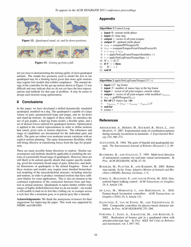
Sit, lie-down, stand, and get-up: Frames from a stand, sit, andlie-down animation are shown in Figure 12. The get-up motionis illustrated in Figure 13. Designing these controllers is currentlydone manually. We expect that more rapid design could be achievedwith a suitable graphical user interface or the use of an optimiza-tion framework similar to that used to develop the other gaits andskills. The motions are robust to minor variations in the initial stateof the quadruped. Larger variations require the use of the walk ortrot controller in order to return the pose to a state that more closelyresembles the initial standing pose used in the design of the con-troller. We have successfully experimented with transitioning fromthe sitting position to the trot gait without passing through an inter-mediate standing pose. Attempts to transition more directly from asitting pose to a canter or transverse gallop were not successful, al-though we expect that it is possible to design such transitions. Thelie down controller remains robust in a trial where the hind feet areon a raised 8 cm block.
Limitations: Our current model makes some significant approxi-mations to the skeletal geometry of a dog. This is particularly ev-ident in the modeling of the scapula, i.e., at the shoulders of ourquadruped model. It is not clear what the ramifications of our sim-plifications are on the gaits and motions that can be achieved. Forsimplicity, the current implementation does not model self colli-sions. The motions of the head and tail are not modeled in detail.While we can can successfully demonstrate turning motions, we are
9
To appear in the ACM SIGGRAPH 2011 conference proceedings
Figure 12: Quadruped stand, sit, and lie-down positions.
Figure 13: Getting up from a fall.
not yet close to demonstrating the turning agility of most quadrupedanimals. The simple box geometry used to model the feet in ourquadruped may be a limiting factor given that more agile motionsmay require foot models that exhibit compliance. The manual de-sign of the controller for the get-up motion shown in Figure 13 wasdifficult and may indicate that we do not yet have the best represe-nations and methods for that type of problem. It may be easier todesign such motions using optimization.
8 Conclusions
In this paper, we have developed a skilled dynamically simulatedquadruped, modeled on a dog. The quadruped is capable of a largevariety of gaits, parameterized leaps and jumps, and sit, lie-downand stand-up motions. In support of these skills, we introduce theuse of gait graphs, a dual leg frame model, a flexible spine, and aset of abstract forces tailored for quadruped motions. Optimizationis applied to the control representation in order to define motionsthat satisfy given style or motion objectives. The robustness andrange of capabilities are documented for the individual gaits andskills. The gaits are robust over moderate terrain variations with noexplicit motion planning. The spine demonstrates flexibility whilestill being effective at transferring forces from the legs for propul-sion.
There are many possible future directions to explore. Similar rep-resentations and methods should be applicable to modeling the mo-tions of a potentially broad range of quadrupeds. However, there arestill likely to be animal-specific details that require specific model-ing, given the extremely broad range of gaits, behaviors, and skele-tal dimensions of quadrupeds in the animal kingdom. Some ofthese motions and models may require more detailed biomechan-ical modeling of the musculoskeletal structure, including musclesand tendons, in order to produce simulated motions that have suffi-cient fidelity for some applications. This is also an element in thecontinued exploration of the connection between form and func-tion in animal anatomy. Quadrupeds in nature further exhibit wideranges of highly skilled behaviors that we do not model – our modelis still unable to land on its feet like a falling cat, to scamper acrossa rock face like a mountain goat, or to pursue prey like a cheetah.
Acknowledgements: We thank the anonymous reviewers for theirsuggestions for improving the paper. This work was supported byNSERC and GRAND.
Appendix
Algorithm 1 Control Loop
1: input Φ: current stride phase2: input dt: time step3: output τ : vector of all joint torques4: output Φ′: updated stride phase5: τPD = computePDTorques(Φ)6: τV F = computeTorquesFromVirtualForces(Φ)7: τ = τPD + τV F
8: τ = applyNetLegFrameTorque(shoulders, τ )9: τ = applyNetLegFrameTorque(hips, τ )
10: Φ′+ = dt/T11: if Φ′ > 1 then12: Φ′− = 113: end if
Algorithm 2 applyNetLegFrameTorque(LF, τ )
1: input LF : leg frame2: input N : number of stance legs in the leg frame3: input τ : vector of all joint torques; current values4: output τ : vector of all joint torques with modified τstancei
5: τLF = getPDTorque(ΩLF )6: for all LF stance leg i do7: τstancei = (τLF − τswing − τspine)/N8: end for9: return τ
References
ABOURACHID, A., HERBIN, M., HACKERT, R., MAES, L., ANDMARTIN, V. 2007. Experimental study of coordination patternsduring unsteady locomotion in mammals. J. Experimental Biol-ogy 210, 366–372.
ALEXANDER, R. 1984. The gaits of bipedal and quadrupedal ani-mals. The International Journal of Robotics Research 3, 2, 49–59.
BLUMBERG, B., AND GALYEAN, T. 1995. Multi-level directionof autonomous creatures for real-time virtual environments. InProc. ACM SIGGRAPH, ACM, 47–54.
BUEHLER, M., PLAYTER, R., AND RAIBERT, M. 2005. Robotsstep outside. In Int. Symp. Adaptive Motion of Animals and Ma-chines (AMAM), Ilmenau, Germany, 1–4.
COROS, S., BEAUDOIN, P., AND VAN DE PANNE, M. 2010. Gen-eralized biped walking control. ACM Transctions on Graphics29, 4, Article 130.
DE LASA, M., MORDATCH, I., AND HERTZMANN, A. 2010.Feature-based locomotion controllers. ACM Transactions onGraphics (TOG) 29, 4, Article 131.
FALOUTSOS, P., VAN DE PANNE, M., AND TERZOPOULOS, D.2001. Composable controllers for physics-based character ani-mation. In Proc. ACM SIGGRAPH, 251–260.
FURUSHO, J., SANO, A., SAKAGUCHI, M., AND KOIZUMI, E.2002. Realization of bounce gait in a quadruped robot witharticular-joint-type legs. In Proc. IEEE Intl Conf on Roboticsand Automation, vol. 1, 697–702.
10

To appear in the ACM SIGGRAPH 2011 conference proceedings
GILLETTE, R. L., AND ANGLE, T. C. 2008. Recent developmentsin canine locomotor analysis: A review. The Veterinary Journal178, 165–176.
GIRARD, M., AND MACIEJEWSKI, A. 1985. Computational mod-eling for the computer animation of legged figures. ACM SIG-GRAPH Computer Graphics 19, 3, 263–270.
HECKER, C., RAABE, B., ENSLOW, R. W., DEWEESE, J., MAY-NARD, J., AND VAN PROOIJEN, K. 2008. Real-time motionretargeting to highly varied user-created morphologies. ACMTrans. on Graphics (Proc. SIGGRAPH) 27, 3.
HERR, H., AND MCMAHON, T. 2001. A galloping horse model.Intl Journal of Robotics Research 20, 1, 26.
HODGINS, J., WOOTEN, W., BROGAN, D., AND O’BRIEN, J.1995. Animating human athletics. In Proc. ACM SIGGRAPH,71–78.
KIMURA, H., FUKUOKA, Y., AND COHEN, A. 2007. Adaptivedynamic walking of a quadruped robot on natural ground basedon biological concepts. Intl Journal of Robotics Research 26, 5,475.
KOHL, N., AND STONE, P. 2004. Policy gradient reinforcementlearning for fast quadrupedal locomotion. In Proc. IEEE IntlConf. on Robotics and Automation, vol. 3, 2619–2624.
KOKKEVIS, E., METAXAS, D., AND BADLER, N. 1995. Au-tonomous Animation and Control of Four-Legged Animals. InProc. Graphics Interface, 10–17.
KOLTER, J., RODGERS, M., AND NG, A. 2008. A control archi-tecture for quadruped locomotion over rough terrain. In Proc.IEEE Intl Conf. on Robotics and Automation, 811–818.
KRASNY, D. P., AND ORIN, D. E. 2004. Generating high-speeddynamic running gaits in a quadruped robot using an evolution-ary search. IEEE Trans. on Systems, Man and Cybernetics 34, 4,1685–1696.
KRASNY, D., AND ORIN, D. 2006. A 3D galloping quadrupedrobot. Climbing and Walking Robots, 467–474.
KRY, P. G., REVERET, L., FAURE, F., AND CANI, M.-P. 2009.Modal locomotion: Animating virtual characters with natural vi-brations. Computer Graphics Forum 28, 2.
LASZLO, J. F., VAN DE PANNE, M., AND FIUME, E. 1996. Limitcycle control and its application to the animation of balancingand walking. In Proc. ACM SIGGRAPH, 155–162.
LEE, Y., KIM, S., AND LEE, J. 2010. Data-driven biped control.ACM Transactions on Graphics (TOG) 29, 4, Article 129.
MARHEFKA, D., ORIN, D., SCHMIEDELER, J., AND WALDRON,K. 2003. Intelligent control of quadruped gallops. IEEE/ASMETrans. on Mechatronics 8, 4, 446–456.
MUICO, U., LEE, Y., POPOVIC, J., AND POPOVIC, Z. 2009.Contact-aware nonlinear control of dynamic characters. ACMTransactions on Graphics (TOG) 28, 3, 1–9.
PAUL, R. 1981. Robot manipulators: mathematics, programming,and control: the computer control of robot manipulators. TheMIT Press.
PLAYTER, R., BUEHLER, M., AND RAIBERT, M. 2006. BigDog.In Proc. of SPIE, vol. 6230, 62302O.
POULAKAKIS, I., SMITH, J., AND BUEHLER, M. 2005. Mod-eling and experiments of untethered quadrupedal running with
a bounding gait: The Scout II robot. Intl Journal of RoboticsResearch 24, 4, 239.
PRATT, J., CHEW, C., TORRES, A., DILWORTH, P., AND PRATT,G. 2001. Virtual model control: An intuitive approach forbipedal locomotion. Int’l J. Robotics Research 20, 2, 129.
RAIBERT, M. H., AND HODGINS, J. K. 1991. Animation of dy-namic legged locomotion. In Proc. ACM SIGGRAPH, 349–358.
RAIBERT, M. H. 1986. Legged Robots That Balance. MIT Press.
RINGROSE, R. 1996. Self-stabilizing running. PhD thesis, MIT.
SKRBA, L., REVERET, L., HETROY, F., CANI, M., ANDO’SULLIVAN, C. 2008. Quadruped animation. Eurographics2008-State of the Art Reports, 1–17.
SOK, K. W., KIM, M., AND LEE, J. 2007. Simulating bipedbehaviors from human motion data. ACM Trans. on Graphics(Proc. SIGGRAPH) 26, 3, Article 107.
SUNADA, C., ARGAEZ, D., DUBOWSKY, S., AND MAVROIDIS,C. 1994. A coordinated jacobian transpose control for mo-bile multi-limbed robotic systems. In Proc. IEEE Int’l Conf. onRobotics and Automation, 1910–1915.
TORKOS, N., AND VAN DE PANNE, M. 1998. Footprint-basedquadruped motion synthesis. In Proc. Graphics Interface, 151–160.
TRET, 2011. Tret - parkour dog from ukraine,http://www.youtube.com/watch?v=pxelh vm0uc.Accessed on January 9, 2011.
TSUJITA, K., TSUCHIYA, K., AND ONAT, A. 2001. Adaptive gaitpattern control of a quadruped locomotion robot. In Proc. IEEEIntelligent Robots and Systems, vol. 4, 2318–2325.
VAN DE PANNE, M. 1996. Parameterized gait synthesis. IEEEComputer Graphics and Applications 16, 2 (March), 40–69.
VAN DEN BOGERT, A., SCHAMHARDT, H., AND CROWE, A.1989. Simulation of quadrupedal locomotion using a rigid bodymodel. Journal of biomechanics 22, 1, 33–41.
WALTER, R. M., AND CARRIER, D. R. 2007. Ground forcesapplied by galloping dogs. The Journal of Experimental Biology210, 208–216.
WAMPLER, K., AND POPOVIC, Z. 2009. Optimal gait and formfor animal locomotion. ACM Transactions on Graphics (TOG)28, 3, 1–8.
WONG, H., AND ORIN, D. 1995. Control of a quadruped standingjump over irregular terrain obstacles. Autonomous Robots 1, 2,111–129.
WU, J., AND POPOVIC, Z. 2010. Terrain-adaptive bipedal loco-motion control. ACM Transactions on Graphics (TOG) 29, 4,Article 72.
YE, Y., AND LIU, C. 2010. Optimal feedback control for char-acter animation using an abstract model. ACM Transactions onGraphics (TOG) 29, 4, Article 74.
YIN, K., LOKEN, K., AND VAN DE PANNE, M. 2007. SIMBI-CON: Simple biped locomotion control. ACM Trans. on Graph-ics (Proc. SIGGRAPH) 26, 3, Article 105.
ZUCKER, M., BAGNELL, J., ATKESON, C., AND KUFFNER, J.2010. An optimization approach to rough terrain locomotion. InProc. IEEE Intl Conf. on Robotics and Automation, 3589–3595.
11