pantone 425c -...
TRANSCRIPT


Pantone 425C
For your nearest Polaris dealer, call 1-800-POLARISor visit www.polarisindustries.comPolaris Sales Inc., 2100 Hwy. 55, Medina, MN 55340Phone 1-888-704-5290Part No. 9922571 Rev 01Printed in USA

WARNING
Read, understand, and follow all of the instructions and safety precautions in this manual and on all product labels.
Failure to follow the safety precautions could result in serious injury or death.
WARNING
The engine exhaust from this product contains chemicals known to the State of California to cause cancer, birth defects or other reproductive harm.

1
WELCOMEThank you for purchasing a Polaris vehicle, and welcome to our world-wide family of Polaris owners. We proudly produce an exciting line of utility and recreational products. • Snowmobiles• All-terrain vehicles (ATVs)• RANGER utility vehicles• Victory motorcyclesWe believe Polaris sets a standard of excellence for all utility and recre-ational vehicles manufactured in the world today. Many years of experi-ence have gone into the engineering, design, and development of your Polaris vehicle, making it the finest machine we’ve ever produced.For safe and enjoyable operation of your vehicle, be sure to follow the instructions and recommendations in this owner’s manual. Your manual contains instructions for minor maintenance, but information about major repairs is outlined in the Polaris Service Manual and should be performed only by a Factory Certified Master Service Dealer (MSD) Technician.Your Polaris dealer knows your vehicle best and is interested in your total satisfaction. Be sure to return to your dealership for all of your ser-vice needs during, and after, the warranty period. We also take great pride in our complete line of apparel, parts and acces-sories, available through our online store at www.purepolaris.com. Have your accessories and clothing delivered right to your door!

2
POLARIS and POLARIS THE WAY OUT are registered trademarks of Polaris Indus-tries Inc.RIDER SELECT is a trademark of Polaris Industries Inc.Copyright 2009 Polaris Sales Inc. All information contained within this publication is based on the latest product information at the time of publication. Due to constant improvements in the design and quality of production components, some minor discrep-ancies may result between the actual vehicle and the information presented in this publi-cation. Depictions and/or procedures in this publication are intended for reference use only. No liability can be accepted for omissions or inaccuracies. Any reprinting or reuse of the depictions and/or procedures contained within, whether whole or in part, is expressly prohibited. Printed in U.S.A.2010 FST IQ Touring Owner’s Manual P/N 9922571

3
TABLE OF CONTENTSIntroduction . . . . . . . . . . . . . . . . . . . . . . . . . . . . 5This section contains helpful information for owners and drivers and illustrates the location of important identification numbers that should be recorded in the owner’s manual.
Safety . . . . . . . . . . . . . . . . . . . . . . . . . . . . . . . . . 8This section describes safe vehicle operation and identifies warning decals and their locations.
Features . . . . . . . . . . . . . . . . . . . . . . . . . . . . . . 28This section identifies the locations of your snowmobile’s controls and features.
The Perfect Fit . . . . . . . . . . . . . . . . . . . . . . . . . 54This section explains how to tailor the suspension and other features for an optimum riding experience.
Pre-Ride Inspections . . . . . . . . . . . . . . . . . . . . 66This section explains procedures that must be performed before riding.
Operation . . . . . . . . . . . . . . . . . . . . . . . . . . . . . 75This section explains proper engine break-in, operation of features and general operating procedures.
Maintenance . . . . . . . . . . . . . . . . . . . . . . . . . . . 89This section defines your role, and your dealer’s role, in your snowmo-bile’s regular maintenance.
Polaris Products. . . . . . . . . . . . . . . . . . . . . . . 141Troubleshooting . . . . . . . . . . . . . . . . . . . . . . . 142Warranty . . . . . . . . . . . . . . . . . . . . . . . . . . . . . 148Maintenance Log . . . . . . . . . . . . . . . . . . . . . . 157Index . . . . . . . . . . . . . . . . . . . . . . . . . . . . . . . . 160

4

5
INTRODUCTIONImportant Notes for Owners and DriversAfter reading this manual, store it in the snowmobile for convenient ref-erence. It should remain with the snowmobile when the snowmobile is sold.Some of the illustrations and photos used in this manual are general rep-resentations. Your model may differ.Follow the maintenance program outlined in this manual. Preventive maintenance ensures that critical components of the snowmobile are inspected by your dealer at specific mileage intervals.You and your dealer must complete the registration form included with your snowmobile and forward it to us. This completed form is necessary to ensure warranty coverage.Protect and preserve your right to ride by joining your local trail riding clubs.When teaching inexperienced operators to ride, set up a predetermined course for practice. Make sure they know how to drive and control the snowmobile before allowing them to make longer trips. Teach them proper snowmobile courtesy, and enroll them in driver’s training and safety courses sponsored by local or state organizations.

6
INTRODUCTIONPreservation of the EnvironmentPolaris is committed to supporting an environmental education cam-paign. We encourage state and provincial governments across the snow-belt to adopt rigorous safety training programs that encourage protection of our environment, including wildlife and vegetation.Snowmobile clubs and other organizations are working together to pro-tect our environment. Please support their efforts and operate your snowmobile with consideration for the protection and preservation of our environment.Noise LevelOne of the most publicized issues about snowmobiles is noise. The Society of Automotive Engineers (SAE), the standard-setting body for snowmobile development, recommends that snowmobiles conform to prescribed sound levels.Polaris snowmobiles are engineered to conform to these SAE standards. Our muffler systems are designed to reduce noise levels and must not be altered or removed. The sound of your snowmobile may not be welcome to non-snowmobilers, so you have a responsibility to operate your snowmobile with concern for others. We do our part by manufacturing quieter snowmobiles; we ask your help to further reduce the impact of noise by operating your snowmobile safely and responsibly.

7
INTRODUCTIONVehicle Identification NumbersRecord your snowmobile’s identification numbers and key number in the spaces provided. Remove the spare key and store it in a safe place. Your key can be duplicated only by mating a Polaris key blank with one of your existing keys, so if both keys are lost, the ignition switch must be replaced.
Vehicle Model Number: ___________________________________________________
Tunnel VIN: ____________________________________________________________(lower right side of the tunnel)
Engine Serial Number (on valve cover): _______________________________________
Key Number: ___________________________________________________________

8
SAFETYOperator SafetyThe following signal words and symbols appear throughout this manual and on your vehicle. Your safety is involved when these words and sym-bols are used. Become familiar with their meanings before reading the manual.
The safety alert symbol indicates a potential personal injury hazard.
WARNINGA WARNING indicates a hazardous situation which, if not avoided, may result in death or serious injury.
CAUTIONA CAUTION indicates a hazardous situation which, if not avoided, may result in minor or moderate injury.
NOTICEA NOTICE indicates a situation that may result in property damage.

9
SAFETYOperator SafetyFollow the recommended maintenance program outlined beginning on page 90 of this manual to ensure that all critical components on the snowmobile are thoroughly inspected by your dealer at specific mileage intervals.
Driving a snowmobile requires your full attention. DO NOT drink alcohol or use drugs or medications before or while driving or riding as a passenger. They will reduce your alertness and slow your reaction time.
Snowmobiles are capable of traveling at high speeds. Use extra caution to ensure operator safety. Make sure your snowmobile is in excellent operating condition at all times. Always check major and vital safety components before every ride.
All Polaris snowmobiles are designed and tested to provide safe operation when used as directed. Failure of critical machine components may result from opera-tion with any modifications, especially those that increase speed or power. DO NOT MODIFY YOUR MACHINE. The snowmobile may become aerodynami-cally unstable at speeds higher than those for which it is designed. Loss of con-trol may occur at higher speeds. Modifications may also create a safety hazard and lead to bodily injury.
The warranty on your entire machine is terminated if any equipment has been added, or any modifications have been made, to increase the speed or power of the snowmobile.
WARNING

10
SAFETYOperator SafetyStay Clear of TrackYour snowmobile is propelled by a revolving track that must be partially exposed for proper operation.WARNING! Serious injuries may result if hands, feet, or clothing become entangled in the track. Be alert when riding, and remain properly seated to stay clear of the track. Never hold the snowmobile up or stand behind it while warming up the track. A loose track or flying debris could cause serious injury or death. We recommend having your dealer perform all track service and alignment procedures.
Stay Clear of EngineNever attempt adjustments with the engine running. Turn off the igni-tion, raise the hood, make the adjustment, secure shields and guards, secure the hood, and then restart the engine to check its operation.WARNING! Serious injury can occur if fingers or clothing contact the moving parts of an engine. Always stop the engine before attempting adjustments.

11
SAFETYOperator SafetyRiding PositionOperating a snowmobile requires skill and balance for proper control. Rider positions may vary with experience; but under many conditions, the proper position is to be seated with both feet on the running boards and both hands on the handlebar grips for proper throttle, brake and steering control.WARNING! Improper riding position may reduce control and could result in serious injury or death. Always ride in a position that allows for control of your vehicle.
Survival PreparationFor your safety, always ride in a group of other snowmobilers. Always tell someone where you’re going and how long you expect to be gone. If it isn’t possible to ride with others, and you must travel into remote areas, always carry survival equipment that’s appropriate to the condi-tions you may encounter. Such equipment may include, but is not lim-ited to: extra clothing, a sleeping bag, a flashlight, food and water, a signaling mirror, a means of building a fire, and a two-way radio or cel-lular telephone.Always carry the owner’s manual on your snowmobile. For added pro-tection, purchase and carry the following items on your snowmobile as well:
• Spare Drive Belt • Winter Survival Kit• Extra Set of Spark Plugs • Trail Map• Tow Rope • First Aid Kit• Extra Oil • Tool Kit• Fuel Deicer

12
SAFETYOperator SafetyRiding ApparelHelmetWearing a helmet can prevent a severe head injury. Whenever riding a Polaris vehicle, always wear a helmet that meets or exceeds established safety standards.Approved helmets in the USA and Canada bear a U.S. Department of Transportation (DOT) label.Approved helmets in Europe, Asia and Oceania bear the ECE 22.05 label. The ECE mark consists of a circle surrounding the letter E, followed by the distinguishing number of the country which has granted approval. The approval number and serial number will also be displayed on the label.Eye ProtectionDo not depend on eyeglasses or sunglasses for eye protection. When-ever riding a Polaris vehicle, always wear shatterproof goggles or use a shatterproof helmet face shield. Polaris recommends wearing approved Personal Protective Equipment (PPE) bearing markings such as VESC 8, V-8, Z87.1, or CE. Make sure protective eye wear is kept clean.ClothingBe prepared, be warm and be com-fortable when riding. Be aware of the weather forecast, especially the windchill, and dress accordingly. See the chart on page 23.WARNING! Avoid wearing loose clothing or long scarves, which can become entangled in moving parts and cause serious injury. Always wear an approved helmet and eye protection.
E4
0510390006.31

13
SAFETYOperator SafetyRider CapacityDriving 1-Up - Some Polaris snowmobiles are designed for a single rider only. A decal on the console of these models indicates single rider operation.Driving 2-Up - Some Polaris snowmobiles are designed for up to two riders. A decal on the hood of these models indicates that the vehicle is designed for one operator and one passenger only.WARNING! Control becomes more difficult with two people on board. More space is required to make turns, and longer distances are needed for stopping. Make sure the passenger remains seated behind the driver, facing forward, with both feet placed firmly on the running boards. Slow down and avoid “jumping” your snowmobile.Snowmobiles designed for two riders should never be operated with more than two people on board. When traveling with a passenger, it’s the driver’s responsibility to operate the snowmobile safely. Slow down! Control becomes more difficult with two people on board. More space is required to make turns, and longer distances are necessary for stopping.

14
SAFETYOperator SafetyDisabled OperatorsSafe operation of this rider-active vehicle requires good judgement and physical skills.WARNING! Operators with cognitive or physical disabilities have an increased risk of loss of control, which could result in serious injury or death. Do not allow disabled persons to operate this vehicle.
Cargo OverloadToo much weight on the rear of the snowmobile may reduce your ability to steer. Do not exceed carrier and rack weight limits, and do not allow a passenger to sit on the seat back or the cargo carrier.

15
SAFETYOperator SafetyExcessive SpeedWARNING! High speed driving, especially at night, could result in serious injury or death. Always reduce speed when driving at night or in inclement weather.Always observe all state and local laws governing snowmobile opera-tion and speed limits. Always be alert and pay attention to the trail ahead. If your speed is 40 MPH (64 km/h), your snowmobile is traveling about 60 feet (18 m) per second. If you look back for only two seconds, your snowmobile will travel about 120 feet (36 m). If your speed is 60 MPH (96 km/h), your snowmobile will travel about 180 feet (55 m) in two seconds.Traveling at night requires extra caution. Check headlight and taillight to ensure proper operation, and don’t over-drive your headlight beam. Always be able to bring your snowmobile to a stop in the distance illu-minated by the headlight.

16
SAFETYOperator SafetyDriver AwarenessSlow down when traveling near poles, posts, or other obstacles. Be especially alert if you’re snowmobiling after dark. Always be on the alert for wire fences. Single strands are especially dangerous, since there may be a great distance between posts. Guy wires on utility poles are also difficult to distinguish.Make sure the way is clear before crossing railroads and other roads and highways. The noise of your snowmobile will drown out the sound of approaching vehicles. Look ahead, behind, and to both sides before turning or crossing railroad tracks or highways. Steep embankments may also hide your view. Always leave yourself a way out.Variances in snow depth and/or water currents may result in uneven ice thickness. Always check with local residents or authorities for general information on conditions when traveling on lakes and streams that are strange to you. Before riding your snowmobile on a frozen body of water, be sure the ice is thick enough to support the snowmobile and its operator, as well as the force created by a moving vehicle. You may drown if you and the snowmobile break through the ice.When teaching inexperienced operators to ride, set up a predetermined course for practice. Make sure they know how to drive and control the snowmobile before allowing them to make longer trips. Teach them proper snowmobile courtesy, and enroll them in driver’s training and safety courses sponsored by local or state organizations.
RR
17
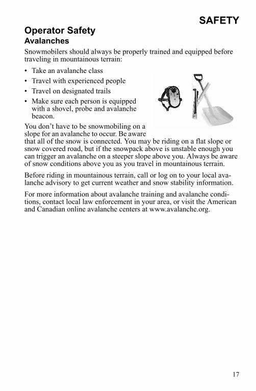
SAFETYOperator SafetyAvalanchesSnowmobilers should always be properly trained and equipped before traveling in mountainous terrain:• Take an avalanche class• Travel with experienced people• Travel on designated trails• Make sure each person is equipped
with a shovel, probe and avalanche beacon.
You don’t have to be snowmobiling on a slope for an avalanche to occur. Be aware that all of the snow is connected. You may be riding on a flat slope or snow covered road, but if the snowpack above is unstable enough you can trigger an avalanche on a steeper slope above you. Always be aware of snow conditions above you as you travel in mountainous terrain.Before riding in mountainous terrain, call or log on to your local ava-lanche advisory to get current weather and snow stability information.For more information about avalanche training and avalanche condi-tions, contact local law enforcement in your area, or visit the American and Canadian online avalanche centers at www.avalanche.org.

18
SAFETYOperator SafetyIce and Snow Build-upWARNING! Ice and snow build-up may interfere with the steering of your snowmobile, resulting in serious injury or death. Keep the underhood area free of snow and ice.Before driving, manually turn the skis to the left and right to be sure ice and snow are not interfering with full left and right steering. If difficulty is encountered, remove ice and snow build-up that may be obstructing the steering linkage.If your snowmobile is equipped with RIDER SELECT, perform this check in both the full up and full down steering positions.Driving DownhillWhen riding downhill, shift your weight to the rear of the snowmobile and reduce your speed to a minimum. Apply just enough throttle to keep the clutch engaged, allowing the engine’s compression to help slow the snowmobile and keep it from rolling freely downhill.WARNING! When driving on long downhill stretches, pump the brakes. Riding the brakes may cause the brake system to overheat, which may result in brake failure. Excessive or repetitive use of the brakes for high speed stops will also cause an overheated brake system. This condition may lead to a sudden loss of brakes and/or fire and may result in serious injury or death.

19
SAFETYOperator SafetyDriving on Slippery SurfacesWARNING! Never attempt an abrupt change of direction when operating on slippery surfaces. Proceed slowly and use extra caution. Driving on ice or hard-packed snow reduces steering and braking control, which may result in loss of control and serious injury or death. Slow down and use extra caution when operating on slippery surfaces.
Driving on SlopesWARNING! Climbing a hill or crossing the face of a slope may result in loss of balance and snowmobile rollover, causing serious injury or death. Use caution and good judgement when driving in hilly terrain.Use extra caution when operating in hilly terrain. If climbing a hill is unavoidable, keep your weight low and forward. If you must cross the face of a slope, keep your weight on the uphill side of the snowmobile to maintain proper balance and avoid possible rollover.Slow down when reaching the crest of a hill. Be prepared to react to obstacles, sharp drops or other people or vehicles that may be on the other side of the hill.If you’re unable to continue up a hill, turn the snowmobile downhill before it loses momentum. If this isn’t possible, spin the track just enough to dig in to prevent it from rolling back down the hill. Stop the engine and set the parking brake (if equipped). Keeping away from the downhill side of the snowmobile, pull the rear of the snowmobile around and point the front end and skis downhill. Remount the snowmo-bile, restart the engine, release the parking brake, and descend the hill carefully.

20
SAFETYOperator SafetyDrive BeltDo not operate the engine with the drive belt removed.Any servicing that requires operation without a belt must be performed by your dealer. CAUTION! Operation of the engine with the belt removed may result in personal injury or damage to the engine.
Intake SilencerDo not operate the engine with the intake silencer or filter removed.NOTICE: Damage to the engine may occur if the intake silencer or filter are
removed.
ClutchesDo not attempt to service the clutches.All clutch service must be performed by your dealer. The clutch is a complex mechanism that rotates at high speeds. Each clutch is dynami-cally balanced before installation. Any tampering may disrupt this preci-sion balancing and create an unstable condition.
Cold Weather Drive-AwayWhenever your snowmobile has been parked for a length of time, espe-cially overnight, always make sure the skis and track are loosened from ice and snow before attempting to drive. Apply the throttle with enough authority to put the snowmobile into motion, but always operate within safety limits and, on 2-up snowmobiles, with respect for a passenger.
ManeuverabilityWhile much control and maneuverability is achieved through the steer-ing system and skis, maximum control is achieved by the shifting of your body weight. Maneuverability will change for lighter operators or snowmobiles designed to carry a load or a passenger.

21
SAFETYOperator SafetyInadequate Snow ConditionsSince snow provides the only lubrication for the power slide suspension and, on liquid cooled models, cooling for the engine, adequate snow cover is a requirement for operation of your snowmobile. NOTICE: Driving in too little snow will result in excessive wear and damage to
the slide rail, track and/or engine.WARNING! Inadequate cooling and lubrication will lead to overheating of the slide rail and track, causing premature wear, damage and failure, which can result in serious injury. Reduce speeds and frequently drive into fresh snow to allow adequate cooling and polishing of the slide rail and track surfaces. Avoid operating for prolonged periods on ice, hard-packed surfaces or roads.
Operating in Deep SnowIf the snowmobile becomes stuck in snow, clear the running board area of snow, then step down the snow in front of the snowmobile so that when the throttle is opened, the snowmobile will be able to climb up and over the snow.

22
SAFETYOperator SafetyDriving ResponsiblyEvery snowmobile handles differently, and even the most docile condi-tions may become dangerous if operators drive improperly. If you’re new to snowmobiling, acquaint yourself with the snowmobile and with what it will and won’t do under various conditions. Even seasoned driv-ers should spend some time getting the feel for a snowmobile before attempting ambitious maneuvers.• A snowmobile depends on the rider’s body position for proper bal-
ance in executing turns, traversing hills, etc. Always start on a smooth, level area to begin building your operating experience.
• Before allowing someone else to use your snowmobile, know the extent of their operating skills. Check to see if they’ve taken a snow-mobile safety course and have an operator’s certificate. For their pro-tection, as well as yours, make sure they take a snowmobile safety course. Everyone can benefit from the course.
• Don't "jump" your snowmobile over large drifts or similar terrain. Jumping may injure your back because of spinal compression that could occur when the snowmobile impacts the ground. The seat and suspension of your snowmobile have been designed to provide pro-tection under normal riding conditions. Your snowmobile is not intended for this kind of use.
• Be courteous to oncoming traffic by dimming your headlights and reducing your speed.
• When traveling in a group of snowmobiles, don’t tailgate (follow too closely). Leave enough distance between snowmobiles to provide ample stopping room and to provide protection from flying snow and debris. Allow even more distance when driving on slippery surfaces or when driving in darkness or other low visibility conditions. Be aware of any snowmobile traffic around your vehicle. Drive defen-sively to avoid accidents.
• Remove the key from the ignition when you leave the snowmobile unattended.

23
SAFETYOperator SafetyWindchill/Temperature ChartsThe following information is provided to help you determine when tem-peratures become dangerous for riding.WIND CHILL CHART (°F)
WIND CHILL CHART (°C)
Wind Speed
in MPH
Actual Thermometer Reading (_F)40 35 30 25 20 15 10 5 0 -5 -10 -15 -20 -25 -30 -35 -40 -45
Equivalent Temperature (_F)Calm 40 35 30 25 20 15 10 5 0 -5 -10 -15 -20 -25 -30 -35 -40 -45
5 36 31 25 19 13 7 1 -5 -11 -16 -22 -28 -34 -40 -46 -52 -57 -6310 34 27 21 15 9 3 -4 -10 -16 -22 -28 -35 -41 -47 -53 -59 -66 -7215 32 25 19 13 6 0 -7 -13 -19 -26 -32 -39 -45 -51 -58 -64 -71 -7720 30 24 17 11 4 -2 -9 -15 -22 -29 -35 -42 -48 -55 -61 -68 -74 -8125 29 23 16 9 3 -4 -11 -17 -24 -31 -37 -44 -51 -58 -64 -71 -78 -8430 28 22 15 8 1 -5 -12 -19 -26 -33 -39 -46 -53 -60 -67 -73 -80 -8735 28 21 14 7 0 -7 -14 -21 -27 -34 -41 -48 -55 -62 -69 -76 -82 -8940 27 20 13 6 -1 -8 -15 -22 -29 -36 -43 -50 -57 -64 -71 -78 -84 -9145 26 19 12 5 -2 -9 -16 -23 -30 -37 -44 -51 -58 -65 -72 -79 -86 -9350 26 19 12 4 -3 -10 -17 -24 -31 -38 -45 -52 -60 -67 -74 -81 -88 -9555 25 18 11 4 -3 -11 -18 -25 -32 -39 -46 -54 -61 -68 -75 -82 -89 -9760 25 17 10 3 -4 -11 -19 -26 -33 -40 -48 -55 -62 -69 -76 -84 -91 -98
Frostbite in >> 30 min. 10 min. 5 min.
Wind Speed
in KPH
Actual Thermometer Reading (_C)5 2 -1 -4 -7 -10 -13 -16 -19 -22 -25 -28 -31 -34 -37 -40 -43 -46
Equivalent Temperature (_C)Calm 5 2 -1 -4 -7 -10 -13 -16 -19 -22 -25 -28 -31 -34 -37 -40 -43 -46
8 3 0 -4 -7 -11 -14 -18 -22 -25 -29 -32 -36 -39 -43 -46 -50 -53 -5716 2 -2 -6 -10 -13 -17 -21 -24 -28 -32 -36 -39 -43 -47 -50 -54 -58 -6224 1 -3 -7 -11 -15 -19 -22 -26 -30 -34 -38 -42 -45 -49 -53 -57 -61 -6532 0 -4 -8 -12 -16 -20 -24 -28 -32 -36 -39 -43 -47 -51 -55 -59 -63 -6740 -1 -5 -9 -13 -17 -21 -25 -29 -33 -37 -41 -45 -49 -53 -57 -61 -65 -6948 -1 -5 -9 -13 -18 -22 -26 -30 -34 -38 -42 -46 -50 -54 -58 -62 -66 -7056 -2 -6 -10 -14 -18 -22 -26 -31 -35 -39 -43 -47 -51 -55 -59 -64 -68 -7264 -2 -6 -10 -15 -19 -23 -27 -31 -35 -40 -44 -48 -52 -56 -61 -65 -69 -7372 -2 -7 -11 -15 -19 -23 -28 -32 -36 -40 -45 -49 -53 -57 -61 -66 -70 -7480 -3 -7 -11 -15 -20 -24 -28 -33 -37 -41 -45 -50 -54 -58 -62 -67 -71 -7588 -3 -7 -12 -16 -20 -24 -29 -33 -37 -42 -46 -50 -55 -59 -63 -67 -72 -7696 -3 -8 -12 -16 -21 -25 -29 -34 -38 -42 -47 -51 -55 -60 -64 -68 -73 -77
Frostbite in >> 30 min. 10 min. 5 min.

24
SAFETYSafety Decals and LocationsWarning decals have been placed on the snowmobile for your protec-tion. Read and follow the instructions of the decals and other warnings on the snowmobile carefully. If any of the decals depicted in this manual differ from the decals on your snowmobile, always read and follow the instructions of the decals on the snowmobile.If any decal becomes illegible or comes off, contact your Polaris dealer to purchase a replacement. Replacement safety decals are provided by Polaris at no charge. The part number is printed on the decal.
Clutch Cover WarningThis warning decal is found under the hood on the clutch cover:
WARNINGDo not operate with hood open.Do not attempt adjustment with engine running.Do not operate engine with plenum/belt guard removed.Never run engine with drive belt removed.Never service clutches yourself. See your dealer.
Pressure Cap WarningThis warning decal is found under the hood on the pressure cap of appli-cable liquid cooled models:
WARNINGDo not open hot. Test or replace when changing coolant. Press down and turn to release cap. 13 PSI

25
SAFETYSafety Decals and Locations“No Passenger” WarningSnowmobiles designed for a single rider only have a warning decal on the left console:
WARNINGThis vehicle is designed for operator only.“NO PASSENGER”
Passenger WarningSnowmobiles designed for an operator and one passenger have a warning decal on the left console. For more information on operating with a passenger, see page 13.
WARNINGThis vehicle is designed for operator and “ONE” passenger only.
Track WarningWARNINGStay clear of track. Do not sit on seat back. Entanglement with the track or a fall from seat back may result in severe injury or death.
“No Passenger” Warning or
“One Passenger” Warning
Track Warning

26
SAFETYSafety Decals and Locations
Reverse WarningPolaris snowmobiles equipped with electric reverse and will have this decal on the console:
WARNINGReverse operation, even at low speeds, can cause loss of control resulting in serious injury or death. To avoid loss of control, always:• Look behind before and while backing up.• Avoid sharp turns.• Shift to or from reverse only when stopped.• Apply throttle slowly.NOTE: For more information, see Owner's Manual.If electric reverse:• Machine stopped and engine at idle, push yellow button on LH con-
trol to reverse. Flashing light on dash indicates reverse operation.• Push button again to return to forward.
Reverse Warning
Operation Warning

27
SAFETYSafety Decals and LocationsOperation WarningAn operation warning decal is present on the console of all Polaris snowmobiles:
WARNING• To avoid serious injury or death, read and understand all warnings
and the Owner’s Manual before operation. If manual is missing, con-tact a Polaris dealer for a replacement.
• This vehicle is capable of high speeds. Buried objects or uneven terrain can cause loss of control. Reduce speed and use extreme caution when operating in unfamiliar terrain.
• Excessive speed, especially at night or with limited visibility, can result in insufficient time for you to react to terrain changes, to avoid unexpected obstacles, or to stop safely.
• Never consume alcohol or drugs before or while operating this vehi-cle.
• In an emergency, push down the Auxiliary Shut-Off Switch, located on the top of the throttle control assembly, to stop the engine. Then pull the brake lever to stop.
• Always wear an approved helmet, eye protection, and adequate clothing while operating this vehicle.
• This vehicle is designed for adult use only. Check local laws for age requirements.
• When operating with a passenger (on approved models only), reduce speed and allow extra space for steering and stopping. A passenger reduces your ability to control the vehicle.
• When operating on hard-packed snow, ice, or when crossing roads, steering and braking ability are greatly reduced. Reduce speed and allow extra space to turn or stop.
• To maintain vehicle control on ice or hard-packed surfaces, you should have a proper balance of ski carbides to track studs. See Owner’s Manual for proper use of traction products.
• Repeated stops from high speed may cause fading or sudden loss of braking ability.
• Parking brake may relax when used for long periods. Do not leave brake engaged for more than five minutes.
• Before starting the engine, check throttle, brake, and steering for proper operation. Make sure hood is latched. Be seated and in posi-tion to control the vehicle.
Oil injection system: Use unmixed fuel only. Check oil level when refueling.

28
FEATURES
1. Nosepan2. Skis3. Front Bumper (do not use for pulling or dragging the snowmobile)4. Hood5. Headlight6. Windshield7. Operator Seat8. Passenger Seat9. Backrest10. Passenger Grab Handle11. Cargo Bag12. Grab Handle Heater Switch13. Taillights14. Rear Bumper15. Snow Flap16. Track17. Suspension
3
4
5
6
2
1
7
89
12
13
14
15
1617
1011

29
FEATURES1. MFD Display2. Mirrors3. Rider Selectt4. Fuel Filler Cap5. Handlebar6. Hood Hold Down
Straps7. Handlebar Grip Warmer
Switch8. Thumbwarmer Switch9. Electronic Reverse
Button10. MFD Control11. Headlight Dimmer
Switch12. Parking Brake Lock13. Brake Lever14. Engine Stop Switch15. Throttle Control16. Ignition Switch
16
1
13
14 15
12
78
9
1011
3
1
6
4 5

30
FEATURESBackrestThe backrest is adjustable for either operator or passenger use.1. Loosen the upper adjustment
knobs to raise or lower the backrest.
2. Loosen the lower adjustment knobs to move the backrest for-ward for operator use or rear-ward for passenger use.
3. Always tighten the knobs securely after adjusting.
Adjustable HeadlightsMove the adjuster to the left to lower the headlight beam.Move the adjuster to the right to raise the headlight beam.
Radiator Compartment Access PanelThe access panel is provided for cleaning debris from the radiator.
Operator/Passenger
Raise/Lower

31
FEATURESCargo BagThe cargo bag is secured to the rear of the tunnel with straps. The cargo bag and the passenger seat are removable to provide open storage for transporting larger items. The maximum weight capacity for the cargo area is 30 lbs. (14 kg). Always secure cargo before operating. Do not exceed the weight limit. Do not allow a passenger to sit on the seat back or the cargo area.1. Push down on the seat latch lever,
which is located at the lower rear of the passenger seat.
2. Lift up the seat and remove it from the chassis.
3. Reverse the procedure to reinstall the seat. Press down firmly on both sides of the seat to engage the latch. Verify that the latch is engaged by firmly pulling the seat upward.
Cargo Bag
Seat Latch

32
FEATURESPassenger Grab HandleOn some models the position of the passenger grab handles can be adjusted for rider preference.1. Unscrew and remove the knob
assemblies that secure the grab handles.
2. Reposition the grab handles to one of the three available posi-tions on the grab handle tube between the operator seat and the passenger seat.
3. Reinstall the knob assemblies and tighten securely.
KnobAssembly

33
FEATURES12-Volt DC OutletIf equipped, use the outlet to power a global positioning sensor (GPS), heated helmet shield, utility light, cell phone or other accessories.The 12-volt DC outlet is installed in the recoil pocket next to the right hood hold-down. If you install an accessory outlet on your model, always install it in the recoil pocket. The fuel filter is installed in the upper console area. Do not install an outlet on the upper console.WARNING! Serious injury could occur if sparks ignite a fuel supply. Do not install an accessory 12-volt DC outlet on the upper console. Install the outlet in the recoil pocket.
12-Volt DC Outlet

34
FEATURESRIDER SELECT Adjustable Steering SystemThe RIDER SELECT adjustable steering system (if equipped) allows you to adjust the handlebar position to fit your style of riding. Some models have five (5) adjustment positions. Other models have seven (7) positions.WARNING! If your snowmobile has five adjustment positions, do not remove the RIDER SELECT lockout. Your Polaris snowmobile has been engineered for this range of adjustability. Removing this lockout and using RIDER SELECT position 6 or 7 will result in the handlebars and brake lever contacting other components and interfering with steering and braking. This could lead to loss of control resulting in serious injury or death. Always be sure that the handlebars and brake lever do not contact any other snowmobile components at any steering position AND at any RIDER SELECT position.
Do not use RIDER SELECT positions 6 or 7 unless riding conditions require it. Operation in position 6 or 7 can reduce vehicle handling for other types of riding and result in serious injury or death.

35
FEATURESRIDER SELECT Adjustable Steering SystemChoosing the Best RIDER SELECT Position
Position Riding Style123
Relaxed Trail RidingRider weight is slightly behind the center of the snowmobile for comfortable and relaxed riding.
45
General Trail Riding, Boondocking, Deep Snow RidingRider weight is centered on the snowmo-bile, providing balance, comfort and con-trol for both novice and experienced riders. This is the recommended position for most riding situations.
67
Snowcross/Steep Hill Climbing Only Rider weight is ahead of the center of the snowmobile, adding weight to the skis and making the snowmobile heavier in the front. These positions are ONLY for snowcross and severe hill climbing.

36
FEATURESRIDER SELECT Adjustable Steering SystemWARNING! Attempting to adjust the handlebar position while the snowmobile is moving could result in loss of control and serious injury or death. Always stop the snowmobile before attempting to adjust the steering system.
1. Stop the snowmobile.2. Press the release button
and move the handlebar forward or rearward to the desired position.
WARNING! Do not lubricate the RIDER SELECT mechanism. Doing so could cause loss of control and result in serious injury or death. The RIDER SELECT mechanism is lubricated for life at the factory.WARNING! Some aftermarket accessories (including windshields and cargo bags) may interfere with the handlebar. Such accessories could limit your ability to steer the vehicle and/or may contact the brake lever. This could lead to loss of control resulting in serious injury or death. Always be sure that accessories do not contact the handlebar or brake lever at any steering position and at any RIDER SELECT position.

37
FEATURESEngine Management SystemMalfunction Indicator Lamp (MIL)Illuminated MILThe MIL (Check Engine Indicator) will illuminate when a problem with engine management system components is detected.1. Turn the engine off and restart it. If the light goes off, continued
operation is permissible.2. If the light illuminates again, determine whether engine RPM or
vehicle speed is limited, then check the charts on page 38 to identify the cause. If you are unable to determine the cause of an illuminated MIL, please see your Polaris dealer.
Flashing MIL (Turbo)The MIL will flash if an error with the turbo boost regulation system is detected.NOTICE: If you are unable to determine and correct the cause of a flashing MIL
or high temperature indicator, serious engine damage may occur with continued operation. See your Polaris dealer.
1. Verify that all electrical connections are secure.2. Check battery voltage on the gauge, and install a new battery if volt-
age is low (see page 52). 3. Verify that engine temperature is within the recommended operating
range. See the Turbo Boost chart on page 38.A flashing MIL may also be caused by damaged or disconnected hoses between the turbocharger and wastegate solenoid pulse valve (located on the engine side of the airbox) or between the wastegate actuator (located under the turbocharger) and wastegate solenoid pulse valve. If the hose has no damage and is not disconnected, see your dealer imme-diately.NOTICE: Serious engine damage may occur if the wastegate reference line is
removed or modified. DO NOT remove or modify the wastegate reference line.

38
FEATURESEngine Management SystemTo protect the engine, the engine management system will limit engine RPM, vehicle speed or turbo boost (if equipped) if the following condi-tions are encountered. Under extreme overheating conditions, the sys-tem will also stop the engine entirely to prevent engine damage.
Vehicle Speed is Limited
Engine Speed is Limited
Turbo Boost is Limited (Turbo)
Cause Function Maximum SpeedMPH (km/h)
Result
Reverse is selected Reverse 12 (19)Engine will mis-fire at higher vehicle speed
Defective rollover switch Rollover 37 (59)
Throttle stuck, throttle lever depressed
Throttle stuck, throttle safety switch high
18 (29)
Maximum vehicle speed Max speed limiter 186 (299)
Cause Function Maximum RPM Result
Reverse is selected, speed sensor error
Reverse 5300
Engine will mis-fire at higher engine speed
Defective rollover switch, speed sensor error
Rollover 6000
Throttle stuck, throttle lever depressed, speed sensor error
Throttle stuck, throttle safety switch high
5450
Throttle stuck, throttle lever at idle position
Throttle stuck, throttle safety switch low
2400
Maximum vehicle speed, speed sensor error
Max speed limiter 8800
Reverse failure Reverse 2500 ECU cannot determine if reverse or for-ward selected
Indication Result
Illuminated High Temperature Indicator
Operator may feel loss of power
Engine coolant temperature is at or below 122° F (50° C) OREngine coolant temperature is at or above 203° F (95° C)
Intake manifold air temperature is at or below 32° F (0° C) ORIntake manifold air temperature is at or above 158° F (70° C)
Overboost condition occurs (Check Engine light will flash)
Fuel octane is too low (use the recommended fuel)

39
FEATURESEngine Management SystemThe engine management system is programmed to alert the rider when coolant temperatures reach higher-than-normal levels. The system responds by taking the following sequential steps to alert the rider.1. The High Temperature Indicator on the MFD will flash.To cool the engine, drive the snowmobile into soft snow so that it comes into contact with the heat exchangers on the snowmobile. Alternately, you can stop the snowmobile and pack snow or ice onto the heat exchangers to bring the temperature of the engine down.2. The High Temperature Indicator on the MFD will flash and the
engine will misfire or "stutter".If you do not notice the flashing indicator on the MFD or do not suffi-ciently cool the snowmobile, the engine will misfire to alert you to look at the MFD and take action. Again, driving the snowmobile into soft snow or packing snow onto the heat exchangers should cool the engine.3. The engine will stop.If the engine reaches an extreme temperature where damage becomes possible, the system will stop the engine. This condition will occur only after the system has taken both previous steps to alert the rider to the extreme engine temperature. If the engine stops and you attempt to restart it while before it has cooled sufficiently, the engine will restart and run for two seconds but will immediately stop again.The engine management system will also turn the engine off if the engine reaches an extreme temperature while idling.

40
FEATURESKnock Sensor (Turbo Models)A knock sensor monitors the engine and responds to detonation by auto-matically reducing the engine timing and adding fuel. This results in decreased engine RPM and performance.Engine performance will be reduced if fuel with a lower octane than 91 is used. See fuel recommendations on page 81.EffectThe knock sensor system prevents damage to the engine from detona-tion while developing the maximum power of the engine safely. If the system senses detonation beyond a preset limit, it retards ignition timing and adds fuel to reduce the detonation and prevent engine damage.When the detonation returns to a permissible level, the system will return spark and fuel to normal, allowing the engine to run at rated power levels.Fail-SafeThe knock sensor includes a sensor fail-safe system to prevent the engine from damage if the sensor fails, becomes disconnected or is unable to detect detonation. The rider will experience a loss in power. The sensor must be reconnected or repaired to regain full power.The check engine light will illuminate if the sensor fails or becomes dis-connected.

41
FEATURESInstrumentationMFD Component Identification
Digital Display Identification
Item
1 Analog Gauge
2 Digital Gauge
3 Check Engine Indicator
4 High Temp Indicator
5 Brake Indicator
6 Reverse Indicator
7 High Beam Indicator
Item
1 RPM or SpeedAltitude (if equipped)Service Interval
2 Electrical System Voltage Level
3 MAX - Maximum MPH/KPH or RPM
MPH - Miles per hourKPH - Kilometers per hourRPM - Engine crankshaft
revolutions perminute
4 Air Temp (if equipped)Engine TempDegrees CelsiusDegrees Fahrenheit
5 Miles/Kilometers
6 HoursTrip 1/Trip 2/Trip F Service LabelAltitude Label
7 Fuel Level (FS) or Turbo Boost (Turbo models)
12
3
4 5 67
1 2
34
5 6 7

42
FEATURESInstrumentationMFD SettingsThe MFD control switch allows you to set the MFD display to your pref-erences. The rocker switch has a MODE button (top) and a SET but-ton (bottom). Specific instructions are outlined on the following pages.MFD settings can be made with the engine running or with the engine off. If the engine is off, make sure the stop switch is pressed down, and turn the ignition key to the START position briefly to activate the gauge. The gauge will illuminate for about 90 seconds.Standard vs. MetricThe MFD will display either standard or metric units of measurement. While viewing a screen that displays measurements (MPH, km/h or temperatures), press and hold the MODE switch until the unit of mea-surement changes (about 10 seconds).
MFD Control Switch
SET
MODE

43
FEATURESInstrumentationMFD SettingsSpeedometer/TachometerThe speedometer and tachometer can be viewed in either the analog or the digital display. If the analog display is set to show speedometer read-ings, the digital screen will automatically display the tachometer (option 1). If the analog is set to show the tachometer, the digital screen will show the speedometer (option 2).To change viewing preferences, press and hold the MODE button for three seconds. When the button is released, the new setting becomes active and screen colors change. See table below.
Option AnalogDisplay
DigitalDisplay
AnalogScreen
DigitalScreen
1 Speed RPM Blue “MPH” BlueBacklight
2 RPM Speed Red “X100RPM”
RedBacklight

44
FEATURESInstrumentationMFD Digital Display ProgramsPress and release the MODE button to cycle through the three MFD pro-grams: Performance, Engine and History. Each program remains active until you cycle to the next program. While any program is active, press and release the SET button to cycle through the program’s screens.Performance ProgramPress and release the MODE button until the performance program screen is active. The default display for this screen includes electrical system voltage, fuel level (if equipped) and either speed or tachometer, whichever is selected. See page 43. Press and release the SET button to cycle through the following screens: odometer, trip 1 odometer, trip 2 odometer, fuel trip odometer (if fuel is low) and clock (if equipped). Use the following procedures to make changes to these screens.Odometer SettingThe odometer records the vehicle's total distance traveled since manufacture. The odometer cannot be reset.
Trip SettingsTrip 1 and Trip 2 are odometers used to check fuel mileage or to keep track of distance traveled. Both odometers can be reset to zero. 1. Enter the Performance Program.2. Press and release the SET button
until the desired trip screen is active.
3. Press and hold the SET button for two seconds to reset the trip odometer to zero.
4. Press and release the SET button to cycle through additional screens.
45
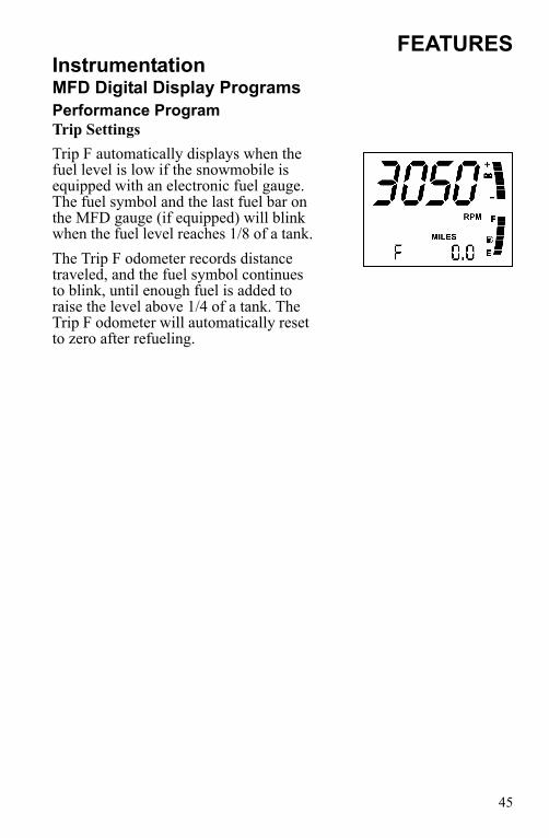
FEATURESInstrumentationMFD Digital Display ProgramsPerformance ProgramTrip SettingsTrip F automatically displays when the fuel level is low if the snowmobile is equipped with an electronic fuel gauge. The fuel symbol and the last fuel bar on the MFD gauge (if equipped) will blink when the fuel level reaches 1/8 of a tank.The Trip F odometer records distance traveled, and the fuel symbol continues to blink, until enough fuel is added to raise the level above 1/4 of a tank. The Trip F odometer will automatically reset to zero after refueling.

46
FEATURESInstrumentationMFD Digital Display ProgramsPerformance ProgramClock Setting (if equipped)1. Enter the Performance Program.2. Press and release the SET button
until the clock screen is active.3. Press and hold the SET button for
five seconds.4. When the hour starts flashing,
press the SET switch once to advance one hour. (Press and hold the SET button to advance the hours quickly.)
5. Press and release the MODE button to save the hour. The minutes will begin flashing.
6. Set the minutes in the same manner.7. When finished, press and release the MODE button to save the new
setting. If the MODE button is not pressed within ten seconds, the gauge will automatically save the new entry.

47
FEATURESInstrumentationMFD Digital Display ProgramsEngine ProgramPress and release the MODE button until the engine program screen is active. The default display for this screen includes engine hours, electri-cal system voltage level, fuel level (if equipped) and either engine cool-ant temperature, air temperature (accessory) or altimeter (accessory).Press and release the SET button to cycle through the following screens: hour meter, engine temperature, air temperature (available as an acces-sory), altimeter (available as an accessory) and turbo boost (if equipped).Hour MeterThe hour meter records the total hours of engine operation since manufacture. This meter cannot be reset.Engine TemperatureA thermometer measures water temperature, giving an indication of engine temperature.Air Temperature (if equipped)The MFD displays actual air temperature in either standard or metric units.1. Enter the Engine Program.2. Press and hold the MODE switch for ten
seconds to switch between standard and metric units of measurement.
48
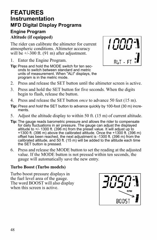
FEATURESInstrumentationMFD Digital Display ProgramsEngine ProgramAltitude (if equipped)The rider can calibrate the altimeter for current atmospheric conditions. Altimeter accuracy will be +/-300 ft. (91 m) after adjustment.1. Enter the Engine Program.Tip: Press and hold the MODE switch for ten sec-
onds to switch between standard and metric units of measurement. When "ALt" displays, the program is in the metric mode.
2. Press and release the SET button until the altimeter screen is active.3. Press and hold the SET button for five seconds. When the digits
begin to flash, release the button. 4. Press and release the SET button once to advance 50 feet (15 m).Tip: Press and hold the SET button to advance quickly by 100-foot (30 m) incre-
ments.5. Adjust the altitude display to within 50 ft. (15 m) of current altitude.Tip: The gauge reads barometric pressure and allows the rider to compensate
for daily fluctuations in air pressure. The gauge can adjust the displayed altitude to +/- 1300 ft. (396 m) from the preset value. It will adjust up to +1300 ft. (396 m) above the calibrated altitude. Once the +1300 ft. (396 m) offset has been reached, the next adjustment is -1300 ft. (396 m) from the calibrated altitude, and 50 ft. (15 m) will be added to the altitude each time the SET button is pressed.
6. Press and release the MODE button to set the reading at the adjusted value. If the MODE button is not pressed within ten seconds, the gauge will automatically save the new entry.
Turbo Boost (Turbo models)Turbo boost pressure displays in the fuel level area of the gauge. The word BOOST will also display when this screen is active.

49
FEATURESInstrumentationMFD Digital Display ProgramsHistory ProgramPress and release the MODE button until the history program screen is active. This screen will always display electrical system voltage level and fuel level (if equipped).Press and release the SET button to cycle through the Maximum Vehicle Speed, Maximum Engine RPM and Service Interval Reminder screens.Maximum Speed/Maximum RPMThe gauge automatically logs the maximum speed and engine RPM even if the history program is not active in the display.1. Enter the History Program.2. Press and release the SET button until
one of the two screens is active.Tip: The MPH and RPM values are both reset at
the same time. Reset the values before each run to obtain accurate readings.
3. Press and hold the SET button for three seconds to reset the recorded maximum values for both MPH and RPM.
Tip: Due to electrical noise, the MFD may occa-sionally display MAX MPH/RPM values that are not representative of actual values.

50
FEATURESInstrumentationMFD Digital Display ProgramsHistory ProgramService Interval ReminderThe gauge logs the number of engine hours accumulated between service reminders. When the logged hours reaches the designated service interval (set by the user), the gauge provides a reminder that service is due. "SErVCE" will flash in the odometer area and "ENG" will flash in the icon area for five seconds each time the engine is started (until the service reminder is reset.) Use the following procedures to reset the reminder.To reset the reminder at the existing interval:1. Enter the History Program.2. Press and release the SET button until the service interval screen is
active.3. Press and hold the SET button for ten seconds, continuing to hold
even after the display begins to flash.4. When the display stops flashing, release the button. The service
interval has been reset.
51
FEATURESInstrumentationMFD Digital Display ProgramsHistory ProgramService Interval ReminderTo reset the reminder at a new interval:1. Enter the History Program.2. Press and release the SET button until the service interval screen is
active.3. Press and hold the SET button for five seconds, until the hours begin
to flash. Immediately release the button.4. Press the button again, up to five times, to advance the reminder in
50-hour increments.Tip: The maximum interval is 250 hours.5. Press and release the MODE button to save the new settings.To disable the service interval reminder:1. Press the SET button once after reaching 250 hours on the display.
The gauge will display "OFF".

52
FEATURESInstrumentationMFD Battery ReplacementModels equipped with the clock feature have a battery to power the clock. If the clock function of the MFD isn't working properly, replace the battery. Replace-ment batteries are available from your dealer.1. Remove the plenum from the under-
side of the hood.2. Locate the black battery compart-
ment. It has a red wire and a brown wire with a white stripe. It's located about three inches down the main harness from the point where the harness connects to the MFD.
3. Cut the plastic cable tie from the outside of the compartment.
4. Carefully cut the bottom of the compartment (opposite the wires) to separate the heat-sealed seams. Squeeze the corners of the compart-ment inward so the battery is visible.
Tip: Note the orientation of the battery before removing it. An incorrectly installed battery will not maintain the clock.

53
FEATURESInstrumentationMFD Battery Replacement5. Using needle-nose pliers, grasp the battery and rotate it so the lead-
ing edge of the battery is raised away from the battery holder. Pull the battery out gently.
Tip: The battery will not come out of the holder unless the leading edge of the battery is raised. Hold the battery compartment, not the wires, while remov-ing the battery. Pulling on the wires will separate them from the battery holder.
6. Install a new battery with fingers only.7. Seal the end of the battery compartment using high strength double-
sided tape between the two compartment halves or high strength single-sided tape around the outside of the compartment.
8. Make sure the taped seam of the compartment faces the downward side of the wire harness.
9. Install a cable tie to secure the compartment to the wire harness in the same location where the previous cable tie was located. Make sure the battery wires are not stretched tight.
Gauge Cleaning1. Wipe the gauge face as needed using a clean cloth and a mild soap
and water solution. Wipe dry with clean, soft cloth.2. Clean the back side of the gauge using a clean cloth and a mild soap
and water solution. Do not remove the electrical connectors or pro-tective rubber boot. Do not spray the back side of the gauge or the wire harness with a pressure washer or other water source.
NOTICE: To prevent damage to the lens, do not use alcohol for cleaning. Do not allow chemicals or sprays to come into contact with the lens. Immediately clean off any gasoline that splashes on the gauge during refueling.
54
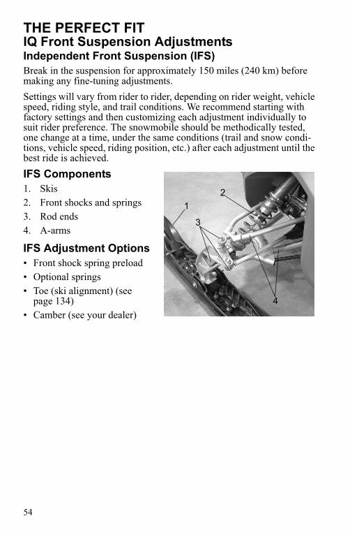
THE PERFECT FITIQ Front Suspension AdjustmentsIndependent Front Suspension (IFS)Break in the suspension for approximately 150 miles (240 km) before making any fine-tuning adjustments.Settings will vary from rider to rider, depending on rider weight, vehicle speed, riding style, and trail conditions. We recommend starting with factory settings and then customizing each adjustment individually to suit rider preference. The snowmobile should be methodically tested, one change at a time, under the same conditions (trail and snow condi-tions, vehicle speed, riding position, etc.) after each adjustment until the best ride is achieved. IFS Components1. Skis2. Front shocks and springs3. Rod ends4. A-arms
IFS Adjustment Options• Front shock spring preload• Optional springs• Toe (ski alignment) (see
page 134)• Camber (see your dealer)
12
3
4

55
THE PERFECT FITIQ Front Suspension AdjustmentsFront Shock Spring PreloadThe factory preload setting should be appropriate for most riders and conditions. Please see your Polaris dealer for assistance before attempt-ing to adjust preload.Increasing the spring preload too much may adversely affect the han-dling of the snowmobile and the performance of the rear suspension.Decreasing the spring preload too much may allow the lower spring retainer to fall off.
56
THE PERFECT FITIQ Front Suspension AdjustmentsShock ValvingThe shocks can be revalved if spring preload alone isn't sufficient and further adjustment is desired to control suspension stiffness.WARNING! Changing shock valving requires special tools and a sound knowledge of mechanical theory, tool use, and shop procedures to perform the work safely and correctly. Shocks contain high-pressure nitrogen gas. Use extreme caution when handling high-pressure service equipment. We recommend that this work be performed by a Polaris dealer.
Front SpringsThe front spring rates can be adjusted by changing the nitrogen pressure. The upper chamber adjusts the main spring rate. The lower chamber adjusts preload. See your Polaris dealer for more information.

57
THE PERFECT FITRear Suspension AdjustmentsRider weight, riding style, trail conditions, and vehicle speed all affect suspension action.Each rear suspension can be adjusted to suit rider preference and deliver excellent performance for a given set of conditions. However, all sus-pension designs and adjustments involve a compromise, or trade-off. For example, a suspension set up for snow-cross racing would provide a very stiff ride on the trail. A suspension set up for trail riding would bot-tom out harshly on a snow-cross course.Make adjustments to one area at a time so you can evaluate the change. For further assistance, see your dealer.
Suspension Performance Tips• Rider weight usually determines the position at which the spring pre-
load should be set. However, this may vary with riding style. With a little experimentation, each rider can find a preferred set-up. These adjustments are easy to make, involve very little time or effort, and greatly affect the ride.
• In deep snow, a new rail slide will offer improved performance over a worn slide. It can also improve top speed.
• Polaris offers track kits for improved flotation in deep snow. See your dealer for assistance.
Tip: Keep the suspension pivot points lubricated. This will reduce moisture and rust build-up and ensure proper function of the suspension components. Grease rear suspension pivots before adjusting the rear suspension. Refer to the suspension lubrication information beginning on page 103.
58
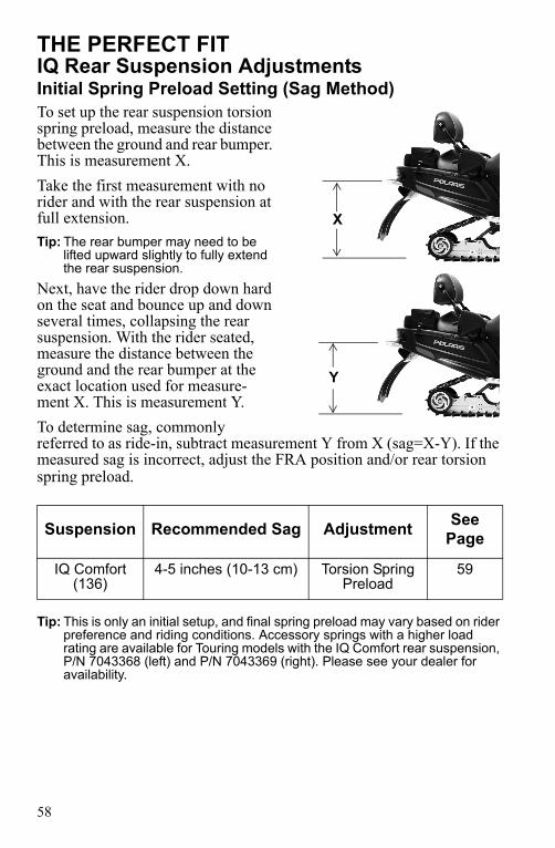
THE PERFECT FITIQ Rear Suspension AdjustmentsInitial Spring Preload Setting (Sag Method)To set up the rear suspension torsion spring preload, measure the distance between the ground and rear bumper. This is measurement X.Take the first measurement with no rider and with the rear suspension at full extension. Tip: The rear bumper may need to be
lifted upward slightly to fully extend the rear suspension.
Next, have the rider drop down hard on the seat and bounce up and down several times, collapsing the rear suspension. With the rider seated, measure the distance between the ground and the rear bumper at the exact location used for measure-ment X. This is measurement Y.To determine sag, commonly referred to as ride-in, subtract measurement Y from X (sag=X-Y). If the measured sag is incorrect, adjust the FRA position and/or rear torsion spring preload.
Tip: This is only an initial setup, and final spring preload may vary based on rider preference and riding conditions. Accessory springs with a higher load rating are available for Touring models with the IQ Comfort rear suspension, P/N 7043368 (left) and P/N 7043369 (right). Please see your dealer for availability.
Suspension Recommended Sag Adjustment See Page
IQ Comfort (136)
4-5 inches (10-13 cm) Torsion Spring Preload
59
X
Y
59
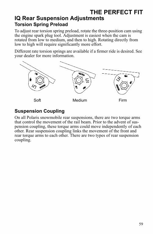
THE PERFECT FITIQ Rear Suspension AdjustmentsTorsion Spring PreloadTo adjust rear torsion spring preload, rotate the three-position cam using the engine spark plug tool. Adjustment is easiest when the cam is rotated from low to medium, and then to high. Rotating directly from low to high will require significantly more effort.Different rate torsion springs are available if a firmer ride is desired. See your dealer for more information.
Suspension CouplingOn all Polaris snowmobile rear suspensions, there are two torque arms that control the movement of the rail beam. Prior to the advent of sus-pension coupling, these torque arms could move independently of each other. Rear suspension coupling links the movement of the front and rear torque arms to each other. There are two types of rear suspension coupling.
Soft Medium Firm

60
THE PERFECT FITIQ Rear Suspension AdjustmentsFront To Rear Coupling and the Front Rear Scissor Stop (FRSS)The front rear scissor stop (FRSS) couples the movement of the front torque arm with the rear torque arm and limits the amount of indepen-dence between the movement of the front torque arm and the rear torque arm.When hitting a bump, the front torque arm starts to compress. The FRSS links that movement to the rear torque arm, causing it to compress and raise the rear suspension up as one, allowing the suspension to hit the bump only once and reducing kickback. The factory setting is usually adequate for all riders and conditions.
Rear To Front Coupling and the Rear Rear Scissor Stop (RRSS)The rear rear scissor stop (RRSS) couples the movement of the rear torque arm with the front torque arm and limits the amount of indepen-dent movement between the rear torque and the front torque arm.Adjusting the RRSS either allows more weight to transfer to the rear for more traction, or allows less weight to transfer to the rear, resulting in improved cornering performance. An adjustment dot is located on the RRSS. This dot is on the longest end of the scissor stop.
Rear Rear Scissor Stop (RRSS) - AttributesMoving the RRSS to a higher position will have the following effects on the suspension:• Reduced weight transfer. • Improved chatter bump ride. • Improved cornering performance.• Increased load carrying capacity (2-up)

61
THE PERFECT FITIQ Rear Suspension AdjustmentsWeight Transfer During AccelerationThe preferred method for controlling weight transfer during acceleration is by adjusting the rear rear scissor stop (RRSS). The factory setting is the best for most trail riding conditions.To decrease weight transfer under acceleration (for improved corner-ing), rotate the RRSS to a higher position.To increase weight transfer or ski lift during acceleration, rotate the RRSS to a lower position. Tip: Your dealer can help you with initial
setup and additional setup instruc-tions to help you achieve your opti-mum ride. A scissor stop tool is also available from your dealer.
HIGH
LOWLOW
MEDIUM

62
THE PERFECT FITHandlebar AdjustmentsUse the RIDER SELECT feature to adjust handlebar position. See page 34. Use the following steps to adjust handlebar angle at the handlebar block.1. Remove the handlebar cover
to expose the handlebar and the four adjuster block bolts.
2. Using a 7/16" wrench, loosen the four nuts on the bottom of the adjuster block (turn han-dlebar to left or right for access to back nuts).
Tip: If necessary, pry the blocks apart with a screwdriver.
3. Adjust the handlebar to the desired height. Be sure han-dlebars, brake lever and throttle lever operate smoothly and do not hit the gas tank, windshield or any other part of the snowmobile when turned fully to the left or right.
4. Torque the front bolts first, then torque the rear bolts. Torque the bolts to 15-17 ft. lbs. (20-23 Nm).
5. Reinstall the handlebar cover.
Handlebar Cover
Adjuster Block Bolts
Nuts

63
THE PERFECT FITAccessoriesPolaris offers a wide range of accessories for your snowmobile to help make each ride more enjoyable.Use only Polaris parts and accessories on your Polaris snowmobile. Use of unapproved parts and accessories may result in:• Non-compliance with government/industry requirements• Voiding of warranty• Injury to self or othersThis applies, but is not limited to the following areas: brakes, clutches, fuel systems, and exhaust systems. Exhaust systems are critical safety areas that must use approved Polaris parts. Please see your Polaris dealer for service.

64
THE PERFECT FITTraction ProductsStudsBefore equipping your snowmobile with traction products, be aware of the laws in your area pertaining to the use of traction products.Use only Polaris traction products on your snowmobile. Track warran-ties are void if track damage or failure results from improper or exces-sive stud installation or the use of non-Polaris traction products.See your dealer about installing studs and/or carbides.NOTICE: Always install wear strips before installing studs. Failure to install wear
strips may result in cooler or tunnel damage. See page 65.Never add shims to the wear strip. Track damage will result because of lack of clearance between upper carrier wheels and track.Use of studs longer than the recommended length on snowmobiles equipped with center coolers will result in center cooler damage or damage to the tunnel.
Track studding will enhance braking control on hard-packed snow or ice, but extreme caution is still required on such surfaces. Steering abil-ity may be reduced on hard-packed snow or ice.When studded tracks are used, increased wear to the brake pads will result from increased braking. Extended-wear brake pad kits are avail-able. See your dealer.NOTICE: Aggressive studding patterns may require grinding protruding stud
bolts flush to prevent idler wheel damage. Maintain track tension on studded tracks on the tight side of the spec to prevent heat exchanger damage. Center of stud must be at least 1 1/8" (2.86 cm) from the outside edge of the track.

65
THE PERFECT FITTraction Productsn Carbide SkagsA skag is a replaceable bar attached to the underside of the ski to assist in turning the snowmobile and to prevent ski wear caused by contact with roads and other bare terrain. Use carbide skags with studded tracks to help maintain proper vehicle steering and control. See page 135.If your snowmobile has carbide skags, it may be necessary to add track studs to maintain proper vehicle control. Maintain a proper balance between the number of studs and the length of carbide on the skags (the more studs you use, the longer the carbide on the skags should be). See your dealer's track studding chart.
Wear StripsTo avoid excessive tunnel wear, tunnel wear strips must be installed whenever track studding is used.Install the appropriate wear strip kit. See your dealer.Wear strips are designed for a specific stud length. See your dealer's studding chart for recommended traction accessories.NOTICE: Whenever wear strips are relocated, be sure there's adequate stud
clearance to the heat exchangers. Lack of clearance may result in damage to heat exchangers.

66
PRE-RIDE INSPECTIONSPre-Ride ChecklistInspect all items on the checklist for proper operation or condition before each use of the snowmobile. Procedures are outlined on the refer-enced pages. Look for a checkmark (n) on the referenced pages to locate the pre-ride inspection items.
Item See PageDrive Belt Condition 125Steering System 68Parking Brake Lock/Brake Lever/Brake System 69, 70, 119Throttle Lever 67Throttle Safety Switch 67Auxiliary Shut-Off Switch (Engine Stop Switch) 73, 87Ignition Switch 73, 87Taillight/Brakelight/Headlight 73Coolant Level 113Gearcase Oil Level 105Engine Oil Level 94Engine Oil Level (check before operating if vehicle was tipped over)
74
Foam Oil Breather Element 102Suspension Mounting Bolts 72Skags (Wear Bars) 65, 135Ski Saddle and Spindle Bolts 72Hood Straps/Latches 68Seat Latches 67Rear Wheel Idler Bolts 72, 131Track Alignment/Condition 71, 132Rail Slide Condition 132

67
PRE-RIDE INSPECTIONSBefore Starting the EngineBefore starting the engine, always refer to all safety warnings pertaining to snowmobile operation. Never start the engine without checking all vehicle components to be sure of proper operation.WARNING! Operating the vehicle with worn, damaged, or malfunctioning components could result in serious injury or death. Never start the engine without checking all vehicle components to be sure of proper operation.
Read and Understand Your Owner's ManualRead the Owner's Manual completely and refer to it often. The manual is your guide to safe and enjoyable snowmobiling experience.
n Throttle LeverThe throttle and brake are the primary controls of your snowmobile. Always make sure both are functioning properly.Squeeze the throttle lever to make sure it compresses evenly and smoothly. When released, the lever should immediately return to the idle position without binding or hesitation. If the throttle does not func-tion smoothly, or if you discover excessive lever freeplay, DO NOT start the engine. Have the throttle serviced immediately.
n Throttle Safety SwitchTest the throttle safety switch system before the snowmobile is operated. See page 84 for procedure.
n Seat LatchesEnsure that the seat latches are securely in place before every use of the snowmobile.

68
PRE-RIDE INSPECTIONSBefore Starting the Enginen Hood LatchesThe hood of the snowmobile protects the operator from moving parts as well as aiding in sound emission control and other functions. Under no circumstances should your snowmobile be operated with the hood open or removed. Always ensure that the hood straps are in good condition and that the latches are securely in place before operating the snowmo-bile.
n Steering SystemWARNING! Ice and snow build-up may interfere with the steering of your snowmobile, resulting in serious injury or death. Keep the underhood area free of snow and ice.Before driving, manually turn the skis to the left and right to be sure ice and snow are not interfering with full left and right steering. If difficulty is encountered, remove ice and snow build-up that may be obstructing the steering linkage.If your snowmobile is equipped with RIDER SELECT, perform this check in both the full up and full down steering positions.

69
PRE-RIDE INSPECTIONSBefore Starting the Enginen BrakesAlways check the following items for proper operation before starting the engine.Brake Lever TravelSqueeze the brake lever. It should move no closer to the handgrip than 1/2" (1.3 cm). A smaller distance indicates low brake fluid level or air in the hydraulic system. Refer to the brake bleeding infor-mation on page 121.Brake Lever FeelIf the brake lever feels “spongy” when squeezed, check the brake fluid level and condition. Add fluid as needed. See page 120.Check for the presence of air in the fluid system. See page 121 for more information, or see your dealer for service.WARNING! Continued use of “spongy” brakes may cause a complete loss of brakes, which could result in serious injury or death. Always have the brakes serviced at the first sign of sponginess.
1/2" (1.3 cm)

70
PRE-RIDE INSPECTIONSBefore Starting the Enginen Parking Brake Lever LockUse the parking brake lever lock only when you want the snowmobile to remain stationary; for example, when parked on an incline for a period of five minutes or less.1. Brake Lever2. Parking Brake Lever Lock3. Master Cylinder Reservoir/Cover4. Fluid Level Indicator
Lock EngagementTo engage the lock, squeeze the brake lever tightly and push forward on the lock. Hold the lock forward while releasing the brake lever.Tip: If the brake lever is squeezed tightly enough, the lock will move freely into
place. Do not force the lock or it may break. The parking brake light on the gauge will light up if the parking brake lever lock is set while the engine is running. It will also be lit when the service brake is in use. If the parking brake light does not come on when the parking brake or service brake is in use, have it serviced by your dealer.Lock ReleaseTo release the lock, squeeze the brake lever tightly. The lock will return to the unlocked position. WARNING! If the parking brake lever lock is partially or entirely engaged while riding, the brakes may overheat, resulting in brake damage. In extreme cases it could cause a fire, which could result in serious injury or death. Always ensure that the lever lock is completely disengaged before operating the snowmobile.
1 2 3 4

71
PRE-RIDE INSPECTIONSBefore Starting the Enginen Track InspectionWARNING! Operating the snowmobile with a damaged track increases the possibility of track failure, which could cause loss of control resulting in serious injury or death. Always inspect the track for damage before using the vehicle.WARNING! Use of traction products such as studs increases the possibility of track damage and/or failure. Driving at high speeds for extended periods of time in marginal lubrication could severely damage track rods, break track edges, and cause other track damage. Examples of marginal lubrication would include frozen bodies of water without snow cover, icy trails, and no-snow conditions.
Track damage or failure caused by operation on ice or poor lubrication conditions voids the track warranty.

72
PRE-RIDE INSPECTIONSBefore Starting the Enginen Suspension InspectionLoose nuts and bolts can reduce your snowmobile's reliability and cause needless repairs and down time. Before beginning any snowmobile trip, a visual inspection will uncover potential problems. Check the follow-ing items on a weekly basis or before any long trip.
Item Check PageSuspension mounting bolts Tightness --Rear idler wheel bolts Tightness 131Rear idler adjusting bolt locknuts Tightness --Torque arm bolts Tightness --Carrier and bogie wheel bolts Tightness --Front torque arm limiter strap Condition --Rail slide Condition 132Track Tension 130All rear suspension components Lubrication 104Ski runner/skag Condition --Ski spindle bolts Tightness --Tie rod end nuts Tightness --

73
PRE-RIDE INSPECTIONSStart the Engine and Checkn Engine Stop SwitchCheck the auxiliary shut-off switch for proper operation. Push the switch down to stop the engine. Pull it up to allow restarting.n Ignition SwitchMake sure the engine stops when the ignition switch is turned to OFF.n LightingCheck the headlight (high and low beam), taillight, and brake light. Replace burned out lamps before operating.n Mirror AdjustmentIf equipped, adjust your mirrors so they can be used to their full advan-tage.n Operating AreaBefore driving away, check your surroundings. Be aware of obstacles and make sure bystanders are a safe distance from the snowmobile.

74
PRE-RIDE INSPECTIONSn Tip-Over InspectionsIn the event of a tip-over or rollover, check the oil level before operating the snowmobile.NOTICE: Failure to check the oil after a tip-over can result in serious engine
damage. Always check the oil level before operating a snowmobile that has tipped over or rolled over.
Inspect the foam oil breather element any time the snowmobile has been tipped onto its left side. Clean the element if oil is present. See page 102.NOTICE: Operating the snowmobile with a clogged foam oil breather element
can result in severe engine damage. Always clean or replace the element as recommended.
In the event of a tip-over or rollover, the engine will stop. To restart the engine, turn the key to the OFF position, then restart.WARNING! Operating a snowmobile with accident damage can result in serious injury or death. Do not operate the snowmobile if vehicle components have been damaged in a collision or tip-over. Have the snowmobile inspected by an authorized Polaris dealer.

75
OPERATIONFuel Safety
Gasoline is highly flammable and explosive under certain conditions.
• Always exercise extreme caution whenever handling gasoline.• Always refuel outdoors or in a well-ventilated area. • Always turn off the engine before refueling.• Do not overfill the tank. Do not fill the tank neck.• Do not smoke or allow open flames or sparks in or near the area where refu-
eling is performed or where gasoline is stored.• If gasoline spills on your skin or clothing, immediately wash it off with soap
and water and change clothing.• Never start the engine or let it run in an enclosed area. Engine exhaust fumes
are poisonous and can cause loss of consciousness or death in a short time.
The engine exhaust from this product contains chemicals known to cause can-cer, birth defects or other reproductive harm. Operate this vehicle only outdoors or in well-ventilated areas.
WARNING
WARNING

76
OPERATIONBreak-In PeriodThe break-in period for your new Polaris snowmobile is the first 500 miles (800 km) of operation. No single action on your part is as impor-tant as following the procedures for a proper break-in. Careful treatment of a new engine and drive components will result in more efficient per-formance and longer life for these components.Polaris recommends the use of Performance Synthetic 4-Stroke oil (PS-4 or PS-4 Plus) for this engine. See page 94.NOTICE: Excessive heat build-up during the first 500 miles (800 km) of
operation will damage close-fitting engine parts. Do not operate at full throttle or high speeds for extended periods during the break-in period.
NOTICE: Use of non-recommended oil may cause serious engine damage. Always use the recommended oil for your Polaris snowmobile.
1. Fill the fuel tank with the recommended fuel. See page 81.2. Check the oil level in the oil tank. See page 94. Add oil if necessary
to maintain at the recommended level.3. Drive slowly at first. Vary the throttle positions. Do not operate at
sustained idle. 4. Perform regular checks on fluid levels, controls and areas outlined
on the daily pre-ride inspection checklist. See page 66.5. During the break-in period, change both the oil and the filter at 500
miles or before seasonal storage, whichever comes first.

77
OPERATIONStarting the Engine1. Turn the key to the ON position.NOTICE: Engaging the starter when the engine is running WILL result in serious
engine damage, especially if the transmission is in reverse. Never engage the starter when the engine is running.
2. Pull the engine stop switch up to the RUN position.3. Do not apply throttle when starting the engine unless extremely cold
temperatures (below -15° F/-26° C) prevent the engine from start-ing.
Tip: Under these conditions, attempt to start the engine without using the throt-tle. If two to three attempts are unsuccessful, apply 1/8 to 1/4 throttle while cranking the engine. Ease off the throttle immediately when the engine starts. Continue to apply just enough throttle to keep the engine running until it idles smoothly.
4. Turn the key to START to crank the engine. Release the key to the ON position when the engine starts.
5. Repeat the cranking procedure as needed until the engine starts.Tip: Always allow the engine to warm up to full operating temperature (150° F/
65° C) before shutting it down. Avoid starting and stopping the engine with less than 5 minutes of run time when the engine is cold.
78
OPERATIONEmergency StartingIf the battery is too weak to start the engine, and a battery charger is not available, the engine can be started using jumper cables and a charged battery from another vehicle. Carefully read and follow the instructions on the following pages.WARNING! Improperly connecting or disconnecting jumper cables can result in an explosion and cause serious injury or death. When connecting jumper cables, always connect the negative (usually black) cable last. When removing jumper cables, always disconnect the negative (usually black) cable first.WARNING! Loose-fitting clothing can get caught in the engine when the vehicle is running with the hood open. This can cause serious injury or death. Remove or control all items that could catch in the engine, including scarves, gloves, jackets and clothing straps and hooks.NOTICE: If a car or truck battery will be used to jump start the snowmobile, turn
the engine off. A running engine will put out too much electrical current for the snowmobile battery. Never attempt to jump start a discharged battery that is frozen.

79
OPERATIONEmergency Starting1. Always wear eye protection when jump starting your vehicle.2. Keep bystanders away from the vehicles.3. Perform the emergency starting procedure in a well-ventilated area.4. Position the vehicles close enough for the jumper cables to reach
easily between the batteries, but do not allow the vehicles to touch each other.
5. Lock the parking brakes on both vehicles to prevent accidental movement.
6. Open the hood and remove the left side panel.7. Decide which of the jumper cables will be positive (usually red or
yellow) and which will be negative (usually black).WARNING! Never connect a jumper cable to the fuel system or fuel lines.8. Pull back the red plastic boot covering the positive terminal of the
weak battery. Connect one end of the positive jumper cable to the positive terminal of the weak battery.
9. Connect the other end of the positive jumper cable to the positive terminal of the charged battery.
NOTICE: Make sure that the end of the negative cable by the weak battery is not contacting the snowmobile battery or chassis.
10. Connect the other negative end of the jumper cable to the negative terminal of the charged battery.
11. Connect the end of the negative jumper cable by the weak battery to the CHASSIS of the snowmobile. There may be a small spark when this is done, but this is normal.
NOTICE: Always be sure that the jumper cables do not interfere with the belts, pulleys or clutches on either vehicle.

80
OPERATIONEmergency Starting12. Make sure that the engine stop switch is in the UP position. 13. Attempt to start the vehicle. 14. If the engine does not turn over (crank over), wait 30 to 60 seconds
and attempt to start the engine again. If the engine does not start, wait another 1 to 2 minutes and attempt to start the engine again.
15. If the engine still does not start, try adjusting the clips on the jumper cable ends to ensure that they have a good electrical connections. Repeat step 14.
16. If the engine still does not start, remove the jumper cables as out-lined in step 17 and transport the snowmobile to an authorized Polaris dealer for service.
17. Carefully remove the jumper cables in this order: A. Remove the negative end of the jumper cable from the
snowmobile chassis.B. Remove the negative end of the jumper cable from the
charged battery.C. Remove the positive end of the jumper cable from the
charged battery.D. Remove the positive end of the jumper cable from the
weak battery.18. Reinstall the left side panel.19. Close and secure the hood.

81
OPERATIONFuelNOTICE: Damage to the fuel pump will occur if the snowmobile is operated with
an empty fuel tank. Do not allow the snowmobile to run out of fuel. Always refuel when the level is low.
For peak performance, Polaris recommends the use of 91 octane or higher fuel. Although 87 octane fuel is usable, some engine perfor-mance will be lost and fuel economy will decrease. Do not use lower than 87 octane fuel. Do not use fuel containing more than 10% ethanol (including E85).NOTICE: Operating with obstructed fuel systems will result in serious engine
damage. Perform maintenance as recommended.NOTICE: Prolonged exposure to petroleum based products may damage paint.
Always protect painted surfaces when handling fuel.
Fuel LevelThe fuel symbol and the last fuel bar on the MFD gauge will blink when the fuel level reaches 1/8th tank. There will be approximately one gallon of fuel remaining. Refuel as soon as possible. Do not allow the snowmo-bile to run out of fuel.
Fuel System DeicersIf you use non-oxygenated fuel, Polaris recommends the regular use of isopropyl-based fuel system deicer. Add one to two ounces per gallon (8-16 ml per liter) of gasoline to prevent engine damage resulting from fuel system icing and lean fuel mixtures. Never use deicers or additives containing methanol. Polaris also recommends the use of Carbon Clean Plus. See page 141 for the part numbers of Polaris products. If you use oxygenated fuel containing ethanol, additional alcohol deic-ers or water absorbing additives should not be used.

82
OPERATIONTrack Warm-Up
A loose track or flying debris could cause serious injury or death. Stand clear of the front of the snowmobile and the moving track. Never hold the snowmobile up or stand behind it while warming up the track. Do not use excessive throttle dur-ing warm-up or when the track is free-hanging. Be sure the rear support is sta-ble.
Use of traction products such as studs, ice growsers, etc. will increase the possi-bility of track damage and/or failure. This could cause loss of control, resulting in serious injury or death. Always inspect for track damage before operating the snowmobile.
WARNING
WARNING

83
OPERATIONTrack Warm-UpFollow these steps to ensure proper warm-up of the engine, drive train and track.1. Use an appropriate stand to securely
support the rear of the snowmobile at the rear bumper. The track should be approximately 4" (10 cm) off the ground.
2. Start the engine and allow it to warm up two to three minutes.
3. Depress the throttle abruptly and allow the track to rotate several revo-lutions.
Tip: It will take longer to warm up the track sufficiently during colder outdoor temperatures.
4. Release the throttle, apply the brakes, shut off the engine and lower the snowmobile to the ground.
5. Grasp the skis by their front loops and move them from side to side to loosen snow and ice.

84
OPERATIONn Engine Stop SwitchPush down on the engine stop switch to ground out the ignition and stop the engine quickly. Pull the switch up to the RUN position to allow restarting.
n Throttle Safety SwitchThe throttle safety switch is designed to limit engine speed to 2400 RPM whenever all pressure is removed from the throttle lever and the throttle cable or throttle valves do not return to the normal closed posi-tion. If the throttle lever is depressed with a throttle valve error, the Mal-function Indicator Lamp will come on and vehicle speed will be limited to 18 MPH (29 km/h).See page 38 for more information about conditions that will cause vehi-cle speed and engine speed to be limited.WARNING! Operating the snowmobile with a faulty throttle safety switch can result in serious injury or death in the event of an accident. If the throttle safety switch does not limit engine speed to 2400 RPM when all pressure is removed from the throttle lever during a throttle malfunction, immediately push down the engine stop switch. Do not start the engine again until the malfunction has been corrected by your dealer.This four-stroke snowmobile has a self-diagnostic check of the throttle safety switch. The switch operation is checked through the engine con-trol unit for correct operation. If a defective switch is detected by the self diagnostics system, the MIL will illuminate. Take your snowmobile to an authorized Polaris dealer for diagnosis and repair if the MIL is illu-minated.
Stop Switch

85
OPERATIONn Throttle LeverWARNING! An improperly functioning throttle lever may cause erratic snowmobile behavior and loss of control, which could result in serious injury or death. If the throttle lever does not work properly, DO NOT start the engine.If the engine speed limits at 2400 RPM when the throttle lever is released:1. Turn the ignition switch to OFF.2. Visually inspect the throttle cable and throttle body to determine
what caused the safety switch to activate.3. Test the throttle lever by compressing and releasing it several times.
The lever and cable must return to the idle position quickly and completely.
4. If the throttle lever operates properly, turn the ignition switch on and go through normal starting procedures.
5. If the engine doesn't start, take the snowmobile to an authorized Polaris dealer for service.
Tip: Excessive freeplay in the throttle cable may cause the safety switch to acti-vate, preventing the engine from starting. If this occurs, return the snowmo-bile to an authorized Polaris dealer for service.
Turbo Noise (Turbo models)Under some conditions, when the throttle lever is released the boost pressure dump valve will release pressure, and you may hear the sound of escaping air. This is a normal occurrence on turbo-charged models.

86
OPERATIONElectronic Reverse (PERC 4t)Electronic reverse will activate only when the vehicle is stopped and engine speed is below 2500 RPM. Maximum vehicle speed when oper-ating in reverse will be approximately 12 MPH (19 km/h).WARNING! Improper reverse operation, even at low speeds, may cause loss of control, resulting in serious injury or death. Damage will occur to the gearcase or transmission if shifting is attempted when the engine is operating above idle speed.• Shift to or from reverse only when the snowmobile is stopped and when
engine speed is at idle.• Look behind the snowmobile before and while backing.• Avoid sharp turns.• Apply throttle slowly.
NOTICE: Engaging the starter when the engine is running WILL result in serious engine damage, especially if the transmission is in reverse. Never engage the starter when the engine is running.
Engaging Reverse1. Stop the snowmobile and
leave the engine idling.2. Make sure the area behind
your snowmobile is clear.3. Push the yellow reverse but-
ton on the left-hand control for one second, then release.
Tip: A reverse light on the instrument panel will indicate that the transmission is in reverse.
4. Apply the throttle slowly to make sure the transmission is in reverse.
Tip: If the engine stops running, the transmission will be in forward gear when it's restarted.
Reverse Button

87
OPERATIONElectronic Reverse (PERC 4t)Disengaging Reverse1. Stop the snowmobile and leave the engine idling.2. Push the yellow reverse button for one second and release. The light
on the instrument panel will shut off.3. Apply the throttle slowly to make sure the transmission is in for-
ward.
n Emergency StoppingThe following chart lists methods for stopping the snowmobile in the event of an emergency. See page 84 for more information about the engine stop switch.
SYSTEM WHAT IT DOES THROTTLECONDITION
Ignition Switch Interrupts ignition circuit AllBrake Slows jackshaft AllEngine Stop Switch Interrupts ignition circuit All

88
OPERATIONDaily StorageAt the end of each ride, park the snowmobile on a level surface and sup-port it at the rear with an appropriate track stand. The track should be suspended approximately 4" (10 cm) off the ground.Remove the key and cover the snowmobile.
TowingDo not use the front bumper to pull or drag the snowmobile. The front bumper is not designed for this type of use and may detach from the vehicle if force is applied.For your safety, do not attempt to use a tow hitch until you've read the following warnings and understand the proper hitch functions.WARNING! Objects towed with a rope have no braking power and can easily collide with the rear of the snowmobile or other objects, resulting in serious injury or death. DO NOT tow toboggans, sleds, saucers, or any type of vehicle with a rope. Only a stiff metal pole connecting the towed object and the tow hitch on the snowmobile should be used. If passengers are to be towed on a toboggan or sled, make sure the pole is at least four feet (1.2 meters) long to prevent any possibility of contact between the snowmobile's track and a person riding in the towed object. Braking distances increase when towing loads. Slow down to maintain control of the snowmobile.
If the snowmobile becomes inoperable and must be towed, and if it isn't possible to use a rigid tow bar, attach the tow rope to the ski spindles (not to the ski loops) to prevent damage to the steering components. Remove the drive belt before towing, and have someone ride on the towed snowmobile to operate the brake and steering when necessary.NOTICE: Towing a disabled snowmobile with the drive belt in place can result in
serious damage to the engine and drive system. Always remove the drive belt from a disabled snowmobile before towing.

89
MAINTENANCEEmission Control InformationAny qualified repair shop or qualified person may maintain, replace, or repair the emission control devices or systems on your snowmobile.Emission Control LabelYour snowmobile is equipped at the time of sale with an emission con-trol information (ECI) label and a factory-installed emissions informa-tion hangtag. These items are required by U.S. Environmental Protection Agency regulations. The ECI label is permanently affixed to either the right side of the tunnel or the engine recoil cover. The ECI label should not be removed, even after you purchase the snowmobile. You may remove the factory-installed emissions information hangtag, which is intended solely for your use in making a purchasing decision.Emission Control Maintenance RequirementsYour snowmobile is certified to operate on gasoline with a minimum octane level of 87 (R+M)/2. If your snowmobile is equipped with a check engine light and it comes on, you must take your snowmobile to a qualified dealer for diagnostic service. Specifications and adjustments for engine tune-ups are located in the Service Manual, which is avail-able to your qualified service technician. Reverse (if equipped) must not be engaged during engine tune-ups.Owner's ResponsibilitiesPlease read the Snowmobile Engine Emissions Limited Warranty, and read the maintenance section of your owner's manual. You are responsi-ble for ensuring that the specified maintenance is performed. Polaris recommends that you contact an authorized Polaris dealer to perform any service that may be necessary.

90
MAINTENANCEPolaris Recommended Maintenance ProgramTo ensure many trouble-free miles of snowmobiling enjoyment, follow recommended regular maintenance and perform service checks as out-lined in this manual. Record maintenance and service in the Mainte-nance Log beginning on page 157.The recommended maintenance schedule on your snowmobile calls for service and maintenance inspections at 150 miles (240 km), 500 miles (800 km) and 1500 miles (2400 km). These inspections should be per-formed by a qualified service technician. For continued optimum perfor-mance and component life, continue maintenance checks at 1500 mile (2400 km) intervals.All necessary replacement parts and labor incurred, with the exception of authorized warranty repairs, become the responsibility of the regis-tered owner. If, during the course of the warranty period, part failures occur as a result of owner neglect in performing recommended regular maintenance, the cost of repairs are the responsibility of the owner. Personal safety is critical when attempting to service or make adjust-ments to your snowmobile. If you're not familiar with safe service or adjustment procedures and the use of tools, or if you don't feel comfort-able performing these tasks yourself, contact an authorized Polaris dealer for service.Polaris does not recommend tipping the snowmobile onto it's side for service. In the event of a tip-over or rollover, check the oil level before operating the snowmobile. Inspect the foam oil breather element any time the snowmobile has been tipped onto its left side. Clean the ele-ment if oil is present. See page 102.NOTICE: Hot components can cause damage to plastic. Always make sure the
exhaust system and engine have cooled if you must tip the snowmobile on its side for service or inspection.

91
MAINTENANCEPeriodic Maintenance Interval TableO = Perform ServiceX = Replace
DA
ILY
orPR
E-R
IDE INITIALLY
Miles (km)
YEA
RLY
or E
VERY
Mile
s (k
m)
Item Pg Instructions(see referenced pages)
150(240)
500(800)
1500(2400)
Engine Stop Switch 73 Test for proper operation. Do not operate if switches fail, see your dealer for service.
OIgnition Switch 73 OThrottle Safety Switch 84 OTaillight 73 Test for proper operation,
replace bulbs as neededO
Brakelight 73 OHeadlight 73 OSkags (Wear Bars) 135 Inspect for wear or damage,
replace when wornO
Fluid Leaks -- Inspect for fluid leaks OParking Brake 70 Test for proper engagement
and release, see your dealer for service
O
Brake Lever 69 Check lever travel and lever “feel”
O
Coolant 113 Inspect level, add as needed OBrake fluid 120 O CHANGE EVERY 2 YEARS
Hood Latches 68 Secure properly, replace if damaged
OSeat Latches 67 ORail Slide 132 Inspect for wear or damage,
replace when wornO
Foam Oil Breather Element
102 Check pre-ride, clean or replace with each oil change. Check/clean after tipping onto left side.
O O O O
Front and Rear Sus-pension and Steering Fasteners
72 Inspect for missing or loose bolts and fasteners, tighten or replace as needed
WEEKLY/BEFORE LONG TRIPS
Front Limiter Strap -- Inspect for wear, damage and missing or loose fasten-ers, replace as needed
WEEKLY/BEFORE LONG TRIPS
Alternator Belt 110 Check tension and condition, replace if worn or damaged
O O O O
Throttle Lever 6785
Verify smooth and proper operation
O O O O

92
MAINTENANCEPeriodic Maintenance Interval TableO = Perform ServiceX = Replace
DA
ILY
orPR
E-R
IDE
INITIALLYMiles (km)
YEA
RLY
or E
VERY
Mile
s (k
m)
Item Pg Instructions(see referenced pages)
150(240)
500(800)
1500(2400)
Track Alignment 132 Verify alignment, adjust as needed
O O O O
Coolant Hoses -- Inspect, replace if worn or damaged
O O O
Heat Exchangers -- Inspect, replace if damaged O O OFuel Lines 109 Inspect, replace if worn or
damagedO O O
Battery 136 Clean terminals, test volt-age
O O O
Track Tension 130 Verify tension, adjust as needed
O O O
Handlebars -- Verify alignment, adjust as needed
O O O
Drive Chain 118 Verify tension, adjust as needed
EVERY
Gearcase Oil 105 Check at 500 mi. (800 km), change every 1000 mi. (1600 km)
O EVERY 1000
(1600)
Rear Suspension 104 Lubricate pivot shafts (more often in wet snow condi-tions)
O O
Bearings 103139
Lubricate drive shaft and jackshaft bearings
O O
Throttle Cable 103 Lubricate O OClutches 124 Verify offset alignment,
inspect for wear, residue, loose bushings, see your dealer for all service
O O
Drive Belt 125 Check tension and condi-tion, replace if worn or dam-aged
O O
Air Filter (Turbo) 110 Inspect for oil and dirt, replace as needed
O O
Oil Change 98102
Replace oil and clean the foam oil breather element
X X
Fuel Filter 109 X X

93
MAINTENANCEPeriodic Maintenance Interval TableO = Perform ServiceX = Replace
DA
ILY
orPR
E-R
IDE
INITIALLYMiles (km)
YEA
RLY
or E
VERY
Mile
s (k
m)
Item Pg Instructions(see referenced pages)
150(240)
500(800)
1500(2400)
Engine Mounts -- Inspect, replace if worn or damaged
O O
Spark Plugs 107 Inspect condition/gap, replace as needed
O O
Exhaust System 111 Check muffler and pipe con-dition, replace damaged or missing components, clean plastic surfaces
O O
Hoses -- Inspect for wear, damage and proper routing, replace as needed
O O
Brake Pads/Disc 119 Inspect, replace if worn or damaged
O O
Fuel Vent Lines 109 Inspect, replace if worn or damaged
O O
Ski Toe 134 Verify alignment, see your dealer for adjustments
O O
Cooling Fins/Shroud -- Inspect and clean O OValve Lash -- See your dealer
FS SpecificationsIntake: 0.08 - 0.15 mmExhaust: 0.15 - 0.20 mmFST SpecificationsIntake: 0.08 - 0.15 mmExhaust: 0.18 - 0.23 mm
1500 (2400)INITIALLY
EVERY10,000 (16,000)THEREAFTER
Cooling System 115 Bleed the cooling system, inspect for leaks and proper circulation
EVERY2000
(3200)
Fuel Filter 109 Inspect, replace as needed EVERY2000
(3200)Rear Suspension Shock Oil
-- See your dealer EVERY2000
(3200)

94
MAINTENANCEEngine OilAlways check and change the engine oil at the intervals outlined in the Periodic Maintenance Table beginning on page 91. Always change the oil filter whenever changing oil. See page 141 for the part numbers of Polaris products.Oil RecommendationsPolaris recommends the use of Performance Synthetic 4-Stroke oil (PS-4 or PS-4 Plus) for this engine. PS-4 has been specially formulated for use in Polaris 4-cycle snowmobile engines. It's a fully synthetic, high performance, multi-viscosity oil designed to provide the ultimate in lubrication performance and protection.Oil may need to be changed more frequently if Polaris PS-4 oil is not used. Follow the manufacturer's recommendations for ambient tempera-ture operation.NOTICE: Mixing brands or using a non-recommended oil may cause serious
engine damage. Always use the recommended oil. Never substitute or mix oil brands.
n Oil Level CheckRead the entire oil check procedure before checking the oil level.The oil level will rise as engine temperature increases. The oil level will be lower when the engine is cold. To obtain a proper oil level reading, the snowmobile must be on a level surface, and the engine coolant tem-perature must be between 145 and 160 degrees F. (63-71 degrees C).Always check the oil level before operating a snowmobile that has tipped over.NOTICE: Severe engine damage may occur if procedures for checking the oil
level are not followed precisely. Always check the oil with the snowmobile positioned on a level surface. Always check the oil level when the coolant temperature is within the specified range.

95
MAINTENANCEEngine Oiln Oil Level CheckThe oil level in the oil bottle may drain below the level of the dipstick if the engine has not run for more than a week. If you're not sure if there is oil in the system, you must first check to make sure oil is in the system before checking the oil level. Perform the “Oil in System Check” proce-dure on page 97 before performing the oil level check.1. Position the vehicle on a level surface.2. If the engine is cold, start the engine and allow it to idle until the
engine coolant temperature reaches the specified range. Proceed to step 4.
3. If the engine has been running, stop the engine and verify that cool-ant temperature is within the specified range for performing the oil check. Allow the engine to cool if necessary. When the coolant is within the specified range, restart the engine and allow it to idle for no more than 20 seconds to circulate the oil back into the tank.
4. Turn the engine off.Tip: Check the oil level within three
minutes, before the coolant tem-perature (and oil level) begin to drop.
5. Remove the dipstick from the oil tank.
6. Clean the dipstick with a clean shop towel and reinstall it, screwing it in completely.
7. Remove the dipstick and view the oil level.
Tip: The oil level reading will be accurate for only one to three minutes after turning off the engine. If the oil check isn't completed within three minutes, reinstall the dipstick. Restart the engine and allow it to idle for no more than 20 seconds to circulate the oil back into the tank.
Dipstick

96
MAINTENANCEEngine Oiln Oil Level Check8. Maintain the oil level in
the safe operating range, between the upper and lower marks on the dip-stick. If the level is low, add the recommended oil in small increments, about 2 ounces (60 ml), and recheck the level.
Tip: If the level is low, or when changing the oil, add only enough oil to bring the level to the bottom of the safe operating range on the dipstick.
9. If the level is high, remove 2 ounces (60 ml) and recheck the level.NOTICE: Do not overfill the oil tank. Engine damage may occur. Always add oil
in small increments and recheck the level to avoid overfilling.10. Recheck the oil level if oil was added or removed, making sure the
coolant temperature is within the specified range. If necessary, con-tinue adding or removing oil until the level is in the safe operating range.
Fill mark for oil changes(at specified coolant temperature)
Safe operating range

97
MAINTENANCEEngine OilOil in System Check1. Position the vehicle on a level surface. Start the engine and allow it
to idle 3-5 seconds (no more than 5 seconds). Turn the engine off. 2. Remove the dipstick. Clean the dipstick with a clean shop towel and
reinstall it, screwing it in completely. Remove the dipstick and ver-ify that oil is present anywhere on the dipstick.
3. If oil is present, continue with the oil level check procedure begin-ning on page 94.
4. If oil is not present, add 1/2 quart (.47 l) of the recommended oil. Reinstall the dipstick, start the engine for no more than 5 seconds, stop the engine, and recheck for the presence of oil.
5. If oil is present, continue with the oil level check procedure begin-ning on page 94.
6. If oil is not present, add another 1/2 quart (.47 l) of oil. Reinstall the dipstick, start the engine for no more than 5 seconds, stop the engine, and recheck for the presence of oil.
7. If no oil is present on the dipstick, check the oil system for leaks and proper operation or see your Polaris dealer.

98
MAINTENANCEEngine OilOil ChangeAlways change the oil at the intervals outlined in the Periodic Mainte-nance Table beginning on page 91. Clean the foam oil breather element with each engine oil change. See page 102.Always use the recommended oil. See page 94, or see your Polaris dealer about oil change kits, which contain a new filter and the recom-mended oil.Tip: A special jumper harness is required for changing the oil on this vehicle.
Please see your Polaris dealer to purchase the harness, which will allow you to use the ignition key to turn over the engine without starting it. You may also need an assistant to help with the oil change.
1. Position the vehicle on a level surface. 2. Make sure the engine coolant temperature is between 145 and 160
degrees F. (63-71 degrees C). If necessary, start the engine and allow it to idle until the coolant temperature is within the specified range.
3. Turn the engine off.CAUTION! Hot oil and a hot exhaust system and engine can cause burns. Do not allow hot oil or hot components to contact skin.4. Open the hood and remove the right side panel.Tip: Clamp orientation is critical to the proper operation of the system. Be aware
of clamp placement and orientation when removing hose clamps. Always reinstall hose clamps in the same location and position.

99
MAINTENANCEEngine OilOil Change5. Remove the oil return hose from the oil tank. Have an assistant
place the end of the hose into a drain pan.6. Disconnect the 2-pin WHITE/RED and GREEN/WHITE starter
motor solenoid control switch harness connector located near the battery.
7. Rotate the plug 90 degrees and reinstall it with the WHITE/RED wire connected.
8. Insert the male pin of the jumper harness into the starter solenoid's female port.
9. Open the handlebar cover. Locate the 3-pin connector with the BROWN and RED/WHITE wires. Plug this connector into the 3-pin connector of the jumper harness.
10. Open the fuse box and remove the 20A EFI fuse from the fuse block.
11. Reinstall the right side panel.12. Have an assistant use the ignition key to turn over the engine. Crank
the engine for 15 seconds.13. Wait 30 seconds to allow the starter motor to cool down.14. Repeat steps 12 and 13 four more times for a total of five cycles.15. Reconnect the oil return line to the oil tank. Make sure the hose and
clamp are properly seated. Make sure the clamp is in the correct ori-entation. Refer to the NOTE following step 4.
16. To prevent oil spillage, wait 3 to 5 minutes to allow any oil in the oil filter cap to drain out before removing it. While waiting, remove the foam oil breather element from the airbox. See page 102.
17. Inspect the foam element. Clean it with soap and water and let it dry. Reinstall it, or install a new element if the existing element is dam-aged or degraded and unable to absorb liquid.

100
MAINTENANCEEngine OilOil Change18. Remove the oil filter cap, then remove the oil filter. Inspect the o-
ring and replace it if it's worn or damaged.19. Install a new filter, then reinstall the cap. Tighten the cap to 18.5 ft.
lbs. (25 Nm).20. Remove the jumper from the starter motor wiring harness. Recon-
nect the solenoid and the originally-installed harness. Reinstall the 20A EFI Fuse.
21. Remove the dipstick from the oil tank. Add 2 quarts (1.9 liters) of the recommended oil. Reinstall the dipstick.
22. Start the engine and allow it to idle for 3-5 minutes. Make sure the engine coolant temperature is between 145 and 160 degrees F. (63-71 degrees C).
23. Stop the engine.24. Remove the dipstick from the oil tank. Clean the dipstick with a
clean shop towel and reinstall it, screwing it in completely.25. Remove the dipstick and view the oil level.
Safe operating range
Fill mark for oil changes(at specified coolant temperature)
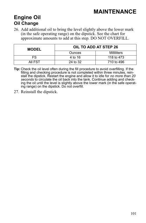
101
MAINTENANCEEngine OilOil Change26. Add additional oil to bring the level slightly above the lower mark
(in the safe operating range) on the dipstick. See the chart for approximate amounts to add at this step. DO NOT OVERFILL.
Tip: Check the oil level often during the fill procedure to avoid overfilling. If the filling and checking procedure is not completed within three minutes, rein-stall the dipstick. Restart the engine and allow it to idle for no more than 20 seconds to circulate the oil back into the tank. Continue adding and check-ing the oil until the level is slightly above the lower mark (in the safe operat-ing range) on the dipstick. Do not overfill.
27. Reinstall the dipstick.
MODEL OIL TO ADD AT STEP 26Ounces Milliliters
FS 4 to 16 118 to 473All FST 24 to 32 710 to 496

102
MAINTENANCEn Foam Oil Breather ElementThe foam oil breather element absorbs small amounts of liquid to pro-tect sensors within the intake system from damage due to oil ingestion. Check the element before each ride. Clean or replace the breather ele-ment at each engine oil change. Inspect the foam oil breather element any time the snowmobile has been tipped onto its left side. Clean the element if oil is present.NOTICE: Operating the snowmobile with a clogged foam oil breather element
can result in severe engine damage. Always clean or replace the element as recommended.
The foam oil breather element is located inside the airbox.1. Open the hood.2. Release the airbox cover retaining
clips and remove the cover.3. Remove the foam breather element.4. Wash the foam element in soapy
water, then rinse thoroughly and let dry.
Tip: If soap and water are not readily avail-able, remove as much liquid as possible by pressing the foam element in paper towels or a similar absorbent material.
5. Reinstall the dry foam element, or install a new foam element.
Tip: Always replace a foam element that is brittle, cracked, crumbling or otherwise damaged. For best performance, rou-tinely replace the foam element with every other engine oil change.
6. Reinstall the airbox cover. Secure all retaining clips.
Element (FS)
Element (All FST)

103
MAINTENANCELubricationDriveshaft BearingInject grease into the fitting on the speedometer sensor housing until grease purges from the seal on the inside of the tunnel. This should take approximately two pumps. Do not use more than four pumps.
Throttle CableLubricate the throttle cable lightly with grease or oil. With the engine off, turn the handlebars to the left and lubricate liberally as shown.
Front SuspensionThe front suspension and steering components do not require lubrica-tion.
Fitting

104
MAINTENANCELubricationRear SuspensionLubricate the suspension pivot shafts with Polaris Premium All Season Grease at the intervals outlined in the Periodic Maintenance Table beginning on page 91 and before seasonal storage. When operating in heavy, wet snow conditions, lubricate every 500 miles (800 km).Lack of lubrication will adversely affect your ride and the life of the sus-pension. For more information about suspension lubrication and adjust-ments, see your Polaris dealer.IQ Comfort Rear Suspension

105
MAINTENANCEGearcase Oiln Gearcase Oil CheckCheck and change the gearcase oil at the intervals outlined in the Periodic Maintenance Table beginning on page 91.Polaris recommends the use of Polaris Synthetic Chaincase Lube. See page 141 for the part numbers of Polaris products.The dipstick is located on the lower front side of the gearcase. Maintain the oil level in the safe operating range, between the upper and lower marks on the dipstick.1. Position the vehicle on a level
surface.2. Remove the dipstick and wipe it
dry with a clean cloth. Reinstall the dipstick.
3. Remove the dipstick and view the oil level.4. Add the recommended oil as needed. Do not overfill.5. Reinstall the dipstick.
Dipstick
SAFE Range

106
MAINTENANCEGearcase OilGearcase Oil ChangeThe drain plug is located on the bottom of the gearcase.Polaris does not recommend tipping the snowmobile onto it's side for service. Any time the snowmobile is tipped onto it's left side, always check the oil level and clean the foam oil breather element. See page 102.1. Position the vehicle on a level sur-
face.2. Remove the drain plug and drain the
oil into a drain pan. Allow the oil to drain completely.
Tip: The sealing surfaces on the drain plug and the gearcase should be clean and free of burrs, nicks or scratches.
3. Reinstall the drain plug. Torque to 6-10 ft. lbs. (8-13 Nm).
4. Remove the dipstick.5. Add 9 oz. (266 ml) of the recommended oil. Do not overfill.6. Reinstall the dipstick, making sure it is seated properly.
Drain Plug

107
MAINTENANCESpark PlugsA new engine can cause temporary spark plug fouling due to the preser-vative added during the assembly process. Avoid prolonged idle speeds, which cause plug fouling and carbonization.NOTICE: Using non-recommended spark plugs can result in serious engine
damage. A spark plug with a heat range too high will always cause engine damage if the engine is operated in conditions more severe than intended for that plug. Always use the spark plugs recommended for your snowmobile.
• Use recommended spark plugs with the proper gap. Refer to your Owner's Manual Supplement for the specific spark plug to be used in your snowmobile.
• Use only resistor-type spark plugs.• Torque spark plugs to 18-20 ft. lbs. (24-27 Nm).Check the spark plug firing end condition after the engine has been warmed up and the vehicle has been driven at higher speeds. If a plug is fouled, replace the plug with a new plug.CAUTION! A hot exhaust system and engine can cause burns. Wear protective gloves when removing a spark plug for inspection.

108
MAINTENANCESpark PlugsNormal Spark PlugThe normal insulator tip is gray, tan or light brown. There will be few combustion deposits. The electrodes are not burned or eroded. This indi-cates the proper type and heat range for the engine and the service.Tip: The tip should not be white. A white insulator tip indicates overheating,
caused by use of an improper spark plug or incorrect throttle body adjust-ments.
Wet Fouled Spark PlugThe wet fouled insulator tip is black. A damp oil film covers the firing end. There may be a carbon layer over the entire nose. Generally, the electrodes are not worn. General causes of fouling are excessive oil or rich fuel mixture.

109
MAINTENANCEIntake FiltersThe intake foam filter limits snow ingestion into the intake system. When operating in loose powder snow, check the top of the foam filter periodically to remove any accumulation of snow.
Fuel InjectorsAll fuel injector service must be performed by an authorized Polaris dealer. Do not attempt to clean or service the fuel injectors.
Fuel PumpAll fuel pump service must be performed by an authorized Polaris dealer. Do not attempt to service the fuel pump.
Fuel FilterSee your Polaris dealer for replacement of the fuel filter at the intervals outlined in the Periodic Maintenance Table beginning on page 91.
Fuel LinesInspect the fuel lines regularly for signs of deterioration or damage. Always check fuel line condition after periods of storage. Normal dete-rioration from weather and fuel compounds may occur. Replace worn or damaged fuel lines promptly.NOTICE: Kinking the fuel lines or using a pliers or similar tools to remove fuel
lines may cause damage to the lines. If a fuel line has been damaged or kinked, replace it promptly.

110
MAINTENANCEn Alternator Belt InspectionInspect the alternator belt condition and tension before each ride.1. Stop the engine.2. Open the hood.3. Inspect the belt for wear,
cracks or other damage. If the belt is worn or damaged, install a new belt.
4. Grasp the alternator belt and attempt to twist it.
5. If the belt rotates 1/4 turn (90 degrees) or more (as shown), tighten the belt or install a new belt.
Air Filter (Turbo)Inspect the air filter for oil and dirt accumulation at the intervals out-lined in the Periodic Maintenance Table beginning on page 91. 1. Open the airbox.2. Remove the air filter. 3. Shake or pat the filter to clean it, or install a new filter. Do not
attempt to clean the filter with liquids.
Foam Oil Breather FilterClean or replace the breather element at each engine oil change. Inspect the foam oil breather element any time the snowmobile has been tipped onto its left side. Clean the element if oil is present. See page 102.

111
MAINTENANCEExhaust SystemCheck the exhaust system for wear or damage at the intervals outlined in the Periodic Maintenance Table beginning on page 91.CAUTION! Hot exhaust system parts can cause burns. Allow adequate time for the exhaust system to cool. Never perform this procedure with the engine running.1. Allow the engine and exhaust system to cool completely.2. Open the hood.3. Inspect the muffler and pipes for cracks or damage. Check for weak
or missing retaining springs or damper/support grommets.4. Replace any damaged or missing components.5. Clean the plastic surfaces next to the muffler with aerosol Carbure-
tor and Throttle Body Cleaner. See page 141 for the part numbers of Polaris products.
6. Close the hood.
112
MAINTENANCECooling SystemCoolantThe coolant supplied in the system is a 60/40 mixture of ethylene-glycol and distilled water. This mixture provides protection against freezing. Contact your dealer if greater protection is required.Use Premium 60/40 anti-freeze coolant, which is already premixed and ready to use. Do not dilute with water. Never exceed a 60% antifreeze/40% water mixture. See page 141 for the part numbers of Polaris prod-ucts.Tip: Never add tap water to the cooling system. Minerals cause deposits and
may react adversely with the metals in the engine and cooling system.Use of a non-standard pressure cap will not allow the recovery system to function properly. If the pressure cap needs replacement, contact your dealer for the correct part.CAUTION! Steam and hot liquids will cause burns to your skin. Never remove the pressure cap when the engine is warm or hot.

113
MAINTENANCECooling Systemn Coolant LevelThe engine coolant level is controlled by the recovery system. The recovery system components are:• Coolant reservoir bottle• Filler neck• Pressure cap• Coolant overflow tank• Connecting hosesAlways maintain the coolant level at the “COLD FILL” mark on the cool-ant overflow tank (when the engine is cold).NOTICE: Operating the snowmobile with insufficient coolant will result in
overheating and serious engine damage. Always maintain the coolant level as recommended.
“COLD FILL” Mark

114
MAINTENANCECooling SystemCoolant High Temperature Indicator LightThe high temperature indicator light will illuminate when engine cool-ant temperature becomes too hot for safe continued operation of the engine. Stop the snowmobile and allow the engine to cool. Place snow on the coolers to help cool the engine. If coolant is low in the coolant reservoir bottle, add coolant to the bottle. Do not open the radiator pres-sure cap.CAUTION! Steam and hot liquids will cause burns to your skin. Never remove the pressure cap when the engine is warm or hot, or if any part of the cooling system is warm or hot.NOTICE: Operating the snowmobile when the high temperature indicator light is
illuminated can result in serious engine damage. Always stop the snowmobile and cool the engine when the high temperature indicator light illuminates.
Drive in adequate snow to prevent overheating. If you must drive your snowmobile after the high temperature indicator light has illuminated, drive in deep snow. Drive slowly and stop frequently to allow the engine to cool down. Engine performance will be reduced if you continue oper-ating when the high temperature light is illuminated.

115
MAINTENANCECooling SystemFlushing the Cooling SystemTo ensure that the coolant maintains its ability to protect the engine, the system should be completely drained every two years and a fresh mix-ture of antifreeze and distilled water should be added. Have your Polaris dealer perform this service.
Bleeding the Cooling SystemBleed the cooling system at the intervals outlined in the Periodic Main-tenance Table beginning on page 91. In addition, bleed the cooling sys-tem any time one or more of the following conditions exist.• A component of the cooling system has been serviced or replaced
(including coolers, radiator, engine, coolant lines and oil cooler)• A cooling system failure occurs, resulting in coolant loss• A coolant line has been disconnected for any reason• A coolant leak occurs
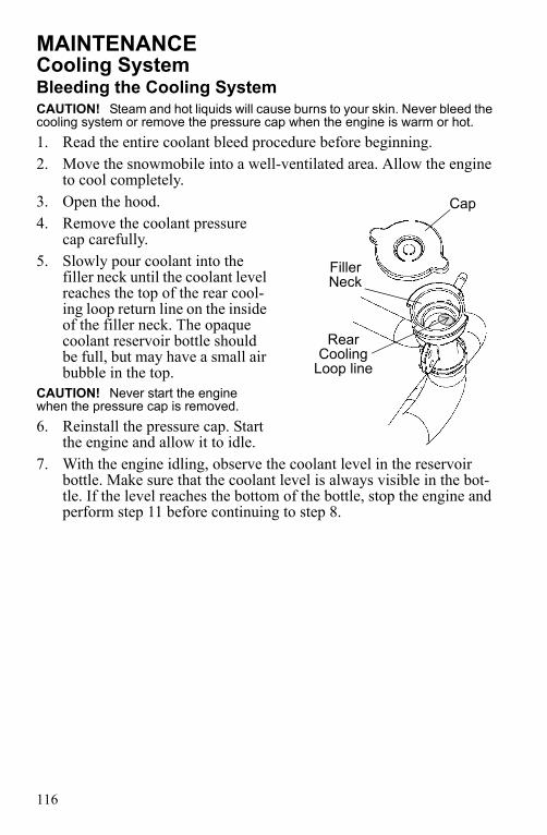
116
MAINTENANCECooling SystemBleeding the Cooling SystemCAUTION! Steam and hot liquids will cause burns to your skin. Never bleed the cooling system or remove the pressure cap when the engine is warm or hot.1. Read the entire coolant bleed procedure before beginning.2. Move the snowmobile into a well-ventilated area. Allow the engine
to cool completely.3. Open the hood.4. Remove the coolant pressure
cap carefully.5. Slowly pour coolant into the
filler neck until the coolant level reaches the top of the rear cool-ing loop return line on the inside of the filler neck. The opaque coolant reservoir bottle should be full, but may have a small air bubble in the top.
CAUTION! Never start the engine when the pressure cap is removed.6. Reinstall the pressure cap. Start
the engine and allow it to idle. 7. With the engine idling, observe the coolant level in the reservoir
bottle. Make sure that the coolant level is always visible in the bot-tle. If the level reaches the bottom of the bottle, stop the engine and perform step 11 before continuing to step 8.
Cap
Filler Neck
Rear Cooling
Loop line

117
MAINTENANCECooling SystemBleeding the Cooling System8. While observing the coolant reservoir bottle and making sure the
coolant level is visible, observe the engine temperature in the digital display. The temperature should rise steadily, indicating that the sys-tem is bleeding properly.
9. If the temperature does not rise at all after approximately one minute, stop the engine and see your dealer for service.
10. While the engine temperature is rising, allow the engine to idle until the temperature reaches approximately 185° F (85° C). Wait for the level in the bottle to go down. When the level stabilizes (or if the level reaches the bottom of the bottle), stop the engine. If the cool-ant level is unchanged, skip to step 13.
11. Allow the engine to cool, then carefully remove the pressure cap and add coolant through the filler neck until the reservoir bottle is full. Reinstall the pressure cap and start the engine.
12. Repeat steps 10-11 until the the coolant level in the bottle no longer falls at an engine temperature of 185° F (85° C) or greater.
13. Feel the coolers at the rear of the snowmobile (rear cooler, de-icers, grippers, as equipped). These components should be warm to the touch, indicating the thermostat is open and the entire cooling sys-tem is bleeding.
14. Some air bubbles may still be trapped in the rear cooler. To ensure they are removed, ride the snowmobile at various throttle openings for 2-3 miles (3-5 km). Recheck the coolant level in the reservoir bottle. The bottle should be full.
15. Feel the coolers on both sides of the snowmobile. If the coolers are warm, coolant is circulating through the system properly.
16. Stop the engine. Allow it to cool completely.17. Remove the coolant overflow tank cap. Add coolant to the “COLD
FILL” mark on the tank. Reinstall the cap.

118
MAINTENANCEDrive Chain TensionCheck drive chain tension weekly and before each long trip. To obtain correct chain tension:1. Rotate the driven clutch
counterclockwise to move all chain slack to the tensioner side. Lock the brake lever lock, or have an assistant hold the brake lever firmly.
2. Loosen the adjuster bolt jam nut.
3. Finger tighten the adjuster bolt until it can no longer be adjusted by hand, then back off 1/4 turn.
4. Tighten the jam nut while holding the adjuster bolt. Torque to 18-23 ft. lbs. (24-31 Nm).
5. Release the brake lever lock.
Adjuster Bolt
Jam Nut

119
MAINTENANCEBrakesn Hydraulic Brake InspectionInspect the brake lever reserve before each use of the snowmobile. See page 69.Brake pads must be replaced when the brake pad material becomes thin-ner than the backing plate, approximately 1/16" (1.5 mm). A kit is avail-able for replacing brake pads. See your dealer.WARNING! Brake failure during operation can result in serious injury or death. Properly functioning brakes are vital to your safety. Be sure the brake pads do not drag on the disc and that brake lever travel is not excessive. Always replace brake pads when the brake pad material becomes thinner than the backing plate, approximately 1/16" (1.5mm).
Brake Components• Brake Disc• Bleed Screw• Brake Line• Brake Caliper• Brake Pad Material -
Replace when thickness is less than 1/16" (1.5 mm).
Excessive Lever TravelHydraulic brakes are self-adjusting, but if excessive brake pad clearance develops bring the snowmobile to an authorized Polaris dealer for inspection and adjustment.
Brake Disc
Bleed Screw
Brake Pad Material
Brake Line
Brake Caliper

120
MAINTENANCEBrakesn Brake Fluid
After opening a bottle of brake fluid, always discard any unused portion. Never store or use a partial bottle. Brake fluid is hygroscopic, meaning it rapidly absorbs moisture from the air. The moisture causes the boiling temperature of the brake fluid to drop, which can lead to early brake fade and the possibility of accident or serious injury.
Keep the master cylinder cover free of dirt and debris. The vent slits allow for diaphragm movement, and if they become plugged, movement of brake fluid below the diaphragm may be restricted, altering brake function.
NOTICE: Brake fluid will damage decals, paint and some plastics. Always wipe up spills immediately.
Replace brake fluid at least every two years with Polaris DOT 4 high tem-perature brake fluid. See page 141 for the part numbers of Polaris products.The brake fluid level can be seen through the fluid level indicator (a plastic sight glass) in the master cyl-inder reservoir. If the fluid is suffi-cient, the sight glass will be black. If the sight glass is any color other than black, add brake fluid.
WARNING
Sight Glass

121
MAINTENANCEBrakesBleeding the Hydraulic Brake SystemAir in the hydraulic brake system will cause spongy brake lever action. Bleed the system before operating the snowmobile.WARNING! Operating the vehicle with a spongy brake lever can result in loss of brakes, which could cause an accident and lead to serious injury or death. Never operate the vehicle with a spongy-feeling brake lever.During the bleeding procedure, keep the brake handle as level as possi-ble. The reservoir must be in this position to minimize the possibility of air entering the system through the reservoir vent.1. Remove brake master cylinder reservoir cover and gasket.2. Fill the master cylinder reservoir to between the MIN and MAX
marks or 1/4"-5/16" (.6-.8 cm) below the lip of the reservoir open-ing. Reinstall the gasket and cover.
3. Slip a rubber tube over the ball of the bleeder valve and direct the flow of fluid into an approved container.
4. Squeeze the brake lever a full stroke. Then unscrew the bleeder valve 3/4 of a turn to release air.
5. Close the bleeder valve and release the brake lever.6. Repeat steps 4 and 5 until fluid flows from the bleeder valve in a
solid stream free of air bubbles.WARNING! Overfilling the master cylinder leaves no room for fluid expansion and may cause the brakes to lock, resulting in serious injury or death. Always add brake fluid to the fill line as recommended.7. After bleeding is complete, refill the reservoir to the proper level.
See page 120. 8. Reinstall the gasket and cover.

122
MAINTENANCELightsRemoving Halogen BulbsTip: Do not touch a halogen bulb with bare fingers. Oil from skin leaves a resi-
due, causing a hot spot that will shorten the life of the lamp. If fingers do touch the bulb, clean it with an alcohol-moistened towel.
1. Remove the plenum cov-ering from the headlight assembly.
2. Lift the rubber boot to expose the bulb.
3. Push down on the spring to release it from the housing.
4. With the wire harness attached to the bulb, withdraw the bulb from the housing.
5. Grasp the bulb by its metal base and carefully separate the bulb from the harness.
Installing Halogen Bulbs1. Hold the bulb by its metal base and install it into the wire harness.2. Insert the bulb into the housing.3. Connect the spring to the housing.4. Carefully flip the spring back into the housing, placing it around the
wire harness.5. Reinstall the plenum covering on the headlight assembly.6. Adjust headlight aim. See page 30.
Replacing Taillight Bulbs1. Remove the screws securing the taillight lens.2. Push the bulb in and twist counterclockwise and replace the bulb.3. Replace the taillight lens.
Spring
Harness
Bulb

123
MAINTENANCEElectrical System
RELAY LABEL FUSE LABEL ITEM POWEREDSTART SOLENOID
RELAYGround side of start solenoid
CHASSISRELAY
SPARE 20A NoneACCESSORYEMERGENCYSPARE 30A
Accessory plugs
CHASSIS30A
High beamsLow beamsHandwarmersThumbwarmerTail lampBrake lampAlternator coils
EFIRELAY
EX. SENSORGAUGE 20A
REVERSE SHIFT
Exhaust sensorGaugeReverse shiftAccessory projector beam relayDiagnostic plug
IGNITION 20A Ignition relay power
EFI20A
Cam phase sensorECU hold-on powerReverse limit switchForward limit switchStart relay coilChassis relay coilIgnition relay coilFuel pump relay coilFan relay coilFuel pump relay powerPTO injectorMAG injectorWastegate
IGNITION RELAY PTO ignition coilMAG ignition coil
FUEL PUMP RELAY Fuel pumpFAN RELAY CAC fan

124
MAINTENANCEClutch SystemPeriodically inspect clutch sheaves for damage, wear or belt residue. To maintain optimum performance, clean with non-oil based cleaners such as isopropyl alcohol.WARNING! If you become aware of higher than normal clutch engagement or an unusual vibration or shift pattern, see your dealer immediately. Do not operate the snowmobile until repairs have been made. WARNING! All clutch maintenance and repairs must be performed by an authorized Polaris dealer. Any unauthorized modifications to clutches, such as adding or removing weights, will void the warranty.NOTICE: The bushings in the weights and rollers of Polaris clutches are made
of a material that may be damaged if lubricated. Do not lubricate clutch bushings.
Clutch Alignment OffsetClutch alignment offset is important for maintaining optimum perfor-mance.Please see your Polaris dealer if you experience a decrease in performance.
Clutch Center DistanceSee your Owner's Manual Supplement for recommended center distance for your snowmobile. If adjustment is necessary, see your dealer.

125
MAINTENANCEClutch Systemn Drive Belt ConditionPeriodically check the condition and tension of the drive belt, and always carry a spare. Inspect the belt for signs of excessive wear: frayed edges, missing cogs, cracks and excessive looseness. Replace the belt if any of these conditions exist. See Drive Belt Troubleshooting on page 147.For improved drive-away during extremely cold temperatures, remove the belt and warm it to room temperature. Reinstall it before starting the snowmobile.
n Drive Belt DeflectionMeasure belt deflection with both clutches at rest and in their full neutral position.Place a straight edge on the belt and apply downward pressure while measuring at point A. This measurement should be 1 1/4" (3.2 cm).
Drive Belt AdjustmentTEAM Clutch1. Loosen the 7/16" jam nut on the belt width adjuster.2. Using a 1/8" Allen wrench, adjust the threaded set screw as needed.Tip: Turn the set screw in (clockwise) to increase the distance between the
sheaves and out (counterclockwise) to decrease the distance.3. Tighten the jam nut.
Straight EdgeMeasure
A

126
MAINTENANCEClutch SystemDrive Belt RemovalNOTICE: Do not attempt to remove the drive belt after operating in reverse. The
snowmobile must be stopped after forward motion to prevent damage to components during belt removal.
1. Stop the engine after operating in a forward motion.Tip: For easier accessibility, make sure the clutch tool access hole is visible
between the 11:00 and 2:00 positions of the clutch sheave.2. Turn the ignition key off.
Wait for the engine to come to a complete stop.
3. Lock the parking brake.4. Open the hood.5. Remove the left side panel.6. Rotate the driven clutch
counterclockwise 1/4 turn by hand to ensure forward engagement before attempt-ing to remove the belt.
7. Install an L-wrench into the open threaded access hole in the outer sheave of the clutch.
8. Turn the wrench clockwise until the sheaves open far enough to remove the belt.
11:00 2:00
Access Hole

127
MAINTENANCEClutch SystemDrive Belt Installation1. Drop the drive belt over the drive
clutch and pull back the slack. Tip: To ensure satisfactory belt life, install
belts so they operate in the same direction of rotation by positioning the identification numbers so that you can read them. If required, separate the sheaves as outlined in the belt removal procedures.
2. Rotate the L-wrench counter-clockwise to tighten the sheaves while working the belt to the outer edge of the sheaves.
3. Remove the wrench.4. Reinstall the side panel.5. Close and secure the hood.

128
MAINTENANCETrack ReplacementWhen replacing the track, always install a track having the lug size rec-ommended for your model. See your Polaris dealer.NOTICE: Installing tracks with larger lugs on snowmobiles equipped with
coolers will result in damage to the cooler or tunnel. Always install a track having the lug size recommended for your model.
Track InspectionWARNING! Broken track rods can cause a rotating track to come off the snowmobile, which could cause serious injury or death. Never operate with a damaged track. Never rotate a damaged track under power.1. Using a hoist, safely lift and sup-
port the rear of the snowmobile off the ground.
2. Rotate the track by hand to check for damage.
3. Carefully examine the track along the entire length of each rod. Bend the track to check for break-age.
4. Replace the track if any rod dam-age is found. Rods

129
MAINTENANCETrack LubricationWARNING! Operating with insufficient lubrication between the rail slide and track guide clips can cause track failure, loss of vehicle control and loss of braking ability, which can result in serious injury or death. Avoid operating for extended periods on ice and other surfaces that have little or no snow for lubrication.
The slide rail requires adequate snow cover for sufficient lubrication. Excessive wear indicates insufficient lubrication. A new rail slide can cause faster heat build-up in limited lubrication, resulting in excessive wear.Track damage or failure caused by operation on ice or under other poor lubrication conditions will void the track warranty.NOTICE: High speed use on hard-packed surfaces is not recommended for
models equipped with a deep lug track. Track lug damage may occur. Keep high speed use to a minimum, including frequent slow-speed intervals for track cooling.

130
MAINTENANCETrack TensionWARNING! Moving parts can cut and crush body parts. When performing the checks and adjustments recommended on the following pages, stay clear of all moving parts. Never perform track measurement or adjustments with the engine running.Track adjustment is critical for proper handling. Always maintain cor-rect tension and alignment.
Tip: Tension adjustments should be made only after the track is warmed up and limber.
1. Turn the engine off.2. Lift the rear of the snowmo-
bile and safely support it off the ground.
3. Place the recommended weight or downward pressure on the track at the specified distance (see chart) ahead of the center of the rear idler wheel.
Tip: Measure at the point where the weight is hanging.
TRACK TENSION DATA CHART
Suspension Slack Measurement Weight Measurement Location
IQ Comfort 7/8"-1 1/8" (2.2-2.9 cm) 10 lbs. (4.54 kg)
16" (40 cm) ahead of rear
idler shaft
10 lbs. (4.54 kg)
16" (40 cm)

131
MAINTENANCETrack Tension4. Check for specified slack between the wear surface of the track clip
and the plastic rail slide.
If the track needs adjustment:5. Loosen the rear idler shaft bolt.6. Loosen the lock nuts.7. Tighten or loosen the track adjusting screws as necessary to provide
equal adjustment on both sides of the track.8. Repeat the measurement on the other side of the track.Tip: Check more frequently when the snowmobile is new.9. Start the engine and slowly rotate the track at least five revolutions.
Let the track come to a stop (do not apply brakes).10. Check track alignment (see page 132) and adjust as necessary.11. Tighten the lock nuts.12. Tighten the idler shaft bolts. Torque to 35 ft. lbs. (47.5 Nm).
Idler Shaft BoltAdjusting
Screw Lock Nut

132
MAINTENANCEn Track AlignmentPeriodically check that the track is centered and running evenly on the slide rails. Misalignment will cause excessive wear to the track and slide rail.1. Safely support the rear of the
snowmobile with the track off the ground.
2. Start the engine and apply a small amount of throttle until the track turns slowly at least five com-plete revolutions. Stop the engine and let the track come to a stop (do not apply brakes).
3. Inspect track alignment by looking through the track window to make sure the rails are evenly spaced on each side. If the track runs to the left, loosen left locknut and tighten the left adjusting bolt. If the track runs to the right, loosen right locknut and tighten the right adjusting bolt.
4. After adjustments are complete, tighten locknuts and torque idler shaft bolts to 35 ft. lbs. (47.5 Nm).
5. Repeat steps 2 and 3 to verify proper alignment.
n Rail Slide WearFor ease of inspection, all Polaris rail slides have a wear limit indicator groove to indicate the minimum per-missible slide thickness. Replace the rail slides if they are worn to the top of the groove at any point along their length. NOTICE: Failure to replace
worn rail slides may result in permanent damage to the track or rails.
Rails
Replace when worn to top of
groove
Minimum Thickness

133
MAINTENANCESteering SystemSteering Inspection and AdjustmentCheck all steering system fasteners weekly and before a long ride. Tighten any loose fasteners.

134
MAINTENANCESteering SystemSki AlignmentWARNING! Improper ski alignment or adjustment may cause loss of steering control, resulting in serious injury or death. Do not attempt to change the ski alignment or camber adjustment. See your Polaris dealer.With the handlebars in a straight ahead position, and with vehicle weight compressing the suspension, measure from the straight edge of the skis at the center of the ski mounting bolt. The measurement between the skis at point X should be 1/8" to 1/4" (3-6 mm) greater than the measurement at point Y. Tip: If the skis are misaligned, we recommend that your dealer correct the align-
ment, since camber adjustment may also be affected.
X
Y
10 in. (25.4 cm)
10 in. (25.4 cm)

135
MAINTENANCESteering Systemn Ski SkagsWARNING! Worn skis and/or skags will adversely affect handling. Loss of vehicle control may result, causing serious injury or death. See your dealer's studding chart for recommended skags. If you install longer or more aggressive carbide skags than the original equipment, it may also be necessary to add track studs to maintain proper vehicle control while turning on hard-packed snow or ice.
Check skags before each use of the snowmobile to ensure positive steer-ing characteristics. Skags must be replaced when worn to half their orig-inal diameter. Tip: Carbide skags must be replaced if any abnormal wear or chipping is found.
Skag ReplacementSome models are equipped with single skags. Some models are equipped with dual skags.1. Raise and support the front of
the snowmobile so the skis are approximately 6" (15 cm) from the ground.
2. Remove the attaching nuts and pry the skag downward.
3. Remove the front end of the skag.
4. Remove the rear end of the skag.
5. Reverse the steps to install a skag.
Skag

136
MAINTENANCEBatteryWARNING! Improperly connecting or disconnecting battery cables can result in an explosion and cause serious injury or death. When removing the battery, always disconnect the negative (black) cable first. When reinstalling the battery, always connect the negative (black) cable last.
Battery Removal1. Remove the left side panel.2. Disconnect the battery hold-down strap.3. Disconnect the black (negative) battery cable first.4. Disconnect the red (positive) battery cable last.5. Lift the battery out of the vehicle.
Battery InstallationWhen installing a new battery, make sure it's fully charged prior to its initial use. Using a new battery that has not been fully charged can dam-age the battery and result in a shorter life. It can also hinder vehicle per-formance. Follow the battery charging instructions on page 138 before installing the battery.1. Ensure that the battery is fully charged.2. Set the battery in the battery holder.3. Connect and tighten the red (positive) cable first.4. Connect and tighten the black (negative) cable last.5. Attach the hold-down strap.6. Verify that cables are properly routed.7. Reinstall the left side panel.

137
MAINTENANCEBatteryBattery StorageWhenever the vehicle is not used for a period of three months or more, remove the battery from the vehicle, ensure that it's fully charged, and store it out of the sun in a cool, dry place. Check battery voltage each month during storage and recharge as needed to maintain a full charge.Tip: Battery charge can be maintained by using a Polaris Battery Tendert
charger (PN 2871076) or by charging about once a month to make up for normal self-discharge. Battery Tendert can be left connected during the storage period, and will automatically charge the battery if the voltage drops below a pre-determined point.
Battery ChargingThe following battery charging instructions apply only to the installa-tion of a sealed battery. Read all instructions before proceeding with the installation of this battery.The sealed battery is already filled with electrolyte and has been sealed and fully charged at the factory. Do not ever pry the sealing strip off or add any other fluid to this battery. The single most important thing about maintaining a sealed battery is to keep it fully charged. Since the battery is sealed and the sealing strip cannot be removed, you must use a voltmeter or multimeter to measure DC voltage.

138
MAINTENANCEBatteryBattery ChargingFor a refresh charge, follow all instructions carefully.1. Check the battery voltage with a voltmeter or multimeter. A fully
charged battery will register 12.8 V or higher.2. If the voltage is less than 12.8 volts, recharge the battery at 1.2 amps
or less until the battery voltage is 12.8 or greater. Tip: When using an automatic charger, refer to the charger manufacturer's
instructions for recharging. When using a constant current charger, use the following guidelines for recharging.
WARNING! An overheated battery may explode, causing severe injury or death. Always watch charging times carefully. Stop charging if the battery becomes very warm to the touch. Allow it to cool before resuming charging.
Tip: Always verify battery condition before and 1-2 hours after the end of charg-ing.
State of Charge Voltage Action
Charge Time(Using constant current
charger @ standard ampsspecified on top of battery)
100% 12.8-13.0 volts None, check at 3 mos. from date of
manufacture
None required
75%-100% 12.5-12.8 volts May need slight charge, if no charge given,
check in 3 months
3-6 hours
50%-75% 12.0-12.5 volts Needs charge 5-11 hours25%-50% 11.5-12.0 volts Needs charge At least 13 hours,
verify state of charge0%-25% 11.5 volts or less Needs charge with
desulfating chargerAt least 20 hours

139
MAINTENANCEExtended StorageOff-season or extended storage of your snowmobile requires preventive measures to aid against deterioration and to prolong the useful life of many components. See page 141 for the part numbers of Polaris prod-ucts.
Cleaning and PreservationProper storage starts with cleaning, washing, and waxing the hood, chassis, and plastic parts. Wipe down remaining surfaces with a damp cloth. Clean and touch up with paint any rusted or previously painted surfaces. Be sure that corrosive salt and acids are removed from surfaces before beginning preservation with waxes and rust inhibitors (grease, oil or paint).The snowmobile should be stored in a dry garage or shed, out of direct sunlight, and covered with a fabric snowmobile cover. Plastic tarp may cause condensation to form and damage snowmobile components.
Battery Maintenance Remove the battery and recharge it as outlined on page 138. Store the battery in a cool, dry place.
Controls and LinkageLubricate all bushings and cables at the intervals outlined in the Periodic Maintenance Table beginning on page 91.
BearingsGrease the jackshaft and drive shaft clutch side bearings with Polaris Premium All-Season Grease or a similar high quality grease to prevent corrosion.
Clutch and Drive SystemRemove the drive belt and store in a cool dry location. Do not lubricate clutch components, except the driven clutch shaft bushing as outlined in the service manual. See your dealer.

140
MAINTENANCEExtended StorageEngine ProtectionFogging the engine is not recommended for this model.NOTICE: Fogging the engine improperly can result in damage to the sensors.
Fogging is not recommended.
Electrical ConnectionsReplace worn or frayed electrical wire and connectors. Be sure wiring harness is properly secured away from sharp edges, steering linkage, moving parts, and hot exhaust parts.
Track and SuspensionModerate track tension should be maintained during summer storage. The snowmobile should be supported off the ground to allow the track to hang freely. See illustration.
Transporting the SnowmobileWhenever the snowmobile is transported:1. Be sure the fuel cap and oil cap are
installed correctly.2. Always tie the snowmobile to the transporting unit securely using
suitable straps.3. Remove the ignition key to prevent loss.

141
POLARIS PRODUCTSPart No. Description
Engine Lubricants2874865 Performance Synthetic 4-Stroke (PS-4) Oil (qt.)
2874866 Performance Synthetic 4-Stroke (PS-4) Oil (gal.)
2876244 Performance Synthetic 4-Stroke (PS-4 Plus) Oil (qt.)
2876245 Performance Synthetic 4-Stroke (PS-4 Plus) Oil (gal.)
2870791 Fogging Oil (12 oz. Aerosol)
2871098 Premium 2-Cycle Engine Oil (qt.)
2871097 Premium 2-Cycle Engine Oil (gal.)
2871240 Premium 2-Cycle Engine Oil (2.5 gal.)
2874438 VES II Synthetic 2-Cycle Engine Oil (qt.)
2874439 VES II Synthetic 2-Cycle Engine Oil (gal.)
2874443 VES II Synthetic 2-Cycle Engine Oil (2.5 gal.)
Chaincase Lubricants2873105 Synthetic Chaincase Lubricant (qt.)
2872951 Synthetic Chaincase Lubricant (12 oz.)
Grease / Specialized Lubricants2871312 Grease Gun Kit, Premium All Season (3 oz.)
2871322 Premium All Season Grease (3 oz. cartridge)
2871423 Premium All Season Grease (14 oz. cartridge)
2871329 Dielectric Grease (Nyogel™)
Coolant2871323 Anitfreeze, 60/40 Premix (gal.)
2871534 Anitfreeze, 60/40 Premix (qt.)
Additives / Miscellaneous2871326 Carbon Clean Plus (12 oz.)
2870652 Fuel Stabilizer (16 oz.)
2872189 DOT4 Brake Fluid (12 oz.)
2872893 Engine Degreaser (12 oz.)
2870505 Isopropyl
2872889 Brake and Clutch Cleaner
2872890 Carburetor and Throttle Body Cleaner

142
TROUBLESHOOTINGEngine and Drive Train TroubleshootingEngine Speed, RPM or Boost is Limited
Engine Doesn't Turn Over
Probable Cause Solution
Engine Management System RPM Reduction Mode is activated
See causes on page 38.
Jammed clutch Check for twisted belt or broken spring. See your dealer.
Jammed track Remove any foreign objects. Slider may be melted to the track clips due to lack of lubrication. Track may be iced up or fro-zen to the ground.
Jammed or broken chaincase sprocket or chain
See your dealer.
Mechanical failure See your dealer.
Probable Cause Solution
Low battery voltage Recharge the battery to 12.8 VDC.
Loose battery connections Check all connections and tighten.
Loose solenoid connections Check all connections and tighten.
Engine stop switch is off Lift the stop switch to the ON position.
Fusible link malfunction See your dealer.
Fuse panel malfunction Check condition of fuses. Replace blown fuses, then see your dealer.
Main relay panel malfunction See your dealer.
Mechanical failure See your dealer.

143
TROUBLESHOOTINGEngine and Drive Train TroubleshootingEngine Turns Over, Fails to Start
Engine Backfires
Probable Cause Solution
Out of fuel Refuel.
Water is present in fuel See your dealer.
Old or non-recommended fuel Replace with fresh recommended fuel.
Fouled or defective spark plugs Inspect plugs and replace if necessary.
No spark to spark plug See your dealer.
Water or fuel in crankcase See your dealer.
Clogged fuel filter Replace the filter.
Low battery voltage Recharge the battery to 12.8 VDC.
Poor engine compression See your dealer.
Mechanical failure See your dealer.
Probable Cause Solution
Weak spark from spark plug Inspect, clean and/or replace spark plugs.
Incorrect spark plug gap or heat range Set gap to specs or replace plugs.
Old or non-recommended fuel Replace with fresh recommended fuel.
Mechanical failure See your dealer.
Loose ignition connections Check all connections and tighten.
Water present in fuel Replace with fresh recommended fuel.
Exhaust manifold leak Inspect and repair, or see your dealer.

144
TROUBLESHOOTINGEngine and Drive Train TroubleshootingEngine Runs Irregularly, Stops or Loses Power
Probable Cause Solution
Engine Management System RPM Reduction Mode is activated
See causes on page 38.
Low battery voltage Recharge the battery to 12.8 VDC.
Water is present in fuel See your dealer.
Poor quality or low octane fuel Replace with fresh recommended fuel.
Loose ignition connections Check all connections and tighten.
Incorrect spark plug gap or heat range Set gap to specs or replace plug.
Fouled or defective spark plug Inspect, clean and/or replace spark plug.
Kinked or plugged fuel vent line Inspect and replace.
Clogged air filter Inspect and clean or replace.
Air flow through intake is too warm (Turbo models)
Boost is limited until cooler air flows through the intake.
Engine management system failure See your dealer.
Engine overheating Stop and cool the engine. See the “Engine Overheating” troubleshooting section on page 145.
Fuel in crankcase See your dealer.
Drive clutch binding See your dealer.
Incorrect clutching See your dealer.
Driven clutch malfunction See your dealer.
Worn drive belt Replace with the recommended belt.
Excessive belt/sheave clearance See your dealer.
Loose torque stop Inspect and adjust.
Other mechanical failure See your dealer.

145
TROUBLESHOOTINGEngine and Drive Train TroubleshootingEngine Overheating
Harsh Drive Clutch Engagement
Drive Belt Turns Over
Drive System Noise
Probable Cause Solution
Inadequate snow conditions Stop and cool the engine. Drive into snow frequently to prevent overheating. See page 21.
Low coolant Stop and cool the engine. Check the cool-ant level. See page 113. Check for leaks. Bleed the system if the coolant level is extremely low.
Restricted air flow to radiator Stop and cool the engine. Clean snow and debris from the radiator.
Probable Cause Solution
Worn drive belt Replace with the recommended belt.
Excessive belt/sheave clearance See your dealer.
Probable Cause Solution
Incorrect belt Replace with the recommended belt.
Incorrect clutch alignment See your dealer.
Broken or loose engine mount See your dealer.
Probable Cause Solution
Broken drive clutch components See your dealer.
Bearing failure (chaincase, jackshaft or front drive shaft)
See your dealer.
Flat spots on drive belt surface Inspect and replace as needed.
Loose drive chain Inspect and adjust (or replace).
Worn drive chain/broken sprocket teeth See your dealer.

146
TROUBLESHOOTINGIQ Comfort Suspension TroubleshootingProblem Solution
Rear suspension bot-toms too easily
• Adjust torsion spring preload to achieve proper static sag (see page 58).
• Change torsion spring to stiffer optional spring (see your dealer).
• Rotate RRSS to higher position (see page 61).
Rides too stiff in rear • Check for binding suspension shafts and grease all pivot points.
• Adjust torsion spring preload to achieve proper static sag (see page 58).
• Change torsion spring to softer optional spring (see your dealer).
• Check track tension (see page 130).• Rotate RRSS to lower position (see page 61).
Snowmobile darts from side to side
• Check ski alignment (see page 134).• Make sure spindles and all steering components turn freely.• Check for excessive play in steering assembly (see your
dealer).• Ensure skags are straight on skis.• Set static sag (see page 58).• Check rail slide/replace if worn (see page 132).• Install Accu-Trak dual skags (see your dealer).
Front end pushes • Check for worn skags.• Check for binding front suspension shafts and steering
components, grease all pivot points (elevate front of machine).
• Set static sag (see page 58).• Install single skag (see your dealer).• Increase IFS preload (if equipped) (see page 55).• Rotate RRSS to higher position (see page 61).
Steering is heavy • Make sure spindles and all steering components turn freely.• Check ski alignment (see page 134).• Check skags and skis for damage.• Set static sag (see page 58).

147
TROUBLESHOOTINGDrive Belt Wear/Burn
Cause Solution
Driving at low RPM
Drive at higher RPM. Gear the machine down. Check belt deflection.
Insufficient warm-up
Warm the engine at least five minutes. Take the drive belt off the snowmobile in extremely cold weather and warm it up. Break snowmobile loose from the snow.
Towing at low RPM
Do not tow in deep snow. Use fast, aggressive throttle to engage clutch.
Riding with high RPM and slow speed (8000 RPM/10 MPH)
Lower the gear ratio. Reduce RPM. Avoid riding in high ambi-ent temperatures. Check for snow ingestion.
Ice and snow build-up between track and tunnel
Warm the engine at least five minutes. Take the drive belt off the snowmobile in extremely cold weather and warm it up. Break snowmobile loose from the snow.
Poor engine perfor-mance
Check for fouled plugs or water, ice, or dirt in the gas tank or fuel line.
Loading snowmo-biles onto trailers
Skis may gouge into trailers and prevent the drivetrain from spinning properly. Use enough speed to drive the snowmobile completely onto the trailer. Push and pull it to finish loading if necessary.
Clutch malfunction Inspect clutch components. See your dealer.
Slow, easy clutch engagement
Use fast, aggressive throttle to engage clutch.
Wrong or missing belt
Always use the recommended belt.
Improper break-in Always break in a new belt and/or clutch by avoiding aggres-sive or high speed operation during the break-in period.

148
WARRANTYService And Warranty InformationObtaining Service and Warranty AssistanceRead and understand the service data and the Polaris warranty informa-tion contained in this manual. Contact your Polaris dealer for replace-ment parts, service or warranty. Your dealer receives frequent updates on changes, modifications and tips on snowmobile maintenance, which may supersede information contained in this manual. Your dealer is also familiar with Polaris policies and procedures and will be happy to assist you.When contacting us about parts, service, or warranty, always provide the following information:1. Serial number2. Model number3. Dealer name4. Date of purchase5. Details of trouble experienced6. Length of time and conditions of operation7. Previous correspondenceUse the page provided near the front of your Owner’s Manual to record the identification numbers of your snowmobile and its engine.Polaris Customer ServiceUnited States: 1-888-704-5290Canada: 1-204-925-7100
149
WARRANTYService And Warranty InformationPolaris Anti-Theft SystemThe Polaris anti-theft system (PATS) monitoring program is designed to aid owners of registered snowmobiles in recovery of stolen machines.Administration1. Polaris snowmobile owner reports theft.
A. In addition to notifying the proper law enforcement officials, the owner must call Polaris Customer Service.B. Owners must provide their name, address, telephone number and the model and serial number of stolen machines.
2. Polaris warranty will provide all dealerships with a monthly updated list of all stolen units to further monitor thefts.
3. Polaris warranty will aid in notifying the proper owner when a unit is recovered

150
WARRANTYLimited WarrantyPolaris Sales Inc., 2100 Highway 55, Medina, MN 55340, provides a ONE YEAR LIM-ITED WARRANTY on all components of the Polaris snowmobile against defects in material or workmanship. This warranty covers the parts and labor charges for repair or replacement of defective parts that are covered by this warranty. The warranty begins on the date of purchase. This warranty is transferable to another consumer, during the war-ranty period, through a Polaris dealer.
RegistrationAt the time of sale, the Warranty Registration Form must be completed by your dealer and submitted to Polaris within ten days. Upon receipt of this registration, Polaris will record the registration for warranty. No verification of registration will be sent to the purchaser as the copy of the Warranty Registration Form will be the warranty entitle-ment. If you have not signed the original registration and received the customer copy, please contact your dealer immediately. NO WARRANTY COVERAGE WILL BE ALLOWED UNLESS THE SNOWMOBILE IS REGISTERED WITH POLARIS.Initial dealer preparation and set-up of your snowmobile is very important in ensuring trouble-free operation. Purchasing a snowmobile in the crate or without proper dealer set-up will void your warranty coverage.
Warranty Coverage and ExclusionsLimitations of warranties and remediesThis warranty excludes any failures not caused by a defect in material or workmanship. The warranty does not cover accidental damage, normal wear and tear, abuse or improper handling. The warranty also does not cover any snowmobile that has been structurally altered, neglected, improperly maintained, used for racing or used for pur-poses other than for which it was manufactured. The warranty does not cover any dam-ages that occur during trailer transit or as a result of unauthorized service or parts. In addition, this warranty does not cover physical damage to paint or finish, stress cracks, tearing or puncturing of upholstery material, corrosion or defects in parts, components or the snowmobile due to fire, explosions or any other cause beyond Polaris’ control.This warranty does not cover the use of unauthorized lubricants, chemicals, or fuels that are not compatible with the snowmobile.The exclusive remedy for breach of this warranty shall be, at Polaris’ exclusive option, repair or replacement of any defective materials, or components or products. THE REM-EDIES SET FORTH IN THIS WARRANTY ARE THE ONLY REMEDIES AVAIL-ABLE TO ANY PERSON FOR BREACH OF THIS WARRANTY. POLARIS SHALL HAVE NO LIABILITY TO ANY PERSON FOR INCIDENTAL, CONSEQUENTIAL OR SPECIAL DAMAGES OF ANY DESCRIPTION, WHETHER ARISING OUT OF EXPRESS OR IMPLIED WARRANTY OR ANY OTHER CONTRACT, NEGLI-GENCE, OR OTHER TORT OR OTHERWISE. Some states do not permit the exclu-sion or limitation of incidental or consequential damages or implied warranties, so the above limitations or exclusions may not apply to you if inconsistent with controlling state law.

151
WARRANTYLimitations of warranties and remediesALL IMPLIED WARRANTIES (INCLUDING BUT NOT LIMITED TO THE IMPLIED WARRANTIES OF MERCHANTABILITY AND FITNESS FOR A PAR-TICULAR PURPOSE) ARE LIMITED IN DURATION TO THE ABOVE ONE YEAR WARRANTY PERIOD. POLARIS FURTHER DISCLAIMS ALL EXPRESS WAR-RANTIES NOT STATED IN THIS WARRANTY. Some states do not allow limitations on how long an implied warranty lasts, so the above limitation may not apply to you if inconsistent with controlling state law.How to Obtain Warranty ServiceIf your snowmobile requires warranty service, you must take it to a Polaris dealer autho-rized to repair Polaris snowmobiles. When requesting warranty service you must present your copy of the Warranty Registration form to the dealer. (The cost of transportation to and from the dealer is YOUR responsibility). Polaris recommends that you use your original selling dealer; however, you may use any Polaris Servicing Dealer to perform warranty service.Please work with your dealer to resolve any warranty issues. Your dealer will contact the appropriate personnel at Polaris if additional assistance is needed.This warranty gives you specific legal rights, and you may also have other rights which vary from state to state.If any of the above terms are void because of state or federal law, all other warranty terms will remain in effect.Engine Oil1. Mixing oil brands or using non-recommended oil may cause engine damage. We rec-ommend the use of Polaris engine oil.2. Damage resulting from the use of non-recommended lubricants may not be covered by warranty.

152
WARRANTYConditions and ExclusionsIn order to qualify for warranty, the product must have been properly set up and tested by a Polaris Dealer (if applicable). Failure of any dealer to perform the required vehicle Pre-Delivery Inspection, perform all applicable service bulletins and have the consumer sign the PDI form prior to delivery may void the warranty. Failure to provide proof of required periodic maintenance upon request may result in denial of warranty coverage. Use of the recommended Polaris products for lubrication and maintenance as directed by the Owner’s manual is highly recommended. Should a failure occur during the warranty period resulting from the use of non-recommended products, warranty coverage may be denied.Warranty does not apply to parts exposed to friction surfaces, stresses, environmental conditions and/or contamination. The following items are excluded from warranty con-sideration if the failure was due to wear or not the direct result of a defect:
Warranty applies to the product only and does not allow for coverage of personal loss. Some items are considered “consumable,” meaning they are considered part of normal maintenance or part of completing an effective repair. The following items are excluded from warranty coverage in the event of a warranty claim:
This warranty also excludes failures resulting from improper lubrication; improper engine timing; improper fuel; surface imperfections caused by external stress, heat, cold or contamination; operator error or abuse; improper component alignment, tension, adjustment or altitude compensation; failure due to snow, water, dirt or other foreign substance ingestion/contamination; improper maintenance; modified components; use of aftermarket components resulting in failure; unauthorized repairs; repairs made after the warranty period expires or by an unauthorized repair center; use of the product in competition or for commercial purposes. Warranty will not apply to any product which has been damaged by abuse, accident, fire or any other casualty not determined a defect of materials or workmanship.
Skis Ski wear rodsTracks Slide railsSuspension components Finished and unfinished surfacesBrake components Carburetor/Throttle body componentsSeat components Engine componentsClutches and components Drive beltsSteering components Hydraulic componentsBatteries Circuit breakers/FusesLight bulbs/Sealed beam lamps Electronic componentsIdler wheels
Spark Plugs Lubricants such as oil, grease, etc.Filters Batteries (unless defective)Fuel Cosmetic damage/repairSealants CoolantsHotel fees MealsTowing charges Shipping/ handling feesMileage Product pick-up/deliveryRentals/Loss of product use Loss of vacation/personal time

153
WARRANTYPolaris Second Year Engine Service ContractSecond Year Engine Service Contract is standard on all eligible new and unused snow-mobiles that were Snow Checked through an authorized Polaris dealer during the March/April Snow Check promotion. The free Second Year Engine Service Contract is honored by all authorized Polaris snowmobile dealers in North America and is transfer-able 120 days after the original purchase date, free of charge, through any Polaris snow-mobile dealer. Coverage on Snow Check units is automatic. Although you do not receive a warranty card, your dealership should have printed a copy of the warranty reg-istration form. This form is your proof of warranty.
Consumer Exclusions• Each repair visit after the first twelve months of standard warranty coverage is subject
to a $50 deductible.• The free Second Year Engine Service Contract applies to the first 5,000 miles or two
(2) calendar years from date of purchase, whichever comes first. Tampering with the odometer shall void all warranties/service contracts. No extensions to coverage under this engine service contract can be given. Used snowmobiles are not eligible under this program.
• Snowmobiles used for commercial purposes or for racing are excluded from coverage.
CoverageCoverage for second year engine failures due to defects in materials and workmanship will be determined by Polaris in its sole discretion. Coverage is automatic with no addi-tional paperwork required. The free Second Year Engine Service Contract is subject to a $50 deductible per visit. Regular, documented service maintenance visits are required to validate this warranty.A partial list of items excluded from coverage includes:• Damage due to accident, fire, explosion, theft, or other causes beyond Polaris’ control.• Damage caused by the failure of other components of the snowmobile.• Failures caused by improper fuel or oil.• Piston seizures, unless caused by a defective engine component.• Failures caused due to improper adjustments.• Failure due to unauthorized service.• Failures due to lack of service as required in the owner’s manual or Polaris updates.
This includes off-season storage as listed in the owner’s manual.• Failure due to use of unauthorized parts or modifications.• Normal wear parts, including but not limited to spark plugs, hoses, batteries, controls,
and recoil ropes are excluded from coverage. Gaskets are covered, as are intake and exhaust manifolds excluding paint coverage.
• Electrical coverage is limited to the ECU box, coils, stator plate, and sensors. Wiring and other electrical components are excluded from coverage.
• Cooling system coverage is limited to the water pump assembly and components, fan, fan bearings, temperature sensor, gasket and seals.
• Non wear related throttle body parts are covered. The fuel pump is covered.• Clutches and related clutch parts, including but not limited to, the drive belt, are
excluded from coverage.• Electrical components are excluded from coverage.• Gearcases and transmissions are excluded from coverage.

154
WARRANTYExported VehiclesEXCEPT WHERE SPECIFICALLY REQUIRED BY LAW, THERE IS NO WAR-RANTY OR SERVICE BULLETIN COVERAGE ON THIS VEHICLE IF IT IS SOLD OUTSIDE THE COUNTRY OF THE SELLING DEALER’S AUTHORIZED LOCA-TION.This policy does not apply to vehicles that have received authorization for export from Polaris Industries. Dealers may not give authorization for export. You should consult an authorized dealer to determine this vehicle’s warranty or service bulletin coverage if you have any questions.This policy does not apply to vehicles registered to government officials or military per-sonnel on assignment outside the country of the selling dealer’s authorized location.This policy does not apply to Safety Recalls.
How to Get ServiceIn the Country where your vehicle was purchased:Warranty or Service Bulletin repairs must be done by an authorized Polaris dealer. If you move or are traveling within the country where your vehicle was purchased, Warranty or Service Bulletin repairs may be requested from any authorized Polaris dealer who sells the same line as your vehicle.
Outside the Country where your vehicle was purchased:If you are traveling temporarily outside the country where your vehicle was purchased, you should take your vehicle to an authorized Polaris dealer. You must show the dealer photo identification from the country of the selling dealer’s authorized location as proof of residence. Upon residence verification, the servicing dealer will be authorized to per-form the warranty repair.
If You Move:If you move to another country, be sure to contact Polaris Customer Assistance and the customs department of the destination country before you move. Vehicles importation rules vary considerably from country to country. You may be required to present docu-mentation of your move to Polaris Industries in order to continue your warranty cover-age. You may also be required to obtain documentation from Polaris Industries in order to register your vehicle in your new country.
If Purchased From A Private Party:If you purchase a Polaris product from a private citizen outside of the country in which the vehicle was originally purchased, all warranty coverage will be denied.
NoticeIf your vehicle is registered outside of the country where it was purchased, and you have not followed the procedure set out above, your vehicle will no longer be eligible for war-ranty or service bulletin coverage of any kind. (Vehicles registered to Government offi-cials or military personnel on assignment outside of the country where the vehicle was purchased will continue to be covered by the basic warranty.)For questions call Polaris Customer Assistance (see page 148).

155
WARRANTYU.S.A. EPA Emissions Limited WarrantyThis emissions limited warranty is in addition to the Polaris standard limited warranty for your vehicle. Polaris Industries Inc. warrants that at the time it is first purchased, this emissions-certified vehicle is designed, built and equipped so it conforms with applica-ble U.S. Environmental Protection Agency emission regulations. Polaris warrants that the vehicle is free from defects in materials and workmanship that would cause it to fail to meet these regulations.
The warranty period for this emissions-certified vehicle starts on the date the vehicle is first purchased and continues for a period of 200 hours of engine operation, 4000 kilo-meters (2485 miles) of vehicle travel, or 30 calendar months from the date of purchase, whichever comes first.
This emissions limited warranty covers components whose failure increases the vehi-cle’s regulated emissions, and it covers components of systems whose only purpose is to control emissions. Repairing or replacing other components not covered by this war-ranty is the responsibility of the vehicle owner. This emissions limited warranty does not cover components whose failure does not increase the vehicle’s regulated emissions.
For exhaust emissions, emission-related components include any engine parts related to the following systems:
The following parts are also considered emission-related components for exhaust emis-sions:
The following parts are considered emission-related components for evaporative emis-sions:
*As related to the evaporative emission control system.
• Air-induction system • Ignition system• Fuel system • Exhaust gas recirculation systems
• Aftertreatment devices • Sensors• Crankcase ventilation valves • Electronic control units
• Fuel Tank • Vacuum Control Diaphragms*• Fuel Cap • Control Cables*• Fuel Line • Control Linkages*• Fuel Line Fittings • Purge Valves• Clamps* • Vapor Hoses• Pressure Relief Valves* • Liquid/Vapor Separator• Control Valves* • Carbon Canister• Control Solenoids* • Canister Mounting Brackets• Electronic Controls* • Carburetor Purge Port Connector

156
WARRANTYU.S.A. EPA Emissions Limited WarrantyThe exclusive remedy for breach of this limited warranty shall be, at the exclusive option of Polaris, repair or replacement of any defective materials, components or prod-ucts. THE REMEDIES SET FORTH IN THIS LIMITED WARRANTY ARE THE ONLY REMEDIES AVAILABLE TO ANY PERSON FOR BREACH OF THIS WAR-RANTY. POLARIS SHALL HAVE NO LIABILITY TO ANY PERSON FOR INCI-DENTAL, CONSEQUENTIAL OR SPECIAL DAMAGES OF ANY DESCRIPTION,WHETHER ARISING OUT OF EXPRESS OR IMPLIED WAR-RANTY OR ANY OTHER CONTRACT, NEGLIGENCE OR OTHER TORT OR OTHERWISE.
ALL IMPLIED WARRANTIES (INCLUDING BUT NOT LIMITED TO ANY IMPLIED WARRANTIES OF MERCHANTABILITY AND FITNESS FOR A PAR-TICULAR PURPOSE) ARE LIMITED IN DURATION TO THE WARRANTY PERIOD DESCRIBED HEREIN. POLARIS DISCLAIMS ALL EXPRESS WARRAN-TIES NOT STATED IN THIS WARRANTY. Some states do not allow limitations on how long an implied warranty lasts, so the above limitation may not apply if it is incon-sistent with the controlling state law.
This limited warranty excludes failures not caused by a defect in material or workman-ship.This limited warranty does not cover damage due to accidents, abuse or improper handling, maintenance or use. This limited warranty also does not cover any engine that has been structurally altered, or when the vehicle has been used in racing competition. This limited warranty also does not cover physical damage, corrosion or defects caused by fire, explosions or other similar causes beyond the control of Polaris.
Owners are responsible for performing the scheduled maintenance identified in the owner's manual. Polaris may deny warranty claims for failures that have been caused by the owner’s or operator’s improper maintenance or use, by accidents for which Polaris has no responsibility, or by acts of God.
Any qualified repair shop or person may maintain, replace, or repair the emission con-trol devices or systems on your vehicle. Polaris recommends that you contact an autho-rized Polaris dealer to perform any service that may be necessary for your vehicle. Polaris also recommends that you use only Pure Polaris parts. It is a potential violation of the Clean Air Act if a part supplied by an aftermarket parts manufacturer reduces the effectiveness of the vehicle's emission controls. Tampering with emission controls is prohibited by federal law.If you have any questions regarding your warranty rights and responsibilities, please contact the Polaris Warranty Department at 1-888-704-5290.

157
MAINTENANCE LOGPresent this section of your manual to your dealer each time your snow-mobile is serviced. This will provide you and future owners with an accurate log of maintenance and services performed on the snowmobile.
DATE MILES(KM)
TECHNICIAN SERVICE PERFORMED / COMMENTS
150 mi.(240 km)
500 mi.(800 km)
1000 mi.(1600 km)
1500 mi.(2400 km)

158
MAINTENANCE LOG
DATE MILES(KM)
TECHNICIAN SERVICE PERFORMED / COMMENTS

159
MAINTENANCE LOG
DATE MILES(KM)
TECHNICIAN SERVICE PERFORMED / COMMENTS

160
INDEXA
Access Panel, Radiator Compartment 30Accessories . . . . . . . . . . . . . . . . . . . 63Adjustable Steering System. . . . . 34-36Air Filter (Turbo). . . . . . . . . . . . . . 110Alternator Belt Inspection . . . . . . . 110Apparel . . . . . . . . . . . . . . . . . . . . . . 12Avalanches. . . . . . . . . . . . . . . . . . . . 17
BBackrest . . . . . . . . . . . . . . . . . . . . . . 30Battery
Charging . . . . . . . . . . . . . 137-138Installation . . . . . . . . . . . . . . . 136Removal. . . . . . . . . . . . . . . . . 136Storage . . . . . . . . . . . . . . . . . . 137
Battery Replacement, MFD. . . . . . . 52Brake Components. . . . . . . . . . . . . 119Brake Fluid . . . . . . . . . . . . . . . . . . 120Brake Inspection . . . . . . . . . . . . . . 119Brake Lever Feel . . . . . . . . . . . . . . . 69Brake Lever Travel . . . . . . . . . 69, 119Brake System Bleeding . . . . . . . . . 121Brakes . . . . . . . . . . . . . . . . 69, 119-121Break-In Period . . . . . . . . . . . . . . . . 76Bulbs, Replacing . . . . . . . . . . . . . . 122
CCargo Bag . . . . . . . . . . . . . . . . . . . . 31Cargo Overload . . . . . . . . . . . . . . . . 14Clutch Alignment Offset . . . . . . . . 124Clutch Center Distance . . . . . . . . . 124Clutch Cover Warning. . . . . . . . . . . 24Clutch System . . . . . . . . . . . . . 124-127Clutches . . . . . . . . . . . . . . . . . . . . . . 20Coolant. . . . . . . . . . . . . . . . . . . . . . 112Coolant High Temperature Light. . 114Coolant Level. . . . . . . . . . . . . . . . . 113Cooling System . . . . . . . . . . . . 112-117Cooling System Bleeding . . . . 115-117Cooling System Flushing. . . . . . . . 115
DDC Outlet, 12-Volt . . . . . . . . . . . . . . 33Digital Display . . . . . . . . . . . . . . . . . 41Disabled Operators . . . . . . . . . . . . . . 14Drive Belt . . . . . . . . . . . . . . . . . . . . . 20Drive Belt Adjustment . . . . . . . . . . 125Drive Belt Condition . . . . . . . . . . . . 125Drive Belt Deflection . . . . . . . . . . . 125Drive Belt Installation . . . . . . . . . . . 127Drive Belt Removal. . . . . . . . . . . . . 126Drive Chain Tension . . . . . . . . . . . . 118Driver Awareness . . . . . . . . . . . . . . . 16Driveshaft Bearing Lubrication. . . . 103Driving Downhill . . . . . . . . . . . . . . . 18Driving on Slippery Surfaces . . . . . . 19Driving on Slopes . . . . . . . . . . . . . . . 19Driving Responsibly . . . . . . . . . . . . . 22
EElectrical System. . . . . . . . . . . . . . . 123Emission Control Information. . . . . . 89Emission Control Label. . . . . . . . . . . 89Emission Control Maintenance . . . . . 89Emissions Limited Warranty. . 155-156Engine Management System. . . . 37-39Engine Oil . . . . . . . . . . . . . . . . . 94-101Engine Stop Switch . . . . . . . . . . . . . . 84Environment, Preservation . . . . . . . . . 6Exhaust System . . . . . . . . . . . . . . . . 111Eye Protection . . . . . . . . . . . . . . . . . . 12
FFront Rear Scissor Stop. . . . . . . . . . . 60Front To Rear Coupling . . . . . . . . . . 60FRSS . . . . . . . . . . . . . . . . . . . . . . . . . 60Fuel . . . . . . . . . . . . . . . . . . . . . . . . . . 81Fuel Filter . . . . . . . . . . . . . . . . . . . . 109Fuel Injectors. . . . . . . . . . . . . . . . . . 109Fuel Level . . . . . . . . . . . . . . . . . . . . . 81Fuel Lines . . . . . . . . . . . . . . . . . . . . 109Fuel Pump . . . . . . . . . . . . . . . . . . . . 109Fuel Safety . . . . . . . . . . . . . . . . . . . . 75Fuel System Deicers . . . . . . . . . . . . . 81Fuse Label . . . . . . . . . . . . . . . . . . . . 123

161
INDEXG
Gauge Cleaning. . . . . . . . . . . . . . . . . 53Gearcase Oil . . . . . . . . . . . . . . 105-106Gearcase Oil Change . . . . . . . . . . . 106Gearcase Oil Check . . . . . . . . . . . . 105Grab Handle Adjustment . . . . . . . . . 32
HHandlebar Adjustments. . . . . . . . . . . 62Headlight Adjusting . . . . . . . . . . . . . 30Helmet. . . . . . . . . . . . . . . . . . . . . . . . 12High Temperature Indicator Light . 114Hood Latches . . . . . . . . . . . . . . . . . . 68
IIce and Snow Build-up . . . . . . . . . . . 18IFS. . . . . . . . . . . . . . . . . . . . . . . . . . . 54Instrumentation . . . . . . . . . . . . . . 41-53Intake Filters . . . . . . . . . . . . . . . . . . 109Intake Silencer . . . . . . . . . . . . . . . . . 20
JJump-Starting . . . . . . . . . . . . . . . 78-80
KKnock Sensor (Turbo Models) . . . . . 40
LLamps, Replacing . . . . . . . . . . . . . . 122Light, High Temperature Indicator . 114Lights . . . . . . . . . . . . . . . . . . . . . . . 122Lubrication . . . . . . . . . . . . . . . 103-104
MMaintenance Interval Table . . . . 91-93Maintenance Program . . . . . . . . . . . . 90Malfunction Indicator Lamp. . . . . . . 37Maneuverability . . . . . . . . . . . . . . . . 20MFD Battery Replacement . . . . . 52-53MFD Components. . . . . . . . . . . . . . . 41MFD Digital Display Programs . 44-51MFD Settings . . . . . . . . . . . . . . . 42-43
NNoise . . . . . . . . . . . . . . . . . . . . . . . . . . 6
OOil
Engine. . . . . . . . . . . . . . . . 94-101Gearcase . . . . . . . . . . . . . 105-106
Oil Breather Element . . . . . . . . . . . 102Oil Breather Filter . . . . . . . . . . . . . 110Oil Change . . . . . . . . . . . . . . . . 98-101Oil in System Check. . . . . . . . . . . . . 97Oil Level Check . . . . . . . . . . . . . 94-96Operating in Deep Snow . . . . . . . . . 21Operation Warning . . . . . . . . . . . . . . 27
PParking Brake Lever Lock . . . . . . . . 70Passenger Warning . . . . . . . . . . . . . . 25Polaris Products . . . . . . . . . . . . . . . 141Pre-Ride Checklist . . . . . . . . . . . 66, 74Pressure Cap Warning . . . . . . . . . . . 24
RRail Slide Wear . . . . . . . . . . . . . . . 132Rear Rear Scissor Stop . . . . . . . . . . . 60Rear To Front Coupling . . . . . . . . . . 60Relay Label. . . . . . . . . . . . . . . . . . . 123Reverse Operation . . . . . . . . . . . 86-87Reverse Warning . . . . . . . . . . . . . . . 26Rider Capacity . . . . . . . . . . . . . . . . . 13RIDER SELECT . . . . . . . . . . . . 34-36RRSS . . . . . . . . . . . . . . . . . . . . . . . . 60
SSafety . . . . . . . . . . . . . . . . . . . . . . 8-23Safety Decals . . . . . . . . . . . . . . . 24-27Safety Symbols. . . . . . . . . . . . . . . . . . 8Seat Latches . . . . . . . . . . . . . . . . . . . 67Shock Spring Preload . . . . . . . . . . . . 55Shock Valving . . . . . . . . . . . . . . . . . 56Signal Words . . . . . . . . . . . . . . . . . . . 8Skags . . . . . . . . . . . . . . . . . . . . 65, 135Ski Alignment. . . . . . . . . . . . . . . . . 134Snow Build-up . . . . . . . . . . . . . . . . . 18Snow Conditions . . . . . . . . . . . . . . . 21Spark Plugs. . . . . . . . . . . . . . . 107-108Speed . . . . . . . . . . . . . . . . . . . . . . . . 15Spring Preload, IQ . . . . . . . . . . . . . . 58

162
INDEXS
Springs, Front . . . . . . . . . . . . . . . . . 56Starting the Engine . . . . . . . . . . . . . 77Starting, Emergency . . . . . . . . . . 78-80Steering Inspection . . . . . . . . . . . . 133Steering System . . . . . . . . . 68, 133-135Stop Switch . . . . . . . . . . . . . . . . . . . 84Stopping. . . . . . . . . . . . . . . . . . . . . . 87Storage, Daily . . . . . . . . . . . . . . . . . 88Storage, Extended . . . . . . . . . . 139-140Studs . . . . . . . . . . . . . . . . . . . . . . . . 64Survival Preparation . . . . . . . . . . . . 11Suspension Adjustments, Front . . 54-56Suspension Adjustments, IQ . . . . 58-61Suspension Adjustments, Rear . . 57-61Suspension Coupling, IQ. . . . . . . . . 59Suspension Inspection . . . . . . . . . . . 72Suspension Lubrication, Front. . . . 103Suspension Lubrication, Rear . . . . 104Suspension Performance Tips . . . . . 57Suspension, Front . . . . . . . . . . . . . . 54Switch, Stop. . . . . . . . . . . . . . . . . . . 84Switch, Throttle Safety . . . . . . . . . . 84
TThrottle Cable Lubrication . . . . . . . 103Throttle Lever . . . . . . . . . . . . . . . 67, 85Throttle Safety Switch. . . . . . . . . 67, 84Tip-Over Inspections. . . . . . . . . . . . . 74Torsion Spring Preload, IQ . . . . . . . . 59Towing . . . . . . . . . . . . . . . . . . . . . . . 88Track Alignment . . . . . . . . . . . . . . . 132Track Inspection . . . . . . . . . . . . 71, 128Track Lubrication . . . . . . . . . . . . . . 129Track Replacement . . . . . . . . . . . . . 128Track Tension . . . . . . . . . . . . . 130-131Track Warm-Up . . . . . . . . . . . . . 82, 83Track Warning . . . . . . . . . . . . . . . . . 25Traction Products . . . . . . . . . . . . 64-65Transporting the Snowmobile . . . . . 140Troubleshooting
Drive Belt Wear/Burn . . . . . . . 147Engine and Drive Train. . 142-145IQ Suspension . . . . . . . . . . . . . 146
Turbo Noise (FST) . . . . . . . . . . . . . . 85
VVehicle Identification Numbers . . . . . 7
WWarning Labels/Decals . . . . . . . . 24-27Wear Strips . . . . . . . . . . . . . . . . . . . . 65Weight Transfer . . . . . . . . . . . . . . . . 61Windchill/Temperature Charts . . . . . 23