peg® pv plant - belectric · - typical utility-scale pv plants - belectric peg power plant...
TRANSCRIPT

PEG® PV PlantThe Revolution in Utility-scale PV Power
Reaching the lowest cost of electricity with a worldwide patented PV plant technology

The most efficient way to generate eco-friendly electricity
PEG reference site in Barcaldine (Queensland), Australia

BELECTRIC‘s PEG power blocks energize your power grid with clean and affordable electricity

Low
erin
g co
st of
elec
tricity
M
aximizin
g
eco-friendlines
Improving grid power quality
BELECTRIC Innovation
Hub
It‘s not only a historical milestone - in fact it was this great step in human electrification when Thomas Alva Edison invented the electric light bulb and afterwards the power utilities - the basis of today’s power grids. Now, over 130 years later we are in for the next revolution in electricity: The Transition to Renewable Energy.
In the last decades our behavior in power consumption has changed. The demand for electricity in this “digital age” is highly individual. The growth of electric mobility claims more grid capacities. We should balance with this needs to generate that power in an eco-friendly manner.
Renewables are a global revolution.
Back in 2000 the only renewable energy source that was practically generating electricity was hydro. Over the last decade renewable technologies have been enhanced - acting much more efficient.
Today, solar power generation through photovoltaics is the most valuable way for mankind to generate eco-friendly electricity.
Critical arguments based on the volatile power generation have been refut-ed with the power of decentralized battery energy storage systems and smart grid technologies.
The Revolution of Renewable Energies
4 Prolog

BELECTRIC Innovation Hub- Typical utility-scale PV plants- BELECTRIC PEG power plant
BELECTRIC’s constant PV development decreases overall system cost compared to traditional PV power plants
LCOE in US$/MWh
120
100
80
60
40
20
0
2012 2014 2016 2018
PEG PV plant
1500 VDC Tech.
Megawattblock
Solar PV Industry Challenges
Levelized cost of electricity (LCOE)* is the main indicator to drive investment decisions. The key drivers are:
• Investment cost for system installation (CAPEX)• Operation and maintenance cost (OPEX)• Average annual electricity yield (kWh per year)
The market for solar PV (photovoltaics) is mainly driven by the continuous technology development which is improving the performance of the system and at the same time decreasing the cost. The PV cost of electricity has been decreasing over the last years. Higher system efficiencies, lower material usage and more innovative manufacturing processes are going to set a scene for the future market developments.
Recent reports show that LCOE for utility-scale PV power is cost-competitive with all of our general sources for electricity generation.
* Levelized cost of electricity (LCOE) is an industry primary metric for comparing overall electricity costs produced by a power generator
PV modules hold one of the main cost of a PV power plant. But over 60 % of system costs are generated by substructure, wiring, inverters and engineering and construction efforts. With its in-house capabilities BELEC-TRIC has started to think different-ly and rework the traditional EPC process. As one of the leading PV
technology companies BELECTRIC developed something real new: The PEG PV plant. With the new system design the whole approach to build up solar PV power plants has changed. BELECTRIC PEG is operating at a price point, which is up to a third lower than the rest of the PV industry. PEG is actually the most cost-efficient way to produce electricity.
Prolog 5

“I’d put my money on the sun and solar energy.”Thomas Edison
6 The PEG PV Plant
PEG® saving CAPEX over 40% compared to common PV plants
The PEG PV plant 7
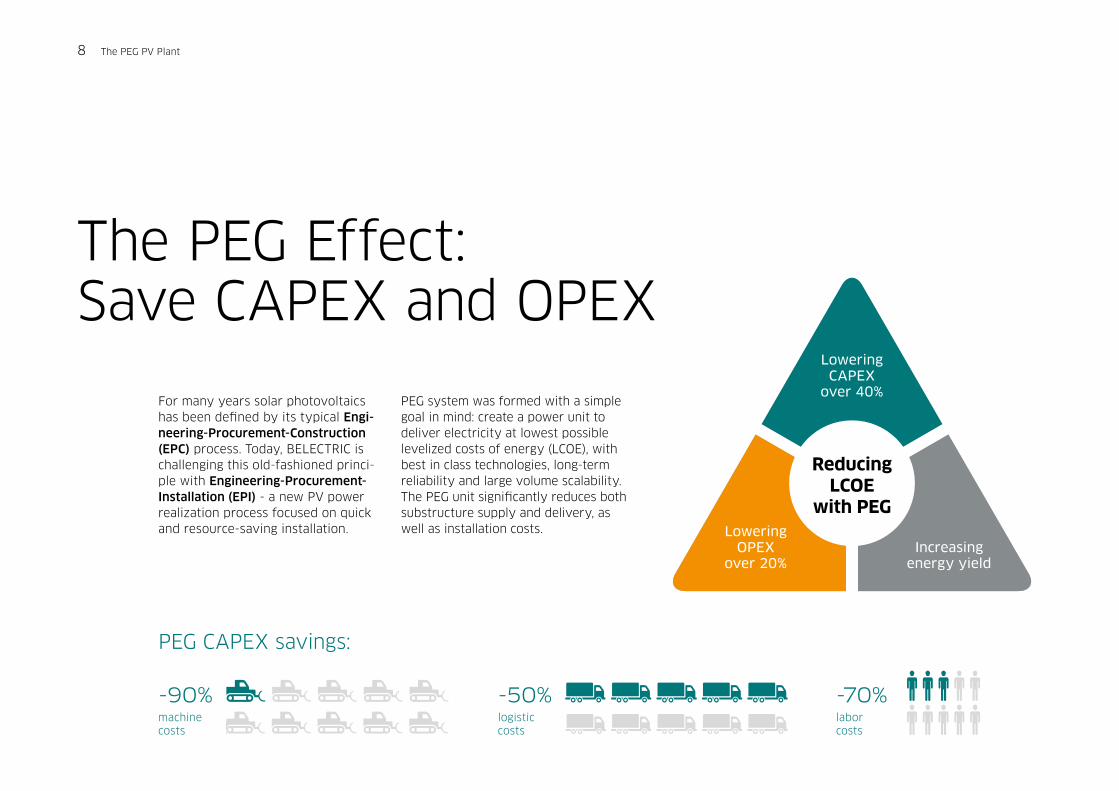
machine costs
logistic costs
labor costs
-90% -50% -70%
Lowering CAPEX
over 40%
Lowering OPEX
over 20%Increasing
energy yield
Reducing LCOE
with PEG
For many years solar photovoltaics has been defined by its typical Engi-neering-Procurement-Construction (EPC) process. Today, BELECTRIC is challenging this old-fashioned princi-ple with Engineering-Procurement- Installation (EPI) - a new PV power realization process focused on quick and resource-saving installation.
PEG system was formed with a simple goal in mind: create a power unit to deliver electricity at lowest possible levelized costs of energy (LCOE), with best in class technologies, long-term reliability and large volume scalability. The PEG unit significantly reduces both substructure supply and delivery, as well as installation costs.
The PEG Effect:Save CAPEX and OPEX
PEG CAPEX savings:
8 The PEG PV Plant
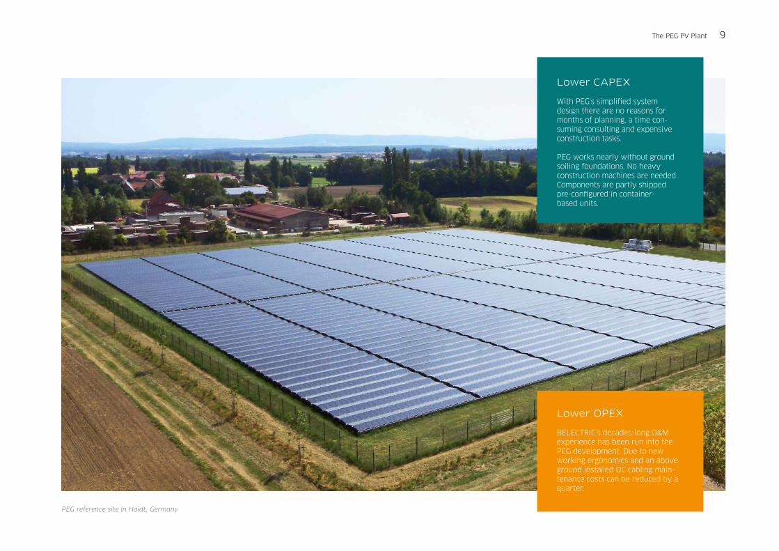
PEG reference site in Haidt, Germany
Lower CAPEX With PEG‘s simplified system design there are no reasons for months of planning, a time con-suming consulting and expensive construction tasks.
PEG works nearly without ground soiling foundations. No heavy construction machines are needed. Components are partly shipped pre-configured in container- based units.
Lower OPEX BELECTRIC‘s decades-long O&M experience has been run into the PEG development. Due to new working ergonomics and an above ground installed DC cabling main-tenance costs can be reduced by a quarter.
The PEG PV Plant 9
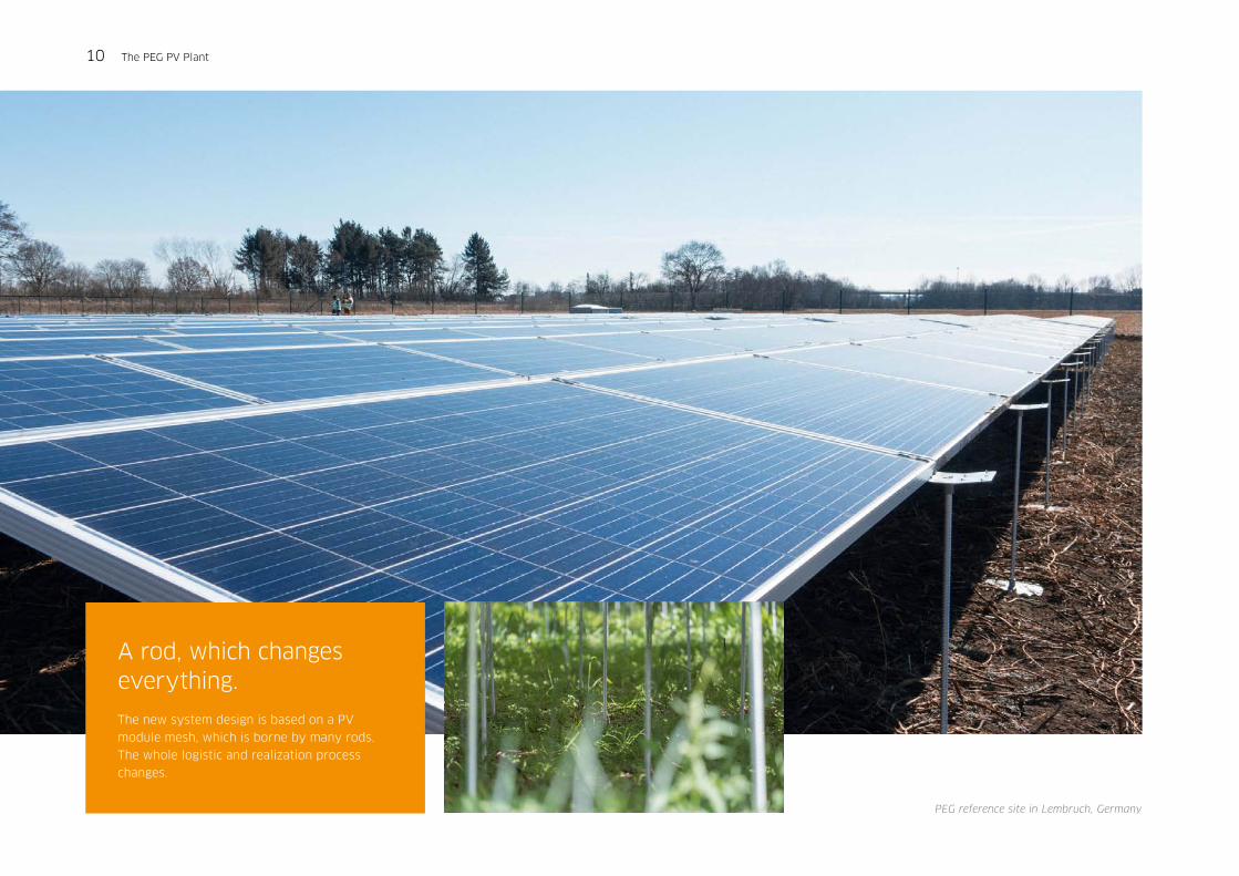
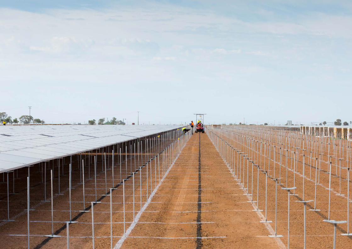
A rod, which changes everything.
The new system design is based on a PV
module mesh, which is borne by many rods.
The whole logistic and realization process
changes.
PEG reference site in Lembruch, Germany
10 The PEG PV Plant
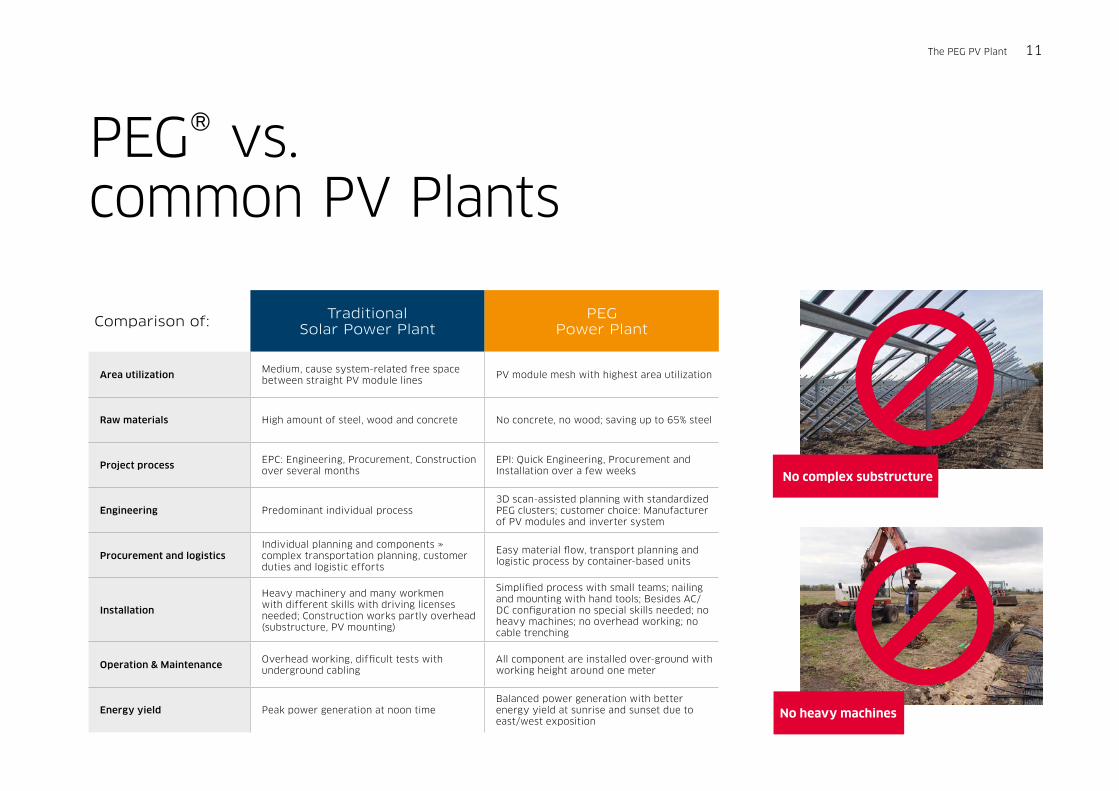
PEG® vs. common PV Plants
Comparison of: Traditional Solar Power Plant
PEG Power Plant
Area utilizationMedium, cause system-related free space between straight PV module lines
PV module mesh with highest area utilization
Raw materials High amount of steel, wood and concrete No concrete, no wood; saving up to 65% steel
Project processEPC: Engineering, Procurement, Construction over several months
EPI: Quick Engineering, Procurement and Installation over a few weeks
Engineering Predominant individual process3D scan-assisted planning with standardized PEG clusters; customer choice: Manufacturer of PV modules and inverter system
Procurement and logisticsIndividual planning and components » complex transportation planning, customer duties and logistic efforts
Easy material flow, transport planning and logistic process by container-based units
Installation
Heavy machinery and many workmen with different skills with driving licenses needed; Construction works partly overhead (substructure, PV mounting)
Simplified process with small teams; nailing and mounting with hand tools; Besides AC/DC configuration no special skills needed; no heavy machines; no overhead working; no cable trenching
Operation & MaintenanceOverhead working, difficult tests with underground cabling
All component are installed over-ground with working height around one meter
Energy yield Peak power generation at noon timeBalanced power generation with better energy yield at sunrise and sunset due to east/west exposition
No complex substructure
The PEG PV Plant 11
No heavy machines
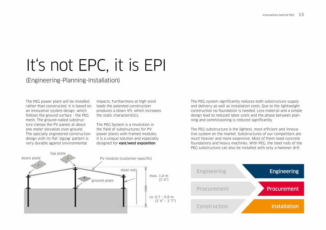
steel rod
PV module (customer-specific) down plate
ground plate
top plate
It‘s not EPC, it is EPI (Engineering-Planning-Installation)
The PEG power plant will be installed rather than constructed. It is based on an innovative system design, which follows the ground surface - the PEG mesh. The ground-nailed substruc-ture clamps the PV panels at about one meter elevation over-ground. The specially engineered construction design with its flat ‘zigzag‘ pattern is very durable against environmental
impacts. Furthermore at high wind loads the patented construction produces a down-lift, which increases the static characteristics.
The PEG System is a revolution in the field of substructures for PV power plants with framed modules. It is a unique solution and especially designed for east/west exposition.
The PEG system significantly reduces both substructure supply and delivery as well as installation costs. Due to the lightweight construction no foundation is needed. Less material and a simple design lead to reduced labor costs and the phase between plan-ning and commissioning is reduced significantly.
The PEG substructure is the lightest, most efficient and innova-tive system on the market. Substructures of our competitors are much heavier and more expensive. Most of them need concrete foundations and heavy machines. With PEG, the steel rods of the PEG substructure can also be installed with only a hammer drill.
Engineering
Procurement
InstallationConstruction
Procurement
Engineeringmax. 1.0 m
(3´4”)
ca. 0.7 – 0.8 m (2´4” – 2´7”)
Innovations behind PEG 13
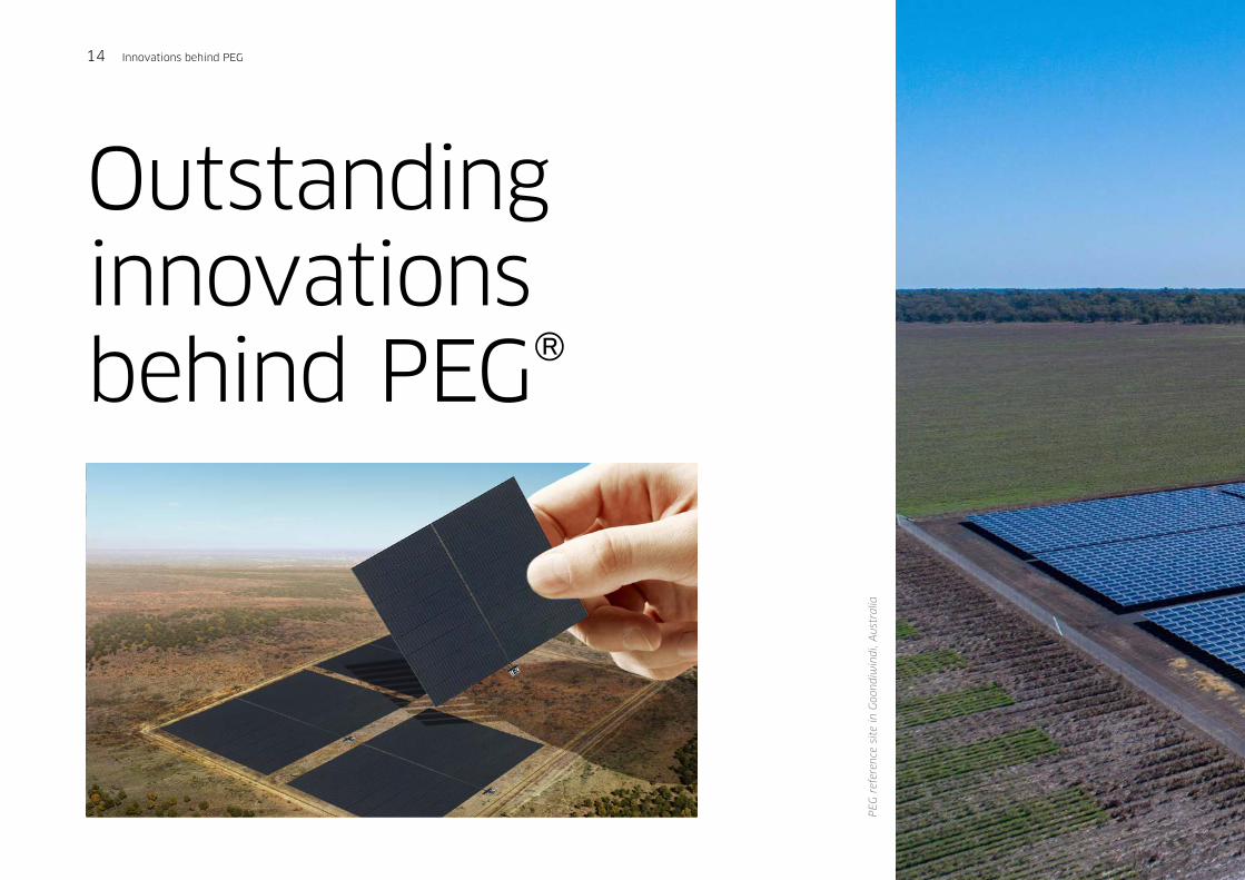
Outstanding innovationsbehind PEG®
PEG r
efer
ence
site
in G
oon
diw
indi,
Aus
tralia
14 Innovations behind PEG
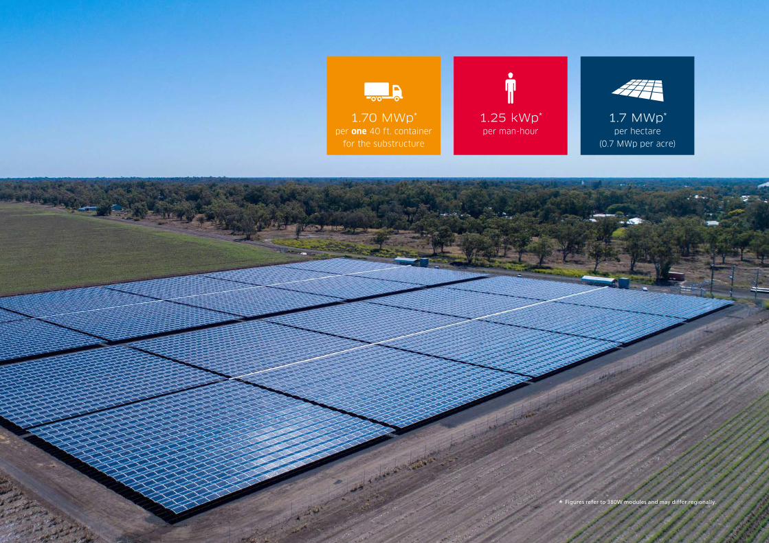
per one 40 ft. container
for the substructure
1.70 MWp* per hectare
(0.7 MWp per acre)
1.7 MWp*
per man-hour
1.25 kWp*
* Figures refer to 380W modules and may differ regionally.
90
80
70
60
50
40
30
20
10
0
% o
f no
min
al p
ower
4 6 8 10 12 14 16 18 20 22
time of day
South
East/West
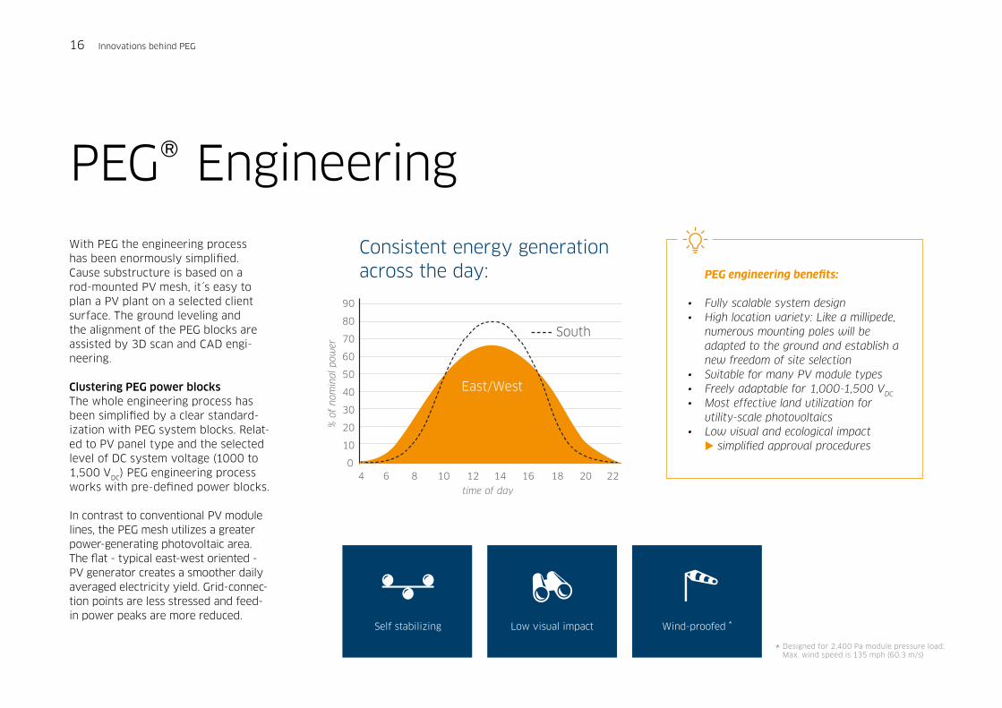
PEG® Engineering With PEG the engineering process has been enormously simplified. Cause substructure is based on a rod-mounted PV mesh, it´s easy to plan a PV plant on a selected client surface. The ground leveling and the alignment of the PEG blocks are assisted by 3D scan and CAD engi-neering.
Clustering PEG power blocksThe whole engineering process has been simplified by a clear standard-ization with PEG system blocks. Relat-ed to PV panel type and the selected level of DC system voltage (1000 to 1,500 VDC) PEG engineering process works with pre-defined power blocks.
In contrast to conventional PV module lines, the PEG mesh utilizes a greater power-generating photovoltaic area. The flat - typical east-west oriented - PV generator creates a smoother daily averaged electricity yield. Grid-connec-tion points are less stressed and feed-in power peaks are more reduced.
* Designed for 2,400 Pa module pressure load; Max. wind speed is 135 mph (60.3 m/s)
Self stabilizing Wind-proofed *Low visual impact
Consistent energy generation across the day: PEG engineering benefits:
• Fully scalable system design• High location variety: Like a millipede, numerous mounting poles will be adapted to the ground and establish a new freedom of site selection• Suitable for many PV module types • Freely adaptable for 1,000-1,500 VDC
• Most effective land utilization for utility-scale photovoltaics• Low visual and ecological impact simplified approval procedures
16 Innovations behind PEG

The revolution in utility-scale PV power: Best-in-class area utilization of 1.7 MWp* per hectare(0.7 MWp per acre)
Most effective land utilization.
Low visual impact.
Full scalable from 10 kWp to MWs.
* Figures refer to 380W modules and may differ regionally.
Innovations behind PEG 17

logistic costs
-50%
Reduced raw materials.
No concrete foundations.
Unit-based packaging.
No construction vehicles.
18 Innovations behind PEG
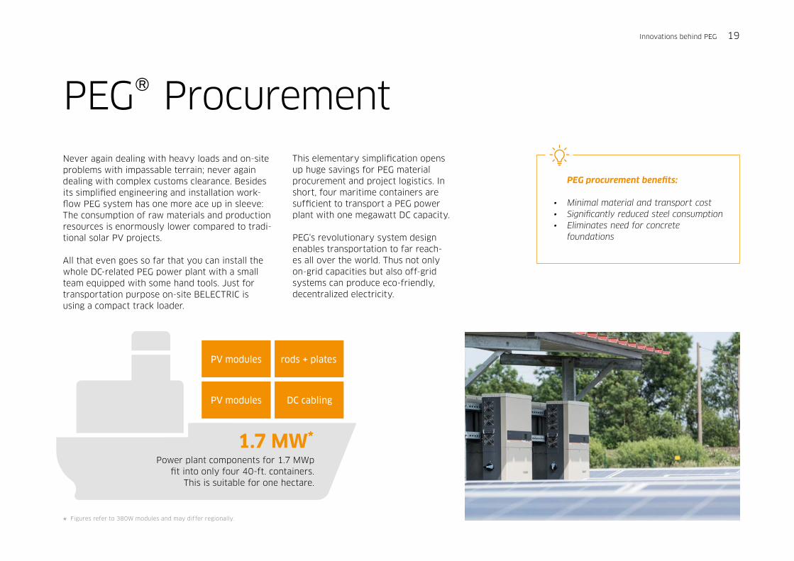
PV modules rods + plates
PV modules DC cabling
1.7 MW*
PEG® Procurement Never again dealing with heavy loads and on-site problems with impassable terrain; never again dealing with complex customs clearance. Besides its simplified engineering and installation work-flow PEG system has one more ace up in sleeve: The consumption of raw materials and production resources is enormously lower compared to tradi-tional solar PV projects.
All that even goes so far that you can install the whole DC-related PEG power plant with a small team equipped with some hand tools. Just for transportation purpose on-site BELECTRIC is using a compact track loader.
This elementary simplification opens up huge savings for PEG material procurement and project logistics. In short, four maritime containers are sufficient to transport a PEG power plant with one megawatt DC capacity.
PEG‘s revolutionary system design enables transportation to far reach-es all over the world. Thus not only on-grid capacities but also off-grid systems can produce eco-friendly, decentralized electricity.
Power plant components for 1.7 MWp fit into only four 40-ft. containers.
This is suitable for one hectare.
PEG procurement benefits:
• Minimal material and transport cost• Significantly reduced steel consumption• Eliminates need for concrete foundations
* Figures refer to 380W modules and may differ regionally.
Innovations behind PEG 19

PEG® InstallationThe PEG power plant installation is based on a quick nailing process. Only four workmen are necessary to start-up a PEG power plant installation. Like an ink-based office printer is completing a print out, the PEG power plant will be installed line-by-line. In contrast to traditional PV power plant suppliers the working process does not depend on heavy working machines or vehicles. Most works can be run at waist level to ensure an ergo-nomic and HSE optimized working environment.
Despite the high-level of standardization the PEG system design is compatible to many PV panel manufacturers. For best individu-alism the customer can choose his favored panel type.
Easy and fast installation with PEG: • Installation speed: 0.8 man-hour per
KWp • Simple installation process: - no need for special construction requirements and heavy machinery - no concrete foundations - no cable trenches• Reduced risks and cost in terms of HSE• All components installed over-ground (no underground works necessary)• Ergonomic working height: 0.6 m to 1.2 m (2 to 4 feet)• PEG will be installed line by line with an easy nailing placement process • Simple and residue-free dismantling after project life, in case of different land use designation
per man-hour
1.25 kWp*
* Figures refer to 380W modules and may differ regionally.
20 Innovations behind PEG
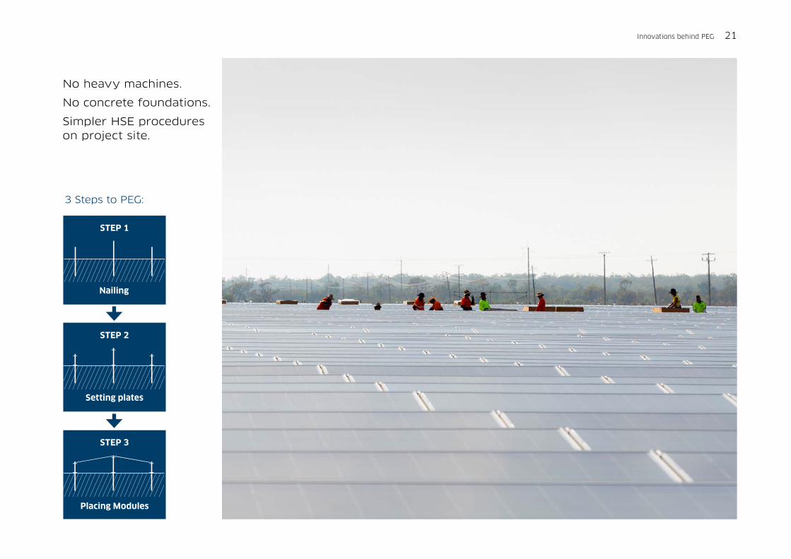
Setting plates
Placing Modules
3 Steps to PEG:
STEP 2
STEP 3
Nailing
STEP 1
No heavy machines.
No concrete foundations.
Simpler HSE procedures on project site.
Innovations behind PEG 21

Operation and Maintenance
22 Operation and Maintenance
BELECTRIC O&M services help to support continu-ous PV plant operation, giving higher energy yield and therefore high return on investment across life-cycle. From daily operation, routine and sched-uled maintenance, to outage services our service team meets the demands of customers’ individual operational and maintenance models comprising as risk sharing mechanisms.
• Remote monitoring and diagnostics • Maintenance• Spare parts and obsolescence management• Warranty extensions• Response time guarantees• Availability guarantees
While developing the new PEG system our engi-neers considering BELECTRIC‘s know-how and long-time experience in the operation and maintenance of large-scale PV power plants. In result PEG‘s low substructure with overground DC cabling allows a simplified site inspection.
Besides, BELECTRIC introduces a new, smart O&M work-flow, especially a robot-assisted PV module cleaning process, an optional PEG mowing robot and an O&M service bench to access single PV modules on-site.
The PID reduction technology and long-term guarantees of all PEG integrated components safe a reliable operation.
Quick and easy site inspections: • Low substructure allows easy site inspections• No parts installed under ground• Quick and easy full-string check ups• PV module servicing with PEG working bench
PV site care
• Automated PV module cleaning robot• Robot-assisted turf mowing (in normal case not necessary with PEG)
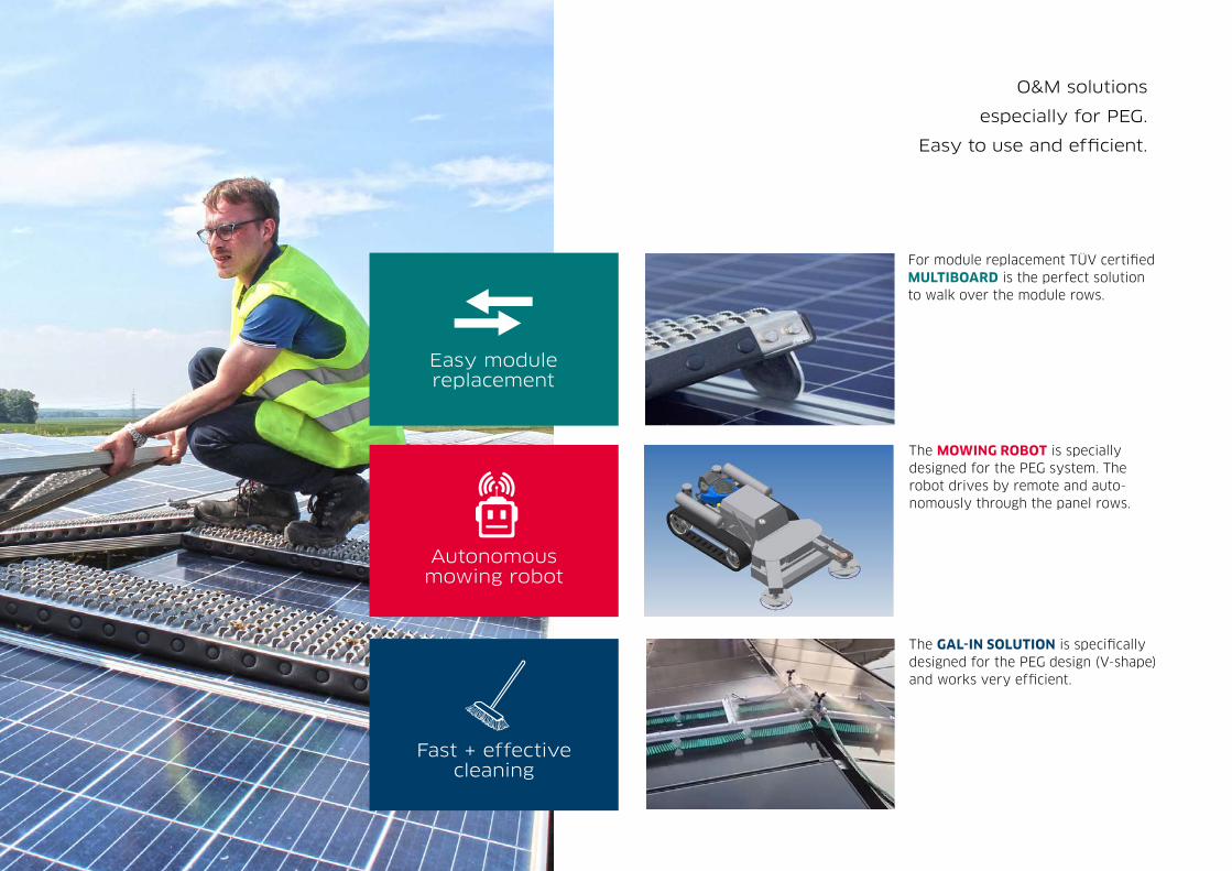
O&M solutions
especially for PEG.
Easy to use and efficient.
Fast + effective cleaning
Autonomous mowing robot
Easy module replacement
The GAL-IN SOLUTION is specifically designed for the PEG design (V-shape) and works very efficient.
The MOWING ROBOT is specially designed for the PEG system. The robot drives by remote and auto-nomously through the panel rows.
For module replacement TÜV certified MULTIBOARD is the perfect solution to walk over the module rows.
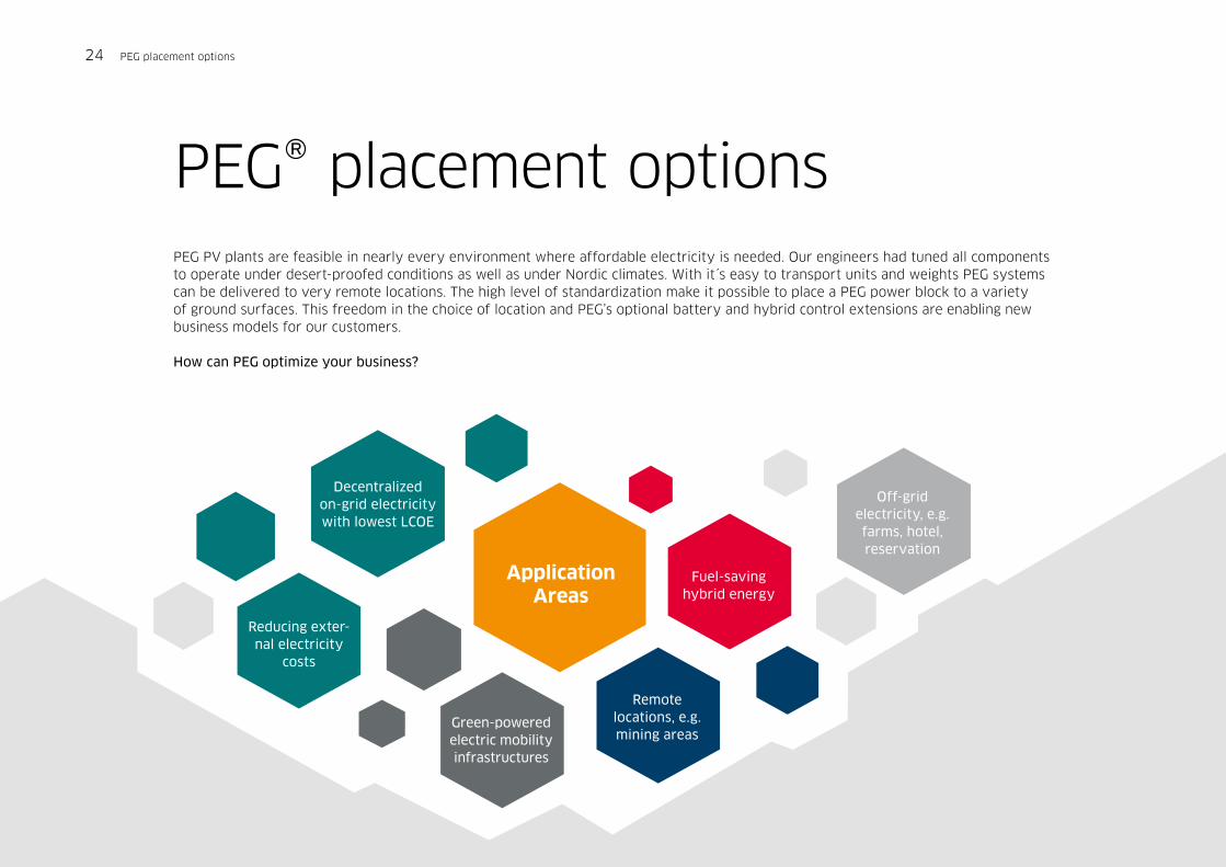
PEG® placement optionsPEG PV plants are feasible in nearly every environment where affordable electricity is needed. Our engineers had tuned all components to operate under desert-proofed conditions as well as under Nordic climates. With it´s easy to transport units and weights PEG systems can be delivered to very remote locations. The high level of standardization make it possible to place a PEG power block to a variety of ground surfaces. This freedom in the choice of location and PEG’s optional battery and hybrid control extensions are enabling new business models for our customers.
How can PEG optimize your business?
Decentralized on-grid electricity with lowest LCOE
Reducing exter-nal electricity
costs
Application Areas
Green-powered electric mobility infrastructures
Remotelocations, e.g. mining areas
Fuel-saving hybrid energy
Off-grid electricity, e.g. farms, hotel, reservation
24 PEG placement options
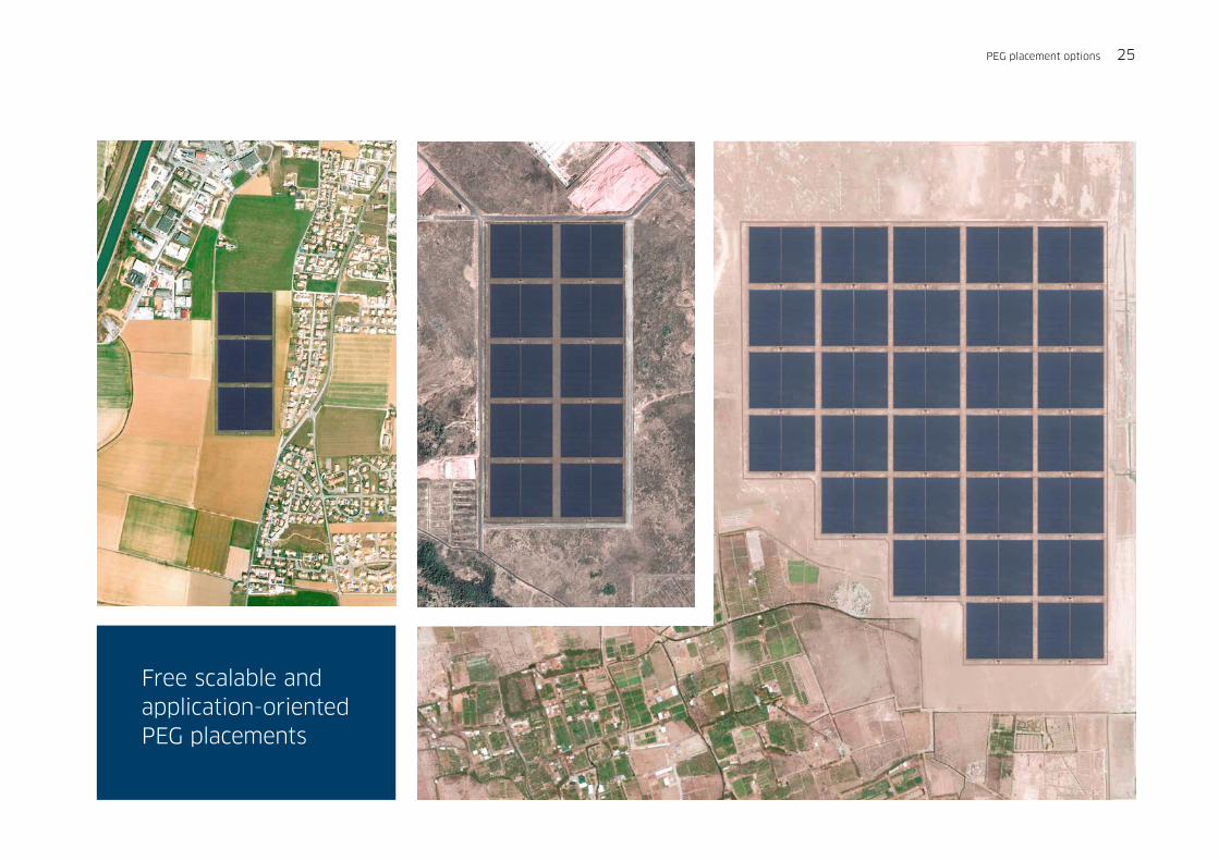
Free scalable and application-oriented PEG placements
PEG placement options 25

PEG® applicable: Battery Storage and Hybrid power
Besides its high solar PV expertise BELECTRIC develops industrial systems for battery storage and hybrid solutions. With these new technologies climate-friendly solar power will be combined with the benefits of fuel-based energy sources.
Lithium-Ion based battery storage and hybrid control units can be integrated into a PEG PV plant. The battery storage reacts on load and voltage variations in milliseconds. BELECTRIC’s Energy Buffer Unit (abbr. EBU) enables ancillary grid stabilization services like black start, island operation and virtual iner-tia. It can provide grid stabilization through primary frequency response, enhanced frequency response, RoCoF
response, load shifting, peak shaving. As BELECTRIC PEG, the LION EBU is designed for maximal scalability and flexibility. It can be adapted for today’s needs at local or national power grids, guaranteeing a stable grid, and even allowing more renewable energy in the near future.
Hybrid Island PowerFast response
Frequency Control Peak Shaving EV Charge
Battery and hybrid benefits:
• Highly standardized hybrid and battery power units compatible with PEG PV plant• Improve power quality at regional grid• Enables ancillary smart grid services• Independent electricity 24/7 with maximized use of fuel-less solar PV• Improve island and off-grid, micro-grid infrastructures
26 Battery and Hybrid Power
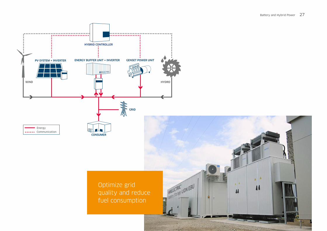
GENSET POWER UNIT
GRID
CONSUMER
WIND HYDRO
ENERGY BUFFER UNIT + INVERTERPV-SYSTEM + INVERTER
HYBRID CONTROLLER
Energy
Communication
Optimize grid quality and reduce fuel consumption
Battery and Hybrid Power 27

Solar energy is a gift from nature
Low ecological footprint in manufacturing, logistics and installation.
Low land consumption.
Completely dismantable PV plant.
28 Eco-friendly electricity
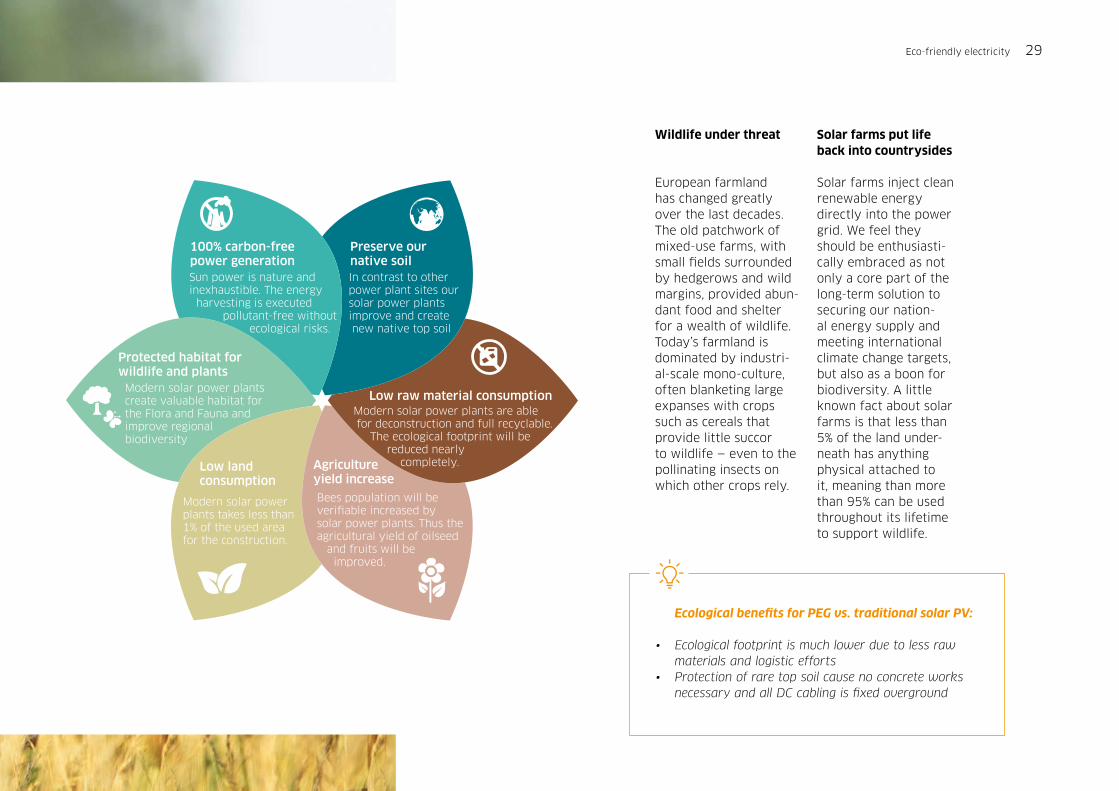
Preserve our native soilIn contrast to other power plant sites our solar power plants improve and create new native top soil
100% carbon-free power generation Sun power is nature and inexhaustible. The energy harvesting is executed pollutant-free without ecological risks.
Low raw material consumptionModern solar power plants are able for deconstruction and full recyclable. The ecological footprint will be reduced nearly completely.Low land
consumption
Modern solar power plants takes less than 1% of the used area for the construction.
Agriculture yield increase
Bees population will be veri�able increased by solar power plants. Thus the agricultural yield of oilseed and fruits will be improved.
Protected habitat for wildlife and plantsModern solar power plants create valuable habitat for the Flora and Fauna and improve regional biodiversity
Wildlife under threat
European farmland has changed greatly over the last decades. The old patchwork of mixed-use farms, with small fields surrounded by hedgerows and wild margins, provided abun-dant food and shelter for a wealth of wildlife. Today’s farmland is dominated by industri-al-scale mono-culture, often blanketing large expanses with crops such as cereals that provide little succorto wildlife — even to the pollinating insects on which other crops rely.
Solar farms put lifeback into countrysides
Solar farms inject clean renewable energy directly into the power grid. We feel they should be enthusiasti-cally embraced as not only a core part of the long-term solution to securing our nation-al energy supply and meeting international climate change targets, but also as a boon for biodiversity. A little known fact about solar farms is that less than 5% of the land under-neath has anything physical attached to it, meaning than more than 95% can be used throughout its lifetime to support wildlife.
Ecological benefits for PEG vs. traditional solar PV:
• Ecological footprint is much lower due to less raw materials and logistic efforts• Protection of rare top soil cause no concrete works necessary and all DC cabling is fixed overground
Eco-friendly electricity 29
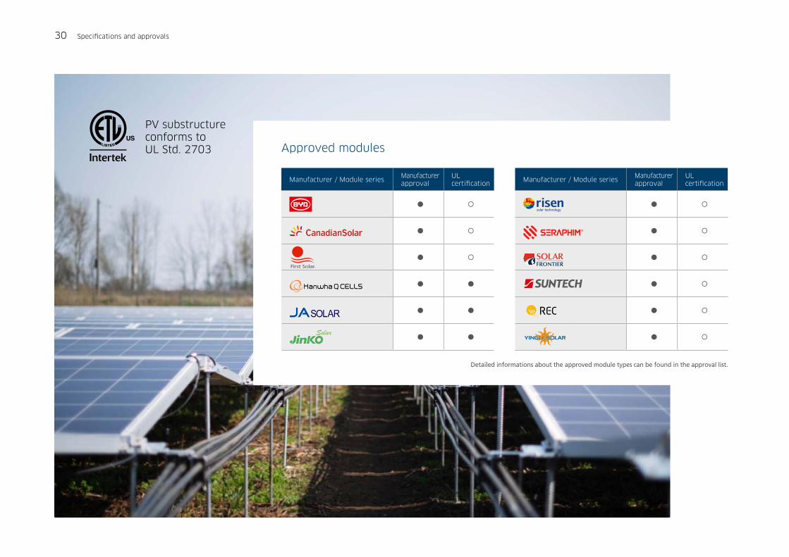
PV substructure conforms toUL Std. 2703
Manufacturer / Module seriesManufacturer approval
UL certification
Manufacturer / Module seriesManufacturer approval
UL certification
Detailed informations about the approved module types can be found in the approval list.
30 Specifications and approvals
Approved modules

Specifications and approvals
Orientation PV array
Patented 8° East-West, fixed tilt, aerodynamic proofed (patent-registered design)
BOM (Bill of material) 1.10 rods and 2.15 clips per module
Large volume scalability Any power plant capacity from at 10 kWp is possible
Durability
Hot deep galvanized steel rods and pre-galvanized steel plates.PV modules and clips based on corrosion-free aluminum and glass. All DC cabling components are weatherproof and UV resistant.
Wind loadsDesigned for 2,400Pa module pressure load; compliance with wind codes is TBD by local engineering company per wind region
Valid air temperature Up to 50°C, 122°F (up to 55°C, 131°F with Hot Climate Option)
Certifications
Clamping approval from module manufacturers.
Wind load certificate by local engineering firm in accordance with local wind codes.
The PEG substructure is UL certified.
Warranties
Warranty time has to be defined per project based on the site and soil conditions.
Functional warranty, excluding cosmetic issues like rust.
Standard warranty and geotechnical tests guidance documents available upon request.
Technical data
Land soil conditionCohesive (e.g. sandy-clay, clayey silt) and non- cohesive soil (e.g. sand or sand-gravel).
Upper soil layerNo rocks or underground infrastructure up to 1m (3´4“) below ground; rammed depth up to 0.8m (2´7“)
Site slopes
The PEG system can be installed on slopes of up to 4.5 deg.
In case the site slope is up to 2 deg, the rods should be vertical to the horizontal plane.
In case the slope is higher than 2 deg., the rods should be verti-cal to ground slope.
Requirements
Specifications and approvals 31

PEG® –Harvesting the Power of the Sun
BELECTRIC Solar & Battery GmbH is one of the most successful enterpris-es in the development and construc-tion of utility-scale solar PV power plants and battery storage systems. The company was established in 2001 and has been expanded to an inter-national group with activities on all continents since then.
BELECTRIC has constructed 300 solar PV power plants with around 2 GWp PV capacity. In addition, the compa-ny realized battery energy storage systems and hybrid power solutions, which combines different technolo-gies to autarkic systems. As one of the largest O&M providers globally, BELECTRIC’s full-integrated services provide continuous operation.
BELECTRIC Solar & Battery GmbH
Wadenbrunner Str. 10
97509 Kolitzheim, Germany
Phone +49 (9385) 9804 - 0
www.belectric.com
PEG
pro
duct b
roch
ure R
ev 1
0.3
_20
19
-07-0
3 E
NFigu
res refer to 3
80
W m
odules an
d m
ay d
iffer regionally.
All d
ata may
subje
ct to alteratio
ns an
d erro
rs.