perceptually uniform grayscale coding in the … uniform grayscale coding ... have a measured 1000:1...
TRANSCRIPT

1
Perceptually Uniform Grayscale CodingIn the Panavision Genesis®
Electronic Cinematography System
Authors: John Galt - PanavisionJames Pearman - Panavision

2
Although it is fashionable today to deprecate manyaspects of the NTSC television system such asinterlace, limited color space, limited dynamic rangeetc. the 1953NTSC system was a masterfulapplication of the limits of the technology availableto the video engineers in the middle of the 20thcentury. The most important principle employed bythe NTSC designers was that the camera’s imagingparameters would be defined by the displayparameters. This made perfect sense at the time sinceit ensured that the complex electronics would residein the camera enabling greater simplicity andtherefore lower cost in the display or television set.This principle persists to this day in many modernimaging systems that have nothing to do withtelevision. Why is this?

3
The simple answer is that the response to change inlight intensity of the human visual system is non-linear. The lightness response of the visual system isapproximated by a power function with a 0.4exponent. That is, an 18% gray card appears to theeye to be approximately half way between black andwhite.
Yx= 0.180.4 = 0.50 = 50%
By a happy coincidence, a CRT’s response is also apower function with an exponent of approximately2.5 requiring an input signal with an inverse value inorder to output linear light
1/2.5 = 0.4
4
Empirically an inverse value of 1/2.2 or 0.45 hasbeen standardized as the average slope of the mostrecent incarnation of this video signal definition asincorporated in ITU-R BT.709. The basic gammafunction embodied in this standard is almost identicalto the original 1953NTSC standard that required acamera output with the slope of a power function of0.45. This value is the reciprocal function of theCRT’s gamma function modified to include acompensation for dark surround viewing.

5
-0.2
0
0.2
0.4
0.6
0.8
1
1.2
0 0.2 0.4 0.6 0.8 1 1.2
Camera/CRT gamma
Gamma0.45Gamma2.2Gamma2.5CRT Light(2.2)CRT Light(2.5)
Rel
ativ
e Va
lue
Input
Average slope=1.125
Average slope=1.00

6
This would not be a sufficiently good reason tocontinue to use this fifty-year-old video standardwere it not for an additional property of this gammafunction:
Perceptual Uniformity
Because the inverse of the CRT’s gamma function issimilar to the visual lightness response powerfunction, data coded according to this function willmake perceptually optimum use of available bitdepth. However, tying the camera gamma to theCRT’s inverse gamma means, that the camera’sdynamic range and the CRT’s dynamic range arecoupled. Although high performance monitor canhave a measured 1000:1 contrast range, in a normalviewing environment, it is hard to exceed 100:1 dueto the limitations of the light output of large CRTs

7
The 1953 NTSC standard continues to influence boththe gamma function applied to what today areessentially linear camera signals and the parametersof the integral 3 x 3 matrix intended to match thecamera’s spectral analysis to the standard CRTphosphors. This strategy served the televisionindustry very well for the first 30 years since therewas no practical alternative to CRTs for displays andthe various camera tube technologies fromIconoscopes to Saticons had a limited dynamic rangethat was easily accommodated by the displaycharacteristics of CRT based televisions andmonitors.

8
With RCA’s introduction of CCD-1 in 1984, CCD imagers had come to television cameras. CCD’s would eventually have dynamic range capabilities that would exceed both the display dynamic range and the Rec.709 gamma function. In 2005 Panavision and Sony introduced Genesis®, a Super35 sized CCD imager camera with a dynamic range six times greater than that accommodated by the nominal Rec. 709 standard . This camera is presently being used on a number of major feature films being shot in different parts of the world.

9
10
Genesis® is not intended for direct view on television. The Genesis® electronic cinematography camera must capture the greatest scene dynamic range possible, recognizing that the recorded image will undergo extensive post-production before conversion to a variety of release formats and color spaces from 35mm print film to video and Electronic Cinema. An appropriate paradigm is the film camera negative that is capable of a much greater dynamic range that can be displayed by either print film or video displays.

11
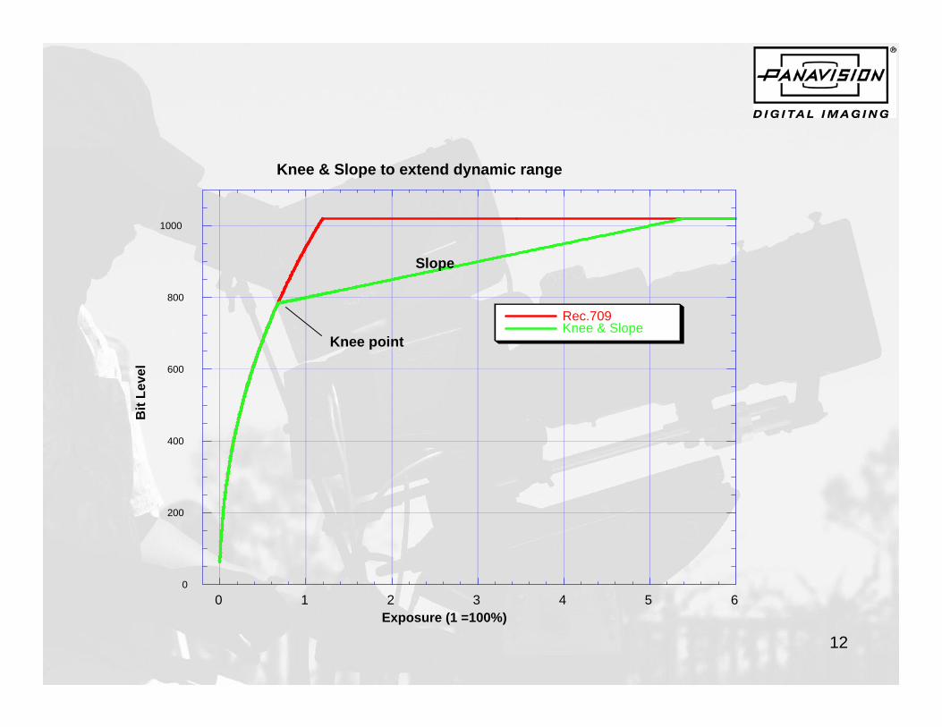
For a number of years, video camera manufacturershave provided a non-standard extension to thestandard video gamma function known as “knee” and“slope” control. The concept is that the basic 0.45power function could be modified by creating a newpoint gamma function or slope that could be initiatedat a particular video level or “knee point”.Unfortunately, this deviation from the 0.45 gammafunction introduced an unpredictable change in thecamera transfer characteristic that usually resulted intransitions in video levels that were often at thenominal skin tone levels and appeared unnatural
12
0
200
400
600
800
1000
0 1 2 3 4 5 6
Knee & Slope to extend dynamic range
Rec.709Knee & Slope
Bit
Leve
l
Exposure (1 =100%)
Knee point
Slope

13
With the introduction of the Genesis® camera utilizing a large area array CCD with an expanded dynamic range, we realized that it was time to divorce image acquisition from the display

14
The Genesis® camera incorporates a linear, 14 bit A/D converter, but the HDCAM-SR recorder can only support 10 bits per color. Linear quantization is perceptually inefficient and although the video gamma 0.45 power function results in a much better perceptual utilization of available bit depth than linear quantization the scaling of the video signal in the Rec. 709 standard only utilizes about 17% of the CCD saturation level to produce a 700 millivolt output. The maximum video output is limited to 760 millivolts, less than a 9% overhead; so defining an extended dynamic range must incorporate a re-scaling of the video signal such that the output of the camera will no longer be viewable on a standard monitor.

15
Others have faced this problem, Kodak developedCineon™, a 10 bit quasi-log system that has becomeubiquitous within the Electronic Cinema and DigitalIntermediate post community.
Thomson developed Filmstream™ for their Vipercamera.
Panavision has now developed yet another tool forElectronic Cinematography production and post-production.
May we introduce….

16
PANALOG™

17
PANALOG™ is a perceptually uniform transfer characteristic that internally transforms the 14 bit per color linear output of the Genesis® A/D converters into a quasi-logarithmic 10 bit per color signal that enables the RGB camera signal to be recorded on 10 bit recorders including, but not limited to, the dockable HDCAM-SR1 portable VTR.

18
PANALOG™ can readily be transferred back to the linearlight domain to facilitate post-production processes such asimage compositing, color matrix transforms and other colorcorrections that are best done in the linear light domain.
PANALOG™ data, without any transformations beingnecessary, can also be processed through existing telecine typecolor correctors.
PANALOG™ LUTs and transformation data will soon befreely available and downloadable from the Panavision website

19
The following graph shows PANALOG™, Rec.709 and Cineon™ in Log10 space. Cineon™ is included because a number of post facilities have attempted to use this familiar toolset. Although it is relatively simple to convert PANALOG™ to Cineon™, this will result in a reduction of the number of data levels available due to the indeterminate dynamic range of Cineon™ data. An important aspect of PANALOG™ is that it makes the maximum use of the quantizing levels available to express the full dynamic range of Genesis®.

20
0
128
256
384
512
640
768
896
1024
0.001 0.010 0.100 1.000 10.000
Exposure (
Panalo
Cineon
Rec709
Panalog™
Cineon™
Rec709

21
The next graph shows PANALOG™ (this time withlinear axes) overlaid with several perceptuallyuniform curves. The 0.53% increment is the best fitto PANALOG™.

22
0
128
256
384
512
640
768
896
1024
0 1 2 3 4 5 6
Panalog
Perceptual 0
Perceptual 0
Perceptual 1
Panalog™
Perceptual 0.53%
Perceptual 0.50%
Perceptual 1.00%
23
The next graph shows PANALOG™, Rec.709, Rec.709 with knee and slope and Cineon™, again in linear space. Due to its lower slope, Cineon™ has fewer code values therefore poorer quantizing than PANALOG™ applied to Genesis®’ dynamic range.

24
0
128
256
384
512
640
768
896
1024
0.0000 1.0000 2.0000 3.0000 4.0000 5.0000 6.0000
Exposu
Panalog
Cineon
Rec709
Rec709/Knee&S
Panalog™
Cineon™
Rec709
Rec709/Knee & Slope

25
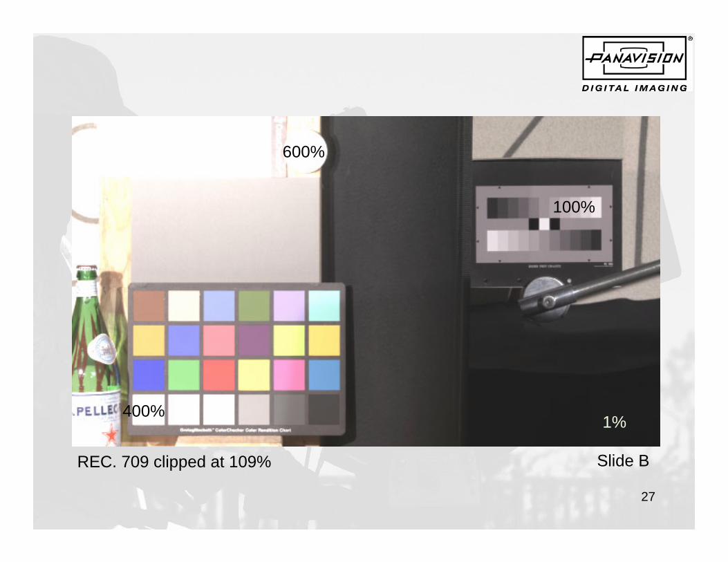
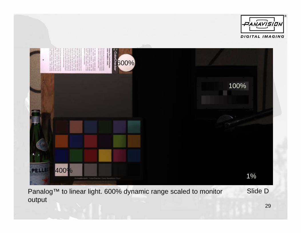
The following slides are Genesis® frames from a high dynamic range image. The percentage numbers are linear reflectance values. The 600% is five stops over 18% gray, 1% is four stops under 18% gray. Slide A is the unprocessed PANALOG™ output of Genesis® Slide B is a normal Rec. 709 image Slide C is processed through the Panavision Display Processor. The Display Processor enables the cinematographer to modify the transfer characteristic for display purposes only. Slide D is PANALOG™ converted to linear light space scaled to display 600% dynamic range. Slide D is PANALOG™ converted to linear light space with scaled to display 100% dynamic range.

26
600%
100%
Genesis® camera Panalog™ output
1%400%
Slide A
27
600%
100%
REC. 709 clipped at 109%
1%400%
Slide B

28
600%
100%
REC. 709 Through Panavision Display Processor (soft clip)
1%400%
Slide C
29
600%
1%
100%
Panalog™ to linear light. 600% dynamic range scaled to monitor output
400%
Slide D

30
600%
1%
100%
Panalog™ to linear light. 100% dynamic range scaled to monitor output
400%
Slide E
31
In conclusion, PANALOG™ is a perceptually uniform transfer characteristic that is designed to replace Rec. 709 gamma in high dynamic range digital cameras such as Genesis®. PANALOG™ separates the display function from the camera processor and therefore requires an external device such as the Panavision Display Processor to be introduced between the camera and the display. PANALOG™ enables wide dynamic range Digital Intermediate processes to be performed in linear light space while minimizing quantizing errors. PANALOG™ data can also be processed in standard telecine color correctors without the need for custom LUTs.