performance of hybrid mse/soil nail walls using numerical ... · performance of hybrid mse/soil...
TRANSCRIPT

HBRC Journal (2016) 12, 63–70
Housing and Building National Research Center
HBRC Journal
http://ees.elsevier.com/hbrcj
Performance of hybrid MSE/Soil Nail walls
using numerical analysis and limit equilibrium
approaches
E-mail address: [email protected]
Peer review under responsibility of Housing and Building National
Research Center.
Production and hosting by Elsevier
1687-4048 ª 2014 Production and hosting by Elsevier B.V. on behalf of Housing and Building National Research Center.
http://dx.doi.org/10.1016/j.hbrcj.2014.06.012
M. Rabie
Civil Engineering Dept., Helwan University, Cairo, Egypt
Received 22 April 2014; revised 1 June 2014; accepted 18 June 2014
KEYWORDS
Hybrid wall;
MSE/Soil Nail wall;
Soil nailing;
Numerical analysis;
Limit equilibrium
Abstract MSE/Soil Nail hybrid earth retaining walls provide a more economical design for appli-
cations in cut/fill situations than the traditionally used full height MSE and drilled shaft retaining
walls. MSE/Soil Nail hybrid earth retaining walls use a soil nailed wall in the cut section and an
MSE wall in the fill section. The paper demonstrates the results of instrumentation and monitoring
an MSE/Soil Nail hybrid retaining wall system. Innovative 2D finite element models were used to
simulate the behavior of the hybrid retaining wall system. The paper describes the philosophy of
design of hybrid MSE/Soil Nail walls and the outline of circumstances which are favorable for such
walls. In order to evaluate the global Factor of Safety (FOS) of the soil nail wall portion using the
conventional limit-equilibrium design methods (LEM), two different methodologies to simulate the
effect of the upper MSE walls were proposed. The obtained results of numerical and limit equilib-
rium approaches as a design methodology are presented for such type of walls, in this paper.
The design of hybrid MSE/SN walls is complicated as it is a composite of two different reinforce-
ment techniques, traditional limit equilibrium approaches cannot be used alone for design of such
walls, it shall be supported by numerical methods for estimation of the global factor of safety and
failure surface. The limit equilibrium approaches can be used for the estimation of internal stability
and facing connection for both soil nails and mechanically stabilized walls.ª 2014 Production and hosting by Elsevier B.V. on behalf of Housing and Building National Research
Center.
Introduction
Highway construction projects often require retaining walls to
be built into ‘‘side hill’’ situations where the bottom portion ofthe wall is placed below the existing ground, and the top por-tion placed above. Traditional design solutions used in side hill(or cut/fill) conditions have involved full height MSE walls and
drilled shaft retaining walls. When full height MSE walls areused, significant amount of earth material must be removed
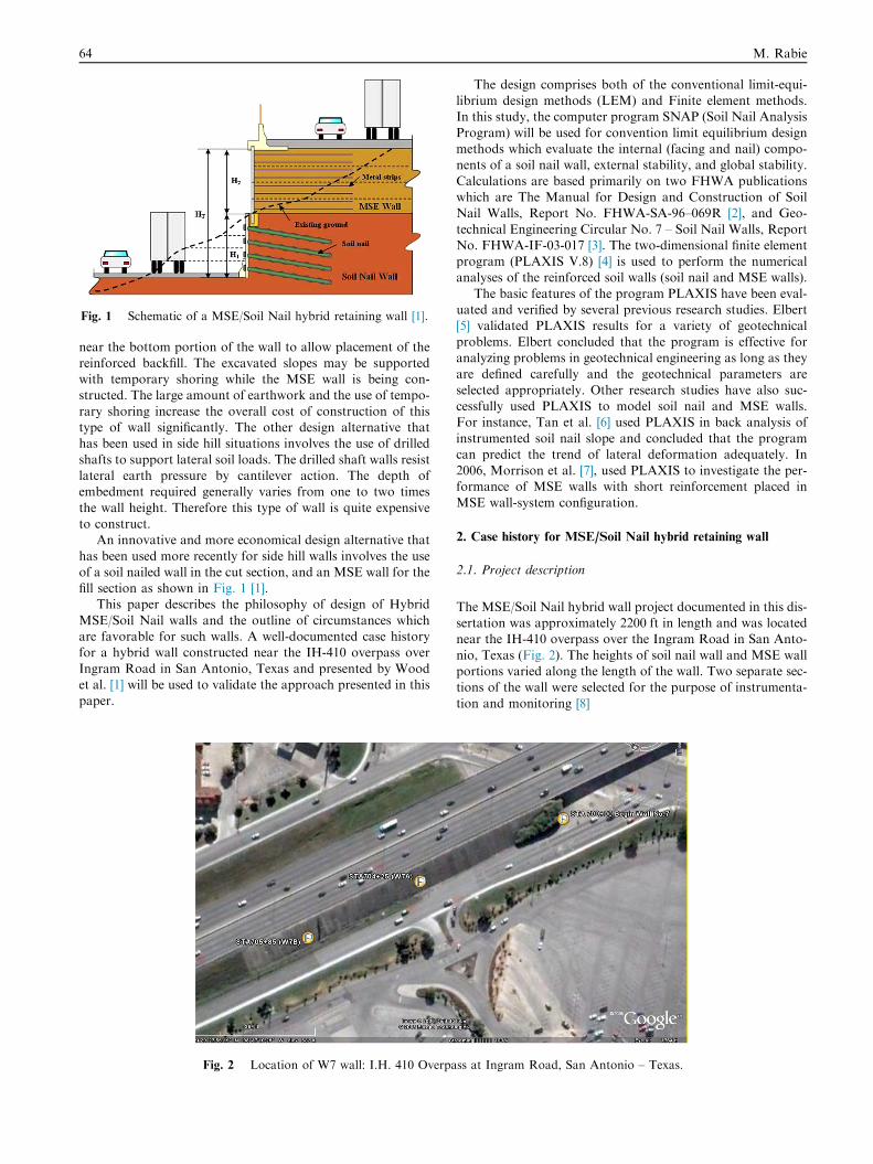
Fig. 1 Schematic of a MSE/Soil Nail hybrid retaining wall [1].
64 M. Rabie
near the bottom portion of the wall to allow placement of thereinforced backfill. The excavated slopes may be supportedwith temporary shoring while the MSE wall is being con-structed. The large amount of earthwork and the use of tempo-
rary shoring increase the overall cost of construction of thistype of wall significantly. The other design alternative thathas been used in side hill situations involves the use of drilled
shafts to support lateral soil loads. The drilled shaft walls resistlateral earth pressure by cantilever action. The depth ofembedment required generally varies from one to two times
the wall height. Therefore this type of wall is quite expensiveto construct.
An innovative and more economical design alternative that
has been used more recently for side hill walls involves the useof a soil nailed wall in the cut section, and an MSE wall for thefill section as shown in Fig. 1 [1].
This paper describes the philosophy of design of Hybrid
MSE/Soil Nail walls and the outline of circumstances whichare favorable for such walls. A well-documented case historyfor a hybrid wall constructed near the IH-410 overpass over
Ingram Road in San Antonio, Texas and presented by Woodet al. [1] will be used to validate the approach presented in thispaper.
Fig. 2 Location of W7 wall: I.H. 410 Overpa
The design comprises both of the conventional limit-equi-librium design methods (LEM) and Finite element methods.In this study, the computer program SNAP (Soil Nail Analysis
Program) will be used for convention limit equilibrium designmethods which evaluate the internal (facing and nail) compo-nents of a soil nail wall, external stability, and global stability.
Calculations are based primarily on two FHWA publicationswhich are The Manual for Design and Construction of SoilNail Walls, Report No. FHWA-SA-96–069R [2], and Geo-
technical Engineering Circular No. 7 – Soil Nail Walls, ReportNo. FHWA-IF-03-017 [3]. The two-dimensional finite elementprogram (PLAXIS V.8) [4] is used to perform the numericalanalyses of the reinforced soil walls (soil nail and MSE walls).
The basic features of the program PLAXIS have been eval-uated and verified by several previous research studies. Elbert[5] validated PLAXIS results for a variety of geotechnical
problems. Elbert concluded that the program is effective foranalyzing problems in geotechnical engineering as long as theyare defined carefully and the geotechnical parameters are
selected appropriately. Other research studies have also suc-cessfully used PLAXIS to model soil nail and MSE walls.For instance, Tan et al. [6] used PLAXIS in back analysis of
instrumented soil nail slope and concluded that the programcan predict the trend of lateral deformation adequately. In2006, Morrison et al. [7], used PLAXIS to investigate the per-formance of MSE walls with short reinforcement placed in
MSE wall-system configuration.
2. Case history for MSE/Soil Nail hybrid retaining wall
2.1. Project description
The MSE/Soil Nail hybrid wall project documented in this dis-sertation was approximately 2200 ft in length and was locatednear the IH-410 overpass over the Ingram Road in San Anto-
nio, Texas (Fig. 2). The heights of soil nail wall and MSE wallportions varied along the length of the wall. Two separate sec-tions of the wall were selected for the purpose of instrumenta-
tion and monitoring [8]
ss at Ingram Road, San Antonio – Texas.
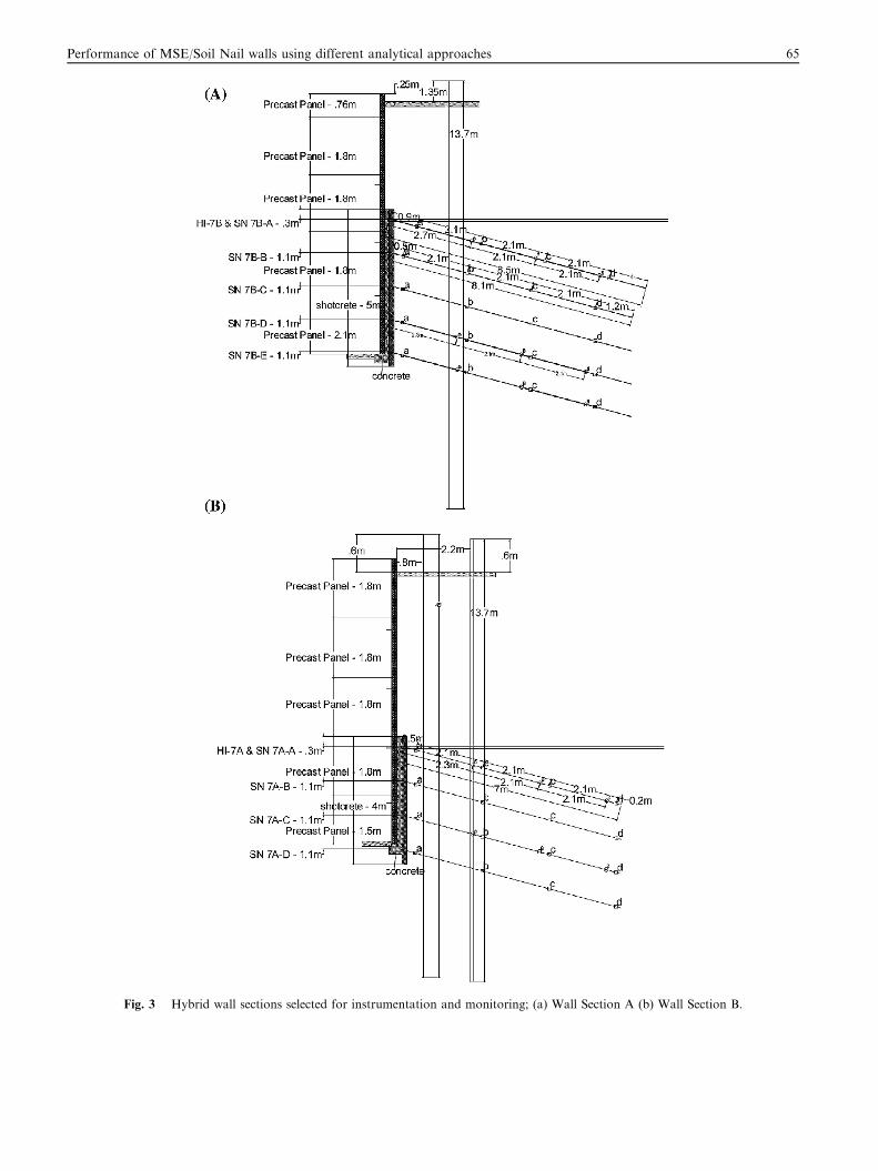
Fig. 3 Hybrid wall sections selected for instrumentation and monitoring; (a) Wall Section A (b) Wall Section B.
Performance of MSE/Soil Nail walls using different analytical approaches 65
(a) Wall 7 Section A (b) Wall 7 Section B
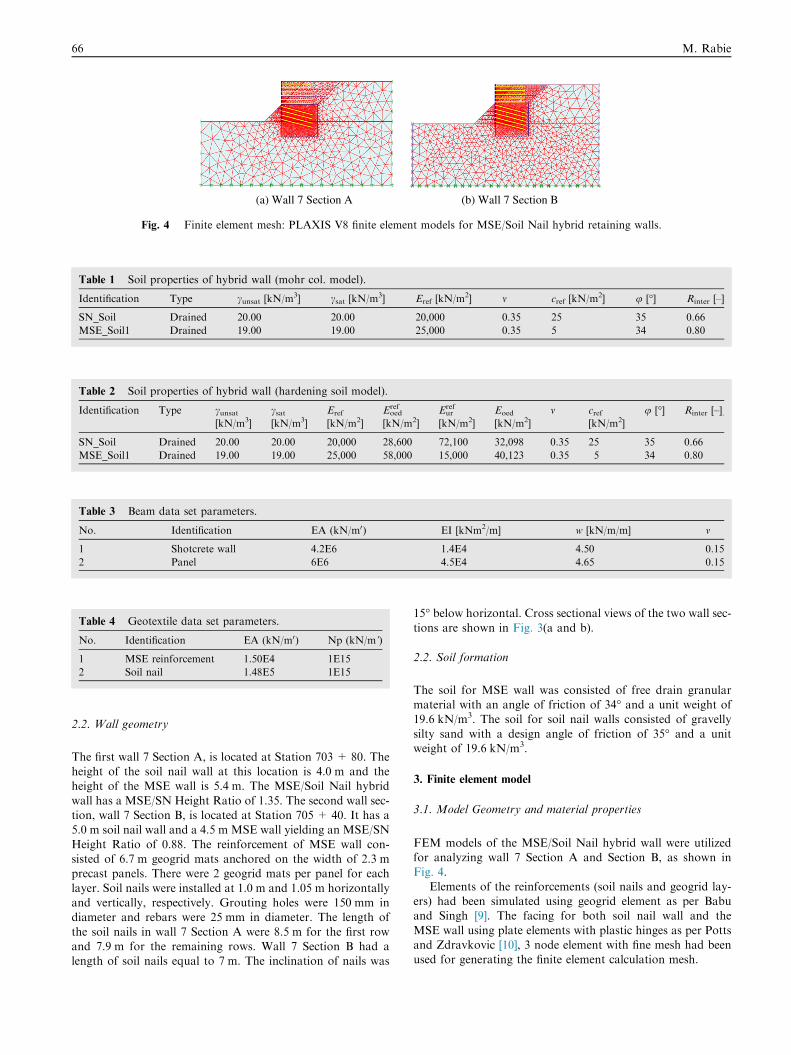
Fig. 4 Finite element mesh: PLAXIS V8 finite element models for MSE/Soil Nail hybrid retaining walls.
Table 1 Soil properties of hybrid wall (mohr col. model).
Identification Type cunsat [kN/m3] csat [kN/m3] Eref [kN/m2] m cref [kN/m2] u [�] Rinter [–]
SN_Soil Drained 20.00 20.00 20,000 0.35 25 35 0.66
MSE_Soil1 Drained 19.00 19.00 25,000 0.35 5 34 0.80
Table 3 Beam data set parameters.
No. Identification EA (kN/m0) EI [kNm2/m] w [kN/m/m] m
1 Shotcrete wall 4.2E6 1.4E4 4.50 0.15
2 Panel 6E6 4.5E4 4.65 0.15
Table 4 Geotextile data set parameters.
No. Identification EA (kN/m0) Np (kN/m’)
1 MSE reinforcement 1.50E4 1E15
2 Soil nail 1.48E5 1E15
Table 2 Soil properties of hybrid wall (hardening soil model).
Identification Type cunsat[kN/m3]
csat[kN/m3]
Eref
[kN/m2]
Eoedref
[kN/m2]
Eurref
[kN/m2]
Eoed
[kN/m2]
m cref[kN/m2]
u [�] Rinter [–].
SN_Soil Drained 20.00 20.00 20,000 28,600 72,100 32,098 0.35 25 35 0.66
MSE_Soil1 Drained 19.00 19.00 25,000 58,000 15,000 40,123 0.35 5 34 0.80
66 M. Rabie
2.2. Wall geometry
The first wall 7 Section A, is located at Station 703 + 80. Theheight of the soil nail wall at this location is 4.0 m and theheight of the MSE wall is 5.4 m. The MSE/Soil Nail hybrid
wall has a MSE/SN Height Ratio of 1.35. The second wall sec-tion, wall 7 Section B, is located at Station 705 + 40. It has a5.0 m soil nail wall and a 4.5 m MSE wall yielding an MSE/SN
Height Ratio of 0.88. The reinforcement of MSE wall con-sisted of 6.7 m geogrid mats anchored on the width of 2.3 mprecast panels. There were 2 geogrid mats per panel for each
layer. Soil nails were installed at 1.0 m and 1.05 m horizontallyand vertically, respectively. Grouting holes were 150 mm indiameter and rebars were 25 mm in diameter. The length of
the soil nails in wall 7 Section A were 8.5 m for the first rowand 7.9 m for the remaining rows. Wall 7 Section B had alength of soil nails equal to 7 m. The inclination of nails was
15� below horizontal. Cross sectional views of the two wall sec-
tions are shown in Fig. 3(a and b).
2.2. Soil formation
The soil for MSE wall was consisted of free drain granularmaterial with an angle of friction of 34� and a unit weight of19.6 kN/m3. The soil for soil nail walls consisted of gravelly
silty sand with a design angle of friction of 35� and a unitweight of 19.6 kN/m3.
3. Finite element model
3.1. Model Geometry and material properties
FEM models of the MSE/Soil Nail hybrid wall were utilizedfor analyzing wall 7 Section A and Section B, as shown inFig. 4.
Elements of the reinforcements (soil nails and geogrid lay-ers) had been simulated using geogrid element as per Babuand Singh [9]. The facing for both soil nail wall and the
MSE wall using plate elements with plastic hinges as per Pottsand Zdravkovic [10], 3 node element with fine mesh had beenused for generating the finite element calculation mesh.
(a) External failure mode
(b) Internal failure mode
(c) Facing failure mode
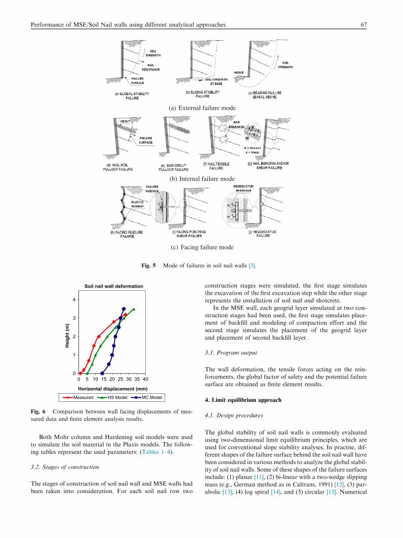
Fig. 5 Mode of failures in soil nail walls [3].
0
1
2
3
4
0 5 10 15 20 25 30 35 40
Hei
ght (
m)
Horizontal displacement (mm)
Soil nail wall deformation
Measured HS Model MC Model
Fig. 6 Comparison between wall facing displacements of mea-
sured data and finite element analysis results.
Performance of MSE/Soil Nail walls using different analytical approaches 67
Both Mohr column and Hardening soil models were usedto simulate the soil material in the Plaxis models. The follow-
ing tables represent the used parameters: (Tables 1–4).
3.2. Stages of construction
The stages of construction of soil nail wall and MSE walls had
been taken into consideration. For each soil nail row two
construction stages were simulated, the first stage simulatesthe excavation of the first excavation step while the other stage
represents the installation of soil nail and shotcrete.In the MSE wall, each geogrid layer simulated at two con-
struction stages had been used, the first stage simulates place-ment of backfill and modeling of compaction effort and the
second stage simulates the placement of the geogrid layerand placement of second backfill layer.
3.3. Program output
The wall deformation, the tensile forces acting on the rein-forcements, the global factor of safety and the potential failure
surface are obtained as finite element results.
4. Limit equilibrium approach
4.1. Design procedures
The global stability of soil nail walls is commonly evaluatedusing two-dimensional limit equilibrium principles, which areused for conventional slope stability analyses. In practise, dif-ferent shapes of the failure surface behind the soil nail wall have
been considered in various methods to analyze the global stabil-ity of soil nail walls. Some of these shapes of the failure surfacesinclude: (1) planar [11], (2) bi-linear with a two-wedge slipping
mass (e.g., German method as in Caltrans, 1991) [12], (3) par-abolic [13], (4) log spiral [14], and (5) circular [15]. Numerical

0
50
100
0 1 2 3 4 5 6 7 8Tens
ile fo
rce
(kN
)
Distance from facing (m)
Nail forcesSEC A Top row
Measured Results of finite element Results of LE
0
20
40
60
0 1 2 3 4 5 6 7 8Tens
ile fo
rce
(kN
)
Distance from facing (m)
Nail forcesSEC A second row
Measured Results of finite element Results of LE
0
10
20
30
40
50
0 1 2 3 4 5 6 7 8
Tens
ile fo
rce
(kN
)
Distance from facing (m)
Nail forcesSEC B Top row
Measured Results of finite element Results of LE
0
10
20
30
40
0 1 2 3 4 5 6 7 8
Tens
ile fo
rce
(kN
)
Distance from facing (m)
Nail forcesSEC B second row
Measured Results of finite element Results of LE
Fig. 7 Comparison between measured data, results of finite
element and limit equilibrium approaches.
68 M. Rabie
comparisons among different methods show that differences inthe geometry of the failure surface do not result in a significantdifference in the calculated factors of safety [16].
The conventional design of the soil nail wall is carried withreference to the allowable stress design procedure stated in the
(a) Wall 7 Section A
Fig. 8 Contour lines and potential failure surface of the fi
report of Federal Highway Administration for analyses, designand construction of soil nail walls [3].
The design includes analysis of external failure modes (such
as global stability and sliding stability), analysis of internalfailure modes (such as nail pullout failure and nail tensilestrength failure), design of permanent facing and verification
of important facing failure modes (such as facing flexure fail-ure and facing punching shear failure as shown in Fig. 5.
The deflection is not encountered in conventional limit
equilibrium approaches as the reinforced soil mass is treatedas rigid body.
4.2. Computer design program for soil nail walls
SNAP (Soil Nail Analysis Program) evaluates the internal (fac-ing and nail) components of a soil nail wall, external stability,and global stability. Calculations are based primarily on two
FHWA publications: (1) TheManual for Design and Construc-tion of Soil Nail Walls, Report No. FHWA-SA-96-069R, and(2) Geotechnical Engineering Circular No. 7 – Soil Nail Walls,
Report No. FHWA-IF-03-017.
4.3 Simulation of MSE wall
The upper portion of hybrid wall (MSE wall) is simulatedusing two different methodologies:
A)
� In the first method the MSE wall was illuminated and itsequivalent loads were considered.� The self weight of the MSE wall and the active lateral pres-
sure behind the MSE wall represented the equivalent load.
B) The hybrid walls were treated as full height soil nail
walls.
5. Results of analysis and discussion
5.1. Horizontal displacement
The horizontal displacement of soil nail wall estimated by themohr coulomb method did not match the pattern of the mea-sured horizontal displacement. The hardening soil model had
been used to simulate the increase of soil stiffness with depth,the results of horizontal displacement showed good agreementwith measured data. The soil nail wall facing horizontal dis-placements of the measured data and finite element analysis
(b) Wall 7 Section B
nite element models for the MSE/Soil Nail hybrid walls.
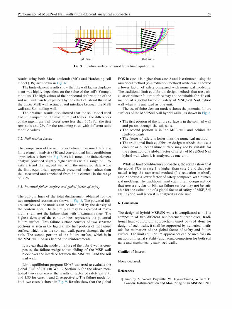
(a) Case 1 (b) Case 2
Fig. 9 Failure surface obtained from limit equilibrium.
Performance of MSE/Soil Nail walls using different analytical approaches 69
results using both Mohr coulomb (MC) and Hardening soilmodel (HS) are shown in Fig. 6 .
The finite element results show that the wall facing displace-
ment was highly dependent on the value of the soil’s Young’smodulus. The high values of the horizontal deformation of thesoil nail wall can be explained by the effect of lateral thrust ofthe upper MSE wall acting at soil interface between the MSE
wall and Soil nailing wall.The obtained results also showed that the soil model used
had little impact on the maximum nail forces. The differences
of the maximum nail forces were less than 10% for the firstrow nails and 2% for the remaining rows with different soilsmodulo values.
5.2. Nail tension forces
The comparison of the nail forces between measured data, the
finite element analysis (FE) and conventional limit equilibriumapproaches is shown in Fig. 7. As it is noted, the finite elementanalysis provided slightly higher results with a range of 10%with a trend that agreed well with the measured data while
the limit equilibrium approach presented higher values thanthat measured and concluded from finite element in the rangeof 30%.
5.3. Potential failure surface and global factor of safety
The contour lines of the total displacement obtained for the
two monitored sections are shown in Fig. 8. The potential fail-ure surfaces of the models can be identified by the density ofthe contour lines. The failure plan may be expected at maxi-
mum strain not the failure plan with maximum range. Thehighest density of the contour lines represents the potentialfailure surface. This failure surface consists of two separateportions as seen in the figures. The first portion of the failure
surface, which is in the soil nail wall, passes through the soilnails. The second portion of the failure surface, which is inthe MSE wall, passes behind the reinforcements.
It is clear that the mode of failure of the hybrid wall is com-
posite, the failure wedge shows sliding of the MSE wallblock over the interface between the MSE wall and the soilnail wall.
Limit equilibrium program SNAP was used to evaluate theglobal FOS of IH 410 Wall 7 Section A for the above men-
tioned two cases where the results of factor of safety are 2.71and 1.85 for cases 1 and 2, respectively. The failure mode forboth two cases is shown in Fig. 9. Results show that the global
FOS in case 1 is higher than case 2 and is estimated using thenumerical method (u–c reduction method) while case 2 showeda lower factor of safety compared with numerical modeling.
The traditional limit equilibrium design methods that use a cir-cular or bilinear failure surface may not be suitable for the esti-mation of a global factor of safety of MSE/Soil Nail hybridwall when it is analyzed as one unit.
The use of finite element models shows the potential failuresurfaces of the MSE/Soil Nail hybrid walls , as shown in Fig. 8.
� The first portion of the failure surface is in the soil nail walland passes through the soil nails.� The second portion is in the MSE wall and behind the
reinforcements.� The factor of safety is lower than the numerical method.� The traditional limit equilibrium design methods that use a
circular or bilinear failure surface may not be suitable forthe estimation of a global factor of safety of MSE/Soil Nailhybrid wall when it is analyzed as one unit.
While in limit equilibrium approaches, the results show thatthe global FOS in case 1 is higher than case 2 and that esti-mated using the numerical method (f–c reduction method),
case 2 showed a lower factor of safety compared with numer-ical modeling. The traditional limit equilibrium design methodthat uses a circular or bilinear failure surface may not be suit-
able for the estimation of a global factor of safety of MSE/SoilNail hybrid wall when it is analyzed as one unit.
6. Conclusion
The design of hybrid MSE/SN walls is complicated as it is acomposite of two different reinforcement techniques, tradi-
tional limit equilibrium approaches cannot be used alone fordesign of such walls, it shall be supported by numerical meth-ods for estimation of the global factor of safety and failuresurface. The limit equilibrium approaches can be used for esti-
mation of internal stability and facing connection for both soilnails and mechanically stabilized walls.
Conflict of interest
None declared.
References
[1] Timothy A. Wood, Priyantha W. Jayawickrama, William D.
Lawson, Instrumentation and Monitoring of an MSE/Soil Nail
70 M. Rabie
Hybrid Retaining Wall, Proceedings of the International
Foundation Congress and Equipment Expo. ASCE, 2009.
[2] R.J. Byrne, D. Cotton, J. Porterfield, C. Wolschlag, G.
Ueblacker, Manual for Design and Construction Monitoring
of Soil Nail Walls, Report FHWA-SA-96-69R, Federal
Highway Administration, Washington, 1998.
[3] C. Lazarte, V. Elias, D. Espinoza, Sabatini. Geotechnical
Engineering Circular No.7: Soil Nail Walls, Report No.
FHWA0-IF-017, Washington, 2003, p. 182.
[4] PLAXIS b.v. 2002. PLAXIS 2D – [software]. (Version 8, Finite
Element Code for Soil and Rock Analyses). P.O. Box 572, 2600
AN DELFT, Netherlands.
[5] K.B. Ebert, Validation and Verification of the Commercial
Finite Element Code PLAXIS for Non-Linear Geomechanics,
University of Colorado, Colorado, 1994, p. 229.
[6] S.A. Tan, W. Cheang, P. Ooi, D. Tan, Finite Element Analysis
of a Soil Nailed Slope-Some Recent Experience. 3rd Asian
Regional Conference on Geosynthetics: Now and Future of
Geosynthetics in Civil Engineering, 2004.
[7] K. Morrison, F. Harrison, J. Collin, A. Dodds, B. Arndt,
Shored Mechanically Stabilized Earth (SMSE) Wall Systems
Design Guidelines. Report No. FHWA-CFL/TD-06-001,
FHWA, Lakewood, CO, 2006.
[8] B.S. Yiqing wei, Development of equivalent surcharge loads for
the design of soil nailed segment of MSE/SOIL NAIL HYBRID
Retaining walls based on results from full-scale wall
instrumentation and finite element analysis, 2013.
[9] G.L.S. Babu, V. P. Vikas Pratap Singh, Simulation of Soil Nail
Structures Using PLAXIS 2D, PLAXIS Bulletin, Spring Issue,
2007, 16–21.
[10] D.M. Potts, L. Zdravkovic, Finite Element Analysis in
Geotechnical Engineering Application, first ed., Thomas
Telford Publishing, London, 2001.
[11] T.C. Sheahan, T. Oral, C.L. Ho, A Simplified Trial Wedge
Method for Soil Nailed Wall Analysis, J. Geotech. Geoenviron.
Eng. ASCE 129 (2) (2002) 117–124.
[12] CALTRANS, A User’s Manual for the SNAIL Program,
Version 5.01 – Updated PC Version, Sacramento, California,
1991.
[13] C. Shen, S. Bang, M. Herrman, Ground Movement Analysis of
Earth Support System, J. Geotech. Eng., ASC (1981) 1609–1624.
[14] I. Juran, Behaviour and Working Stress Design of Soil Nailed
Retaining Structures. Performance of Reinforced Soil
Structures, British Geotechnical Society, 1990, 207–217.
[15] Golder, GOLDNAIL Soil Nailing Design Program. Golder
Associates, Seattle, Washington, 1993.
[16] J.H. Long, W.F. Sieczkowski Jr., E. Chow, E.J. Cording,
Stability Analysis for Soil Nailed Walls. Geotechnical Special
Publication No. 25, American Society of Civil Engineers, New
York, 1990, 676–691.