performance of refrigerator operating with and
TRANSCRIPT
PERFORMANCE OF REFRIGERATOR OPERATING WITH AND WITHOUT
LIQUID-SUCTION HEATING
LOH WING LIONG
Report submitted in partial fulfillment of the requirements for the award of the degree
of Bachelor of Mechanical Engineering
Faculty of Mechanical Engineering
UNIVERSITI MALAYSIA PAHANG
JUNE 2012
vii
ABSTRACT
A modern refrigeration system consists of four main components which is a
compressor, a condenser, an evaporator and a throttling device. There are many
researches which have been conducted in order to achieve good performance of the
refrigeration system such as two stage refrigeration system, energy systems and suction
heating. Suction heating is based on the concept of heat transfer between the capillary
tube and suction tube. Suction heating is applied in order to absorb heat and thus
lowering the temperature if the refrigerant at the capillary tube. The main purpose of
this project is to investigate the performance of refrigeration operating with and without
liquid suction heating in order to investigate how much the suction heating influence the
performance of the refrigeration system. The project is based on experimental study on
refrigeration system test rig and two setup of experimental studies which is the
experimental setup for refrigeration operating with suction heating and experimental
setup for refrigeration operating without suction heating. Both sets of system
configuration will be run until it reaches steady operating condition before data is
collected in order to calculate the coefficient of performance (COP). Results show that
the refrigeration system operating with liquid suction heating has the highest value of
COP which is 2.14 compare with the system operating without suction heating which is
1.8. The percentage difference in COP is about 15.89 percent.

viii
ABSTRAK
Sistem penyejukan moden terdiri daripada empat komponen utama iaitu pemampat,
pemeluwap, penyejat dan tiub kapilari. Terdapat banyak penyelidikan yang telah
dijalankan untuk mencapai prestasi baik sistem penyejukan seperti dua peringkat sistem
penyejukan, sistem tenaga dan pemanasan sedutan. Pemanasan sedutan adalah
berdasarkan konsep pemindahan haba antara tiub kapilari dan tiub sedutan. Pemanasan
sedutan digunakan untuk menyerap haba dan seterusnya mengurangkan suhu jika
penyejuk di tiub rerambu Tujuan utama projek ini dijalankan adalah untuk mengenal
pasti prestasi antara sistem peti sejuk yang beroperasi dengan kaedah pemindahan haba
dan sistem yang tidak beroperasi dengan pemindahan haba untuk menyiasat berapa
banyak pemanasan sedutan mempengaruhi prestasi sistem penyejukan. Projek ini adalah
berdasarkan kajian eksperimen pelantar ujian sistem penyejukan dan dua persediaan
kajian eksperimen yang setup eksperimen bagi operasi penyejukan dengan pemanasan
sedutan dan persediaan eksperimen bagi penyejukan beroperasi tanpa pemanasan
sedutan. Kedua-dua set konfigurasi sistem akan berjalan sehingga ia mencapai keadaan
operasi yang tetap sebelum data dikumpul untuk mengira pekali prestasi (COP). Hasil
kajian menunjukkan bahawa sistem penyejukan yang beroperasi dengan pemanasan
sedutan cecair mempunyai nilai tertinggi COP yang adalah 2.14 berbanding dengan
sistem operasi tanpa pemanasan sedutan yang ialah 1.8. Perbezaan peratusan dalam
COP adalah kira-kira 15.89 peratus.

ix
TABLE OF CONTENTS
Page
EXAMINER’S APPROVAL ii
SUPERVISOR’S DECLARATION iii
STUDENT’S DECLARATION iv
DEDICATION v
ACKNOWLEDGEMENTS vi
ABSTRACT vii
ABSTRAK viii
TABLE OF CONTENTS ix
LIST OF FIGURES xii
LIST O TABLES xiv
LIST OF ABBREVIATIONS xv
LIST OF SYMBOLS xvi
CHAPTER 1 INTRODUCTION
1.1 Project Background 1
1.2 Problem Statement 3
1.3 Objectives 3
1.4 Scopes 3
CHAPTER 2 LITERATURE REVIEW
2.1 Introduction 5
2.2 Thermodynamics Law and Refrigeration System 6
2.3 Vapor compression refrigeration cycle 7
2.3.1 Carnot Refrigeration Cycle 7
2.3.2 Ideal Vapor Compression Refrigeration Cycle 9
2.3.3 Actual Vapor Compression Refrigeration Cycle 13

x
2.4 Main components of refrigeration system 14
2.4.1 Throttling device 14
2.4.2 Compressor 17
2.4.3 Condenser 19
2.4.4 Evaporators 21
2.5 Journal Synthesis 22
2.5.1 Numerical studies on capillary tube-suction line heat
exchanger 22
2.5.2 A design model for capillary tube-suction line heat
exchangers 26
2.6 Refrigerants 31
CHAPTER 3 METHODOLOGY
3.1 Introduction 34
3.2 Methodology Flow Chart 35
3.3 Experimental Setup of Test Rig 37
3.4 Equipment and materials 38
3.4.1 Thermocouple 38
3.4.2 Bourdon tube pressure gauge 38
3.4.3 Mini bar refrigerator 39
3.5 Tools 40
3.6 Experimental Test Setup 40
3.6.1 Experimental setup for with suction heating 40
3.6.2 Experimental setup for without suction heating 44
CHAPTER 4 RESULTS AND DISCUSSION
4.1 Introduction 47
4.2 Data collection 48
4.2.1 Refrigeration operating with suction heating 48
4.2.2 Refrigeration operating without suction heating 50
4.3 Enthalpy value determination 51
4.4 Determination of coefficient of performance (COP) 52

xi
4.5 Data Analysis 54
4.5.1 The temperature gradient at suction line 54
4.5.2 Graph of COP 54
4.5.3 Percentage Differences 55
4.6 Discussion 56
CHAPTER 5 CONCLUSION AND RECOMMENDATIONS
5.1 Conclusion 58
5.2 Recommendations 59
REFERENCES 60
APPENDICES
A hp Diagram for Suction Heating 62
B hp Diagram for Without Suction Heating 63
C Gantt Chart PSM 1 64
D Gantt Chart PSM 2 65
xii
LIST OF FIGURES
Figure No. Title Page
2.1 Reversed Carnot Cycle 8
2.2 Ideal vapor compression refrigeration cycle (a) T-s diagram, (b) P-h
diagram
10
2.3 Schematic diagram of the vapor compression refrigeration cycle 12
2.4 The actual vapor compression refrigeration cycle (a) schematic
diagram of vapor compression cycle, (b) T-s diagram of actual
vapor compression refrigeration cycle
14
2.5 Expansion process of liquid refrigerant 17
2.6 Cut-in view of the hermetic compressors 19
2.7 Graph of heat transfer rate (W) versus the condensing temperature
(K)
24
2.8 Graph of heat transfer rate (W) versus evaporating temperature (K)
25
2.9 Graph of heat transfer rate (W) versus the internal diameter of the
capillary tube (mm)
26
2.10 Vapor compression cycle with capillary tube- suction line heat
exchanger
28
2.11 The configuration between capillary tube and suction line
28
2.12 Schematics diagram of typical vapor-compression refrigeration
system with liquid-suction heat exchanger
29
2.13 Schematic diagram of capillary-tube suction line heat exchanger 31
3.1 Methodology flow chart
36
3.2 Thermocouple 38
3.3 Bourdon tube pressure gauge 39
3.4 UPSON mini bar refrigerator 39
3.5 Coiling of capillary tube to suction tube to form liquid suction
heating
42

xiii
3.6 Schematic diagram of refrigeration system with suction heating 43
3.7 Isolation of capillary tube from suction tube 45
3.8 Schematic diagram of refrigeration system without suction heating 46
4.1 Graph of COP versus days of experiments 55

xiv
LIST OF TABLES
Table No. Title Page
3.1 Specification of mini bar refrigerator as system test rig
37
4.1 Data for refrigeration system operating with suction heating 48
4.2 Data for refrigeration system operating without suction heating 50
4.3 Enthalpy value for refrigeration system with and without
suction heating
51
4.4 Calculated value of the refrigeration system 53
4.5 Temperature gradient at suction line 54
4.6 The percentage of difference for two different operating system 56

xv
LIST OF ABBREVIATIONS
COP Coefficient of Performance
ASHRAE American Society of Heating, Refrigeration and Air-Conditioning
Engineer

xvi
LIST OF SYMBOLS
QL Cooling load
QH Heat rejected
Win Compressor work
T-s Temperature – entropy
p-h Pressure - enthalpy

CHAPTER 1
INTRODUCTION
1.1 PROJECT BACKGROUND
The refrigeration system cycle is based on the working principle of the vapor-
compression refrigeration cycle which is modified from the reversed Carnot cycle. The
continuous improvement and modifications of the reversed Carnot cycle have resulted
in the introduction of the vapor-compression refrigeration cycle and until now, the
household refrigeration and air conditioning working principle is based on this cycle.
From the time Jacob Perkins an Englishman, built a prototype of closed cycle ice
machine based on the vapor compression cycle in 1834 and were commercialized by
Alex Twinning in 1850, continuous research and experiments have been done to
enhance the performance of the refrigerator based on higher efficiency and cost saving.
A basic refrigeration system consists of four important component and devices
which is the compressor, condenser, evaporator and an expansion valve. Based on the
vapor compression refrigeration cycle, these four components and devices will
influence the efficiency of the refrigeration system which is measured by its coefficient
of performance (COP). The effectiveness of each components and devices working
functionality will directly influence the performance of the whole refrigeration system.
The influence of these four components have on the performance of the whole
refrigeration system is very conclusive that most research and studies to improve the
performance of the refrigeration system is mostly based on these four components.
The rate and amount at which the condenser discharges the heat to the
environment and also the rate and amount which the evaporator absorbs heat from the

2
compartment can be a measure of performance and efficiency of the refrigeration
system. However, the expansion device is also an important device that is currently
under extensive research and studies as to increase the performance of the refrigeration
system based on reheating process. The expansion device can be either a expansion
valve or capillary tube which is used to expand the refrigerant to low temperature and
pressure before entering evaporator. From the model of the research done by Klein
(2000) using liquid-suction heat exchanger, high temperature refrigerant from the
condenser was sub cooled prior to entering the throttling device using the low
temperature refrigerant from the evaporator as the heat sink.
Basic model of capillary tube-liquid suction tube heat exchanger is built to
model the function of heat exchanger due to its simplicity and also it’s significant in the
performance study of the refrigeration system. In this model, the liquid suction tube will
be wounded outside along the capillary tube which is connecting the condenser and
evaporator. By doing so, the heat exchange between the capillary tube and liquid
suction tube will be more direct and thus reducing the heat loss effect to the surrounding
air. The different of length of liquid suction tube wounded along the capillary tube will
influence the heat exchange and thus a optimum length will be determined. The
performance studies of the refrigeration will also be done to compare between the
coefficient of performance (COP) of the refrigeration system with and without liquid
suction heating.
Several unaffected parameters which will not influenced the performance studies
of the refrigeration will be considered constant such as the refrigerant mass flow rate,
heat loss to surrounding, type of refrigerant (R-134a) and also the heat transfer in the
evaporator and condenser is constant. Nevertheless, these parameters will indirectly
affect the coefficient of performance of the refrigeration system, however, since the
effect is minimal and will not influence with the studies, they are conceded constant.
In this project, the refrigeration system will be operated with and without liquid
suction heating. Literature on the fundamental calculations and important points of
interest in determination of the performance of the refrigeration system is done in order
to obtain the frame of reference besides the studies from other researchers. The contents
3
will prove the contribution of suction heating to refrigeration performance and also the
affordability to remove suction heating by using secondary source heat for heating the
refrigerant before undergoing compression work. The parameter used to measure the
performance of the refrigeration system is coefficient of performance (COP).
1.2 PROBLEM STATEMENT
The performance study of refrigeration system is a topic of interest whereby lots
of studies and research have been done in order to improve the performance of the
refrigeration system by reducing the workload particularly the compressor work and
capillary tube. Thus, by identifying and modifying the parameters of interest which is
the liquid suction heat exchanger operating at the throttling device that connects
between condenser and evaporator together, a study of performance of refrigeration
operating with and without liquid suction heating could be done using the coefficient of
performance (COP) as a measured of performance for the suction heating. Nevertheless,
suction heating would require additional time and cost to either brazing the suction tube
with the capillary tube or winding up the suction tube around the capillary tube. Since
the main purpose of suction heating is to increase the refrigerant temperature at the
compressor suction line, it have been suggested that utilizing the motor heat from the
hermetic metal casing of the compressor is sufficient enough to ensure the refrigerant is
fully vaporize before entering the compressor thus reducing the work load of the
compressor.
1.3 OBJECTIVES
The main objective on this project is to investigate and analyze performance of
the refrigerator operating with and without the liquid suction heating.
1.4 SCOPES
i. Literature and fundamental study on refrigeration system and effect of suction
heating
4
The literature research and review mainly focused on understanding of basic
refrigeration cycle and the components of the refrigeration system. Besides,
the literature is also widened to include to on the study of suction heating and
its effect on the performance study of the refrigeration system. The important
parameter needed as a measure of efficiency and performance of refrigeration
system such as the refrigerant load, compressor work and the coefficient of
performance.
ii. Fabrication of experimental rig for with suction heating
The fabrication of suction heating is done by coiling the suction tube around
the capillary tube to allowed heat exchange to occur between the capillary tube
and the suction tube of the compressor. The setting up of the experiment is done
by isolating between the suction tube and capillary tube to produce experiment
without suction heating and then brazing or coiling of suction tube with capillary
tube to conduct experiment with suction heating.
iii. Conducting experiment of refrigeration system with and without suction heating
The experiment of the project on the refrigeration system will be conducted
based on two parameters, which is with suction heating and without suction
heating. The measure of performance for the parameter is based on the
calculation of COP. The higher the COP, the better the performance of the
refrigeration system.
iv. Analysis of the data collected
Based on the collected data for both experiment with and without suction
heating, a detailed calculation is done and the important parameters needed to
get the coefficient of performance (COP) is calculated. From the analysis, the
COP value and graph will be obtained and analyze.

CHAPTER 2
LITERATURE REVIEW
2.1 INTRODUCTION
In a literature review, the basic operation functions of refrigeration system will
be discussed in detail so that a clear overview of refrigeration system is obtained.
Besides, the suction heating in refrigeration system will also be analyzed and discussed
in this chapter in order to understand the function of suction heating and its contribution
to the performance and efficiency of the refrigeration system. The cycle encompassed
by this refrigeration system which is the ideal vapor compression refrigeration system
will also be fully utilized and discussed in this chapter. The ideal vapor compression
refrigeration system is very important in this study as it shows the important points to
measure the temperature and pressure of the refrigeration system. The literature review
will also include the study of the devices involved in operating the refrigeration system.
The basic functions of each device will be discussed and the contributions and
importance of each device in the system will be briefly explained. Nevertheless, the
frame of reference for the measurement of the performance of the refrigeration system
will be established for the study done by researcher and also doing preliminary
experimental study of the operating refrigeration system. The important parameter
involves in determining the performance of refrigeration system will be included in this
literature review and so is the theoretical and the formula needed for calculation.
6
2.2 THERMODYNAMICS LAW AND REFRIGERATION SYSTEM
In order to understand the basic function of refrigeration system, there are two
important thermodynamics law that needs to be understood. The first law is the First
Law of Thermodynamics. The First Law of Thermodynamics states that energy is a
thermodynamics property. The First Law also states that energy cannot be created nor
destroyed but rather change from one form to another form of energy (Cengel, 2007).
Mainly, the statement from the First Law of Thermodynamics intends to focus on the
conservation of energy. However, a process which satisfies the First law of
Thermodynamics does not necessarily mean the process will take place unless it
satisfies the Second Law of Thermodynamics. The Second Law of Thermodynamics
states that energy actually has quality as well as quantity and the processes occur in the
direction of decreasing quality energy (Cengel, 2007). This goes to show that heat, a
type of energy, and flows from a hotter environment to the colder environment.
Nevertheless, German physicist and mathematician, Rudolf Julius Emanuel
Clausius, with his statements “It is impossible to construct a device that operates in a
cycle and produces no effect other than the transfer of heat from a lower temperature
body to a higher temperature body” (Cengel, 2007), have shed light on the operation of
refrigeration systems without violating the Second Law of Thermodynamics. The
statement generally implies that, for cyclic devices such as refrigerator to transfer heat
from colder to hotter space, an external power source is needed to be consumed
whereby it could be said that the compressor is driven by an external power source
(Cengel, 2007). The amount of power consumed to operate the compressor will be
considered to calculate the performance and efficiency of the refrigeration system in the
latter stage.

7
2.3 VAPOR COMPRESSION REFRIGERATION CYCLE
2.3.1 Carnot Refrigeration Cycle
The Carnot cycle is a totally reversible cycle which consists of two reversible
isothermal and two isentropic processes. Carnot cycle serves as the standard against any
actual power cycles due to its maximum thermal efficiency. All the four processes are
reversible and by reversing the cycles, the directions of the heat and work interactions
also been reversed. The resulting reversed Carnot cycle is also called the Carnot
refrigerator or the Carnot heat pump as shown in Figure 2.1(a). The process flow that
occurs if the reversed Carnot cycle is executed within the saturation dome of a
refrigerant as shown from Figure 2.1(b) can be considered as the most efficient
refrigeration cycle operating between two specified temperature levels. In process 1-2
the refrigerant will absorbs heat isothermally from a low temperature source at TL in the
amount of QL. The refrigerant is then isentropically compressed to state 3 where the
temperature will rises to TH from process 2-3. From process 3-4, the heat at temperature,
TH, is then rejected isothermally to high temperature sink in the amount of QH. During
the course of the process 3-4 also, the refrigerant changes from saturated vapor state to
saturated liquid state which occur in the condenser. After rejecting the heat isothermally,
the refrigerant is then expanded isentropically to state 1 and the temperature of the
refrigerant also drops to TL.
The heat absorbed, QL = h2 – h1
(2.1)
The heat rejected, QH = h3 – h4
(2.2)
The compressor work, Win = h3 – h2
(2.3)
The COP for refrigerator is also expressed as
COP =
(2.4)

8
As the difference between both the temperatures decreases, the COP also increases
which is either TH falls or TL rises.
These cycles however cannot be a suitable model in practice using the
refrigerator devices. The process from 2 to 3 and also 4 to 1 could not be achieved as it
will require the compressor to handle two phases of mixture at one which is
unachievable and also the turbine to expand the high moisture content refrigerant in a
turbine. It is highly impossible for compressor to handle two phases of the refrigerant at
the same time and also expansion of high moisture content in turbine will cause the
turbine to cavitate as results of corrosion. Therefore, the reversed Carnot cycle could
only be used as a standard against which actual refrigeration cycles are compared
(Cengel, 2007).
(a) (b)
Figure 2.1: Reversed Carnot Cycle (a) Carnot heat pump diagram (b) T-s diagram
Source: Cengel (2007)

9
2.3.2 Ideal Vapor Compression Refrigeration Cycle
The ideal vapor compression refrigeration cycle is the modifications from the
reversed Carnot cycle and is the most suitable and ideal representation of the
refrigeration cycles. In ideal refrigeration cycle, the process refrigerant before entering
compressor was vaporized completely and the expansion valve was used to replace the
turbine to create a low quality mixture of refrigerant. Although it does not clearly depict
the actual vapor compression refrigeration cycle, however it is the most idealistic
representation of the refrigeration cycle. In this cycle, the devices use is the condenser,
evaporator, expansion valve and compressor. In this cycle, the refrigerant will be
vaporized completely in the evaporator before entering the compressor to ensure that the
compressor is only handling one phase of refrigerant which is saturated vapor. While to
expand the refrigerant at the state of saturated liquid, an expansion valve is used to
replace the turbine and producing a low quality mixture of liquid and vapor at a very
low temperature and pressure before entering the evaporator.
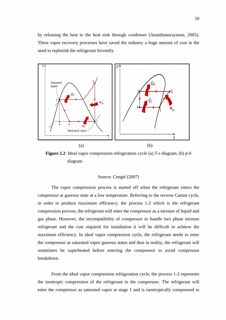
Figure 2.2 is the ideal vapor compression refrigeration cycle diagram whereby,
Figure 2.2(a) is the temperature-entropy (T-s) diagram of the cycle and Figure 2.2(b) is
the pressure-enthalpy (p-h) diagram of the cycle. Both of the diagrams show the ideal
flow process of the refrigerant inside the refrigeration system. There are a total of four
stages of operation that the refrigerant has to go through inside the refrigeration system
and each stage is accomplished by a device that will process the refrigerant entering the
devices. Thus, the refrigeration system is made up of four main devices which are the
compressor, evaporator, condenser and throttling device (Ananthanarayanan, 2005).
The ideal vapor compression refrigeration cycle is the simplest most basic cycle
used by most refrigeration systems and also air conditioning system to represent the
process flow of the cycle. Since its introduction to the world by Jacob Perkins, effort
has been made to idealize the vapor compression refrigeration cycle in order to obtain
the highest efficiency and performance can be produced by the system. From the name
itself, vapor compression refrigeration system, it can be explained that the vapor
refrigerant will be compressed to superheated state and being recovered to liquid state
10
by releasing the heat to the heat sink through condenser (Ananthanarayanan, 2005).
These vapor recovery processes have saved the industry a huge amount of cost in the
need to replenish the refrigerant fervently.
(a) (b)
Figure 2.2: Ideal vapor compression refrigeration cycle (a) T-s diagram, (b) p-h
diagram
Source: Cengel (2007)
The vapor compression process is started off when the refrigerant enters the
compressor at gaseous state at a low temperature. Referring to the reverse Carnot cycle,
in order to produce maximum efficiency, the process 1-2 which is the refrigerant
compression process, the refrigerant will enter the compressor as a mixture of liquid and
gas phase. However, the incompatibility of compressor to handle two phase mixture
refrigerant and the cost required for installation it will be difficult to achieve the
maximum efficiency. In ideal vapor compression cycle, the refrigerant needs to enter
the compressor as saturated vapor gaseous states and thus in reality, the refrigerant will
sometimes be superheated before entering the compressor to avoid compressor
breakdown.
From the ideal vapor compression refrigeration cycle, the process 1-2 represents
the isentropic compression of the refrigerant in the compressor. The refrigerant will
enter the compressor as saturated vapor at stage 1 and is isentropically compressed to
11
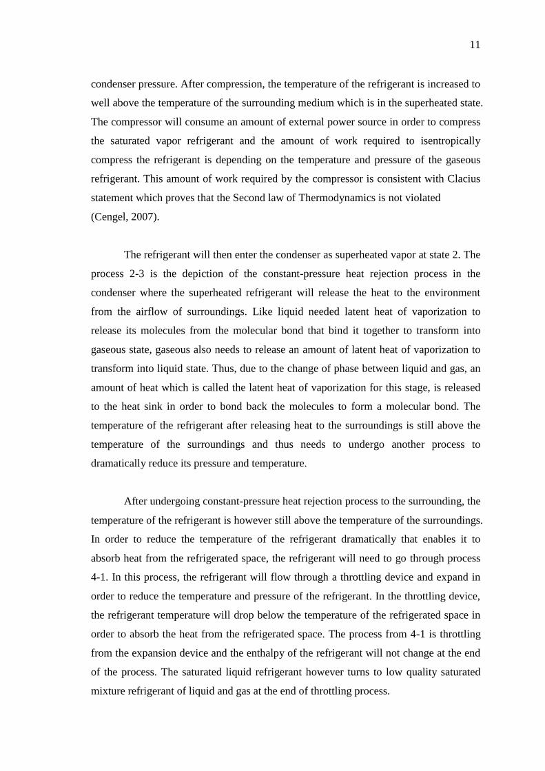
condenser pressure. After compression, the temperature of the refrigerant is increased to
well above the temperature of the surrounding medium which is in the superheated state.
The compressor will consume an amount of external power source in order to compress
the saturated vapor refrigerant and the amount of work required to isentropically
compress the refrigerant is depending on the temperature and pressure of the gaseous
refrigerant. This amount of work required by the compressor is consistent with Clacius
statement which proves that the Second law of Thermodynamics is not violated
(Cengel, 2007).
The refrigerant will then enter the condenser as superheated vapor at state 2. The
process 2-3 is the depiction of the constant-pressure heat rejection process in the
condenser where the superheated refrigerant will release the heat to the environment
from the airflow of surroundings. Like liquid needed latent heat of vaporization to
release its molecules from the molecular bond that bind it together to transform into
gaseous state, gaseous also needs to release an amount of latent heat of vaporization to
transform into liquid state. Thus, due to the change of phase between liquid and gas, an
amount of heat which is called the latent heat of vaporization for this stage, is released
to the heat sink in order to bond back the molecules to form a molecular bond. The
temperature of the refrigerant after releasing heat to the surroundings is still above the
temperature of the surroundings and thus needs to undergo another process to
dramatically reduce its pressure and temperature.
After undergoing constant-pressure heat rejection process to the surrounding, the
temperature of the refrigerant is however still above the temperature of the surroundings.
In order to reduce the temperature of the refrigerant dramatically that enables it to
absorb heat from the refrigerated space, the refrigerant will need to go through process
4-1. In this process, the refrigerant will flow through a throttling device and expand in
order to reduce the temperature and pressure of the refrigerant. In the throttling device,
the refrigerant temperature will drop below the temperature of the refrigerated space in
order to absorb the heat from the refrigerated space. The process from 4-1 is throttling
from the expansion device and the enthalpy of the refrigerant will not change at the end
of the process. The saturated liquid refrigerant however turns to low quality saturated
mixture refrigerant of liquid and gas at the end of throttling process.
12
Lastly, the low quality saturated mixture refrigerant will enter the evaporator at a
very low pressure and temperature. The process 4-1 is the constant-pressure heat
absorption process in the evaporator. The refrigerant mixture will enter the evaporator
and completely evaporates by absorbing the heat from the refrigerated space. The
refrigerant will then leave the evaporator as saturated vapor and reenters the compressor
to complete the cycle. The cycle will continue and the refrigerated space will continue
to be cooled by the refrigerant which undergoes the process continuously.
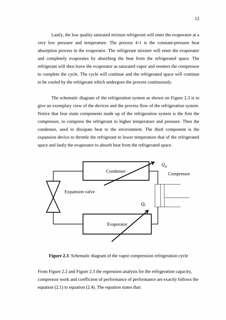
The schematic diagram of the refrigeration system as shown on Figure 2.3 is to
give an exemplary view of the devices and the process flow of the refrigeration system.
Notice that four main components made up of the refrigeration system is the first the
compressor, to compress the refrigerant to higher temperature and pressure. Then the
condenser, used to dissipate heat to the environment. The third component is the
expansion device to throttle the refrigerant to lower temperature that of the refrigerated
space and lastly the evaporator to absorb heat from the refrigerated space.
Figure 2.3: Schematic diagram of the vapor compression refrigeration cycle
From Figure 2.2 and Figure 2.3 the regression analysis for the refrigeration capacity,
compressor work and coefficient of performance of performance are exactly follows the
equation (2.1) to equation (2.4). The equation states that:
Condenser
Evaporator
Compressor
Expansion valve
QL
QH

13
The cooling load, QL,
QL = h1 – h4
The compressor work input required,
Win = h2 – h1
Thus, the coefficient of the performance of the refrigerant (COP),
COP =
2.3.3 Actual Vapor Compression Refrigeration Cycle
The actual vapor compression cycle is the actual representation of refrigerant
behaviour during the cycle flows. In this cycle, several irreversibility was taken into
consideration such as fluid frictions and also heat transfer to or from the surroundings.
When the refrigerant about to enters the compressor, it is slightly superheated to enable
it to completely vaporized. During the transfer of refrigerant from evaporator to
compressor, the friction effect will also cause pressure drop and also heat transfer to
surroundings to gain (Ananthanarayanan, 2005). Thus, superheating the refrigerant
before entering the compressor will compensate for the pressure drop and heat loss. The
effect of friction force during the transfer of refrigerant from compressor to condenser
will cause the increase and decrease of entropy an also heat transfer. Thus, cooling the
refrigerant to the state 2’ is desirable. After flowing from condenser, the refrigerant are
not precisely in the state of saturated liquid as it is hard to control the behavior of the
refrigerant. Thus, the refrigerant will be sub cooled to ensure it is completely condensed
before entering throttling valve.