periodic lubrication and attention - rroc
TRANSCRIPT

PERIODIC LUBRICATION AND ATTENTION. 13
CHAPTER II
Periodic Lubrication and AttentionLUBRICANTS RECOMMENDED
Rolls-Royce Limited recommend a first quality oil of viscosity S.A.E. 30 for the engine and gearbox all year round. NOTE.- The recommended oil for use in the engine may require slight modification if the engine is in very poor condition, in which case use of an S.A.E. 40 viscosity oil may be to advantage. Any of the following oils are suitable:- “A” “B” “C” Engine. Gearbox Hand-oiling S.A.E. 30. S.A.E. 40. Points.Price’s Energol ... 30 40 30 20Wakefield’s Castrol ... X.L. X.X.L. X.L. CastroliteShell ... ... ... X. 100 X.100 X. 100 X. 100 S.A.E. 30 S.A.E. 50 S.A.E. 30 S.A.E. 20Duckham’s Adcoidised NP NP NP NP “Thirty” “Fifty” “Thirty” “Twenty”Essolube ... ... 30 40 30 20Gulf Oil (Great Britain) Speedolene Speedolene Speedolene Speedolene Ltd. T B T 20 In the instructions which follow, reference is made to Oil “A”, “B” or “C”.Rear Axle. Wakefield’s Special Castrol Hi-press S.C. (No other oil is recom-mended, but in extreme circumstances, if this is unobtainable, use a first quality hypoid oil. Do not mix.)Steering Box, Chassis Oil Pump and Starter Motor Gears. Viscosity 30 as under “A” above.Hydraulic Shock Dampers. As under “C” above Do not mix.Front and Rear Hubs. Belmoline C, Retinax R.B., or similar type of ball-bearing grease.Propeller Shaft, Contact Breaker Cam and Wheel Hub Shells. Retinax C.D., Mobilgrease No. 2, or a similar type of grease.

Front Spring Shackle (ZS.2)Front Brake OperatingShaft (innerbearing) (ZT.1)Front Brake Camshaft(S.1)Front Brake OperatingShaft (outerbearing) (S.0)
Supply to Front Axle
Foot Operated Oil Pumpfor Chassis System
Fulcrum and Countershaft ofT-shaped Balancing Lever (ZT.0)
Cylinder of ServoDamper (ZE.0)Foot Brake Equaliser(ZS.0)Hand Brake EqualiserShaft (ZE.00)
Supply to Rear Axle
Rear Brake LeverShaft (ZS.1)
Rear Brake CamshaftsFoot Brake (TS.3)Hand Brake (ZT.3)
Front Axle Control(ZT.3) and Shock
Damper Connec-tions (ZE.3)
Front Ball Joint of SideSteering Tube
(Supplied Direct)Upper Pivot Bearing
(S.2)Ball Joints of Cross
Steering Tube(Supplied Direct)
Front Spring Pin and Spring Leaves(ZS.1)
Steering Lever Shaftand Ball Joint (ZE.1)Clutch Thrust Race
(ZT.00)Pedal Shaft (ZT.0)
Front Brake Equaliserand Shaft (ZS.2)
Clutch Withdrawal Shaft (ZT.2
Hand Brake LeverFulcrum (ZT.0)
Foot Brake EqualiserShaft (ZT.00)
Hand Brake Equaliser(ZE.00
Rear Spring Pinand Spring Leaves
(ZS.2)
Rear BrakeIntermediate Levers
(ZE.0)
Rear Shock DampersConnections
(Supplied Direct)
Rear Spring Shackle(ZS.3)
Fig. 3.- DIAGRAM OF CHASSIS LUBRICATION SYSTEMR 25/30 NO XVIIR
PERIODIC LUBRICATION AND ATTENTION. 15
Distributor Lubricator As under “C”Water Pump Belmoline A, Retinax P, or a similar type of grease.
CAPACITIES Engine ... ... ... ... ... ... I¼ gallons Gearbox ... ... ... ... ... 5 pints Rear Axle ... ... ... ... ... 2 pints Cooling System ... ... ... ... ... 3¾ gallons Fuel Tank ... ... ... ... ... 18 gallons Chassis Oil Pump ... ... ... ... 2 pints
CENTRALISED CHASSIS LUBRICATION SYSTEMGeneral A foot-operated pump,with which is combined an oil reservoir, is located on the front of the dashboard, and supplies oil under pressure for chassis lubrication. A diagram of the complete system is given in Fig. 3, the piping being coloured red. . Red discs indicate the position of drip plugs, and the rating of each is given in parentheses against the description of the part lubricated.Foot-operated Oil Pump. The chassis oil pump is shown in Fig 4. Normally no attention to the system is necessary beyond filling of the reservoir with engine oil after removal of the filler cover, A. This should be done every 2,500 miles, as directed on page 20. It should not be filled above I inch from the top of the filler cover. When the reservoir is nearly empty it will be found that the pedal returns instantly after depression, due to the presence of air in the system. On the other hand, if the pedal takes an abnormal length of time to return to its raised position, this may indicate that the felt strainer located at the botom of the reservoir is choked. Under these circum-stances a new felt strainer must be fitted. This is arranged at the bottom of the reservoir and is removed by disconnecting the two unions, B, and unscrewing the cap, C. An aluminium distance washer, the felt strainer pad, and a wire gauze support can the be taken out. When replacing the parts, the wire gauze support should be re-fitted in the cap first, followed by a new felt pad, and, finally, the aliminium distance washer with its recessed face towards the felt pad. Packing washers are provided on either side of the aluminium washer and it should be observed that these are in position.

16 ROLLS-ROYCE 25-30 H.P. CAR Normally, the felt strainer pad should be discarded and a new one fitted every 20,000 miles, as directed on page 24. It should never be necessary further to dismantle the pump.
Drip Plugs. The drip plugs are non-adjustable and non-demountable, and are lettered and numbered to indicate their shapes and relative rates of oil emission respectively, a higher number indicating a greater rate. The drip plugs never require cleaning, and, being non-demountable no attempt must be made to take them apart. If one is suspected of being defective, it should be replaced with a new plug of the same rating.Front Axle System. The arrangement of the front axle system renders it necessary to provide separate strainers. For convenience these are located on the ends of the axle, as shown in G, Fig. 5, which also shows the component parts inset.
Fig. 4. - FOOT-OPERATED CHASSIS OIL PUMP
The felt strainers should be renewed every 20,000 miles, as directed on page 24, the procedure being as follows:-
PERIODIC LUBRICATION AND ATTENTION. 17
Fig. 5. - STRAINERS ON FRONT AXLE
I. Carefully clean the outsides of the fittings with a brush and paraffin to prevent the ingress of dirt during dismantling.2. Unscrew the outer plug, G, with a box spanner.3. Unscrew the inner plug , J, with a box spanner. This plug carries the felt strainer, K, which should be removed and discarded.
All parts should be carefully cleaned and freed of every trace of grit before replacing. The perforated backing washer, L, must be replaced in the inner plug, J, before fitting the new felt strainer, K, with its gauze-covered side towards the washer. Two aluminium packing washers are provided, one, JI, between the inner plug, J, and the bottom of the recess in the axle, and the other, GI, under the shoulder of the outer plug, G. Care must be taken to replace these.

OIL P
RESS
URE
GAUG
E
OIL
STR
AINE
RDR
AIN
PLUG
OIL
LEVE
L (1¼
GAL
LONS
)
OIL
RET
URN
PUSH
RO
DS
CAM
SHAF
T
OIL D
ISTR
IBUT
ING
MAIN
PRES
SURE
GAU
GE O
NIN
STRU
NEMT
BOA
RD
DELIV
ERY
PIPE
SUCT
ION
PIPE
Fig.
6. -
ENG
INE
LUBR
ICAT
ION
SYST
EM
OVER
FLOW
FRO
M RE
LIEF
VALV
E
RELIE
F VA
LVE
DRAI
N PL
UG
OIL P
UMP
SUPP
Y TO
ROC
KER
SHAF
T
HOLL
OW R
OCKE
R SH
AFT FR
ONT
END
ELE
VATI
ON
OIL R
ETUR
N
PUSH
RO
DSSU
PPLY
TO D
YNAM
ODR
IVE
GEAR
OIL
FIL
LER
OIL D
ISTR
IBUT
ING
MAIN
OIL L
EVEL
INDI
CATO
R
MAIN
BEA
RING
CO
NNEC
TION
OIL J
ET TO
TIMI
NG
GEAR
PERIODIC LUBRICATION AND ATTENTION. 19
Points of Regular Attention according to use of Car
DAILY.Engine Oil.
When engine is not running, inspect level indicator on left side of crankcase and maintain quantity of oil at one-and-a-quarter gallons. If necessary, add oil through filler by means of a strainer funnel. Do not run engine with indicator showing less than three-quarters of a gallon.Radiator. Inspect coolant level and maintain half-way up return pipe. (See L, Fig.21.)Chassis Lubrication. Depress oil pump pedal once while engine is being started for first time in the day, and subsequently once every 100 miles. (If car is to be driven only a few miles, half a pumpful will be sufficient at first starting.)
EVERY 2,500 MILESDynamo Bearings Inject two or three drops only of oil “C” with the oil can into each lubricator.Battery Ignition Governor. Inject a few drops of oil “c” with the oil can into spring-lid lubricator.Cam of Battery Ignition Contact Breaker. Smear a trace only of grease on cam surface.Water Pump Bearing and Gland. Remove lubricator cap, fill one-third full of recommended grease and screw right down, preferably when engine is warm.Steering Box. Remove plug and fill with oil “A” to mouth of plug orifice.

20 ROLLS-ROYCE 25-30 H.P. CAR
Chassis Lubrication. Inspect oil level in reservoir and add more oil “A” if necessary.Only fill to one inch from top of filler cover.Valve Rocker Clearances. Check and reset if necessary. These should be .006” for both the inlet and exhaust, when engine is cold.
Fig. 7.- ADJUSTING THE VALVE ROCKER CLEARANCES. The method of adjusting the valve rocker clearances is illustrated in Fig. 7. The ball ended contact screw, V, is screwed into the rocker and locked bu a nut, U. On releasing the nut the screw can be turned by means of the special spanner provided. A feeler gauge is provided in the tool kit, and is shown in position at W for measuring the clearance. The exhaust rockers are marked EX. Before commencing to adjust a valve rocker, it should be ascertained that that particular tappet roller is well away from the cam, which is best done by turning the crankshaft by hand until the valve has opened and closed, and then cranking round half a revolution beyond this point.
PERIODIC LUBRICATION AND ATTENTION. 21
As each contact screw is adjusted, its locknut should be securely tightened up.Fan. Tension on the belt should be such that one side, at a point equi-distant from the pulleys, may be moved transversely with the fingers through about ¾”. Check and adjust if necessary. (See Fig. 22.)Brakes. Adjust if necessary. (See page 40.)Wheels Test hub nuts for tightness with the spanner.Battery. Inspect level of acid in each cell (see page 51). This is most im-portant. (In tropical climates it should be done more often.)
EVERY 5,000 MILESStarter Motor Remove plug on side of reduction gear casing and fill to plug orifice with oil “A”.Gearbox Inspect oil level by means of dip stick when gearbox is warm. Level should stand at notch in flat of stick, UI, Fig. 8. Add oil “B” if necessary.Rear Axle Inspect oil level when axle is warm by removing overflow plug on rear near side of casing. Warm oil thoroughly and add through filler plug hole at top of casing until it just commences to run out of overflow hole. See that washers are in position on plugs before replacing. None but the recommended oil must be used (See page 13.)Fan Inject a few drops of oil “C” into lubricator, A (Fig. 22). Contact Breaker of Battery Ignition Move aside spring which retains rocker arm and lubricate pivot pin with one drop of oil “C” (See page 51.)

22 ROLLS-ROYCE 25-30 H.P. CAR
Bonnet Ventilators, Fasteners and Locks Carefully lubricate with the oil “C” to avoid squeaks and rattles.Brake Connections etc. Lubricate with oil “C” by means of the oil can, all joints and pins of brake ropes, rods, and connections on both axles, on servo and on brake equaliser shafts, countershafts, etc.Control Mechanism. On steering wheel (small oil hole), steering box, engine, carburetter and ignition tower; accelerator pedal and countershaft near steering box (lubricators); also radiatot shutter control, shock damper control and pedal connections. Apply a drop of oil “C” with the oil-can to each bearing and joint.Engine Oil Strainer When engine is warm, drain crankcase and remove and clean crankcase oil strainer. (See Fig. 6.) Refill with fresh oil to correct level.Fuel Strainer. Remove and clean gauze strainer on fuel inlet to carburetter float chamber taking care, first, to see that ignition is switched off and fuel pumps are therefore inoperative.Air Cleaner. Remove cleaner element and carefully wash in petrol or paraffin. When touring on the Continent this should be done every 2,500 miles.Fuel Tank. Release (but do not remove) drain plug at bottom of main tank to allow any accumulated water to escapeSpark Plugs. Remove and clean. Set gaps to .020”.Wheels. Remove , grease interiors and hubs, and replace.
EVERY 10,000 MILES
Hydraulic Shock Dampers. Inspect oil level and add more oil if necessary, using the small syringe. Use only correct oil. (See page 13.)
PERIODIC LUBRICATION AND ATTENTION. 23Shock Damper Control. Inspect oil level by removing plug from filler spout. Use only correct oil. (See page 13.)Dynamo. Remove cover, clean away brush dust and inspect brushes.Universal Joints. Turn propeller shaft so that lubricators S (Fig. 8) are at bottom and air release plugs, T, at top. Remove plugs then inject recommended grease with gun until it commences to flow freely from plug hole. Carefully replace plugs. On no account operate gun with vent plugs in position,
Fig. 8.- GEARBOX AND FORWARD UNIVERSAL JOINT
EVERY 20,000 MILES
Gearbox and Rear Axle. Drain out all the oil when warm by removing drain plugs and filler plugs provided the correct oils are available for refilling. (See page 13,) (There are two drain plugs in gearbox.)
24 ROLLS-ROYCE 25-30 H.P. CAR Refill with fresh oil to correct level. Use only correct oil for cleaning out casings. Do not use petrol, paraffin or other oil solvents.Chassis lubrication System. Remove and discard three felt strainer pads located, respectively one at base of chassis oil pump (see Fig. 4) and one at each end of front axle (see Fig. 5). Replace with new pads.Brake Servo. Test adjustment and readjust if necessary.Air Cleaner.Renew cleaner element. (See page 30.)Fuel Strainer. Remove and clean gauzes of strainer on rear frame cross member in front of tank. Drain strainer sump and wipe out with a piece of clean, damp wash-leather. (See page 30.)
CARE OF DUNLOP WHEELS AND HUBS.
Fig. 9.- REMOVING DETACHABLE WHEEL.
PERIODIC LUBRICATION AND ATTENTION. 25Removal of Wheel. Dunlop detachable wire wheels are fitted, and a special spanner is provided in the tool-kit for removing and replacing them. In Fig. 9 the spanner is shown in postion on a wheel. Before using the spanner, the central screw, P, must be unscrewed as far as possible. After jacking up the car, the spanner can be placed in position by pressing the levers, Q, to clear the shoulder on the hub nut. On releasing these levers, it should be noticed that they fit correctly into the groove provided for the purpose.
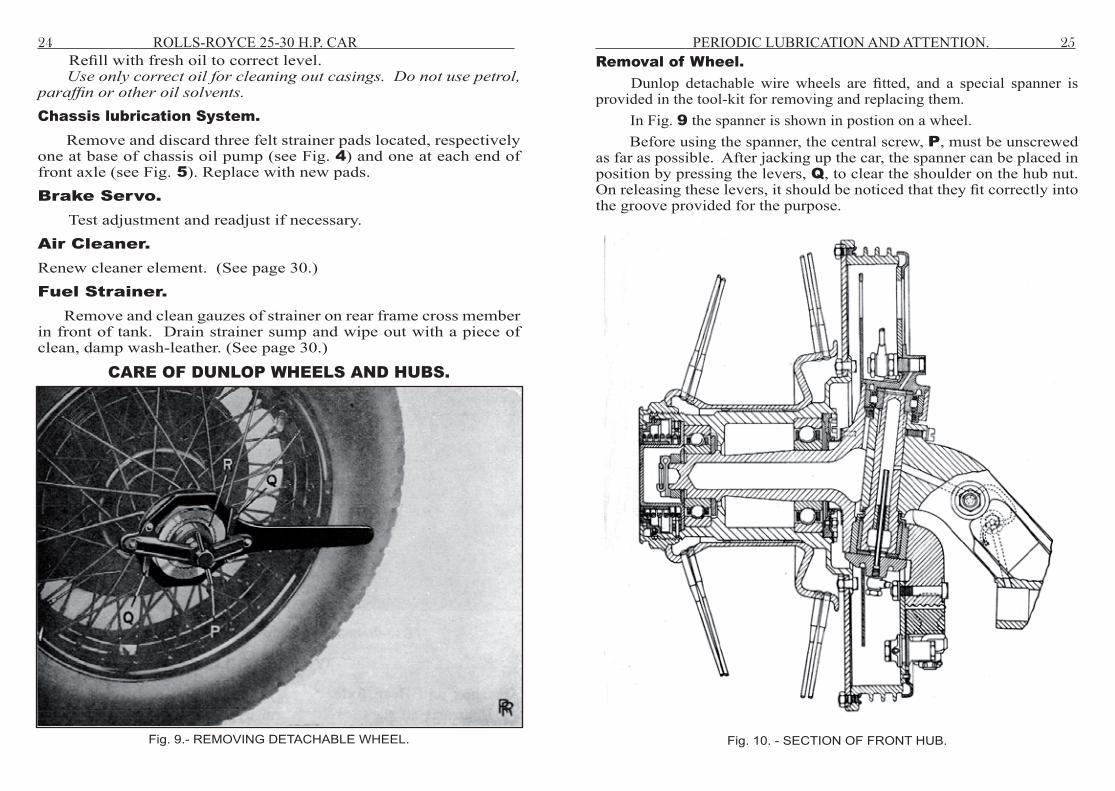
Fig. 10. - SECTION OF FRONT HUB.

26 ROLLS-ROYCE 25-30 H.P. CAR Screw P should then be turned until the serrations of the locking plate R, are seen to be clear of those on the hub nut. The latter can then be turned in an anti-clockwise direction and the wheel withdrawn, the hub nut remaining in the spanner. The thread of the hub nut is right-handed for all wheels. When replacing a wheel, care must be taken that the engaging surfaces, serrations and threads of both hub and wheel are free from road grit and other foreign matter. Preferably, they should be slightly greased.
Fig. 11 - SECTION OF THE REAR HUB.
The hub nuts must be tightly screwed up by means of the special spanner, and the use of the mallet in conjunction with it, to ensure absolute tightness.
PERIODIC LUBRICATION AND ATTENTION. 27
The locking plate should now be allowed to come forward by turning the small lever, P, in an anti-clockwise direction, in order that its serrations shall engage those of the hub nut. It should be observed that when jacking up a rear wheel care is necessary that the head of the jack is arranged in the proper position. It should be imediately under the axle, between the two “U” bolts which secure the axle and spring together.Care of Wheels. Every 2,000 miles, the hub nuts should be tested for tightness with the spanner. On no account should the car ever be run with a wheel even slightly loose, as this will cause irreperable damage to the serrations and screw threads. It is necessary to try each hub nut periodically with the spanner, and tighten if necessary. In order to tighten the hub nut, it is necessary for the locking plate to be forced back by means of rotation of the small lever, P, until its serrarions are disengaged from those of the hub nut.Lubrication of Wheel Bearings. The wheel bearings are filled with ball-bearing grease in the first instance, and should run a long period without attention. Sections of the front and rear hubs are given in Figs. 10 and 11 respectively.Replacement Tyres. Wheels are 19” well-base rims and Dunlop C type tyres, size 6.00-19, are fitted. With regard to inner tubes, it is only necessary to state the size and to mention “well-base”. Tubes made for flat-base rims should not be used.Inflation of Tyres. The pressure for the 6.00-19 Dunlop C tyres should be as follows:- Front tyres, open and closed cars ... 30 lbs. per sq. inch. Rear tyres, open and closed cars ... 35 lbs. per sq. inch.Balancing the Road Wheels. It is most important, in view of the high speeds attainable, that the road wheels should be properly balanced. Therefore it is necessary to have all wheels balanced and to re-balance a wheel after changing its tyre. An out-of-balance effect is usually present in the complete wheel and tyre due to:-

28 ROLLS-ROYCE 25-30 H.P. CAR
(a) The valve and its patch on the inner tube; (b) The joint of the inner tube; and (c) Unavoidable irregularities in the outer cover due to move- ment of the material during vulcanising.
Fig. 12 - WIRE WHEEL WITH BALANCE WEIGHTS. A red spot on the outer cover wall indicates its lightest part, and the cover should be fitted so that the red spot is at the valve position. To correct such out-of-balance, three bolts are provided, spaced at equal intevals around the wheel rim, as shown at S, T and U in Fig. 12, and each carries a number of lead washers, enclosed by a metal cover. One of the bolts, T, is shown with its cover and washers dismantled. The parts are assembled on the bolt in the following order:- I. Rubber washer, TI, which acts as a seal against the ingress of water. 2. Special steel washer, T2, which forms a firm base for the cover and the lead washers.
3. Lead balancing washers, T3, up to seven in number on any one bolt. 4. Steel washer, T4. 5. Nut, T5, for retaining lead washers. 6. Cover, T6. 7. Steel Washer, T7. 8. Cap nut, T8, for retaining cover. To balance a wheel, all the lead washers should first be removed from each bolt, the other parts being fitted as indicated above. The front axle being jacked up, the wheel must be turned gently and allowed to come to rest. The lowest point of the tyre should then be marked. The operation should be repeated, and if the original mark returns to the bottom position, one or more lead washers should be added to the bolt on the opposite side of the wheel. If the mark made on the tyre is adjacent to the bolt, then one lead washer should be fitted on each of the other two bolts. On the other hand, if no bolt should lie on the vertical centre line through the marked point on the tyre, the washers of the two bolts furthest from the mark must be altered, for instance, if the distance of one bolt from the centre line is approximately twice that of the other, two lead washers should be fitted on the bolt nearer to the centre line and one lead washer on the other bolt. This process should be continued until the wheel will remain in any position in which it may be brought to rest, the number of lead washers being kept down to a minimum consistent with good balance of the wheel.
PERIODIC LUBRICATION AND ATTENTION. 29