pex pipe design manual for water, oil, gas & industrial ... · this pex pipe design manual for...
TRANSCRIPT

PEX PIPE DESIGN MANUAL (HDB-Based)
For Water, Oil, Gas & Industrial Applications
2018

ii
Foreword
PEX PIPE DESIGN MANUAL (HDB-BASED)
FOR WATER, OIL, GAS & INDUSTRIAL APPLICATIONS
This Manual was developed and published with the technical help and financial support of the members of the PPI (Plastic Pipe Institute). The members have shown their interest in quality products by assisting independent standards-making and user organizations in the development of standards, and also by developing reports on an industry-wide basis to help engineers, code officials, and users. This Manual has been prepared by PPI as a service to the industry. The information in this manual is offered in good faith and believed to be accurate at the time of its preparation, but is offered “as is” without any express or implied warranty, including WARRANTIES OF MERCHANTABILITY AND FITNESS FOR A PARTICULAR PURPOSE. PPI intends to revise this Manual from time to time, in response to comments and suggestions from users of this document. Please send suggestions for improvements to PPI. Information on other publications can be obtained by contacting PPI directly or visiting the web site.
The Plastics Pipe Institute, Inc.
www.plasticpipe.org
This manual was first issued in August 2018.
© The Plastics Pipe Institute, Inc. 2018

iii
PEX PIPE DESIGN MANUAL (HDB-Based)
For Water, Oil, Gas & Industrial Applications
TABLE OF CONTENTS
LIST OF FIGURES .................................................................................................................... v
LIST OF TABLES ....................................................................................................................... vi 1.0 INTRODUCTION ............................................................................................................. 1
2.0 SCOPE............................................................................................................................ 1
3.0 PEX SYSTEM SOLUTIONS ............................................................................................ 2
3.1. PEX Solutions for Hot and Cold Water .................................................................. 2
3.2. PEX Solutions for Infrastructure Applications ........................................................ 4
3.3. PEX Solutions for Industrial Applications ............................................................... 6
4.0 PRESSURE RATINGS FOR PEX PIPES ....................................................................... 7
4.1. ASTM Pressure Rating Method ............................................................................. 7
4.2. ISO Pressure Rating Method ............................................................................... 11
5.0 PEX PIPES: DIMENSIONS ........................................................................................... 11
6.0 PEX PIPES: PROPERTIES .......................................................................................... 11
6.1. General PEX pipe properties ............................................................................... 11
6.2. PEX Engineering Properties ................................................................................ 12
6.3. PEX Head loss data charts for full flow conditions ............................................... 16
7.0 PEX PIPES: DESIGN CONSIDERATIONS ................................................................... 17
7.1. Water Design Considerations .............................................................................. 17
7.2. Slurry Design Considerations .............................................................................. 20
7.3. Surge Pressure (Water Hammer) ........................................................................ 22
7.4. Vacuum/Suction Pipelines ................................................................................... 27
7.5. Non-Restrained Fittings and Pullout Prevention Techniques ............................... 29
7.6. Inclined Pipes, Dewatering and High-Gradient Supply Lines ............................... 34
7.7. Instructions for Underground Installation of PEX Piping System ......................... 43
7.8. Above-Ground Installation Guidelines ................................................................. 44
8.0 PEX FITTINGS .............................................................................................................. 56
8.1. PE100 Electrofusion fittings ................................................................................. 56
8.2. PEX-Lined Fittings ............................................................................................... 58
8.3. Flared End Connectors ........................................................................................ 59

iv
8.4. Brass Fittings for PEX Pipes ................................................................................ 60
8.5. Design Considerations for PEX Fittings ............................................................... 60
9.0 PRESSURE TESTS ...................................................................................................... 62
9.1. Test purpose: ....................................................................................................... 62
9.2. Test procedure: .................................................................................................... 62
9.3. Temporarily cover metal fittings (flanged couplings, branch-off saddles) to prevent excessive heat buildup due to exposure to sunlight. ............................................ 62
9.4. Pressure testing – see Tables 20 and 21: ........................................................... 62
9.5. After 3-4 cycles, rapidly lower the pressure to 75% of the working pressure by letting water out of the line. .................................................................................. 63
10.0 PEX CHEMICAL RESISTANCE .................................................................................... 63
APPENDIX A – Tables of Dimensions ..................................................................................... 64
A.1 IPS Pipe Sizes ..................................................................................................... 64
A.2 Metric Pipe Sizes ................................................................................................. 70
APPENDIX B – Flow Rate Tables............................................................................................ 75
v
LIST OF FIGURES
Figure 1. Infrastructure-hot water installation example .............................................................. 2 Figure 2. Riser system installation example ............................................................................... 3 Figure 3. PEX Infrastructure Application .................................................................................... 4 Figure 4. Pumping water from Borehole .................................................................................... 6 Figure 5. Industrial installation example showing a variety of fittings ........................................ 7 Figure 6. Pre-Insulated PEX Pipe ............................................................................................ 29 Figure 7. Fixpoint Clamp .......................................................................................................... 31 Figure 8. Floating Fixpoint Device............................................................................................ 32 Figure 9. Pullout Prevention Device ......................................................................................... 32 Figure 10. Floating Fixpoint Device with Flanges..................................................................... 33 Figure 11. Flared End Connector ............................................................................................. 33 Figure 12. Fixpoint Bridge ........................................................................................................ 33 Figure 13. Fixpoint Bridge Diagram ......................................................................................... 34 Figure 14. Using a Fixpoint Bridge in a Dewatering line .......................................................... 42 Figure 15. Maximum Support Distance - IPS sizes .................................................................. 47 Figure 16. Maximum Support Distance - Metric sizes .............................................................. 48 Figure B - 1. IPS Sizes - DR 21 ............................................................................................... 76 Figure B - 2. IPS Sizes - DR 17 ............................................................................................... 77 Figure B - 3. IPS Sizes – DR 13.5............................................................................................ 78 Figure B - 4. IPS Sizes - DR 11 ............................................................................................... 79 Figure B - 5. IPS Sizes - DR 9 ................................................................................................. 80 Figure B - 6. IPS Sizes - DR 8.3 .............................................................................................. 81 Figure B - 7. IPS Sizes - DR 7.3 .............................................................................................. 82 Figure B - 8. Metric Sizes – DR 26 ........................................................................................... 83 Figure B - 9. Metric Sizes - DR 16.2 ........................................................................................ 84 Figure B - 10. Metric Sizes – DR 13.6 ...................................................................................... 85 Figure B - 11. Metric Sizes – DR 11 ......................................................................................... 86 Figure B - 12. Metric Sizes - DR 9 ........................................................................................... 87 Figure B - 13. Metric Sizes – DR 7.4 ........................................................................................ 88 Figure B - 14. Metric Sizes – DR 6........................................................................................... 89

vi
LIST OF TABLES
Table 1. Maximum operating pressures (MOP) for conveying water in PEX pipes, with a design
factor (DF) = 0.5 and temperature of 73ºF .................................................................... 9 Table 2. Maximum operating pressures (MOP) for conveying water in PEX 0008 pipes, with a
design factor (DF) = 0.5 and DR of 11 ........................................................................ 10 Table 3. Elastic Modulus (psi) vs. Temperature T (oF) ............................................................ 13 Table 4. Elastic Modulus (MPa) vs. Temperature (oC) ............................................................ 14 Table 5. Reduction factors as a Function of Temperature ....................................................... 17 Table 6. Replacing Carbon Steel Slurry Pipes with PEX Pipes (IPS) ...................................... 21 Table 7. Replacing Carbon steel slurry pipes with PEX pipes (Metric) .................................... 21 Table 8. Correction Factors for Abrasion ................................................................................. 22 Table 9. Surge Pressures in PEX Pipes (Line Velocity = 3 ft/sec.) .......................................... 25 Table 10. Surge Pressures in PEX pipes ................................................................................. 26 Table 11. Towing of empty PEX pipe – maximum allowable length for all DRs ....................... 42 Table 12. Trench width ............................................................................................................ 43 Table 13. Coefficients .............................................................................................................. 46 Table 14. Correction factors ..................................................................................................... 49 Table 15. Initial Short-term thermal stresses ........................................................................... 51 Table 16. Sum of values .......................................................................................................... 52 Table 17. Sum of values .......................................................................................................... 53 Table 18. Working Pressures (psig) ......................................................................................... 58 Table 19. Working Pressures (bar) .......................................................................................... 58 Table 20. Pressure test – psig ................................................................................................. 63 Table 21. Pressure test – bar ................................................................................................... 63 Table A - 1. Comparison of Class, Pipe Series and Dimension Ratio ...................................... 64 Table A - 2. PEX IPS Pipe Properties – DR 26 ........................................................................ 65 Table A - 3. PEX IPS Pipe Properties – SDR 21 ..................................................................... 65 Table A - 4. PEX IPS Pipe Properties – SDR 17 ..................................................................... 66 Table A - 5. PEX IPS Pipe Properties – DR 15.5 ..................................................................... 66 Table A - 6. PEX IPS Pipe Properties – SDR 13.5................................................................... 67 Table A - 7. PEX IPS Pipe Properties – SDR 11 ..................................................................... 67 Table A - 8. PEX IPS Pipe Properties – SDR 9 ....................................................................... 68 Table A - 9. PEX IPS Pipe Properties – DR 8.3 ....................................................................... 68 Table A - 10. PEX IPS Pipe Properties – DR 7.3 ..................................................................... 69 Table A - 11. PEX IPS Pipe Properties – DR 6 ........................................................................ 69 Table A - 12. PEX PIPE Properties – SDR 26 (Series 12.5) .................................................... 70 Table A - 13. PEX PIPE Properties – SDR 21 (Series 10) ....................................................... 71 Table A - 14. PEX PIPE Properties – DR 16.2 (Series 7.6) ..................................................... 71 Table A - 15. PEX PIPE Properties – DR 13.6 (Series 6.3) ..................................................... 72 Table A - 16. PEX PIPE Properties – SDR 11 (Series 5) ......................................................... 72 Table A - 17. PEX PIPE Properties – SDR 9 (Series 4) ........................................................... 73 Table A - 18. PEX PIPE Properties – DR 7.4 (Series 3.2) ....................................................... 73 Table A - 19. PEX PIPE Properties – DR 6 Series 2.5) ........................................................... 74

1
PEX PIPE DESIGN MANUAL (HDB-BASED)
FOR WATER, OIL, GAS & INDUSTRIAL APPLICATIONS
1.0 INTRODUCTION
Polyethylene (PE) has been the material of choice for pressure piping applications such as water and oil/gas for over 40 years, both in North America and internationally. PE materials can be crosslinked to achieve even higher performance properties as crosslinked polyethylene (PEX). Crosslinking the PE molecules in a three-dimensional network results in a broader operating temperature range. These enhanced properties make PEX pipe more cost competitive with steel pipe, while maintaining all the benefits of plastic piping for water, industrial, mining, underground fire extinguishing lines, and oil and gas applications. PEX pipe has an excellent global reputation based on accredited international standards in more than 40 countries, along with decades of proven track record with established end users around the world.
2.0 SCOPE
This PEX PIPE DESIGN MANUAL For Water, Oil, Gas, and Industrial Applications describes PEX pipes that are used in a wide range of operating temperatures from -58ºF to 200ºF (-50ºC to 93ºC), in a variety of nominal pipe sizes (NPS) and dimension ratios (DR’s) ranging from NPS 3 to NPS 54 for inch pipe sizes and DN 75 to DN 1000 for metric pipe sizes, and pipes that are joined by the electrofusion process or mechanical fittings. Large diameter PEX pipe systems provide cost-effective, long-term solutions for various infrastructures, such as water, oil, gas, fire protection, industrial, and mining sectors throughout the world. For gas distribution applications, US Department of Transportation Pipeline and Hazardous Materials Safety Administration (PHMSA) requires a special permit, and Canadian regulators require a variance. This PEX PIPE DESIGN MANUAL (HDB-Based) reviews the pressure rating of PEX pipes obtained from the North American method called the HDB (hydrostatic design basis) using ASTM D2837. A similar PEX PIPE DESIGN MANUAL (MRS-Based) reviews the pressure rating of PEX pipes obtained with the ISO method called the MRS (minimum required strength) based on ISO 9080 and ISO 12162. The pressure rating criteria of the two pressure rating methods should not be interchanged. These Manuals also discuss key PEX physical properties, such as its resistance to slow crack growth (SCG) and rapid crack propagation (RCP). Pressure rating, SCG and RCP are three very important attributes for a plastic pipe used in large-diameter pressure pipe applications. Smaller diameter PEX tubing, such as those covered in ASTM F876 (NTS 1/8 to 6), is discussed in the “PPI DESIGN GUIDE for Residential PEX Water Supply Plumbing Systems” and numerous other PPI documents. In general, PEX tubing is commercially available in sizes up to and including NTS 4 and PEX pipe is available in large diameters NPS 3 and above. This document does not attempt to address the typical applications of copper tube size (CTS) PEX tubing as per ASTM F876 such as potable water, water service lines, residential fire protection, hydronic radiant heating and cooling, and geothermal ground loop piping.
2
For PEX materials, “tubing” refers to products whereby the actual outside diameter (OD) is 1/8 inch larger than the nominal size, which is the same as that for copper water tube, thus commonly referred to copper tube size (CTS). Product standards ASTM F876 and CSA B137.5 apply to PEX tubing. “Pipe” refers to products whereby the actual OD matches that of steel or iron pipe of the same nominal size, commonly referred to as iron pipe size (IPS). ASTM F2788, F2905, and F2968 and CSA B137.19 apply to PEX pipe. The terms “pipe” and “piping”, as well as “tube” and “tubing”, are used interchangeably in this document.
3.0 PEX SYSTEM SOLUTIONS
3.1. PEX Solutions for Hot and Cold Water
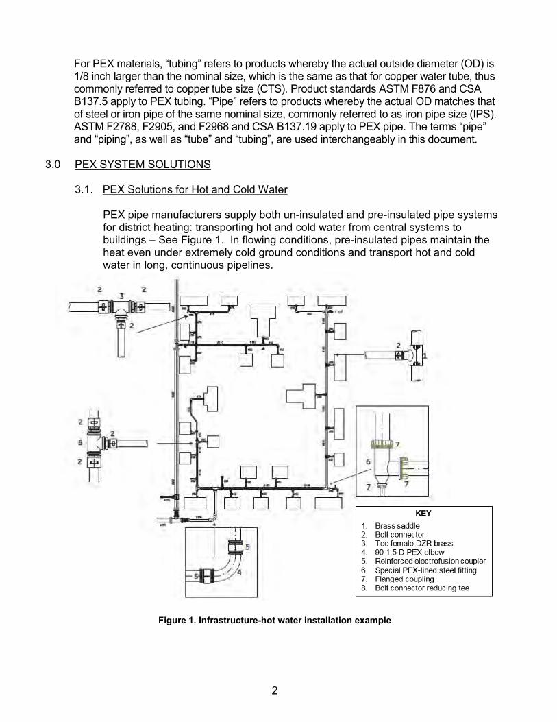
PEX pipe manufacturers supply both un-insulated and pre-insulated pipe systems for district heating: transporting hot and cold water from central systems to buildings – See Figure 1. In flowing conditions, pre-insulated pipes maintain the heat even under extremely cold ground conditions and transport hot and cold water in long, continuous pipelines.
Figure 1. Infrastructure-hot water installation example

3
3.1.1. Hot-Water Risers PEX pipes may be used for closed-loop and open-loop risers – see Figure 2. The pipes can be supplied in coils with all the required brass fittings including branch-off saddles, reducing tees, and more.
Figure 2. Riser system installation example

4
3.2. PEX Solutions for Infrastructure Applications Complete cold-water supply systems and industrial pipelines can be created by combining PEX pipes and PE (up to 140°F) or PEX (up to 200°F) electrofusion fittings – see Figure 3. Installation guidelines and electrofusion joining instructions are available from the pipe and fitting manufacturers.
Figure 3. PEX Infrastructure Application

5
3.2.1. PEX fire extinguishing lines PEX pipes offer complete solutions with electrofusion fittings and outlets for use in fire protection lines, such as underground water supply for fire extinguishing lines. PEX pipes and fittings should be third-party listed and/or approved (e.g. by UL or FM) for fire protection systems.
3.2.2. PEX lines for very low ambient temperatures Specially designed pre-insulated PEX pipes can be installed above ground in very low ambient temperatures to maintain the fluid’s temperature in flowing conditions over relatively long distances. PEX pipes are suitable for industrial and infrastructure applications for operating temperatures as low as -58ºF (-50ºC).
3.2.3. Oil and Gas/ Natural gas pipes
PEX pipelines designed for gas gathering or oil/gas applications shall meet the requirements of ASTM F2968, ASTM F2905, or ISO 14531. The main advantages of PEX pipes for these applications are:
3.2.3.1. Maximum service temperature of 200ºF (93ºC). Note –
applications above 200°F (93°C) require special design consideration.
3.2.3.2. Minimum service temperature of -58ºF (-50ºC). 3.2.3.3. No sand bedding is needed due to SCG resistance – see ISO
14531-4. 3.2.3.4. PEX pipes may be joined by PE or PEX electrofusion fittings,
based on temperature requirements. 3.2.3.5. RCP arrest temperature as low as -58ºF (-50ºC).
3.2.4. Dewatering Lines
PEX pipes are a good solution for dewatering lines in mining applications. They can be supplied in various pressure ratings in long continuous lengths and can be dragged on the ground to the final location. PEX pipes are easily installed, as they do not require anchoring. The end fittings should be protected by a pullout prevention technique such as fixpoints. Fittings along the line should be protected by a floating fixpoint device.
3.2.5. Riser Mains for Wells/Boreholes
PEX pipes may be used for pumping water from water boreholes – see Figure 4. The pipes are generally supplied with special borehole fittings.

6
Figure 4. Pumping water from Borehole
3.3. PEX Solutions for Industrial Applications PEX pipes, with excellent resistance to temperature extremes, chemicals and abrasion, have been shown to be excellent candidates for a wide range of industrial applications. Examples include transporting slurries, gypsum, sand, salt, phosphates, silts, potash, various chemicals, and industrial wastes. See Figure 5 for an example of an industrial application. PEX pipes offer successful, cost-effective solutions where other pipes would be unsatisfactory for conveying slurries, either due to their lower abrasion resistance or because of vulnerability to chemicals.

7
Figure 5. Industrial installation example showing a variety of fittings 4.0 PRESSURE RATINGS FOR PEX PIPES
The pressure rating of PEX pipes covered by this document is obtained by the hydrostatic design basis (HDB) method as defined by ASTM D2837. 4.1. ASTM Pressure Rating Method
4.1.1. Standard 73°F (23°C) HDB Rating
ASTM Test Method D2837 “Standard Test Method for Obtaining Hydrostatic Design Basis for Thermoplastic Pipe Materials or Pressure Design Basis for Thermoplastic Pipe Products” (originally published 1969) contains a procedure for obtaining a long-term hydrostatic strength category based on stress, referred to herein as the hydrostatic design basis (HDB). According to D2837, “The HDB is a material property and is obtained by evaluating stress rupture data derived from testing pipe
SUPPORTS & GUIDES FIXPOINTS
KEY
1. Flared end connector with a loose flange
2. 90 degree -1.5D radius elbow with two flared ends and two loose flanges
3. PEX-lined fitting (equal Tee with a reducer) – see 8.2.
4. Pipe spool with one flared end & a loose flange
5. Flanged coupling (used for “field welding” adjustment)
6. 90 degree -3 D radius elbow with two flared ends and two loose flanges
7. Pipe spool with two flared ends & two loose flanges
8. Stainless steel branch-off saddle with 2” flanged outlet
9. Standard PEX-lined lateral Tee 10. Long spool with a natural bend & a
flared end connector with a loose flange
11. Standard PEX-lined 1.5D elbow 12. Standard PEX-lined concentric
reducer 13. Pipe spool with one flared end & a
loose flange 14. Electrofusion coupling 15. 90 degree -3 D radius elbow with two
flared ends and two loose flanges

8
made from the subject material. The LTHS is determined by analyzing stress versus time-to-rupture (that is, stress-rupture) test data that cover a testing period of not less than 10,000 hours and that are derived from sustained pressure testing of pipe made from the subject material. The data are analyzed by linear regression to yield a best-fit log-stress versus log time-to-fail straight-line equation.” This method utilizes pipe specimens tested at a constant temperature with the linear log stress—log time regression line extrapolated to 100,000 hours (11 years). This extrapolated value is called the long-term hydrostatic strength (LTHS) and the categorized value of the LTHS is called the Hydrostatic Design Basis (HDB). When data are analyzed and approved by the PPI’s Hydrostatic Stress Board, these HDB values are published in PPI TR-4 “PPI Listing of Hydrostatic Design Basis (HDB), Strength Design Basis (SDB), Pressure Design Basis (PDB) and Minimum Required Strength (MRS) Ratings for Thermoplastic Piping Materials or Pipe”, which is available at www.plasticpipe.org. The hydrostatic design stress (HDS) is the product of the HDB and the design factor (DF) for water. The design factor (DF) for water, and other service applications and conditions, is defined within PPI Technical Report TR-9, Recommended Design Factors for Pressure Applications of Thermoplastic Pipe Materials. The design engineer uses the maximum operating pressure Equation 1 below to calculate the maximum operating pressure (MOP), for the PEX pipe:
MOP = [2 (HDB) (DF) / (DR – 1)] (Eq. 1)
Where: MOP = maximum operating pressure, psig
HDB = hydrostatic design basis, psi DF (design factor) = 0.5 for water or gas gathering pipe DR = dimension ratio
An example calculation for a DR 11 PEX pipe with an HDB of 1600 psi at 73oF (23oC) is:
P = [2 (1600) (0.5) / (11-1)] = 160 psig. This is the maximum operating pressure or pressure rating for DR 11 PEX pipe using the recommended design factor (DF) of 0.5 for water or oil and gas piping applications. An example calculation for a DR 7 PEX pipe with an HDB of 1600 psi is:
P = [2 (1600) (.5) / (7-1)] = 266 psig.

9
Table 1 shows examples of the pipe MOP for PEX pipe with an HDB of 1600 psi and a DF of 0.5 for 73°F as a function of the pipe DR.
Table 1. Maximum operating pressures (MOP) for conveying water in PEX pipes, with a design factor (DF) = 0.5 and temperature of 73ºF
Pipe DR MOP (psig) 6 320 7 266 9 200
11 160 13.6 125 16.2 105 21 80 26 64
PEX pipes can be operated at a temperature as low as -58ºF (-50ºC). The pressure rating remains the same at these lower temperatures. Even though the pipe is stronger at the lower temperatures and could have a higher pressure rating, the ASTM methodology does not account for this increased strength at lower temperatures. The HDB for a pressure pipe material must always be determined at 73°F. It is important to note that the Thermoplastic Pipe Material Designation Code, as shown in the applicable ASTM PEX standards, is ONLY determined using the HDB at 73°F.
4.1.2. Elevated Temperature HDB Ratings If a material is also intended for use at higher temperatures (above 73°F), then an elevated temperature HDB should be established. The elevated temperature HDB method is discussed in more detail in PPI TR-9 “Recommended Design Factors and Design Coefficients for Thermoplastic Pressure Pipe”. The elevated temperature HDB establishes the Hydrostatic Design Basis for the specific material at chosen higher temperatures. The procedures of ASTM Test Method D2837 are still employed, using actual test temperatures of 140°F (60°C) or 180°F (82°C) or another test temperature as desired. The design engineer uses the maximum operating pressure Equation 2 below to calculate the maximum operating pressure (MOP) at the elevated temperature for the PEX pipe. In the example below, HDB180 is the HDB at 180°F:
MOP = [2 (HDB180) (DF) / (DR – 1)] (Eq. 2)
Table 2 shows examples of the pipe MOP for PEX pipe with a DF of 0.5 for DR 11 pipe as a function of temperature and the corresponding HDB at that temperature.

10
Table 2. Maximum operating pressures (MOP) for conveying water in PEX 0008 pipes, with a design factor (DF) = 0.5 and DR of 11
HDB Temperature (°F) HDB (psi) MOP (psig) 73 1600 160
140 1000 100 180 800 80 200 630 63
PPI TR-9 also describes a method for determining a temperature design factor (DFT), to be applied if the service temperature exceeds the maximum established elevated temperature HDB. However, as stated in PPI TR-9, “Temperature design factors should only be used when an established HDB is not available at the desired temperatures.” Elevated temperature HDB values are published in PPI TR-4 for PEX pipe materials that have been tested at those temperatures. PPI TR-3 also provides a method for determining the HDB at an intermediate temperature between 73°F and an elevated temperature (e.g. 180°F) by using the principles of mathematical interpolation.
4.1.3. The PEX Thermoplastic Pipe Material Designation Code The PEX Thermoplastic Pipe Material Designation Code, per the applicable ASTM standard, is the abbreviation for the material - PEX - followed by four numerals. The first numeral refers to chlorine resistance in one of four categories, when tested in accordance with ASTM Test Method F2023 and evaluated in accordance with the applicable ASTM product standard (e.g. F2788):
A digit “0” indicates that the PEX pipe either has not been tested for
chlorine resistance or does not meet the minimum requirement for chlorine resistance.
A digit “1” indicates the PEX pipe has been tested and meets the applicable ASTM PEX standard requirement for minimum chlorine resistance at the end use condition of 25% of the time at 140°F (60°C) and 75% at 73°F (23°C).
A digit “3” indicates that the PEX pipe has been tested and meets the applicable ASTM PEX standard requirement for minimum chlorine resistance at end use condition of 50% of the time at 140°F (60°C) and 50% at 73°F (23°C).
A digit “5” indicates that the PEX pipe has been tested and meets the applicable ASTM PEX standard requirement for minimum chlorine resistance at end use condition of 100% of the time at 140°F (60°C).

11
The second numeral refers to UV resistance in one of four categories, when tested in accordance with ASTM Test Method F2657 and evaluated in accordance with ASTM F2788: A digit “0” indicates that the PEX pipe either has not been tested for
UV resistance or does not meet the next category for UV resistance. A digit “1” indicates that the PEX pipe meets the requirements for 1
month UV resistance. A digit “2” indicates that the PEX pipe meets the requirements for 3
months UV resistance. A digit “3” indicates that the PEX pipe meets the requirements for 6
months UV resistance. The third and fourth numerals of the PEX Thermoplastic Pipe Material Designation Code refer to the HDS for water at 73°F in hundreds of psi, with tens and units of measure omitted. The HDS is the HDB times the design factor for water, for example 0.50. See ASTM F412 for full explanation of the Thermoplastic Pipe Material Designation Code
4.2. ISO Pressure Rating Method The ISO MRS pressure rating method is discussed in “PEX PIPE DESIGN MANUAL (MRS-Based) For Water, Oil, Gas & Industrial Applications”.
5.0 PEX PIPES: DIMENSIONS
Pipe dimension tables are in Appendix A for metric and inch-based pipe sizes. 6.0 PEX PIPES: PROPERTIES
6.1. General PEX pipe properties
Crosslinked polyethylene (PEX) is a polyethylene material that has undergone a change in molecular structure through processing whereby a majority (>65%) of the polymer chains are chemically linked. The crosslinked structure of the PEX pipe renders excellent properties such as: o Temperature operating range -58ºF to 200ºF (-50ºC to +93ºC)
Note: applications above 200ºF (93ºC) require special design consideration. o Corrosion resistance o Toughness o Chemical resistance o Very low friction coefficient: Hazen-Williams C= 150 to 155 o Abrasion resistance o Longevity o Resistance to slow crack growth (SCG) o Low creep o Resistance to rapid crack propagation (RCP)

12
These properties provide important advantages compared to standard HDPE pipes, as discussed in PPI TN-17.
6.2. PEX Engineering Properties 6.2.1. PEX Slow Crack Growth (SCG) Resistance
Slow crack growth (SCG) is a failure mechanism that can occur in the field with certain materials in certain circumstances. SCG resistance is a key material property of plastic piping materials because it is a factor in determining the pipe’s long-term performance. When higher operating pressures or larger diameter pipes are being considered, SCG resistance is even more important. PEX is a modified polyethylene material, typically high- density polyethylene (HDPE), which has undergone a change in the molecular structure using a chemical or a physical process whereby the polymer chains are permanently linked to each other. This crosslinking of the polymer chains results in improved resistance to slow crack growth (SCG). During rehabilitation or other installation techniques, pipes can be scored, scratched or damaged on the outside surface. These external scratches could lead to slow crack growth and eventual failure of the pipe, unless the pipe has very high resistance to SCG. The higher SCG resistance of PEX pipes results in substantially improved long-term performance. This is especially important as PEX pipes are used in higher-pressure and higher-temperature applications. This higher SCG resistance typically allows PEX pipes to be installed using the natural backfill, including rocks. This has been a common practice in European countries, even for the gas distribution industry – see paper by Stefan Dreckoetter, “Exploring Boundries: Prolonged ISO 9080 Testing Revealing the Full Capabilities of PE-X”, presented at Plastics Pipe XVII. For gas distribution applications in the US, PHMSA (Pipeline and Hazardous Materials Safety Administration) requires a special permit, and Canadian regulators require a variance.
6.2.2. PEX Rapid Crack Propagation (RCP) Resistance RCP is a phenomenon in pressurized pipelines where an impact causes a crack to initiate and propagate at high speed, potentially for long distances, before arresting. There have not been any RCP failures reported in PEX pipes used in water or oil and gas piping systems. PEX pipe has been tested using ISO 13477, known as the S-4 or small-scale steady state test, to obtain the critical pressure or critical hoop stress. The critical pressure is the pressure below which RCP will arrest within the prescribed distance at a given temperature. For example, the

13
S-4 critical hoop stress for a particular PEX pipe at -58ºF (-50ºC) was determined to be 8 MPa (1160 psi). In DR 11 PEX pipes this is equivalent to an S-4 critical pressure of 16 bar (230 psig), which converts to a full-scale critical pressure of 900 psig using the ISO 13477 correlation equation. This high critical pressure means that for this PEX pipe, RCP will not be a concern, even at very low temperatures.
6.2.3. PEX Modulus of Elasticity
The modulus of elasticity is related to the Poisson ratio for plastic materials. For PEX pipes, the Poisson ratio is 0.4. Tables 3 and 4 below show the effect of temperature on short-term and long-term modulus of elasticity from 220ºF (100ºC) down to -58ºF (-50ºC) for a particular PEX pipe (values are rounded). These tables also show the coefficient of thermal expansion (α).
Table 3. Elastic Modulus (psi) vs. Temperature T (oF)
T oF Elastic Modulus [psi]
Long term Modulus [psi]
Coefficient of Thermal Expansion, α1/oF
220 6815 889 2.94E-04
200 8700 1056 2.39E-04
180 11165 1260 1.89E-04
160 14065 1513 1.61E-04
140 19720 1827 1.28E-04
120 27115 2221 1.11E-04
100 36540 3612 1.00E-04
73 61915 3612 7.94E-05
60 76995 4164 6.94E-05
40 108170 5219 5.78E-05
20 158630 6601 4.58E-05
0 276950 8434 3.58E-05
-20 476470 10894 2.61E-05
-40 1230470 15297 1.78E-05
-58 1348500 21242 6.67E-06

14
Table 4. Elastic Modulus (MPa) vs. Temperature (oC)
T oC Elastic Modulus [MPa]
Long term Modulus [MPa]
Coefficient of Thermal Expansion, α1/0C
100 54 7.1 4.70E-04 90 64 8 4.00E-04 80 81 9.1 3.40E-04 70 99 10.5 2.90E-04 60 136 12.1 2.30E-04 50 182 14.2 2.00E-04 40 228 16.8 1.80E-04 30 350 20 1.50E-04 20 465 24.2 1.40E-04 10 598 29.6 1.10E-04 0 894 36.7 9.80E-05
-10 1295 46.4 7.80E-05 -20 2064 59.7 6.30E-05 -30 3421 78.5 4.70E-05 -40 8486 105.5 3.20E-05 -50 9274 145.7 1.20E-05
6.2.4. PEX Thermal Conductivity
The heat conduction rate (Q) through the pipe wall can be established for the various pipe sizes as follows (see Equation 3).
Q = (Ti − To) / R (assuming that fluid in the pipe is at a higher temperature) (Eq. 3)
Where: Q = heat conduction rate Ti = inside temperature To = outside temperature R = termed as the thermal resistance of the pipe. See PPI TR-48 “R-Value and Thermal Conductivity of PEX and PE-RT” for additional information on the R-value.
R = ln [ro/ri] / 2πkL (Eq. 4)
Where: ro = outside pipe radius
ri = inside pipe radius L is the pipe length under consideration k = conductivity of pipe wall
15
Hence, for a unit length (L = 1)) of tubing and a ΔT of 1 degree C or F (Ti – To = 1), the heat conduction rate can be simplified to:
Q = 2πk / ln [ro/ri] (Eq. 5) Note: The heat conduction rate is for comparison purposes and not intended for use in
designing floor-heating systems. To calculate the heat output of a room other factors must be taken into account (i.e. material encasing the PEX pipe and floor coverings).
6.2.5. PEX Abrasion Resistance
Transporting solid materials by fluids in slurry form is common in industry, mining, and in many piping systems. In most cases, the flow is kept turbulent to avoid sedimentation. Abrasion is the result of the inner surface of the pipe wall being removed or degraded by flowing media (suspended solids) in the pipe. The rate of abrasion for various slurries is determined by many factors such as: Velocity Density of the particles Size distribution of the particles Hardness and angularity of the particles Temperature viscosity of the liquid Installation conditions
Abrasion resistance is one of the most important advantages of PEX pipes. PEX pipe’s excellent abrasion resistance is a result of the unique structure of crosslinked polyethylene, making the pipe material especially tough and resilient, and generally able to resist abrasion better than metal pipes. The ability of the pipe material to absorb the kinetic energy of the hard particles inside the slurry and its resistance to deformation make PEX pipes extraordinarily abrasion-resistant. Unavoidable scratches from abrasion in PEX pipes typically cause no failure. Results of tests performed on pipes after being subjected to notches (scratches) as deep as 20% of the pipe wall show that no significant reduction in strength was caused to the pipe during intensive pressure tests. The crosslinked molecular structure accounts for this insensitivity of PEX pipes to abrasion. The restraining action of the adjacent molecular chains of the crosslinked network absorbs the energy of the “tearing” forces. PEX pipe’s abrasion resistance was tested and approved in laboratory tests as well as in on-site conditions. For example in Israel’s Dead Sea Works, DN 450 PEX pipes were installed in 1985 and it has not yet been necessary to replace them. In comparison, steel pipes had to be replaced every year. These pipes are connected to dredgers, which “harvest” the salt particles. Non-crosslinked PE pipes, which were installed in these lines, failed after a few months.

16
As another example, DN 280 PEX pipes have been in operation since 1985 in a hot leech crystallization facility in the Dead Sea works, and as of 2017, it has not yet been necessary to replace them. Technical test reports and case studies concerning abrasion resistance of PEX pipes are available on request from the pipe manufacturer. See, for example, PPI TN-17 or Report GPW-11-2067 by Patterson & Cooke.
6.2.6. Lifetime estimations for PEX slurry pipeline With the above examples, PEX pipe has been shown to have an “abrasion allowance” of up to 20% of the nominal wall thickness of the pipe. This means that during its service lifetime, the wall thickness of the pipe could be reduced by abrasion until the remaining wall thickness is reduced to 80% of the nominal value. Consult the pipe manufacturer to determine the abrasion allowance for the particular PEX pipe. The actual lifetime of the pipe depends on the actual abrasion rate in the line. See “The Effect on the Wear Rate of High Density Polyethylene conveying South Mine Backfill Slurry”, Patterson & Cooke Consulting Engineers, Report WRR-018.R13, August 1994.
6.3. PEX Head loss data charts for full flow conditions The flow charts in Appendix B for PEX pipe provide information on discharge rates (GPM) as a function of head loss (expressed in percentage of the total line length) at various velocities for a variety of pipe sizes. The values of the head losses in these charts were calculated using the Hazen-Williams formula with Hazen-Williams coefficient C=155. Alternatively, these can be calculated using the following values of Absolute surface roughness: 0.00002-0.00003 inches (0.0005 mm–0.0007 mm). PPI’s website also provides a flow calculator for PEX pipe, www.plasticpipecalculator.com. 6.3.1. Reduction factors for higher temperatures
The values of the head losses in the flow charts are correct for 70º F (20ºC). At higher temperatures with reduced viscosity of water, the head losses are lower. For different temperatures, multiply the value of head loss by the temperature reduction factors in Table 5.
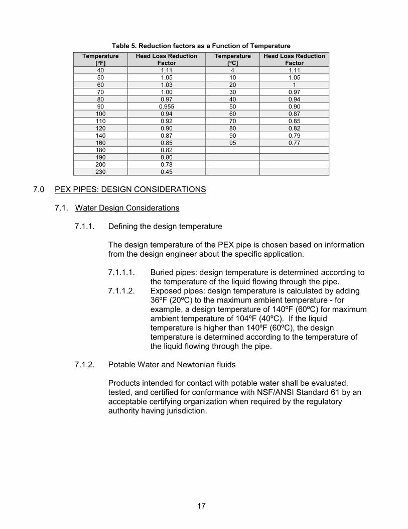
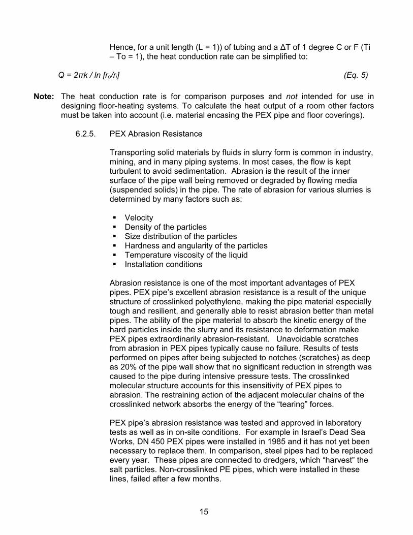
17
Table 5. Reduction factors as a Function of Temperature Temperature
[oF] Head Loss Reduction
Factor Temperature
[oC] Head Loss Reduction
Factor 40 1.11 4 1.11 50 1.05 10 1.05 60 1.03 20 1 70 1.00 30 0.97 80 0.97 40 0.94 90 0.955 50 0.90
100 0.94 60 0.87 110 0.92 70 0.85 120 0.90 80 0.82 140 0.87 90 0.79 160 0.85 95 0.77 180 0.82 190 0.80 200 0.78 230 0.45
7.0 PEX PIPES: DESIGN CONSIDERATIONS
7.1. Water Design Considerations
7.1.1. Defining the design temperature
The design temperature of the PEX pipe is chosen based on information from the design engineer about the specific application. 7.1.1.1. Buried pipes: design temperature is determined according to
the temperature of the liquid flowing through the pipe. 7.1.1.2. Exposed pipes: design temperature is calculated by adding
36ºF (20ºC) to the maximum ambient temperature - for example, a design temperature of 140ºF (60ºC) for maximum ambient temperature of 104ºF (40ºC). If the liquid temperature is higher than 140ºF (60ºC), the design temperature is determined according to the temperature of the liquid flowing through the pipe.
7.1.2. Potable Water and Newtonian fluids Products intended for contact with potable water shall be evaluated, tested, and certified for conformance with NSF/ANSI Standard 61 by an acceptable certifying organization when required by the regulatory authority having jurisdiction.

18
Local plumbing, mechanical and building codes must be consulted before beginning any piping project design. Codes are constantly reviewed and updated. The user must determine which codes are applicable to the specific project, and also must ensure compliance with all local, state, and federal codes, regulations and standards. Local code authorities and the product or system manufacturer should be consulted with respect to unresolved questions or uncertainties. Several industry standards, codes and regulations exist to guide industry professionals about the design and installation of PEX piping systems. These documents may be enforced as codes or referenced within codes and regulations for given jurisdictions. Designers, specifiers and installers must verify which standards, codes and regulations apply for the jurisdiction of each system. The following are recommended design guides for the operator for potable water and Newtonian fluids: 7.1.2.1. The pipe pressure rating or DR is selected according to
information from the design engineer about the specific application.
7.1.2.2. Pressure head losses in the line expressed in bars (taking into account the specific gravity of the transported material).
7.1.2.3. Design temperature (paragraph 1 above). 7.1.2.4. Basic design factor (DF) is 0.5. 7.1.2.5. Static pressure according to the altitude difference in the line
and the specific gravity of the transported material. 7.1.2.6. If the pipeline is horizontal and the static pressure is low,
select DR 26 and verify its suitability. 7.1.2.7. Choose a lower DR (thicker wall) with the same OD in order
to increase the transportable section lengths. 7.1.2.8. The hydraulic calculation (Hazen Williams) usually results in
the same OD. 7.1.2.9. If the altitude difference in the line is significant, select a PEX
pipe DR that has higher pressure rating than the static pressure for the specified design temperature. The additional pressure margin is used for the pressure head losses; this will determine the ID of the pipe.
7.1.2.10. The actual OD is determined by the DR of the PEX pipe chosen and the availability of this specific pipe diameter.
7.1.3. Replacing waterline steel pipes 7.1.3.1. When replacing steel pipes (Hazen-Williams C=110) with
PEX pipes (Hazen-Williams C=150 to 155) with the same pressure losses, the ID of the PEX pipe can typically be 88% of the ID of the existing steel pipe while delivering an equivalent flow rate.
19
7.1.3.2. When replacing steel pipes with PEX pipes with the same ID, the head losses are expected to be lower by 50%.
7.1.4. Influence of temperature changes on PEX pipes
7.1.4.1. PEX pipes placed above the ground or over bridges tend to
get longer (to expand) when temperature rises (snaking phenomenon) or to get shorter (contract) as the temperature decreases. Expansion or contraction does not change the performance properties of the PEX pipe, even in extremely low temperatures.
7.1.4.2. There is no need to protect the pipe against thermal stresses, as the pipe absorbs them.
7.1.4.3. Fixpoints or guiding clamps are used for restraining the elongation of the pipe (mainly for aesthetic considerations).
7.1.4.4. There is no need for installation of “expansion joints” or omegas.
7.1.4.5. Special fixpoint clamps should be used before and after the fittings (as recommended) to prevent the pipe from pulling out.
Please refer to “Fixpoint Clamps” in this manual for further information. See also the PPI Plastic Pressure Pipe Design Calculator at www.plasticpipecalculator.com.
7.1.5. PEX pipes above ground
7.1.5.1. PEX pipes, when recommended by the manufacturer, are
suitable for continuous outdoor use. Generally, carbon black is a good UV absorber for above ground applications.
7.1.5.2. PEX pipes can be placed directly on the ground. 7.1.5.3. Special bedding is not required. 7.1.5.4. Design temperature may be impacted by above-ground
installation. Please refer to Section 7.1.1 “Defining the Design Temperature”.
7.1.6. Pipes under full vacuum conditions Minimum pipe DR to assume that pipe will not collapse under vacuum: DR 11

20
7.1.7. PEX pipes at low temperatures PEX pipes may be used at temperatures as low as -58ºF (-50ºC) as specified in the relevant ASTM standards. Since the PEX material does not become brittle at these temperatures, it tolerates bending and dragging at low temperatures during installation. PEX pipes are freeze-break resistant and can generally tolerate complete ”homogeneous” freezing of the transported liquid. Homogeneous freezing takes place if the pipe is evenly exposed to low temperatures along the pipeline. However, if freezing starts at localized freezing points, the pressure of the fluid that is trapped between two adjacent freezing points increases until the pipe may burst. (This happens to any pipe material). Localized freezing points might be metal fittings (including PEX-lined steel fittings), fixpoint clamps or any point where the metal touches the pipe. Consequently, localized freezing points should be avoided or properly insulated. Please note that this applies to both above-ground and shallow underground installations.
7.2. Slurry Design Considerations
The pipe DR is determined based on the following data: o Working pressure o Design temperature o Chemical resistance of the pipe material to the slurry The pipe diameter is chosen based on the ID of existing steel pipe or on the value of the minimum critical slurry velocity. 7.2.1. Replacing carbon steel slurry pipes with PEX pipes with the same ID:
A slurry pipeline is designed according to the minimum critical velocity of the slurry material. Carbon steel slurry pipes can be replaced with PEX pipes of the same or slightly smaller nominal ID, maintaining the same slurry velocity. Tables 6 and 7 can be used as guidelines for choosing the suitable PEX pipes for replacing carbon steel slurry pipes according to the ID and flanges of existing steel pipe. The values of the ID of the PEX pipes in Tables 6 and 7 are nominal ID values, which were calculated based on the value of the nominal wall thickness of the pipe. The PEX pipes were chosen assuming that the working conditions of the existing steel pipes are appropriate for the PEX pipe pressure ratings listed here.

21
Table 6. Replacing Carbon Steel Slurry Pipes with PEX Pipes (IPS)
PEX loose
flanges PEX pipe
Sch. 40 Carbon steel pipe
Size ID
3" 3.5” 3” 3"
4" 4” 3.5” 3.5" 4” 4” 4” 4" 6" 5” 5” 5" 6" 6” 6” 6"
10" 8” 8” 8"
12" 10” 10” 10"
14" 12” 12” 12" 16" 14” 13” 14" 18" 16” 15” 16" 20" 18 16.85” 18"
Table 7. Replacing Carbon steel slurry pipes with PEX pipes (Metric)
PEX Loose
flanges
PEX Pipe (mm)
(Option 2)
PEX Loose
flanges
PEX Pipe (mm)
(Option 1)
Sch. 40 Carbon steel pipe
Size (mm) ID 4” 110 DR 7.4 3" 90 DR 11 78 3" 4” 125 DR 7.4 4" 110 DR 11 90 31/2"
6’” or 5” 140 DR 7.4 4” 125 DR 11 102 4" 6” 180 DR 7.4 6" 160 DR 11 128 5" 8” 200 DR 7.4 6" 180 DR 11 154 6" 10” 280 DR 7.4 10" 250 DR 11 202 8" 14” 355 DR 7.4 12" 315 DR 11 254 10" - - 14" 355 DR
13 6 303 12"
18” 450 DR 7.4 16" 400 DR 11 333 14" - - 18" 450 DR
13 6 381 16"
- - 20" 500 DR 13 6
428 18"
Abrasion allowance: PEX pipes have an “abrasion allowance” of up to 20% of the nominal wall thickness of the pipe – consult pipe manufacturer for their specific recommendation for their product. This means that even though the remaining wall thickness of the pipe is reduced to 80% of the nominal value, the pipe can withstand the design working pressure for 50 years. The 80% guideline (depending on manufacturer) applies for all working pressures and all temperatures in all DR’s. An increase in the ID of the PEX pipes due to abrasion results in a decrease in the velocity of the slurry. In order to make sure that the value of the minimum critical slurry velocity is maintained after 20% abrasion, the ID of the PEX pipe can be calculated by multiplying the Nominal PEX pipe ID by the correction factors in Table 8.

22
Table 8. Correction Factors for Abrasion Correction
Factor DR
1.016 26 1.021 21 1.028 17
1.0345 13.6 1.044 11 1.057 9 1.074 7.4
1.1 6
7.3. Surge Pressure (Water Hammer)
Water hammer is a series of pressure pulsations, of varying magnitude, above and below the normal pressure of the liquid in the pipe. Surge pressure results from these pulsations when any liquid, flowing with a certain velocity, is stopped in a short period of time. The amplitude and periodicity depends on the extinguished velocity of the liquid, as well as the size, length and material of the pipeline. The pressure increase, when flow is stopped, is independent of the working pressure of the system.
7.3.1. Calculation example for PEX pipe:
The surge pressure in any pipeline occurs when the total discharge is stopped in a period of time, equal to or less than the time required for the induced pressure wave to travel from the point of valve closure to the inlet end of the line and return. Here is an example calculation. The time (t) is:
t = 2L / a (Eq. 6)
Where: t = Time for pressure wave to travel the length of the pipe and return (sec.)
L = Length of pipe line (ft) a = Velocity of pressure wave (ft/sec)
When the liquid in the pipe is water, the velocity of the pressure wave “a” is determined by the following equation:
a = 4660 / [1 + Kbulk / E (DR - 2)]1/2 (Eq. 7)
Where: a = Velocity of pressure wave (ft/sec)
Kbulk = Bulk modulus of fluid (for example: 300,000 psi for water at 73ºF) E = Instantaneous term modulus of elasticity of pipe material (psi) obtained from Tensile tests

23
For E values - Please refer to tables 13 and 14 in this Manual DR = Pipe dimension ratio
The surge pressure caused by water hammer is determined by the following equation:
P = a ( V / 2.31g) (Eq. 8)
Where: P = Surge pressure (psi)
a = Velocity of pressure wave (ft/sec) V = Velocity of water stopped = line velocity (ft/sec) g = Acceleration caused by gravity (32.2 ft/sec2)
Pressure surges can be minimized by increasing closure times of valves to a value greater than 2L/a. For example, when the closure time is 10 times 2L/a, the pressure surge can be 10%–20% of the surge caused by closure in a time equal to or less than 2L/a. The value of the short-term modulus of elasticity E for PEX pipes is much lower than the value of E for steel pipes, concrete pipes or HDPE pipes. Since the velocity a of the pressure wave is related to the short-term modulus of elasticity E, the velocity a decreases when the value of E is lower. In order to determine the resistance of the pipe material to the pressure surges, the total recurring pressure (surge pressure + working pressure) should be calculated and compared to the maximum allowable total recurring pressure in each pipe material. The resistance of HDPE pipes depends on the nature of the water hammer. In case of recurring water hammer shockwaves, HDPE pipes are limited to a maximum total occasional pressure of only 1.5 times the working pressure. Because of the flexibility and resilience of PEX pipes, the surge pressures caused by the water hammer are much reduced. Furthermore, because of the crosslinked structure, the PEX pipe can withstand a total recurring pressure (recurring or occasional surge pressure + working pressure) at least 2.5 times the design pressure in the relevant temperature.
7.3.2. Calculation examples for various pipe:
The following examples show the pressure surges caused by the water hammer for various PEX pipes, which were considered for similar working conditions. In all following examples: The line is horizontal; line length is 7,200 ft (2,200 m). The flow rate is 660 gpm (150 cubic m per hour), head losses are 5%. The line is designed for a pump pressure of 160 psi (11 bar).

24
The pipes calculated for this application are as follows: 7.3.2.1. Steel pipe 6” schedule 40, buried pipeline or above ground
installation. OD 6.625”, w.t. 0.28", d = 6.065" = 0.505 ft, V= 7.35 ft/sec E= 30 x 106 psi
a= 4660 / [1 + 300,000 / 30 x 106 (6.625 / 0.28 - 2)]1/2 a= 4225 ft/sec t = 2L/a =2x7,200/4225= 3 sec P= 4225 (7.35 / 2.31 X 32.2) = 417 psi
The results are: surge pressure = 417 psi.
Total recurring pressure: surge pressure (417psi) + pump pressure in the line (160psi) is 577 psi.
7.3.2.2. PEX 6" DR 13.6, buried pipeline installation.
Maximum allowable working pressure of the pipe is 160 psi at 73ºF. Maximum allowable total transient pressure – 400 psi. OD 6.625", w.t. 0.487", d= 5.65", V= 8.45 ft/sec E=64,000psi at 73ºF a= 4660 / [1 + 300,000 / 64,000 (13.6 - 2)]1/2
a= 626 ft/sec t = 2L/a =2x7,200/626= 23 sec P= 626 (8.45 / 2.31 X 32.2) = 71 psi The results are: surge pressure = 71 psi Total recurring pressure: 71+160 = 231 psi. The total recurring pressure is much lower than the maximum allowable total recurring pressure (400 psi).
7.3.2.3. PEX 7" DR 9, above ground installation Ambient temperature is 100ºF, design temperature is 140ºF. Maximum allowable working pressure of the pipe is 100 psi at 140ºF. Maximum allowable total recurring pressure – 400 psi. OD 7.125", w.t. 0.792", d= 5.54", V= 8.8 ft/se E=20,000psi at 140ºF a = 4660 / [1 + 300,000 / 20,000 (9 - 2)]1/2 a = 453 ft/sec t = 2L/a =2x7,200/453= 32 sec
25
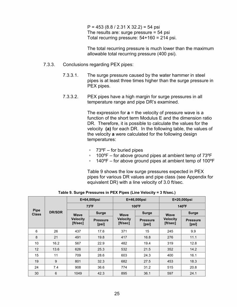
P = 453 (8.8 / 2.31 X 32.2) = 54 psi The results are: surge pressure = 54 psi Total recurring pressure: 54+160 = 214 psi. The total recurring pressure is much lower than the maximum allowable total recurring pressure (400 psi).
7.3.3. Conclusions regarding PEX pipes:
7.3.3.1. The surge pressure caused by the water hammer in steel
pipes is at least three times higher than the surge pressure in PEX pipes.
7.3.3.2. PEX pipes have a high margin for surge pressures in all
temperature range and pipe DR’s examined. The expression for a = the velocity of pressure wave is a function of the short term Modulus E and the dimension ratio DR. Therefore, it is possible to calculate the values for the velocity (a) for each DR. In the following table, the values of the velocity a were calculated for the following design temperatures: ▫ 73ºF – for buried pipes ▫ 100ºF – for above ground pipes at ambient temp of 73ºF ▫ 140ºF – for above ground pipes at ambient temp of 100ºF
Table 9 shows the low surge pressures expected in PEX pipes for various DR values and pipe class (see Appendix for equivalent DR) with a line velocity of 3.0 ft/sec.
Table 9. Surge Pressures in PEX Pipes (Line Velocity = 3 ft/sec.)
E=20,000psi E=46,000psi E=64,000psi
DR/SDR Pipe Class
1400F 1000F 730F
Surge Wave Velocity [ft/sec]
Surge Wave Velocity [ft/sec]
Surge Wave Velocity [ft/sec]
Pressure [psi]
Pressure [psi]
Pressure [psi]
9.9 245 15 371 17.6 437 26 6
11.1 276 16.8 417 19.8 491 21 8
12.8 319 19.4 482 22.9 567 16.2 10
14.2 352 21.5 532 25.3 626 13.6 12
16.1 400 24.3 603 28.6 709 11 15
18.3 453 27.5 682 32.3 801 9 19
20.8 515 31.2 774 36.6 908 7.4 24
24.1 597 36.1 895 42.3 1049 6 30

26
The value of a = Velocity of pressure wave was calculated using the instantaneous Modulus of Elasticity. Please note the surge pressure P is in direct linear relation to the value of the line velocity V. Therefore, values for different surge pressures for the same pipe DR can be calculated by changing the values of the Line velocity V. For example: calculating the surge pressure in the example 7.4.2.2 above. PEX 7" DR 9, above ground installation Ambient temperature is 100ºF, design temperature is 140ºF. Design pressure 100 psi at 140ºF maximum allowable total recurring pressure = 400 psi. OD 7.125", w.t. 0.792", d= 5.54", V= 8.8 ft/sec From Table 9, the surge pressure for DR 9, velocity of 3 ft/sec and design temperature of 140ºF is 18.3 psi. For the PEX 7" DR 9 which has a velocity of 8.8 ft/sec, the surge pressure will be: 18.3x8.8/3=53.7psi For fluid other than water, the value of the velocity of the pressure wave a, (taken from Table 9) should be divided by the square root of the actual fluid density. Table 10 shows the low surge pressures expected in PEX pipes.
Table 10. Surge Pressures in PEX pipes
E=136 MPa E=228 MPa E=465 MPa
DR/SDR Pipe Class
600C 400C 200C
Surge Wave Velocity [m/sec]
Surge Wave Velocity [m/sec]
Surge Wave Velocity [m/sec]
pressure [bar]
pressure [bar]
pressure [bar]
0.8 75 1 97 1.4 139 26 6
0.9 85 1.1 109 1.6 156 21 8
1 98 1.3 126 1.8 180 16.2 10
1.1 108 1.4 140 2 198 13.6 12
1.2 123 1.6 158 2.3 225 11 15
1.4 139 1.8 179 2.6 254 9 19
1.6 158 2.1 204 2.9 288 7.4 24
1.9 183 2.4 236 3.4 332 6 30
27
The value of a = Velocity of pressure wave was calculated using the instantaneous Modulus of Elasticity Please note the surge pressure P is in direct linear relation to the value of the line velocity (V). Therefore, values for different surge pressures for the same pipe class or DR can be calculated by changing the values of the Line velocity V. For example: calculating the surge pressure in example 7.3 Surge Pressure (Water Hammer) above: ▫ PEX 180 mm SDR 9 Class 19 ▫ Above ground installation: ambient temperature is 120ºF,
design temperature is 140ºF ▫ Design pressure of the pipe is 100 psig at 140ºF.
Maximum allowable total recurring pressure – 435 psig. ▫ OD 180 mm, w.t. 20.1 mm, d= 139.8 mm = 0.1398m, V=
2.7 m/sec ▫ From Table 10, the surge pressure for class 19, velocity
of 1 m/sec and design temperature of 60ºC (140F) is 1.6 bar (23 psig).
For the PEX 180mm Class 19 which has a velocity of 2.7 m/sec, the surge pressure will be: ▫ 1.6x2.7/1=4.3bar = 62 psig
For a water density higher than 1.0, divide the value of the velocity of the pressure wave, a, (from Table 10) by the square root of the actual water density.
7.3.4. Calculating PEX pipes for potable water boreholes
PEX pipes can be used as riser pipes for potable water boreholes. For energy-saving reasons, PPI recommends choosing a PEX pipe with head losses that do not exceed 5% pressure loss, and preferably lower. However, please note that designing these PEX pipes is complicated, due to the complex three-dimensional stress regime in these applications. PEX pipe manufacturers can calculate the pipe design for your particular application.
7.4. Vacuum/Suction Pipelines Under-pressure (vacuum) might develop in the following cases: 7.4.1. When a pipe is installed in vacuum-feeding pipelines. 7.4.2. When a pipe is installed in a steep inclination, causing rapid free flow. 7.4.3. Extreme temperature changes of the transported liquid.
28
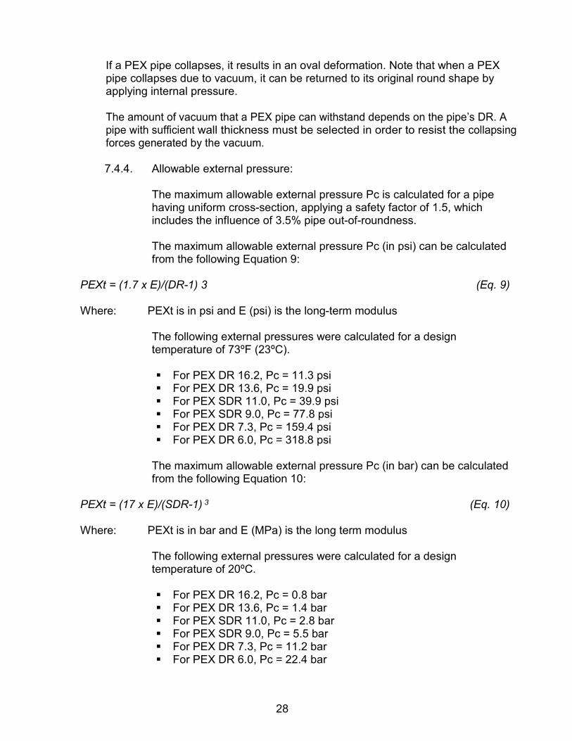
If a PEX pipe collapses, it results in an oval deformation. Note that when a PEX pipe collapses due to vacuum, it can be returned to its original round shape by applying internal pressure. The amount of vacuum that a PEX pipe can withstand depends on the pipe’s DR. A pipe with sufficient wall thickness must be selected in order to resist the collapsing forces generated by the vacuum.
7.4.4. Allowable external pressure:
The maximum allowable external pressure Pc is calculated for a pipe having uniform cross-section, applying a safety factor of 1.5, which includes the influence of 3.5% pipe out-of-roundness. The maximum allowable external pressure Pc (in psi) can be calculated from the following Equation 9:
PEXt = (1.7 x E)/(DR-1) 3 (Eq. 9)
Where: PEXt is in psi and E (psi) is the long-term modulus
The following external pressures were calculated for a design temperature of 73ºF (23ºC). For PEX DR 16.2, Pc = 11.3 psi For PEX DR 13.6, Pc = 19.9 psi For PEX SDR 11.0, Pc = 39.9 psi For PEX SDR 9.0, Pc = 77.8 psi For PEX DR 7.3, Pc = 159.4 psi For PEX DR 6.0, Pc = 318.8 psi
The maximum allowable external pressure Pc (in bar) can be calculated from the following Equation 10:
PEXt = (17 x E)/(SDR-1) 3 (Eq. 10)
Where: PEXt is in bar and E (MPa) is the long term modulus
The following external pressures were calculated for a design temperature of 20ºC. For PEX DR 16.2, Pc = 0.8 bar For PEX DR 13.6, Pc = 1.4 bar For PEX SDR 11.0, Pc = 2.8 bar For PEX SDR 9.0, Pc = 5.5 bar For PEX DR 7.3, Pc = 11.2 bar For PEX DR 6.0, Pc = 22.4 bar
29
For other design temperatures, use suitable values of the long-term modulus from tables 3 and 4.
7.4.5. Underground PEX pipe under vacuum or external pressures
Vacuum, or external pressures, creates hoop stresses in the pipe wall, which are combined with the external pressures of the soil. In extreme cases, these stresses can cause the pipe to collapse. Therefore, when a PEX vacuum pipeline is installed underground, the vacuum stresses have to be added to the total static and dynamic loads exerted by the soil and all the stresses must be considered. In this case, make sure that the soil around the pipe is compacted. When designing a vacuum pipeline at recommended vacuum conditions, please contact the manufacturer for consultation regarding installation of vacuum breakers.
7.4.6. PEX Pre-insulated Pipes for District Heating & Industrial Applications
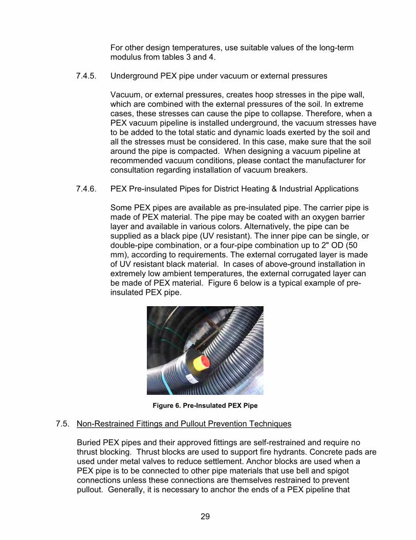
Some PEX pipes are available as pre-insulated pipe. The carrier pipe is made of PEX material. The pipe may be coated with an oxygen barrier layer and available in various colors. Alternatively, the pipe can be supplied as a black pipe (UV resistant). The inner pipe can be single, or double-pipe combination, or a four-pipe combination up to 2" OD (50 mm), according to requirements. The external corrugated layer is made of UV resistant black material. In cases of above-ground installation in extremely low ambient temperatures, the external corrugated layer can be made of PEX material. Figure 6 below is a typical example of pre-insulated PEX pipe.
Figure 6. Pre-Insulated PEX Pipe 7.5. Non-Restrained Fittings and Pullout Prevention Techniques
Buried PEX pipes and their approved fittings are self-restrained and require no thrust blocking. Thrust blocks are used to support fire hydrants. Concrete pads are used under metal valves to reduce settlement. Anchor blocks are used when a PEX pipe is to be connected to other pipe materials that use bell and spigot connections unless these connections are themselves restrained to prevent pullout. Generally, it is necessary to anchor the ends of a PEX pipeline that

30
transitions into an unrestrained joint pipe system, to minimum effects of thermal expansion and contraction. 7.5.1. Design of wall anchors and thrust blocks:
A typical anchoring technique is installing a fixpoint clamp or a flanged coupling on the pipe close to the wall, and pouring concrete around it.
7.5.2. Non-restrained fittings:
A different situation occurs in certain applications where axial forces, which are present in the pipe, may pull out the pipe from non-restrained joints. The axial forces may be a result of the following: Thermal deflection (contraction) due to temperature variations Ground movement and earthquakes Hoop expansion: The internal pressure expands the diameter (ever
so slightly) and tends to contract the pipe length in proportion to Poisson’s Ratio.
In dewatering or borehole applications, additional longitudinal forces might be present due to the weight of the pipeline, the weight of the water column, or pump weight. These axial forces could result in pulling out the pipe from a gasket joint or a complete pulling out of the PEX pipe from the fitting.
7.5.3. Buried applications: All PEX fittings that are approved for buried applications are considered as restrained connections and they do not require any pull-out prevention method in buried applications.
7.5.4. E.4 Above ground applications:
For the applications of horizontal pipelines and inclined pipelines (including dewatering lines) with a slope of up to 40 degrees, the following fittings are considered as restrained connections and do not require any pull-out prevention method: Electrofusion fittings Bolt connectors Branch-off saddles

31
The following fittings are considered as unrestrained connections for above ground applications, and they require a pullout prevention technique: Flanged couplers PEX flared end connectors Grooved fittings
For dewatering applications when pipelines are installed in slopes up to 40 degrees, all PEX fittings are considered as unrestrained connections, and they require a pull-out prevention technique.
7.5.5. Borehole applications:
This is a special application requiring special constrained fittings and consulting.
7.5.6. Pullout prevention methods and devices:
7.5.6.1. Fixpoints Unrestrained fitting should be protected from pull-out by creating a fixpoint before and after each fitting using a fixpoint clamp (see Figure 7 below).
Figure 7. Fixpoint Clamp
7.5.6.2. Floating fixpoint device
In some applications (like Dewatering or inclined pipelines) it might be costly or problematic to install fixpoints in the line. In that case, if you have of a non-restrained fitting, which requires a pullout prevention device, it might be easier to replace the two fixpoints by a floating fixpoint device. A floating fixpoint device is actually two restraining fittings that are installed before and after the non-restrained fitting. Restraining a non-restrained fitting is achieved by connecting two restraining fittings so that the axial forces can be transferred through the device while bypassing the non-

32
restrained fitting. Figure 8 below shows an arrangement for a floating fixpoint device.
Figure 8. Floating Fixpoint Device
In cases of industrial installation over pipe supports, it is usually feasible to use the fixpoint clamps as pull-out prevention devices – see Figure 9. However, in cases where the PEX pipe is connected to a steel pipe by a non-restrained fitting, it might be convenient to use the fixpoint bridge and install one clamp directly on the steel pipe.
Alternatively, a combination of a back-flange and a fixpoint clamp can be used together with the existing steel flange.
Figure 9. Pullout Prevention Device
The central mechanical fitting is protected from pull-out by two external fittings operating in tandem with two loose flanges – see Figure 10. Before connecting the central fitting, a loose flange is mounted over the pipe and then the external fitting is mounted over the pipe, far enough from the pipe end to allow the central fitting to be mounted later. The axial forces are transmitted from one flange to the other flange through the threaded bars. The central fitting, as well as the external fittings in the picture below, are grooved connectors but they can be replaced by flanged couplers or any other type of mechanical connectors approved for PEX pipes.

33
Figure 10. Floating Fixpoint Device with Flanges
In a flared end connector, the central mechanical fitting is protected from pull-out by two external electrofusion fittings operating in tandem with two loose flanges – see Figure 11. Before connecting the central fitting, a loose flange is mounted over the pipe and then the external electrofusion fitting is mounted over the pipe, far enough from the pipe end to allow the central fitting to be mounted later. The axial forces are transmitted from one flange to the other flange through the threaded bars. The central fitting in the picture is a flared end connector, but it could be a flanged coupling or any other mechanical connector.
Figure 11. Flared End Connector
The floating fixpoint device in Figure 12 below is called a fixpoint bridge. It has two fixpoint clamps that replace the two external fittings and the two loose flanges in the previous pictures.
Figure 12. Fixpoint Bridge

34
In the fixpoint bridge diagram in Figure 13, the two fixpoint clamps are connected by a steel frame that replaces the threaded bars in the previous pictures.
Figure 13. Fixpoint Bridge Diagram
7.6. Inclined Pipes, Dewatering and High-Gradient Supply Lines
7.6.1. Design considerations
7.6.1.1. In these applications, the pipes should be axially restrained at the top and bottom of the line.
7.6.1.2. The pump rests on the ground. The weight of the pump and water column is not supported by the pipe.
7.6.2. Defining the design temperature
7.6.2.1. The design temperature of the PEX pipe is based on
information from the design engineer about the specific application.
7.6.2.2. Buried pipes: according to the temperature of the liquid flowing through the pipe
7.6.2.3. Exposed pipes: design temperature calculated by adding 36ºF (20ºC) to the maximum ambient temperature for example, a design temperature of 140ºF (60ºC) for maximum ambient temperature of 104ºF (40ºC).
7.6.3. Selecting the PEX pipe for dewatering/uphill pipes
In this design example the required flow rate is 660 GPM (150 cubic meters per hour). The pipeline goes from an altitude of 6890 ft (2100 m) to an altitude of 7330 ft (2235 m). The line length is 1640 ft (500 m), fluid temperature is 104ºF (40ºC), and the ambient temperature is 104ºF (40ºC). The pipe can be installed above ground or covered by 3 ft (0.9 m) of soil. 7.6.3.1. Calculate the line pressure by grade line calculation or
according to any other applicable method.
35
7.6.3.2. Calculate the static pressure at the lowest point of the pipeline taking into account the fluid density. For water, divide the altitude difference (in meters) in the line by 10. The result is in bar.
Note: The lowest point is not necessarily at the bottom of the pipeline! In this example, 7330 ft - 6890 ft = 440 ft (equal to 196 psi) or, 2235 m – 2100 m = 135 m = 13.5 bar.
7.6.4. The calculations in this section are expressed in ºF and psi.
Choose the appropriate PEX pipe class or DR by looking at the design temperature. Select the PEX pipe class or DR that has a higher working pressure than the calculated value in section 7.6.3. “Selecting the PEX pipe for dewatering/uphill pipes”. The additional pressure margin will be used for the head losses. 7.6.4.1. Select the pipe DR for buried pipes installation (because of
the fluid temperature, the design temperature for buried pipes is 104ºF):
▫ For a buried installation DR 9 pipe the working pressure
is 216 psi at 104ºF. ▫ For a DR 7.4 pipe the working pressure is 217 psi at
140ºF.
7.6.4.2. A conservative, alternative pipe would be a DR 6 with a working pressure of 274 psi at 140ºF.
7.6.4.3. Calculate the pressure margin which is equal to the remaining
head Losses, J (%):
Pressure margin for buried pipes installation: ▫ 216-196=20 psi (45 ft of head) ▫ J=45x100/1640=2.7%
Pressure margin for the alternative pipe for buried pipes installation: ▫ 270-196=74 psi=165 ft; J=165x100/1640=10.1%
Pressure margin for above ground installation is: ▫ 217-196= 21 psi =47 ft; J=47x100/1640=2.9%
Pressure margin for the alternative pipe for above ground installation is: ▫ 274-196= 78 psi=174 ft; J=174x100/1640=10.6%

36
7.6.4.4. Selecting the pipe diameter according to the calculated J and the flow rate.
▫ The selected pipe diameter for buried pipe installation is
8" DR 9. ▫ The alternative pipe diameter for buried pipe installation
is 6" DR 7.4. ▫ The selected pipe diameter for above ground installation
is 8" DR 7.4. ▫ The alternative pipe diameter for above ground
installation is 7" DR 6.
7.6.5. The calculation in the following paragraph is expressed in ºC and bar.
Choose the appropriate PEX pipe class or DR by looking at the design temperature. Select the PEX pipe class or DR that has a higher working pressure than the calculated value in section F.3.1. The additional pressure margin will be used for the head losses.
7.6.5.1. Selected pipe class or DR for buried pipes installation (because of the fluid temperature, the design temperature for buried pipes is 40ºC: ▫ Class 19. Working pressure: 14.9 bar at 40ºC. ▫ Alternative pipe - class 24. Working pressure: 18.7 bar at
40ºC.
7.6.5.2. Selected pipe class or DR for above ground installation (design temp for above ground installation is 40ºC+20ºC=60ºC: ▫ Class 24: Working pressure: 15 bar at 60ºC. ▫ Alternative pipe - class 30. Working pressure: 18.9 bar at
60ºC.
7.6.5.3. Calculating the pressure margin which is equal to the remaining Head losses J%: ▫ Pressure margin for buried pipes installation
14.9-13.5 =1.4 bar=14 m; J=14x100/500=2.8% ▫ Pressure margin for the alternative pipe for buried pipes
installation: 18.7-13.5 =5.2 bar=52 m; J=52x100/500=10.4%
▫ Pressure margin for above ground installation is 15 - 13.5 =1.5 bar=15 m; J=15x100/500=3%
▫ Pressure margin for the alternative pipe for above ground installation is: 18.9-13.5 =5.4 bar=54 m; J=54x100/500=10.8%

37
7.6.5.4. Select the pipe diameter according to the calculated J and the flow rate.
▫ The selected pipe diameter for buried pipe installation is
200 class 19. ▫ The alternative pipe diameter for buried pipe installation
is 160 class 24. ▫ The selected pipe diameter for above ground installation
is 200 class 24. ▫ The alternative pipe diameter for above ground
installation is 180 class 30.
7.6.6. Advantages of the alternative pipes: A smaller diameter pipe can be in longer pipe sections. This means cheaper transportation and lower cost per meter length. Lower CAPEX. Disadvantage: higher head losses. Higher OPEX.
7.6.7. The line designer should include in the line the all the required accessories including air relief valves and drain valves.
7.6.8. If the overall altitude difference in the line is much higher than the
maximum allowable altitude difference H of the highest PEX class (lowest DR) available, the line should be designed using booster pumps
7.6.9. Selecting the PEX pipe for a downhill pipeline using a full cross-section
flow design:
In a full cross-section flow design, all pipe sections have to support the full static pressure (liquid column) of the line.
7.6.10. Design example IPS /psi units:
7.6.10.1. The PEX pipeline goes down a slope from an altitude of 7500 ft to an altitude of 7000 ft Required flow rate: 650 GPM Line length: 5000 ft Ambient temperature: 104ºF The pipe can be installed above ground or covered by 3 ft of soil.
7.6.10.2. Calculate the line pressure by grade line calculation or according to any other method.
7.6.10.3. Calculate the static pressure at the lowest point of the pipeline taking into account the fluid density. The result is static pressure in psi.
Note: The lowest point is not necessarily at the bottom of the pipeline! In this example the lowest point in the line is located at the end of the line: 7500 – 7000 = 500 ft = 220 psi

38
7.6.10.4. Choose the suitable PEX pipe class from Table A.1 by
looking at the design temperature. Select the PEX pipe class or DR that has the same or slightly higher working pressure than the calculated value in section 7.6.10.3.
7.6.10.5. Design temp for above ground installation is 104ºF+36ºF=140ºF.
7.6.10.6. Selected pipe class or DR for above ground installation: For a full cross-section flow design the pipe should be PEX DR 7.4 in order to allow a working pressure of 217 psi at 140ºF.
7.6.10.7. Calculate the allowable head-loss coefficient J based on the altitude difference in the line and the line length:
7.6.10.8. Altitude difference is 500 ft. J=500x100/5000=10% 7.6.10.9. For a full cross-section flow design, select the suitable pipe
that can transport the required flow with the calculated value of J. Selected pipe class or DR for above ground installation is 6" DR 7.4. Selected pipe class or DR for buried pipe installation is 6" DR 9.
7.6.10.10. Check the value of the expected surge pressure (water hammer) against the maximum permissible Total occasional pressure, which is 2.5 times the working pressure in the design temperature. For the 6" DR 7.4, the Line velocity V=11.5 ft/sec. According to the Table 13 the surge pressure for DR 7.4 140ºF is 20.8 psi for V= 3 ft/sec. For V=11.5 ft/sec the surge pressure value will be 20.8x11.5/3=80 psi. The total occasional pressure will be 80 +150 = 230 psi. The maximum permissible total occasional pressure in DR 7.4 at 140ºF is: 217x2.5 = 540 psi. Conclusion: the 6" DR 7.4 is O.K. For the 6" class 19, the line velocity V=10.3 ft/sec. According to the Table 13, the surge pressure for DR 9 is 18.3 psi for V=3 ft/sec so for V=10.3 ft/sec the surge pressure value will be 18.3 x 10.3/3 = 63 psi. The total occasional pressure will be 217 +63 = 280 psi. The maximum permissible total occasional pressure in Class 19 at 40ºC is 216x2.5 = 540 psi. Conclusion: the 6" DR 9 is O.K.

39
7.6.11. Design example –Metric units
7.6.11.1. The PEX pipeline goes down a slope from an altitude of 7400 ft (2250 m) to an altitude of 2100 m. Required flow rate: 150 cubic meters per hour Line length: 1500 m Ambient temperature: 40ºC The pipe can be installed above ground or covered by 0.9 m of soil.
7.6.11.2. Calculate the line pressure by grade line calculation or according to any other method. Calculate the static pressure at the lowest point of the pipeline taking into account the fluid density. For water – divide the altitude difference (in meters) in the line by 10. The result is in bar. In this example the lowest point in the line is located at the end of the line: 2250 – 1100 = 150 m = 15.0 bar
Note: The lowest point is not necessarily at the bottom of the pipeline!
7.6.11.3. Choose the suitable PEX pipe class from Table A.1 by looking at the design temperature. Select the PEX pipe class or DR that has the same or slightly higher working pressure than the calculated value in section 4.8.
7.6.11.4. Design temp for above ground installation is 40+20=60ºC. Selected pipe class or DR for above ground installation:
7.6.11.5. For a full cross-section flow design the pipe should be PEX Class 24 in order to allow a working pressure of 15 bar at 60ºC.
7.6.11.6. Calculate the allowable Head-losses coefficient J based on the altitude difference in the line and the line length:
7.6.11.7. Altitude difference is 150 m J=150x100/1500=10% 7.6.11.8. For a full cross-section flow design, select the suitable pipe
that can transport the required flow with the calculated value of J.
Selected pipe class for above ground installation is 160 class 24. Selected pipe class for buried pipe installation is 160 class 19.
7.6.11.9. Check the value of the expected surge pressure (water
hammer) against the maximum permissible Total occasional pressure, which is 2.5 times the working pressure in the design temperature. For the 160 class 24, the Line velocity V=4 m/sec. According to the Table 13 the surge pressure for class 24 is 1.6 bar for V=1m/sec.
40
For V=4m/sec the surge pressure value will be 4x1.6=6.4 bar. The total occasional pressure will be 15 +6.4 = 21.4 bar. The maximum permissible total occasional pressure in Class 24 at 60ºC is 15x2.5 = 37.5 bar. Conclusion: the 160 mm class 24 is O.K. For the 160 class 19, the line velocity V=3.44 m/sec. According to the Table 13, the surge pressure for class 19 is 1.4 bar for V=1m/sec so for V=3.44 m/sec the surge pressure value will be 3.44 x 1.4 = 4.8 bar. The total occasional pressure will be 15 +4.8 = 19.8 bar. The maximum permissible total occasional pressure in Class 19 at 40ºC is 14.9x2.5 = 37.25 bar. Conclusion: the 160 mm class 19 is O.K.
7.6.12. Air relief valves
7.6.12.1. Air relief valves are required in any PEX pipeline material. 7.6.12.2. The line designer should include in the line all the required
accessories including air relief valves and drain valves. 7.6.12.3. PEX pipe manufacturers supply the air relief valves and the
saddles/fittings required for connecting the line accessories to the PEX pipes.
7.6.12.4. The following data are required for the analysis: 7.6.12.5. List of key points along the line with the following details:
A. Name of the point B. Location of the point – distance from the beginning of the
line and height above a reference point. C. Type and functionality of each fitting: drain, cutoff valve,
pressure reducer, outlet connection to consumer (indicate flow rate), etc.
D. Working conditions: · Flow direction · Discharge rate · Inlet/outlet pressures
7.6.13. Selecting the PEX pipe for downhill single slope pipeline using a partially
filled cross-section flow design.
7.6.13.1. Please note that this type of design requires a skilled designer so the following information should be considered as guidelines only.
7.6.13.2. In case of a partially filled cross-section flow design, the pipe is to be designed so that it will be in a low pressure (close to an atmospheric pressure) in all or most of its length. This design allows the use of a higher pipe DR with a larger OD and this might be problematic for transportation.

41
7.6.13.3. Calculate the allowable head losses coefficient J based on the altitude difference in the line and the line length.
7.6.13.4. Calculate the ID of the pipeline (according to Hazen – Williams C=155 or any other formula).
7.6.13.5. In order to make sure that flow regime will be a partially filled cross-section, the selected actual ID of the line should be at least 25% higher than the calculated pipe ID according to 4.4.
7.6.13.6. Selecting the PEX pipe DR: It is a good practice to design DR 11 in order to allow full vacuum resistance and possibility of transporting long pipe sections. Higher pipe DR’s should be avoided in this case. Lower pipe DR can be designed for transporting longer sections while maintaining the required minimum ID for the partially filled cross-section low design.
7.6.14. Selecting the PEX pipe for downhill single slope pipeline using a partially filled cross-section flow design. In cases of a multiple slope pipeline, it is much more complicated to design the pipeline. 7.6.14.1. Each top point in the line is vented so that the pressure there
is atmospheric pressure. 7.6.14.2. Each valley is actually a siphon so that the height of the fluid
column above the bottom of the valley is calculated from the previous top point in the line.
7.6.14.3. In some cases, the pipe DR might have to be lower than DR 11.
7.6.15. F.15. Installing the PEX pipe
7.6.15.1. PEX pipes can be towed upwards from the bottom of the line
or it is possible to slide the pipe down from a high point. 7.6.15.2. Empty PEX pipes can be towed up to the top of the line in
very long sections. Table 11 presents the maximum allowable length (meters) of an empty PEX pipe that is allowed to be towed or slid to its final location, based on the design temperature.
7.6.15.3. The maximum allowable length is the same for all PEX pipe DR’s.
7.6.15.4. If the pipe consists of more than one section, the sections can be connected temporarily during towing.
7.6.15.5. If the pipe sections are already connected by fittings, they should be secured and protected by fixpoint bridges.
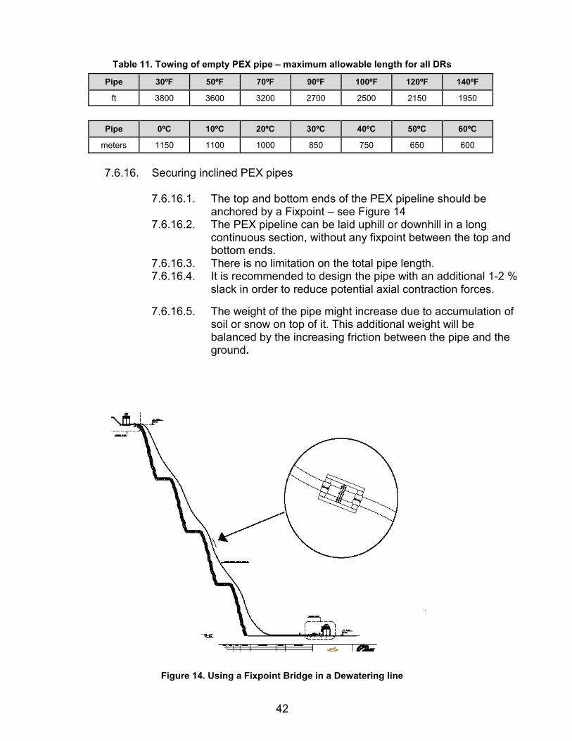
42
Table 11. Towing of empty PEX pipe – maximum allowable length for all DRs
Pipe 30ºF 50ºF 70ºF 90ºF 100ºF 120ºF 140ºF
ft 3800 3600 3200 2700 2500 2150 1950
Pipe 0ºC 10ºC 20ºC 30ºC 40ºC 50ºC 60ºC
meters 1150 1100 1000 850 750 650 600
7.6.16. Securing inclined PEX pipes
7.6.16.1. The top and bottom ends of the PEX pipeline should be
anchored by a Fixpoint – see Figure 14 7.6.16.2. The PEX pipeline can be laid uphill or downhill in a long
continuous section, without any fixpoint between the top and bottom ends.
7.6.16.3. There is no limitation on the total pipe length. 7.6.16.4. It is recommended to design the pipe with an additional 1-2 %
slack in order to reduce potential axial contraction forces.
7.6.16.5. The weight of the pipe might increase due to accumulation of soil or snow on top of it. This additional weight will be balanced by the increasing friction between the pipe and the ground.
Figure 14. Using a Fixpoint Bridge in a Dewatering line

43
7.6.17. Restraining of fittings along the pipeline
7.6.17.1. In slopes of less than 20º, all mechanical couplers (flared ends, flanged couplers etc) should be restrained by floating fixpoint devices like a fixpoint bridge. Electrofusion couplers can be installed without a floating fixpoint device.
7.6.17.2. In slopes above 20º, all type of fittings (including electrofusion couplers) should be restrained by floating fixpoint devices.
7.6.17.3. When installing a repair fitting, the pipe can be secured by a fixpoint bridge prior to cutting the pipe.
7.7. Instructions for Underground Installation of PEX Piping System For all PEX pipe DR’s, the minimum recommended depth of the trench is 23.5” (60 cm), to prevent mechanical damage to the pipe. If the pipe is to be covered only to prevent solar heating, the designer may reduce this depth. In cold areas the installation depth may be increased by the designer to prevent freezing of the transported fluids. In the case of vehicular loading, such as H-20, PEX pipes should be installed a minimum of one diameter or 18”, whichever is greater, beneath the road surface. For the maximum allowed installation depth for each pipe DR, please contact the manufacturer. Table 12 shows the minimum required trench width for PEX pipes.
Table 12. Trench width
Nominal Pipe Nominal Minimum trench Minimum trench
Size (NPS) Diameter (DN) width (inch) width (mm)
3 90 10 250 4 110 10 250 4 125 10.5 265 5 140 11 280 6 160 12 300 6 180 14 350 8 200 16 400 8 225 16 400 10 250 18 450 10 280 18 450
12 315 22 550
14 355 26 650 16 400 28 700 18 450 30 750 20 500 34 850 22 560 34 850 24 630 40 1000 28 710 44 1100 32 800 44 1100 36 900 48 1200 40 1000 52 1300

44
If required, the width can be increased to allow more comfortable work in the trench. The minimum recommended depth of the trench is 23 inches (60 cm), to prevent mechanical damage of the pipe. For a route change, for example a 90º angle, it is recommended to dig the trench with a suitable radius. 7.7.1. Backfilling of the Trench
PEX pipes generally do not require compacting, depending on the application. The excellent scratch resistance of the PEX pipes enables laying the pipes in trenches with no sand bedding – see ISO 14531-4; if sand bedding is required by the pipe designer, fill the trench with sand 4 inches (10 cm) above the pipe. Backfilling the trench using the earth originally removed from the trench is allowed, in accordance with ISO 14531Part 4; if corrosive soil is used to cover PEX pipes that are connected with metal fittings, cover the fittings with sand, not with the corrosive soil. No compacting is required for any DR of PEX pipes regardless of the depth of the trench. Installation below a road or a pavement can be done without any protective sleeves. In this case, controlled compacting of the soil/ground, according to the designer’s instructions, should be applied when covering the pipe to prevent the ground sinking. It is recommended to insulate hot water underground PEX pipes to reduce energy losses.
7.8. Above-Ground Installation Guidelines
If PEX pipe is used for above-ground applications where it is exposed to UV radiation, it must be BLACK and specifically approved by the manufacturer for the exposed application. Black PEX pipes, intended for above-ground applications, withstand exposure to sunlight for the pipe lifetime due to the absorptive properties of carbon black. Above-ground installation of black PEX pipes is advantageous in the following cases: o Slurry lines which are frequently relocated o Installation through marshes or areas with difficult access o Quick installation of temporary pipelines The coefficient of thermal expansion of PEX pipes is high compared to steel pipes, but the forces generated by thermal stresses are much lower for PEX pipes. The reason is the low modulus of elasticity and the fact that the PEX pipes feature stress relaxation. PEX pipes installed above ground might increase in length as a result of temperature increases and tend to undergo “snaking”. Longitudinal elongation and contraction of the pipe is not uniform because the coefficient of friction between the pipe and the ground varies. However, the toughness and the

45
exceptional abrasion resistance of PEX pipes enable the pipes to move across the soil without affecting strength or service life. Above ground installation instructions for PEX pipes when the design temperature is lower than the installation temperature. The pipe tends to contract longitudinally. The contraction creates axial stresses in the pipes, which tend to pullout the pipes from the fittings. Installing PEX pipes above the ground with a slack rather than in a straight line, is a way to reduce thermal stresses. This procedure reduces the tendency of the pipe to pull out of its fittings. Axially unrestrained fittings should be secured and protected from pull out.
7.8.1. Maintaining PEX pipeline on the ground in a straight line If a straight
pipeline is required, guiding the pipeline at intervals is a good method of limiting and controlling thermal expansion and contraction of the pipeline. The smaller the distance between the guides, the smaller the theoretic increase in pipe length. As a result, lateral deflections decrease and the pipeline remains straight.
7.8.2. Determining the maximum distance between two guides
The distance between two adjacent guides is calculated according to the following formula:
L = G x D Where: L is the distance (in ft or m) between the guides.
D = outside pipe diameter (in inches or mm). G is a coefficient, which depends on the temperature increase – see Table 13. ΔT between the installation temperature and the design temperature

46
The formula allows for a maximum sidewise deflection of 2" (50 mm) between two adjacent guides.
Table 13. Coefficients
ΔT (ºF) Coefficient G
- 200 18 300 13 400 9 500 7.5 700 5.4 900 4.2
1100 3.2
ΔT (ºC) Coefficient G
100 0.25 200 0.125 300 0.085 400 0.064 500 0.05 600 0.04
7.8.3. Horizontally Supported Pipeline Figures 15 and 16 on the next two pages recommend distance between supports for various SDRs and pipe diameters. The values shown in this figure must be multiplied by the following correction factors in Table 14.

47
Figure 15. Maximum Support Distance - IPS sizes

48
Figure 16. Maximum Support Distance - Metric sizes

49
Table 14. Correction factors
Design Temp. F° Correction Factor 300 1.15 500 1.11 700 1.08 800 1.04
1000 0.99 1200 0.95
14000 0.91 1600 0.87 1800 0.82 2000 0.78 2120 0.75
Design Temp. C° Correction Factor 00 1.15 100 1.11 200 1.07 300 1.03 400 0.99 500 0.95 600 0.91 700 0.87 800 0.83 900 0.79
1000 0.75
7.8.4. Fixpoint Clamps The fixpoint clamp (FPC) is made of steel with internal gripping teeth made of 316L stainless steel. The FPC is painted with a base paint that withstands welding. The lower part of the clamp can be welded to the construction bridge (before installing the pipe) or it can be connected by screws. The distance between one pipe adjacent to the other is determined according to the width of the FPCs. Affix natural pipe bends with fixpoint clamps before and after each elbow. For pipe diameters of 10” (250 mm) and larger, support the natural pipe bends in the center in addition to the two fix points noted.
7.8.5. PEX pipe behavior at high temperature
PEX pipes have a tendency to elongate considerably when exposed to sunlight due to a high thermal expansion coefficient, which is typical for plastic pipes. With increasing temperatures, the elastic modulus of the pipe decreases so the developing stress is not high. When placing PEX pipe over pipe bridges, the thermal expansion is reduced by the use of suitable fixtures so that the pipe will develop internal stresses, which do not cause any damage. There is no need to use expansion joints!

50
7.8.6. PEX pipe behavior at low temperature When the ambient temperature drops below 68ºF (20ºC), the tendency for axial contraction could create axial stresses in the pipe. The pipe absorbs these stresses without causing damage (stress relaxation). Minimum service temperature is -58ºF (-50ºC).
7.8.7. Determining the maximum force at the Fixpoint clamp
Pipes in Above- ground installations are subjected to temperature variations, which induce axial thermal movements: contraction or elongation. These axial thermal movements are partially balanced by external friction between the pipe and the construction. If a pipe is restrained with Fixpoints, they will tend to restrain these thermal movements. As a result, these Fixpoints will be subjected to axial forces, which are balanced by axial thermal stresses inside the pipe's wall. The axial thermal stresses can be calculated by the following formula:
Sigma = ExAxΔT
Where: E is the relevant (short term or long term) Modulus of Elasticity.
A is the coefficient of thermal expansion or contraction ΔT is the temperature difference.
The values of the Modulus of Elasticity and the values of the coefficient of thermal expansion or contraction are temperature dependent and so are the values of the axial thermal stresses. The highest values of the thermal stresses occur during the relatively short stage of temperature changes and therefore they involve the short-term Modulus of Elasticity. These initial short-term thermal stresses in the pipe decrease with time due to stress relaxation. These long-term stresses are usually low and therefore are of no concern for the pipe itself.
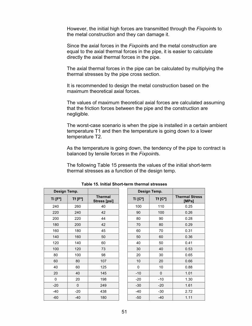
51
However, the initial high forces are transmitted through the Fixpoints to the metal construction and they can damage it. Since the axial forces in the Fixpoints and the metal construction are equal to the axial thermal forces in the pipe, it is easier to calculate directly the axial thermal forces in the pipe. The axial thermal forces in the pipe can be calculated by multiplying the thermal stresses by the pipe cross section. It is recommended to design the metal construction based on the maximum theoretical axial forces. The values of maximum theoretical axial forces are calculated assuming that the friction forces between the pipe and the construction are negligible. The worst-case scenario is when the pipe is installed in a certain ambient temperature T1 and then the temperature is going down to a lower temperature T2. As the temperature is going down, the tendency of the pipe to contract is balanced by tensile forces in the Fixpoints. The following Table 15 presents the values of the initial short-term thermal stresses as a function of the design temp.
Table 15. Initial Short-term thermal stresses Design Temp. Design Temp.
Ti [Fº] Tf [Fº] Thermal Stress [psi] Ti [Cº] Tf [Cº] Thermal Stress
[MPa] 240 260 40 100 110 0.25 220 240 42 90 100 0.26 200 220 44 80 90 0.28 180 200 42 70 80 0.29 160 180 45 60 70 0.31 140 160 50 50 60 0.36 120 140 60 40 50 0.41 100 120 73 30 40 0.53 80 100 98 20 30 0.65 60 80 107 10 20 0.66 40 60 125 0 10 0.88 20 40 145 -10 0 1.01 0 20 198 -20 -10 1.30
-20 0 249 -30 -20 1.61 -40 -20 438 -40 -30 2.72 -60 -40 180 -50 -40 1.11

52
These values are valid for a temperature difference of 20ºF or 10ºC. The following calculation example illustrates the way to calculate the axial forces in the Fixpoints. 7.8.7.1. A PEX pipe OD 280mm Wall thickness 25.4mm DR 11 was
installed in an ambient temperature of 104ºF. The design temperature in this case is 104 +36 =140ºF. In winter the temperature drops down to -20ºF. The design temperature in this case is -20 ºF The axial forces in the Fixpoints are calculated by adding the values of the thermal stresses for the temperature range between + 140ºF to -20ºF, and then multiply them by the cross section of the pipe. The sum of the values of the thermal stresses from Table 16 is 1106.76 psi:
Table 16. Sum of values
Ti [Fº] Tf [Fº] Thermal Stress [psi]
140 160 50 120 140 60 100 120 73 80 100 98 60 80 107 40 60 125 20 40 145 0 20 198
-20 0 249 Sum of the values: 1106.76
▫ The cross section of the pipe can be easily calculated
from the formula A= 3.14 x (D-T) xT ▫ For OD 280mm Wall thickness 25.4mm the pipe cross
section is 3.14 x254.6 x25.4= 20,306 mm^2. ▫ 20,306/25.4^2 = 31.48 in^2 ▫ The axial forces in the Fixpoints: ▫ 31.48x1106.76 =34834 lbs.

53
7.8.7.2. A PEX pipe OD 280mm Wall thickness 25.4mm SDR 11 was installed in an ambient temp. of 40ºC. The design temperature in this case is 40 + 20 = 60ºC In winter the temperature drops down to -30ºC. The design temperature in this case is -30ºC The axial forces in the Fixpoints are calculated by adding the values of the thermal stresses for the temperature range between + 60ºC to -30ºC, and then multiply them by the cross section of the pipe. The sum of the values of the thermal stresses from Table 17 is 7.72 MPa:
Table 17. Sum of values
Ti [Cº] Tf [Cº] Thermal Stress [MPa]
60 70 0.31 50 60 0.36 40 50 0.41 30 40 0.53 20 30 0.65 10 20 0.66 0 10 0.88
-10 0 1.01 -20 -10 1.30 -30 -20 1.61 Sum of the values: 7.72
The cross section of the pipe can be easily calculated from the formula A = 3.14 x (D-T) x T For OD 280mm Wall thickness 25.4mm the pipe cross section is 3.14 x 254.6 x 25.4= 20,306 mm2 The axial forces in the Fixpoints: 20,306 x 7.72 = 156762 N = 15.67 ton
7.8.8. Side deflection
Large side deflection might be expected in the event of a malfunction, but there is no risk of possible damage due to one pipe “leaning” on its neighbor or rubbing against it.

54
7.8.9. Guiding clamps for PEX pipes PEX pipe’s tendency to “snake” is reduced by putting bars on both sides of the pipe to limit sideward deflection. Alternatively, using guiding clamps (GC), which are conventional clamps (FPC) without the internal gripping teeth, is recommended. The pipe can freely slide through in the axial direction but not sideways.
7.8.10. Fix point bridge To ensure the pull-out resistance of certain fittings, do not lay the pipe perfectly straight, but rather with some surplus length (slack). In case of short pipes (up to about 33 ft or10 meters), or in case of installations on pipe bridges (where it might be difficult to leave slack in the pipe), there should be a Pull-out protection device such as a fixpoint clamp before and after every fitting. This applies to some of the fittings; depending on the application. If the pipe is installed in an inclined or a vertical position (for example – in dewatering applications) and common fixpoint clamps cannot be used, the fitting should be protected by a floating fixpoint device such as a fixpoint bridge.
7.8.11. Natural Bend Radius in PEX Pipes To create turns with PEX pipes laid inside trenches, above the ground or over pipe bridges, the pipe can be bent according to the manufacturer’s recommendations. Minimum bending radius recommended for each OD and SDR is available from the pipe manufacturer. PEX pipe is generally supplied in either straight lengths or coils.
Field bending involves excavating the trench to the appropriate bend radius, then sweeping or pulling the pipe string into the required bend and placing it in the trench. This kind of pipeline design, which takes advantage of the natural flexibility of the pipe, reduces the number of connections and lowers head losses. Observe appropriate safety precautions during field bending. Considerable force might be required to field bend the pipe, and the pipe could spring back forcibly if the restraints slip or are inadvertently released while bending. Consult with the PPI PEX Plumbing DESIGN GUIDE or the pipe manufacturer for the minimum bend radius.
7.8.12. Designing PEX pipes with natural bends
When designing PEX pipes with natural bends, it is recommended to consult with the manufacturer. Take into consideration that to bend the pipe on site, suitable facilities are required. Take into consideration the space required to insert the pipe into the construction, as well as the possibility to exert bending moment of the pipe.

55
7.8.13. “NATURAL” bends of PEX pipes If possible, design the pipeline with larger bending radii to facilitate pipe bending on site. The pipe bends must be fixed with fixpoint clamps before and after each elbow. For pipe diameters of 10” (280 mm) and larger, the pipe bends must be supported in the center in addition to the two fix points noted. For additional details please contact the pipe manufacturer.
7.8.14. Route change of PEX pipes inside trenches For a route change in buried pipes, it is recommended to dig the trench with the minimum natural bending radius recommended by the manufacturer.
7.8.15. Natural Bends in PEX Pipes
When designing and installing PEX pipes in natural bends, take special care to prevent excessive bending moment from being exerted on the end-connectors due to forced installation. This is relevant for both mechanical and electrofusion fittings.
7.8.16. Bending the Pipes
Use a suitable device, such as a winch or a lever, to bend the pipes. Remember that the pipe is rigid and considerable force is required for bending and fixing it – for example, 4400 lbs (2000 kg) for a 4” (110 mm) pipe and 11,000 lbs (5000 kg) for a 10” (280 mm) pipe. Please exercise caution! Bend the pipe carefully to avoid kinking. For best results, it is recommended to prepare a continuous support (with the radius of the pipe to be bent) for the pipe. Then bend the pipe against it. The installation is complicated since it is difficult to calculate in advance the exact length of the pipe. As a result, on-site adaptation (field welding) is necessary.
7.8.17. Proper installation procedure:
7.8.17.1. The longer arm of the natural bend is more flexible than the
shorter arm; therefore, always choose the longer arm as the pipe end whose length is adjusted.
7.8.17.2. Install the fitting onto the end of the shorter arm. 7.8.17.3. Connect the shorter arm to the existing counter-flange. 7.8.17.4. If necessary, install a fixpoint clamp before the fitting to
protect it during bending. ▫ If the fitting is an electrofusion fitting, wait three cooling
times (3x) before continuing with the next step. 7.8.17.5. Adjust the length of the longer arm.

56
7.8.17.6. Cut the length and install the fitting. ▫ If the fitting is an electrofusion fitting with a stub-end
(flared end) connection, perform the welding when the flared end is free (not connected to the counter-flange). Connect the flared end & flange to the counter-flange only after waiting three cooling times (3x).
▫ If the fitting is an electrofusion fitting which connects the longer arm to another PEX or PE pipe, install a temporary fixpoint bridge before welding in order to protect the electrofusion fitting during welding. Disassemble the temporary fixpoint bridge only after waiting three cooling times (3x).
8.0 PEX FITTINGS
In this section, a variety of mechanical and electrofusion fittings for PEX pipe are described. The user should confirm with the manufacturer that their PEX pipe is suitable for joining with electrofusion fittings. The fittings shown are examples only, and other suitable fittings can be used. Fittings are available for PEX pipe in metric pipe sizes (20 mm to 710 mm). Fittings are also available from various manufacturers for PEX pipe in inch pipe sizes (3” to 54”). Generally all types of mechanical fittings which are suitable for PE pipes can be used for PEX pipes. Refer to the fitting manufacturer for suitability of use with PEX pipe in the intended application. 8.1. PE100 Electrofusion fittings
Electrofusion fittings made from PE 4710 (or PE 100) material (for example, ASTM F1055) are used to connect PEX pipes (for example, ASTM F2788 or ISO 14531). The pipes and fittings are joined by electrofusion welding, creating a leak-proof seal. During the electrofusion process, electrical energy is applied to the fitting, heat is produced that melts and joins the pipe and fitting. The surrounding material (around the wire) is melted, welding the pipe to the fitting. Refer to the electrofusion fitting manufacturer for suitability of use with PEX pipe in the intended application.
Note: Some PEX pipes cannot be joined by the electrofusion joining process. Consult with the PEX pipe manufacturer to determine suitability of the PEX pipe for electrofusion joining.
The service temperature for the PE 100 electrofusion fittings is limited to 140ºF (60ºC). For higher temperatures, electrofusion fittings made from PEX or PERT should be used. There are a variety of PE 100 electrofusion fittings, PEX electrofusion fittings and electrofusion control boxes, as shown on the next page, which are available to join PEX pipe

57
8.1.1. Instruction for Welding Electrofusion Fittings PE /PEX electrofusion fittings can be used to connect PEX pipes in the same way as PE pipes. Electrofusion fittings are the main means of connection in municipal
water and industrial distribution systems. Fittings are tested and have a lifetime of 50 years. Lightweight and small volume welding connectors. Economical use especially for large diameters in water
transportation. Connectors are offered in diameters ranging from 3" to 32 " (75 mm
to 800 mm) as well as in a wide variety of fittings: couplers, elbows, end plugs, tees, saddles, tapping saddles (for connecting new outlets to “live line”).
The entire electrofusion process is executed and fully monitored by the computerized control box ensuring safe, reliable connections.
8.1.2. Installation instructions for electrofusion fittings:
Installation is performed only by trained workers who have been certified showing that they have been trained by a person authorized by the PEX pipe manufacturer.
8.1.3. Type of electrofusion fittings:
Some PEX pipes are more difficult to fuse than others. Therefore you should use only electrofusion fittings, which were tested and approved by the fitting producer for fusion with the specific PEX pipe. See fitting manufacturer for any pipe size limitations.
8.1.4. Rounding the pipe
For a quality fusion and for easy insertion, rounding the pipe is compulsory. This is achieved by using rounding tools, which are placed on the pipe end. The tools maintain a rounded pipe during the welding process. Support of the fitting during the welding process: When welding pipes in diameters 3” (90 mm) and higher, the pipe should be inserted into the fitting by means of spanners (come-alongs) that allow controlled insertion and ensure the coupler does not move during the welding process.

58
Cooling time: Please note the cooling time that appears on a sticker on each fitting. Do not disassemble spanners and rounding devices until the cooling time has elapsed.
A good practice: When the fusion process is completed, note the hour and add the cooling time. The result is the disassemble time. Mark this time on the fitting and do not disassemble it earlier than this time! PE electrofusion fittings, made from PE 4710, are allowed for use at the pressures and temperatures as shown in Tables 18 and 19, based on an HDB of 1600 psi and a design factor of 0.63:
Table 18. Working Pressures (psig)
Temperature (F) Working pressure (PSI)
68.0 232.0 77.0 208.8 86.0 188.5 95.0 166.75
104.0 143.55 113.0 120.35 122.0 100.0
Table 19. Working Pressures (bar)
Temperature (C) Working pressure (Bar)
20 16.0 25 14.4 30 13.0 35 11.5 40 9.9 45 8.3 50 6.9
8.2. PEX-Lined Fittings
PEX-lined steel fittings consist of a steel flanged fitting lined with thick black PEX coating, which extends over the full face of the flanges. This type of fitting can be used as a standard fitting such as a Tee, an elbow, or a reducer. The design of the fittings is based on ASME B16.5. The fittings are supplied with an external epoxy coating. Standard fittings are usually supplied with wall thickness of PEX layer: 3–5 mm for corrosion resistance and up to 10 mm for abrasion resistance. The fittings

59
are usually supplied with weld-neck flanges. The minimum length of each fitting is generally indicated in the manufacturer’s fitting catalogue. 8.2.1. Branch Saddles
Branch saddles are designed for side outlets of a maximum diameter equaling half of the main pipe’s diameter. They are made from plastic or metal. Recommended installation for the plastics saddles is in the ground. If you must install metal saddles in the ground, make sure the ground is not corrosive for brass or stainless steel saddles. Do not connect brass fittings to steel or galvanized steel pipes or fittings. PEX pipes can be used with plastic saddles such as mechanical saddles or electrofusion saddles, with restrictions regarding the allowable temperature and pressure range, according to the pipe manufacturer’s recommendations for PEX pipe connections. Metal saddles are suitable for the full temperature and pressure ranges of PEX pipes. Brass saddles with threaded outlets are used for pipes from 32 mm to 160 mm diameter; see the next page for the installation of saddles.
8.2.2. Installation Instructions for Saddles
Note the following data for installing brass saddles, electrofusion saddles and stainless steel saddles to PEX pipes.
Note: Install all saddles onto the pipe prior to drilling the outlet hole.
8.2.3. Prefabricated PEX Sweep Elbows Prefabricated sweep elbows of various angles and radii are produced from PEX pipes of all DR’s. Prefabricated elbows with flared-ends are available.
8.3. Flared End Connectors The ends of the PEX pipe are heated and then flared. The final pipe end is similar to a stub end. Flared ends can be also be made at the ends of PEX elbows, reducers, etc. The loose flange is usually mounted over the pipe during the flaring process. Alternatively, split flanges can be mounted later. 8.3.1. Connecting PEX Pipes with Flared Ends
The flared-end connection is suitable for both hot and cold media. Special fixpoint clamps should be used before and after the flared ends. Flange material is carbon steel A37. Other carbon steel or stainless steel grades can be ordered. In case of subzero temperatures, special restraining
60
techniques should be employed to prevent pulling out of the flared end from the flanges. No gasket is needed when connecting two PEX pipes with flared ends and flanges or when connecting a PEX pipe with a flared end to a flanged fitting. Tighten the bolts evenly around the flange until all the bolts are all tight. Tighten the bolts evenly using 75% of the recommended torque values and then tighten to the final value. No re-torquing is necessary in the flared ends of PEX pipes.
8.3.2. PEX Spigot Reducers PEX concentric spigot reducers are available. The working pressures and temperatures of the PEX spigot reducers are the same as for the d1 side of the reducer. When using the Spigot reducers to connect them with electrofusion couplers, the end user can shorten the lengths.
8.3.3. PEX Reducers with Flared Ends and Flanges The working pressures and temperatures of the PEX spigot reducers are the same as for the d1 side of the reducer.
8.3.4. Flanged Coupling for PEX Pipes Flanged couplings are available in standard sizes.
8.4. Brass Fittings for PEX Pipes
It is recommended to install brass fittings above the ground. If you must install brass fittings in the ground, make sure they are protected from corrosion. Do not connect brass fittings to steel or galvanized steel pipes or fittings.
8.5. Design Considerations for PEX Fittings
8.5.1. Elbows 8.5.1.1. Where possible, use PEX straight pipes with a natural bend.
Always select the length of the two sections so that the electrofusion coupler is not in the exact location of the bend.
8.5.1.2. When straight pipe sections with the natural bend are not an option, use prefabricated PEX elbows 3XD or 1.5XD.
8.5.1.3. Note that 1.5XD elbows are significantly longer than the carbon steel 1.5xD elbows.
8.5.1.4. 3XD elbows are recommended rather than 1.5XD since 3XD elbows reduce head losses and abrasion rate.
8.5.2. PEX-lined steel fittings
Components in the line that are not straight pipes or elbows including steel tees, laterals, and others can be designed as PEX-lined steel fittings. However, if you find that you need to make a non-standard item

61
with longer or shorter legs, make your selection and ask the manufacturer for approval. The standard items come with fixed flanges. For each end, select whether the flange is a fixed flange or a loose flange. Elbows and natural pipe bends must be fixed with fixpoint clamps before and after each elbow. For pipe diameters of 11 inches (280 mm) and larger, the natural pipe bends should be supported in the center, in addition to the two fixpoints.
8.5.3. E.3. Expansion joints & Omega loops:
Expansion joints and Omega loops are not necessary in a PEX system. However, expansion joints might be needed when connecting a few PEX-lined steel fittings.
8.5.4. Influence of temperature changes on pipeline length
8.5.4.1. The length of PEX pipes can be increased by 0.3% for a temperature increase of 36ºF (20ºC), meaning 0.12 inch (3 mm) for every 3 ft (1 meter).
8.5.4.2. When installing a straight PEX pipe section between two steel
flanges, specify the length of the PEX pipe section 0.2 – 0.4 inches (5–10 mm) shorter than the length between two steel flanges. This allows easy installation, and takes into consideration the thermal expansion of the PEX pipe.
8.5.5. Field welding
8.5.5.1. Allow ”field welds” in order to compensate the deviation of the
actual length of the pipe during the installation from the designed length. In most cases, these field welds are done with electrofusion couplers or mechanical couplers, so other methods are not necessary.
8.5.5.2. When using only mechanical connectors, design some of them so that the final pipe length can be adjusted on site.
8.5.6. Protecting the fittings
8.5.6.1. When designing PEX pipes and fittings, the designer can utilize the flexibility of the PEX pipes & elbows. However, electrofusion and mechanical fittings should be regarded as rigid items.
8.5.6.2. Special care should be exercised in order to prevent
excessive bending moment from being exerted on the fittings due to forced installation.
62
8.5.7. Fixpoints
Fixpoints must be designed before and after each fitting (for example, flared end connection) as specified in the manufacturer’s engineering guide.
8.5.8. Specifying the length of the PEX straight sections and elbows as
separate items is acceptable after the design has been completed and approved by the manufacturer. It is a good practice to specify a longer section to allow for measuring inaccuracies other possible errors.
9.0 PRESSURE TESTS
Performing Pressure Tests in PEX Water Supply Lines and Dewatering 9.1. Test purpose:
Final check to make sure there are no leakages in the fittings.
9.2. Test procedure:
9.2.1. Make sure the underground pipes are already covered, leaving only the
fittings uncovered It is recommended to fill up the pipeline with water at the maximum working pressure on the day before the test
9.2.2. On the day of the test, inspect the pipeline visually, especially around the fittings.
9.3. Temporarily cover metal fittings (flanged couplings, branch-off saddles) to prevent
excessive heat buildup due to exposure to sunlight.
9.3.1. For installation above the ground, use test pressures in the Tables 18 and 19. Take into consideration that the pipe might be heated due to exposure to sunlight.
9.3.2. Take into consideration changes in the pipeline topography (which could create higher local pressure due to a water column); reduce the test pressure accordingly.
9.4. Pressure testing – see Tables 20 and 21:
9.4.1. Bring the pressure to the level of the test pressure (see table below) and
then close the feeding line. 9.4.2. As the pipe is flexible and tends to expand its diameter under pressure,
the line pressure is expected to decrease. 9.4.3. Increase the line pressure again, up to the test pressure. 9.4.4. With each cycle of pressure reduction and increase, the pressure is
expected to decrease less.

63
9.5. After 3-4 cycles, rapidly lower the pressure to 75% of the working pressure by letting water out of the line.
9.5.1. After closing the valve, the pressure is expected to increase as a result of
the tendency of the pipe to decrease its volume. 9.5.2. If the pressure decreases instead of increasing, investigate the reason for
pressure loss, for example, leakages at the fittings.
Table 20. Pressure test – psig
Test pressure – PSI
Pipe class
Above ground inst. Underground inst.
Ambient Temp. (°F) Fluid Temp. (°F)
104.0 86.0 68.0 104.0 86.0 68.0
58.0 72.5 79.8 79.8 87.0 101.5 6
79.8 87.0 101.5 101.5 108.8 130.5 8
101.5 116.0 130.5 130.5 145.0 174.0 10 123.3 145.0 159.5 159.5 181.3 203.0 12 159.5 181.3 203.0 203.0 224.8 261.0 15 203.0 224.8 253.8 253.8 290.0 319.0 19 246.5 290.0 319.0 319.0 362.5 420.5 24 319.0 362.5 406.0 406.0 456.8 507.5 30
Table 21. Pressure test – bar
Test pressure – bar Pipe class
Above ground inst. Underground inst.
Ambient Temp. (°C) Fluid Temp. (°C) 40.0 30.0 20.0 40.0 30.0 20.0
4 5 5.5 5.5 6 7 6
5.5 6 7 7 7.5 9 8
7 8 9 9 10 12 10 8.5 10 11 11 12.5 14 12 11 12.5 14 14 15.5 18 15 14 15.5 17.5 17.5 20 22 19 17 20 22 22 25 29 24
10.0 PEX CHEMICAL RESISTANCE
PPI TR-19 “Chemical Resistance of Thermoplastic Piping Materials” can be used as a general guidance for chemical resistance of PEX pipe. For more specific information please contact the PEX pipe manufacturer.
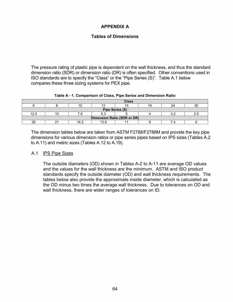
64
APPENDIX A
Tables of Dimensions
The pressure rating of plastic pipe is dependent on the wall thickness, and thus the standard dimension ratio (SDR) or dimension ratio (DR) is often specified. Other conventions used in ISO standards are to specify the “Class” or the “Pipe Series (S)”. Table A.1 below compares these three sizing systems for PEX pipe.
Table A - 1. Comparison of Class, Pipe Series and Dimension Ratio
Class 6 8 10 12 15 19 24 30
Pipe Series (S) 12.5 10 7.6 6.3 5 4 3.2 2.5
Dimension Ratio (SDR or DR) 26 21 16.2 13.6 11 9 7.4 6 The dimension tables below are taken from ASTM F2788/F2788M and provide the key pipe dimensions for various dimension ratios or pipe series pipes based on IPS sizes (Tables A.2 to A.11) and metric sizes (Tables A.12 to A.19).
A.1 IPS Pipe Sizes
The outside diameters (OD) shown in Tables A-2 to A-11 are average OD values and the values for the wall thickness are the minimum. ASTM and ISO product standards specify the outside diameter (OD) and wall thickness requirements. The tables below also provide the approximate inside diameter, which is calculated as the OD minus two times the average wall thickness. Due to tolerances on OD and wall thickness, there are wider ranges of tolerances on ID.

65
Table A - 2. PEX IPS Pipe Properties – DR 26
Nominal Pipe Size (NPS)
O.D Inch
Wall thickness Inch
I.D Inch Weight lb/ft
3 3.50 0.13 3.23 0.62 4 4.50 0.17 4.15 1.02 5 5.56 0.21 5.14 1.56 6 6.63 0.25 6.12 2.21 8 8.63 0.33 7.96 3.74
10 10.75 0.41 9.92 5.82 12 12.75 0.49 11.77 8.18 14 14.00 0.54 12.92 9.86 16 16.00 0.62 14.77 12.88 18 18.00 0.69 16.62 16.31 20 20.00 0.77 18.46 20.13 22 22.00 0.85 20.31 24.36 24 24.00 0.92 22.15 28.99 26 26.00 1.00 24.00 34.02 28 28.00 1.08 25.85 39.46 30 30.00 1.15 27.69 45.29 32 32.00 1.23 29.54 51.53 34 34.00 1.31 31.38 58.18 36 36.00 1.38 33.23 65.22 42 42.00 1.62 38.77 88.77 48 48.00 1.85 44.31 115.95 54 54.00 2.08 49.85 146.75
Table A - 3. PEX IPS Pipe Properties – SDR 21
Nominal Pipe Size (NPS)
O.D Inch
Wall thickness Inch
I.D Inch Weight lb/ft
3 3.50 0.17 3.17 0.76 4 4.50 0.21 4.07 1.25 5 5.56 0.27 5.03 1.91 6 6.63 0.32 6.00 2.70 8 8.63 0.41 7.80 4.59
10 10.75 0.51 9.73 7.13 12 12.75 0.61 11.54 10.03 14 14.00 0.67 12.67 12.10 16 16.00 0.76 14.48 15.80 18 18.00 0.86 16.29 19.99 20 20.00 0.95 18.10 24.68 22 22.00 1.05 19.90 29.88 24 24.00 1.14 21.71 35.55 26 26.00 1.24 23.52 41.72 28 28.00 1.33 25.33 48.37 30 30.00 1.43 27.14 55.56 32 32.00 1.52 28.95 63.20 34 34.00 1.62 30.76 71.34 36 36.00 1.71 32.57 79.97 42 42.00 2.00 38.00 108.86 48 48.00 2.29 43.43 142.21 54 54.00 2.57 48.86 179.93

66
Table A - 4. PEX IPS Pipe Properties – SDR 17
Nominal Pipe Size (NPS)
O.D Inch
Wall thickness
I.D Inch
Weight lb/ft
3 3.50 0.21 3.09 0.92 4 4.50 0.27 3.97 1.53 5 5.56 0.33 4.91 2.33 6 6.63 0.39 5.85 3.31 8 8.63 0.51 7.61 5.60 10 10.75 0.63 9.49 8.70 12 12.75 0.75 11.25 12.25 14 14.00 0.82 12.35 14.77 16 16.00 0.94 14.12 19.28 18 18.00 1.06 15.88 24.41 20 20.00 1.18 17.65 30.12 22 22.00 1.29 19.41 36.46 24 24.00 1.41 21.18 43.40 26 26.00 1.53 22.94 50.92 28 28.00 1.65 24.71 59.06 30 30.00 1.77 26.47 67.82 32 32.00 1.88 28.24 77.13 34 34.00 2.00 30.00 87.09 36 36.00 2.12 31.76 97.65 42 42.00 2.47 37.06 132.92 48 48.00 2.82 42.35 173.61 54 54.00 3.18 47.65 219.66
Table A - 5. PEX IPS Pipe Properties – DR 15.5
Nominal Pipe Size (NPS)
O.D Inch
Wall thickness Inch
I.D Inch
Weight lb/ft
3 3.50 0.21 3.09 0.92 4 4.50 0.27 3.97 1.53 5 5.56 0.33 4.91 2.33 6 6.63 0.39 5.85 3.31 8 8.63 0.51 7.61 5.60
10 10.75 0.63 9.49 8.70 12 12.75 0.75 11.25 12.25 14 14.00 0.82 12.35 14.77 16 16.00 0.94 14.12 19.28 18 18.00 1.06 15.88 24.41 20 20.00 1.18 17.65 30.12 22 22.00 1.29 19.41 36.46 24 24.00 1.41 21.18 43.40 26 26.00 1.53 22.94 50.92 28 28.00 1.65 24.71 59.06 30 30.00 1.77 26.47 67.82 32 32.00 1.88 28.24 77.13 34 34.00 2.00 30.00 87.09 36 36.00 2.12 31.76 97.65 42 42.00 2.47 37.06 132.92 48 48.00 2.82 42.35 173.61

67
Table A - 6. PEX IPS Pipe Properties – SDR 13.5
Nominal Pipe Size (NPS)
O.D Inch
Wall thickness Inch I.D Inch Weight
lb/ft 3 3.50 0.26 2.98 1.14 4 4.50 0.33 3.83 1.89 5 5.56 0.41 4.74 2.89 6 6.63 0.49 5.64 4.10 8 8.63 0.64 7.35 6.94
10 10.75 0.80 9.16 10.78 12 12.75 0.94 10.86 15.17 14 14.00 1.04 11.93 18.29 16 16.00 1.19 13.63 23.89 18 18.00 1.33 15.33 30.23 20 20.00 1.48 17.04 37.32 22 22.00 1.63 18.74 45.18 24 24.00 1.78 20.44 53.77 26 26.00 1.93 22.15 63.10 28 28.00 2.07 23.85 73.17 30 30.00 2.22 25.56 83.99 32 32.00 2.37 27.26 95.56 34 34.00 2.52 28.96 107.91 36 36.00 2.67 30.67 120.97
Table A - 7. PEX IPS Pipe Properties – SDR 11
Nominal Pipe Size (NPS)
O.D Inch
Wall thickness Inch
I.D Inch
Weight lb/ft
3 3.50 0.32 2.86 1.38 4 4.50 0.41 3.68 2.28 5 5.56 0.51 4.55 3.48 6 6.63 0.60 5.42 4.93 8 8.63 0.78 7.06 8.37 10 10.75 0.98 8.80 12.99 12 12.75 1.16 10.43 18.28 14 14.00 1.27 11.45 22.05 16 16.00 1.46 13.09 28.80 18 18.00 1.64 14.73 36.43 20 20.00 1.82 16.36 44.98 22 22.00 2.00 18.00 54.43 24 24.00 2.18 19.64 64.78 26 26.00 2.36 21.27 76.04 28 28.00 2.55 22.91 88.16 30 30.00 2.73 24.55 101.21 32 32.00 2.91 26.18 115.16 34 34.00 3.09 27.82 130.01 36 36.00 3.27 29.45 145.76

68
Table A - 8. PEX IPS Pipe Properties – SDR 9
Nominal Pipe Size
(NPS)
O.D Inch
Wall thickness Inch
I.D Inch
Weight lb/ft
3 3.50 0.39 2.72 1.65 4 4.50 0.50 3.50 2.72 5 5.56 0.62 4.33 4.16 6 6.63 0.74 5.15 5.90 8 8.63 0.96 6.71 10.00
10 10.75 1.19 8.36 15.53 12 12.75 1.42 9.92 21.85 14 14.00 1.56 10.89 26.35 16 16.00 1.78 12.44 34.41 18 18.00 2.00 14.00 43.55 20 20.00 2.22 15.56 53.76 22 22.00 2.44 17.11 65.04 24 24.00 2.67 18.67 77.42 26 26.00 2.89 20.22 90.88
Table A - 9. PEX IPS Pipe Properties – DR 8.3
Nominal Pipe Size
(NPS)
O.D Inch
Wall thickness Inch
I.D Inch
Weight lb/ft
3 3.50 0.42 2.66 1.77 4 4.50 0.54 3.42 2.92 5 5.56 0.67 4.22 4.46 6 6.63 0.80 5.03 6.33 8 8.63 1.04 6.55 10.73 10 10.75 1.30 8.16 16.66 12 12.75 1.54 9.68 23.44 14 14.00 1.69 10.63 28.27 16 16.00 1.93 12.14 36.92 18 18.00 2.17 13.66 46.73 20 20.00 2.41 15.18 57.67 22 22.00 2.65 16.70 69.78 24 24.00 2.89 18.22 83.02 26 26.00 3.13 19.74 97.41

69
Table A - 10. PEX IPS Pipe Properties – DR 7.3
Nominal Pipe Size
(NPS)
O.D Inch
Wall thickness Inch
I.D Inch
Weight lb/ft
3 3.50 0.48 2.54 1.97 4 4.50 0.62 3.27 3.26 5 5.56 0.76 4.04 4.98 6 6.63 0.91 4.81 7.06 8 8.63 1.18 6.26 11.97 10 10.75 1.47 7.80 18.60 12 12.75 1.75 9.26 26.16 14 14.00 1.92 10.16 31.53 16 16.00 2.19 11.62 41.19 18 18.00 2.47 13.07 52.13 20 20.00 2.74 14.52 64.36 22 22.00 3.00 16.00 77.57 24 24.00 3.29 17.42 92.72 26 26.00 3.56 18.88 108.71
Table A - 11. PEX IPS Pipe Properties – DR 6
Nominal Pipe Size
(NPS)
O.D Inch
Wall thickness Inch
I.D Inch
Weight lb/ft
3 3.50 0.58 2.33 2.32 4 4.50 0.75 3.00 3.83 5 5.56 0.93 3.71 5.85 6 6.63 1.1 4.42 8.30 8 8.63 1.44 5.75 14.06 10 10.75 1.79 7.17 21.84 12 12.75 2.13 8.50 30.72 14 14.00 2.33 9.33 37.04 16 16.00 2.67 10.67 48.38 18 18.00 3 12.00 61.24 20 20.00 3.33 13.33 75.60 22 22.00 3.67 14.67 91.48 24 24.00 4 16.00 108.86 26 26.00 4.33 17.33 127.76

70
A.2 Metric Pipe Sizes
Tables A.12 to A.19 are taken from ASTM F2788/F2788 M and refer to different nominally dimensioned PEX pipes based on the SI system. The outside diameters (OD) and wall thickness values shown are the minimum values.
Table A - 12. PEX PIPE Properties – SDR 26 (Series 12.5)
Diameter Nominal
(DN)
O.D mm
Wall thickness mm I.D. mm I.D Inch Weight kg/m Weight
lb/ft
90 90.00 3.50 83.00 3.27 0.90 0.60 110 110.00 4.20 101.60 4.00 1.40 0.94 125 125.00 4.80 115.40 4.54 1.80 1.21 140 140.00 5.40 129.20 5.09 2.30 1.55 160 160.00 6.20 147.60 5.81 3.00 2.02 180 180.00 6.90 166.20 6.54 3.70 2.49 200 200.00 7.70 184.60 7.27 4.60 3.09 225 225.00 8.60 207.80 8.18 5.80 3.90 250 250.00 9.60 230.80 9.09 7.20 4.84 280 280.00 10.70 258.60 10.18 9.00 6.05 315 315.00 12.10 290.80 11.45 11.40 7.66 355 355.00 13.60 327.80 12.91 14.40 9.68 400 400.00 15.30 369.40 14.54 18.30 12.30 450 450.00 17.20 415.60 16.36 23.20 15.59 500 500.00 19.10 461.80 18.18 28.60 19.22 560 560.00 21.40 517.20 20.36 35.80 24.06 630 630.00 24.10 581.80 22.91 45.40 30.51 710 710.00 27.20 655.60 25.81 57.80 38.84 800 800.00 30.70 738.60 29.08 73.40 49.33 900 900.00 34.60 830.80 32.71 93.10 62.57
1,000 1,000.00 38.40 923.20 36.35 115.00 77.29

71
Table A - 13. PEX PIPE Properties – SDR 21 (Series 10)
Diameter Nominal
(DN)
O.D mm
Wall thickness mm I.D. mm I.D Inch Weight kg/m Weight
lb/ft
75 75.00 3.60 67.80 2.67 0.80 0.54 90 90.00 4.30 81.40 3.20 1.10 0.74
110 110.00 5.30 99.40 3.91 1.70 1.14 125 125.00 6.00 113.00 4.45 2.20 1.48 140 140.00 6.70 126.60 4.98 2.80 1.88 160 160.00 7.70 144.60 5.69 3.60 2.42 180 180.00 8.60 162.80 6.41 4.60 3.09 200 200.00 9.60 180.80 7.12 5.70 3.83 225 225.00 10.80 203.40 8.01 7.20 4.84 250 250.00 11.90 226.20 8.91 8.80 5.91 280 280.00 13.40 253.20 9.97 11.10 7.46 315 315.00 15.00 285.00 11.22 14.00 9.41 355 355.00 16.90 321.20 12.65 17.80 11.96 400 400.00 19.10 361.80 14.24 22.60 15.19 450 450.00 21.50 407.00 16.02 28.70 19.29 500 500.00 23.90 452.20 17.80 35.40 23.79 560 560.00 26.70 506.60 19.94 44.30 29.77 630 630.00 30.00 570.00 22.44 56.00 37.63 710 710.00 33.80 642.40 25.29 71.10 47.78 800 800.00 38.10 723.80 28.50 90.30 60.69 900 900.00 42.80 814.40 32.06 114.00 76.61
1,000 1,000.00 47.60 904.80 35.62 141.00 94.76
Table A - 14. PEX PIPE Properties – DR 16.2 (Series 7.6)
Diameter Nominal
(DN)
O.D mm
Wall thickness mm
I.D. mm I.D Inch Weight kg/m Weight
lb/ft
63 63.00 3.90 55.20 2.17 0.72 0.48 75 75.00 4.70 65.80 2.59 1.03 0.69 90 90.00 5.60 78.80 3.10 1.47 0.99
110 110.00 6.80 96.40 3.80 2.18 1.47 125 125.00 7.70 109.60 4.31 2.81 1.89 140 140.00 8.70 122.60 4.83 3.55 2.39 160 160.00 9.90 140.20 5.52 4.62 3.10 180 180.00 11.10 157.80 6.21 5.83 3.92 200 200.00 12.40 175.20 6.90 7.23 4.86 225 225.00 13.90 197.20 7.76 9.12 6.13 250 250.00 15.50 219.00 8.62 11.30 7.59 280 280.00 17.30 245.40 9.66 14.10 9.48 315 315.00 19.50 276.00 10.87 17.90 12.03 355 355.00 21.90 311.20 12.25 22.70 15.26 400 400.00 24.70 350.60 13.80 28.80 19.36 450 450.00 27.80 394.40 15.53 36.50 24.53 500 500.00 30.90 438.20 17.25 45.00 30.24 560 560.00 34.60 490.80 19.32 53.60 36.02 630 630.00 38.90 552.20 21.74 71.50 48.05 710 710.00 43.80 622.40 24.50 90.70 60.96 800 800.00 49.40 701.20 27.61 115.00 77.29 900 900.00 55.50 789.00 31.06 146.00 98.12
1,000 1,000.00 61.70 876.60 34.51 180.00 120.97

72
Table A - 15. PEX PIPE Properties – DR 13.6 (Series 6.3)
Diameter Nominal
(DN)
O.D mm
Wall thickness mm I.D. mm I.D Inch Weight kg/m Weight
lb/ft
63 63.00 4.70 53.60 2.11 0.85 0.57 75 75.00 5.60 63.80 2.51 1.21 0.81 90 90.00 6.70 76.60 3.02 1.73 1.16
110 110.00 8.10 93.80 3.69 2.57 1.73 125 125.00 9.20 106.60 4.20 3.31 2.22 140 140.00 10.30 119.40 4.70 4.15 2.79 160 160.00 11.80 136.40 5.37 5.43 3.65 180 180.00 13.30 153.40 6.04 6.80 4.57 200 200.00 14.70 170.60 6.72 8.47 5.69 225 225.00 16.60 191.80 7.55 10.70 7.19 250 250.00 18.40 213.20 8.39 13.40 9.01 280 280.00 20.60 238.80 9.40 16.60 11.16 315 315.00 23.20 268.60 10.57 21.00 14.11 355 355.00 26.10 302.80 11.92 26.70 17.94 400 400.00 29.40 341.20 13.43 33.90 22.78 450 450.00 33.10 383.80 15.11 42.90 28.83 500 500.00 36.70 426.40 16.79 52.80 35.48 560 560.00 41.20 477.60 18.80 66.50 44.69 630 630.00 46.60 537.40 21.16 84.60 56.86 710 710.00 52.20 605.60 23.84 107.00 71.91 800 800.00 58.80 682.40 26.87 135.00 90.73 900 900.00 66.20 767.60 30.22 172.00 115.59
1,000 1,000.00 73.50 865.00 34.06 212.00 142.47
Table A - 16. PEX PIPE Properties – SDR 11 (Series 5)
Diameter Nominal
(DN)
O.D mm
Wall thickness
mm I.D. mm I.D Inch Weight kg/m Weight
lb/ft
63 63.00 5.80 51.40 2.02 1.03 0.69 75 75.00 6.80 61.40 2.42 1.44 0.97 90 90.00 8.20 73.60 2.90 2.09 1.40
110 110.00 10.00 90.00 3.54 3.11 2.09 125 125.00 11.40 102.20 4.02 4.03 2.71 140 140.00 12.70 114.60 4.51 5.02 3.37 160 160.00 14.60 130.80 5.15 6.60 4.44 180 180.00 16.40 147.20 5.80 8.34 5.60 200 200.00 18.10 163.80 6.45 10.20 6.85 225 225.00 20.40 184.20 7.25 12.90 8.67 250 250.00 22.70 204.60 8.06 16.00 10.75 280 280.00 25.40 229.20 9.02 20.10 13.51 315 315.00 28.60 257.80 10.15 25.50 17.14 355 355.00 32.20 290.60 11.44 32.30 21.71 400 400.00 36.30 327.40 12.89 41.50 27.89 450 450.00 40.90 368.20 14.50 52.00 34.95 500 500.00 45.40 409.20 16.11 65.00 43.68 560 560.00 50.90 458.40 18.05 82.00 55.11 630 630.00 57.30 515.60 20.30 103.00 69.22 710 710.00 64.50 581.00 22.87 129.00 86.69 800 800.00 72.70 654.00 25.75 164.00 110.22 900 900.00 81.80 736.00 28.98 208.00 139.79
1,000 1,000.00 90.90 818.00 32.20 257.00 172.72

73
Table A - 17. PEX PIPE Properties – SDR 9 (Series 4)
Diameter Nominal
(DN)
O.D mm
Wall thickness mm I.D. mm I.D Inch Weight kg/m Weight
lb/ft
63 63.00 7.10 48.80 1.92 1.25 0.84 75 75.00 8.40 58.20 2.29 1.75 1.18 90 90.00 10.10 69.80 2.75 2.50 1.68
110 110.00 12.30 85.40 3.36 3.75 2.52 125 125.00 14.10 97.00 3.82 4.90 3.29 140 140.00 15.70 108.60 4.28 6.10 4.10 160 160.00 17.90 124.20 4.89 7.90 5.31 180 180.00 20.10 139.80 5.50 9.90 6.65 200 200.00 22.40 155.20 6.11 12.40 8.33 225 225.00 25.20 175.00 6.89 15.50 10.42 250 250.00 27.90 194.20 7.65 19.30 12.97 280 280.00 31.30 217.40 8.56 24.20 16.26 315 315.00 35.20 244.60 9.63 30.60 20.56 355 355.00 39.70 275.60 10.85 39.00 26.21 400 400.00 44.70 310.60 12.23 49.40 33.20 450 450.00 50.30 349.40 13.76 62.50 42.00 500 500.00 55.80 388.40 15.29 77.00 51.75 560 560.00 62.50 435.00 17.13 96.70 64.99 630 630.00 70.00 489.40 19.27 122.00 81.99 710 710.00 78.90 552.20 21.74 155.00 104.17 800 800.00 88.90 622.00 24.49 197.00 132.39 900 900.00 100.00 700.00 27.56 249.00 167.34
1,000 1,000.00 111.10 778.00 30.63 307.00 206.32
Table A - 18. PEX PIPE Properties – DR 7.4 (Series 3.2)
Diameter Nominal
(DN)
O.D mm
Wall thickness mm I.D. mm I.D Inch Weight kg/m Weight
lb/ft
63 63.00 8.60 45.80 1.80 1.45 0.97 75 75.00 10.30 54.40 2.14 2.07 1.39 90 90.00 12.30 65.40 2.57 2.97 2.00
110 110.00 15.10 79.80 3.14 4.45 2.99 125 125.00 17.10 90.80 3.57 5.73 3.85 140 140.00 19.20 101.60 4.00 7.21 4.85 160 160.00 21.90 116.20 4.57 9.40 6.32 180 180.00 24.60 130.80 5.15 11.90 8.00 200 200.00 27.30 145.20 5.72 14.60 9.81 225 225.00 30.80 163.40 6.43 18.60 12.50 250 250.00 34.20 181.60 7.15 23.00 15.46 280 280.00 38.30 203.40 8.01 29.00 19.49 315 315.00 43.10 228.80 9.01 37.00 24.87 355 355.00 48.50 258.00 10.16 47.00 31.59 400 400.00 54.70 290.60 11.44 59.00 39.65 450 450.00 61.50 327.00 12.87 75.00 50.40 500 500.00 68.50 363.00 14.29 93.00 62.50 560 560.00 76.70 406.50 16.00 117.00 78.63 630 630.00 86.30 457.00 17.99 148.00 99.46 710 710.00 97.30 515.00 20.28 185.00 124.33 800 800.00 108.10 584.00 22.99 232.00 155.92 900 900.00 121.60 657.00 25.87 294.00 197.58
1,000 1,000.00 135.10 730.00 28.74 363.00 243.95

74
Table A - 19. PEX PIPE Properties – DR 6 Series 2.5)
Diameter Nominal
(DN)
O.D mm
Wall thickness Mm I.D. mm I.D Inch Weight kg/m Weight
lb/ft
63.0 63.00 10.50 42.00 1.65 1.70 1.14 75.0 75.00 12.50 50.00 1.97 2.40 1.61 90.0 90.00 15.00 60.00 2.36 3.50 2.35
110.0 110.00 18.30 73.00 2.87 5.20 3.49 125.0 125.00 20.80 83.40 3.28 6.80 4.57 140.0 140.00 23.30 93.00 3.66 8.50 5.71 160.0 160.00 26.60 106.80 4.20 11.00 7.39 180.0 180.00 29.90 120.00 4.72 14.00 9.41 200.0 200.00 33.20 133.50 5.26 17.20 11.56 225.0 225.00 37.40 150.00 5.91 22.00 14.79 250.0 250.00 41.50 167.00 6.57 27.00 18.15 280.0 280.00 46.50 187.00 7.36 34.00 22.85 315.0 315.00 52.30 210.00 8.27 43.00 28.90 355.0 355.00 59.00 237.00 9.33 55.00 36.96 400.0 400.00 66.70 266.50 10.49 70.00 47.04 450.0 450.00 75.00 300.00 11.81 89.00 59.81 500.0 500.00 83.50 333.00 13.11 108.00 72.58 560.0 560.00 93.50 373.00 14.69 135.00 90.73 630.0 630.00 105.00 420.00 16.54 171.00 114.92 710.0 710.00 118.30 473.00 18.62 218.00 146.51 800.0 800.00 133.30 534.00 21.02 276.00 185.49 900.0 900.00 150.00 600.00 23.62 350.00 235.22

75
APPENDIX B
Flow Rate Tables
The flow charts in Appendix B for PEX pipe provide information on discharge rates (GPM) as a function of head loss (expressed in percentage of the total line length) at various velocities for a variety of pipe sizes and DR’s. The values of the head losses in these charts were calculated using the Hazen-Williams formula with Hazen-Williams coefficient C=155. Alternatively, these can be calculated using the following values of Absolute surface roughness: 0.00002-0.00003 inches (0.0005 mm–0.0007 mm).

76
Figure B - 1. IPS Sizes - DR 21

77
Figure B - 2. IPS Sizes - DR 17

78
Figure B - 3. IPS Sizes – DR 13.5

79
Figure B - 4. IPS Sizes - DR 11

80
Figure B - 5. IPS Sizes - DR 9
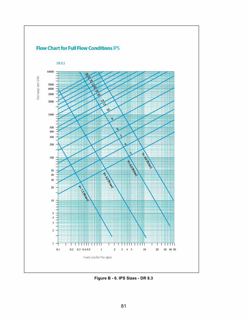
81
Figure B - 6. IPS Sizes - DR 8.3
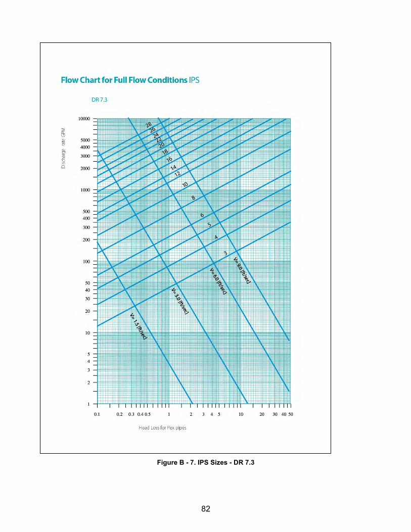
82
Figure B - 7. IPS Sizes - DR 7.3

83
Figure B - 8. Metric Sizes – DR 26

84
Figure B - 9. Metric Sizes - DR 16.2

85
Figure B - 10. Metric Sizes – DR 13.6

86
Figure B - 11. Metric Sizes – DR 11

87
Figure B - 12. Metric Sizes - DR 9
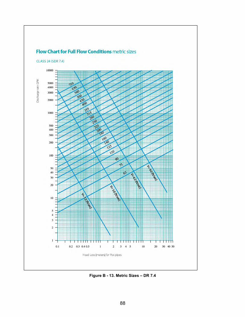
88
Figure B - 13. Metric Sizes – DR 7.4

89
Figure B - 14. Metric Sizes – DR 6