pgw 2200 softswitch rlm timer informationrlm timer information one rlm group is configured on a...
TRANSCRIPT

PGW 2200 Softswitch RLM Timer Information Contents
IntroductionPrerequisitesRequirementsComponents UsedConventionsRLM Timer InformationOverview and VerificationHow RLM WorksChange RLM Timers on the NAS and the Cisco PGW 2200ISDN Q.921 and Q.931+ConfigureNetwork DiagramConfigurationsVerifyTroubleshootTroubleshooting CommandsPGW 2200 and NAS Troubleshooting ScenariosBoth Ethernet and FastEthernet Down on the Cisco NASIP Connectivity Problem on Active Link - ''Link Recovered'' MessageRelated Information
Introduction
This document provides a general overview and sample configurations of the Redundant LinkManager (RLM) used in the Cisco PGW 2200 for signaling mode. Information is also provided ontroubleshooting the RLM signaling and ISDN signaling between the network access server (NAS)gateway and Cisco PGW 2200.
The RLM provides virtual link management over multiple IP networks so that the Cisco Q.931+signaling protocol can be transported on top of multiple redundant links between Cisco PGW 2200and Cisco NAS.
RLM provides:
A client/server relationship—NAS RLM is always the client and switches a link when afailure is detected.
●
Polling mechanism—Periodically sends ''hello'' on all configured links to ensure availability.●
Maintain Link Integrity—Control messages are exchanged out-of-ban on the same IPaddress pair. However, different UDP ports are used.
●
Redundant IP connections.●
Message oriented service.●
Reliability and performance.●

Figure 1: Overview on Extended Q.931 and RLM
Prerequisites
Requirements
Cisco recommends that you have knowledge of these topics:
Redundant Link Manager●
RLM Configuration●
Cisco Media Gateway Controller Software Release 9 Documentation●
Components Used
The information in this document is based on Cisco PGW 2200 Software Release 9.x.
Note: The RLM details are part of Cisco PGW 2200 version 7.4(11) and 7.4(12). However, thisdocument only provides guidelines for Cisco PGW 2200 Release 9.x.
The information in this document was created from the devices in a specific lab environment. All ofthe devices used in this document started with a cleared (default) configuration. If your network islive, make sure that you understand the potential impact of any command.
Conventions
Refer to Cisco Technical Tips Conventions for more information on document conventions.
RLM Timer Information
One RLM group is configured on a gateway and two Cisco PGW 2200s are configured within theRLM group. One has the IP address and UDP port for the active Cisco PGW 2200 and the otherhas the IP address and UDP port of the standby Cisco PGW 2200 (see Figure 2).
Each server in the RLM group is supported by two UDP channels on different UDP ports. OneUDP channel (port 3000) transports the RLM protocol and the other UDP channel (port 3001)transports the Q.921 protocol.
The objective of RLM is to insulate the call signaling layers from the indeterminate nature ofnetwork behavior typically associated with IP-based networks. The RLM maintains variousvirtual links between the Cisco PGW 2200 and the remote NAS and continuously monitors thelink state to determine if the outgoing frames should assume an alternative path.
●
Since each different RLM group requires binding to a Cisco PGW 2200 Channel Controller(IOCC) (a specific UDP port required for each), multiple IOCCs are required to support thisconfiguration. Although the Cisco PGW 2200 can support up to eight Primary Rate InterfaceInternet Protocol (PRIIP) IOCCs, each with the capacity for 32 gateways (RLM) or each CiscoPGW 2200 IOCC (PRIIP) supports 32 gateways (RLM). This means that on the Cisco PGW2200, you have ports 3001, 3003, and 3005 through 3015. Use the UNIX command netstat -a| grep 30 to verify this on the Cisco PGW 2200.
●
Information from the XECfgParm.dat file under directory /opt/CiscoMGC/etc:
*.maxNumLinks = 32●
*.maxNumRLMPorts = 8 # Maximum number of unique RLM ports●
The PGW 2200 supports a maximum of eight PRI channel controller processes. These processesare created when you configure the PGW 2200. For example, you use port 3000 and 3001 in yourCisco IOS® / PGW 2200 configuration, for RLM and ISDN. This creates one IOCC for PRI(NI+).Therefore, every time you use a different port another process is created.
Each process supports up to 32 gateways. If you use one RLM per gateway, then you can have256 gateways. But when you have four RLMs per gateway for traffic routing, then you are left witha capacity of 64 physical gateways.
Note: IUA use is supported from Cisco PGW 2200 release 9.4 or later. The support for IUA withSCTP is limited because RLM has limitations in terms of scaling to support large numbers ofNFAS groups per media gateway. Refer to Support for IUA with SCTP for further information.
Note: Do not change this value. Also, be aware that as you increase the RLM sessions you useper Cisco PGW 2200, the fewer total gateways you can support. For example, one RLM supportsa total of 256 gateways per Cisco PGW 2200, two RLMs support a total of 128 gateways perCisco PGW 2200, and so forth.
The gateways are considered the client side and are responsible for the instigation of a switchoverto a lower weight standby RLM link in the event of a failure.
Overview and Verification
Figure 2: The concept of Active /Standby PGW 2200 / RLMThe default UDP port for the RLM management link is 3000.●
The default UDP port for the RLM data link is one plus the value of the RLM management linkUDP port value (for example, 3001).Figure 3: RLM Configuration Information
●
The IOS commands show rlm group x and show ip sockets display the UDP ports in useon the IOS NAS.
●
The nfas_int in the E1/T1 controller must match the spanID in the Cisco PGW 2200 bearerchannel configuration. This is a key point in the channel mapping. It is transported in theChannelD IE of the Q.931 setup message together with the timeslot.
●
How RLM Works
RLM Packet Format and Protocol Stack
The RLM link management packet consists of six bytes as this diagram shows.
The current supported versions of RLM in the PGW 2200 is version 2.0 only.
The control field provides the command to the peer. These are valid control values:
RLM_START_REQ (0x01)—Used to initiate an RLM link. Only generated by the NAS.●
RLM_START_ACK (0x02)—Generated by the PGW 2200 to acknowledge the start of anRLM link.
●
RLM_STOP_REQ (0x03)—Generated by either the PGW 2200 or the NAS to stop a link.●
RLM_STOP_ACK (0x04)—Acknowledgement to a stop request.●
RLM_ECHO_REQ (0x05)—Used by the NAS only to periodically ping the PGW 2200 in orderto verify link integrity. Used on both an active link and all standby links.
●
RLM_ECHO_ACK (0x06)—Acknowledgement of an echo request.●
RLM_SWITCH_REQ (0x07)—Used to switch from a lower weighted active RLM link to ahigher weighted available link.
●
RLM_SWITCH_ACK (0x08)—Acknowledgement of a switch request.●
The packet length is the length of the RLM management packet (UDP payload). For RLM version1.0, this value is always 6. For RLM version 2, this value is 8.
The sequence number is a unique value used to correlate a specific command request andacknowledgement.
Figure 4: RLM Message Flow for Link RecoveryIn Figure 4, the client RLM on the NAS initiates a request to the Cisco PGW 2200 to start an RLMsession. Assume the NAS is configured to give the first link a higher priority. After the Cisco PGW2200 acknowledges the start request, the link is considered available and data packets can besent on the data UDP port. The second link is placed in a standby mode. The RLM periodicallysends the echo requests to all configured RLM links in a given RLM group. The default interval is 1second.
In regards to the TIMEOUT issues in Figure 4, if the active link does not receive a response to oneof the RLM echo requests, it attempts to retry the request (default value is three attempts). Uponfailure to receive an acknowledgement, the client RLM initiates a link recovery by sending a startrequest to the next highest weighted standby link available. The client RLM continues to poll thepreviously active link. If a response is eventually received, it performs a link switchover back to thehigher weighted link. If the link weights are identical, the RLM client selects the link where the startacknowledge is first received. For the standby Cisco PGW 2200, the RLM server does notacknowledge the echo requests from the NAS while in the standby state. Once the standbybecomes the active server and all call states are restored, the RLM starts to acknowledge therequests from the NAS.
The behavior of RLM is such that RLM keepalives are only transmitted when signaling traffic hasnot been transmitted for some time. For instance, the receipt of a signaling message (for example,Q.921) has the effect of resetting the RLM keepalive timer. Note also that RLM keepalives are onlytransmitted by the NAS. The Cisco PGW 2200 only responds to RLM keepalive requests.However, if the RLM keepalive timer expires on the Cisco PGW 2200, it brings down the link.Increasing the RLM keepalive timer values on both sides (PGW 2200 and NAS) ensures that theRLM link is not reset during transient conditions in the IP network during which the default RLMkeepalive timer value may be too stringent. For a single Cisco PGW 2200, there is no penalty fordoing this. With two Cisco PGW 2200s in a failover configuration, there is a trade-off betweenavoiding flaps in the RLM link and quickly detecting a link failure. With RLM, keepalive timers andQ.921/Q.931 timers increased.
When you look at the control RLM information messages (see Figure 5), the control field providesthe command to the peer. The values in Figure 5 are valid control values:
Figure 5: RLM Message Information
Change RLM Timers on the NAS and the Cisco PGW 2200
This section is designed to preserve stable calls during Cisco PGW 2200 failover or underconditions of transient IP network instability. These changes ensure that calls are retained unless
there is prolonged loss of RLM connectivity. Loss of RLM connectivity means there are noavailable links to carry signaling traffic between the NAS and the active Cisco PGW 2200. Loss ofa single link is handled by the RLM layer transparently to the ISDN stack.
With the show rlm group <x> command on the IOS NAS, you can check the timers of the RLM.
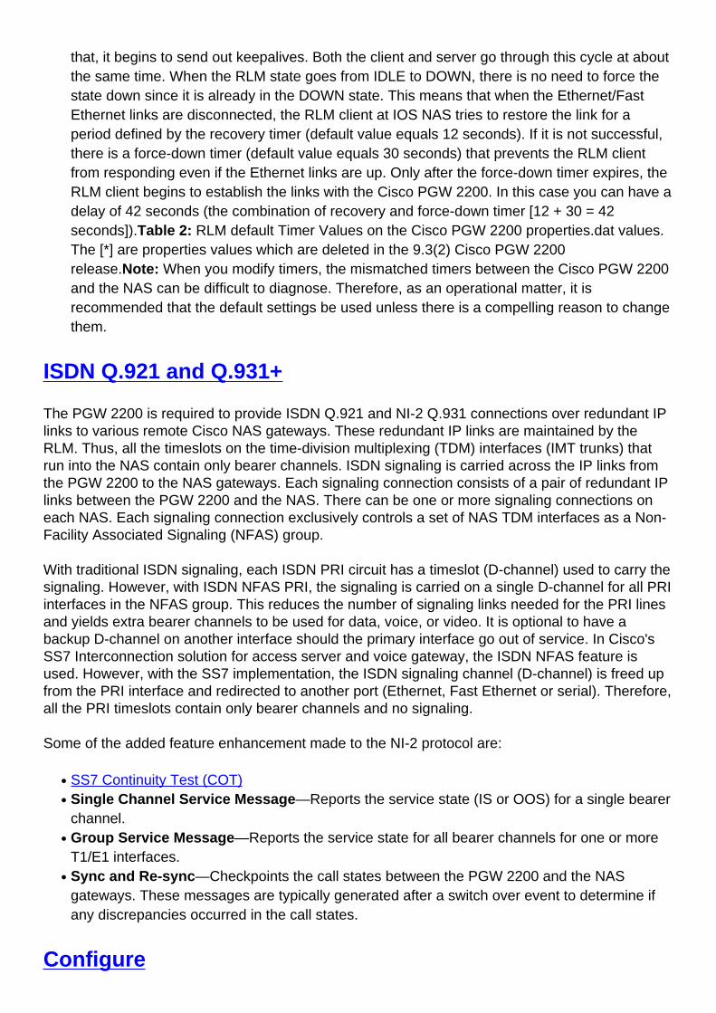
Table 1: RLM Default Timer Values on the Cisco IOS NAS
Timer DurationOpen Wait 3 seconds
Recovery 12 seconds
Minimum-up 60 seconds
Keepalive 1 second
Force-down 30 seconds
Switch-link 5 seconds
Retransmit 1 second
The force-down time needs to be longer than the total keepalive time (keepalive period *retries) plus the recovery time. For example, see this formula:force-down > (Keepalive *Retries) + recovery By default the retries = 3 timesFor this example, 30 > (1 * 3) + 12If theforce-down and keepalive timer has the same value, then the IOS NAS cannot recognize thatthe link is reset because the keepalive is greater than or equal to the force down time.
●
Keepalive Timer—The IOS NAS sends ECHO_REQ every 1 second. After three lostECHO_REQ, NAS thinks the link might be down and it starts a recovery timer (12 seconds).However, it continues to send ECHO_REQ expecting that the link might come back up. Payattention to this in older Cisco IOS versions, the recovery timers at the default values are toolong. There were instances where the RLM link could be taken down. The best item is tocheck these timers on both systems. During the startup/shutdown of the standby Cisco PGW2200, the active Cisco PGW 2200 is delayed in its response to the ECHO_REQ from the IOSNAS. After three tries from the IOS NAS, each with a default of one second timeout, the IOSNAS brings down the RLM link. By increasing the keepalive timer from 1 second to 10seconds, it is possible to keep the active RLM up. This way, the IOS NAS waits longer aftereach ECHO_REQ before timing out and trying again. With a 10 second keepalive, the IOSNAS can wait 30 seconds before timing out and bringing down the RLM link. However, in thisinstance, if you change the keepalive timers, you need to take attention on the force-downtimer as well.
●
Recovery Timer—If you want to reduce the recovery timer, bring down the active RLM linkquickly before the Cisco PGW 2200 restarts. This is done by configuring both the keepalivetimer and force-down timer in the same value. Therefore, when IOS NAS is reloaded andcomes back, the remote IOS NAS cannot recognize that the link is reset because thekeepalive is greater than or equal to the force-down time. The force-down time needs to begreater than the total keepalive time (keepalive period * retries) plus the recovery time. Thecorrection is that the force-down timer must be greater then three times the keepalive plus therecovery timer.
●
Force-down Timer—According to the specification, RLM remains in the Recovery state forabout 15 seconds (number of ECHO_REQ every 1 second plus Recovery every 12 seconds).If the link does not come back within that time frame, the RLM state goes to the DOWN stateand is forced to stay down for 30 seconds as a default to avoid the ping-pong effect. After
●
that, it begins to send out keepalives. Both the client and server go through this cycle at aboutthe same time. When the RLM state goes from IDLE to DOWN, there is no need to force thestate down since it is already in the DOWN state. This means that when the Ethernet/FastEthernet links are disconnected, the RLM client at IOS NAS tries to restore the link for aperiod defined by the recovery timer (default value equals 12 seconds). If it is not successful,there is a force-down timer (default value equals 30 seconds) that prevents the RLM clientfrom responding even if the Ethernet links are up. Only after the force-down timer expires, theRLM client begins to establish the links with the Cisco PGW 2200. In this case you can have adelay of 42 seconds (the combination of recovery and force-down timer [12 + 30 = 42seconds]).Table 2: RLM default Timer Values on the Cisco PGW 2200 properties.dat values.The [*] are properties values which are deleted in the 9.3(2) Cisco PGW 2200release.Note: When you modify timers, the mismatched timers between the Cisco PGW 2200and the NAS can be difficult to diagnose. Therefore, as an operational matter, it isrecommended that the default settings be used unless there is a compelling reason to changethem.
ISDN Q.921 and Q.931+
The PGW 2200 is required to provide ISDN Q.921 and NI-2 Q.931 connections over redundant IPlinks to various remote Cisco NAS gateways. These redundant IP links are maintained by theRLM. Thus, all the timeslots on the time-division multiplexing (TDM) interfaces (IMT trunks) thatrun into the NAS contain only bearer channels. ISDN signaling is carried across the IP links fromthe PGW 2200 to the NAS gateways. Each signaling connection consists of a pair of redundant IPlinks between the PGW 2200 and the NAS. There can be one or more signaling connections oneach NAS. Each signaling connection exclusively controls a set of NAS TDM interfaces as a Non-Facility Associated Signaling (NFAS) group.
With traditional ISDN signaling, each ISDN PRI circuit has a timeslot (D-channel) used to carry thesignaling. However, with ISDN NFAS PRI, the signaling is carried on a single D-channel for all PRIinterfaces in the NFAS group. This reduces the number of signaling links needed for the PRI linesand yields extra bearer channels to be used for data, voice, or video. It is optional to have abackup D-channel on another interface should the primary interface go out of service. In Cisco'sSS7 Interconnection solution for access server and voice gateway, the ISDN NFAS feature isused. However, with the SS7 implementation, the ISDN signaling channel (D-channel) is freed upfrom the PRI interface and redirected to another port (Ethernet, Fast Ethernet or serial). Therefore,all the PRI timeslots contain only bearer channels and no signaling.
Some of the added feature enhancement made to the NI-2 protocol are:
SS7 Continuity Test (COT)●
Single Channel Service Message—Reports the service state (IS or OOS) for a single bearerchannel.
●
Group Service Message—Reports the service state for all bearer channels for one or moreT1/E1 interfaces.
●
Sync and Re-sync—Checkpoints the call states between the PGW 2200 and the NASgateways. These messages are typically generated after a switch over event to determine ifany discrepancies occurred in the call states.
●
Configure

This section presents you with the information to configure the features this document describes.
Note: Use the Command Lookup Tool (registered customers only) to find additional information onthe commands this document uses.
Configuration on the NAS gateway is simple. Every NAS gateway has one or more RLM groupsdefined. Within the RLM group, and if the PGW 2200 is in redundant mode, there are two serverlink groups (one for the Active PGW 2200 and another one for the Standby PGW 2200). Eachserver link group can have one or two links that connect to the each of the PGW 2200 Ethernet(E0 and/or E1) interfaces. The NAS gateway can use either of its interfaces (loopback, Ethernet,or Fast Ethernet) as the source address to create the links to the PGW 2200. For full redundancy,the NAS gateway connects two Ethernet interfaces to both PGW 2200s. One Ethernet connects toboth PGW 2200 hme0 interfaces in one VLAN. The other Ethernet interface connects to bothPGW 2200 hme1 interfaces in another VLAN. See this diagram for a full redundancy setup.
Network Diagram
This document uses this network setup:
Configurations
For step-by-step instructions on how to set up the RLM group to talk to with the PGW 2200, referto Configuring Media Gateways for the SS7 Interconnect for Voice Gateways Solution andRedundant Link Manager (RLM).
This document does not cover the step-by-step instructions on how to provision the PGW 2200 forSS7 Interconnection. Refer to these documentation for more detailed information:
Cisco Media Gateway Controller Release 7 Documentation●
Cisco SS7 Interconnect for Voice Gateways Solution, Release 1.1●
Cisco MGC Software Release 7 Installation & Configuration Guide●
Cisco MGC Release 7 Provisioning Guide●
Instead, this document concentrates on the area related to the NAS setup and verification andtroubleshooting from the PGW 2200 perspective.
This is a sample configuration setup for the NAS gateway. Note that our lab setup is not fullyredundant. The NAS gateway only has one signaling link defined to each of the PGW 2200s.
PGW2200 on the NAS
isdn switch-type primary-ni
!--- Define the switch-type to use. !--- For SS7, this
must be primary-ni.
!
controller T1 0
framing esf
clock source line primary
linecode b8zs
pri-group timeslots 1-24 nfas_d primary nfas_int 0
nfas_group 0
!--- Configure the NFAS group 0. ! interface Serial0:23

no ip address encapsulation ppp isdn switch-type
primary-ni
!--- Define the switch-type to use. !--- For SS7, this
must be primary-ni.
isdn incoming-voice modem
isdn rlm-group 0
!--- Bind the RLM group 0 to the D-channel. !--- This
causes the ISDN signaling to go over IP instead of the
TDM D-channel. no isdn send-status-enquiry !---
Timeslot24. isdn negotiate-bchan resend-setup isdn
bchan-number-order ascending ! interface FastEthernet0
ip address 172.16.13.141 255.255.255.224 duplex auto
speed auto ! rlm group 0
!--- Define the RLM group parameters to talk with the
PGW 2200. server sc1
!--- Specify the first PGW 2200 and IP addresses used to
setup the link. link address 172.16.13.132 source
FastEthernet0 weight 2
server sc3
!--- Specify the first PGW 2200 and IP addresses used to
setup the link. LINK ADDRESS 172.16.13.134 SOURCE
FASTETHERNET0 WEIGHT 1 !
Verify
This section provides information you can use to confirm your configuration works properly.
Certain show commands are supported by the Output Interpreter Tool (registered customers only), which allows you to view an analysis of show command output.
show rlm group—Verifies that the RLM group is up and running on the NAS gateway.●
show isdn status—Verifies that the ISDN signaling works properly on the NAS gateway.●
show controller t1—Verifies that all the controller T1/E1s are up and running clean on theNAS gateway.
●
show isdn service—Verifies that all the bearer channels are in service on the NAS gateway.●
rtrv-ne—Verifies that the PGW 2200 is up and active.●
rtrv-softw:all—Verifies that all software processes run on the PGW 2200.●
rtrv-sc:all—Verifies that all the signaling links are in service on the PGW 2200.●
rtrv-dest:all—Verifies that all the destination links are in service on the PGW 2200.●
rtrv-tc:all—Verifies that all the CICs are up and idle from both the SS7 and NAS gatewayperspectives.
●
Check for these items on the NAS gateway:
Make sure that the RLM group is up and runs using the show rlm group command.●
Make sure the ISDN signaling works properly using the show isdn status command.●
Make sure all the controller T1/E1s are up and running clean using the show controller t1command.
●
Make sure all the bearer channels are in service using the show isdn service command.●
Check for these items on the PGW 2200:
Make sure the system is up and active using the rtrv-ne MML command.●
Make sure all the software processes are running using the rtrv-softw:all MML command.●
Make sure all the signaling links are in service using the rtrv-sc:all MML command.●
Make sure all the destination links are in service using the rtrv-dest:all MML command.●
Make sure all the CICs are up and IDLE from both the SS7 and NAS gateway perspectiveusing the rtrv-tc:all MML command.
●
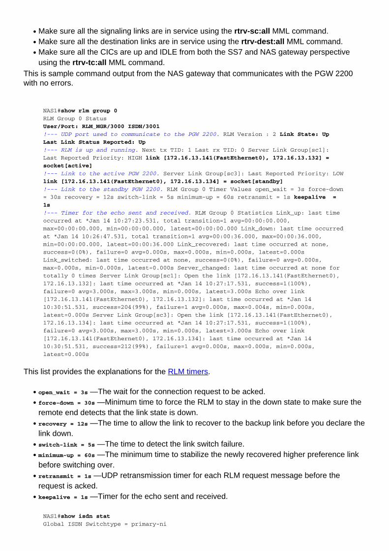
This is sample command output from the NAS gateway that communicates with the PGW 2200with no errors.
NAS1#show rlm group 0
RLM Group 0 Status
User/Port: RLM_MGR/3000 ISDN/3001
!--- UDP port used to communicate to the PGW 2200. RLM Version : 2 Link State: Up
Last Link Status Reported: Up
!--- RLM is up and running. Next tx TID: 1 Last rx TID: 0 Server Link Group[sc1]:
Last Reported Priority: HIGH link [172.16.13.141(FastEthernet0), 172.16.13.132] =
socket[active]
!--- Link to the active PGW 2200. Server Link Group[sc3]: Last Reported Priority: LOW
link [172.16.13.141(FastEthernet0), 172.16.13.134] = socket[standby]
!--- Link to the standby PGW 2200. RLM Group 0 Timer Values open_wait = 3s force-down
= 30s recovery = 12s switch-link = 5s minimum-up = 60s retransmit = 1s keepalive =
1s
!--- Timer for the echo sent and received. RLM Group 0 Statistics Link_up: last time
occurred at *Jan 14 10:27:23.531, total transition=1 avg=00:00:00.000,
max=00:00:00.000, min=00:00:00.000, latest=00:00:00.000 Link_down: last time occurred
at *Jan 14 10:26:47.531, total transition=1 avg=00:00:36.000, max=00:00:36.000,
min=00:00:00.000, latest=00:00:36.000 Link_recovered: last time occurred at none,
success=0(0%), failure=0 avg=0.000s, max=0.000s, min=0.000s, latest=0.000s
Link_switched: last time occurred at none, success=0(0%), failure=0 avg=0.000s,
max=0.000s, min=0.000s, latest=0.000s Server_changed: last time occurred at none for
totally 0 times Server Link Group[sc1]: Open the link [172.16.13.141(FastEthernet0),
172.16.13.132]: last time occurred at *Jan 14 10:27:17.531, success=1(100%),
failure=0 avg=3.000s, max=3.000s, min=0.000s, latest=3.000s Echo over link
[172.16.13.141(FastEthernet0), 172.16.13.132]: last time occurred at *Jan 14
10:30:51.531, success=204(99%), failure=1 avg=0.000s, max=0.004s, min=0.000s,
latest=0.000s Server Link Group[sc3]: Open the link [172.16.13.141(FastEthernet0),
172.16.13.134]: last time occurred at *Jan 14 10:27:17.531, success=1(100%),
failure=0 avg=3.000s, max=3.000s, min=0.000s, latest=3.000s Echo over link
[172.16.13.141(FastEthernet0), 172.16.13.134]: last time occurred at *Jan 14
10:30:51.531, success=212(99%), failure=1 avg=0.000s, max=0.000s, min=0.000s,
latest=0.000s
This list provides the explanations for the RLM timers.
open_wait = 3s —The wait for the connection request to be acked.●
force-down = 30s —Minimum time to force the RLM to stay in the down state to make sure theremote end detects that the link state is down.
●
recovery = 12s —The time to allow the link to recover to the backup link before you declare thelink down.
●
switch-link = 5s —The time to detect the link switch failure.●
minimum-up = 60s —The minimum time to stabilize the newly recovered higher preference linkbefore switching over.
●
retransmit = 1s —UDP retransmission timer for each RLM request message before therequest is acked.
●
keepalive = 1s —Timer for the echo sent and received.●
NAS1#show isdn stat
Global ISDN Switchtype = primary-ni

ISDN Serial0:23 interface rlm-group = 0
!--- D-channel bind to rlm-group 0. dsl 0, interface ISDN Switchtype = primary-ni :
Primary D-channel of nfas group 0 Layer 1 Status: ACTIVE Layer 2 Status: TEI = 0, Ces
= 1, SAPI = 0, State = MULTIPLE_FRAME_ESTABLISHED
!--- Good. Layer 3 Status: 0 Active Layer 3 Call(s) Active dsl 0 CCBs = 0 The Free
Channel Mask: 0x80FFFFFF Total Allocated ISDN CCBs = 0 NAS1#show isdn service
PRI Channel Statistics:
ISDN Se0:23 SC, Channel [1-24]
!--- Note the keyword PGW 2200. In normal ISDN, it is not there. Configured Isdn
Interface (dsl) 0 Channel State (0=Idle 1=Proposed 2=Busy 3=Reserved 4=Restart
5=Maint_Pend) Channel : 1 2 3 4 5 6 7 8 9 0 1 2 3 4 5 6 7 8 9 0 1 2 3 4 State : 0 0 0
0 0 0 0 0 0 0 0 0 0 0 0 0 0 0 0 0 0 0 0 0
!--- All timeslots are good and idle including timeslot 24. Service State
(0=Inservice 1=Maint 2=Outofservice) Channel : 1 2 3 4 5 6 7 8 9 0 1 2 3 4 5 6 7 8 9
0 1 2 3 4 State : 0 0 0 0 0 0 0 0 0 0 0 0 0 0 0 0 0 0 0 0 0 0 0 0
NAS1#
NAS1#show controller t1
T1 0 is up.
!--- T1 is up and running clean with no errors. Applique type is Channelized T1
Cablelength is short 133 No alarms detected. alarm-trigger is not set Version info of
slot 0: HW: 4, PLD Rev: 0 Manufacture Cookie Info: EEPROM Type 0x0001, EEPROM Version
0x01, Board ID 0x42, Board Hardware Version 1.32, Item Number 73-2217-05, Board
Revision B16, Serial Number 10077744, PLD/ISP Version 0.0, Manufacture Date 25-Sep-
1998. Framing is ESF, Line Code is B8ZS, Clock Source is Line Primary.
!--- T1 physical layer configuration. Data in current interval (429 seconds elapsed):
0 Line Code Violations, 0 Path Code Violations 0 Slip Secs, 0 Fr Loss Secs, 0 Line
Err Secs, 0 Degraded Mins 0 Errored Secs, 0 Bursty Err Secs, 0 Severely Err Secs, 0
Unavail Secs Total Data (last 3 15 minute intervals): 0 Line Code Violations, 0 Path
Code Violations, 0 Slip Secs, 0 Fr Loss Secs, 0 Line Err Secs, 0 Degraded Mins, 0
Errored Secs, 0 Bursty Err Secs, 0 Severely Err Secs, 0 Unavail Secs
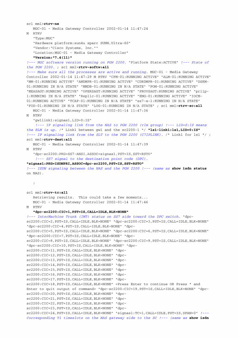
This is example command output from the PGW 2200. It details items to check for duringverification.
sc1 mml>rtrv-ne
MGC-01 - Media Gateway Controller 2002-01-14 11:47:24
M RTRV
"Type:MGC"
"Hardware platform:sun4u sparc SUNW,Ultra-60"
"Vendor:"Cisco Systems, Inc.""
"Location:MGC-01 - Media Gateway Controller"
"Version:"7.4(11)"
!--- MGC software version running on PGW 2200. "Platform State:ACTIVE" !--- State of
the PGW 2200. ; sc1 mml>rtrv-softw:all
!--- Make sure all the processes are active and running. MGC-01 - Media Gateway
Controller 2002-01-14 11:47:29 M RTRV "CFM-01:RUNNING ACTIVE" "ALM-01:RUNNING ACTIVE"
"MM-01:RUNNING ACTIVE" "AMDMPR-01:RUNNING ACTIVE" "CDRDMPR-01:RUNNING ACTIVE" "DSKM-
01:RUNNING IN N/A STATE" "MMDB-01:RUNNING IN N/A STATE" "POM-01:RUNNING ACTIVE"
"MEASAGT:RUNNING ACTIVE" "OPERSAGT:RUNNING ACTIVE" "PROVSAGT:RUNNING ACTIVE" "priip-
1:RUNNING IN N/A STATE" "Replic-01:RUNNING ACTIVE" "ENG-01:RUNNING ACTIVE" "IOCM-
01:RUNNING ACTIVE" "TCAP-01:RUNNING IN N/A STATE" "ss7-a-1:RUNNING IN N/A STATE"
"FOD-01:RUNNING IN N/A STATE" "LOG-01:RUNNING IN N/A STATE" ; sc1 mml>rtrv-sc:all
MGC-01 - Media Gateway Controller 2002-01-14 11:47:36
M RTRV
"gw1link1:signas1,LID=0:IS"
!--- IP signaling link from the NAS to PGW 2200 (rlm group) !--- LID=0:IS means
the RLM is up. /* Link1 between gw1 and the sc2200-1 */ "ls1-link1:ls1,LID=0:IS"
!--- IP signaling link from the SLT to the PGW 2200 (C7IPLINK). /* Link1 for ls1 */ ;
sc1 mml>rtrv-dest:all
MGC-01 - Media Gateway Controller 2002-01-14 11:47:39
M RTRV
"dpc-sc2200:PKG=SS7-ANSI,ASSOC=signas1,PST=IS,SST=RSTO"
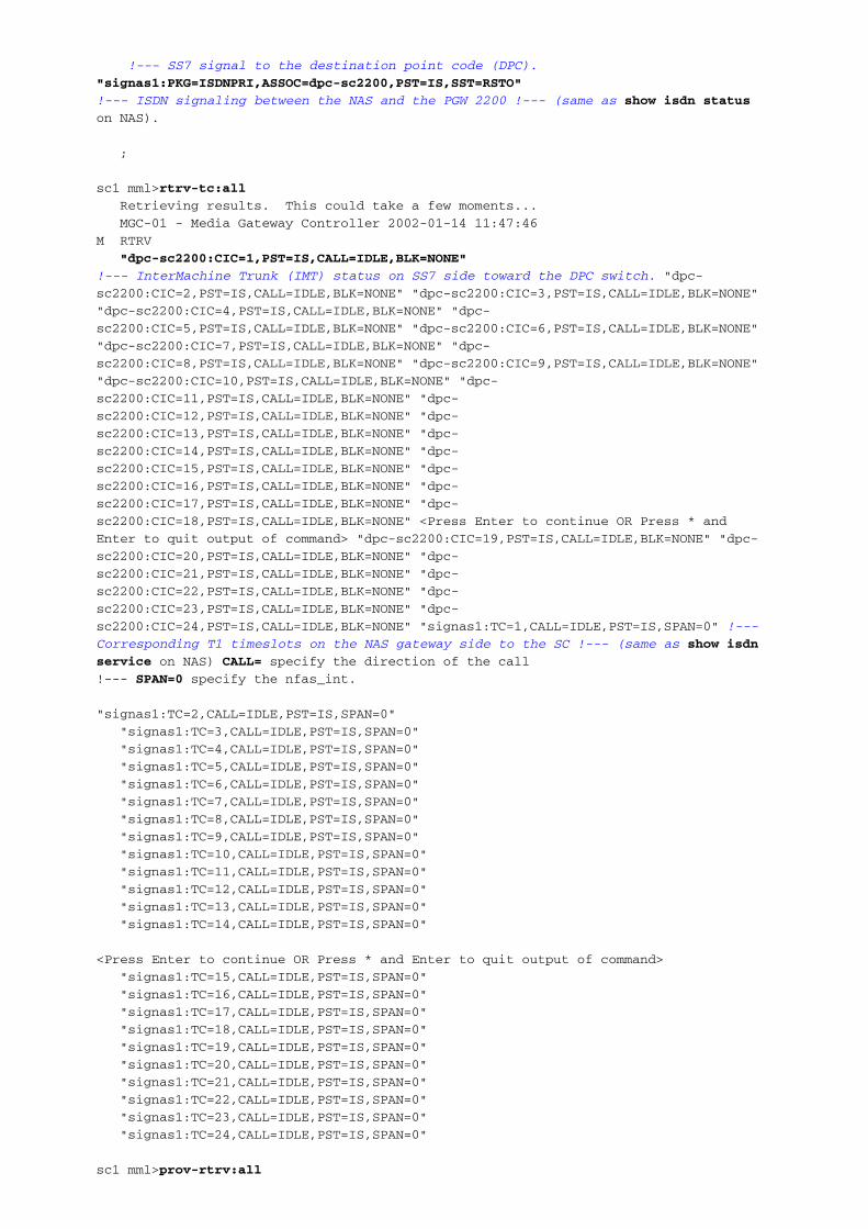
!--- SS7 signal to the destination point code (DPC).
"signas1:PKG=ISDNPRI,ASSOC=dpc-sc2200,PST=IS,SST=RSTO"
!--- ISDN signaling between the NAS and the PGW 2200 !--- (same as show isdn status
on NAS).
;
sc1 mml>rtrv-tc:all
Retrieving results. This could take a few moments...
MGC-01 - Media Gateway Controller 2002-01-14 11:47:46
M RTRV
"dpc-sc2200:CIC=1,PST=IS,CALL=IDLE,BLK=NONE"
!--- InterMachine Trunk (IMT) status on SS7 side toward the DPC switch. "dpc-
sc2200:CIC=2,PST=IS,CALL=IDLE,BLK=NONE" "dpc-sc2200:CIC=3,PST=IS,CALL=IDLE,BLK=NONE"
"dpc-sc2200:CIC=4,PST=IS,CALL=IDLE,BLK=NONE" "dpc-
sc2200:CIC=5,PST=IS,CALL=IDLE,BLK=NONE" "dpc-sc2200:CIC=6,PST=IS,CALL=IDLE,BLK=NONE"
"dpc-sc2200:CIC=7,PST=IS,CALL=IDLE,BLK=NONE" "dpc-
sc2200:CIC=8,PST=IS,CALL=IDLE,BLK=NONE" "dpc-sc2200:CIC=9,PST=IS,CALL=IDLE,BLK=NONE"
"dpc-sc2200:CIC=10,PST=IS,CALL=IDLE,BLK=NONE" "dpc-
sc2200:CIC=11,PST=IS,CALL=IDLE,BLK=NONE" "dpc-
sc2200:CIC=12,PST=IS,CALL=IDLE,BLK=NONE" "dpc-
sc2200:CIC=13,PST=IS,CALL=IDLE,BLK=NONE" "dpc-
sc2200:CIC=14,PST=IS,CALL=IDLE,BLK=NONE" "dpc-
sc2200:CIC=15,PST=IS,CALL=IDLE,BLK=NONE" "dpc-
sc2200:CIC=16,PST=IS,CALL=IDLE,BLK=NONE" "dpc-
sc2200:CIC=17,PST=IS,CALL=IDLE,BLK=NONE" "dpc-
sc2200:CIC=18,PST=IS,CALL=IDLE,BLK=NONE" <Press Enter to continue OR Press * and
Enter to quit output of command> "dpc-sc2200:CIC=19,PST=IS,CALL=IDLE,BLK=NONE" "dpc-
sc2200:CIC=20,PST=IS,CALL=IDLE,BLK=NONE" "dpc-
sc2200:CIC=21,PST=IS,CALL=IDLE,BLK=NONE" "dpc-
sc2200:CIC=22,PST=IS,CALL=IDLE,BLK=NONE" "dpc-
sc2200:CIC=23,PST=IS,CALL=IDLE,BLK=NONE" "dpc-
sc2200:CIC=24,PST=IS,CALL=IDLE,BLK=NONE" "signas1:TC=1,CALL=IDLE,PST=IS,SPAN=0" !---
Corresponding T1 timeslots on the NAS gateway side to the SC !--- (same as show isdn
service on NAS) CALL= specify the direction of the call
!--- SPAN=0 specify the nfas_int.
"signas1:TC=2,CALL=IDLE,PST=IS,SPAN=0"
"signas1:TC=3,CALL=IDLE,PST=IS,SPAN=0"
"signas1:TC=4,CALL=IDLE,PST=IS,SPAN=0"
"signas1:TC=5,CALL=IDLE,PST=IS,SPAN=0"
"signas1:TC=6,CALL=IDLE,PST=IS,SPAN=0"
"signas1:TC=7,CALL=IDLE,PST=IS,SPAN=0"
"signas1:TC=8,CALL=IDLE,PST=IS,SPAN=0"
"signas1:TC=9,CALL=IDLE,PST=IS,SPAN=0"
"signas1:TC=10,CALL=IDLE,PST=IS,SPAN=0"
"signas1:TC=11,CALL=IDLE,PST=IS,SPAN=0"
"signas1:TC=12,CALL=IDLE,PST=IS,SPAN=0"
"signas1:TC=13,CALL=IDLE,PST=IS,SPAN=0"
"signas1:TC=14,CALL=IDLE,PST=IS,SPAN=0"
<Press Enter to continue OR Press * and Enter to quit output of command>
"signas1:TC=15,CALL=IDLE,PST=IS,SPAN=0"
"signas1:TC=16,CALL=IDLE,PST=IS,SPAN=0"
"signas1:TC=17,CALL=IDLE,PST=IS,SPAN=0"
"signas1:TC=18,CALL=IDLE,PST=IS,SPAN=0"
"signas1:TC=19,CALL=IDLE,PST=IS,SPAN=0"
"signas1:TC=20,CALL=IDLE,PST=IS,SPAN=0"
"signas1:TC=21,CALL=IDLE,PST=IS,SPAN=0"
"signas1:TC=22,CALL=IDLE,PST=IS,SPAN=0"
"signas1:TC=23,CALL=IDLE,PST=IS,SPAN=0"
"signas1:TC=24,CALL=IDLE,PST=IS,SPAN=0"
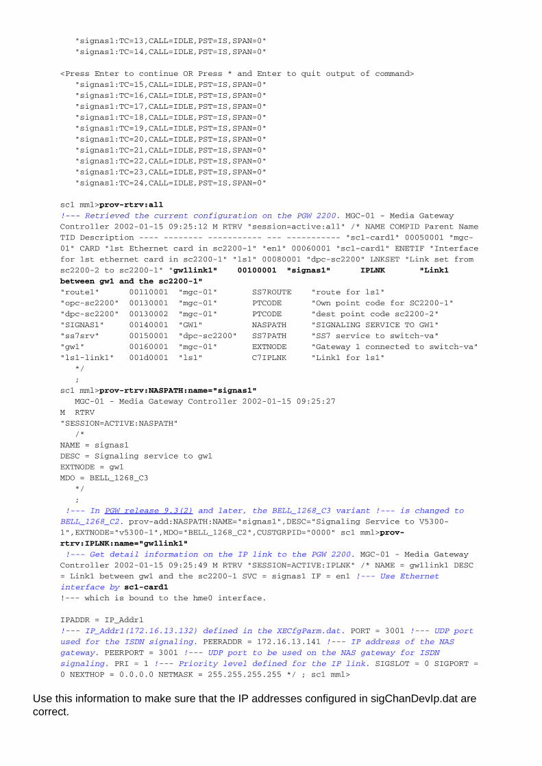
sc1 mml>prov-rtrv:all
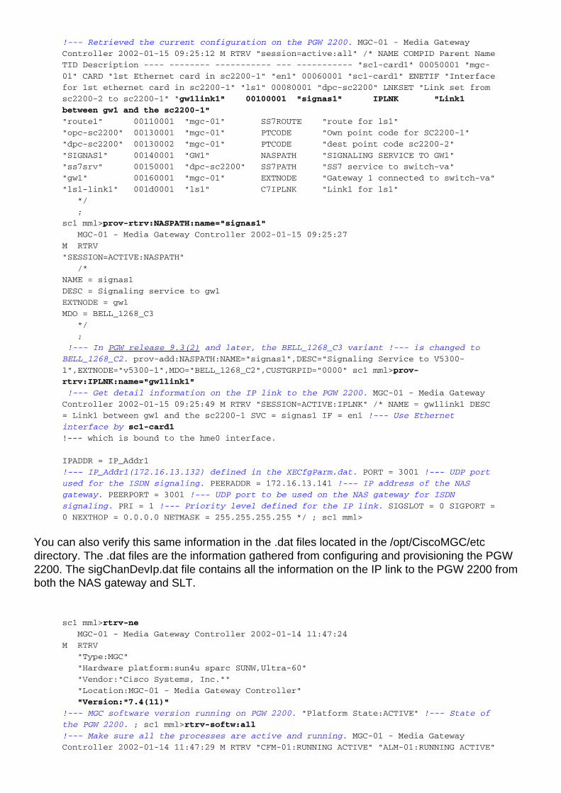
!--- Retrieved the current configuration on the PGW 2200. MGC-01 - Media Gateway
Controller 2002-01-15 09:25:12 M RTRV "session=active:all" /* NAME COMPID Parent Name
TID Description ---- -------- ----------- --- ----------- "sc1-card1" 00050001 "mgc-
01" CARD "1st Ethernet card in sc2200-1" "en1" 00060001 "sc1-card1" ENETIF "Interface
for 1st ethernet card in sc2200-1" "ls1" 00080001 "dpc-sc2200" LNKSET "Link set from
sc2200-2 to sc2200-1" "gw1link1" 00100001 "signas1" IPLNK "Link1
between gw1 and the sc2200-1"
"route1" 00110001 "mgc-01" SS7ROUTE "route for ls1"
"opc-sc2200" 00130001 "mgc-01" PTCODE "Own point code for SC2200-1"
"dpc-sc2200" 00130002 "mgc-01" PTCODE "dest point code sc2200-2"
"SIGNAS1" 00140001 "GW1" NASPATH "SIGNALING SERVICE TO GW1"
"ss7srv" 00150001 "dpc-sc2200" SS7PATH "SS7 service to switch-va"
"gw1" 00160001 "mgc-01" EXTNODE "Gateway 1 connected to switch-va"
"ls1-link1" 001d0001 "ls1" C7IPLNK "Link1 for ls1"
*/
;
sc1 mml>prov-rtrv:NASPATH:name="signas1"
MGC-01 - Media Gateway Controller 2002-01-15 09:25:27
M RTRV
"SESSION=ACTIVE:NASPATH"
/*
NAME = signas1
DESC = Signaling service to gw1
EXTNODE = gw1
MDO = BELL_1268_C3
*/
;
!--- In PGW release 9.3(2) and later, the BELL_1268_C3 variant !--- is changed to
BELL_1268_C2. prov-add:NASPATH:NAME="signas1",DESC="Signaling Service to V5300-
1",EXTNODE="v5300-1",MDO="BELL_1268_C2",CUSTGRPID="0000" sc1 mml>prov-
rtrv:IPLNK:name="gw1link1"
!--- Get detail information on the IP link to the PGW 2200. MGC-01 - Media Gateway
Controller 2002-01-15 09:25:49 M RTRV "SESSION=ACTIVE:IPLNK" /* NAME = gw1link1 DESC
= Link1 between gw1 and the sc2200-1 SVC = signas1 IF = en1 !--- Use Ethernet
interface by sc1-card1
!--- which is bound to the hme0 interface.
IPADDR = IP_Addr1
!--- IP_Addr1(172.16.13.132) defined in the XECfgParm.dat. PORT = 3001 !--- UDP port
used for the ISDN signaling. PEERADDR = 172.16.13.141 !--- IP address of the NAS
gateway. PEERPORT = 3001 !--- UDP port to be used on the NAS gateway for ISDN
signaling. PRI = 1 !--- Priority level defined for the IP link. SIGSLOT = 0 SIGPORT =
0 NEXTHOP = 0.0.0.0 NETMASK = 255.255.255.255 */ ; sc1 mml>
You can also verify this same information in the .dat files located in the /opt/CiscoMGC/etcdirectory. The .dat files are the information gathered from configuring and provisioning the PGW2200. The sigChanDevIp.dat file contains all the information on the IP link to the PGW 2200 fromboth the NAS gateway and SLT.
sc1 mml>rtrv-ne
MGC-01 - Media Gateway Controller 2002-01-14 11:47:24
M RTRV
"Type:MGC"
"Hardware platform:sun4u sparc SUNW,Ultra-60"
"Vendor:"Cisco Systems, Inc.""
"Location:MGC-01 - Media Gateway Controller"
"Version:"7.4(11)"
!--- MGC software version running on PGW 2200. "Platform State:ACTIVE" !--- State of
the PGW 2200. ; sc1 mml>rtrv-softw:all
!--- Make sure all the processes are active and running. MGC-01 - Media Gateway
Controller 2002-01-14 11:47:29 M RTRV "CFM-01:RUNNING ACTIVE" "ALM-01:RUNNING ACTIVE"
"MM-01:RUNNING ACTIVE" "AMDMPR-01:RUNNING ACTIVE" "CDRDMPR-01:RUNNING ACTIVE" "DSKM-
01:RUNNING IN N/A STATE" "MMDB-01:RUNNING IN N/A STATE" "POM-01:RUNNING ACTIVE"
"MEASAGT:RUNNING ACTIVE" "OPERSAGT:RUNNING ACTIVE" "PROVSAGT:RUNNING ACTIVE" "priip-
1:RUNNING IN N/A STATE" "Replic-01:RUNNING ACTIVE" "ENG-01:RUNNING ACTIVE" "IOCM-
01:RUNNING ACTIVE" "TCAP-01:RUNNING IN N/A STATE" "ss7-a-1:RUNNING IN N/A STATE"
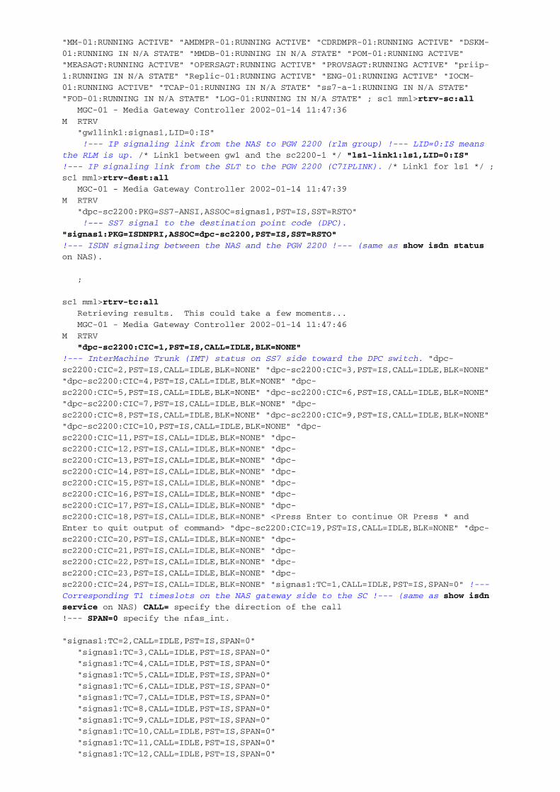
"FOD-01:RUNNING IN N/A STATE" "LOG-01:RUNNING IN N/A STATE" ; sc1 mml>rtrv-sc:all
MGC-01 - Media Gateway Controller 2002-01-14 11:47:36
M RTRV
"gw1link1:signas1,LID=0:IS"
!--- IP signaling link from the NAS to PGW 2200 (rlm group) !--- LID=0:IS means
the RLM is up. /* Link1 between gw1 and the sc2200-1 */ "ls1-link1:ls1,LID=0:IS"
!--- IP signaling link from the SLT to the PGW 2200 (C7IPLINK). /* Link1 for ls1 */ ;
sc1 mml>rtrv-dest:all
MGC-01 - Media Gateway Controller 2002-01-14 11:47:39
M RTRV
"dpc-sc2200:PKG=SS7-ANSI,ASSOC=signas1,PST=IS,SST=RSTO"
!--- SS7 signal to the destination point code (DPC).
"signas1:PKG=ISDNPRI,ASSOC=dpc-sc2200,PST=IS,SST=RSTO"
!--- ISDN signaling between the NAS and the PGW 2200 !--- (same as show isdn status
on NAS).
;
sc1 mml>rtrv-tc:all
Retrieving results. This could take a few moments...
MGC-01 - Media Gateway Controller 2002-01-14 11:47:46
M RTRV
"dpc-sc2200:CIC=1,PST=IS,CALL=IDLE,BLK=NONE"
!--- InterMachine Trunk (IMT) status on SS7 side toward the DPC switch. "dpc-
sc2200:CIC=2,PST=IS,CALL=IDLE,BLK=NONE" "dpc-sc2200:CIC=3,PST=IS,CALL=IDLE,BLK=NONE"
"dpc-sc2200:CIC=4,PST=IS,CALL=IDLE,BLK=NONE" "dpc-
sc2200:CIC=5,PST=IS,CALL=IDLE,BLK=NONE" "dpc-sc2200:CIC=6,PST=IS,CALL=IDLE,BLK=NONE"
"dpc-sc2200:CIC=7,PST=IS,CALL=IDLE,BLK=NONE" "dpc-
sc2200:CIC=8,PST=IS,CALL=IDLE,BLK=NONE" "dpc-sc2200:CIC=9,PST=IS,CALL=IDLE,BLK=NONE"
"dpc-sc2200:CIC=10,PST=IS,CALL=IDLE,BLK=NONE" "dpc-
sc2200:CIC=11,PST=IS,CALL=IDLE,BLK=NONE" "dpc-
sc2200:CIC=12,PST=IS,CALL=IDLE,BLK=NONE" "dpc-
sc2200:CIC=13,PST=IS,CALL=IDLE,BLK=NONE" "dpc-
sc2200:CIC=14,PST=IS,CALL=IDLE,BLK=NONE" "dpc-
sc2200:CIC=15,PST=IS,CALL=IDLE,BLK=NONE" "dpc-
sc2200:CIC=16,PST=IS,CALL=IDLE,BLK=NONE" "dpc-
sc2200:CIC=17,PST=IS,CALL=IDLE,BLK=NONE" "dpc-
sc2200:CIC=18,PST=IS,CALL=IDLE,BLK=NONE" <Press Enter to continue OR Press * and
Enter to quit output of command> "dpc-sc2200:CIC=19,PST=IS,CALL=IDLE,BLK=NONE" "dpc-
sc2200:CIC=20,PST=IS,CALL=IDLE,BLK=NONE" "dpc-
sc2200:CIC=21,PST=IS,CALL=IDLE,BLK=NONE" "dpc-
sc2200:CIC=22,PST=IS,CALL=IDLE,BLK=NONE" "dpc-
sc2200:CIC=23,PST=IS,CALL=IDLE,BLK=NONE" "dpc-
sc2200:CIC=24,PST=IS,CALL=IDLE,BLK=NONE" "signas1:TC=1,CALL=IDLE,PST=IS,SPAN=0" !---
Corresponding T1 timeslots on the NAS gateway side to the SC !--- (same as show isdn
service on NAS) CALL= specify the direction of the call
!--- SPAN=0 specify the nfas_int.
"signas1:TC=2,CALL=IDLE,PST=IS,SPAN=0"
"signas1:TC=3,CALL=IDLE,PST=IS,SPAN=0"
"signas1:TC=4,CALL=IDLE,PST=IS,SPAN=0"
"signas1:TC=5,CALL=IDLE,PST=IS,SPAN=0"
"signas1:TC=6,CALL=IDLE,PST=IS,SPAN=0"
"signas1:TC=7,CALL=IDLE,PST=IS,SPAN=0"
"signas1:TC=8,CALL=IDLE,PST=IS,SPAN=0"
"signas1:TC=9,CALL=IDLE,PST=IS,SPAN=0"
"signas1:TC=10,CALL=IDLE,PST=IS,SPAN=0"
"signas1:TC=11,CALL=IDLE,PST=IS,SPAN=0"
"signas1:TC=12,CALL=IDLE,PST=IS,SPAN=0"
"signas1:TC=13,CALL=IDLE,PST=IS,SPAN=0"
"signas1:TC=14,CALL=IDLE,PST=IS,SPAN=0"
<Press Enter to continue OR Press * and Enter to quit output of command>
"signas1:TC=15,CALL=IDLE,PST=IS,SPAN=0"
"signas1:TC=16,CALL=IDLE,PST=IS,SPAN=0"
"signas1:TC=17,CALL=IDLE,PST=IS,SPAN=0"
"signas1:TC=18,CALL=IDLE,PST=IS,SPAN=0"
"signas1:TC=19,CALL=IDLE,PST=IS,SPAN=0"
"signas1:TC=20,CALL=IDLE,PST=IS,SPAN=0"
"signas1:TC=21,CALL=IDLE,PST=IS,SPAN=0"
"signas1:TC=22,CALL=IDLE,PST=IS,SPAN=0"
"signas1:TC=23,CALL=IDLE,PST=IS,SPAN=0"
"signas1:TC=24,CALL=IDLE,PST=IS,SPAN=0"
sc1 mml>prov-rtrv:all
!--- Retrieved the current configuration on the PGW 2200. MGC-01 - Media Gateway
Controller 2002-01-15 09:25:12 M RTRV "session=active:all" /* NAME COMPID Parent Name
TID Description ---- -------- ----------- --- ----------- "sc1-card1" 00050001 "mgc-
01" CARD "1st Ethernet card in sc2200-1" "en1" 00060001 "sc1-card1" ENETIF "Interface
for 1st ethernet card in sc2200-1" "ls1" 00080001 "dpc-sc2200" LNKSET "Link set from
sc2200-2 to sc2200-1" "gw1link1" 00100001 "signas1" IPLNK "Link1
between gw1 and the sc2200-1"
"route1" 00110001 "mgc-01" SS7ROUTE "route for ls1"
"opc-sc2200" 00130001 "mgc-01" PTCODE "Own point code for SC2200-1"
"dpc-sc2200" 00130002 "mgc-01" PTCODE "dest point code sc2200-2"
"SIGNAS1" 00140001 "GW1" NASPATH "SIGNALING SERVICE TO GW1"
"ss7srv" 00150001 "dpc-sc2200" SS7PATH "SS7 service to switch-va"
"gw1" 00160001 "mgc-01" EXTNODE "Gateway 1 connected to switch-va"
"ls1-link1" 001d0001 "ls1" C7IPLNK "Link1 for ls1"
*/
;
sc1 mml>prov-rtrv:NASPATH:name="signas1"
MGC-01 - Media Gateway Controller 2002-01-15 09:25:27
M RTRV
"SESSION=ACTIVE:NASPATH"
/*
NAME = signas1
DESC = Signaling service to gw1
EXTNODE = gw1
MDO = BELL_1268_C3
*/
;
!--- In PGW release 9.3(2) and later, the BELL_1268_C3 variant !--- is changed to
BELL_1268_C2. prov-add:NASPATH:NAME="signas1",DESC="Signaling Service to V5300-
1",EXTNODE="v5300-1",MDO="BELL_1268_C2",CUSTGRPID="0000" sc1 mml>prov-
rtrv:IPLNK:name="gw1link1"
!--- Get detail information on the IP link to the PGW 2200. MGC-01 - Media Gateway
Controller 2002-01-15 09:25:49 M RTRV "SESSION=ACTIVE:IPLNK" /* NAME = gw1link1 DESC
= Link1 between gw1 and the sc2200-1 SVC = signas1 IF = en1 !--- Use Ethernet
interface by sc1-card1
!--- which is bound to the hme0 interface.
IPADDR = IP_Addr1
!--- IP_Addr1(172.16.13.132) defined in the XECfgParm.dat. PORT = 3001 !--- UDP port
used for the ISDN signaling. PEERADDR = 172.16.13.141 !--- IP address of the NAS
gateway. PEERPORT = 3001 !--- UDP port to be used on the NAS gateway for ISDN
signaling. PRI = 1 !--- Priority level defined for the IP link. SIGSLOT = 0 SIGPORT =
0 NEXTHOP = 0.0.0.0 NETMASK = 255.255.255.255 */ ; sc1 mml>
Use this information to make sure that the IP addresses configured in sigChanDevIp.dat arecorrect.
sc1 mml>rtrv-ne
MGC-01 - Media Gateway Controller 2002-01-14 11:47:24
M RTRV
"Type:MGC"
"Hardware platform:sun4u sparc SUNW,Ultra-60"
"Vendor:"Cisco Systems, Inc.""
"Location:MGC-01 - Media Gateway Controller"
"Version:"7.4(11)"
!--- MGC software version running on PGW 2200. "Platform State:ACTIVE" !--- State of
the PGW 2200. ; sc1 mml>rtrv-softw:all
!--- Make sure all the processes are active and running. MGC-01 - Media Gateway
Controller 2002-01-14 11:47:29 M RTRV "CFM-01:RUNNING ACTIVE" "ALM-01:RUNNING ACTIVE"
"MM-01:RUNNING ACTIVE" "AMDMPR-01:RUNNING ACTIVE" "CDRDMPR-01:RUNNING ACTIVE" "DSKM-
01:RUNNING IN N/A STATE" "MMDB-01:RUNNING IN N/A STATE" "POM-01:RUNNING ACTIVE"
"MEASAGT:RUNNING ACTIVE" "OPERSAGT:RUNNING ACTIVE" "PROVSAGT:RUNNING ACTIVE" "priip-
1:RUNNING IN N/A STATE" "Replic-01:RUNNING ACTIVE" "ENG-01:RUNNING ACTIVE" "IOCM-
01:RUNNING ACTIVE" "TCAP-01:RUNNING IN N/A STATE" "ss7-a-1:RUNNING IN N/A STATE"
"FOD-01:RUNNING IN N/A STATE" "LOG-01:RUNNING IN N/A STATE" ; sc1 mml>rtrv-sc:all
MGC-01 - Media Gateway Controller 2002-01-14 11:47:36
M RTRV
"gw1link1:signas1,LID=0:IS"
!--- IP signaling link from the NAS to PGW 2200 (rlm group) !--- LID=0:IS means
the RLM is up. /* Link1 between gw1 and the sc2200-1 */ "ls1-link1:ls1,LID=0:IS"
!--- IP signaling link from the SLT to the PGW 2200 (C7IPLINK). /* Link1 for ls1 */ ;
sc1 mml>rtrv-dest:all
MGC-01 - Media Gateway Controller 2002-01-14 11:47:39
M RTRV
"dpc-sc2200:PKG=SS7-ANSI,ASSOC=signas1,PST=IS,SST=RSTO"
!--- SS7 signal to the destination point code (DPC).
"signas1:PKG=ISDNPRI,ASSOC=dpc-sc2200,PST=IS,SST=RSTO"
!--- ISDN signaling between the NAS and the PGW 2200 !--- (same as show isdn status
on NAS).
;
sc1 mml>rtrv-tc:all
Retrieving results. This could take a few moments...
MGC-01 - Media Gateway Controller 2002-01-14 11:47:46
M RTRV
"dpc-sc2200:CIC=1,PST=IS,CALL=IDLE,BLK=NONE"
!--- InterMachine Trunk (IMT) status on SS7 side toward the DPC switch. "dpc-
sc2200:CIC=2,PST=IS,CALL=IDLE,BLK=NONE" "dpc-sc2200:CIC=3,PST=IS,CALL=IDLE,BLK=NONE"
"dpc-sc2200:CIC=4,PST=IS,CALL=IDLE,BLK=NONE" "dpc-
sc2200:CIC=5,PST=IS,CALL=IDLE,BLK=NONE" "dpc-sc2200:CIC=6,PST=IS,CALL=IDLE,BLK=NONE"
"dpc-sc2200:CIC=7,PST=IS,CALL=IDLE,BLK=NONE" "dpc-
sc2200:CIC=8,PST=IS,CALL=IDLE,BLK=NONE" "dpc-sc2200:CIC=9,PST=IS,CALL=IDLE,BLK=NONE"
"dpc-sc2200:CIC=10,PST=IS,CALL=IDLE,BLK=NONE" "dpc-
sc2200:CIC=11,PST=IS,CALL=IDLE,BLK=NONE" "dpc-
sc2200:CIC=12,PST=IS,CALL=IDLE,BLK=NONE" "dpc-
sc2200:CIC=13,PST=IS,CALL=IDLE,BLK=NONE" "dpc-
sc2200:CIC=14,PST=IS,CALL=IDLE,BLK=NONE" "dpc-
sc2200:CIC=15,PST=IS,CALL=IDLE,BLK=NONE" "dpc-
sc2200:CIC=16,PST=IS,CALL=IDLE,BLK=NONE" "dpc-
sc2200:CIC=17,PST=IS,CALL=IDLE,BLK=NONE" "dpc-
sc2200:CIC=18,PST=IS,CALL=IDLE,BLK=NONE" <Press Enter to continue OR Press * and
Enter to quit output of command> "dpc-sc2200:CIC=19,PST=IS,CALL=IDLE,BLK=NONE" "dpc-
sc2200:CIC=20,PST=IS,CALL=IDLE,BLK=NONE" "dpc-
sc2200:CIC=21,PST=IS,CALL=IDLE,BLK=NONE" "dpc-
sc2200:CIC=22,PST=IS,CALL=IDLE,BLK=NONE" "dpc-
sc2200:CIC=23,PST=IS,CALL=IDLE,BLK=NONE" "dpc-
sc2200:CIC=24,PST=IS,CALL=IDLE,BLK=NONE" "signas1:TC=1,CALL=IDLE,PST=IS,SPAN=0" !---
Corresponding T1 timeslots on the NAS gateway side to the SC !--- (same as show isdn

service on NAS) CALL= specify the direction of the call
!--- SPAN=0 specify the nfas_int.
"signas1:TC=2,CALL=IDLE,PST=IS,SPAN=0"
"signas1:TC=3,CALL=IDLE,PST=IS,SPAN=0"
"signas1:TC=4,CALL=IDLE,PST=IS,SPAN=0"
"signas1:TC=5,CALL=IDLE,PST=IS,SPAN=0"
"signas1:TC=6,CALL=IDLE,PST=IS,SPAN=0"
"signas1:TC=7,CALL=IDLE,PST=IS,SPAN=0"
"signas1:TC=8,CALL=IDLE,PST=IS,SPAN=0"
"signas1:TC=9,CALL=IDLE,PST=IS,SPAN=0"
"signas1:TC=10,CALL=IDLE,PST=IS,SPAN=0"
"signas1:TC=11,CALL=IDLE,PST=IS,SPAN=0"
"signas1:TC=12,CALL=IDLE,PST=IS,SPAN=0"
"signas1:TC=13,CALL=IDLE,PST=IS,SPAN=0"
"signas1:TC=14,CALL=IDLE,PST=IS,SPAN=0"
<Press Enter to continue OR Press * and Enter to quit output of command>
"signas1:TC=15,CALL=IDLE,PST=IS,SPAN=0"
"signas1:TC=16,CALL=IDLE,PST=IS,SPAN=0"
"signas1:TC=17,CALL=IDLE,PST=IS,SPAN=0"
"signas1:TC=18,CALL=IDLE,PST=IS,SPAN=0"
"signas1:TC=19,CALL=IDLE,PST=IS,SPAN=0"
"signas1:TC=20,CALL=IDLE,PST=IS,SPAN=0"
"signas1:TC=21,CALL=IDLE,PST=IS,SPAN=0"
"signas1:TC=22,CALL=IDLE,PST=IS,SPAN=0"
"signas1:TC=23,CALL=IDLE,PST=IS,SPAN=0"
"signas1:TC=24,CALL=IDLE,PST=IS,SPAN=0"
sc1 mml>prov-rtrv:all
!--- Retrieved the current configuration on the PGW 2200. MGC-01 - Media Gateway
Controller 2002-01-15 09:25:12 M RTRV "session=active:all" /* NAME COMPID Parent Name
TID Description ---- -------- ----------- --- ----------- "sc1-card1" 00050001 "mgc-
01" CARD "1st Ethernet card in sc2200-1" "en1" 00060001 "sc1-card1" ENETIF "Interface
for 1st ethernet card in sc2200-1" "ls1" 00080001 "dpc-sc2200" LNKSET "Link set from
sc2200-2 to sc2200-1" "gw1link1" 00100001 "signas1" IPLNK "Link1
between gw1 and the sc2200-1"
"route1" 00110001 "mgc-01" SS7ROUTE "route for ls1"
"opc-sc2200" 00130001 "mgc-01" PTCODE "Own point code for SC2200-1"
"dpc-sc2200" 00130002 "mgc-01" PTCODE "dest point code sc2200-2"
"SIGNAS1" 00140001 "GW1" NASPATH "SIGNALING SERVICE TO GW1"
"ss7srv" 00150001 "dpc-sc2200" SS7PATH "SS7 service to switch-va"
"gw1" 00160001 "mgc-01" EXTNODE "Gateway 1 connected to switch-va"
"ls1-link1" 001d0001 "ls1" C7IPLNK "Link1 for ls1"
*/
;
sc1 mml>prov-rtrv:NASPATH:name="signas1"
MGC-01 - Media Gateway Controller 2002-01-15 09:25:27
M RTRV
"SESSION=ACTIVE:NASPATH"
/*
NAME = signas1
DESC = Signaling service to gw1
EXTNODE = gw1
MDO = BELL_1268_C3
*/
;
!--- In PGW release 9.3(2) and later, the BELL_1268_C3 variant !--- is changed to
BELL_1268_C2. prov-add:NASPATH:NAME="signas1",DESC="Signaling Service to V5300-
1",EXTNODE="v5300-1",MDO="BELL_1268_C2",CUSTGRPID="0000" sc1 mml>prov-
rtrv:IPLNK:name="gw1link1"
!--- Get detail information on the IP link to the PGW 2200. MGC-01 - Media Gateway
Controller 2002-01-15 09:25:49 M RTRV "SESSION=ACTIVE:IPLNK" /* NAME = gw1link1 DESC
= Link1 between gw1 and the sc2200-1 SVC = signas1 IF = en1 !--- Use Ethernet
interface by sc1-card1
!--- which is bound to the hme0 interface.
IPADDR = IP_Addr1
!--- IP_Addr1(172.16.13.132) defined in the XECfgParm.dat. PORT = 3001 !--- UDP port
used for the ISDN signaling. PEERADDR = 172.16.13.141 !--- IP address of the NAS
gateway. PEERPORT = 3001 !--- UDP port to be used on the NAS gateway for ISDN
signaling. PRI = 1 !--- Priority level defined for the IP link. SIGSLOT = 0 SIGPORT =
0 NEXTHOP = 0.0.0.0 NETMASK = 255.255.255.255 */ ; sc1 mml>
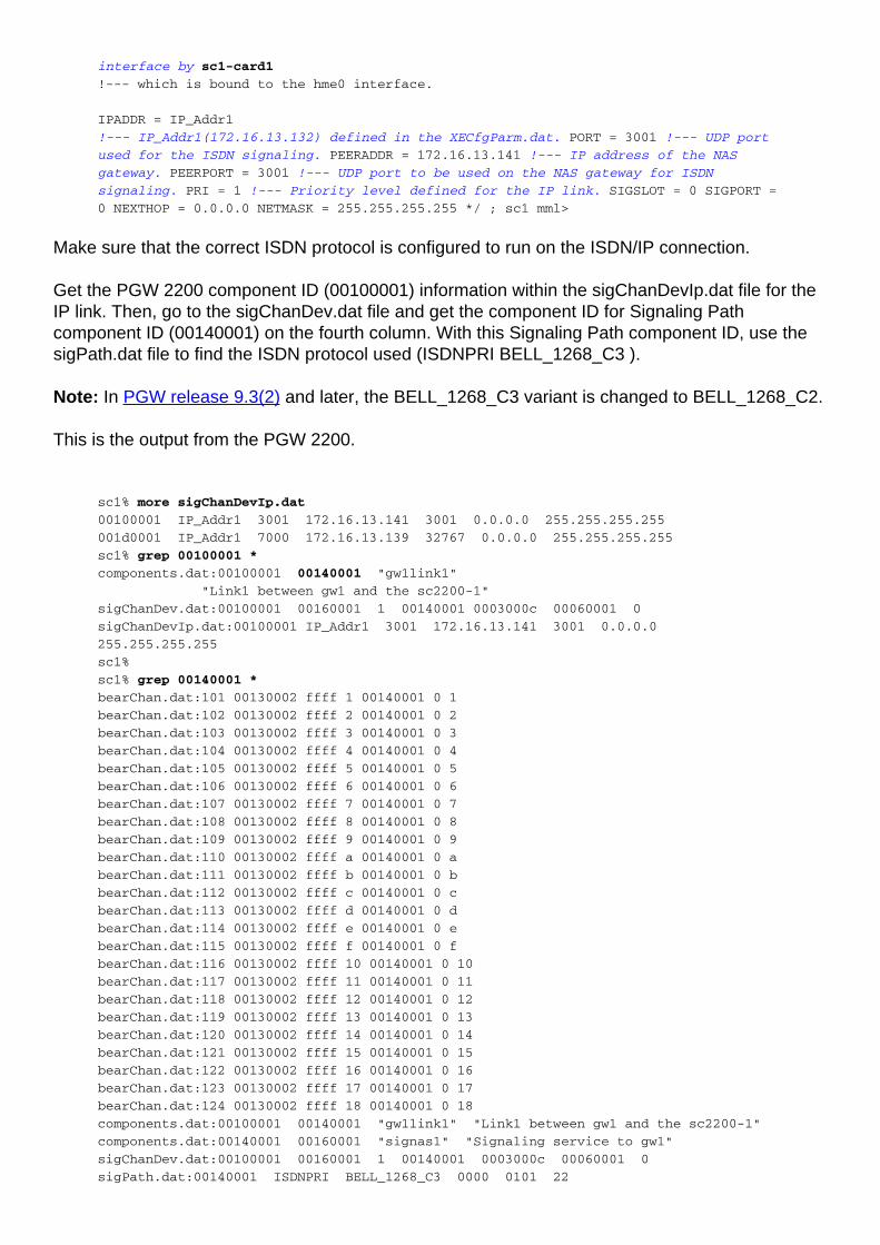
Make sure that the correct ISDN protocol is configured to run on the ISDN/IP connection.
Get the PGW 2200 component ID (00100001) information within the sigChanDevIp.dat file for theIP link. Then, go to the sigChanDev.dat file and get the component ID for Signaling Pathcomponent ID (00140001) on the fourth column. With this Signaling Path component ID, use thesigPath.dat file to find the ISDN protocol used (ISDNPRI BELL_1268_C3 ).
Note: In PGW release 9.3(2) and later, the BELL_1268_C3 variant is changed to BELL_1268_C2.
This is the output from the PGW 2200.
sc1% more sigChanDevIp.dat
00100001 IP_Addr1 3001 172.16.13.141 3001 0.0.0.0 255.255.255.255
001d0001 IP_Addr1 7000 172.16.13.139 32767 0.0.0.0 255.255.255.255
sc1% grep 00100001 *
components.dat:00100001 00140001 "gw1link1"
"Link1 between gw1 and the sc2200-1"
sigChanDev.dat:00100001 00160001 1 00140001 0003000c 00060001 0
sigChanDevIp.dat:00100001 IP_Addr1 3001 172.16.13.141 3001 0.0.0.0
255.255.255.255
sc1%
sc1% grep 00140001 *
bearChan.dat:101 00130002 ffff 1 00140001 0 1
bearChan.dat:102 00130002 ffff 2 00140001 0 2
bearChan.dat:103 00130002 ffff 3 00140001 0 3
bearChan.dat:104 00130002 ffff 4 00140001 0 4
bearChan.dat:105 00130002 ffff 5 00140001 0 5
bearChan.dat:106 00130002 ffff 6 00140001 0 6
bearChan.dat:107 00130002 ffff 7 00140001 0 7
bearChan.dat:108 00130002 ffff 8 00140001 0 8
bearChan.dat:109 00130002 ffff 9 00140001 0 9
bearChan.dat:110 00130002 ffff a 00140001 0 a
bearChan.dat:111 00130002 ffff b 00140001 0 b
bearChan.dat:112 00130002 ffff c 00140001 0 c
bearChan.dat:113 00130002 ffff d 00140001 0 d
bearChan.dat:114 00130002 ffff e 00140001 0 e
bearChan.dat:115 00130002 ffff f 00140001 0 f
bearChan.dat:116 00130002 ffff 10 00140001 0 10
bearChan.dat:117 00130002 ffff 11 00140001 0 11
bearChan.dat:118 00130002 ffff 12 00140001 0 12
bearChan.dat:119 00130002 ffff 13 00140001 0 13
bearChan.dat:120 00130002 ffff 14 00140001 0 14
bearChan.dat:121 00130002 ffff 15 00140001 0 15
bearChan.dat:122 00130002 ffff 16 00140001 0 16
bearChan.dat:123 00130002 ffff 17 00140001 0 17
bearChan.dat:124 00130002 ffff 18 00140001 0 18
components.dat:00100001 00140001 "gw1link1" "Link1 between gw1 and the sc2200-1"
components.dat:00140001 00160001 "signas1" "Signaling service to gw1"
sigChanDev.dat:00100001 00160001 1 00140001 0003000c 00060001 0
sigPath.dat:00140001 ISDNPRI BELL_1268_C3 0000 0101 22

network n 0 0 0 2 0000 N
sc1%
Notes:
00140001—Signalling Path Component ID.●
ISDNPRI—Value in order for ISDN over IP to work.●
BELL_1268_C3 0—Specifies Primary NI2 protocol type (must be this value for ISDN over IP).●
Note: In PGW release 9.3(2) and later, the BELL_1268_C3 variant is changed to BELL_1268_C2.
Refer to Configuration Data File Reference for more information on the Component and .dat files.
This is some reference information for the standby PGW 2200. Most of this information is in Out-Of-Service (OOS) standby mode.
sc3 mml>rtrv-ne
MGC-02 - Media Gateway Controller 2002-01-15 17:42:50
M RTRV
"Type:MGC"
"Hardware platform:sun4u sparc SUNW,Ultra-60"
"Vendor:"Cisco Systems, Inc.""
"Location:MGC-02 - Media Gateway Controller"
"Version:"7.4(11)""
"Platform State:STANDBY"
!--- The current state of the PGW 2200. ; sc3 mml>rtrv-softw:all
!--- Note the processes are running in STANDBY mode. MGC-02 - Media Gateway
Controller 2002-01-15 17:42:54 M RTRV "CFM-01:RUNNING STANDBY" "ALM-01:RUNNING
STANDBY" "MM-01:RUNNING STANDBY" "AMDMPR-01:RUNNING STANDBY" "CDRDMPR-01:RUNNING
STANDBY" "DSKM-01:RUNNING IN N/A STATE" "MMDB-01:RUNNING IN N/A STATE" "POM-
01:RUNNING STANDBY" "MEASAGT:RUNNING STANDBY" "OPERSAGT:RUNNING STANDBY"
"PROVSAGT:RUNNING STANDBY" "priip-1:RUNNING IN N/A STATE" "Replic-01:RUNNING STANDBY"
"ENG-01:RUNNING STANDBY" "IOCM-01:RUNNING STANDBY" "TCAP-01:RUNNING IN N/A STATE"
"ss7-a-1:RUNNING IN N/A STATE" "FOD-01:RUNNING IN N/A STATE" <Press Enter to continue
OR Press * and Enter to quit output of command> "LOG-01:RUNNING IN N/A STATE" ; sc3
mml> rtrv-sc:all
MGC-02 - Media Gateway Controller 2002-01-15 17:43:00
M RTRV
"GW1LINK1:SIGNAS1,LID=0:OOS,STBY"
/* Link1 between gw1 and the sc2200-1 */
"ls1-link1:ls1,LID=0:OOS,STBY"
/* Link1 for ls1 */
;
sc3 mml> rtrv-dest:all
MGC-02 - Media Gateway Controller 2002-01-15 17:43:04
M RTRV
"dpc-sc2200:PKG=SS7-ANSI,ASSOC=signas1,PST=IS,SST=RSTO"
"SIGNAS1:PKG=ISDNPRI,ASSOC=DPC-SC2200,PST=IS,SST=RSTO"
;
Troubleshoot
This section provides information you can use to troubleshoot your configuration.
Troubleshooting Commands
Certain show commands are supported by the Output Interpreter Tool (registered customers only), which allows you to view an analysis of show command output.
Note: Refer to Important Information on Debug Commands before you issue debug commands.
debug rlm group x—Displays information on the keepalive and packet flow between thePGW 2200 and the NAS gateway.
●
show access-list 199—Used to filter on traffic between the PGW 2200 and the NAS.●
debug ip packet 199 detail—Displays detailed IP debugging information.●
debug isdn q921—Displays data link Layer 2 access procedures taking place at the router onthe D-channel of the ISDN interface.
●
show debug—Displays debug information.●
show isdn status—Displays the status of all ISDN interfaces.●
show rlm group 0—Displays the status of the RLM.●
When you troubleshoot the communication between the NAS and the PGW 2200, there are twomain parts:
RLM signaling●
ISDN signaling●
Several problems that can cause RLM to be in the down state are:
Mis-configuration on the router or the PGW 2200.●
Physically, interfaces (Ethernet, Fast Ethernet, Serial x:23) are shutdown or have a bad cable.●
Access-lists that block communication between the two device IP address, UDP port 3000(RLM-mgr), and 3001 (ISDN).
●
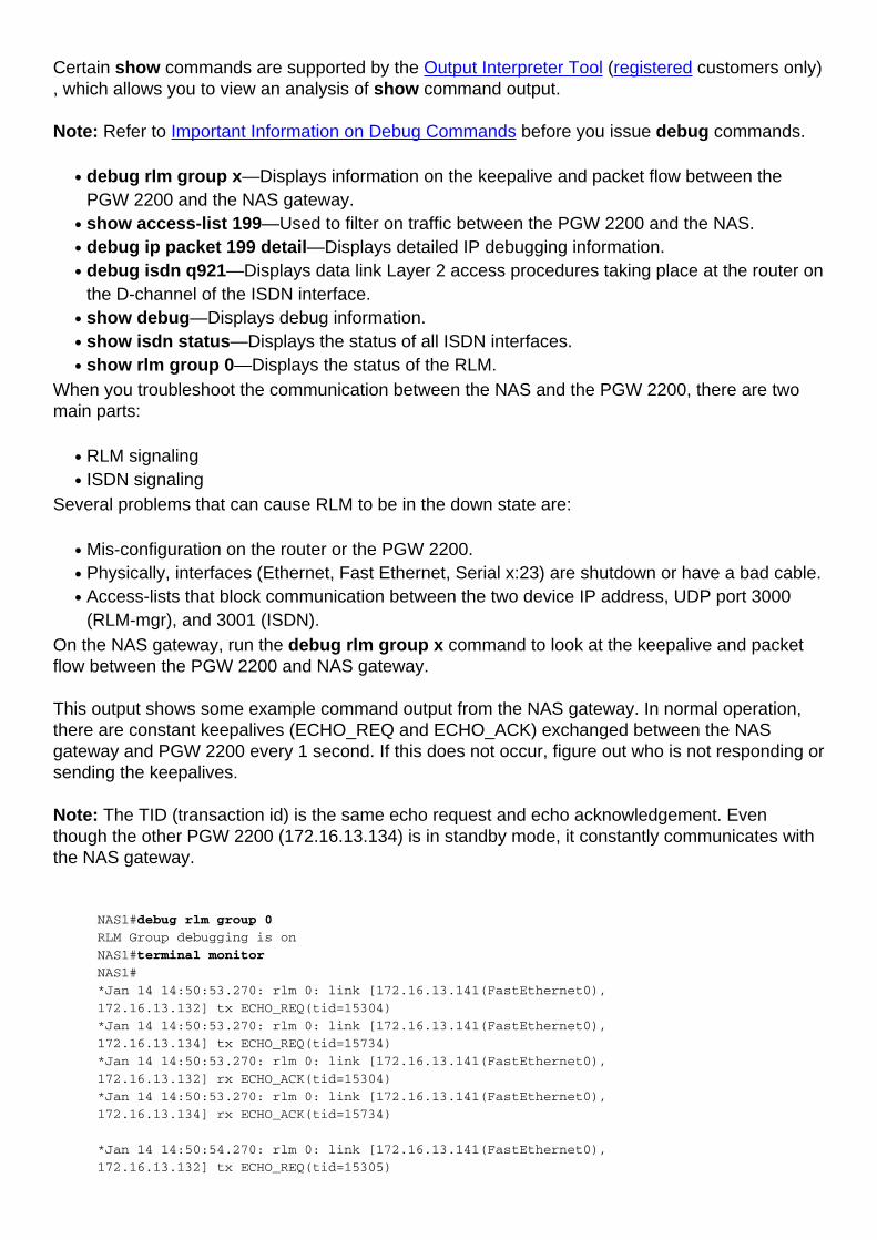
On the NAS gateway, run the debug rlm group x command to look at the keepalive and packetflow between the PGW 2200 and NAS gateway.
This output shows some example command output from the NAS gateway. In normal operation,there are constant keepalives (ECHO_REQ and ECHO_ACK) exchanged between the NASgateway and PGW 2200 every 1 second. If this does not occur, figure out who is not responding orsending the keepalives.
Note: The TID (transaction id) is the same echo request and echo acknowledgement. Eventhough the other PGW 2200 (172.16.13.134) is in standby mode, it constantly communicates withthe NAS gateway.
NAS1#debug rlm group 0
RLM Group debugging is on
NAS1#terminal monitor
NAS1#
*Jan 14 14:50:53.270: rlm 0: link [172.16.13.141(FastEthernet0),
172.16.13.132] tx ECHO_REQ(tid=15304)
*Jan 14 14:50:53.270: rlm 0: link [172.16.13.141(FastEthernet0),
172.16.13.134] tx ECHO_REQ(tid=15734)
*Jan 14 14:50:53.270: rlm 0: link [172.16.13.141(FastEthernet0),
172.16.13.132] rx ECHO_ACK(tid=15304)
*Jan 14 14:50:53.270: rlm 0: link [172.16.13.141(FastEthernet0),
172.16.13.134] rx ECHO_ACK(tid=15734)
*Jan 14 14:50:54.270: rlm 0: link [172.16.13.141(FastEthernet0),
172.16.13.132] tx ECHO_REQ(tid=15305)
*Jan 14 14:50:54.270: rlm 0: link [172.16.13.141(FastEthernet0),
172.16.13.134] tx ECHO_REQ(tid=15735)
*Jan 14 14:50:54.270: rlm 0: link [172.16.13.141(FastEthernet0),
172.16.13.132] rx ECHO_ACK(tid=15305)
*Jan 14 14:50:54.270: rlm 0: link [172.16.13.141(FastEthernet0),
172.16.13.134] rx ECHO_ACK(tid=15735)
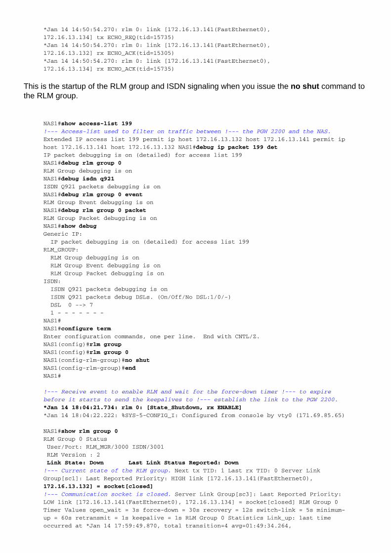
This is the startup of the RLM group and ISDN signaling when you issue the no shut command tothe RLM group.
NAS1#show access-list 199
!--- Access-list used to filter on traffic between !--- the PGW 2200 and the NAS.
Extended IP access list 199 permit ip host 172.16.13.132 host 172.16.13.141 permit ip
host 172.16.13.141 host 172.16.13.132 NAS1#debug ip packet 199 det
IP packet debugging is on (detailed) for access list 199
NAS1#debug rlm group 0
RLM Group debugging is on
NAS1#debug isdn q921
ISDN Q921 packets debugging is on
NAS1#debug rlm group 0 event
RLM Group Event debugging is on
NAS1#debug rlm group 0 packet
RLM Group Packet debugging is on
NAS1#show debug
Generic IP:
IP packet debugging is on (detailed) for access list 199
RLM_GROUP:
RLM Group debugging is on
RLM Group Event debugging is on
RLM Group Packet debugging is on
ISDN:
ISDN Q921 packets debugging is on
ISDN Q921 packets debug DSLs. (On/Off/No DSL:1/0/-)
DSL 0 --> 7
1 - - - - - - -
NAS1#
NAS1#configure term
Enter configuration commands, one per line. End with CNTL/Z.
NAS1(config)#rlm group
NAS1(config)#rlm group 0
NAS1(config-rlm-group)#no shut
NAS1(config-rlm-group)#end
NAS1#
!--- Receive event to enable RLM and wait for the force-down timer !--- to expire
before it starts to send the keepalives to !--- establish the link to the PGW 2200.
*Jan 14 18:04:21.734: rlm 0: [State_Shutdown, rx ENABLE]
*Jan 14 18:04:22.222: %SYS-5-CONFIG_I: Configured from console by vty0 (171.69.85.65)
NAS1#show rlm group 0
RLM Group 0 Status
User/Port: RLM_MGR/3000 ISDN/3001
RLM Version : 2
Link State: Down Last Link Status Reported: Down
!--- Current state of the RLM group. Next tx TID: 1 Last rx TID: 0 Server Link
Group[sc1]: Last Reported Priority: HIGH link [172.16.13.141(FastEthernet0),
172.16.13.132] = socket[closed]
!--- Communication socket is closed. Server Link Group[sc3]: Last Reported Priority:
LOW link [172.16.13.141(FastEthernet0), 172.16.13.134] = socket[closed] RLM Group 0
Timer Values open_wait = 3s force-down = 30s recovery = 12s switch-link = 5s minimum-
up = 60s retransmit = 1s keepalive = 1s RLM Group 0 Statistics Link_up: last time
occurred at *Jan 14 17:59:49.870, total transition=4 avg=01:49:34.264,

max=05:40:16.976, min=00:00:00.000, latest=00:02:08.728 Link_down: last time occurred
at *Jan 14 18:01:58.598, total transition=3 avg=00:08:27.002, max=00:16:18.004,
min=00:00:00.000, latest=00:16:18.004 Link_recovered: last time occurred at *Jan 14
12:03:14.887, success=2(100%), failure=0 avg=0.004s, max=0.004s, min=0.000s,
latest=0.004s Link_switched: last time occurred at none, success=0(0%), failure=0
avg=0.000s, max=0.000s, min=0.000s, latest=0.000s Server_changed: last time occurred
at *Jan 14 12:03:14.891 for totally 2 times Server Link Group[sc1]: Open the link
[172.16.13.141(FastEthernet0), 172.16.13.132]: last time occurred at *Jan 14
17:59:46.870, success=2(100%), failure=0 avg=1.502s, max=3.000s, min=0.000s,
latest=0.004s Echo over link [172.16.13.141(FastEthernet0), 172.16.13.132]: last time
occurred at *Jan 14 18:01:57.874, success=25581(99%), failure=35 avg=0.000s,
max=0.032s, min=0.000s, latest=0.000s Server Link Group[sc3]: Open the link
[172.16.13.141(FastEthernet0), 172.16.13.134]: last time occurred at *Jan 14
17:59:46.870, success=2(100%), failure=0 avg=1.502s, max=3.000s, min=0.000s,
latest=0.004s Echo over link [172.16.13.141(FastEthernet0), 172.16.13.134]: last time
occurred at *Jan 14 18:01:57.874, success=26182(99%), failure=40 avg=0.000s,
max=0.032s, min=0.000s, latest=0.000s NAS1#show isdn status
!--- ISDN status is always DOWN if RLM is not up and running. Global ISDN Switchtype
= primary-ni ISDN Serial0:23 interface rlm-group = 0 dsl 0, interface ISDN Switchtype
= primary-ni : Primary D-channel of nfas group 0 Layer 1 Status: DEACTIVATED
Layer 2 Status:
TEI = 0, Ces = 1, SAPI = 0, State = TEI_ASSIGNED
Layer 3 Status:
0 Active Layer 3 Call(s)
Active dsl 0 CCBs = 0
The Free Channel Mask: 0xFFFFFF
Total Allocated ISDN CCBs = 0
NAS1#
!--- Force-down timer expired and router starts to send out !--- the ECHO_REQ to the
PGW 2200 to establish the link. *Jan 14 18:04:51.734: rlm 0: [State_Down, rx
DOWN_MIN_TIMEOUT]
*Jan 14 18:04:51.734: rlm 0: link [172.16.13.141(FastEthernet0), 172.16.13.132] =
socket[172.16.13.141, 172.16.13.132]
!--- Open the RLM user socket for both the RLM !--- manager and ISDN signaling. !---
Router sends out ECHO_REQ (RLM keepalive) to !--- the PGW 2200 to start the
communication. *Jan 14 18:04:51.734: rlm 0: [State_Down, rx USER_SOCKET_OPENED] over
link [172.16.13.141(FastEthernet0), 172.16.13.132] for user RLM_MGR *Jan 14
18:04:51.734: rlm 0: link [172.16.13.141(FastEthernet0), 172.16.13.132] is opened
*Jan 14 18:04:51.734: rlm 0: link [172.16.13.141(FastEthernet0),
172.16.13.132] tx ECHO_REQ(tid=25616)
*Jan 14 18:04:51.734: IP: s=172.16.13.141 (local),
d=172.16.13.132 (FastEthernet0), len 36, sending
*Jan 14 18:04:51.734: UDP src=3000, dst=3000
*Jan 14 18:04:51.734: rlm 0: link [172.16.13.141(FastEthernet0),
172.16.13.132] =
socket[172.16.13.141, 172.16.13.132]
*Jan 14 18:04:51.734: rlm 0: [State_Down, rx USER_SOCKET_OPENED] over link
[172.16.13.141(FastEthernet0), 172.16.13.132] for user ISDN
!--- Same process for the standby PGW 2200. *Jan 14 18:04:51.734: rlm 0: link
[172.16.13.141(FastEthernet0), 172.16.13.134] = socket[172.16.13.141, 172.16.13.134]
*Jan 14 18:04:51.734: rlm 0: [State_Down, rx USER_SOCKET_OPENED] over link
[172.16.13.141(FastEthernet0), 172.16.13.134] for user RLM_MGR *Jan 14 18:04:51.734:
rlm 0: link [172.16.13.141(FastEthernet0), 172.16.13.134] is opened *Jan 14
18:04:51.734: rlm 0: link [172.16.13.141(FastEthernet0), 172.16.13.134] tx
ECHO_REQ(tid=26222)
*Jan 14 18:04:51.738: rlm 0: link [172.16.13.141(FastEthernet0),
172.16.13.134] = socket[172.16.13.141, 172.16.13.134]
*Jan 14 18:04:51.738: rlm 0: [State_Down, rx USER_SOCKET_OPENED] over link
[172.16.13.141(FastEthernet0), 172.16.13.134] for user ISDN
*Jan 14 18:04:51.738: IP: s=172.16.13.132 (FastEthernet0), d=172.16.13.141
(FastEthernet0), len 36, rcvd 3
*Jan 14 18:04:51.738: UDP src=3000, dst=3000
!--- Recevied the ECHO_ACK back from the active and !--- standby PGW 2200. *Jan 14
18:04:51.738: rlm 0: link [172.16.13.141(FastEthernet0), 172.16.13.132] rx
ECHO_ACK(tid=25616)
*Jan 14 18:04:51.738: rlm 0: [State_Down, rx LINK_OPENED] over link
[172.16.13.141(FastEthernet0), 172.16.13.132]
*Jan 14 18:04:51.738: rlm 0: link [172.16.13.141(FastEthernet0),
172.16.13.134] rx ECHO_ACK(tid=26222)
*Jan 14 18:04:51.738: rlm 0: [State_Down, rx LINK_OPENED] over link
[172.16.13.141(FastEthernet0), 172.16.13.134]
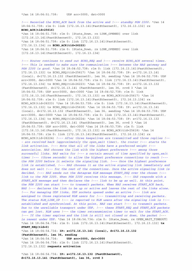
!--- Router continues to send out ECHO_REQ and !--- receive ECHO_ACK several times.
!--- This is needed to make sure the communication !--- between the NAS gateway and
PGW 2200 is good. *Jan 14 18:04:52.738: rlm 0: link [172.16.13.141(FastEthernet0),
172.16.13.132] tx ECHO_REQ(tid=25617) *Jan 14 18:04:52.738: IP: s=172.16.13.141
(local), d=172.16.13.132 (FastEthernet0), len 36, sending *Jan 14 18:04:52.738: UDP
src=3000, dst=3000 *Jan 14 18:04:52.738: rlm 0: link [172.16.13.141(FastEthernet0),
172.16.13.134] tx ECHO_REQ(tid=26223) *Jan 14 18:04:52.738: IP: s=172.16.13.132
(FastEthernet0), d=172.16.13.141 (FastEthernet0), len 36, rcvd 3 *Jan 14
18:04:52.738: UDP src=3000, dst=3000 *Jan 14 18:04:52.738: rlm 0: link
[172.16.13.141(FastEthernet0), 172.16.13.132] rx ECHO_ACK(tid=25617) *Jan 14
18:04:52.738: rlm 0: link [172.16.13.141(FastEthernet0), 172.16.13.134] rx
ECHO_ACK(tid=26223) *Jan 14 18:04:53.738: rlm 0: link [172.16.13.141(FastEthernet0),
172.16.13.132] tx ECHO_REQ(tid=25618) *Jan 14 18:04:53.738: IP: s=172.16.13.141
(local), d=172.16.13.132 (FastEthernet0), len 36, sending *Jan 14 18:04:53.738: UDP
src=3000, dst=3000 *Jan 14 18:04:53.738: rlm 0: link [172.16.13.141(FastEthernet0),
172.16.13.134] tx ECHO_REQ(tid=26224) *Jan 14 18:04:53.738: IP: s=172.16.13.132
(FastEthernet0), d=172.16.13.141 (FastEthernet0), len 36, rcvd 3 *Jan 14
18:04:53.738: UDP src=3000, dst=3000 *Jan 14 18:04:53.738: rlm 0: link
[172.16.13.141(FastEthernet0), 172.16.13.132] rx ECHO_ACK(tid=25618) *Jan 14
18:04:53.738: rlm 0: link [172.16.13.141(FastEthernet0), 172.16.13.134] rx
ECHO_ACK(tid=26224) !--- After three keepalives are transmitted and three replies !--
- are received back (approximately the open_wait timer), the router !--- starts the
link activation. !--- Note that all of the links have a preferred weight !---
association. NAS chooses the link with the highest preference !--- among those
successful links. NAS waits for !--- a certain amount of time specified by open_wait
timer !--- (three seconds) to allow the highest preference connections to reach !---
the PGW 2200 before it selects the signaling link. !--- Once the highest preference
link is established, !--- NAS chooses it as the active signaling link immediately and
does not wait !--- for the rest of the connections. Once the active signaling link is
decided, !--- NAS sends out the datagram RLM message START_REQ over the chosen !---
link to the PGW 2200. When PGW 2200 receives this message, !--- SAS responds with a
START_ACK message and then declares the !--- link to be up as well. At this point,
the PGW 2200 can start !--- to transmit packets. When NAS receives START_ACK back,
NAS !--- declares the link to be up or active and leaves the rest of the links alone.
!--- For managing UDP links, UDP sockets opened under an active !--- link are
assigned to those registered RLM users for !--- transmitting and receiving packets.
The status RLM_LINK_UP !--- is reported to RLM users after the signaling link is !---
established and synchronized. At this point, NAS can start !--- to transmit packets.
Due to the unreliable transport under UDP, !--- these START_REQ and START_ACK packets
can get lost. RLM uses !--- the timer retransmission timer to wait for the START_ACK.
!--- If the timer expires and the link is still not closed or down, the packet !---
is resent under UDP. *Jan 14 18:04:54.734: rlm 0: [State_Down, rx OPEN_WAIT_TIMEOUT]
*Jan 14 18:04:54.734: rlm 0: link [172.16.13.141(FastEthernet0), 172.16.13.132] tx
START_REQ(tid=0)
*Jan 14 18:04:54.734: IP: s=172.16.13.141 (local), d=172.16.13.132
(FastEthernet0), len 36, sending
*Jan 14 18:04:54.734: UDP src=3000, dst=3000
*Jan 14 18:04:54.734: rlm 0: link [172.16.13.141(FastEthernet0),
172.16.13.132] requests activation
*Jan 14 18:04:54.734: IP: s=172.16.13.132 (FastEthernet0),
d=172.16.13.141 (FastEthernet0), len 36, rcvd 3

*Jan 14 18:04:54.734: UDP src=3000, dst=3000
!--- RLM manager UDP port. *Jan 14 18:04:54.734: IP: s=172.16.13.132 (FastEthernet0),
d=172.16.13.141
(FastEthernet0), len 31, rcvd 3
*Jan 14 18:04:54.734: UDP src=3001, dst=3001
!--- ISDN signaling UDP port. *Jan 14 18:04:54.734: rlm 0: link
[172.16.13.141(FastEthernet0), 172.16.13.132] rx START_ACK(tid=0)
*Jan 14 18:04:54.734: rlm 0: [State_Down, rx START_ACK] over link
[172.16.13.141(FastEthernet0), 172.16.13.132]
*Jan 14 18:04:54.734: %ISDN-4-RLM_STATUS_CHANGE: ISDN SC Se0:23
SC: Status Changed to: Link Up.
*Jan 14 18:04:54.734: rlm 0: link [172.16.13.141(FastEthernet0),
172.16.13.132] is activated
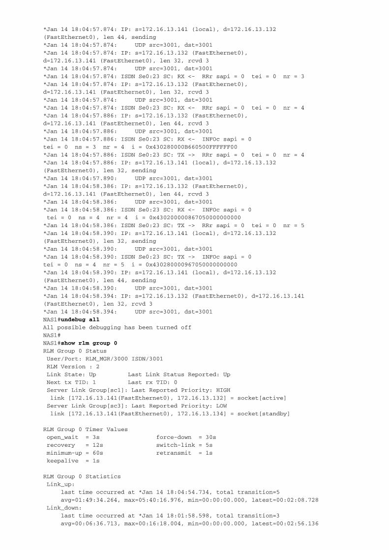
!--- The router starts to establish the ISDN signaling !--- with the PGW 2200. Note,
the NAS gateway sends the !--- signaling packet across the FastEthernet interface
using UDP !--- port 3001. Once both sides have received the !--- Unnumbered
Acknowledge (UA) frame from each other, ISDN Layer 2 status !--- moves from the
TEI_ASSIGNED state to the MULTIPLE_FRAME_ESTABLISHED state. !--- Next, normal ISDN
keepalives (RRf and RRp) are being exchanged between !--- the PGW 2200 and the NAS
gateway. *Jan 14 18:04:54.738: ISDN Se0:23 SC: RX <- SABMEp c/r = 1 sapi = 0 tei =
0
*Jan 14 18:04:54.738: %ISDN-6-LAYER2UP: Layer 2 for
Interface Se0:23 SC, TEI 0 changed to up
*Jan 14 18:04:54.738: ISDN Se0:23 SC:
TX -> SABMEp c/r = 0 sapi = 0 tei = 0
*Jan 14 18:04:54.738: IP: s=172.16.13.141 (local), d=172.16.13.132
(FastEthernet0), len 31, sending
*Jan 14 18:04:54.738: UDP src=3001, dst=3001
*Jan 14 18:04:54.742:
ISDN Se0:23 SC: TX -> UAf c/r = 1 sapi = 0 tei = 0
*Jan 14 18:04:54.742: IP: s=172.16.13.141 (local), d=172.16.13.132
(FastEthernet0), len 31, sending
*Jan 14 18:04:54.742: UDP src=3001, dst=3001
*Jan 14 18:04:54.742: ISDN Se0:23 SC: TX -> INFOc sapi = 0 tei = 0
ns = 0 nr = 0 i = 0x430200000A6808C000000000000000
*Jan 14 18:04:54.742: IP: s=172.16.13.141 (local), d=172.16.13.132
(FastEthernet0), len 47, sending
*Jan 14 18:04:54.742: UDP src=3001, dst=3001
*Jan 14 18:04:54.742: rlm 0: link [172.16.13.141(FastEthernet0),
172.16.13.134] tx ECHO_REQ(tid=26225)
*Jan 14 18:04:54.742: IP: s=172.16.13.132 (FastEthernet0), d=172.16.13.141
(FastEthernet0), len 31, rcvd 3
*Jan 14 18:04:54.742: UDP src=3001, dst=3001
*Jan 14 18:04:54.742: IP: s=172.16.13.132 (FastEthernet0), d=172.16.13.141
(FastEthernet0), len 32, rcvd 3
*Jan 14 18:04:54.746: UDP src=3001, dst=3001
*Jan 14 18:04:54.746: ISDN Se0:23 SC: TX -> INFOc sapi = 0 tei = 0
ns = 1 nr = 0 i = 0x430200000A6808C000000000000000
*Jan 14 18:04:54.746: IP: s=172.16.13.141 (local), d=172.16.13.132
(FastEthernet0), len 47, sending
*Jan 14 18:04:54.746: UDP src=3001, dst=3001
*Jan 14 18:04:54.746: rlm 0: link [172.16.13.141(FastEthernet0), 172.16.13.134]
rx ECHO_ACK(tid=26225)
*Jan 14 18:04:54.746: ISDN Se0:23 SC: RX <- UAf c/r = 0 sapi = 0 tei = 0
*Jan 14 18:04:54.746: ISDN Se0:23 SC: RX <- RRr sapi = 0 tei = 0 nr = 1
*Jan 14 18:04:54.750: IP: s=172.16.13.132 (FastEthernet0), d=172.16.13.141
(FastEthernet0), len 32, rcvd 3
*Jan 14 18:04:54.750: UDP src=3001, dst=3001
*Jan 14 18:04:54.750: ISDN Se0:23 SC: RX <- RRr sapi = 0 tei = 0 nr = 2
*Jan 14 18:04:54.754: IP: s=172.16.13.132 (FastEthernet0), d=172.16.13.141
(FastEthernet0), len 41, rcvd 3
*Jan 14 18:04:54.754: UDP src=3001, dst=3001
*Jan 14 18:04:54.758: ISDN Se0:23 SC: RX <- INFOc sapi = 0 tei = 0 ns = 0

nr = 2 i = 0x430280005A080283A9
*Jan 14 18:04:54.758: ISDN Se0:23 SC: TX -> RRr sapi = 0 tei = 0 nr = 1
*Jan 14 18:04:54.758: IP: s=172.16.13.141 (local), d=172.16.13.132
(FastEthernet0), len 32, sending
*Jan 14 18:04:54.758: UDP src=3001, dst=3001
*Jan 14 18:04:54.766: IP: s=172.16.13.132 (FastEthernet0), d=172.16.13.141
(FastEthernet0), len 41, rcvd 3
*Jan 14 18:04:54.766: UDP src=3001, dst=3001
*Jan 14 18:04:54.766: ISDN Se0:23 SC: RX <- INFOc sapi = 0 tei = 0
ns = 1 nr = 2 i = 0x430280005A080283A9
*Jan 14 18:04:54.766: ISDN Se0:23 SC: TX -> RRr sapi = 0 tei = 0 nr = 2
*Jan 14 18:04:54.766: IP: s=172.16.13.141 (local), d=172.16.13.132
(FastEthernet0), len 32, sending
*Jan 14 18:04:54.770: UDP src=3001, dst=3001
*Jan 14 18:04:55.742: rlm 0: link [172.16.13.141(FastEthernet0),
172.16.13.134] tx ECHO_REQ(tid=26226)
*Jan 14 18:04:55.742: rlm 0: link [172.16.13.141(FastEthernet0),
172.16.13.134] rx ECHO_ACK(tid=26226)
*Jan 14 18:04:56.734: %LINK-3-UPDOWN: Interface Serial0:23,
changed state to up
*Jan 14 18:04:56.742: rlm 0: link [172.16.13.141(FastEthernet0),
172.16.13.132] tx ECHO_REQ(tid=25619)
*Jan 14 18:04:56.742: IP: s=172.16.13.141 (local), d=172.16.13.132
(FastEthernet0), len 36, sending
*Jan 14 18:04:56.742: UDP src=3000, dst=3000
*Jan 14 18:04:56.742: rlm 0: link [172.16.13.141(FastEthernet0),
172.16.13.134] tx ECHO_REQ(tid=26227)
*Jan 14 18:04:56.742: IP: s=172.16.13.132 (FastEthernet0), d=172.16.13.141
(FastEthernet0), len 36, rcvd 3
*Jan 14 18:04:56.742: UDP src=3000, dst=3000
*Jan 14 18:04:56.742: rlm 0: link [172.16.13.141(FastEthernet0),
172.16.13.132] rx ECHO_ACK(tid=25619)
*Jan 14 18:04:56.742: rlm 0: link [172.16.13.141(FastEthernet0),
172.16.13.134] rx ECHO_ACK(tid=26227)
*Jan 14 18:04:57.742: rlm 0: link [172.16.13.141(FastEthernet0),
172.16.13.132] tx ECHO_REQ(tid=25620)
*Jan 14 18:04:57.742: IP: s=172.16.13.141 (local), d=172.16.13.132
(FastEthernet0), len 36, sending
*Jan 14 18:04:57.742: UDP src=3000, dst=3000
*Jan 14 18:04:57.742: rlm 0: link [172.16.13.141(FastEthernet0),
172.16.13.134] tx ECHO_REQ(tid=26228)
*Jan 14 18:04:57.742: IP: s=172.16.13.132 (FastEthernet0), d=172.16.13.141
(FastEthernet0), len 36, rcvd 3
*Jan 14 18:04:57.742: UDP src=3000, dst=3000
*Jan 14 18:04:57.742: rlm 0: link [172.16.13.141(FastEthernet0),
172.16.13.132] rx ECHO_ACK(tid=25620)
*Jan 14 18:04:57.742: rlm 0: link [172.16.13.141(FastEthernet0),
172.16.13.134] rx ECHO_ACK(tid=26228)
*Jan 14 18:04:57.866: IP: s=172.16.13.132 (FastEthernet0), d=172.16.13.141
(FastEthernet0), len 47, rcvd 3
*Jan 14 18:04:57.866: UDP src=3001, dst=3001
*Jan 14 18:04:57.866: ISDN Se0:23 SC: RX <- INFOc sapi = 0 tei = 0
ns = 2 nr = 2 i = 0x430200000A6808C000000000000000
*Jan 14 18:04:57.866: ISDN Se0:23 SC: TX -> RRr sapi = 0 tei = 0 nr = 3
*Jan 14 18:04:57.870: IP: s=172.16.13.141 (local), d=172.16.13.132
(FastEthernet0), len 32, sending
*Jan 14 18:04:57.870: UDP src=3001, dst=3001
*Jan 14 18:04:57.870: ISDN Se0:23 SC: TX -> INFOc sapi = 0 tei = 0
ns = 2 nr = 3 i = 0x430280000A6808C000000000000000
*Jan 14 18:04:57.870: IP: s=172.16.13.141 (local), d=172.16.13.132
(FastEthernet0), len 47, sending
*Jan 14 18:04:57.870: UDP src=3001, dst=3001
*Jan 14 18:04:57.870: ISDN Se0:23 SC: TX -> INFOc sapi = 0 tei = 0
ns = 3 nr = 3 i = 0x4302000006660500FFFFFF00
*Jan 14 18:04:57.874: IP: s=172.16.13.141 (local), d=172.16.13.132
(FastEthernet0), len 44, sending
*Jan 14 18:04:57.874: UDP src=3001, dst=3001
*Jan 14 18:04:57.874: IP: s=172.16.13.132 (FastEthernet0),
d=172.16.13.141 (FastEthernet0), len 32, rcvd 3
*Jan 14 18:04:57.874: UDP src=3001, dst=3001
*Jan 14 18:04:57.874: ISDN Se0:23 SC: RX <- RRr sapi = 0 tei = 0 nr = 3
*Jan 14 18:04:57.874: IP: s=172.16.13.132 (FastEthernet0),
d=172.16.13.141 (FastEthernet0), len 32, rcvd 3
*Jan 14 18:04:57.874: UDP src=3001, dst=3001
*Jan 14 18:04:57.874: ISDN Se0:23 SC: RX <- RRr sapi = 0 tei = 0 nr = 4
*Jan 14 18:04:57.886: IP: s=172.16.13.132 (FastEthernet0),
d=172.16.13.141 (FastEthernet0), len 44, rcvd 3
*Jan 14 18:04:57.886: UDP src=3001, dst=3001
*Jan 14 18:04:57.886: ISDN Se0:23 SC: RX <- INFOc sapi = 0
tei = 0 ns = 3 nr = 4 i = 0x430280000B660500FFFFFF00
*Jan 14 18:04:57.886: ISDN Se0:23 SC: TX -> RRr sapi = 0 tei = 0 nr = 4
*Jan 14 18:04:57.886: IP: s=172.16.13.141 (local), d=172.16.13.132
(FastEthernet0), len 32, sending
*Jan 14 18:04:57.890: UDP src=3001, dst=3001
*Jan 14 18:04:58.386: IP: s=172.16.13.132 (FastEthernet0),
d=172.16.13.141 (FastEthernet0), len 44, rcvd 3
*Jan 14 18:04:58.386: UDP src=3001, dst=3001
*Jan 14 18:04:58.386: ISDN Se0:23 SC: RX <- INFOc sapi = 0
tei = 0 ns = 4 nr = 4 i = 0x430200000867050000000000
*Jan 14 18:04:58.386: ISDN Se0:23 SC: TX -> RRr sapi = 0 tei = 0 nr = 5
*Jan 14 18:04:58.390: IP: s=172.16.13.141 (local), d=172.16.13.132
(FastEthernet0), len 32, sending
*Jan 14 18:04:58.390: UDP src=3001, dst=3001
*Jan 14 18:04:58.390: ISDN Se0:23 SC: TX -> INFOc sapi = 0
tei = 0 ns = 4 nr = 5 i = 0x430280000967050000000000
*Jan 14 18:04:58.390: IP: s=172.16.13.141 (local), d=172.16.13.132
(FastEthernet0), len 44, sending
*Jan 14 18:04:58.390: UDP src=3001, dst=3001
*Jan 14 18:04:58.394: IP: s=172.16.13.132 (FastEthernet0), d=172.16.13.141
(FastEthernet0), len 32, rcvd 3
*Jan 14 18:04:58.394: UDP src=3001, dst=3001
NAS1#undebug all
All possible debugging has been turned off
NAS1#
NAS1#show rlm group 0
RLM Group 0 Status
User/Port: RLM_MGR/3000 ISDN/3001
RLM Version : 2
Link State: Up Last Link Status Reported: Up
Next tx TID: 1 Last rx TID: 0
Server Link Group[sc1]: Last Reported Priority: HIGH
link [172.16.13.141(FastEthernet0), 172.16.13.132] = socket[active]
Server Link Group[sc3]: Last Reported Priority: LOW
link [172.16.13.141(FastEthernet0), 172.16.13.134] = socket[standby]
RLM Group 0 Timer Values
open_wait = 3s force-down = 30s
recovery = 12s switch-link = 5s
minimum-up = 60s retransmit = 1s
keepalive = 1s
RLM Group 0 Statistics
Link_up:
last time occurred at *Jan 14 18:04:54.734, total transition=5
avg=01:49:34.264, max=05:40:16.976, min=00:00:00.000, latest=00:02:08.728
Link_down:
last time occurred at *Jan 14 18:01:58.598, total transition=3
avg=00:06:36.713, max=00:16:18.004, min=00:00:00.000, latest=00:02:56.136
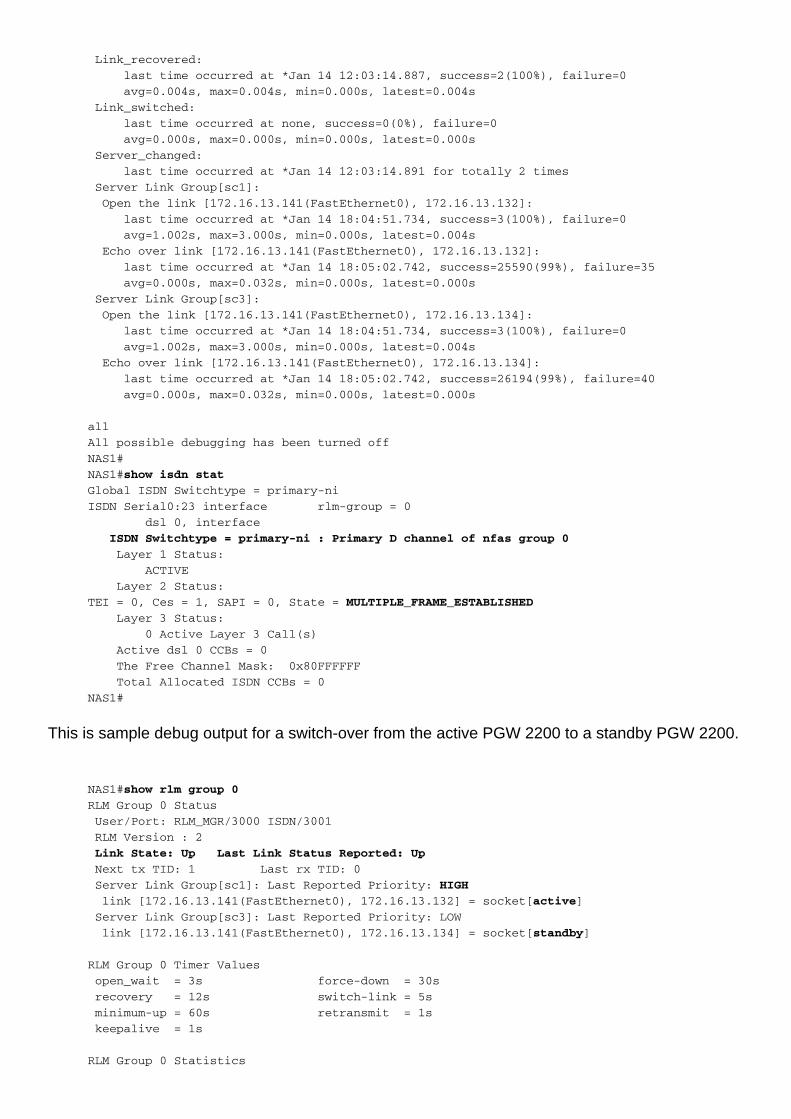
Link_recovered:
last time occurred at *Jan 14 12:03:14.887, success=2(100%), failure=0
avg=0.004s, max=0.004s, min=0.000s, latest=0.004s
Link_switched:
last time occurred at none, success=0(0%), failure=0
avg=0.000s, max=0.000s, min=0.000s, latest=0.000s
Server_changed:
last time occurred at *Jan 14 12:03:14.891 for totally 2 times
Server Link Group[sc1]:
Open the link [172.16.13.141(FastEthernet0), 172.16.13.132]:
last time occurred at *Jan 14 18:04:51.734, success=3(100%), failure=0
avg=1.002s, max=3.000s, min=0.000s, latest=0.004s
Echo over link [172.16.13.141(FastEthernet0), 172.16.13.132]:
last time occurred at *Jan 14 18:05:02.742, success=25590(99%), failure=35
avg=0.000s, max=0.032s, min=0.000s, latest=0.000s
Server Link Group[sc3]:
Open the link [172.16.13.141(FastEthernet0), 172.16.13.134]:
last time occurred at *Jan 14 18:04:51.734, success=3(100%), failure=0
avg=1.002s, max=3.000s, min=0.000s, latest=0.004s
Echo over link [172.16.13.141(FastEthernet0), 172.16.13.134]:
last time occurred at *Jan 14 18:05:02.742, success=26194(99%), failure=40
avg=0.000s, max=0.032s, min=0.000s, latest=0.000s
all
All possible debugging has been turned off
NAS1#
NAS1#show isdn stat
Global ISDN Switchtype = primary-ni
ISDN Serial0:23 interface rlm-group = 0
dsl 0, interface
ISDN Switchtype = primary-ni : Primary D channel of nfas group 0
Layer 1 Status:
ACTIVE
Layer 2 Status:
TEI = 0, Ces = 1, SAPI = 0, State = MULTIPLE_FRAME_ESTABLISHED
Layer 3 Status:
0 Active Layer 3 Call(s)
Active dsl 0 CCBs = 0
The Free Channel Mask: 0x80FFFFFF
Total Allocated ISDN CCBs = 0
NAS1#
This is sample debug output for a switch-over from the active PGW 2200 to a standby PGW 2200.
NAS1#show rlm group 0
RLM Group 0 Status
User/Port: RLM_MGR/3000 ISDN/3001
RLM Version : 2
Link State: Up Last Link Status Reported: Up
Next tx TID: 1 Last rx TID: 0
Server Link Group[sc1]: Last Reported Priority: HIGH
link [172.16.13.141(FastEthernet0), 172.16.13.132] = socket[active]
Server Link Group[sc3]: Last Reported Priority: LOW
link [172.16.13.141(FastEthernet0), 172.16.13.134] = socket[standby]
RLM Group 0 Timer Values
open_wait = 3s force-down = 30s
recovery = 12s switch-link = 5s
minimum-up = 60s retransmit = 1s
keepalive = 1s
RLM Group 0 Statistics
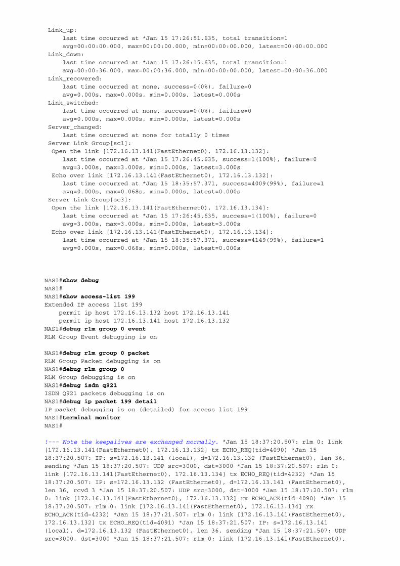
Link_up:
last time occurred at *Jan 15 17:26:51.635, total transition=1
avg=00:00:00.000, max=00:00:00.000, min=00:00:00.000, latest=00:00:00.000
Link_down:
last time occurred at *Jan 15 17:26:15.635, total transition=1
avg=00:00:36.000, max=00:00:36.000, min=00:00:00.000, latest=00:00:36.000
Link_recovered:
last time occurred at none, success=0(0%), failure=0
avg=0.000s, max=0.000s, min=0.000s, latest=0.000s
Link_switched:
last time occurred at none, success=0(0%), failure=0
avg=0.000s, max=0.000s, min=0.000s, latest=0.000s
Server_changed:
last time occurred at none for totally 0 times
Server Link Group[sc1]:
Open the link [172.16.13.141(FastEthernet0), 172.16.13.132]:
last time occurred at *Jan 15 17:26:45.635, success=1(100%), failure=0
avg=3.000s, max=3.000s, min=0.000s, latest=3.000s
Echo over link [172.16.13.141(FastEthernet0), 172.16.13.132]:
last time occurred at *Jan 15 18:35:57.371, success=4009(99%), failure=1
avg=0.000s, max=0.068s, min=0.000s, latest=0.000s
Server Link Group[sc3]:
Open the link [172.16.13.141(FastEthernet0), 172.16.13.134]:
last time occurred at *Jan 15 17:26:45.635, success=1(100%), failure=0
avg=3.000s, max=3.000s, min=0.000s, latest=3.000s
Echo over link [172.16.13.141(FastEthernet0), 172.16.13.134]:
last time occurred at *Jan 15 18:35:57.371, success=4149(99%), failure=1
avg=0.000s, max=0.068s, min=0.000s, latest=0.000s
NAS1#show debug
NAS1#
NAS1#show access-list 199
Extended IP access list 199
permit ip host 172.16.13.132 host 172.16.13.141
permit ip host 172.16.13.141 host 172.16.13.132
NAS1#debug rlm group 0 event
RLM Group Event debugging is on
NAS1#debug rlm group 0 packet
RLM Group Packet debugging is on
NAS1#debug rlm group 0
RLM Group debugging is on
NAS1#debug isdn q921
ISDN Q921 packets debugging is on
NAS1#debug ip packet 199 detail
IP packet debugging is on (detailed) for access list 199
NAS1#terminal monitor
NAS1#
!--- Note the keepalives are exchanged normally. *Jan 15 18:37:20.507: rlm 0: link
[172.16.13.141(FastEthernet0), 172.16.13.132] tx ECHO_REQ(tid=4090) *Jan 15
18:37:20.507: IP: s=172.16.13.141 (local), d=172.16.13.132 (FastEthernet0), len 36,
sending *Jan 15 18:37:20.507: UDP src=3000, dst=3000 *Jan 15 18:37:20.507: rlm 0:
link [172.16.13.141(FastEthernet0), 172.16.13.134] tx ECHO_REQ(tid=4232) *Jan 15
18:37:20.507: IP: s=172.16.13.132 (FastEthernet0), d=172.16.13.141 (FastEthernet0),
len 36, rcvd 3 *Jan 15 18:37:20.507: UDP src=3000, dst=3000 *Jan 15 18:37:20.507: rlm
0: link [172.16.13.141(FastEthernet0), 172.16.13.132] rx ECHO_ACK(tid=4090) *Jan 15
18:37:20.507: rlm 0: link [172.16.13.141(FastEthernet0), 172.16.13.134] rx
ECHO_ACK(tid=4232) *Jan 15 18:37:21.507: rlm 0: link [172.16.13.141(FastEthernet0),
172.16.13.132] tx ECHO_REQ(tid=4091) *Jan 15 18:37:21.507: IP: s=172.16.13.141
(local), d=172.16.13.132 (FastEthernet0), len 36, sending *Jan 15 18:37:21.507: UDP
src=3000, dst=3000 *Jan 15 18:37:21.507: rlm 0: link [172.16.13.141(FastEthernet0),

172.16.13.134] tx ECHO_REQ(tid=4233) *Jan 15 18:37:21.511: rlm 0: link
[172.16.13.141(FastEthernet0), 172.16.13.134] rx ECHO_ACK(tid=4233) !--- Note: The
NAS gateway receives
!--- an ECHO_REQ from the PGW 2200
!--- when the switch-over occurs. Within the packet, there is a change in the
!--- priority setting and the NAS gateway is informed to re-establish the link to
!--- the new active PGW 2200 (172.16.13.134).
*Jan 15 18:37:21.763: rlm 0: link [172.16.13.141(FastEthernet0),
172.16.13.134] rx ECHO_REQ(tid=1)
*Jan 15 18:37:21.763: rlm 0: link [172.16.13.141(FastEthernet0),
172.16.13.134] tx ECHO_ACK(tid=1)
*Jan 15 18:37:21.763: rlm 0 server : sc3 changing priority from LOW to HIGH
*Jan 15 18:37:21.763: rlm 0: [State_Up, rx NEW_LINK_WEIGHTING] over
link [172.16.13.141(FastEthernet0), 172.16.13.134]
*Jan 15 18:37:21.763: rlm 0 Link ordering : New Server sc3
*Jan 15 18:37:21.763: rlm 0 Link ordering : Current Server sc1
!--- The NAS gateway starts the link activation !--- toward the new active PGW 2200
and becomes active. The other !--- link is deactivated and goes into standby. *Jan 15
18:37:21.763: rlm 0: link [172.16.13.141(FastEthernet0), 172.16.13.134] tx
START_REQ(tid=1)
*Jan 15 18:37:21.763: rlm 0: link [172.16.13.141(FastEthernet0),
172.16.13.134] requests activation
*Jan 15 18:37:21.767: rlm 0: link [172.16.13.141(FastEthernet0),
172.16.13.134] rx START_ACK(tid=1)
*Jan 15 18:37:21.767: rlm 0: [State_Recover, rx START_ACK] over link
[172.16.13.141(FastEthernet0), 172.16.13.134]
*Jan 15 18:37:21.767: rlm 0: link [172.16.13.141(FastEthernet0),
172.16.13.132] is deactivated
*Jan 15 18:37:21.767: %ISDN-4-RLM_STATUS_CHANGE: ISDN SC Se0:23
SC: Status Changed to: Server Switched.
*Jan 15 18:37:21.767: rlm 0: link [172.16.13.141(FastEthernet0),
172.16.13.134] is activated
*Jan 15 18:37:21.767: ISDN Se0:23 SC: TX -> INFOc sapi = 0 tei = 0
ns = 4 nr = 4 i = 0x430200000A6808C000000000000000
!--- The NAS gateway needs to re-establish the ISDN !--- signaling with the new
active PGW 2200. *Jan 15 18:37:21.771: ISDN Se0:23 SC: RX <- SABMEp c/r = 1 sapi = 0
tei = 0
*Jan 15 18:37:22.519: rlm 0: link [172.16.13.141(FastEthernet0),
172.16.13.132] tx ECHO_REQ(tid=4092)
*Jan 15 18:37:22.519: IP: s=172.16.13.141 (local), d=172.16.13.132
(FastEthernet0), len 36, sending
*Jan 15 18:37:22.519: UDP src=3000, dst=3000
*Jan 15 18:37:22.523: IP: s=172.16.13.132 (FastEthernet0), d=172.16.13.141
(FastEthernet0), len 64, rcvd 3
*Jan 15 18:37:22.523: ICMP type=3, code=3
*Jan 15 18:37:22.863:
ISDN Se0:23 SC: RX <- SABMEp c/r = 1 sapi = 0 tei = 0
*Jan 15 18:37:22.863:
ISDN Se0:23 SC: TX -> UAf c/r = 1 sapi = 0 tei = 0
*Jan 15 18:37:23.523: rlm 0: link [172.16.13.141(FastEthernet0),
172.16.13.132] tx ECHO_REQ(tid=4093)
*Jan 15 18:37:23.523: IP: s=172.16.13.141 (local), d=172.16.13.132
(FastEthernet0), len 36, sending
*Jan 15 18:37:23.523: UDP src=3000, dst=3000
*Jan 15 18:37:24.527: rlm 0: [State_Up, rx LINK_BROKEN] over link
[172.16.13.141(FastEthernet0), 172.16.13.132]
*Jan 15 18:37:24.527: rlm 0: link [172.16.13.141(FastEthernet0),
172.16.13.132] tx ECHO_REQ(tid=4094)

*Jan 15 18:37:24.527: IP: s=172.16.13.141 (local), d=172.16.13.132
(FastEthernet0), len 36, sending
*Jan 15 18:37:24.527: UDP src=3000, dst=3000
*Jan 15 18:37:24.527: rlm 0: link [172.16.13.141(FastEthernet0),
172.16.13.134] tx ECHO_REQ(tid=4234)
*Jan 15 18:37:24.527: rlm 0: link [172.16.13.141(FastEthernet0),
172.16.13.134] rx ECHO_ACK(tid=4234)
*Jan 15 18:37:25.527: rlm 0: link [172.16.13.141(FastEthernet0),
172.16.13.134] tx ECHO_REQ(tid=4235)
*Jan 15 18:37:25.527: rlm 0: link [172.16.13.141(FastEthernet0),
172.16.13.134] rx ECHO_ACK(tid=4235)
*Jan 15 18:37:26.527: rlm 0: link [172.16.13.141(FastEthernet0),
172.16.13.134] tx ECHO_REQ(tid=4236)
*Jan 15 18:37:26.527: rlm 0: link [172.16.13.141(FastEthernet0),
172.16.13.134] rx ECHO_ACK(tid=4236)
*Jan 15 18:37:27.527: rlm 0: link [172.16.13.141(FastEthernet0),
172.16.13.132] tx ECHO_REQ(tid=4095)
*Jan 15 18:37:27.527: IP: s=172.16.13.141 (local), d=172.16.13.132
(FastEthernet0), len 36, sending
*Jan 15 18:37:27.527: UDP src=3000, dst=3000
*Jan 15 18:37:27.527: rlm 0: link [172.16.13.141(FastEthernet0),
172.16.13.134] tx ECHO_REQ(tid=4237)
*Jan 15 18:37:27.531: rlm 0: link [172.16.13.141(FastEthernet0),
172.16.13.134] rx ECHO_ACK(tid=4237)
*Jan 15 18:37:28.531: rlm 0: link [172.16.13.141(FastEthernet0),
172.16.13.134] tx ECHO_REQ(tid=4238)
*Jan 15 18:37:28.531: rlm 0: link [172.16.13.141(FastEthernet0),
172.16.13.134] rx ECHO_ACK(tid=4238)
*Jan 15 18:37:29.531: rlm 0: link [172.16.13.141(FastEthernet0),
172.16.13.134] tx ECHO_REQ(tid=4239)
*Jan 15 18:37:29.531: rlm 0: link [172.16.13.141(FastEthernet0),
172.16.13.134] rx ECHO_ACK(tid=4239)
*Jan 15 18:37:30.527: rlm 0: link [172.16.13.141(FastEthernet0),
172.16.13.132] tx ECHO_REQ(tid=4096)
*Jan 15 18:37:30.527: IP: s=172.16.13.141 (local), d=172.16.13.132
(FastEthernet0), len 36, sending
*Jan 15 18:37:30.527: UDP src=3000, dst=3000
*Jan 15 18:37:30.531: rlm 0: link [172.16.13.141(FastEthernet0),
172.16.13.134] tx ECHO_REQ(tid=4240)
*Jan 15 18:37:30.531: rlm 0: link [172.16.13.141(FastEthernet0),
172.16.13.134] rx ECHO_ACK(tid=4240)
*Jan 15 18:37:31.531: rlm 0: link [172.16.13.141(FastEthernet0),
172.16.13.134] tx ECHO_REQ(tid=4241)
*Jan 15 18:37:31.531: rlm 0: link [172.16.13.141(FastEthernet0),
172.16.13.134] rx ECHO_ACK(tid=4241)
*Jan 15 18:37:31.767: ISDN Se0:23 SC: TX -> INFOc sapi = 0 tei = 0
ns = 0 nr = 0 i = 0x430200000A6808C000000000000000
*Jan 15 18:37:31.767: ISDN Se0:23 SC: RX <- RRr sapi = 0 tei = 0 nr = 1
*Jan 15 18:37:31.783: ISDN Se0:23 SC: RX <- INFOc sapi = 0 tei = 0 ns = 0
nr = 1 i = 0x430280000A6808C000000000000000
*Jan 15 18:37:31.783: ISDN Se0:23 SC: TX -> RRr sapi = 0 tei = 0 nr = 1
*Jan 15 18:37:31.783: ISDN Se0:23 SC: TX -> INFOc sapi = 0 tei = 0 ns = 1
nr = 1 i = 0x4302000006660500FFFFFF00
*Jan 15 18:37:31.787: ISDN Se0:23 SC: RX <- RRr sapi = 0 tei = 0 nr = 2
*Jan 15 18:37:31.803: ISDN Se0:23 SC: RX <- INFOc sapi = 0 tei = 0 ns = 1
nr = 2 i = 0x430280000B660500FFFFFF00
*Jan 15 18:37:31.803: ISDN Se0:23 SC: TX -> RRr sapi = 0 tei = 0 nr = 2
*Jan 15 18:37:33.527: rlm 0: link [172.16.13.141(FastEthernet0),
172.16.13.132] tx ECHO_REQ(tid=4097)
*Jan 15 18:37:33.527: IP: s=172.16.13.141 (local), d=172.16.13.132
(FastEthernet0), len 36, sending
*Jan 15 18:37:33.527: UDP src=3000, dst=3000
*Jan 15 18:37:33.535: rlm 0: link [172.16.13.141(FastEthernet0),
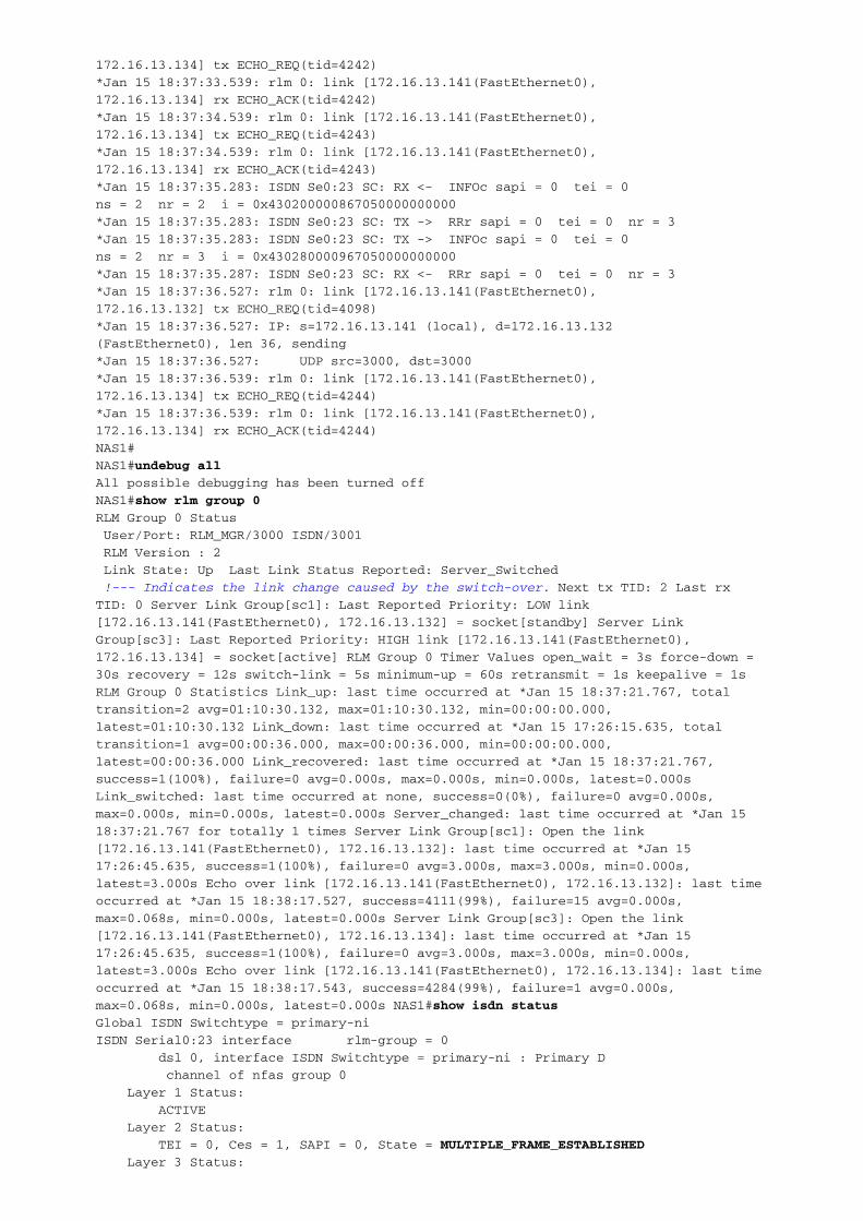
172.16.13.134] tx ECHO_REQ(tid=4242)
*Jan 15 18:37:33.539: rlm 0: link [172.16.13.141(FastEthernet0),
172.16.13.134] rx ECHO_ACK(tid=4242)
*Jan 15 18:37:34.539: rlm 0: link [172.16.13.141(FastEthernet0),
172.16.13.134] tx ECHO_REQ(tid=4243)
*Jan 15 18:37:34.539: rlm 0: link [172.16.13.141(FastEthernet0),
172.16.13.134] rx ECHO_ACK(tid=4243)
*Jan 15 18:37:35.283: ISDN Se0:23 SC: RX <- INFOc sapi = 0 tei = 0
ns = 2 nr = 2 i = 0x430200000867050000000000
*Jan 15 18:37:35.283: ISDN Se0:23 SC: TX -> RRr sapi = 0 tei = 0 nr = 3
*Jan 15 18:37:35.283: ISDN Se0:23 SC: TX -> INFOc sapi = 0 tei = 0
ns = 2 nr = 3 i = 0x430280000967050000000000
*Jan 15 18:37:35.287: ISDN Se0:23 SC: RX <- RRr sapi = 0 tei = 0 nr = 3
*Jan 15 18:37:36.527: rlm 0: link [172.16.13.141(FastEthernet0),
172.16.13.132] tx ECHO_REQ(tid=4098)
*Jan 15 18:37:36.527: IP: s=172.16.13.141 (local), d=172.16.13.132
(FastEthernet0), len 36, sending
*Jan 15 18:37:36.527: UDP src=3000, dst=3000
*Jan 15 18:37:36.539: rlm 0: link [172.16.13.141(FastEthernet0),
172.16.13.134] tx ECHO_REQ(tid=4244)
*Jan 15 18:37:36.539: rlm 0: link [172.16.13.141(FastEthernet0),
172.16.13.134] rx ECHO_ACK(tid=4244)
NAS1#
NAS1#undebug all
All possible debugging has been turned off
NAS1#show rlm group 0
RLM Group 0 Status
User/Port: RLM_MGR/3000 ISDN/3001
RLM Version : 2
Link State: Up Last Link Status Reported: Server_Switched
!--- Indicates the link change caused by the switch-over. Next tx TID: 2 Last rx
TID: 0 Server Link Group[sc1]: Last Reported Priority: LOW link
[172.16.13.141(FastEthernet0), 172.16.13.132] = socket[standby] Server Link
Group[sc3]: Last Reported Priority: HIGH link [172.16.13.141(FastEthernet0),
172.16.13.134] = socket[active] RLM Group 0 Timer Values open_wait = 3s force-down =
30s recovery = 12s switch-link = 5s minimum-up = 60s retransmit = 1s keepalive = 1s
RLM Group 0 Statistics Link_up: last time occurred at *Jan 15 18:37:21.767, total
transition=2 avg=01:10:30.132, max=01:10:30.132, min=00:00:00.000,
latest=01:10:30.132 Link_down: last time occurred at *Jan 15 17:26:15.635, total
transition=1 avg=00:00:36.000, max=00:00:36.000, min=00:00:00.000,
latest=00:00:36.000 Link_recovered: last time occurred at *Jan 15 18:37:21.767,
success=1(100%), failure=0 avg=0.000s, max=0.000s, min=0.000s, latest=0.000s
Link_switched: last time occurred at none, success=0(0%), failure=0 avg=0.000s,
max=0.000s, min=0.000s, latest=0.000s Server_changed: last time occurred at *Jan 15
18:37:21.767 for totally 1 times Server Link Group[sc1]: Open the link
[172.16.13.141(FastEthernet0), 172.16.13.132]: last time occurred at *Jan 15
17:26:45.635, success=1(100%), failure=0 avg=3.000s, max=3.000s, min=0.000s,
latest=3.000s Echo over link [172.16.13.141(FastEthernet0), 172.16.13.132]: last time
occurred at *Jan 15 18:38:17.527, success=4111(99%), failure=15 avg=0.000s,
max=0.068s, min=0.000s, latest=0.000s Server Link Group[sc3]: Open the link
[172.16.13.141(FastEthernet0), 172.16.13.134]: last time occurred at *Jan 15
17:26:45.635, success=1(100%), failure=0 avg=3.000s, max=3.000s, min=0.000s,
latest=3.000s Echo over link [172.16.13.141(FastEthernet0), 172.16.13.134]: last time
occurred at *Jan 15 18:38:17.543, success=4284(99%), failure=1 avg=0.000s,
max=0.068s, min=0.000s, latest=0.000s NAS1#show isdn status
Global ISDN Switchtype = primary-ni
ISDN Serial0:23 interface rlm-group = 0
dsl 0, interface ISDN Switchtype = primary-ni : Primary D
channel of nfas group 0
Layer 1 Status:
ACTIVE
Layer 2 Status:
TEI = 0, Ces = 1, SAPI = 0, State = MULTIPLE_FRAME_ESTABLISHED
Layer 3 Status:

0 Active Layer 3 Call(s)
Active dsl 0 CCBs = 0
The Free Channel Mask: 0x80FFFFFF
Total Allocated ISDN CCBs = 0
NAS1#
Determine the nature of a problem and then isolate the problem to a particular device orcomponent to troubleshoot. Use these tools to isolate the problem:
MML commands to retrieve the alarms reported, configuration, and perform call trace.●
Review the syslog file (/opt/CiscoMGC/var/log/platform.log) for clues to the problem.●
Turn on debug mode on the PGW 2200 for certain processes (such as engine or ISDN PRIover IP [PRIIP]).
●
Use the Snooper Tool to sniffer the IP packet between the PGW 2200 and the NAS gateway.●
Use the MML command rtrv-alms to view any alarms the system experiences. A more helpfulcommand to use is the rtrv-alms::cont to continuously listen for any current alarms that arereported. The most useful information is the platform.log file under the /opt/CiscoMGC/var/log/directory. This file contains all the information from the system. Since this file might be very large,use the UNIX command grep to search and parse through the file.
The key word to search for troubleshooting ISDN and RLM is IOCC-PRIIP, which is the I/OChannel Controller for PRIIP. Another method is to use tail –f platform.log under the/opt/CIscoMGC/var/log/ directory to continuously monitor in real-time any error message thatappears. You can set the PGW 2200 in debugging mode. Set the PRIIP process into debuggingmode and look deeper into the packet flows within the PGW 2200.
The other tool you can use is the Cisco Snooper. It can monitor (in real-time) different types ofprotocols (for example, RLM, SS7, ISDN, and H.225) that run over IP. It is like a sniffer connectedoff the Ethernet segment to monitor all types of traffic. This paper does not cover thetroubleshooting procedure using the Cisco Snooper tool.
This is some example output from the PGW 2200. In normal operation, there is constantcommunication between the NAS gateway and the PGW 2200. The keepalive messages can bemonitored on the PGW 2200. Enable the PGW 2200 to have the PRIIP process in debuggingmode with the MML command set-log:prrip-01:debug,confirm.
sc1 mml>rtrv-ne
MGC-01 - Media Gateway Controller 2002-01-15 21:48:14
M RTRV
"Type:MGC"
"Hardware platform:sun4u sparc SUNW,Ultra-60"
"Vendor:"Cisco Systems, Inc.""
"Location:MGC-01 - Media Gateway Controller"
"Version:"7.4(11)""
"Platform State:ACTIVE"
;
sc1 mml>help:set-log
MGC-01 - Media Gateway Controller 2002-01-15 21:48:26
M RTRV
SET-LOG -- Set Logging Levels
-----------------------------
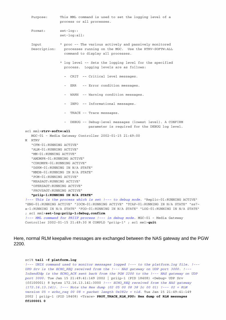
Purpose: This MML command is used to set the logging level of a
process or all processes.
Format: set-log::
set-log:all:
Input * proc -- The various actively and passively monitored
Description: processes running on the MGC. Use the RTRV-SOFTW:ALL
command to display all processes.
* log level -- Sets the logging level for the specified
process. Logging levels are as follows:
- CRIT -- Critical level messages.
- ERR -- Error condition messages.
- WARN -- Warning condition messages.
- INFO -- Informational messages.
- TRACE -- Trace messages.
- DEBUG -- Debug-level messages (lowest level). A CONFIRM
parameter is required for the DEBUG log level.
sc1 mml>rtrv-softw:all
MGC-01 - Media Gateway Controller 2002-01-15 21:49:00
M RTRV
"CFM-01:RUNNING ACTIVE"
"ALM-01:RUNNING ACTIVE"
"MM-01:RUNNING ACTIVE"
"AMDMPR-01:RUNNING ACTIVE"
"CDRDMPR-01:RUNNING ACTIVE"
"DSKM-01:RUNNING IN N/A STATE"
"MMDB-01:RUNNING IN N/A STATE"
"POM-01:RUNNING ACTIVE"
"MEASAGT:RUNNING ACTIVE"
"OPERSAGT:RUNNING ACTIVE"
"PROVSAGT:RUNNING ACTIVE"
"priip-1:RUNNING IN N/A STATE"
!--- This is the process which is set !--- to debug mode. "Replic-01:RUNNING ACTIVE"
"ENG-01:RUNNING ACTIVE" "IOCM-01:RUNNING ACTIVE" "TCAP-01:RUNNING IN N/A STATE" "ss7-
a-1:RUNNING IN N/A STATE" "FOD-01:RUNNING IN N/A STATE" "LOG-01:RUNNING IN N/A STATE"
; sc1 mml>set-log:priip-1:debug,confirm
!--- MML command for PRIIP process !--- in debug mode. MGC-01 - Media Gateway
Controller 2002-01-15 21:49:30 M COMPLD "priip-1" ; sc1 mml>quit
Here, normal RLM keepalive messages are exchanged between the NAS gateway and the PGW2200.
sc1% tail -f platform.log
!--- UNIX command used to monitor messages logged !--- to the platform.log file. !---
UPD Srv is the ECHO_REQ received from the !--- NAS gateway on UDP port 3000. !---
IoSendUdp is the ECHO_ACK sent back from the PGW 2200 to the !--- NAS gateway on UDP
port 3000. Tue Jan 15 21:49:41:149 2002 | priip-1 (PID 18408) <Debug> UDP Srv
(ff100001) 8 bytes 172.16.13.141:3000 !--- ECHO_REQ received from the NAS gateway
(172.16.13.141). !--- Note the Hex dump (02 05 00 08 38 2c 00 01) !--- 02 = RLM
version 05 = echo_req 00 08 = packet length 0x382c = tid. Tue Jan 15 21:49:41:149
2002 | priip-1 (PID 18408) <Trace> PROT_TRACE_RLM_PDU: Hex dump of RLM messages
ff100001 0

(8) 02 05 00 08 38 2c 00 01
Tue Jan 15 21:49:41:149 2002 | priip-1 (PID 18408) <Debug>
ioSendUdp: Server fd 8 Dsl 0 IP 172.16.13.141:3000
!--- ECHO_ACK sent back from PGW 2200 to the NAS gateway. !--- Note the Hex dump (02
06 00 08 38 2c 00 02) !--- 0x02 = RLM version 0x06 = echo_ack 0x0008 = packet length
0x382c = tid. Tue Jan 15 21:49:41:149 2002 | priip-1 (PID 18408) PROT_TRACE_RLM_PDU:
Hex dump of RLM messages ff100001 1 (8)
02 06 00 08 38 2c 00 02
This output is the normal ISDN keepalive message between the NAS gateway and the PGW 2200.
!--- UPD Srv is the ISDN RRp keepalive !--- received from the NAS gateway on UDP port
3001. !--- IoSendUdp is the ISDN RRf keepalive sent back from the PGW 2200 !--- to
the NAS gateway on UDP port 3001. Tue Jan 15 23:05:32:890 2002 | priip-1 (PID 18408)
<Debug> UDP Srv (00100001) 4 bytes 172.16.13.141:3001
Tue Jan 15 23:05:32:890 2002 | priip-1 (PID 18408) <Trace>
PROT_TRACE_Q921_PDU: Hex dump of Q921 messages 100001 0 (4) 00 01 01 0b
Tue Jan 15 23:05:32:890 2002 | priip-1 (PID 18408) <Debug>
[ LINK 1 24 0 STATE 3 EVENT RR ]
Tue Jan 15 23:05:32:890 2002 | priip-1 (PID 18408) <Debug>
ioSendUdp: Server fd 9 Dsl 1 IP 172.16.13.141:3001
Tue Jan 15 23:05:32:890 2002 | priip-1 (PID 18408) <Trace>
PROT_TRACE_Q921_PDU: Hex dump of Q921 messages 100001 1 (4) 00 01 01 0b
This is an example of abnormal ISDN signaling. The keepalive is not received by the PGW 2200from the NAS gateway.
!--- UPD Srv is the ISDN RRp keepalive !--- received from the NAS gateway on UDP port
3001. !--- IoSendUdp is the ISDN RRf keepalive sent back from the PGW 2200 !--- to
the NAS gateway on UDP port 3001. Tue Jan 15 23:05:32:890 2002 | priip-1 (PID 18408)
<Debug> UDP Srv (00100001) 4 bytes 172.16.13.141:3001
Tue Jan 15 23:05:32:890 2002 | priip-1 (PID 18408) <Trace>
PROT_TRACE_Q921_PDU: Hex dump of Q921 messages 100001 0 (4) 00 01 01 0b
Tue Jan 15 23:05:32:890 2002 | priip-1 (PID 18408) <Debug>
[ LINK 1 24 0 STATE 3 EVENT RR ]
Tue Jan 15 23:05:32:890 2002 | priip-1 (PID 18408) <Debug>
ioSendUdp: Server fd 9 Dsl 1 IP 172.16.13.141:3001
Tue Jan 15 23:05:32:890 2002 | priip-1 (PID 18408) <Trace>
PROT_TRACE_Q921_PDU: Hex dump of Q921 messages 100001 1 (4) 00 01 01 0b
This section is the debug capture for the PGW 2200 when the D-channel is brought back in-service (no shutdown).
Note: The comments are numbered as a reference to the corresponding debug on the NASgateway.
PGW 2200 Debug
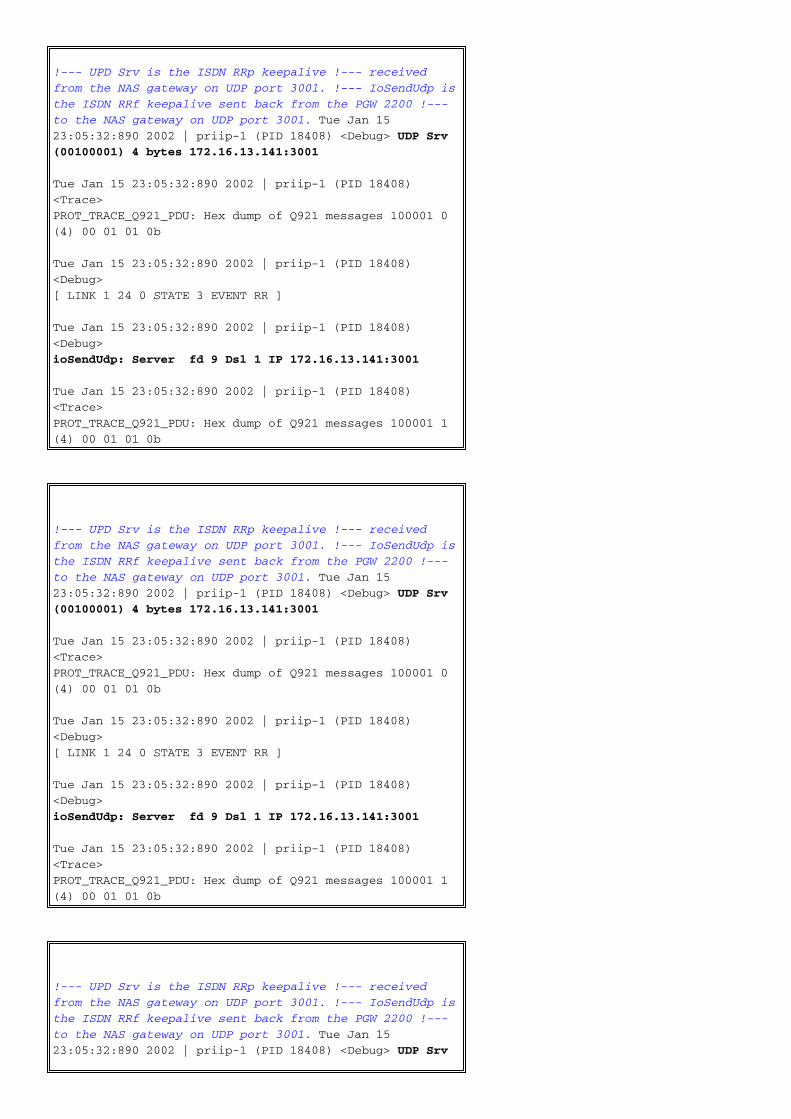
!--- UPD Srv is the ISDN RRp keepalive !--- received
from the NAS gateway on UDP port 3001. !--- IoSendUdp is
the ISDN RRf keepalive sent back from the PGW 2200 !---
to the NAS gateway on UDP port 3001. Tue Jan 15
23:05:32:890 2002 | priip-1 (PID 18408) <Debug> UDP Srv
(00100001) 4 bytes 172.16.13.141:3001
Tue Jan 15 23:05:32:890 2002 | priip-1 (PID 18408)
<Trace>
PROT_TRACE_Q921_PDU: Hex dump of Q921 messages 100001 0
(4) 00 01 01 0b
Tue Jan 15 23:05:32:890 2002 | priip-1 (PID 18408)
<Debug>
[ LINK 1 24 0 STATE 3 EVENT RR ]
Tue Jan 15 23:05:32:890 2002 | priip-1 (PID 18408)
<Debug>
ioSendUdp: Server fd 9 Dsl 1 IP 172.16.13.141:3001
Tue Jan 15 23:05:32:890 2002 | priip-1 (PID 18408)
<Trace>
PROT_TRACE_Q921_PDU: Hex dump of Q921 messages 100001 1
(4) 00 01 01 0b
!--- UPD Srv is the ISDN RRp keepalive !--- received
from the NAS gateway on UDP port 3001. !--- IoSendUdp is
the ISDN RRf keepalive sent back from the PGW 2200 !---
to the NAS gateway on UDP port 3001. Tue Jan 15
23:05:32:890 2002 | priip-1 (PID 18408) <Debug> UDP Srv
(00100001) 4 bytes 172.16.13.141:3001
Tue Jan 15 23:05:32:890 2002 | priip-1 (PID 18408)
<Trace>
PROT_TRACE_Q921_PDU: Hex dump of Q921 messages 100001 0
(4) 00 01 01 0b
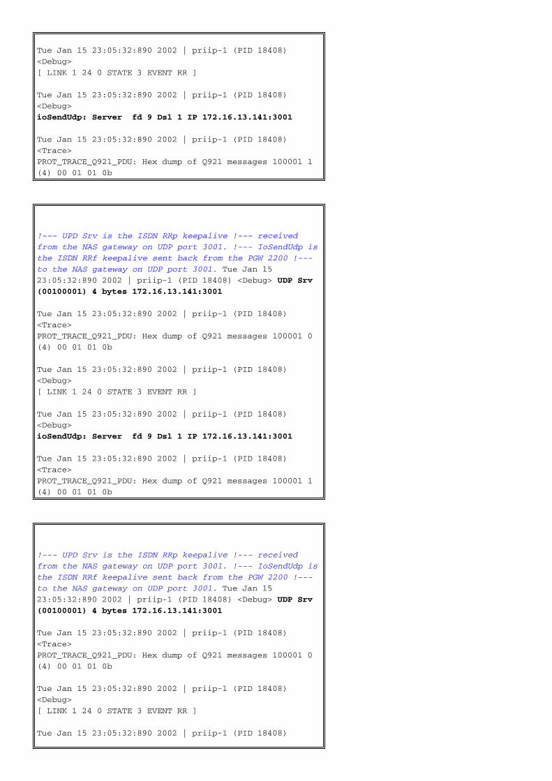
Tue Jan 15 23:05:32:890 2002 | priip-1 (PID 18408)
<Debug>
[ LINK 1 24 0 STATE 3 EVENT RR ]
Tue Jan 15 23:05:32:890 2002 | priip-1 (PID 18408)
<Debug>
ioSendUdp: Server fd 9 Dsl 1 IP 172.16.13.141:3001
Tue Jan 15 23:05:32:890 2002 | priip-1 (PID 18408)
<Trace>
PROT_TRACE_Q921_PDU: Hex dump of Q921 messages 100001 1
(4) 00 01 01 0b
!--- UPD Srv is the ISDN RRp keepalive !--- received
from the NAS gateway on UDP port 3001. !--- IoSendUdp is
the ISDN RRf keepalive sent back from the PGW 2200 !---
to the NAS gateway on UDP port 3001. Tue Jan 15
23:05:32:890 2002 | priip-1 (PID 18408) <Debug> UDP Srv
(00100001) 4 bytes 172.16.13.141:3001
Tue Jan 15 23:05:32:890 2002 | priip-1 (PID 18408)
<Trace>
PROT_TRACE_Q921_PDU: Hex dump of Q921 messages 100001 0
(4) 00 01 01 0b
Tue Jan 15 23:05:32:890 2002 | priip-1 (PID 18408)
<Debug>
[ LINK 1 24 0 STATE 3 EVENT RR ]
Tue Jan 15 23:05:32:890 2002 | priip-1 (PID 18408)
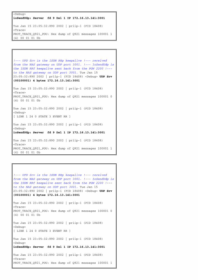
<Debug>
ioSendUdp: Server fd 9 Dsl 1 IP 172.16.13.141:3001
Tue Jan 15 23:05:32:890 2002 | priip-1 (PID 18408)
<Trace>
PROT_TRACE_Q921_PDU: Hex dump of Q921 messages 100001 1
(4) 00 01 01 0b
!--- UPD Srv is the ISDN RRp keepalive !--- received
from the NAS gateway on UDP port 3001. !--- IoSendUdp is
the ISDN RRf keepalive sent back from the PGW 2200 !---
to the NAS gateway on UDP port 3001. Tue Jan 15
23:05:32:890 2002 | priip-1 (PID 18408) <Debug> UDP Srv
(00100001) 4 bytes 172.16.13.141:3001
Tue Jan 15 23:05:32:890 2002 | priip-1 (PID 18408)
<Trace>
PROT_TRACE_Q921_PDU: Hex dump of Q921 messages 100001 0
(4) 00 01 01 0b
Tue Jan 15 23:05:32:890 2002 | priip-1 (PID 18408)
<Debug>
[ LINK 1 24 0 STATE 3 EVENT RR ]
Tue Jan 15 23:05:32:890 2002 | priip-1 (PID 18408)
<Debug>
ioSendUdp: Server fd 9 Dsl 1 IP 172.16.13.141:3001
Tue Jan 15 23:05:32:890 2002 | priip-1 (PID 18408)
<Trace>
PROT_TRACE_Q921_PDU: Hex dump of Q921 messages 100001 1

(4) 00 01 01 0b
!--- UPD Srv is the ISDN RRp keepalive !--- received
from the NAS gateway on UDP port 3001. !--- IoSendUdp is
the ISDN RRf keepalive sent back from the PGW 2200 !---
to the NAS gateway on UDP port 3001. Tue Jan 15
23:05:32:890 2002 | priip-1 (PID 18408) <Debug> UDP Srv
(00100001) 4 bytes 172.16.13.141:3001
Tue Jan 15 23:05:32:890 2002 | priip-1 (PID 18408)
<Trace>
PROT_TRACE_Q921_PDU: Hex dump of Q921 messages 100001 0
(4) 00 01 01 0b
Tue Jan 15 23:05:32:890 2002 | priip-1 (PID 18408)
<Debug>
[ LINK 1 24 0 STATE 3 EVENT RR ]
Tue Jan 15 23:05:32:890 2002 | priip-1 (PID 18408)
<Debug>
ioSendUdp: Server fd 9 Dsl 1 IP 172.16.13.141:3001
Tue Jan 15 23:05:32:890 2002 | priip-1 (PID 18408)
<Trace>
PROT_TRACE_Q921_PDU: Hex dump of Q921 messages 100001 1
(4) 00 01 01 0b
!--- UPD Srv is the ISDN RRp keepalive !--- received
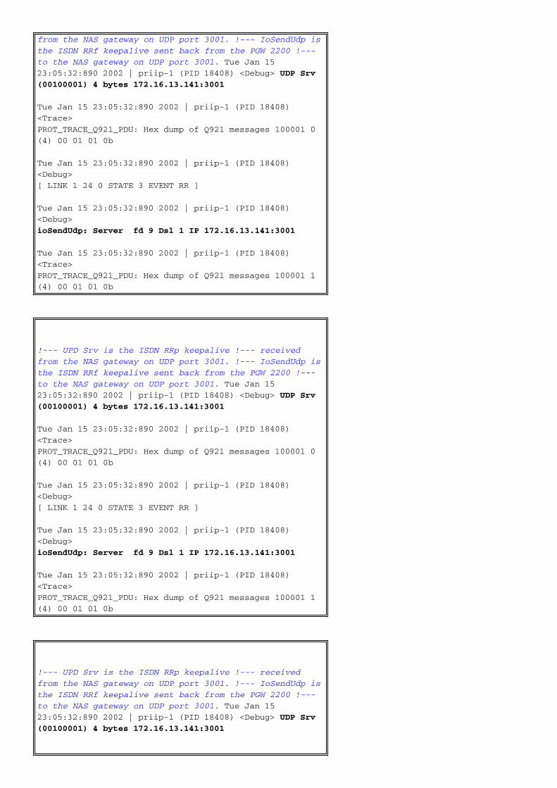
from the NAS gateway on UDP port 3001. !--- IoSendUdp is
the ISDN RRf keepalive sent back from the PGW 2200 !---
to the NAS gateway on UDP port 3001. Tue Jan 15
23:05:32:890 2002 | priip-1 (PID 18408) <Debug> UDP Srv
(00100001) 4 bytes 172.16.13.141:3001
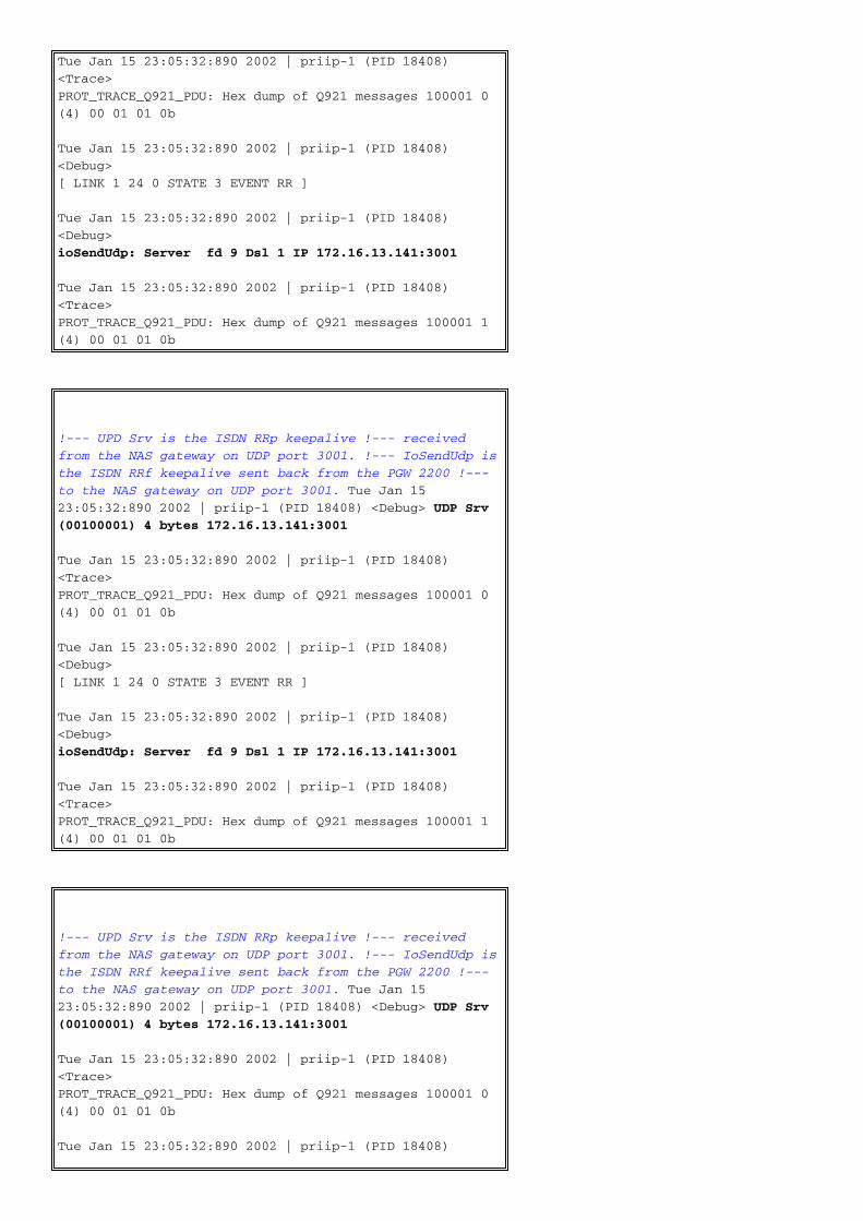
Tue Jan 15 23:05:32:890 2002 | priip-1 (PID 18408)
<Trace>
PROT_TRACE_Q921_PDU: Hex dump of Q921 messages 100001 0
(4) 00 01 01 0b
Tue Jan 15 23:05:32:890 2002 | priip-1 (PID 18408)
<Debug>
[ LINK 1 24 0 STATE 3 EVENT RR ]
Tue Jan 15 23:05:32:890 2002 | priip-1 (PID 18408)
<Debug>
ioSendUdp: Server fd 9 Dsl 1 IP 172.16.13.141:3001
Tue Jan 15 23:05:32:890 2002 | priip-1 (PID 18408)
<Trace>
PROT_TRACE_Q921_PDU: Hex dump of Q921 messages 100001 1
(4) 00 01 01 0b
!--- UPD Srv is the ISDN RRp keepalive !--- received
from the NAS gateway on UDP port 3001. !--- IoSendUdp is
the ISDN RRf keepalive sent back from the PGW 2200 !---
to the NAS gateway on UDP port 3001. Tue Jan 15
23:05:32:890 2002 | priip-1 (PID 18408) <Debug> UDP Srv
(00100001) 4 bytes 172.16.13.141:3001
Tue Jan 15 23:05:32:890 2002 | priip-1 (PID 18408)
<Trace>
PROT_TRACE_Q921_PDU: Hex dump of Q921 messages 100001 0
(4) 00 01 01 0b
Tue Jan 15 23:05:32:890 2002 | priip-1 (PID 18408)

<Debug>
[ LINK 1 24 0 STATE 3 EVENT RR ]
Tue Jan 15 23:05:32:890 2002 | priip-1 (PID 18408)
<Debug>
ioSendUdp: Server fd 9 Dsl 1 IP 172.16.13.141:3001
Tue Jan 15 23:05:32:890 2002 | priip-1 (PID 18408)
<Trace>
PROT_TRACE_Q921_PDU: Hex dump of Q921 messages 100001 1
(4) 00 01 01 0b
!--- UPD Srv is the ISDN RRp keepalive !--- received
from the NAS gateway on UDP port 3001. !--- IoSendUdp is
the ISDN RRf keepalive sent back from the PGW 2200 !---
to the NAS gateway on UDP port 3001. Tue Jan 15
23:05:32:890 2002 | priip-1 (PID 18408) <Debug> UDP Srv
(00100001) 4 bytes 172.16.13.141:3001
Tue Jan 15 23:05:32:890 2002 | priip-1 (PID 18408)
<Trace>
PROT_TRACE_Q921_PDU: Hex dump of Q921 messages 100001 0
(4) 00 01 01 0b
Tue Jan 15 23:05:32:890 2002 | priip-1 (PID 18408)
<Debug>
[ LINK 1 24 0 STATE 3 EVENT RR ]
Tue Jan 15 23:05:32:890 2002 | priip-1 (PID 18408)
<Debug>
ioSendUdp: Server fd 9 Dsl 1 IP 172.16.13.141:3001
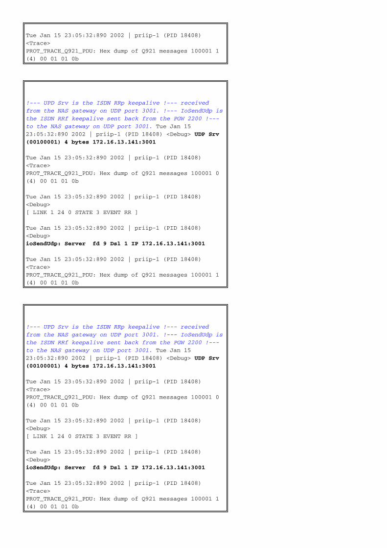
Tue Jan 15 23:05:32:890 2002 | priip-1 (PID 18408)
<Trace>
PROT_TRACE_Q921_PDU: Hex dump of Q921 messages 100001 1
(4) 00 01 01 0b
!--- UPD Srv is the ISDN RRp keepalive !--- received
from the NAS gateway on UDP port 3001. !--- IoSendUdp is
the ISDN RRf keepalive sent back from the PGW 2200 !---
to the NAS gateway on UDP port 3001. Tue Jan 15
23:05:32:890 2002 | priip-1 (PID 18408) <Debug> UDP Srv
(00100001) 4 bytes 172.16.13.141:3001
Tue Jan 15 23:05:32:890 2002 | priip-1 (PID 18408)
<Trace>
PROT_TRACE_Q921_PDU: Hex dump of Q921 messages 100001 0
(4) 00 01 01 0b
Tue Jan 15 23:05:32:890 2002 | priip-1 (PID 18408)
<Debug>
[ LINK 1 24 0 STATE 3 EVENT RR ]
Tue Jan 15 23:05:32:890 2002 | priip-1 (PID 18408)
<Debug>
ioSendUdp: Server fd 9 Dsl 1 IP 172.16.13.141:3001
Tue Jan 15 23:05:32:890 2002 | priip-1 (PID 18408)
<Trace>
PROT_TRACE_Q921_PDU: Hex dump of Q921 messages 100001 1
(4) 00 01 01 0b
This command output is a duplicate of the previous command output from the NAS side. Noticethe corresponding numbered comments.
NAS
NAS1#show debug
ISDN:
ISDN Q921 packets debugging is on
ISDN Q931 packets debugging is on
ISDN Q921 packets debug DSLs. (On/Off/No DSL:1/0/-)
DSL 0 --> 7
1 - - - - - - -
ISDN Q931 packets debug DSLs. (On/Off/No DSL:1/0/-)
DSL 0 --> 7
1 - - - - - - -
NAS1#configure terminal
Enter configuration commands, one per line. End with
CNTL/Z.
NAS1(config)#interface s0:23
NAS1(config-if)#no shut
NAS1(config-if)#
Jan 16 17:02:45.310: %CSM-5-PRI: add PRI at slot 0, unit
0, channel 23 with index 0
Jan 16 17:02:47.310: %LINK-3-UPDOWN: Interface
Serial0:23, changed state to up
Jan 16 17:02:47.310: ISDN Se0:23 SC: TX -> SABMEp c/r =
0 sapi = 0 tei = 0
!--- 1. The NAS tries to re-establish the ISDN link.
Jan 16 17:02:47.314: ISDN Se0:23 SC: RX <- UAf c/r = 0
sapi = 0 tei = 0
NAS1#show debug
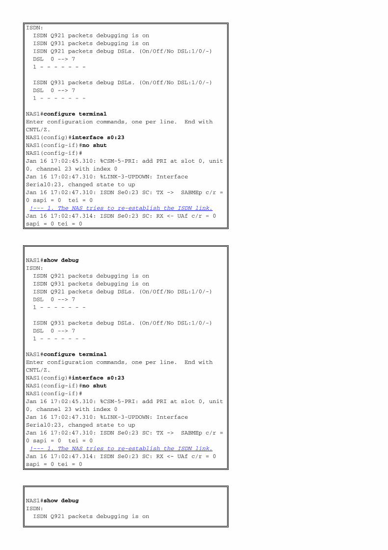
ISDN:
ISDN Q921 packets debugging is on
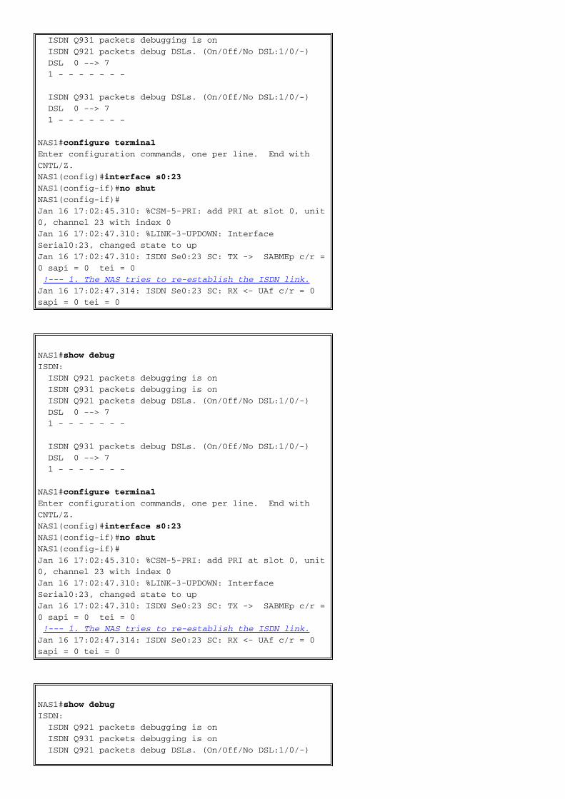
ISDN Q931 packets debugging is on
ISDN Q921 packets debug DSLs. (On/Off/No DSL:1/0/-)
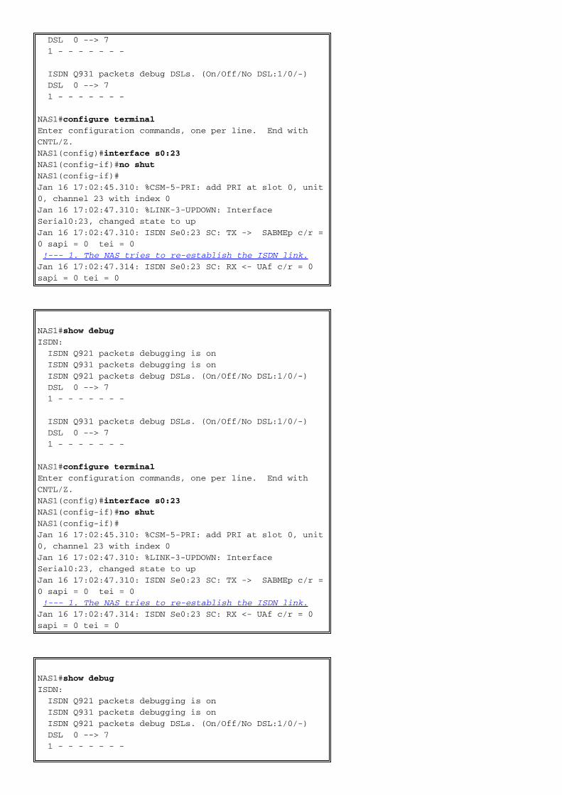
DSL 0 --> 7
1 - - - - - - -
ISDN Q931 packets debug DSLs. (On/Off/No DSL:1/0/-)
DSL 0 --> 7
1 - - - - - - -
NAS1#configure terminal
Enter configuration commands, one per line. End with
CNTL/Z.
NAS1(config)#interface s0:23
NAS1(config-if)#no shut
NAS1(config-if)#
Jan 16 17:02:45.310: %CSM-5-PRI: add PRI at slot 0, unit
0, channel 23 with index 0
Jan 16 17:02:47.310: %LINK-3-UPDOWN: Interface
Serial0:23, changed state to up
Jan 16 17:02:47.310: ISDN Se0:23 SC: TX -> SABMEp c/r =
0 sapi = 0 tei = 0
!--- 1. The NAS tries to re-establish the ISDN link.
Jan 16 17:02:47.314: ISDN Se0:23 SC: RX <- UAf c/r = 0
sapi = 0 tei = 0
NAS1#show debug
ISDN:
ISDN Q921 packets debugging is on
ISDN Q931 packets debugging is on
ISDN Q921 packets debug DSLs. (On/Off/No DSL:1/0/-)
DSL 0 --> 7
1 - - - - - - -
ISDN Q931 packets debug DSLs. (On/Off/No DSL:1/0/-)

DSL 0 --> 7
1 - - - - - - -
NAS1#configure terminal
Enter configuration commands, one per line. End with
CNTL/Z.
NAS1(config)#interface s0:23
NAS1(config-if)#no shut
NAS1(config-if)#
Jan 16 17:02:45.310: %CSM-5-PRI: add PRI at slot 0, unit
0, channel 23 with index 0
Jan 16 17:02:47.310: %LINK-3-UPDOWN: Interface
Serial0:23, changed state to up
Jan 16 17:02:47.310: ISDN Se0:23 SC: TX -> SABMEp c/r =
0 sapi = 0 tei = 0
!--- 1. The NAS tries to re-establish the ISDN link.
Jan 16 17:02:47.314: ISDN Se0:23 SC: RX <- UAf c/r = 0
sapi = 0 tei = 0
NAS1#show debug
ISDN:
ISDN Q921 packets debugging is on
ISDN Q931 packets debugging is on
ISDN Q921 packets debug DSLs. (On/Off/No DSL:1/0/-)
DSL 0 --> 7
1 - - - - - - -
ISDN Q931 packets debug DSLs. (On/Off/No DSL:1/0/-)
DSL 0 --> 7
1 - - - - - - -
NAS1#configure terminal
Enter configuration commands, one per line. End with
CNTL/Z.
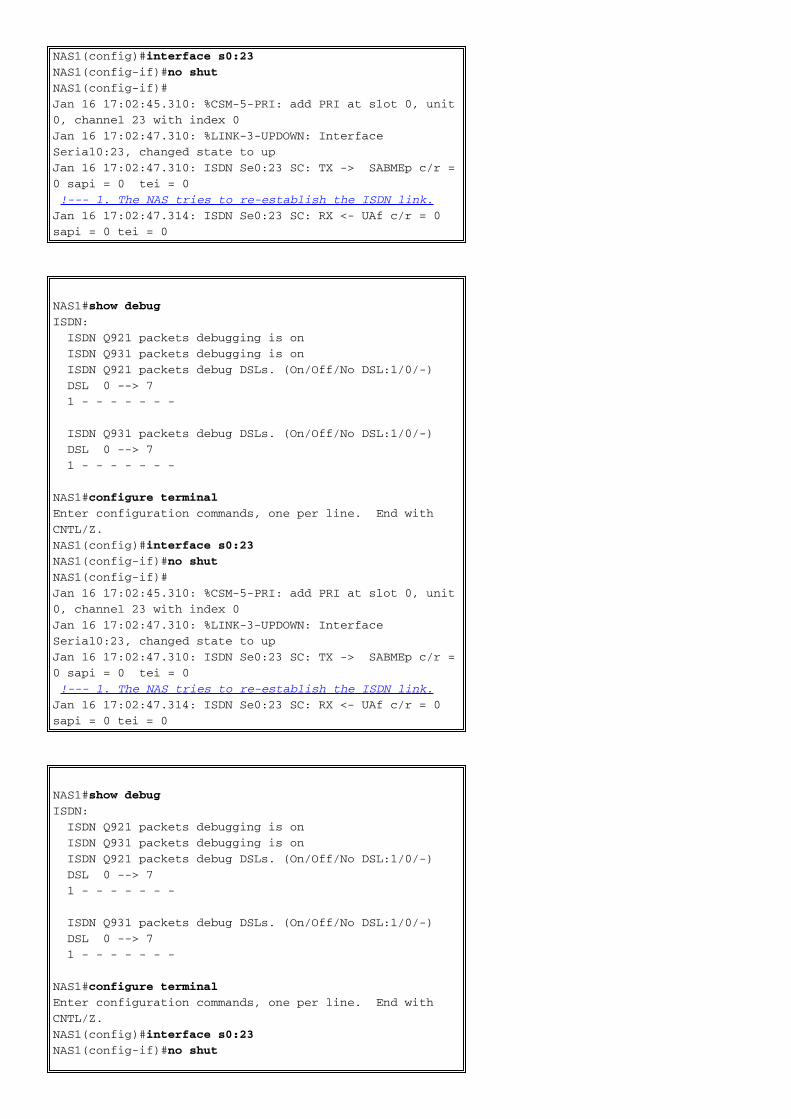
NAS1(config)#interface s0:23
NAS1(config-if)#no shut
NAS1(config-if)#
Jan 16 17:02:45.310: %CSM-5-PRI: add PRI at slot 0, unit
0, channel 23 with index 0
Jan 16 17:02:47.310: %LINK-3-UPDOWN: Interface
Serial0:23, changed state to up
Jan 16 17:02:47.310: ISDN Se0:23 SC: TX -> SABMEp c/r =
0 sapi = 0 tei = 0
!--- 1. The NAS tries to re-establish the ISDN link.
Jan 16 17:02:47.314: ISDN Se0:23 SC: RX <- UAf c/r = 0
sapi = 0 tei = 0
RESYNC_REQ/RESYNC_RESP
The RESYNC_REQ/RESYNC_RESP messages are used to checkpoint the call states betweenthe PGW 2200 and the NASes. These messages are typically generated after a switch-over eventto determine if any discrepancies occurred in the call states. These messages are used to re-establish a consistent view of the channel call states on both the PGW 2200 and NAS gateway toprevent any possible hang CIC.
Group Service Message
Similar to the RESYNC message, the Group Service messages use a single message per D-channel to indicate the service state (IS/OOS) of all of the associated B-channels. The NASinitiates the Group Service operation. Actions are taken on the PGW 2200 side to maintainconsistency of the channel states based on the result of comparing the state of each channel.When the PGW 2200 receives this message, it sends out SS7 ISUP circuit group block(CGB/CGBA) and circuit group unblock (CGU/CGUA) to correspond to the B-channel serviceindications from the group service messages. In addition, the acknowledgement to the groupservice message from the NAS does not occur until the signaling gateway receives a CGBA or
CGUA from the PSTN switch.
In the Cisco SS7 Interconnection voice gateway solutions configuration, bearer channels from aNAS are mated (nailed up) to SS7 bearers. Before, the PGW 2200 engine handled each individualNAS service messages by setting bearer channel service states. When many channels on a NASchange state simultaneously, the resulting service messages can flood the switch if they are sentindividually. A group service message sent from the NAS efficiently informs the engine of the stateof all bearer channels. The engine must decode this message, change the state of each NI-2bearer channel, and propagate the changes to the SS7 side, from which corresponding block andunblock channel management messages (CGB/CGBA and CGU/CGUA) must be sent. This allowsfor maximum efficiency. This Group Service Message (GSM) helps minimize the number ofSERVICE/SERVICE ACK message transactions in the event of more than one channel (orinterface) being taken into out-of-service or in-service. Group Service messages can handle up tothirty interfaces at a time.
If you encounter any problems, collect an SS7/NI2+ RLM sniffer trace:
Collect snoop/NI2+ / RLM / -SS7 Sniffer Traces●
This section lists several methods for collecting sniffer traces. Which one you choose depends onwhether you have Cisco Packet Telephony Center—Monitoring and Troubleshooting (PTC-MT)installed or are running an old version of Cisco snooper. Cisco snooper can give a goodunderstanding of the SS7-SIP call flow.
You can issue the snoop command on all Solaris platforms. Log in as superuser and issuethis command to collect UNIX snoop information:
snoop -o snoop.log IP address
Ctrl C - to exit snoop
Upload the snoop.log file to the case notes.Note: Explain in the case notes that this file wascaptured through use of the UNIX snoop command.
●
Run the Cisco snooper application. Log in as a superuser and issue the ./snooper intINTERFACE PARMS LIST command or run ./snooper to collect Cisco snooper information,which gives you a full description.
./snooper int hme'x' ni2+ rlm ss7 > snooper_int1
!--- Where 'x' is the interface number, which you can also find !--- by issuing the ifconfig
-a command.
Upload the snooper_int1 file to the case notes.
●
Run PTC-MT.In order to collect PTC-MT information, log in as a superuser and issue the./ptcmt int INTERFACE PARMS LIST command or run ./snooper, which gives you a fulldescription.
./ptcmt int hme'x' ni2+ rlm ss7 > snooper_int1
!--- Where 'x' is the interface number, which you can also find !--- by issuing the ifconfig
-a command.
Upload the snooper_int1 file to the case notes.
●
On the Cisco IOS NAS, issue the IOS commands show isdn status, show rlm group 'x',and debug isdn q931.
●
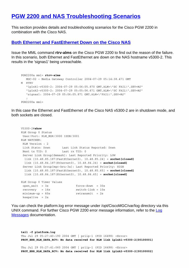
PGW 2200 and NAS Troubleshooting Scenarios
This section provides details and troubleshooting scenarios for the Cisco PGW 2200 incombination with the Cisco NAS.
Both Ethernet and FastEthernet Down on the Cisco NAS
Issue the MML command rtrv-alms on the Cisco PGW 2200 to find out the reason of the failure.In this scenario, both Ethernet and FastEthernet are down on the NAS hostname v5300-2. Thisresults in the 'signas1' being unreachable.
PGW2200a mml> rtrv-alms
MGC-02 - Media Gateway Controller 2004-07-29 05:14:38.471 GMT
M RTRV
"iplnk1-v5300-2: 2004-07-29 05:06:05.870 GMT,ALM=\"SC FAIL\",SEV=MJ"
"iplnk2-v5300-2: 2004-07-29 05:05:06.671 GMT,ALM=\"SC FAIL\",SEV=MJ"
"signas1: 2004-07-29 05:06:05.871 GMT,ALM=\"FAIL\",SEV=MJ"
;
PGW2200a mml>
In this case the Ethernet and FastEthernet of the Cisco NAS v5300-2 are in shutdown mode, andboth sockets are closed.
V5300-2#show
RLM Group 0 Status
User/Port: RLM_MGR/3000 ISDN/3001
RLM WATCHER:
RLM Version : 2
Link State: Down Last Link Status Reported: Down
Next tx TID: 0 Last rx TID: 0
Server Link Group[demask]: Last Reported Priority: LOW
link [10.48.85.187(FastEthernet0), 10.48.85.24] = socket[closed]
link [10.48.84.187(Ethernet0), 10.48.84.24] = socket[closed]
Server Link Group[mgc-bru-3a]: Last Reported Priority: HIGH
link [10.48.85.187(FastEthernet0), 10.48.85.65] = socket[closed]
link [10.48.84.187(Ethernet0), 10.48.84.65] = socket[closed]
RLM Group 0 Timer Values
open_wait = 3s force-down = 30s
recovery = 16s switch-link = 10s
minimum-up = 60s retransmit = 2s
keepalive = 2s
You can check the platform.log error message under /opt/CiscoMGC/var/log directory via thisUNIX command. For further Cisco PGW 2200 error message information, refer to the LogMessages documentation.
tail -f platform.log
Thu Jul 29 05:27:40:190 2004 GMT | priip-1 (PID 16498) <Error>
PROT_ERR_RLM_DATA_RCV: No data received for RLM link iplnk1-v5300-2[00100001]
Thu Jul 29 05:27:41:060 2004 GMT | priip-1 (PID 16498) <Error>
PROT_ERR_RLM_DATA_RCV: No data received for RLM link iplnk2-v5300-2[00100002]
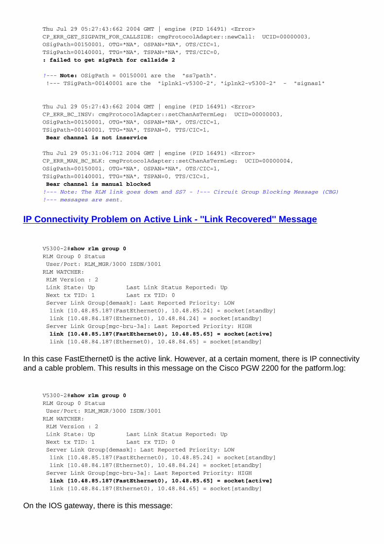
Thu Jul 29 05:27:43:662 2004 GMT | engine (PID 16491) <Error>
CP_ERR_GET_SIGPATH_FOR_CALLSIDE: cmgProtocolAdapter::newCall: UCID=00000003,
OSigPath=00150001, OTG=*NA*, OSPAN=*NA*, OTS/CIC=1,
TSigPath=00140001, TTG=*NA*, TSPAN=*NA*, TTS/CIC=0,
: failed to get sigPath for callside 2
!--- Note: OSigPath = 00150001 are the "ss7path".
!--- TSigPath=00140001 are the "iplnk1-v5300-2", "iplnk2-v5300-2" - "signas1"
Thu Jul 29 05:27:43:662 2004 GMT | engine (PID 16491) <Error>
CP_ERR_BC_INSV: cmgProtocolAdapter::setChanAsTermLeg: UCID=00000003,
OSigPath=00150001, OTG=*NA*, OSPAN=*NA*, OTS/CIC=1,
TSigPath=00140001, TTG=*NA*, TSPAN=0, TTS/CIC=1,
Bear channel is not inservice
Thu Jul 29 05:31:06:712 2004 GMT | engine (PID 16491) <Error>
CP_ERR_MAN_BC_BLK: cmgProtocolAdapter::setChanAsTermLeg: UCID=00000004,
OSigPath=00150001, OTG=*NA*, OSPAN=*NA*, OTS/CIC=1,
TSigPath=00140001, TTG=*NA*, TSPAN=0, TTS/CIC=1,
Bear channel is manual blocked
!--- Note: The RLM link goes down and SS7 - !--- Circuit Group Blocking Message (CBG)
!--- messages are sent.
IP Connectivity Problem on Active Link - ''Link Recovered'' Message
V5300-2#show rlm group 0
RLM Group 0 Status
User/Port: RLM_MGR/3000 ISDN/3001
RLM WATCHER:
RLM Version : 2
Link State: Up Last Link Status Reported: Up
Next tx TID: 1 Last rx TID: 0
Server Link Group[demask]: Last Reported Priority: LOW
link [10.48.85.187(FastEthernet0), 10.48.85.24] = socket[standby]
link [10.48.84.187(Ethernet0), 10.48.84.24] = socket[standby]
Server Link Group[mgc-bru-3a]: Last Reported Priority: HIGH
link [10.48.85.187(FastEthernet0), 10.48.85.65] = socket[active]
link [10.48.84.187(Ethernet0), 10.48.84.65] = socket[standby]
In this case FastEthernet0 is the active link. However, at a certain moment, there is IP connectivityand a cable problem. This results in this message on the Cisco PGW 2200 for the patform.log:
V5300-2#show rlm group 0
RLM Group 0 Status
User/Port: RLM_MGR/3000 ISDN/3001
RLM WATCHER:
RLM Version : 2
Link State: Up Last Link Status Reported: Up
Next tx TID: 1 Last rx TID: 0
Server Link Group[demask]: Last Reported Priority: LOW
link [10.48.85.187(FastEthernet0), 10.48.85.24] = socket[standby]
link [10.48.84.187(Ethernet0), 10.48.84.24] = socket[standby]
Server Link Group[mgc-bru-3a]: Last Reported Priority: HIGH
link [10.48.85.187(FastEthernet0), 10.48.85.65] = socket[active]
link [10.48.84.187(Ethernet0), 10.48.84.65] = socket[standby]
On the IOS gateway, there is this message:
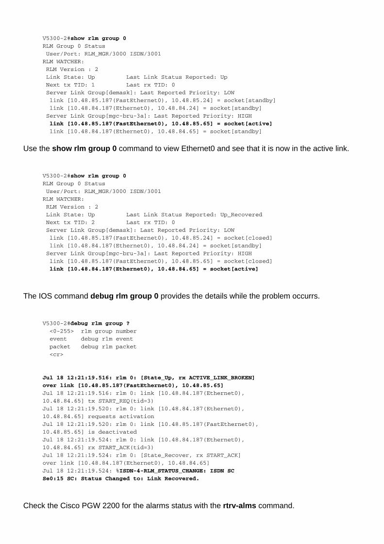
V5300-2#show rlm group 0
RLM Group 0 Status
User/Port: RLM_MGR/3000 ISDN/3001
RLM WATCHER:
RLM Version : 2
Link State: Up Last Link Status Reported: Up
Next tx TID: 1 Last rx TID: 0
Server Link Group[demask]: Last Reported Priority: LOW
link [10.48.85.187(FastEthernet0), 10.48.85.24] = socket[standby]
link [10.48.84.187(Ethernet0), 10.48.84.24] = socket[standby]
Server Link Group[mgc-bru-3a]: Last Reported Priority: HIGH
link [10.48.85.187(FastEthernet0), 10.48.85.65] = socket[active]
link [10.48.84.187(Ethernet0), 10.48.84.65] = socket[standby]
Use the show rlm group 0 command to view Ethernet0 and see that it is now in the active link.
V5300-2#show rlm group 0
RLM Group 0 Status
User/Port: RLM_MGR/3000 ISDN/3001
RLM WATCHER:
RLM Version : 2
Link State: Up Last Link Status Reported: Up_Recovered
Next tx TID: 2 Last rx TID: 0
Server Link Group[demask]: Last Reported Priority: LOW
link [10.48.85.187(FastEthernet0), 10.48.85.24] = socket[closed]
link [10.48.84.187(Ethernet0), 10.48.84.24] = socket[standby]
Server Link Group[mgc-bru-3a]: Last Reported Priority: HIGH
link [10.48.85.187(FastEthernet0), 10.48.85.65] = socket[closed]
link [10.48.84.187(Ethernet0), 10.48.84.65] = socket[active]
The IOS command debug rlm group 0 provides the details while the problem occurrs.
V5300-2#debug rlm group ?
<0-255> rlm group number
event debug rlm event
packet debug rlm packet
<cr>
Jul 18 12:21:19.516: rlm 0: [State_Up, rx ACTIVE_LINK_BROKEN]
over link [10.48.85.187(FastEthernet0), 10.48.85.65]
Jul 18 12:21:19.516: rlm 0: link [10.48.84.187(Ethernet0),
10.48.84.65] tx START_REQ(tid=3)
Jul 18 12:21:19.520: rlm 0: link [10.48.84.187(Ethernet0),
10.48.84.65] requests activation
Jul 18 12:21:19.520: rlm 0: link [10.48.85.187(FastEthernet0),
10.48.85.65] is deactivated
Jul 18 12:21:19.524: rlm 0: link [10.48.84.187(Ethernet0),
10.48.84.65] rx START_ACK(tid=3)
Jul 18 12:21:19.524: rlm 0: [State_Recover, rx START_ACK]
over link [10.48.84.187(Ethernet0), 10.48.84.65]
Jul 18 12:21:19.524: %ISDN-4-RLM_STATUS_CHANGE: ISDN SC
Se0:15 SC: Status Changed to: Link Recovered.
Check the Cisco PGW 2200 for the alarms status with the rtrv-alms command.
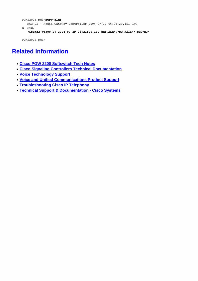
PGW2200a mml>rtrv-alms
MGC-02 - Media Gateway Controller 2004-07-29 06:25:29.451 GMT
M RTRV
"iplnk2-v5300-2: 2004-07-29 06:21:26.180 GMT,ALM=\"SC FAIL\",SEV=MJ"
;
PGW2200a mml>
Related Information
Cisco PGW 2200 Softswitch Tech Notes●
Cisco Signaling Controllers Technical Documentation●
Voice Technology Support●
Voice and Unified Communications Product Support●
Troubleshooting Cisco IP Telephony●
Technical Support & Documentation - Cisco Systems●