phase angle pattern classifier for differential protection...
TRANSCRIPT

Phase Angle Pattern Classifier for Differential Protection of Power Transformers
Ahmed Hosny and Vijay K. Sood Abstract-- Differential relays have been widely adopted in the
protection of large power transformers against winding short circuits. These relays may suffer from false operation in response to magnetizing inrush currents, resulting in major interruption of electric service and sometimes power blackouts. This paper presents a novel approach using a Phase Angle Pattern Classifier (PAPC) to distinguish internal fault currents from other disturbances in power transformers. The PAPC utilizes vector algebra for defining the phase shift between the fundamental components of corresponding line currents. A phase shift greater than a threshold value of 90°is interpreted as an internal fault; otherwise the transformer is considered sound. Unlike existing relaying techniques, the PAPC-based scheme is independent of the transformer equivalent circuit and harmonic contents in the differential current. The proposed approach is verified using an EMTP-RV simulation model of a typical three-phase core-type power transformer. Simulation results indicate that the PAPC-based approach is efficient, stable and secure for classifying transformer operating conditions, fault or non-fault mode.
Keywords: Differential protection, magnetizing inrush current,
phase angle pattern classifier (PAPC), power transformers.
I. INTRODUCTION
OWER Transformers are static devices and vital components of the power system. The chances of faults
occurring on them are rare as they are enclosed and oil immersed. However, occurring of even a rare fault has substantial damage and prolonged power outage consequences unless the transformer is quickly disconnected from the system. This highlights transformers’ importance and, in particular, the importance of reliable and fast protection system from possible faults.
Differential relays are commonly employed for the protection of large power transformers. In such relays, the current on the primary side of a transformer is compared with that on the secondary side. The principle of operation is based Kirchhoff’s current law, i.e. under normal operation, current entering the transformer equals that leaving it. When a difference in current magnitudes exists, it is assumed that the transformer has suffered a fault and it should be disconnected by tripping of the relevant circuit breakers. However, when a transformer is energized, high magnitude magnetizing inrush
Authors are with the Faculty of Engineering and Applied Science,
University of Ontario Institute of Technology (UOIT), 2000 Simcoe St., N. Oshawa, ON L1H 7K4, Canada (phone: 905-721-8668 ext. 5478; e-mail: [email protected]
Paper submitted to the International Conference on Power Systems
Transients (IPST2013) in Vancouver, Canada July 18-20, 2013.
currents may result. These currents are seen by the supply side current transformers (CTs) only and could be interpreted as an internal fault. Precautions must therefore be taken to prevent a differential protection operation due to magnetizing inrush currents. Previously, protection engineers used to rely on a time delay feature built into the relay, i.e. the relay is deliberately made insensitive during energization time. Disabling the relay is, however, a poor practice since any abrupt change in the terminal voltage may drive the transformer core into saturation and magnetizing inrush currents may arise. This has motivated protection researchers to develop different techniques for countering the possibility of differential relay operation for magnetizing inrush currents.
The most common technique for the magnetizing inrush problem is the use of current differential characteristics in combination with the second harmonic restrain [1]-[3].The percentage of the second harmonic to the fundamental frequency component of the differential current is monitored. The differential relay is blocked when the percentage is less than a threshold value, typically, 16%. However, this technique may suffer from false operation as the improved magnetic materials with high-knee points in modern transformers provide inrush currents with low harmonic contents [4]-[5]. In addition, internal fault currents may contain substantial harmonic components due to (a) nonlinear fault resistance and (b) LC resonance in the power system.
Advanced digital signal processing approaches have also been used to avoid the differential relay operation for magnetizing inrush currents. These approaches are based on the pattern recognition using artificial neural networks [6]-[7], fuzzy logic [8] and wavelet transforms [9]. These approaches have limitations that may affect their speed of operation, dependability and security. They also require complex computations and are susceptible to changes in transformer parameters.
In the present work, a new PAPC based algorithm is investigated for identifying magnetizing inrush currents from internal fault currents in the differential protection of power transformers. A three-phase power transformer embedded in a power system fed from both ends is simulated using the EMTP-RV software and subjected to a large number of fault and energization conditions. Differential and restraint current signals are calculated and presented to the proposed scheme to evaluate its performance.
II. METHODOLOGY
A. Power System Model
The proposed protection scheme is tested on a 25 MVA,
P

Fig. 1. One-line diagram of simulated power system.
Fig. 3. Flowchart of percentage differential relay 87T and PAPC scheme.
Fig. 2. Phase shift between the fundamental-frequency components of phase c primary and secondary currents; no fault (green), magnetizing inrush (black), 5% turn-turn fault (red).
138/13.8 kV, 60 Hz, three-phase core-type power transformer with star-star connection and the star point is solidly grounded. The transformer is connected to a 138 kV sub-transmission system on one end and a short transmission line on the other, as shown in Fig. 1. The remote end of the transmission line is connected to a 13.8 kV distribution system. The power transformer is protected against internal faults by a current differential relay (87T) supervised by the PAPC scheme. The 87T relay and the PAPC scheme are coupled to the power system through six Current Transformers (CTs). The secondary windings of the CTs are connected in star and the star point is solidly grounded.
For the studied transformer, the phase shift between the 60-Hz components of the equivalent currents (I1s and I2s in Fig. 1) is simulated using EMTP-RV modules; and it has been found that it is a function of the transformer operating mode. As depicted in Fig. 2, it is almost 0° for no fault, 90° for magnetizing inrush and more than 90° in case of internal faults. With the help of this observation, internal fault currents can be differentiated from the magnetizing inrush currents.
B. Combined Differential Relay and PAPC system
A flowchart of the combined PAPC scheme and biased percentage differential relay of one phase of the power transformer is shown in Fig. 3. The fundamental-frequency components of the CTs secondary currents (I1S and I2S) are extracted and fed to both differential relay and PAPC scheme. In the differential relay module, the differential current Id=I1S - I2S and the restraint current Ir=[I1S + I2S]/2 are evaluated. Then, the percentage differential characteristics are checked to identify the operating condition of the power transformer. Logic “1” is assigned for internal fault/magnetic inrush conditions and logic “0” is used for other operating modes. At the same time, the phase shift θ between I1S and I2S is monitored as described in the next section. Internal fault is declared whenever the phase shift is greater than 90° and logic “1” is issued; otherwise the power transformer is sound and logic “0” is delivered. The outputs from the differential relay and the PAPC scheme are ANDed and a trip signal is released only whenever an internal fault is identified.
C. Phase Shift Calculation
According to the discussion in the previous section, the characteristic curve of the PAPC scheme is a horizontal line displaced vertically by 90° on the theta-time plane. The scheme operates whenever the phase shift θ between the fundamental-frequency components of I1S and I2S exceeds the threshold value of 90°. The operation is irrespective of the magnitudes of the differential and restraint currents. Thus, calculating the exact phase shift between the corresponding currents I1S and I2S is not necessary for discriminating internal fault currents from other transients in power transformer.
The operating principle employed by the PAPC scheme is based on vector algebra where a magnitude comparator is used. The input quantities to the comparator are the magnitudes of the difference and the sum of the fundamental-frequency components of the CTs secondary currents, i.e. |I1S-I2S| and |I1S+I2S| respectively. The PAPC performance is
simply illustrated with the help of three phasor diagrams shown in Fig. 4. The three phasor diagrams are with phase shift θ (a) equal to 90°, (b) less than 90° and (c) greater 90°, respectively. When θ is greater than 90°, the magnitude value

Fig. 4.Phasor diagrams for the PAPC scheme based on magnitude comparator: (a) Magnetic inrush, (b) normal loading and external fault, and (c) Internal fault.
Fig. 5. Single-phase model of a three-phase power transformer for simulation of internal faults and magnetic inrush; ZLV =Z1+Z2+Z3, fault resistance = Rf.
Fig.6. Magnetizing reactance characteristics.
0
100
200
300
400
500
600
0 100 200 300 400 500
Flu
x (V
.s)
Current (A)
of the difference current |I1S-I2S| becomes greater than that of the sum of the currents |I1S+I2S| and the scheme operates. When θ is equal to or less than 90°, the scheme does not operate. This is true irrespective of the magnitudes of the currents I1S and I2S.
The condition that θ is greater than 90° will be satisfied only when the transformer experiences an internal fault where I2S becomes out of phase with its pre-fault direction. In case of magnetizing inrush (high-voltage winding is connected to the source and low-voltage winding is disconnected or lightly loaded), the phase shift θ will be equal to 90° as the magnitude of I1S dominates both the difference and the sum of the currents. During normal operation and faults outside the transformer protection zone, the phase shift θ will be less than 90° since the currents I1S and I2S are flowing in the same direction.
The major concerns for real-time implementation of new digital protective algorithms are the number of computations and the time required to do them. The magnitudes of the difference and the sum of the currents are necessary to meet the objectives of the differential relay and PAPC scheme, and can be computed only once. Thus, the real-time implementa-tion of the proposed scheme is relatively easy as only one conditional IF statement is required for comparing the magnitudes of the difference and the sum of the currents.
III. SIMULATION RESULTS
A. Power System Parameters
In the power system (Fig. 1) modeled using EMTP-RV, the high-voltage and low-voltage sources are represented by equivalent voltage sources behind their respective Thévenin impedances. The short-circuit rating of the 13.8 kV ac source is 75 MVA (R+=1.4 ohms, L+=5.6mH, R0=1.498 ohms, L0=11.975 mH) while that of the 138 kV ac source is 883 MVA (R+=7.1 ohms, L+=53.99mH, R0=7.596 ohms, L0=115.45 mH). A 13.8 kV 5-km short transmission line is represented by a single pi section with parameters: R0=0.1437 ohms, R1=0.3101 ohms, L0=11.45 mH, L1=2.41 mH, C0=5.635 nF and C1=26.8 nF. A model of 138/13.8 kV three-phase
power transformer is represented by a bank of three ideal m-winding elements connected in star-star with the star point solidly grounded. The transformer has a short-circuit impedance of 9% (ZHV=0.908+j29.6 ohms, ZLV=0.0091+j0.296 ohms). Hysteresis and eddy current losses of 16 kW are simulated by a resistor of RC=1.19 MΩ connected across the high-voltage winding of each phase.
Figure 5 shows the necessary arrangement for simulating short-circuited windings and magnetizing inrush in a three-phase power transformer (only one phase shown) [10]. The low-voltage winding is divided into three sub-windings connected in series. The low-voltage impedance ZLV is divided according to the percentage of the sub-winding. Five switches are used in the arrangement to simulate turn-to-turn and turn-to-ground faults. Many cases covering different percentages of short circuit winding at different phases can be conducted. Fault resistance can be managed by varying the value of Rf embedded in the sub-windings.
The transformer model is provided with a non-linear reactor Xm connected across the high-voltage winding of each phase to account for magnetizing inrush current representa-tion. The flux-current (ψ-I) characteristics of the transformer

Fig. 7.Response of PAPC and percentage differential relay to inrush currents; (a) primary currents referred to relay side, (b) differential relay response, (c) PAPC response, (d) combined response of PAPC and 87T relay, (e) locus of Id and Ir with 87T for phase a; phase a (black), phase b
(blue), phase c (green), Ib-HV = 5.23 A, Ib-LV = 4.358 A, Δt=40μs.
magnetic core is depicted in Fig. 6. The magnetizing inrush current is simulated by opening all switches on low-voltage windings and connecting the high-voltage windings to the 138-kV source through closing the circuit breaker CB1. Different inrush waveforms can be simulated by controlling the switching instant of the CB1. Maximum magnitude of inrush currents occurs when the CB1 is closed at the zero-crossing of the voltage waveform.
The current transformers in Fig.5 are modeled with the help of single-phase ideal transformer to represent turns ratio. They belong to 2000/5 C800 CTs, whose parameters are reported by the IEEE power system relaying committee [11]. The CTs on high-voltage and low-voltage sides of the power transformer are set on the taps 100/5 and 1200/5 respectively. The non-linear characteristics of the CT magnetic cores are also taken into account to investigate the response of the proposed algorithm to CT saturation.
B. Percentage Differential Relay Settings
According to the polarity of current transformers (CTs) shown in Fig. 1, the instantaneous differential current id is the difference between corresponding current samples from each CT, i.e.,
�� = ��� − ��� (1) and the instantaneous restraint current ir is the average summation of corresponding current samples from each CT, i.e.,
�� = (��� + ���) 2⁄ (2) The magnitudes of the fundamental frequency components of id and ir, i.e. Id and Ir, are calculated at each sample using the instantaneous-to-phasor EMTP module, which employs a full cycle Discrete Fourier Transform (DFT) to fulfill its function.
The relay uses a single-slope operating characteristic described by,
�� > �. �� + ������� (3)
where k is the slope of the operating characteristic and Ipickup is the minimum pickup current to account for the no-load current of the protected transformer and on-load tap changer. For the results shown in this paper, k and Ipickup are set to 20%.
C. Performance of PACA and 87T Relay
Numerous tests were carried out on the power transformer in Fig. 1 and the performance of the biased percentage differential characteristics along with the PAPC scheme was verified. For different fault and inrush waveforms, the scheme responded accurately according to the simulated case. The PAPC could recognize all internal fault cases regardless of fault inception time, fault type and fault location. In all cases, the simulation was run for a total time period of 100 ms to demonstrate the stability of the proposed algorithm.
An example of inrush waveform is shown in Fig. 7. The power transformer is energized at 16.67ms (at the point of phase-a voltage crossing to positive) while all switches at the
low-voltage windings are kept open. Since the high-voltage winding currents are measurable and those of the low-voltage winding are zero, the 87T relay generates trip signals for phases a, b and c. The trip signals are generated after a quarter cycle of the fundamental frequency voltage. The PAPC of each phase issues logic “0” and blocks the differential relay operation although the magnitude of the inrush current is high for the first few cycles, typically, four times the transformer rated current.
Figure 8 presents the performance of the PAPC scheme along with biased percentage differential relay to a turn-to-ground fault at 20% of phase a low-voltage windings. The fault occurs at 20 ms with zero fault resistance. Both 87T and PAPC have recognized the internal fault currents within a quarter of 60 Hz cycle. Logical output “1” is released for phases a, b and c, and the protected transformer is completely disconnected from the rest of the power system.
(a)
(b)
(c)
(d)
(e) 87T relay trajectory
87T relay settings
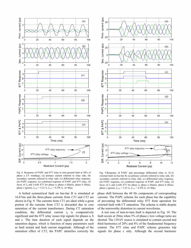
Fig. 8. Response of PAPC and 87T relay to turn-ground fault at 20% of phase a LV windings; (a) primary current referred to relay side, (b) secondary currents referred to relay side, (c) differential relay response, (d) PAPC response, (e) combined response of PAPC and 87T relay, (f) locus of Id and Irwith 87T for phase a; phase a (black), phase b (blue), phase c (green), Ib-HV = 5.23 A, Ib-LV = 4.358 A, Δt=40μs.
Fig. 9.Response of PAPC and percentage differential relay to 3L-G external fault on bus-bar B; (a) primary currents referred to relay side, (b) secondary currents referred to relay side, (c) differential relay response, (d) PAPC response, (e) combined response of PAPC and 87T relay, (f) locus of Id and Irwith 87T for phase a; phase a (black), phase b (blue), phase c (green), Ib-HV = 5.23 A, Ib-LV = 4.358 A, Δt=40μs.
A bolted symmetrical fault on bus-bar B is simulated at 16.67ms and the three-phase currents from CT1 and CT2 are shown in Fig. 9. The currents from CT1 are ideal while a great portion of the currents from CT2 is discarded due to core saturation of the current transformers. During CT saturation condition, the differential current id is comparatively significant and the 87T relay issues trip signals for phases a, b and c. The time duration of each signal depends on the saturation degree, which is function of many parameters such as fault instant and fault current magnitude. Although of the saturation effect of CT2, the PAPC identifies correctly the
phase shift between the 60 Hz components of corresponding currents. The PAPC scheme for each phase has the capability of preventing the differential relay 87T from operation for external fault with CT saturation. The scheme is stable despite of the noteworthy distortion in current waveforms.
A test case of turn-to-turn fault is depicted in Fig. 10. The fault occurs at 20ms when 5% of phase c low-voltage turns are shorted. The 138 kV source is simulated to contain second and third harmonics of 20% and 8% of the fundamental frequency content. The 87T relay and PAPC scheme generates trip signals for phase c only. Although the second harmonic
(a)
(c)
(d)
(e)
(f)
(b) (b)
(a)
(c)
(d)
(e)
(f) 87T relay settings
87T relay trajectory 87T relay trajectory
87T relay settings

Fig. 9. Response of PAPC and percentage differential relay to 5% turn-turn fault on phase c LV windings; (a) primary currents referred to relay side, (b) secondary currents referred to relay side, (c) differential relay response, (d) PAPC response, (e) combined response of PAPC and 87T relay, (f) locus of Id and Irwith 87T for phase c; phase a (black), phase b (blue), phase c (green), Ib-HV = 5.23 A, Ib-LV = 4.358 A, Δt =40μs.
content is higher than the typical setting of harmonic restraint differential relays, the PAPC scheme can identify the fault and disconnect the power transformer within a quarter of 60 Hz cycle.
IV. CONCLUSIONS
A PAPC approach combined with the percentage differen-tial principles is investigated for digital protection of modern power transformers. The approach uses the phase shift between the 60 Hz components of corresponding line currents as a restraint signal to differential relay operation for inrush
conditions. A typical three-phase core-type power transformer is simulated using the EMTP-RV software. Various current waveforms for magnetizing inrush and fault cases are presented to the proposed approach and its performance is analyzed. The simulation results show that the integration of the phase shift between the 60 Hz components of the corresponding currents has substantially improved the reliability of the differential relay. Discriminating internal fault currents from other disturbances in power transformers is efficiently performed within a quarter of 60 Hz cycle. The performance is largely independent of harmonic contents in the differential current, transformer parameters and the effect of CT saturation. The implementation of the PAPC scheme does not require complex computation and can be easily incorporated into existing digital differential relays.
V. REFERENCES
[1] M. A. Rahman and B. Jeyasurya, “A State-of-the-Art Review of Transformer Protection Algorithms,” IEEE Trans. Power Del., Vol. 3, No. 2, pp. 534-544, April 1988.
[2] I. Hermanto, M. Y. Murty and M. A. Rahman, “A Stand Alone Digital Protective Relay for Power Transformers,” IEEE Trans. Power Del., Vol. 6, No. 1, pp. 85-95, Jan. 1991.
[3] L. F. Kennedy and C. D. Hayward, “Harmonic-Current Restrained Relays for Differential Protection,” AIEE Trans., Vol. 57, pp. 262-266, May 1988.
[4] P. Lui, O. P. Malik, D. Chen, G. S. Hope and Y. Guo, “Improved Operation of Differential Protection of Power Transformers for Internal Faults,” IEEE Trans. Power Del., Vol. 7, No. 4, pp. 1912-1919, Oct. 1992.
[5] T. S. Sidhu, M. S. Sachdev, “On Line Identification of Magnetizing Inrush and Internal Fault in Three-Phase Transformers,” IEEE Trans. Power Del., Vol. 7, No. 4, pp.1885-1891, Oct. 1992.
[6] M. R. Zaman and M. A.Rahman, “Experimental Testing of an Artificial Neural Network Based Protection of Power Transformer,” IEEE Trans. Power Del., Vol. 13, No. 2, pp. 510-517, April 1998.
[7] L. G. Perez and et al, “Training an Artificial Neural Network to Discriminate Between Magnetizing Inrush and Internal Faults,” IEEE Trans. Power Del., Vol. 9, No. 1, pp. 434-441, Jan. 1994.
[8] M. C. Shin, C. W. Park and J. H. Kim,” Fuzzy Logic-Based Relaying for Large PowerTransformer Protection,” IEEE Trans. Power Del., Vol. 18, No. 3, pp. 718-724, July 2003.
[9] O. Youssef, “A Wavelet-Based Technique for Discrimination Between Faults and Magnetizing Inrush Currents in Transformers,” IEEE Trans. Power Del., Vol. 18, No. 1, pp. 170-176, Jan. 2003.
[10] D. V. Coury, P. G. Campos, and M. C. Tavares, “Modeling a Power Transformer for Investigation of Digital Protection Schemes,” Proc. Of IEEE/PES, 8th Int. Conf. on Harmonics and Quality of Power, Athens, Greece, pp. 1041-1046, Oct. 1998.
[11] Power System Relaying Committee, “EMTP Reference Models for Transmission Line Relay Testing,” IEEE PES/PSRC, 2005.
Ahmed Hosny received Ph.D. in Electrical Engineering from the University of New York at Buffalo in 2009. From 2009 to 2011, he was an assistant professor at Helwan University, Egypt. He is at present a Postdoctoral Fellow at the University of Ontario (UOIT), Oshawa.
Vijay Sood is an associate professor and the NSERC-OPG Design co-chair at UOIT, Oshawa, Ontario. He has extensive experience in HVDC and FACTS and their controllers. His research focuses on the monitoring, control, and protection of power systems and on the integration of renewable energy systems into the smart grid. He is a registered professional engineer in the province of Ontario. He is a Fellow of the IEEE, the Engineering Institute of Canada and the Canadian Academy of Engineering. He is an editor of the IEEE Transactions on Power Delivery, and co-editor of the IEEE Canadian Journal of Electrical and Computer Engineering.
(a)
(b)
(c)
(d)
(e)
(f)
87T relay settings
87T relay trajectory