ph.d thesis proposal: distributed diversity in hybrid wireless
TRANSCRIPT

Ph.D Thesis Proposal:Distributed Diversity in Hybrid Wireless Networks
Yin WangCollege of Computer and Information Science
Northeastern UniversityBoston, MA, 02115
November, 2009

Contents
1 Introduction 2
2 System and Approach 3
3 Distributed Signal Combining 53.1 Background and Motivation . . . . . . . . . . . . . . . . . . . . . . . . . . . . . . . . 53.2 Hierarchical Priority Combining (HPC) . . . . . . . . . . . . . . . . . . . . . . . . . 63.3 Performance Analysis and Preliminary Results . . . . . . . . . . . . . . . . . . . . . 8
4 Distributed Traffic Multiplexing 134.1 Background and Motivation . . . . . . . . . . . . . . . . . . . . . . . . . . . . . . . . 144.2 Model . . . . . . . . . . . . . . . . . . . . . . . . . . . . . . . . . . . . . . . . . . . . 144.3 Stationary Regime for Blocked-Poisson Traffic, Exponential Service Time . . . . . . 154.4 Traffic Pattern . . . . . . . . . . . . . . . . . . . . . . . . . . . . . . . . . . . . . . . 164.5 Prototype and Experimentation for Distributed Link Bonding Cooperation . . . . . 194.6 Transport Layer Optimization . . . . . . . . . . . . . . . . . . . . . . . . . . . . . . . 21
5 Future Work and Timeline 21
1
1 Introduction
Wireless communication networks are enabling an ever increasing set of applications. This set spansdomain areas such as traditional telephony, ubiquitous access to information and computation,cyber-physical infrastructure monitoring, and disaster recovery. The service quality and scalabilityof these applications is limited by fundamental constraints. These include a scarce radio-frequencyspectrum, signal propagation effects such as fading and shadowing resulting in areas with limitedcoverage, and the small form factor of mobile devices with limited capability to store energy.The current solution adopted by operators is to deploy additional base stations [1]. However,this strategy is ineffective and costly. In this thesis, we propose to explore a new communicationmodel, where multiple mobile nodes cooperate with each other and with the base stations. We willinvestigate communication strategies that exploit the channel and traffic diversity across a set ofcooperating mobile nodes equipped with multiple radio interfaces (e.g., cellular and WiFi).
The networking architecture and software protocol stack of current wireless systems have fun-damental limitations in addressing the unique characteristics of wireless communications such asshared medium, signal fading and shadowing, and interference. In the case of cellular networks,although various new techniques have been introduced in the third generation systems, and havebeen deployed for several years, quality of service is still lacking, and problems such as droppedcalls, dead spots, and slow network speed are still very common. According to a recent survey [2],55% of smart phone users are not satisfied with the network services and are experiencing a highpercentage of dropped calls and slow Internet speed (also reported in [3, 4]). Other documentsreport a dropped call rate as high as 30% in some urban areas [5, 6]. These problems consti-tute a critical research challenge because of the trends of increased bandwidth demand of futureapplications.
Diversity and cooperation, as general mechanisms to increase the robustness and efficiency ofwireless communication systems, have been studied for many years [7, 8, 9, 10], but very littleresearch has been done on distributed cross-layer systems with multiple types of air-interfaces (e.g.,GSM, HSPA, WiMAX and IEEE802.11) and considering the unique characteristics of each of theinterfaces. With increased hardware integration, faster computation, and high users density, thecooperation between nearby devices is becoming possible and even necessary given the increaseddemand for bandwidth.
This thesis’ research aims at developing a framework for cooperation across multiple networklayers to improve robustness, throughput, and delays. We focus on a specific heterogeneous net-work with devices equipped with two types of radio frequency (RF) interfaces: a short-range highdata-rate interface (e.g., WiFi), and a long-range low data-rate interface (e.g., cellular). Withinthis framework, we propose and evaluate a set of distributed cooperation techniques operating atdifferent hierarchical levels with various resource constraints. The proposed cooperation is basedon two loosely-coupled strategies: signal combining and traffic multiplexing. As a first step, wepropose to investigate them separately because they exploit different types of diversity: channeldiversity and traffic diversity. The long term goal of this research is to understand how they canbe used simultaneously.
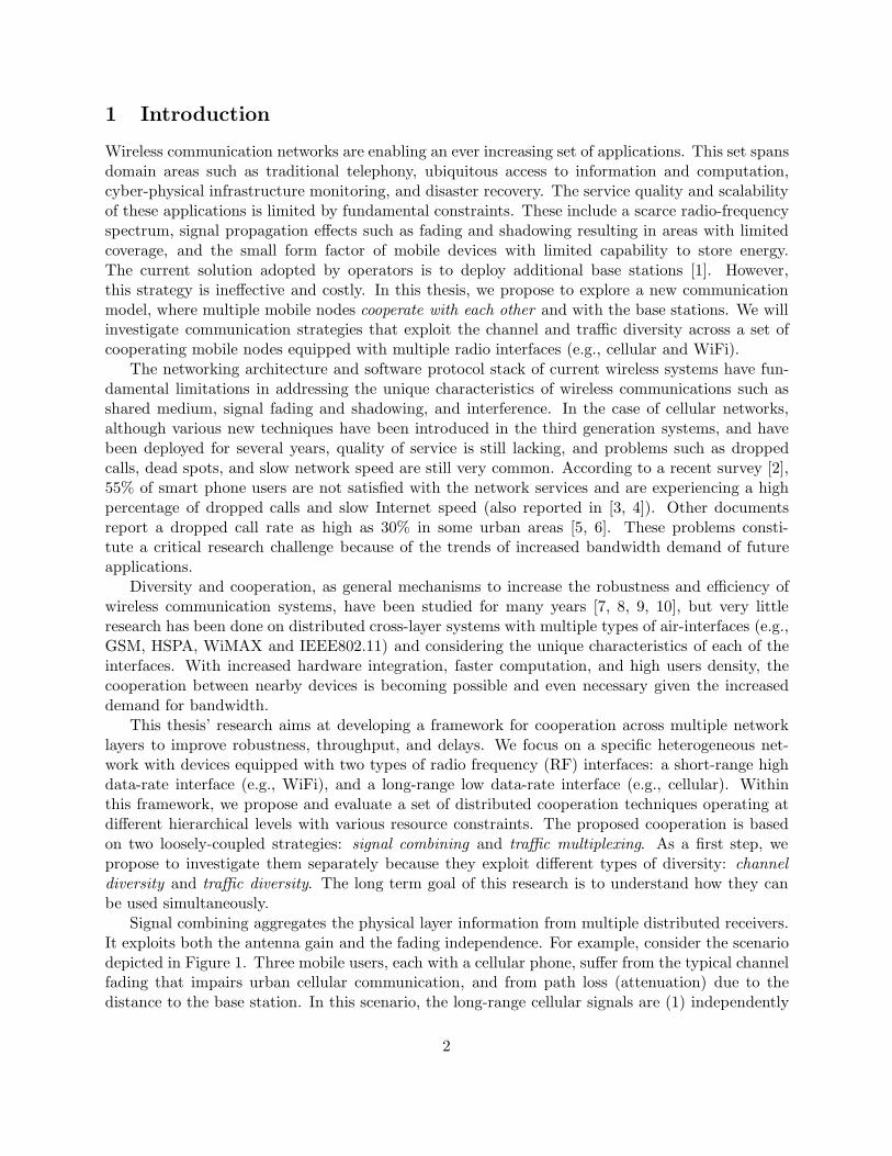
Signal combining aggregates the physical layer information from multiple distributed receivers.It exploits both the antenna gain and the fading independence. For example, consider the scenariodepicted in Figure 1. Three mobile users, each with a cellular phone, suffer from the typical channelfading that impairs urban cellular communication, and from path loss (attenuation) due to thedistance to the base station. In this scenario, the long-range cellular signals are (1) independently
2

received at the three nodes, (2) relayed through the high speed local wireless network, and (3)combined at the destination node. This cooperation can significantly improve the Signal to NoiseRatio (SNR), Bit Error Rate (BER) and throughput. It leads to improved coverage and a capacityboost. Furthermore, it reduces interference as the base stations do not have to increase theirtransmission power to overcome the channel fading in order to reach mobile nodes.
Traffic multiplexing, on the other hand, bundles the capacity of long-range cellular links toform a high throughput link. It exploits both traffic and channel diversity to achieve a higherthroughput and better bandwidth utilization. For example, when multiple users contend to accessthe web through cellular networks, most of the time, their long-range cellular links are not used,and even if they are simultaneously browsing the probability that two users are simultaneouslydownloading is small (because of the time users take to read and think about downloaded content).Therefore, multiplexing the users traffic over a distributed bonded link can result in significantperformance improvement.
The proposed framework provides a flexible and dynamic way to adopt different diversity coop-eration techniques based on the channel conditions and short-range RF bandwidth limitations. Therest of the proposal is organized as follows. Our approach and framework is described in Section 2.In Section 3, we propose a hierarchical signal/packet combining technique that exploits the channeldiversity. In Section 4, we propose a distributed link-bonding system that takes advantage of trafficdiversity and multiplexing. Finally in Section 5, we discuss the future work and provide a timelinefor the proposed research.
BSC
MS3
MS2MS1
BTS1
BTS2
BTS3
Backbone
Web Server
Wired Communication
Wireless Long-Range CommunicationWireless Short-Range Communication
Figure 1: Example of setup for distributed cooperation framework
2 System and Approach
We consider a hybrid network where the mobile nodes are equipped with two radio communicationinterfaces: a cellular long-range low data-rate interface, and a short-range high data-rate interface.Our distributed cooperation strategy includes two basic approaches: signal combining and trafficmultiplexing. This cooperation strategy is transparent to applications; therefore, the existing ap-plications would have an improved performance without requiring any awareness or modification.
3

In the following, we outline the key mechanisms, design, and constraints of the proposed system.
Diversity: The performance of long-range cellular links is limited by the shadowing and channelfading caused by multipath propagation and mobility. These are critical problems in cellular com-munication as they result in dead-signal areas and localized poor system performance. RF-channeldiversity is a typical approach to overcome them through independent transmission paths. Manyexisting technologies, such as MIMO, require multiple antennas to be co-located at the same de-vice. But, due to the minimum spatial separation (0.4λ [9]) and high cost of RF front ends, it ishard to implement these schemes on a single small form factor device such as a cell phone [11].Our cooperation strategy intends to take advantage of the RF front ends of a set of geographicallydistributed devices.
A limiting factor of the long-range cellular communication is its relatively low data-rate. Usersof mobile phones usually make one request at a time (e.g., browse a web page and wait until it iscompletely loaded before making a new click). This results in an imbalanced traffic and unusedbandwidth. However, neighbouring nodes could take advantage of this traffic diversity by poolingtheir links together through the high-speed short range communication interface and benefit fromtraffic multiplexing. This results in an improvement of the actual throughput experienced by usersand the overall network utilization.
Distributed Cooperation Framework: In our proposed setup, a Base-Transceiver-Station BTS1
is communicating with a Mobile-Station MS1 and another Mobile-Station MS2 is in the vicinity(See Figure 1). On one hand, each of the mobile stations are physically separated with reasonabledistance, so the links such as BTS1 to MS1 and BTS1 to MS2 are independent transmission channels.On the other hand, all of the mobile stations are connected to their own cellular networks. Theymight be serviced by different operators, working on different frequency bands, or time slots, suchthat each of them can transmit at a certain rate. As a result, both channel diversity and trafficdiversity can be exploited.
We propose a distributed cooperative framework to utilize these diversity gains on existingcellular systems. This framework consists of the following 3 strategies.
• Signal Combining. In this cooperation strategy, which is usually implemented in the phys-ical layer, signals are being received by all nodes in cooperation; the assisting nodes forwardthe received signals to the master node, and the master node combines all the data to correcttransmission errors. By exploiting the channel diversity gain and antenna gain, signal com-bining can significantly improve the network robustness and capacity. A limitation of thisapproach is that it requires the modification of the physical layer and devices hardware.
• Traffic Multiplexing. In this cooperation strategy, the cooperating nodes bundle theirlong-range links together to form a high speed link with aggregated capacity. The traffic fromeach node is spread among the links of all cooperating nodes (in other word, multiplexed inthis bundled link). The advantage of adopting this strategy is that it provides load balancingand therefore achieves a higher network utilization, improves the robustness and perceivedthroughput through both traffic diversity and channel diversity. Further more, this approachcan be implemented as a software middleware in the network layer, and has no impact on thephysical layer and device hardware.
4
• Cross-Layer Cooperation. Signal combining and traffic multiplexing are orthogonal strate-gies, so they can be adopted independently. It is also possible to incorporate both to allowinteractions between them. In this cross-layer cooperation, traffic scheduling can be based onthe channel knowledge. The traffic scheduler decides who should be included in the coopera-tion and how the traffic is being routed. For example, if one node sends a packet corruptedduring the transmission, the re-transmission packet can be rerouted through another cooper-ating node with best channel conditions and possibly with a different coding scheme. Becauseof the resulting complexity of such coupling, and as a first step, our immediate research fo-cuses on the previous two basic cooperation strategies. In the future, we will investigate thegeneral cross-layer cooperation.
System Constraints: The existing techniques introduced in the past (e.g., Maximum RatioCombining, and Generalized Selective Combining [12, 7, 9]) were designed for antennas that arewired to a central combiner and not restricted by the local communication limitations.
The proposed cooperation strategies require the nodes to forward or relay information to othernodes through a local wireless networks. This raises interesting questions on how to maximize thesystem performance while meeting the constraints of the short-range network bandwidth, compu-tation and energy consumption. Given that the local bandwidth is shared with other nodes andlocal communications can also consume a significant amount of energy, it is critical to minimizethe usage of the local bandwidth. This research aims at developing several cooperation techniquesthat improve the long-range communication performance while accounting for the local bandwidthconstraints.
3 Distributed Signal Combining
In this part of the research, we propose to study the signal combining strategy. In the followingsections, we discuss this type of cooperation in a hybrid networks with long-range low data-ratelinks and short-range high data-rate links, introduce a distributed cross-layer channel diversitytechnique - Hierarchical Priority Combining (HPC), and present our preliminary analysis results ofthe proposed techniques. The metrics include outage probability, bit error rate, and throughput.
3.1 Background and Motivation
Cellular systems are designed for long-range and relatively low data-rate communications. Be-cause of long distance, no line-of-sight, and mobility, they suffer from strong multipath fading andshadowing [8]. Recently due to the increasing demand of mobile services such as mobile cloudcomputing and video streaming, improving the robustness and throughput of cellular systems hasbecome more critical. Simple solutions for reducing the bit error rate by increasing the transmis-sion power would cause more interference and result in adversely reducing the system capacity;an alternative solution is to bring the cellular base stations closer to the mobile clients, but thisrequires a deployment of more base stations which is not economical and difficult to scale.
Diversity is an efficient and powerful tool to mitigate channel fading and shadowing [9, 10].Most of the previous work on pre-demodulation diversity focuses on combining techniques usingmultiple antennas that are co-located on a single device. Given that all the antennas are directlyinterconnected, the combining algorithms have full access to the signals from all the antennas.
5

However, co-locating multiple antennas on a single mobile device is impractical for the moderncellular systems. This is not only due to the form factor limitation and cost, but also because ofthe spatial separation needed between the antennas to achieve channel independence.
Recently, distributed cooperation has attracted more interest from the wireless communicationsand networking research community [13]. Some studies have addressed specific cases such as diver-sity with homogeneous interfaces where the combining occurs over the air [11, 14, 15, 16, 17, 18, 19].Several interesting approaches demonstrate the benefits of distributed cooperation in ad hoc net-works with homogeneous wireless interfaces and challenged the community to investigate the fullbenefits of distributed cooperation [20, 21, 22, 23, 24, 13]. Distributed MIMO in ad hoc networkhas also been theoretically studied in [25, 26]. The use of cooperating heterogeneous air-interfaceswas advocated in [27, 28]. More recently, several post soft-demodulation techniques were proposedfor homogeneous air-interface systems [29, 30]. In our proposed research, we are interested indistributed cooperation with heterogeneous air-interfaces.
Nowadays, most smart-phones are equipped with a short-range high-speed local WiFi interfacesbesides their long-range low data-rate cellular interfaces. Here, the high speed local network makesthe distributed cooperation with a small group of nearby users possible. On one hand, the distanceof cooperating users is close and usually within one hop of short-range radio communications. Sincethe local links are much faster and more reliable than the long-range cellular links, neighbouringnodes can relay their received signals through the local high-speed wireless network. Signals areeventually combined at the destination node to correct errors. On the other hand, users are alsowell separated by meters which allows an independent transmission path from the cellular tower toeach of the users. As a result, it is possible to implement the distributed cooperation to exploit bothof the antenna gain and the diversity gain. Furthermore, as wireless channel fading usually impactstransmission paths fairly independently from other paths, intuitively, only a few cooperative nodeswould be sufficient to correct transmission errors caused by fading. This is confirmed by our analysisresults. In such a cooperative system, because the received data needs to be transmitted throughthe local wireless network, its bandwidth becomes a constraint. First, the cooperation traffic needsto fit within the available local bandwidth. Further, local communications can also cause significantamount of energy and computation, which are critical to the battery powered devices. Minimizingthe amount of local communications and computation as well as achieving most of the cooperationgain are the underlying design principles of the cooperation strategies.
In this section, we introduce a distributed signal combining strategy: Hierarchical PriorityCombining (HPC). In the following, we outline the HPC strategy and present our preliminaryresults.
3.2 Hierarchical Priority Combining (HPC)
HPC incorporates three levels of combining techniques that have different error correction capabil-ities and local bandwidth requirements. We first outline the three basic combining techniques anddescribe the proposed Hierarchical Priority Combining protocol.
• Decode-and-Forward combining: if at least one of the assisting nodes can demodulatethe packet and verify its integrity, then the decoded packet can be relayed to the master nodethrough its short-range link. This level of combining uses the minimum local bandwidth,but can only be used when the overall signal strength is high and the mobile nodes areexperiencing strong uneven fading or shadowing. This could be the case of a group of moving
6
people in a car, bus, or train. A similar idea was discussed in [15]. The main difference here isthat we are considering relay the packet through a different interface rather than re-injectingit back to the same channel with a different coding scheme. We believe that our approach ismore realistic from a system perspective, it however requires a different type of analysis.
• Post Soft-Demodulation combining: at this level, the signal received by the assistingnodes is already strong enough for demodulation but still has a significant number of errors.In this case, some of the assisting nodes, with the strongest received signals, send the soft-decision output of the demodulator to the master node. Combining at this level can be veryefficient at correcting errors when the signal strength is relatively high. This is still a sub-optimal diversity combining technique but has the advantage of requiring only a moderateshort-range communication bandwidth.
• Pre-Demodulation combining: at this level, some of the assisting nodes transmit thesampled down-converted RF-signal to the master node. We introduce Priority MaximumRatio Combining (denoted PMRC) as a candidate for Pre-Demodulation combining. PMRCdictates that only the assisting nodes with the strongest SNR relay their received signalsto the master. The master then combines its received signal with other gathered signals.Signal combining at this level gives the best error correction capability, but communicatingthe digitized waveform information requires a large local bandwidth. Therefore, it is moreappropriate in scenarios where the long-range radio signal is extremely weak and experiencesstrong fading while the local short-range radio is very fast and stable.
The HPC protocol dynamically decides which of the above 3 combining techniques to use atthe time of receiving a packet. Intuitively, pre-demodulation combining takes all the informationof the originally received signals among the cooperative nodes, so it should perform the best inerror correction, but it also requires a huge amount of local bandwidth. Decode-and-Forwardcombining and Post Soft-Demodulation combining can be taken as the light-weight version of Pre-Demodulation combining as it either sends the complete demodulated data or partially demodulatedsoft decision values. The advantage of Decode-and-Forward combining is that it uses a minimalamount of local bandwidth, but requires some node to have a strong signal reception in order toindependently and successfully decode the packet. Post Soft-Demodulation combining, on the otherhand, performs better due the freedom of soft decision values from multiple sources comparing toDecode-and-Forward combining. To achieve the best performance while still minimizing the localbandwidth, our HPC strategy uses the received signal quality to decide which combining techniqueto adopt for each packet. There are many possible ways to cooperate, but the proposed HPCstrategy is effective and easy to implement due to its simplicity and hierarchical structure.
The HPC cooperation protocol runs in two phases. Phase I is a very short period, within whichthe nodes exchange information with each other about the quality of received signals. In phaseII, each node decides if and what level of combining information it will send to the master. Inthe following, we provide a high-level description of the protocol. M is the total number of nodesinvolved in the cooperation. N is the number of signal sources involved in combining. Note thatsince the cooperation always includes the master node, N − 1 is the actual number of distributedassisting nodes that relay their signals to the master node.
Phase I: The master node broadcasts a cooperation request beacon if it is unable to decode thepacket. Upon receipt of the cooperation-request beacon, the assisting node measures the SNR of thereceived signal (denoted by γ) from the long-range air interface and compares it with a predefined
7

threshold γD . (γD is the threshold above which demodulating the packet is feasible.) If γ < γD theassisting node just broadcasts the SNR to others. If γ > γD , it will try to demodulate the packetand verify its integrity using a CRC-like checksum. Finally, the assisting node will broadcast boththe SNR and the CRC verification result. Each node is assigned to a particular time slot duringthe phase I to avoid collision.
Phase II: In this phase each node makes a decision after hearing other assisting nodes’ reportof signal quality. If at least one assisting node can demodulate the long-range RF signal and alsopass the CRC check, one of them with the highest ID will relay the decoded packet to the master.If no one passes the CRC check and the total number of assisting nodes with γ > γD is morethan a predefined value, the top Nsoft − 1 nodes with the strongest SNR transmit, in the orderof their ID, their soft decision values to the master for Post Soft-Demodulation combining, andthe transmission size Nsoft − 1 is limited by the local bandwidth. Last, if none of the above caseshappen, the top Npre − 1 nodes with strongest SNR send the sampled long-range radio waveformto the master for Pre-Demodulation combining. Npre is also limited by the local bandwidth. Nsoft
and Npre are usually different, depending on system parameters. For simplicity of notation, in thefollowing discussion we may use N to represent either of them. From our following analysis, wewill see that N can be much smaller than M , and it still achieves most of the combining gain.
3.3 Performance Analysis and Preliminary Results
Our preliminary research focuses on the Priority Maximum-Ratio Combining (PMRC) technique, animplementation of Pre-Demodulation combining scheme. We will also investigate the performanceof Decode-and-Forward combining and Post Soft-Demodulation combining in our future work. Ourmetrics includes outage probability, bit error rate, and throughput. We also optimize variousparameters such as the frame size to characterize the maximum goodput of the system.
In the PMRC scheme, a subset of the assisting nodes with strongest SNR relay their signalsto the master, and combine with the signal received at the master node. Since the master’s signaldoes not need to be transmitted over the air, it does not require any bandwidth consumption. Forease of analysis, we first introduce SPMRC, which is a special case of PMRC, where the signals arecombined without the master’s contribution. Then we will use SPMRC to derive the performanceof PMRC.
Consider a system of one base station and M cooperating mobile stations including a masternode. For every packet (or time slot) PMRC consists of identifying the N − 1 strongest signals outof the M − 1 cooperating neighbours and combining their sampled signal with the signal receivedby the master node (destination) before demodulation. The selected signals are aggregated usingMaximum Ratio Combining (MRC) [7, 9, 10]. In the following we denote by (M,N)-PMRC ascheme where the master’s signal is combined with the signal from N − 1 cooperating neighbors.The non-cooperative mode is therefore identical to (M, 1)-PMRC and the traditional M -MRC(MRC with M branches) is identical to (M,M)-PMRC. We will show that (M,N < M)-PMRC(e.g. M = 5,N = 3) are the most interesting schemes that benefit from distributed diversityat low bandwidth/energy cost. In order to study the performance of PMRC, we first study thedistribution of the combined SNR. This allows us to compute the outage probability and also theBER of the combined signal. The BER allows us to derive the Frame Error Rate (FER) and finallythe system throughput. We analyse the SNR distribution of PMRC in two steps. First, we derivethe probability distribution function of the combined SNR of the N − 1 strongest assisting nodes(which we call (M,N)-SPMRC) and then calculate the probability distribution function of the SNR
8

of the master node combined with the N − 1 strongest nodes.
Channel ModelWe consider a typical channel propagation model for cellular communications - Rayleigh chan-
nel [9]. We assume that frame can be delayed and aligned at the destination node for constructivecombining using the techniques such as synchronization patterns. In this model, the probabilitydistribution function of the signal to noise ratio (SNR denoted by γ) as a function of the long runaverage SNR (denoted by γ̄).
p(γ) =
{1γ̄ e−
γγ̄ , γ ≥ 0
0, else
p(γ ≤ t) =∫ t
0
1γ̄
e−γγ̄ dγ = 1 − e−
tγ̄
Since the nodes are spatially separated beyond several wavelength, it is reasonable to assumethat the fading channel for each node is independent and identically distributed (i.i.d.) with thesame noise power spectral density N0/2. The probability that the signals received by all nodeshave an SNR less than t is obviously:
p(γ1 ≤ t, · · · , γM ≤ t) = p(γ1 ≤ t) · · · p(γM ≤ t) = (1 − e−tγ̄ )M
SPMRC: SNR Distribution for N=1, 2, 3Let (M,N)-SPMRC, be the combined signal of the N strongest assisting nodes excluding the
master node. As a first step to derive the SNR probability density function (pdf) of PMRC, wederive the pdf of SPMRC. The combining of these N signals is based on the traditional MRCtechnique.
In the case of (M, 1)-SPMRC, the master collects the strongest signal of the M neighboringnodes. This is traditionally known as Selective Combining [9]. Let X denote the random variablefor the highest SNR among all M neighbors.
pX (x) = p(one node has γ = x) ×p(all the rest M − 1 nodes have γ ≤ x)
pX (x) =M
γ̄e−
xγ̄ (1 − e−
xγ̄ )M−1
In the case of (M, 2)-SPMRC, the master collects the two strongest signals from the M neigh-boring nodes. Let X denote the random variable for the highest SNR among the M cooperatingnodes, and Y denote the random variable for the second highest SNR. The joint probability densityfunction for the two random variables is:
pX,Y (x, y) =
Mγ̄ e−
xγ̄ (M−1)
γ̄ e−yγ̄ ×
(1 − e−yγ̄ )M−2, x ≥ y
0, else
9

Applying MRC to the two strongest signals X and Y gives, γΣ = X + Y [12]:
pγΣ(γ) =
∫ γ
0pX,Y (γ − y, y) dy
=M(M − 1)e−
γγ̄
γ̄×
(γ
2γ̄+
M−2∑
i=1
(−1)i
i
(M−2i
)(1 − e−
iγ2γ̄ )
)
In the case of (M, 3)-SPMRC, the master collects the three strongest signals from the M neigh-boring nodes. Let X be the random variable for the highest SNR in M nodes, Y be the randomvariable for the second highest SNR, and Z be the random variable for the third highest SNR. Thejoint probability density function of the three random variables is:
pX,Y,Z (x, y, z) =
Mγ̄ e−
xγ̄ (M−1)
γ̄ e−yγ̄ (M−2)
γ̄ e−zγ̄ ×
(1 − e−zγ̄ )M−3, x ≥ y ≥ z
0, else
According to the MRC, γΣ = X + Y + Z[12]. Therefore,
pγΣ(γ) =
∫∫
Dy,z
pX,Y,Z (γ − y − z, y, z) dy dz
=12M(M − 1)(M − 2)(
1γ̄
)3e−γγ̄
(γ2
6+
M−3∑
i=1
(−1)i
i
(M−3i
)((1 − e−
iγ3γ̄ )(γ̄γ − 3γ̄2
i) + γ̄γe−
iγ3γ̄
))
PMRC: SNR Distribution for N=2, 3, 4In PMRC, the master node always combines its own received signal with the N − 1 strongest
signals from the neighboring nodes. Using its own signal does not result in any local bandwidth orenergy consumption and always improves the combined SNR. Let γ
Σ′ denote the SNR obtained bythe complete PMRC at the master node: γ
Σ′ = γΣ + γ.Since the probability distribution of the sum of two independent random variables is the convolu-
tion of two random variables’ pdf, for N = 2, 3, 4 of PMRC we have pγΣ′ (γ) =
∫ γ0 pγΣ(τ) · p(γ − τ) dτ ,
where pγΣ was derived in the previous section. Computing the SNR pdf for higher values of N isharder to obtain analytically in a closed form formula. However, we will show that small values ofN are sufficient to obtain most of the diversity gain.
Outage ProbabilityOutage probability is a commonly used measure to evaluate the performance of communica-
tion systems. Assume that γ0 is the minimum signal to noise ratio that can be tolerated bythe decoding/demodulation scheme. Outage probability is defined as Pout(γ̄) = pγ
Σ′ (γ ≤ γ0) =∫ γ0
0 pγΣ′ (γ) dγ, where γ̄ is the average SNR. Figure 2, shows the performance of (5,N) PMRC for
N = 2, to 4 and compares it to the non-cooperative scheme and the traditional MRC. For thesame outage probability (5, 2)-PMRC results in a significantly high energy saving (i.e., the valueof required γ̄) against non-cooperative scheme. For example, for a target Pout = 10−2, the averagetransmission energy can be reduced by more than 17dB, which is 50 times low energy. Even higher
10

saving can be achieved for lower values of Pout. One can note that most diversity gain is alreadyachieved using (5, 4)-PMRC in comparison with the traditional MRC. From this graph we concludethat most of the benefit of the traditional MRC can be achieved by requesting the samples of veryfew neighbors as long as we focus on the strongest signals. Therefore, PMRC can accommodatethe limited short-range bandwidth and still provide most benefit of the traditional MRC.
-5 0 5 10 15 2010log10!Γ""Γ0#
1
10"2
10"4
10"6
Pout
No!Cooperation!5,2"!PMRC!5,3"!PMRC!5,4"!PMRC5!MRC
Figure 2: Outage Probability of PMRC (N =2, ..., 4) vs. MRC and No-Cooperation.
-7.5 -5 -2.5 0 2.5 5 7.5 1010log10!Γ""Γ0#
1
10"2
10"4
10"6
Pout
!5,3"!PMRC!6,3"!PMRC5!MRC!7,4"!PMRC!8,4"!PMRC7!MRC
Figure 3: Impact of M on the performance ofPMRC.
We also studied the impact of the number of cooperating nodes on the outage probability.Figure 3, shows that increasing M dramatically reduces the outage probability. For example,although 5-MRC outperforms (5, 3)-PMRC, increasing M by 1 gives (6, 3)-PMRC which not onlyoutperforms 5-PMRC (by 2dB at Pout = 10−7) but also requires only 2 cooperating nodes to sendtheir contribution instead of 4 nodes in the case of 5-MRC. Therefore 5-MRC requires 100% morebandwidth for lesser performance than (6, 3)-PMRC. A similar improvement in outage probabilityand bandwidth requirement can be observed when comparing 7-MRC to (7, 4)-PMRC and (8, 4)-PMRC. 7-MRC requires 6 cooperating nodes to send their contribution while (8, 4)-PMRC onlyrequires the top three to contribute.
From the many comparisons we carried, we observe that when the average SNR increases,(M ′, 1) will eventually outperform M -MRC (or any (M,N) − PMRC)) as long as M < M ′. Notethat M -MRC (i.e., MRC with M branches) is identical to (M,M)-PMRC.
Bit Error RateBit Error Rate (BER) is another important measure of the performance of wireless communi-
cation systems. To actually compute the BER, we have to consider the specific modulation, codingschemes, and Eb/N0. In the following we consider the coherent Minimum-Shift Keying (MSK)modulation, which is similar to GMSK used in GSM system, with uncoded communication. Wealso assume a pulse shaping transmission with bit duration equal to 1/W such as raised cosinepulses 1 with β = 1 (where W is the used frequency bandwidth). Therefore Eb/N0 = γ and theBER = Q(
√2EbN0
) = Q(√
2γ). These are commonly used assumption for estimating the BER ofcommunication systems [9].
1Similar to sinc(), but it is widely used in practice [7].
11

0 5 10 15 20 25Γ#b!dB#
10"1
10"3
10"5
10"7
10"9
P#b
No!Cooperation!5,2"!PMRC!5,3"!PMRC!5,4"!PMRC5!MRC
Figure 4: Bit Error Rate of coherent MSKdemodulator under PMRC (N = 2, ..., 4) vs.MRC and No-Cooperation.
0 2 4 6 8 10 12 14Γ#b!dB#
10"1
10"3
10"5
10"7
10"9
P#b
!5,3"!PMRC!6,3"!PMRC5!MRC!7,4"!PMRC!8,4"!PMRC7!MRC
Figure 5: Impact of M on the performance ofPMRC in terms of Bit Error Rate.
We first compare the performance of PMRC to the non-cooperative mode and to the traditionalMRC. The BER performance of PMRC is consistent with the outage probability. Figure 4 showsthat for a target BER of 10−3, (5, 2)-PMRC requires 20dB (100 times) less power and with thecontribution from only one cooperating neighbor. Higher gains are achievable when the targetBER is lower. Most of the gain of MRC is obtained using the 2 to 3 strongest neighboring signals.Figure 5, shows the impact of increasing M . Similarly, to the outage probability, increasing thenumber of cooperating nodes outweighs the benefit of increasing N the number of nodes whoare effectively sending their contribution. Notice that the improvement of the BER will directlytranslate to the Frame Error Rate (FER = 1 − (1 − BER)L, where L is the packet size).
Throughput AnalysisDue to the nature of wireless communications packets usually contain error detection code and
forward error correction (FEC) code to counter the data transmission errors. Error detection iscommonly considered as a necessary part of the packet, because it enables the verification of theintegrity of the packet. At the link layer it is usually implemented using a Cyclic RedundancyChecksum (CRC) which allows to detect most errors at the expense of a small overhead. On theother hand, FEC codes are able to correct a small number of errors but with a higher overhead.Signal combining can make such scheme even more efficient. As we will see next, it has a verypromising performance gain even with low BER and unlike FEC it adds zero overhead to thelong-range communication link.
To calculate the precise throughput performance of PMRC, we only consider the overhead ofCRC (32 bits in this case) necessary for packet error detection. Because this overhead is amortizedover the whole packet, the packet size has also an impact on the net throughput. To comparethe various PMRC schemes with fairness, we use the packet size that maximizes the normalizedthroughput:
Throughput =(L − OH)(1 − BER)L
L
where OH denotes the CRC length.
12

1 2 30
0.2
0.4
0.6
0.8
1
N
Thro
ughp
ut
Eb/N0=1Eb/N0=4Eb/N0=7Eb/N0=10
(a) M = 3
1 2 3 40
0.2
0.4
0.6
0.8
1
N
Thro
ughp
ut
Eb/N0=1Eb/N0=4Eb/N0=7Eb/N0=10
(b) M = 4
1 2 3 4 50
0.2
0.4
0.6
0.8
1
N
Thro
ughp
ut
Eb/N0=1Eb/N0=4Eb/N0=7Eb/N0=10
(c) M = 5
Figure 6: Throughput in different cooperation scenarios and Eb/N0(dB)
Figure 6 shows that the throughput of the master node can be tremendously increased by signalcombining with a limited number of cooperation nodes. We also find that PMRC gives comparableperformance of MRC by using fewer active branches. For example of N = 3 and M = 5, besidesthe master’s branch it uses only two active branches out of the four external diversity branches,but it can achieve more than 90% the performance given by MRC with a fairly low Eb/N0 (4 orabove) while it uses only half of the bandwidth required by MRC. It still maintains at least 65%throughput with a very low Eb/N0 at value 1.
Local bandwidth requirementTo compute the local bandwidth requirement, we consider a 2-level HPC strategy which consists
of Decode-and-Forward combining and Pre-Demodulation combining. The local bandwidth can becomputed by considering three cases. First, the master can correctly decode the frame/packet (thisoccurs with probability 1 − FER). In the second case, the master is unable to decode the packetbut at least one of the M − 1 assisting nodes is capable of decoding it (this occurs with probabilityFER ∗ (1 − FERM−1)). Finally, in the third case PMRC combining has to be done and the Nassisting nodes with the strongest signals have to send their sampled signals (this happens withprobability FERM ). Thus, the average local bandwidth requirement is:
Avg − Throughputshort−range = FER × (1 − FERM−1) + N × R × FERM
where R denotes the number of bits required from each assisting node for the combining. R canbe equal to 8 in the case of a non-coherent decoding or soft decision combining, and as high as 96bits for coherent decoding (4 over-sampling factor, 12 bits quantization for I and Q).
4 Distributed Traffic Multiplexing
In this section, we propose to study a distributed network-layer traffic-multiplexing strategy: Dis-tributed Link-Bonding (DLB). We first motivate the benefits of traffic multiplexing and link-bonding techniques; then introduce the model used in the analysis; present the preliminary an-alytical and simulation results; finally we discuss several implementation schemes, prototyping andoptimization.
13

4.1 Background and Motivation
Nowadays, a variety of mobile phone services are being used, voice communication, and web brows-ing, being the most prominent. Although, a set of third generation technologies have been developedand deployed for several years, the quality of service is still unsatisfactory. Users experience a highpercentage of dropped calls and slow Internet speed. This is because the wireless link quality canchange significantly over time, due to shadowing, fading and interference. Furthermore, the usertraffic pattern might also be quite different over time. As a result, some long-range cellular linksare highly congested, and meanwhile the bandwidth of others is wasted. Therefore, the overallnetwork utilization is low.
To solve these problems, instead of deploying more base stations which is the conventionalapproach adopted by operators to improve the service coverage, we propose to exploit user cooper-ation and benefit from both traffic diversity and channel diversity. We call this strategy DistributedLink-Bonding (DLB). In DLB, the cooperating nodes long-range links are bundled together usingthe local high-speed wireless network and the traffic from all nodes in cooperation are being multi-plex through this bundled link. As a result, the traffic load can be balanced among all long-rangelinks, and therefore the average delay and bandwidth utilization can be significantly improved.It also has the advantage of being practical in terms of implementation and deployment. Thismethod can be implemented as a software middleware on the existing hardware and transparentto the applications. The detailed description of the system implementation structure can be foundin Section 4.5.
4.2 Model
The considered DLB system consists of m cooperating nodes, each node is equipped with a long-range low data-rate cellular interface (e.g., HSDPA, 1xEvDO, EDGE), and a short-range highdata-rate interface for local communication (e.g., WiFi). For our analysis, we consider the followingsystem characteristics and parameters.
User Traffic Distribution: The nodes generate requests according to specific distributions. Weassume that a node blocks until its request is fulfilled. We consider a Blocked-Poisson distributionfor the user traffic. A user generates requests according to a Poisson process with rate λ but blocksuntil when its request is serviced. This distribution is motivated by the fact that mobile phonesusers usually make one request at a time (e.g., browse a web page and wait until it is completelyloaded before making a new click).
Service Time: This corresponds to the size of a web page, or the length of a session. We considertwo types of distributions: exponential and heavy-tail (using a Pareto distribution). The heavy-taildistribution is commonly used to simulate the packet size/service time in the Internet [31, 32, 33].
Cooperation Modes: We consider two cases: non-cooperative mode and cooperative mode. Inthe non-cooperative mode all the traffic generated by each node/user is transmitted over the nodes’own long-range links. In the cooperative mode, the traffic generated by the cooperating nodes ismultiplexed over all long-range links. The combined capacity can be viewed as the sum of thecapacities of all the nodes’ long-range links. In this mode, we consider two ways of multiplexingthe user traffic.
14
• Serial-multiplexing consists of queuing each user/node’s request until all previous requests areserviced. This means that the request is processed at the sum of the all long-range interfaces’speeds.
• Parallel-multiplexing processes all requests simultaneously. The speed of processing a requestdepends on the number of active requests in the system.
Performance Evaluation: We study two characteristics of these systems. First, the expected de-lay for each request. Second, we define a notion of perceived throughput as the expected throughputthat a request actually experiences.
Definition 1 In a DLB cooperation system with m nodes, the perceived throughput is the expec-tation over all requests lengths of the ratio of request length and processing time: PT = E( L
Lµ′ +D
),
where L denotes the request length, D the waiting time before a request’s processing starts, and µ′
the aggregate service rate.
4.3 Stationary Regime for Blocked-Poisson Traffic, Exponential Service Time
In this section, we analyse the system in non-cooperative mode and cooperative DLB serial multi-plexing mode using Queuing theory and a Markov chain model.
Non-Cooperative Mode: Each node is working independently. It can be modelled as a two-stateMarkov-chain. A straightforward analysis gives the following results.
Global Balance Equations: P1 = ρ · P0, ρ = λ/µThe average number of requests in the systems is: N = λ/(µ + λ)It can be easily shown that the perceived throughput is equal to µ.
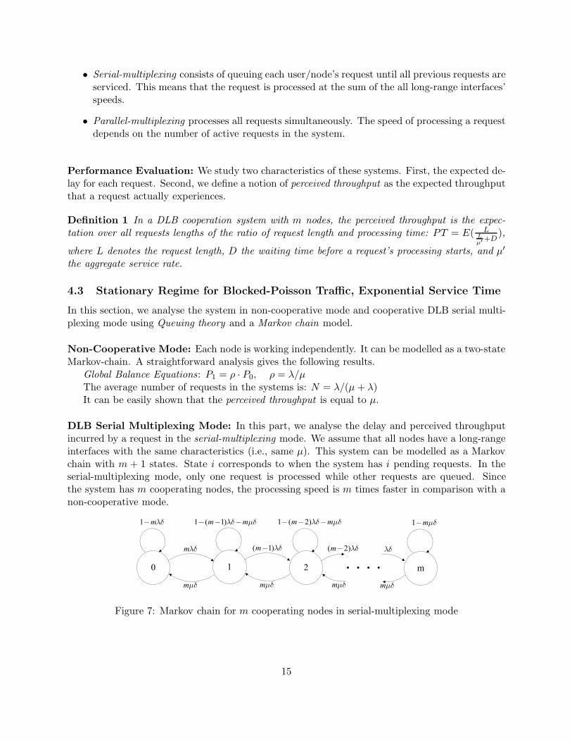
DLB Serial Multiplexing Mode: In this part, we analyse the delay and perceived throughputincurred by a request in the serial-multiplexing mode. We assume that all nodes have a long-rangeinterfaces with the same characteristics (i.e., same µ). This system can be modelled as a Markovchain with m + 1 states. State i corresponds to when the system has i pending requests. In theserial-multiplexing mode, only one request is processed while other requests are queued. Sincethe system has m cooperating nodes, the processing speed is m times faster in comparison with anon-cooperative mode.
0
1 m
m
m
1 ( 1)m m
( 1)m
m
1 ( 2)m m
( 2)m
m
1 2
m
1 m
m
Figure 7: Markov chain for m cooperating nodes in serial-multiplexing mode
15

Let Pi denote the stationary probability of being in state i. We have
Pi = [(m − i − 1)! (m
ρ)i ·
m∑
j=0
ρj
(m − j − 1)!mj]−1
Average number of requests in the system: N =∑m
i=0 i · Pi
Let Nk denote the number of requests in the system at time kδ (including the one beingprocessed). To compute the average delay, consider a newly arrived request. We first computethe current system state probability: P (Nt = i|Nt '= m), 0 ≤ i < m. This corresponds to theprobability that i requests are already in the system. The number of queued requests cannot be mor larger, because users are blocked after each request, and therefore, if there are already m queuedrequests no new request would arise.
P (Nt = i|Nt '= m) =P (Nt = i,Nt '= m)
P (Nt '= m)=
Pi
1 − Pm
For each P (Nt = i|Nt '= m) the delay is X1 + · · ·+Xi +X, where Xi denotes the time to process(transmit) existing request i and X is the time to process the new request. The average time forprocessing each of these requests is i+1
mµ . This holds true even for the request being processedbecause of the memoryless characteristic of the exponential distribution. Note that we cannotcompute the average delay using Little’s Theorem in a straightforward way. This is because theeffective arrival rate of the system is unknown but less than λ, which is due to the blocking natureof our request generation process. Combining all the cases, we obtain the following average delayfor finishing a transmission request:
T =m−1∑
i=0
(X1 + · · · + Xi + X) · P (Nt = i|Nt '= m)
T =m−1∑
i=0
(i + 1mµ
) · Pi
1 − Pm
Using the same approach the perceived throughput is as the following.
PT =∞∫
0
1µ
e−Lµ
m−1∑
i=0
L
(L+imµ )
· Pi
1 − PmdL
Our simulation of the Blocked-Poisson traffic with exponential service time and serial-multiplexingshows an exact match of the above analytical results (Figures 8 and 9). These results will be dis-cussed the next section.
4.4 Traffic Pattern
Serial vs. Parallel-Multiplexing for Blocked-Poisson Traffic: Depending on the type ofapplication, the parallel-multiplexing might be closer to the reality in comparison with serial-multiplexing. However, the analysis of the parallel-multiplexing is more complex and difficult to
16

reach a closed form formula. We simulated both multiplexing schemes using Matlab. In this section,we present the simulation results of both of the schemes in terms of delay and perceived throughput.We normalized the average service time per request to 1 unit of time (i.e., µ = 1). We varied thearrival rate for each node between µ
103 and 103µ. Note that we can use arrival rates higher than theservice time because our arrival process is Blocked-Poisson (the length of the queue never exceedsm). For each plotted point, we run the simulation for 500,000 unit of time. As reported in Figures 8and 9 both schemes show that at low and moderate load, DLB provides a significant reduction indelay and increase of perceived throughput.
10−3 10−2 10−1 100 101 102 1030.1
0.2
0.3
0.4
0.5
0.6
0.7
0.8
0.9
1
1.1
Load (!/µ), µ=1
Aver
age
dela
y
SerialParallel m=4
m=2
m=1
m=3
m=5
Figure 8: Average delay per packet for serial and parallel-multiplexing with Blocked-Poisson traffic.
The simulation indicates that the serial-multiplexing slightly outperforms the parallel-multiplexing.However, we note that Serial-multiplexing, exhibits a higher variance of delay (jitter).
10−3 10−2 10−1 100 101 102 1030.5
1
1.5
2
2.5
3
3.5
4
4.5
5
5.5
Load (!/µ) , µ=1
Perc
eive
d Th
roug
hput
SerialParallel m=5
m=4
m=3
m=2
m=1
Figure 9: Perceived Throughput as a func-tion of load for Blocked-Poisson traffic andm = 1, · · · , 5.
10−3 10−2 10−1 100 101 102 1030.75
0.8
0.85
0.9
0.95
1
1.05
Load (!/µ) , µ=1
Paar
alle
l to
Seria
l Thr
ough
put R
atio
m=1m=2m=3m=4m=5
Figure 10: Ratio of perceived throughputof parallel to serial-multiplexing for Blocked-Poisson traffic.
Heavy-Tail Traffic: The distribution of the size of web pages is commonly modelled as more of aheavy-tail than exponential distribution [31]. Because the analysis of the cooperative mode is much
17

harder for this type of traffic, we resort to simulations to quantify the performance improvementresulting from cooperation. The most popular and straightforward distributions for simulatingheavy-tail traffic is the Pareto distribution [32, 33].
Figure 11 indicates that under heavy-tail traffic, significant increase of the perceived throughputcan be achieved when the load is low or moderate. This time the serial-multiplexing substantiallyoutperforms the parallel-multiplexing. Parallel-multiplexing results in up to 45% lower perceivedthroughput than serial-multiplexing (compared to a 15% in exponential traffic, see Figure 10). Wewill try to explore this difference in the future research.
10−3 10−2 10−1 100 101 102 1030.5
1
1.5
2
2.5
3
3.5
4
4.5
5
5.5
Load (!/ Average Request Length), Average request Length=1
Perc
eive
d th
roug
hput
SerialParallel
m=4
m=2
m=1
m=3
m=5
Figure 11: Perceived throughput as a functionof load for heavy-tail traffic and m = 1, · · · , 5.
10−3 10−2 10−1 100 101 102 1030.4
0.5
0.6
0.7
0.8
0.9
1
Load (!/ Average Request Length), Average Request Length=1Pa
ralle
l to
seria
l Thr
ough
put R
atio
(Hea
vy−T
ail)
m=1m=2m=3m=4m=5
Figure 12: Ratio of perceived throughput ofparallel to serial-multiplexing for heavy-tailtraffic.
10−3 10−2 10−1 100 101 102 1030.5
1
1.5
2
2.5
3
3.5
4
4.5
5
5.5
Load (!/ Average Request Length), Average Request Length=1
Perc
eive
d th
roug
hput
(Ser
ial S
chem
e)
Heavy−Tail TrafficPoisson Traffic
m=4
m=2
m=1
m=3
m=5
Figure 13: Comparison of perceived through-put under exponential and heavy-tail trafficfor serial-multiplexing. Both traffics have thesame average request length.
10−3 10−2 10−1 100 101 102 103
1
1.2
1.4
1.6
1.8
2
Load (!/ Average Request Length), Average Request Length=1
Hea
vy−T
ail t
o Po
isso
n Th
roug
hput
Rat
io
m=1m=2m=3m=4m=5
Figure 14: Ratio of perceived throughput forheavy-tail traffic to exponential using serial-multiplexing. For the same average requestlength, heavy-tail traffic results in substan-tially better throughput.
We also compared the performance of DLB under heavy-tail and exponential traffic. Figures 13and 14 show the performance of DLB under both traffic for the same average request length using
18
serial-multiplexing. For moderate load, heavy-tail traffic results in a perceived throughput up to80% better than exponential traffic.
4.5 Prototype and Experimentation for Distributed Link Bonding Cooperation
Implementing DLB on the current Internet requires several modifications to the existing protocols.In the following, we discuss some of the possible solutions to integrate DLB within the currentInternet.
• DLB-Aware Applications: DLB can be implemented at the application layer. Whenever, anode initiates a communication with an application server, it also provides a list of cooperatingnodes for forwarding the data. This solution requires modifications to the application. Notethat many P2P applications, e.g., BitTorrent, are based on this principle.
• Multihomed Transport Protocols: DLB can be also abstracted from the application layerto the transport layer. That would result in a distributed multihomed Transport Protocol.The existing IETF Stream Control Transmission Protocol (SCTP) [34] would not be sufficient,as it provides limited support of simultaneous transmission through multiple paths. Thedrawback of such solution is that it requires the Internet servers to run the same modifiedtransport protocol.
• DLB-Aware Network Layer: Small modifications can be made to the network layer tosupport DLB. For example, if loose source routing is enabled, the mobile nodes can sourceroute their packets through the cooperating nodes. Some limitations with this approach arethe source routing is, in general, disabled to avoid various attacks, and it also implies makingmodification to the server protocol stack to allow the back flow traffic through the cooperatingnodes.
• Proxy-Based DLB: This approach consists of making modifications to the mobile nodes’protocol stack to first relay all the packets through the cooperating nodes to a proxy. Theproxy then acts as a Remote NAT and forwards the packets to the final destination. All trafficis sent back to the proxy which applies another address translation and relays the packetsthrough the cooperating nodes. A potential issue with this method is that the proxy becomesa bottleneck. But the advantage of this solution is that no modification is necessary in theapplications or outside the Internet. Our prototype adopts this proxy approach.
PrototypeThe system consists of two parts: the mobile stations and the DLB proxy. Figure 15 shows
the prototype configuration of the DLB system. For the ease of prototyping, we use laptops withcellular HSDPA and 1xEvDO PC cards to be the mobile stations, and later we will port the systemto the pocket-size mobile devices. The DLB system is based on the Click Modular Router [35, 36]and runs in Linux with kernel 2.6. In the DLB system, besides the WiFi wireless interface and thecellular wireless interface, we create a virtual network interface bound with a virtual IP address. Soour system can capture and process all the packets going through the virtual interface. As a result,no modification to the application is necessary except setting the application to use the virtualnetwork interface and IP address.
As many Virtual Private Network (VPN) implementations, the DLB system uses an IP overUDP encapsulation technique which means that each IP packet given to the virtual interface will
19

Local Network
Wi-Fi
Cellular Link
166.24.1.32
166.24.1.15
70.5.68.5
Cellular Operator A
Cellular Operator B
MS3
MS1
MS2
Wired Link
Web Server
DLB Proxy
Virtual IP:10.0.0.12
Virtual IP:10.0.0.13
Virtual IP:10.0.0.11
Cooperation Group Table
Internet
10.0.0.11 70.5.68.510.0.0.12 166.24.1.3210.0.0.13 166.24.1.15
Virtual Link
Figure 15: The prototype configuration of the DLB platform.
be wrapped within a UDP packet and sent to the DLB proxy. On the other end, when the UDPpacket arrives at the DLB proxy, the proxy strips the UDP header off the original UDP packet.
One of the reasons to choose IP over UDP is that firewalls are placed between mobile nodesand the internet by the cellular operators for security purposes. So we cannot use the techniqueslike IP over IP or Network address translation (NAT) directly because the modified IP packets willbe dropped by the firewall. Our experimentation result shows that the UDP packet encapsulationis fast and has low overhead.
After stripping-off the UDP header, the proxy does a network address translation (NAT) tomodify the virtual IP address to the public IP address. Finally the packet is transmitted throughthe wired network and delivered to the destination. The reverse process from the destination backto the mobile node is quite similar to the forward process. On receiving an IP packet from thedestination, the proxy performs a reverse NAT, encapsulate it in a UDP packet and relays it back toone of the cooperating nodes. On the UDP packet arriving at the mobile node, the UDP header willbe removed to extract the encapsulated IP packet, and pass it to TCP/IP stack for the application.
In order to improve the throughput of the system, the DLB system separates the traffic to mul-tiple links for both uploading and downloading. In the current prototype system, we implementedthe static packet scheduling which diverts the traffic to different links according to their capacities.This can be improved by using a dynamic load balancing technique, which is part of our futurework.
Experimentation ResultsThe initial measurements we made aimed at determining the overhead cost and providing a
proof of concept for distributed link-bonding. We developed and run a UDP speed test programthat sends packets at a constant rate higher than acceptable by each of the cellular PC cards butstill acceptable by the Internet. We use a 500KB/s data rate with UDP packet size of 1KB. We runthe program in three scenarios. Separately on each card without cooperation, and also using ourDLB implementation. Table 1 summarizes our measurements. The measurements indicate thatDLB results in very little overhead.
As a reliable transmission protocol, TCP is commonly used by many applications, such as webbrowsers. However, in our experiments, we found the TCP on DLB does not consistently deliverbetter results. This is mainly because the reordered packets damages the overall system throughput.
20

HSDPA 1xEvDO Bonding
9 am 115.1 151.8 254.712 pm 111.3 156.2 255.84 am 116.9 171.3 268.58 pm 116.8 167.1 277.3
Table 1: UDP download speed tests for separate channels and DLB.
Besides, the long range links of cooperating nodes are having different rates due to the technologies,services, and channel conditions. To optimize the performance, the rate allocation also need to beaddressed. Those will also be discussed in Section 4.6.
4.6 Transport Layer Optimization
The proposed DLB system can be further improved to provide efficient and reliable communications.Two major issues need to be addressed: rate allocation and packets reordering. These are still openproblems in the DLB system, that we propose to investigate as part of our future work.
Rate allocation is important to the DLB system where long-range links with multiple rates arebundled together, because it decides how the packets from multiple traffic sources are scheduled androuted. To schedule traffic, the proposed DLB system needs to adopt a fast and effective methodto estimate the bandwidth of each transmission link, because the cooperating nodes are mobile andthe rates express transient characteristics. Given a set of links with various characteristics, therate allocating algorithm should be able to decide the best possible rate for each link and for eachsession. As part of future work, we will investigate and evaluate various link estimation and rateallocating strategies.
The performance of current TCP running on DLB can be significantly reduced due to out-of-order packets caused by different rates and delays of bundled links. In TCP, the out-of-orderpackets would incur duplicate acknowledgements (DUPACKs) from the receiver. But the sender,which receives those DUPACKs, cannot differentiate if it is due to out-of-order delivery or packetloss. The current TCP design is under the assumption that the packet loss due to transmission lossis small and that packet reordering is rare. So TCP misinterprets out-of-order packet delivery as apacket loss due to congestion. However, our experiments demonstrate that packet reordering is verycommon in the DLB system. Several solutions such as RR-TCP, TCP-DOOR, TCP-PR [37, 38, 39]have been proposed, but they consider the case of only a single congestion path, which does notcorrespond to the considered DLB scenario where each link has independent transmission path.So the solution we propose builds on separate congestion windows for each cooperative link. Webelieve that this strategy has the potential to mitigate the issue of packet reordering.
5 Future Work and Timeline
To complete this thesis research, we propose the following future work and timeline (Table 2).
• Analysis of Post Soft-Demodulation combining and Decode-and-Forward com-bining. The proposed PMRC technique gives the best error correction performance, but itrequires significant amount of bandwidth and computation. In an environment with moder-ate fading and noise, this strategy becomes too expensive to execute. In our framework, we
21

suggested an adaptive strategy - HPC with lightweight channel combining algorithms suchas Post Soft-Demodulation and Decode and Forward. Intuitively, the error correction abilityis sub-optimal in the lightweight algorithms. I plan to quantify the error resilience underlimited local network bandwidth, and compare it with the performance of PMRC. I will usethe same metrics used in PMRC including the outage probability, bit error rate, throughput,and local bandwidth requirement.
• Experimental evaluation of Post Soft-Demodulation combining. To evaluate PostSoft-Demodulation combining in real world experiments, we are currently building a testingplatform. The testbed is implemented on GNU Radio and the Universal Software RadioPeripheral (USRP). We believe that the Post Soft-Demodulation combining is promising onboth error-correction performance and local bandwidth consumption. As part of this research,the experiments includes finding the proper quantization value, bit error rate, and throughputfor different noise levels, attenuation, and fading.
• Rate allocation and bandwidth estimate for multi-rate channels. When adopting acooperative traffic multiplexing strategy, nodes with different rates are relaying traffic for eachother. The rate allocating and packet scheduling is the key to the overall system performance.My future study is to first develop an efficient method of estimating the link quality andbandwidth of each transmission path. Then I will study the rate allocation mechanisms. Thispart of the research includes developing, prototyping and evaluating a strategy for allocatingrates over a set of links with various characteristics.
• Optimization of packet reordering for DLB. Multiplexing multiple channels with variousrates and delays would result in a largely downgraded performance of the existing TCP dueto the packet reordering issue. My future research aims at solving the performance issueof TCP on DLB with a minimal impact on the existing infrastructure. Proxy mode is themost promising candidate so far. In this mode, the master node distributes the packets toall assisting nodes, and a proxy is involved to collect all those packets and relay them to thedestination, and similarly for the reverse flow of traffic. The study includes mechanisms forthe management of multiple congestion windows and DUACKs filtering.
Activities Exp. DateAnalysis of Decode and Forward combining January 2010Analysis of Post Soft-Demodulation combining January 2010Experimental evaluation of Post Soft-Demodulation combining February 2010Rate allocation and bandwidth estimate for multi-rate channels March 2010Optimization of packet reordering for DLB May 2010Dissertation Defense June 2010
Table 2: Timeline for the next level activities and expected due date.
References
[1] M. Rumney, “Identifying technology to deliver the next 100x capacity growth in wireless,” The3rd LTE World Summit, 2008.
22

[2] iPhone vs. Pre: Satisfaction bakeoff. http://brainstormtech.blogs.fortune.cnn.com/2009/08/14/iphone-vs-pre-satisfaction-bakeoff/.
[3] Customers Angered as iPhones Overload AT&T. http://www.nytimes.com/2009/09/03/technology/companie
[4] Mobile broadband still crawling at below 1Mb, despite ’up to’ 7.2Mb claims.http://mobile.broadbandgenie.co.uk/broadband-news/mobile-broadband-still-crawling-at-below-1mb-despite-up-to-7mb-claims.
[5] Apple Genius Bar: iPhones’ 30% Call Drop Is ”Normal” in New York.http://gizmodo.com/5370493/apple-genius-bar-iphones-30-call-drop-is-normal-in-new-york.
[6] Apple Genius says 30 percent iPhone call drop rate is average in New York.http://www.engadget.com/2009/09/30/apple-genius-says-30-iphone-call-drop-rate-is-average-in-new-yo/.
[7] J. Proakis, Digital Communications 4 edition. McGraw-Hill, 2000.
[8] T. S. Rappaport, Wireless Communications: Principles and Practice 2 edition. Prentice HallPTR.
[9] A. Goldsmith, Wireless Communications. Cambridge University Press, 2005.
[10] D. Tse and P. Viswanath, Fundamentals of Wireless Communication. Cambridge UniversityPress, 2005.
[11] A. Sendonaris, E. Erkip, and B. Aazhang, “User cooperation diversity– part i and part ii,”IEEE Transactions on Communications, vol. 51, no. 11, pp. 1927–1948, 2003.
[12] D. G. Brennan, “Linear diversity combining techniques,” Proceedings of the IEEE, vol. 91,no. 2, 2003.
[13] F. H. P. Fitzek and M. D. Katz, Cooperation in Wireless Networks: Principles and Appli-cations: Real Egoistic Behavior is to Cooperate! Secaucus, NJ, USA: Springer-Verlag NewYork, Inc., 2006.
[14] J. N. Laneman and G. W. Wornell, “Energy-efficient antenna sharing and relaying for wirelessnetworks,” Proc. IEEE Wireless Communications and Networking Conference (WCNC), Sep.2000.
[15] ——, “Exploiting distributed spatial diversity in wireless networks,” Proc. Allerton Conf.Communications, Control, and Computing, 2000.
[16] J. N. Laneman, D. N. Tse, and G. W. Wornell, “Cooperative diversity in wireless networks:Efficient protocols and outage behavior,” IEEE Trans. on Info. Theory, vol. 50, no. 12, 2004.
[17] T. E. Hunter and A. Nosratinia, “Cooperation diversity through coding,” Proc. IEEE ISIT,p. 220, 2002.
[18] ——, “Diversity through coded cooperation,” IEEE Trans. on Wireless Commun., vol. 5, no. 2,2006.
23
[19] J. Adeane, M. R. D. Rodrigues, and I. J. Wassell, “Characterisation of the performance ofcooperative networks in ricean fading channels,” 12th International Conference on Telecom-munications, 2005.
[20] A. Khandani, E. Modiano, J. Abounadi, and L. Zheng, “Reliability and route diversity inwireless networks,” Conference on Information Science and System, 2005.
[21] ——, “Cooperative routing in wireless networks,” Allerton Conference on Communications,Control and Computing, 2003.
[22] R. Ramanathan, “Challenges: A radically new architecture for next generation mobile ad hocnetworks,” Proceedings of ACM Mobicom, 2005.
[23] G. Jakllari, S. Krishnamurthy, M. Faloutsos, P. V. Krishnamurthy, and O. Ercetin, “A frame-work for distributed spatio-temporal communications in mobile ad hoc networks,” IEEE IN-FOCOM, 2006.
[24] M. Tope, J.C.McEachen, and A. Kinney, “Ad-hoc network routing using co-operative diver-sity,” In Proceedings of the 20th International Conference on Advanced Information Networkingand Applications, 2006.
[25] A. zgr, O. Lvque, and D. Tse, “Hierarchical Cooperation Achieves Optimal Capacity Scalingin Ad Hoc Networks,” IEEE Transactions on Information Theory, 2007.
[26] zgr Oyman and A. J. Paulraj, “Leverages of distributed mimo relaying: A shannon-theoreticperspective,” Proc. 1st IEEE Workshop on Wireless Mesh Networks, year = 2005,.
[27] P. Bahl, A. Adya, J. Padhye, and A. Walman, “Reconsidering wireless systems with multipleradios,” SIGCOMM Comput. Commun. Rev., vol. 34, no. 5, pp. 39–46, 2004.
[28] H. Luo, R. Ramjee, P. Sinha, L. E. Li, and S. Lu, “Ucan: a unified cellular and ad-hoc networkarchitecture,” MobiCom ’03: Proceedings of the 9th annual international conference on Mobilecomputing and networking, 2003.
[29] S. G. Sachin Katti and D. Katabi, “Embracing wireless interference: Analog network coding,”SIGCOMM, 2007.
[30] H. B. Kyle Jamieson, “Partial packet recovery for wireless networks,” SIGCOMM, 2007.
[31] M. E. Crovella and A. Bestavros, “Self-similarity in World Wide Web traffic: evidence andpossible causes,” vol. 5, no. 6, 1997, pp. 835–846.
[32] T. D. Neame, M. Zukerman, and R. Addie, “A practical approach for multimedia trafficmodeling,” in Broadband Communications, 1999, pp. 73–82.
[33] M. Zukerman, T. Neame, and R. Addie, “Internet traffic modeling and future technologyimplications,” 2003.
[34] R. Stewart, Q. Xie, K. Morneault, C. Sharp, H. Schwarzbauer, T. Taylor, I. Rytina, M. Kalla,L. Zhang, and V. Paxson, “Stream control transmission protocol,” IETF RFC 2960, 2000.
24

[35] The Click Modular Router. http://www.read.cs.ucla.edu/click/.
[36] E. Kohler, R. Morris, B. Chen, J. Jannotti, and M. F. Kaashoek, “The click modular router.”ACM Transactions on Computer Systems, vol. 18, no. 3, 2000.
[37] M. Zhang, B. Karp, S. Floyd, and L. Peterson, “Rr-tcp: A reordering-robust tcp with dsack,”Network Protocols, IEEE International Conference on, 2003.
[38] F. Wang and Y. Zhang, “Improving tcp performance over mobile ad-hoc networks with out-of-order detection and response,” MobiHoc, 2002.
[39] L. J. C. S. Bohacek, J.P. Hespanha and K. Obraczka, “A new tcp for persistent packet re-ordering,” Networking, IEEE/ACM Transactions on, vol. 14, 2006.
25