photo-injector laser for ctf3 and clic -...
TRANSCRIPT

Photo-injector laser for CTF3 and CLIC
Marta Csatari DivallCERN/EN/STI/LP
CAS Erice9th April 2011
Outline
CAS, Erice, 9th April 2011
• CLIC project
• Photo-injectors
• Choice of drive beam
• The laser system
• Time structure/Phase-coding
• The electron beam
• Photo-injector for CLIC/ challenges
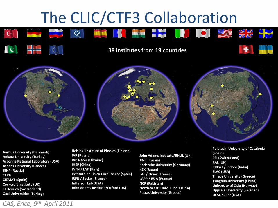
The CLIC/CTF3 Collaboration
38 institutes from 19 countries
Helsinki Institute of Physics (Finland)IAP (Russia)IAP NASU (Ukraine)IHEP (China)INFN / LNF (Italy)Instituto de Fisica Corpuscular (Spain)IRFU / Saclay (France)Jefferson Lab (USA)John Adams Institute/Oxford (UK)
Polytech. University of Catalonia (Spain)PSI (Switzerland)RAL (UK)RRCAT / Indore (India)SLAC (USA)Thrace University (Greece)Tsinghua University (China)University of Oslo (Norway)Uppsala University (Sweden)UCSC SCIPP (USA)
Aarhus University (Denmark)Ankara University (Turkey)Argonne National Laboratory (USA)Athens University (Greece)BINP (Russia)CERNCIEMAT (Spain)Cockcroft Institute (UK)ETHZurich (Switzerland)Gazi Universities (Turkey)
John Adams Institute/RHUL (UK)JINR (Russia)Karlsruhe University (Germany)KEK (Japan) LAL / Orsay (France) LAPP / ESIA (France)NCP (Pakistan)North-West. Univ. Illinois (USA)Patras University (Greece)
CAS, Erice, 9th April 2011
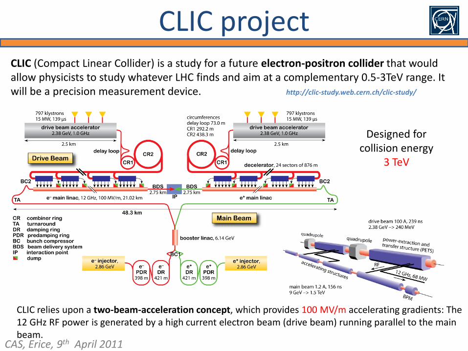
CLIC project CLIC (Compact Linear Collider) is a study for a future electron-positron collider that would allow physicists to study whatever LHC finds and aim at a complementary 0.5-3TeV range. It will be a precision measurement device.
CLIC relies upon a two-beam-acceleration concept, which provides 100 MV/m accelerating gradients: The 12 GHz RF power is generated by a high current electron beam (drive beam) running parallel to the main beam.
http://clic-study.web.cern.ch/clic-study/
Designed for collision energy
3 TeV
CAS, Erice, 9th April 2011
coils
cathode
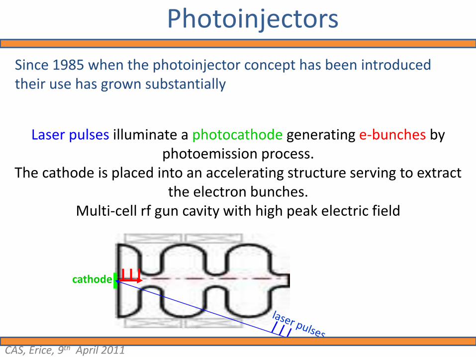
Since 1985 when the photoinjector concept has been introduced their use has grown substantially
Laser pulses illuminate a photocathode generating e-bunches by photoemission process.
The cathode is placed into an accelerating structure serving to extract the electron bunches.
Multi-cell rf gun cavity with high peak electric field
Photoinjectors
CAS, Erice, 9th April 2011
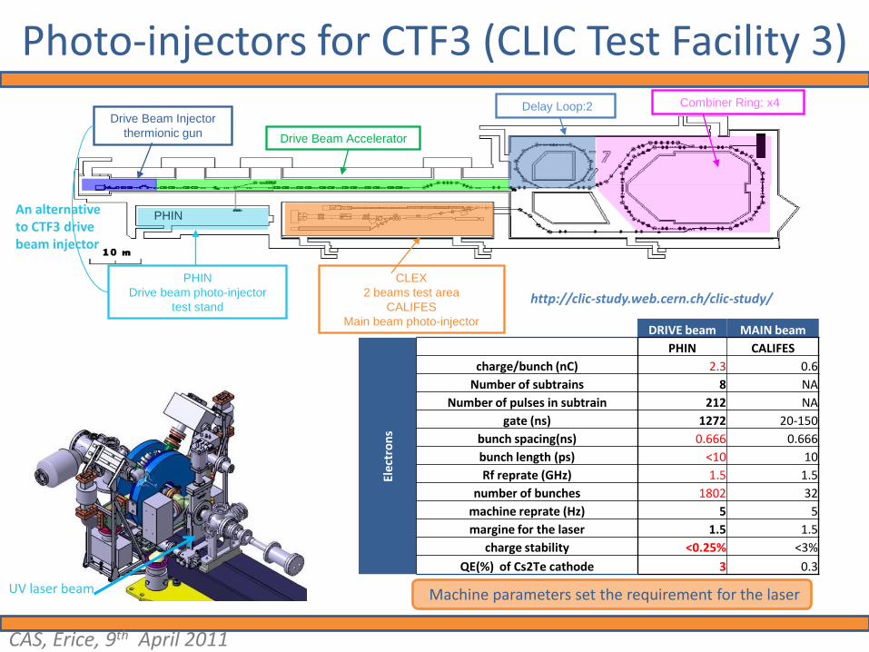
Photo-injectors for CTF3 (CLIC Test Facility 3)
D FFD
DF
F
D F D
D F D
F
FD
D F D
D F D
DF DF DF DF DF DF DF DF DF
D F D
F DF D
D FFFDD
DF
FDD
FF
FF
D F DD F D
D F DD F D
F
FD
F
FD
F
FD
D F DD F D
D F DD F D
DF DF DF DF DF DF DF DF DF DFDF DF DF DF DF DF DF DF DF DF DF DF DF DF DF DF
D F DD F D
F DF DF DF D
Drive Beam Accelerator
Delay Loop:2 Combiner Ring: x4
CLEX
2 beams test area
CALIFES
Main beam photo-injector
Drive Beam Injector
thermionic gun
PHIN
PHIN
Drive beam photo-injector
test stand
UV laser beam
DRIVE beam MAIN beam
Ele
ctro
ns
PHIN CALIFES
charge/bunch (nC) 2.3 0.6
Number of subtrains 8 NA
Number of pulses in subtrain 212 NA
gate (ns) 1272 20-150
bunch spacing(ns) 0.666 0.666
bunch length (ps) <10 10
Rf reprate (GHz) 1.5 1.5
number of bunches 1802 32
machine reprate (Hz) 5 5
margine for the laser 1.5 1.5
charge stability <0.25% <3%
QE(%) of Cs2Te cathode 3 0.3
An alternative to CTF3 drive beam injector
Machine parameters set the requirement for the laser
http://clic-study.web.cern.ch/clic-study/
CAS, Erice, 9th April 2011
Drive Beam injector choiceBaseline: Thermionic gun with 500 MHz sub harmonic bunching and bunch
compressor, 1 GHz acceleration
Advantages of a photo injector for the CLIC DB
• Time structure already defined by the laser, short bunches
• Satellite-free phase coding, less losses
• No bunching system needed and less bunch compression later on
• Smaller emittance < 10 m in theory, < 40 m from PHIN extrapolation
(thermionic gun is specified for < 100 m )
Disadvantages:
• Potential ‘frequent’ cathode changes (5 days)
•Amplitude stability of the laser transferred to charge instabilities
CAS, Erice, 9th April 2011

The time structure/beam combination
CAS, Erice, 9th April 2011
A. Aderrson
Delay Loop
Combiner Ring12 GHz
3 GHz
q 1.5 GHz
After every 212 bunches 180 phase-shift is necessary
1.5GHz RF deflectors
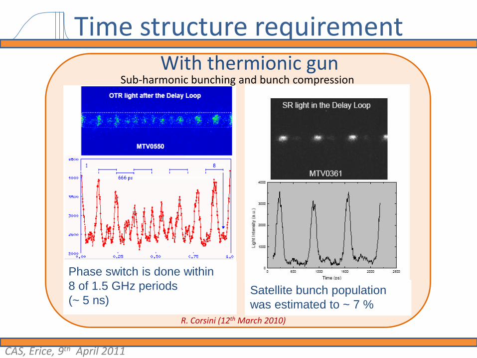
Time structure requirement
Phase switch is done within
8 of 1.5 GHz periods
(~ 5 ns)Satellite bunch population
was estimated to ~ 7 %
R. Corsini (12th March 2010)
With thermionic gunSub-harmonic bunching and bunch compression
CAS, Erice, 9th April 2011

Laser setup
1.5 GHzSynched oscillator
Cwpre-
amplifier
10W
Phase-coding
3-pass amplifier
2-pass amplifier
3.5kW 8.3kW 7.8kW14.8mJ in 1.2μs
2ω3.6kW
4.67mJ in 1.2μs4ω
1.25kW1.5mJ in 1.2μs
Feed-back stab.
Feed-back stab.
HighQ front end
Cooling
AMP1 head assembly
AMP1 and AMP2
Phase-coding test
Harmonics
Booster amplifier
Harmonics test stand
CAS, Erice, 9th April 2011
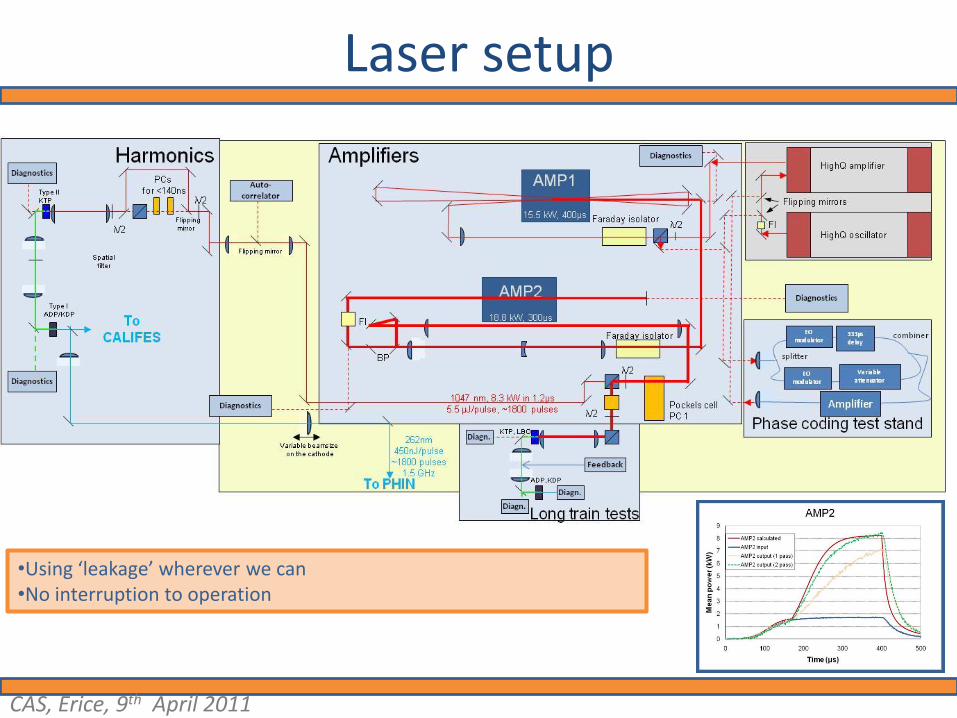
Laser setup
•Using ‘leakage’ wherever we can•No interruption to operation
CAS, Erice, 9th April 2011
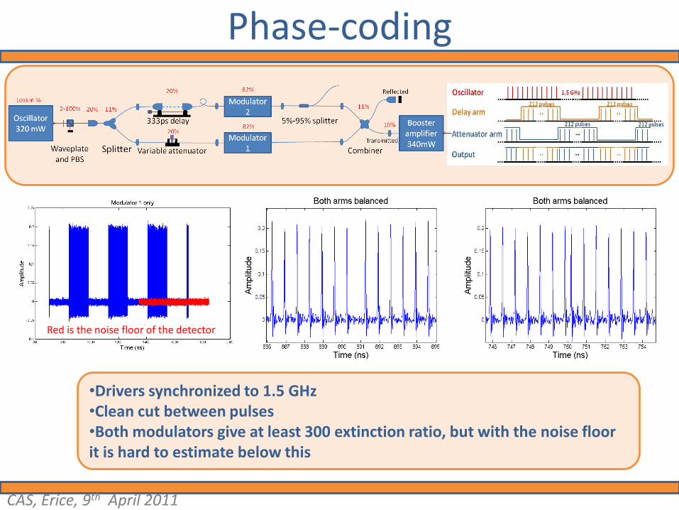
Phase-coding
Red is the noise floor of the detector
•Drivers synchronized to 1.5 GHz•Clean cut between pulses•Both modulators give at least 300 extinction ratio, but with the noise floor it is hard to estimate below this
CAS, Erice, 9th April 2011
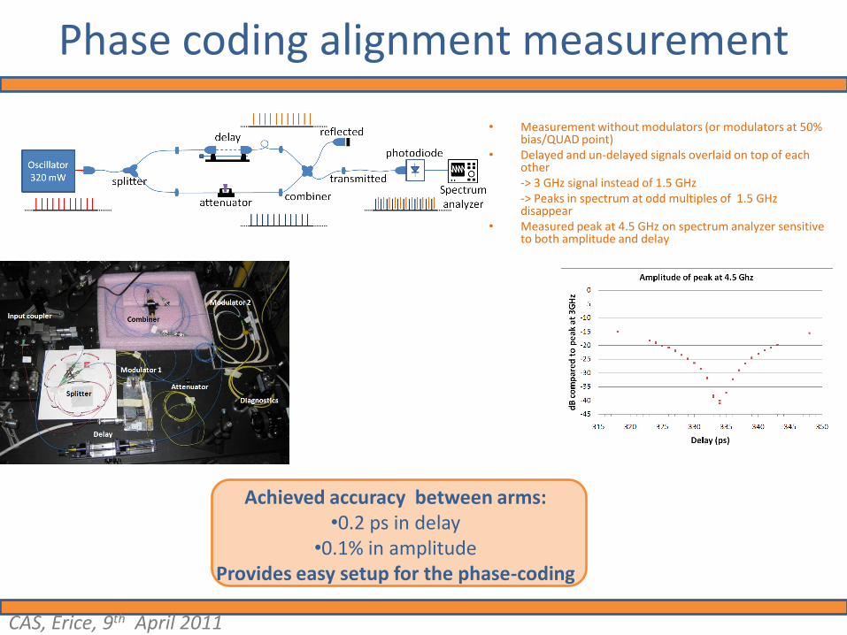
Phase coding alignment measurement
• Measurement without modulators (or modulators at 50% bias/QUAD point)
• Delayed and un-delayed signals overlaid on top of each other-> 3 GHz signal instead of 1.5 GHz-> Peaks in spectrum at odd multiples of 1.5 GHz disappear
• Measured peak at 4.5 GHz on spectrum analyzer sensitive to both amplitude and delay
Achieved accuracy between arms:•0.2 ps in delay
•0.1% in amplitudeProvides easy setup for the phase-coding
A. Drozdy tech. stud.
CAS, Erice, 9th April 2011
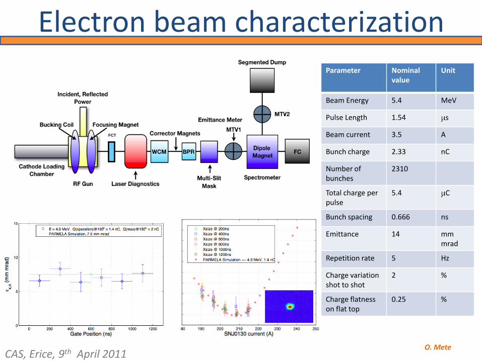
Electron beam characterization
14
FCT
Parameter Nominalvalue
Unit
Beam Energy 5.4 MeV
Pulse Length 1.54 s
Beam current 3.5 A
Bunch charge 2.33 nC
Number of bunches
2310
Total charge per pulse
5.4 C
Bunch spacing 0.666 ns
Emittance 14 mm mrad
Repetition rate 5 Hz
Charge variation shot to shot
2 %
Charge flatness on flat top
0.25 %
O. MeteCAS, Erice, 9th April 2011
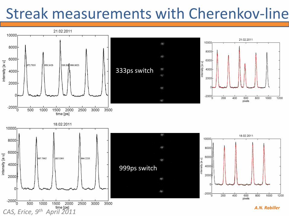
Streak measurements with Cherenkov-line
333ps switch
999ps switch
A.N. RabillerCAS, Erice, 9th April 2011
DRIVE beam MAIN beam
Ele
ctro
ns
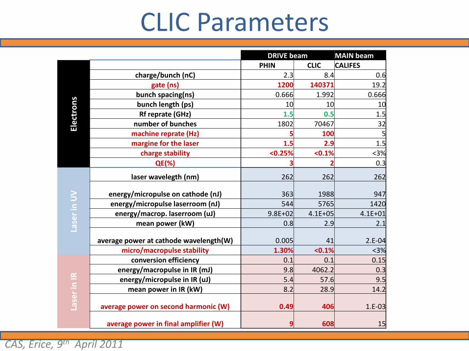
PHIN CLIC CALIFEScharge/bunch (nC) 2.3 8.4 0.6
gate (ns) 1200 140371 19.2bunch spacing(ns) 0.666 1.992 0.666bunch length (ps) 10 10 10Rf reprate (GHz) 1.5 0.5 1.5
number of bunches 1802 70467 32machine reprate (Hz) 5 100 5margine for the laser 1.5 2.9 1.5
charge stability <0.25% <0.1% <3%
QE(%) 3 2 0.3
Lase
r in
UV
laser wavelegth (nm) 262 262 262
energy/micropulse on cathode (nJ) 363 1988 947energy/micropulse laserroom (nJ) 544 5765 1420
energy/macrop. laserroom (uJ) 9.8E+02 4.1E+05 4.1E+01mean power (kW) 0.8 2.9 2.1
average power at cathode wavelength(W) 0.005 41 2.E-04micro/macropulse stability 1.30% <0.1% <3%
Lase
r in
IR
conversion efficiency 0.1 0.1 0.15energy/macropulse in IR (mJ) 9.8 4062.2 0.3energy/micropulse in IR (uJ) 5.4 57.6 9.5
mean power in IR (kW) 8.2 28.9 14.2
average power on second harmonic (W) 0.49 406 1.E-03
average power in final amplifier (W) 9 608 15
CLIC Parameters
CAS, Erice, 9th April 2011
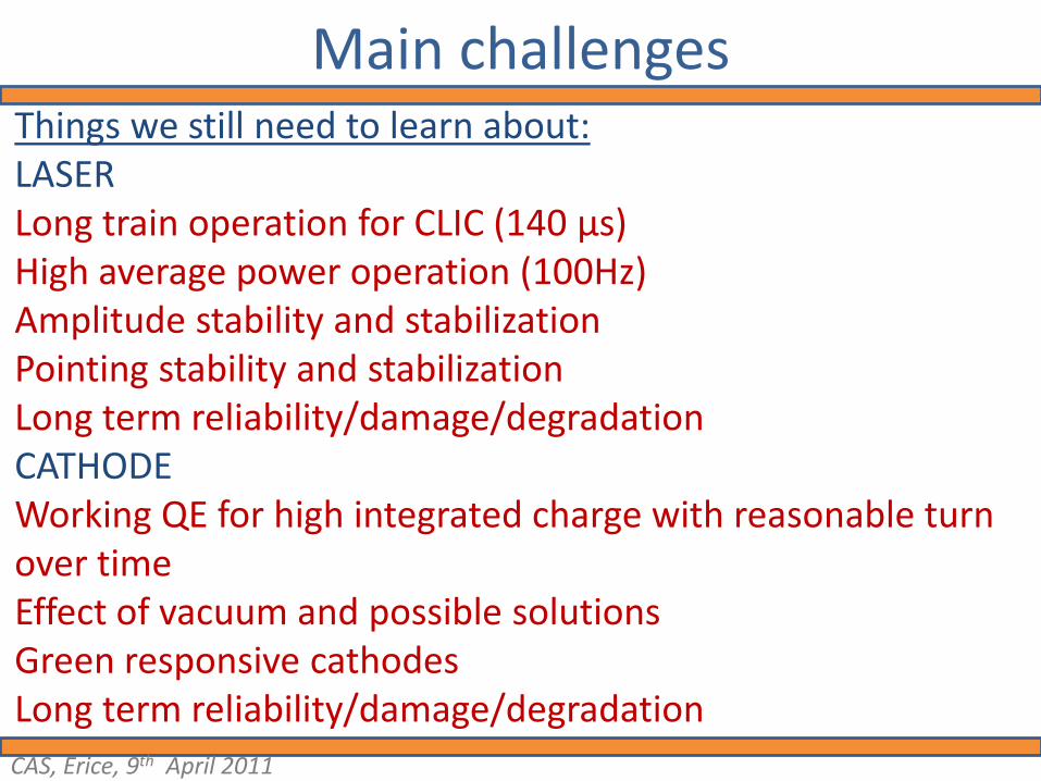
Main challengesThings we still need to learn about:LASERLong train operation for CLIC (140 μs)High average power operation (100Hz)Amplitude stability and stabilizationPointing stability and stabilization Long term reliability/damage/degradationCATHODEWorking QE for high integrated charge with reasonable turn over timeEffect of vacuum and possible solutionsGreen responsive cathodesLong term reliability/damage/degradation
CAS, Erice, 9th April 2011

BEAM DYNAMICS: S. Doebert, O. Mete
DIAGNOSTICS: B. Bolzon, E. Bravin, A. Dabrowski, D. Egger, T.
Lefevre, M. Olvegaard, A.N. Rabiller
LASER: V. Fedossev, C. Hessler, M. Martyanov, M. Petrarca
CATHODE: E. Chevallay, vacuum group
PHASE-CODING: A. Drozdy, S. Livesley, A. Andersson
CONTROLS and STABILIZATION: S. Batuca, M. Donze, A. Massi,
M.D'Arco, S. Gim
……. and many more
The team
CAS, Erice, 9th April 2011
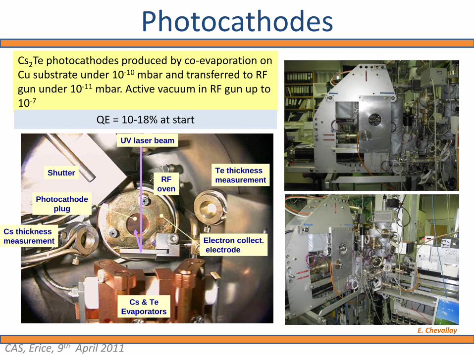
Photocathodes
UV laser beam
Shutter
Cs & Te
Evaporators
Cs thickness
measurement
Te thickness
measurement
Electron collect.
electrode
RF
oven
Photocathode
plug
UV laser beam
Shutter
Cs & Te
Evaporators
Cs thickness
measurement
Te thickness
measurement
Electron collect.
electrode
RF
oven
Photocathode
plug
Cs2Te photocathodes produced by co-evaporation on Cu substrate under 10-10 mbar and transferred to RF gun under 10-11 mbar. Active vacuum in RF gun up to 10-7
QE = 10-18% at start
E. Chevallay
CAS, Erice, 9th April 2011
IWLC2010 21st October Lasers for CTF3 and outlook for CLIC
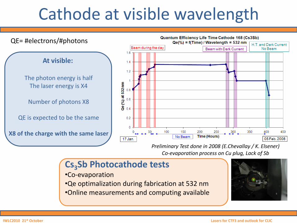
Cathode at visible wavelength
Preliminary Test done in 2008 (E.Chevallay / K. Elsener)Co-evaporation process on Cu plug, Lack of Sb
Cs3Sb Photocathode tests•Co-evaporation•Qe optimalization during fabrication at 532 nm•Online measurements and computing available
QE= #electrons/#photons
At visible:
The photon energy is halfThe laser energy is X4
Number of photons X8
QE is expected to be the same
X8 of the charge with the same laser
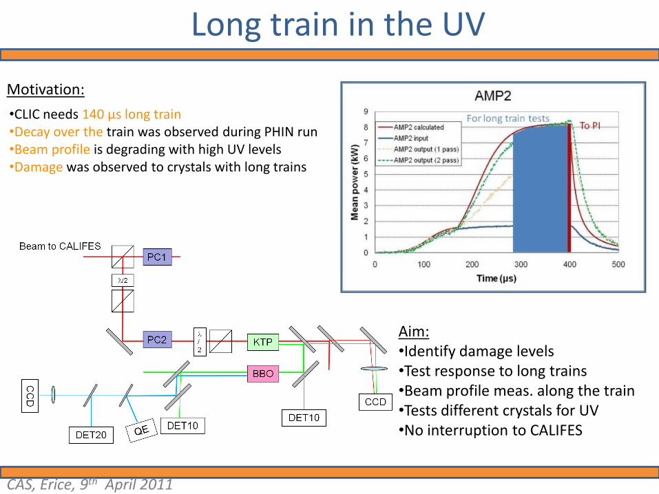
Long train in the UV
•CLIC needs 140 µs long train•Decay over the train was observed during PHIN run•Beam profile is degrading with high UV levels•Damage was observed to crystals with long trains
Motivation:
Aim:•Identify damage levels•Test response to long trains•Beam profile meas. along the train•Tests different crystals for UV•No interruption to CALIFES
CAS, Erice, 9th April 2011
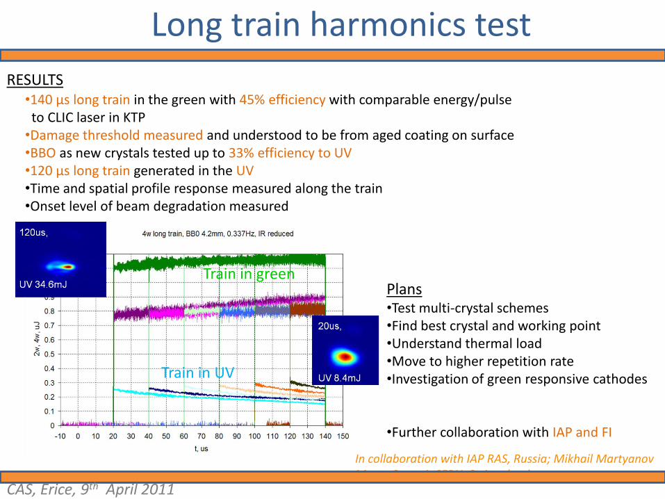
•140 µs long train in the green with 45% efficiency with comparable energy/pulse to CLIC laser in KTP
•Damage threshold measured and understood to be from aged coating on surface •BBO as new crystals tested up to 33% efficiency to UV•120 µs long train generated in the UV•Time and spatial profile response measured along the train•Onset level of beam degradation measured
RESULTS
Plans•Test multi-crystal schemes•Find best crystal and working point•Understand thermal load•Move to higher repetition rate•Investigation of green responsive cathodes
•Further collaboration with IAP and FI
In collaboration with IAP RAS, Russia; Mikhail MartyanovMarta Csatari, CERN, Switzerland
Train in green
Train in UV
Long train harmonics test
CAS, Erice, 9th April 2011

Scheme to improve stability
In TESLA this system was invented by I. Will and his group0.7% rms stability was achieved from 3% with 70% transmission
We need 0.1% rms stability
Stabilization constraints:• Pockels cell absorptive in UV (control in UV not
advisable)• Laser is in burst mode at all stages after preamp
with shorter burst length after Pockels-cell• Realtime response necessary
Stabilization options (WIP):• Feedback control loop at IR or GR using
~Conoptics noise eater. (Market survey needed)• Feedforward control before 4th harmonic using
measurements from earlier stages to determine level correction. (Further studies)
• Hybrid
LASS-II by ConopticsNoise reduction:1/1@ 500kHz5/1 @ 100kHz 18/1 @50kHz 100/1 @10kHz ,200/1 @1kHz250/1 @200hz
All options to be investigated in 2011 with tests on laser
CAS, Erice, 9th April 2011
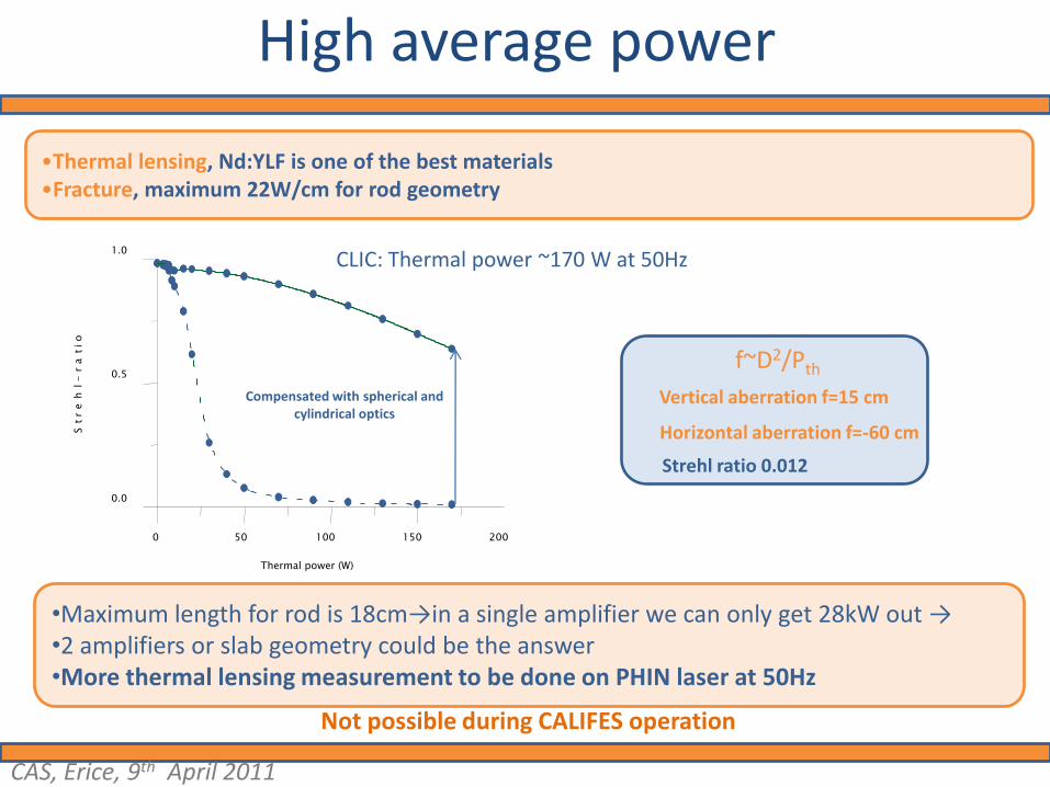
High average power
•Thermal lensing, Nd:YLF is one of the best materials •Fracture, maximum 22W/cm for rod geometry
CLIC: Thermal power ~170 W at 50Hz
Vertical aberration f=15 cm
Horizontal aberration f=-60 cm
Strehl ratio 0.012
f~D2/Pth
1.0
0 50 100 150 200
Thermal power (W)
0.0
0.5
St
re
hl-
ra
tio
Compensated with spherical and cylindrical optics
•Maximum length for rod is 18cm→in a single amplifier we can only get 28kW out →•2 amplifiers or slab geometry could be the answer•More thermal lensing measurement to be done on PHIN laser at 50Hz
Not possible during CALIFES operation
CAS, Erice, 9th April 2011