physical model of fluid flow characteristics in rh-top vacuum refining process
TRANSCRIPT

International Journal of Minerals, Metallurgy and Materials Volume 19, Number 6, June 2012, Page 483 DOI: 10.1007/s12613-012-0584-4
Corresponding author: Yan-ping Bao E-mail: [email protected] © University of Science and Technology Beijing and Springer-Verlag Berlin Heidelberg 2012
Physical model of fluid flow characteristics in RH-TOP vacuum refining process
Lu Lin1), Yan-ping Bao1), Feng Yue2), Li-qiang Zhang1), and Hong-lin Ou2)
1) State Key Laboratory of Advanced Metallurgy, University of Science and Technology Beijing, Beijing 100083, China 2) Engineering Research Institute, University of Science and Technology Beijing, Beijing 100083, China (Received: 25 June 2011; revised: 11 July 2011; accepted: 23 July 2011)
Abstract: To understand the characteristic of circulation flow rate in 250-t RH-TOP vacuum refining process, the l:4 water model test was established through the bubble behavior and gas holdup in the up-leg to investigate the effects of different processes and equipment parame-ters on the RH circulation flow rate. With the increases of lifting gas flow rate, lifting bubble travel, and the internal diameter of the up-leg, and the decrease of nozzle diameter, the work done by bubble floatage and the circulation flow rate increase. The expression of circulation flow rate was derived from the regression analysis of experiment data. Meanwhile, the influences of vacuum chamber pressure and nozzle blockage situation on the circulation flow rate were discussed in detail by the bubble behavior and gas holdup in the up-leg. It is necessary to maintain a certain vacuum chamber liquid level in the molten steel circulation flow. Compared with a nozzle with symmetrical blockage in the up-leg, when a nozzle with non-symmetrical blockage is applied, the lifting gas distribution is non-uniform, causing a great effect on the molten steel circulation flow and making the circulation flow drop largely.
Keywords: steelmaking; refining; molten steel; flow characteristic; bubbles; nozzles
Nomenclature:
B: Lifting height of liquid steel, m;
d0: Nozzle diameter, mm;
Du: Up-leg internal diameter, mm;
g: Acceleration of gravity, m·s−2;
hBub: Bubble travel, mm;
Hvac: Liquid level in the vacuum chamber, mm;
Himm: Snorkel immersion depth, mm;
Lp: Blowing gas penetration depth, mm;
M : Quality of lifting liquid steel, kg;
P: Vacuum chamber pressure, Pa;
P0: Atmospheric pressure, Pa;
QAr0: Lifting gas flow rate of the prototype, m3·h−1;
QCir: Circulation flow rate of the model, t·h−1;
QCir-p: Circulation flow rate of the prototype, t·h−1;
Qg : Lifting gas flow rate of the model, m3·h−1;
tmix: Mixing time, s;
ug0: Bubble initial velocity of the nozzle outlet, m·s−1;
Wgas: Gas expansion work, J;
Wloss: Lost work, J;
Wsteel: Required work for lifting liquid steel, J;
α: Gas holdup;
ρg: Gas density, kg·m−3;
ρl: Liquid density, kg·m−3;
ρg-l: Gas-liquid two-phase mixture density, kg·m−3;
1. Introduction
With the development of manufacturing industries, such as automobiles, electrical appliances and machinery, the demand of ultra low-carbon steel is growing; therefore, the RH vacuum refining process becomes one of the general methods to produce ultra low-carbon steel because of its fa-

484 Int. J. Miner. Metall. Mater., Vol.19, No.6, June 2012
vorable decarburization ability. The main functions (decar-bonization and degasification) of the RH refining process are achieved by the molten steel circulation flow, and the investigation on molten steel circulation flow characteristics in RH has positive effect on the technology optimization and actual production. The circulation flow rate is the im-portant index that reflects the RH circulation flow and re-fining efficiency. Many researchers studied the influence of molten steel circulation flow rate with different parameters to raise the RH refining process efficiency [1-4]. For exam-ple, Fan and Li et al. [5-6] used many snorkels to replace the traditional two snorkels; Kuwabara et al. [7] used oval snorkels to replace round snorkels to enhance the equivalent diameter. Because of the high temperature characteristic of metallurgy experiment, a physical model based on the simi-larity principle becomes a common method to study the RH refining process [2-8]. Moreover, there are very few reports about the overall evaluation and influence of nozzle internal diameter, lifting gas travel, and nozzle blockage [9] on the molten steel circulation flow.
Based on the summary of predecessor research, this arti-cle studied the effects of factors on the circulation flow rate through bubble behavior and gas holdup in the up-leg, such as input gas flow rate, snorkel diameter, bubble travel, and nozzle diameter. The regression formula of circulation flow rate with these factors was obtained, and the influences and reasons of vacuum chamber pressure and nozzle blockage situation on the circulation flow rate were discussed.
2. Experimental
2.1. Similarity of the model and the prototype
A water model of 1/4 linear scale for 250-t RH-TOP was established. Table 1 gives the main parameters of the proto-type and physical model based on the similarity principle. The actual lifting gas flow rate can be converted to the modified Froude criterion in the experiment. The relation-ship between model and actual standard gas flow rate is shown as Qg=0.0252QAr0 (1)
Table 1. Parameters of the water model and prototype
Ladle / mm Vacuum chamber / mm Snorkels / mm Main parameters Height Liquid level
Upper internal diameter
Lower internal diameter
Internal diameter Height Length Internal diameter
Prototype 4210 3780 3936 3615 2310 13350 1675 750.0 Model 1052 945 984 904 578 1000 419 130.0-187.5
2.2. Experimental devices and research methods
This experiment used a TDS-100H handhold ultrasonic wave flowmeter to measure the circulation flow rate in the precondition, so that the flow field was not destroyed. The liquid volume flow rate in the down-leg was selected as the circulation flow rate, and the ultrasonic wave flowmeter in-stalled on the down-leg can gather the circulation flow rate data dynamically [10]. The certain saturated potassium chloride solution was poured into the vacuum chamber, and the conductivity instrument was applied to measure the changes of water solution conductivity in the ladle to deter-mine the mixing time. The experimental device is shown in Fig. 1.
2.3. RH work principle and bubble behavior
The bubble entered into the up-leg with the initial veloc-ity through the nozzle, afterward the speed decreased gradu-ally. The bubble floated primarily and drove the molten steel rising. The bubble path is shows in Fig. 2, which is similar to a parabola curve. In the experiment, oxygen was injected
Fig. 1. Schematic of RH water modeling.
into the water to simulate argon injection into the molten steel, both of which belonged to the gas-liquid two-phase flow. The bubble behavior of the gas-fluid two-phase flow had an important influence on the RH circulation flow. Ac-cording to the research on gas penetration in the molten bath by Han et al. [11], the lifting gas penetration depth is

L. Lin et al., Physical model of fluid flow characteristics in RH-TOP vacuum refining process 485
Fig. 2. Motion path of lifting bubbles in the snorkel.
obtained as
( )
0.322gp g0
0 g l 0=3.765
uLd gd
ρρ ρ
⎡ ⎤⎢ ⎥
−⎢ ⎥⎣ ⎦ (2)
The RH vacuum process is similar to the mechanism of “bubble pump”. The pressure difference between atmos-phere and the vacuum chamber promotes molten steel to a certain height. The lifting gas causes isothermal expansion after entering the up-leg, which makes the density of mixed molten steel and gas reduce in the up-leg; thus the molten steel is driven to rise. After entering the vacuum chamber, the molten steel flows out through the down-leg due to gravity, so the molten steel circulation flow is achieved [12] as the following equation:
Wgas=Wsteel+Wloss (3)
The two-phase average density is the weighted value [13] of gas and liquid phases as the following equation:
ρg-l=α·ρg+(1−α)·ρl (4)
Considering Wgas and Wloss are very small, Eq. (3) can be expressed as
0 0gas steel
g-l l= = = P P P PW W MBg M
ρ ρ⎛ ⎞− −
−⎜ ⎟⎝ ⎠
(5)
In the actual RH refining process, the gas-liquid two- phase flow in the up-leg is important to the circulation flow of the entire RH installation. The power of the RH refining circulation flow mainly consists of bubble floatage and gravity; the work done by bubble floatage increases, the molten steel potential energy which transforms to the kinetic energy through the down-leg increases, and thus the molten steel circulation flow rate becomes bigger. Therefore, the lifting gas bubble behavior, the gas-liquid two-phase region flow fields, and the gas holdup situation were adopted to an-alyze the work done effect of bubble floatage, which were
essential to research how to enhance the circulation flow rate and the RH refining efficiency.
3. Results and discussion
3.1. Effects of lifting gas bubble travel
With the increase of lifting gas flow rate in each bubble travel, the gas penetration depth and gas holdup in the up-leg increase. According to Eqs. (3)-(5), when the work done by bubble floatage increases, both the lifting gas flow rate and the circulation flow rate increase, as shown in Fig. 3. Theoretically, according to Eq. (2), when the injection argon flow rate achieves a certain value, the bubble can go to the center of the up-leg, which makes the gas holdup in the up-leg saturated, and the circulation flow rate tends to be saturated. When the injection argon flow rate is over the saturated value, the molten steel circulation flow rate stops increasing and has the downward tendency. Ref. [14] has the similar results. It is necessary to enhance the circulation flow rate by improving the saturated gas holdup in the up-leg, such as increasing the snorkel internal diameter or decreasing the nozzle height. When the lifting gas flow rate is the same, the gas holdup in the up-leg intensifies with the increase of bubble travel, the work done by bubble floatage increases which can transform to the molten steel kinetic energy in the down-leg, and then the circulation flow rate increases. In the case of the working condition permitted, reducing the nozzle height improves the lifting gas bubble travel in molten steel, which is an effective method to en-hance the circulation flow rate.
Fig. 3. Effects of bubble travel on the circulation flow rate.
3.2. Effects of up-leg internal diameter
When the lifting gas flow rate is the same, the bigger the up-leg internal diameter, the higher the circulation flow rate, as shown in Fig. 4. The reason is that, if the pipe diameter and circulation area become bigger, the dispersion bubble

486 Int. J. Miner. Metall. Mater., Vol.19, No.6, June 2012
group has more possibility to obtain enough suction strength, and the lifting quantity of molten steel through the lifting gas is more. Although the gas holdup becomes smaller and the gas-liquid two-phase mixture density becomes bigger, M/ρg-l becomes bigger. When the snorkel internal diameter becomes smaller, the lifting quantity of molten steel through the lifting gas decreases, then the lifting gas flow rate de-creases when the gas holdup is saturated in the snorkel. Therefore, it is relatively difficult to enhance the RH circu-lation flow by increasing the lifting gas flow rate. So if the actual working condition is available, the large snorkel in-ternal diameter should be used; increasing the snorkel inter-nal diameter is the most effective method to enhance the circulation flow rate.
Fig. 4. Effects of upleg internal diameter on the circulation flow rate.
3.3. Effects of nozzle diameter
Under the same lifting gas flow rate condition, decreasing the nozzle internal diameter is possible to enhance the cir-culation flow rate as shown in Fig. 5. The reason is that, re-ducing the nozzle internal diameter causes the increase of
Fig. 5. Effects of nozzle diameter on the circulation flow rate.
bubble initial velocity in the nozzle outlet, makes the bub-bles become fine, and increases the gas penetration depth; moreover, the gas holdup in the up-leg increases, and the condition of bubble distribution improves in the up-leg. According to Eqs. (3)-(5), the work done by bubble floatage increases, and then the molten steel circulation flow rate in-creases. However, there are still problems if the nozzle in-ternal diameter is too small. A nozzle with a smaller diame-ter is easy to cause blockage, and makes the blowing diffi-cult which may create the blowing system broken.
3.4. Regression analysis of circulation flow rate
According to the above-mentioned experimental results as well as the similar ratio of the prototype and the model, the regression formulas of circulation flow rate of the model and the prototype are obtained and shown as
6 0.405 1.211 1.616 0.518Cir g u 0Bub=3.322 10Q Q D h d− −× ⋅ ⋅ ⋅ ⋅ (6)
7 0.405 1.211 1.616 0.518Cir-p g u 0Bub=1.137 10Q Q D h d− −× ⋅ ⋅ ⋅ ⋅ (7)
The data of 99 points were gathered in the circulation flow rate experiment. Fig. 6 shows the data of circulation flow rate which are predicted from Eq. (6) (QCir-predicted) and actual from the water model (QCir-actual). 97% of data points have the error less than 10%, and all of data have the error less than 15%. It indicates that Eq. (7) has a certain rational-ity to predict the circulation flow rate of the RH installation.
Fig. 6. Predicted data form Eq. (6) vs. actual circulation flow rate from the water model.
Compared to previous researches, Qg in the Eq. (7) was quite close to 5/12 by Tanaka et al. [15] obtained by the water model test; Du was close to Kuwabara et al.’s result [7]; and hBub obtained by Ono et al. [16] and Kuwabara et al. [8] was 0.5, which was slightly smaller than the data in this paper. From the result, the bubble travel and up-leg internal diameter in molten steel had a great effect on the circulation
L. Lin et al., Physical model of fluid flow characteristics in RH-TOP vacuum refining process 487
flow rate, yet the lifting gas flow rate had little influence on the circulation flow rate. There was very little formula which had the overall evaluation about the influence of noz-zle diameter and gas travel on the circulation flow rate. Therefore, Eq. (7) is more useful to predict the circulation flow rate in the industry.
3.5. Effects of vacuum chamber pressure
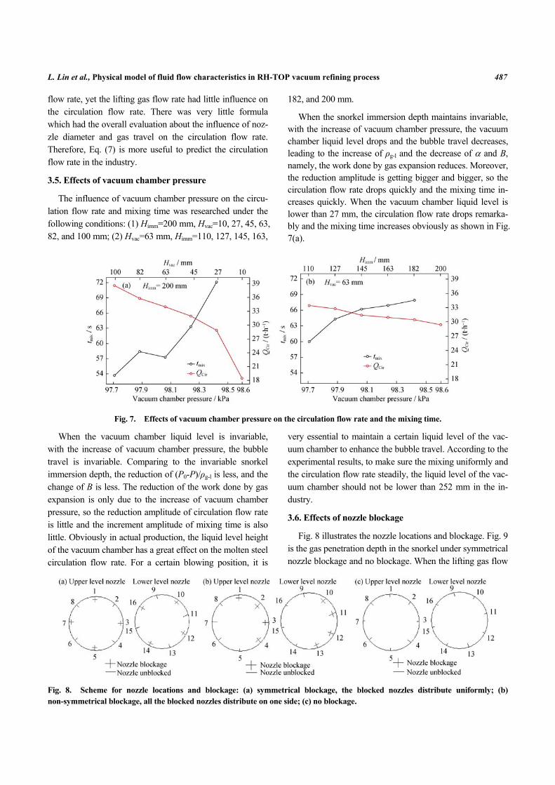
The influence of vacuum chamber pressure on the circu-lation flow rate and mixing time was researched under the following conditions: (1) Himm=200 mm, Hvac=10, 27, 45, 63, 82, and 100 mm; (2) Hvac=63 mm, Himm=110, 127, 145, 163,
182, and 200 mm.
When the snorkel immersion depth maintains invariable, with the increase of vacuum chamber pressure, the vacuum chamber liquid level drops and the bubble travel decreases, leading to the increase of ρg-l and the decrease of α and B, namely, the work done by gas expansion reduces. Moreover, the reduction amplitude is getting bigger and bigger, so the circulation flow rate drops quickly and the mixing time in-creases quickly. When the vacuum chamber liquid level is lower than 27 mm, the circulation flow rate drops remarka-bly and the mixing time increases obviously as shown in Fig. 7(a).
Fig. 7. Effects of vacuum chamber pressure on the circulation flow rate and the mixing time.
When the vacuum chamber liquid level is invariable, with the increase of vacuum chamber pressure, the bubble travel is invariable. Comparing to the invariable snorkel immersion depth, the reduction of (P0-P)/ρg-l is less, and the change of B is less. The reduction of the work done by gas expansion is only due to the increase of vacuum chamber pressure, so the reduction amplitude of circulation flow rate is little and the increment amplitude of mixing time is also little. Obviously in actual production, the liquid level height of the vacuum chamber has a great effect on the molten steel circulation flow rate. For a certain blowing position, it is
very essential to maintain a certain liquid level of the vac-uum chamber to enhance the bubble travel. According to the experimental results, to make sure the mixing uniformly and the circulation flow rate steadily, the liquid level of the vac-uum chamber should not be lower than 252 mm in the in-dustry.
3.6. Effects of nozzle blockage
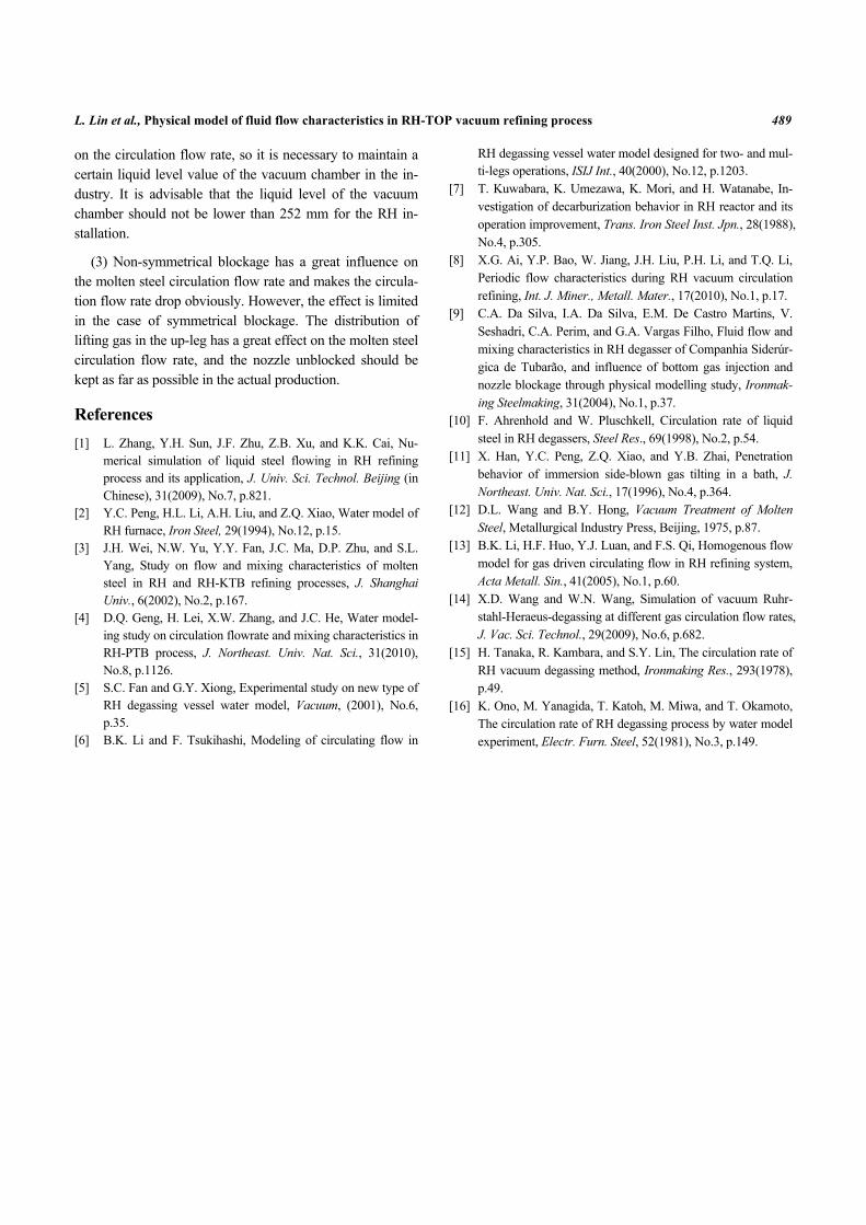
Fig. 8 illustrates the nozzle locations and blockage. Fig. 9 is the gas penetration depth in the snorkel under symmetrical nozzle blockage and no blockage. When the lifting gas flow
Fig. 8. Scheme for nozzle locations and blockage: (a) symmetrical blockage, the blocked nozzles distribute uniformly; (b) non-symmetrical blockage, all the blocked nozzles distribute on one side; (c) no blockage.

488 Int. J. Miner. Metall. Mater., Vol.19, No.6, June 2012
Fig. 9. Effects of penetration depth of lifting gas on the circu-lation flow rate in the snorkel.
rate is the same, the bubble velocity of the nozzle outlet for symmetrical blockage is twice than that for no blockage. According to Eq. (2), the gas penetration depth is a little big. However, less nozzles make the bubble quantity reduced. The circulation flow rate is influenced by the bubble pene-tration depth as well as the bubble quantity.
When the lifting gas flow rate is small, ug0 is small and weakens very quickly, the gas kinetic energy drops at the outlet, and Lp is insufficient. The bubble rises through the wall surface of the up-leg, which creates “adherent effect”, and the gas lifting function reduces seriously, which also reduce the circulation flow rate. When symmetrical block-age is applied, the positive influence of gas penetration depth increasing on the circulation flow rate is bigger than the negative influence of bubble number decreasing, so the circulation flow rate increases as the integrated performance, and this is why the circulation flow rate of symmetrical blockage is bigger than that of no blockage, when the blow-ing gas quantity is small.
However, with the increase of the lifting gas, the gas penetration depth increases; the bubble spreads to the area which is close to the up-leg central line, so the bubble quan-tity is more in the center. If there is no blockage, more noz-zles make the bubble quantity increase sharply, the gas holdup increases in the up-leg, and ρg-l decreases. Then the work done by bubble floatage and the molten steel circula-tion flow rate become bigger. Meanwhile, when symmetri-cal blockage is applied, the positive influence of gas pene-tration depth increasing on the circulation flow rate is smaller than the negative influence of bubble number de-creasing; finally, the circulation flow rate decreases as the integrated performance. So the circulation flow rate of symmetrical blockage is smaller than that of no blockage,
when the blowing gas quantity becomes bigger.
For non-symmetrical blockage, the gas blown into the up-leg spreads towards to the no blockage side, the distribu-tion of the lifting gas is extremely non-uniform in the up-leg, the turbulent flow is formed on the top of the up-leg, which seriously weakens the lifting function of gas. Compared to no blockage nozzle, the circulation flow rate of non-symme-trical blockage drops by about 20% at different lifting gas flow rates, as shown in Fig. 10.
Fig. 10. Effects of nozzle blockage on the circulation flow rate.
The result also indicates that the uniform distribution of the lifting gas in the up-leg is very important to the en-hancement of circulation flow rate. But there is a limit for compensating nozzle blockage (such as influencing the uni-form distribution of the lifting gas) by increasing the circu-lation flow rate (such as raising the gas holdup), which is similar to the research by Da Silva et al. [9]. In actual pro-duction, nozzle blockage is a common phenomenon, the maintenance should be strengthened, and the unblocked nozzle should be kept as far as possible in the industry.
4. Conclusions
(1) The circulation flow rate increases with the increase of the lifting gas flow rate, bubble travel, and up-leg internal diameter, and decreases with the decrease of nozzle diame-ter. The circulation flow rate expression is obtained for the 250-t RH device as the following equation. From the result, the lifting gas travel in the molten steel as well as the up-leg internal diameter have a great effect on the circulation flow rate; the lifting gas flow rate has little influence on the cir-culation flow rate.
7 0.405 1.211 1.616 0.518Cir-p g u Bub 0=1.137 10 .Q Q D h d− −× ⋅ ⋅ ⋅ ⋅
(2) Liquid level in the vacuum chamber has a great effect
L. Lin et al., Physical model of fluid flow characteristics in RH-TOP vacuum refining process 489
on the circulation flow rate, so it is necessary to maintain a certain liquid level value of the vacuum chamber in the in-dustry. It is advisable that the liquid level of the vacuum chamber should not be lower than 252 mm for the RH in-stallation.
(3) Non-symmetrical blockage has a great influence on the molten steel circulation flow rate and makes the circula-tion flow rate drop obviously. However, the effect is limited in the case of symmetrical blockage. The distribution of lifting gas in the up-leg has a great effect on the molten steel circulation flow rate, and the nozzle unblocked should be kept as far as possible in the actual production.
References [1] L. Zhang, Y.H. Sun, J.F. Zhu, Z.B. Xu, and K.K. Cai, Nu-
merical simulation of liquid steel flowing in RH refining process and its application, J. Univ. Sci. Technol. Beijing (in Chinese), 31(2009), No.7, p.821.
[2] Y.C. Peng, H.L. Li, A.H. Liu, and Z.Q. Xiao, Water model of RH furnace, Iron Steel, 29(1994), No.12, p.15.
[3] J.H. Wei, N.W. Yu, Y.Y. Fan, J.C. Ma, D.P. Zhu, and S.L. Yang, Study on flow and mixing characteristics of molten steel in RH and RH-KTB refining processes, J. Shanghai Univ., 6(2002), No.2, p.167.
[4] D.Q. Geng, H. Lei, X.W. Zhang, and J.C. He, Water model-ing study on circulation flowrate and mixing characteristics in RH-PTB process, J. Northeast. Univ. Nat. Sci., 31(2010), No.8, p.1126.
[5] S.C. Fan and G.Y. Xiong, Experimental study on new type of RH degassing vessel water model, Vacuum, (2001), No.6, p.35.
[6] B.K. Li and F. Tsukihashi, Modeling of circulating flow in
RH degassing vessel water model designed for two- and mul-ti-legs operations, ISIJ Int., 40(2000), No.12, p.1203.
[7] T. Kuwabara, K. Umezawa, K. Mori, and H. Watanabe, In-vestigation of decarburization behavior in RH reactor and its operation improvement, Trans. Iron Steel Inst. Jpn., 28(1988), No.4, p.305.
[8] X.G. Ai, Y.P. Bao, W. Jiang, J.H. Liu, P.H. Li, and T.Q. Li, Periodic flow characteristics during RH vacuum circulation refining, Int. J. Miner., Metall. Mater., 17(2010), No.1, p.17.
[9] C.A. Da Silva, I.A. Da Silva, E.M. De Castro Martins, V. Seshadri, C.A. Perim, and G.A. Vargas Filho, Fluid flow and mixing characteristics in RH degasser of Companhia Siderúr-gica de Tubarão, and influence of bottom gas injection and nozzle blockage through physical modelling study, Ironmak-ing Steelmaking, 31(2004), No.1, p.37.
[10] F. Ahrenhold and W. Pluschkell, Circulation rate of liquid steel in RH degassers, Steel Res., 69(1998), No.2, p.54.
[11] X. Han, Y.C. Peng, Z.Q. Xiao, and Y.B. Zhai, Penetration behavior of immersion side-blown gas tilting in a bath, J. Northeast. Univ. Nat. Sci., 17(1996), No.4, p.364.
[12] D.L. Wang and B.Y. Hong, Vacuum Treatment of Molten Steel, Metallurgical Industry Press, Beijing, 1975, p.87.
[13] B.K. Li, H.F. Huo, Y.J. Luan, and F.S. Qi, Homogenous flow model for gas driven circulating flow in RH refining system, Acta Metall. Sin., 41(2005), No.1, p.60.
[14] X.D. Wang and W.N. Wang, Simulation of vacuum Ruhr-stahl-Heraeus-degassing at different gas circulation flow rates, J. Vac. Sci. Technol., 29(2009), No.6, p.682.
[15] H. Tanaka, R. Kambara, and S.Y. Lin, The circulation rate of RH vacuum degassing method, Ironmaking Res., 293(1978), p.49.
[16] K. Ono, M. Yanagida, T. Katoh, M. Miwa, and T. Okamoto, The circulation rate of RH degassing process by water model experiment, Electr. Furn. Steel, 52(1981), No.3, p.149.