physical property measurement system - ucsb … · physical property measurement system ac...
TRANSCRIPT

Physical Property Measurement System
AC Transport Option User’s Manual
Part Number 1584-100, D-1
Quantum Design 11578 Sorrento Valley Rd. San Diego, CA 92121-1311 USA Technical support (858) 481-4400 (800) 289-6996 Fax (858) 481-7410 Fifth edition of manual completed October 2003.
Trademarks All product and company names appearing in this manual are trademarks or registered trademarks of their respective holders.
U.S. Patents 4,791,788 Method for Obtaining Improved Temperature Regulation When Using Liquid Helium Cooling 4,848,093 Apparatus and Method for Regulating Temperature in a Cryogenic Test Chamber 5,311,125 Magnetic Property Characterization System Employing a Single Sensing Coil Arrangement to Measure AC
Susceptibility and DC Moment of a Sample (patent licensed from Lakeshore) 5,647,228 Apparatus and Method for Regulating Temperature in Cryogenic Test Chamber 5,798,641 Torque Magnetometer Utilizing Integrated Piezoresistive Levers
Foreign Patents U.K. 9713380.5 Apparatus and Method for Regulating Temperature in Cryogenic Test Chamber

Quantum Design PPMS AC Transport Option User’s Manual, Rev. D-1 i October 15, 2003
C O N T E N T S
Table of Contents PREFACE Contents and Conventions............................................................................................................................... vii
P.1 Introduction ...................................................................................................................................................... vii P.2 Scope of the Manual ......................................................................................................................................... vii P.3 Contents of the Manual..................................................................................................................................... vii P.4 Conventions in the Manual .............................................................................................................................. viii
CHAPTER 1 Theory of Operation .........................................................................................................................................1-1
1.1 Introduction......................................................................................................................................................1-1 1.2 Overview of the ACT Option ..........................................................................................................................1-1 1.3 ACT Measurement Types ................................................................................................................................1-2
1.3.1 Resistivity Measurements .........................................................................................................................1-2 1.3.1.1 Harmonic Detection ...........................................................................................................................1-3
1.3.2 Hall Coefficient Measurements.................................................................................................................1-3 1.3.2.1 Additional Voltage Leads and Balancing ..........................................................................................1-4 1.3.2.2 Harmonic Detection ...........................................................................................................................1-5
1.3.3 I-V Curve Measurements ..........................................................................................................................1-6 1.3.4 Critical Current Measurements .................................................................................................................1-7
CHAPTER 2 Installation ............................................................................................................................................................2-1
2.1 Introduction......................................................................................................................................................2-1 2.2 Installation Kit Components ............................................................................................................................2-1 2.3 Installation Procedures.....................................................................................................................................2-2
2.3.1 Install the AC Board .................................................................................................................................2-2 2.3.2 Install the Model 7100 ..............................................................................................................................2-5 2.3.3 Connect the System...................................................................................................................................2-6 2.3.4 Install the Software ...................................................................................................................................2-6
CHAPTER 3 Hardware ..............................................................................................................................................................3-1
3.1 Introduction......................................................................................................................................................3-1 3.2 Model 7100 AC Transport Controller..............................................................................................................3-1
3.2.1 Electrical Current Operating Modes .........................................................................................................3-2 3.2.2 Output Range ............................................................................................................................................3-3 3.2.3 Gain Settings.............................................................................................................................................3-3 3.2.4 Automatic Thermal Cutoff ........................................................................................................................3-4
3.3 Model 6000 AC Board.....................................................................................................................................3-5 3.4 Cables and Jumpers..........................................................................................................................................3-5 3.5 ACT Sample Pucks ..........................................................................................................................................3-6
Contents Table of Contents
ii PPMS AC Transport Option User’s Manual, Rev. D-1 Quantum Design October 15, 2003
CHAPTER 4 Software................................................................................................................................................................. 4-1
4.1 Introduction ..................................................................................................................................................... 4-1 4.2 Overview of the ACT Software....................................................................................................................... 4-1
4.2.1 AC Transport Control Center ................................................................................................................... 4-2 4.2.1.1 Install Tab.......................................................................................................................................... 4-2 4.2.1.2 Data File Tab ..................................................................................................................................... 4-3 4.2.1.3 Sample Tabs ...................................................................................................................................... 4-4 4.2.1.4 Waveform Tab................................................................................................................................... 4-5 4.2.1.5 Configure Tab.................................................................................................................................... 4-6 4.2.1.6 Measurement Command Buttons....................................................................................................... 4-6
4.3 ACT Status Log............................................................................................................................................... 4-7 4.4 ACT Data Files................................................................................................................................................ 4-8
4.4.1 Creating an ACT Measurement Data File ................................................................................................ 4-9
CHAPTER 5 Measurements ..................................................................................................................................................... 5-1
5.1 Introduction ..................................................................................................................................................... 5-1 5.2 Sample-Mounting Procedures ......................................................................................................................... 5-1 5.3 ACT Measurements......................................................................................................................................... 5-3
5.3.1 Taking Resistivity Measurements in Immediate Mode ............................................................................ 5-3 5.3.1.1 Prepare for the Measurement............................................................................................................. 5-3 5.3.1.2 Define the Measurement.................................................................................................................... 5-4 5.3.1.3 Run the Measurement ........................................................................................................................ 5-5
5.3.2 Taking Five-Wire Hall Measurements in Immediate Mode ..................................................................... 5-5 5.3.2.1 Prepare for the Measurement............................................................................................................. 5-5 5.3.2.2 Null the Offset Voltage...................................................................................................................... 5-6 5.3.2.3 Define the Measurement.................................................................................................................... 5-6 5.3.2.4 Run the Measurement ........................................................................................................................ 5-8
5.3.3 Taking I-V Curve Measurements in Immediate Mode ............................................................................. 5-8 5.3.3.1 Prepare for the Measurement............................................................................................................. 5-8 5.3.3.2 Define the Measurement.................................................................................................................... 5-8 5.3.3.3 Run the Measurement ...................................................................................................................... 5-10
5.3.4 Taking Critical Current Measurements in Immediate Mode .................................................................. 5-10 5.3.4.1 Prepare for the Measurement........................................................................................................... 5-10 5.3.4.2 Define the Measurement.................................................................................................................. 5-11 5.3.4.3 Run the Measurement ...................................................................................................................... 5-11
5.3.5 Taking Resistivity Measurements in Sequence Mode ............................................................................ 5-12 5.3.5.1 Create the Sequence Command ....................................................................................................... 5-12 5.3.5.2 Prepare for the Measurement........................................................................................................... 5-13 5.3.5.3 Run the Sequence ............................................................................................................................ 5-14
5.3.6 Taking Five-Wire Hall Measurements in Sequence Mode..................................................................... 5-14 5.3.6.1 Create the Sequence Command ....................................................................................................... 5-14 5.3.6.2 Prepare for the Measurement........................................................................................................... 5-15 5.3.6.3 Null the Offset Voltage.................................................................................................................... 5-15 5.3.6.4 Run the Sequence ............................................................................................................................ 5-16
5.3.7 Taking I-V Curve Measurements in Sequence Mode............................................................................. 5-16 5.3.7.1 Create the Sequence Command ....................................................................................................... 5-16 5.3.7.2 Prepare for the Measurement........................................................................................................... 5-17 5.3.7.3 Run the Sequence ............................................................................................................................ 5-17
5.3.8 Taking Critical Current Measurements in Sequence Mode.................................................................... 5-18 5.3.8.1 Create the Sequence Command ....................................................................................................... 5-18 5.3.8.2 Prepare for the Measurement........................................................................................................... 5-19 5.3.8.3 Run the Sequence ............................................................................................................................ 5-19
Contents Table of Contents
Quantum Design PPMS AC Transport Option User’s Manual, Rev. D-1 iii October 15, 2003
CHAPTER 6 Operation with the Helium-3 System.........................................................................................................6-1
6.1 Introduction......................................................................................................................................................6-1 6.2 Overview of ACT Operation with the Helium-3 System.................................................................................6-1 6.3 ACT Measurements with the Helium-3 System...............................................................................................6-2
6.3.1 Measurement Setup...................................................................................................................................6-2 6.3.1.1 Prepare for the Measurement .............................................................................................................6-2 6.3.1.2 Install the Sample...............................................................................................................................6-3 6.3.1.3 Start Up the Software.........................................................................................................................6-3
6.3.2 Performing Measurements ........................................................................................................................6-4 6.4 Interconnection Tables for the ACT/Helium-3 Probe Cable ...........................................................................6-5
CHAPTER 7 Operation with the Horizontal Rotator.....................................................................................................7-1
7.1 Introduction......................................................................................................................................................7-1 7.2 Overview of ACT Operation with the Horizontal Rotator...............................................................................7-1 7.3 Rotator Thermometer Configuration................................................................................................................7-2
7.3.1 Turning Off UserTemp .............................................................................................................................7-3 7.4 ACT Measurements with the Horizontal Rotator ............................................................................................7-4 7.5 Interconnection Tables for the ACT/Horizontal Rotator Probe Cable.............................................................7-5
APPENDIX A Connections, Ports, and Pinouts .................................................................................................................A-1
A.1 Introduction....................................................................................................................................................A-1 A.2 System Connections .......................................................................................................................................A-1 A.3 Model 7100 Rear Panel Ports.........................................................................................................................A-2 A.4 Pinout Tables..................................................................................................................................................A-3
A.4.1 Sample Connections................................................................................................................................A-3 A.4.2 Drive Access and Monitor Connections..................................................................................................A-5 A.4.3 AC Board Connections ...........................................................................................................................A-6
APPENDIX B Error and Warning Messages ...................................................................................................................... B-1
B.1 Introduction .................................................................................................................................................... B-1 B.2 Warning Messages ......................................................................................................................................... B-1 B.3 Error Messages............................................................................................................................................... B-2
APPENDIX C Measuring the Hall Coefficient of the Copper Hall Sample ............................................................ C-1
C.1 Introduction .................................................................................................................................................... C-1 C.2 Verifying the Hall Effect Measurement ......................................................................................................... C-1
References ............................................................................................................................................. References-1
Index................................................................................................................................................................. Index-1
Contents Table of Figures
iv PPMS AC Transport Option User’s Manual, Rev. D-1 Quantum Design October 15, 2003
Figures Figure 1-1. Leads for Four-Wire AC Resistivity Measurement ............................................................................... 1-2 Figure 1-2. Common Lead Arrangement for Bar-Shaped Samples.......................................................................... 1-3 Figure 1-3. Four-Wire Hall Effect Measurement for Sample with Negative Charge Carriers ................................. 1-4 Figure 1-4. Leads Attached for Four-Wire and Five-Wire Hall Coefficient Measurements.................................... 1-5 Figure 1-5. Current through Sample during I-V Traces Can Be Ramped Up or Down ........................................... 1-6 Figure 1-6. Example I-V Curve................................................................................................................................ 1-6 Figure 2-1. Remove the Top Cover of the Model 6000 ........................................................................................... 2-3 Figure 2-2. Top View of Rear Portion of Model 6000 Interior ................................................................................ 2-4 Figure 2-3. Removing the Blank Panel .................................................................................................................... 2-5 Figure 2-4. ACT Connections .................................................................................................................................. 2-6 Figure 3-1. Front Panel on Model 7100 AC Transport Controller ........................................................................... 3-1 Figure 3-2. Available Current As a Function of Voltage Drop Across the Current Leads. ..................................... 3-2 Figure 3-3. ACT “Y” Connection Cable .................................................................................................................. 3-5 Figure 3-4. ACT Sample Puck ................................................................................................................................. 3-6 Figure 4-1. Install Tab in AC Transport Control Center .......................................................................................... 4-2 Figure 4-2. Data File Tab in AC Transport Control Center ..................................................................................... 4-3 Figure 4-3. Sample Tabs in AC Transport Control Center....................................................................................... 4-4 Figure 4-4. Waveform Tab in AC Transport Control Center ................................................................................... 4-5 Figure 4-5. Configure Tab in AC Transport Control Center .................................................................................... 4-6 Figure 4-6. ACT Status Log ..................................................................................................................................... 4-7 Figure 5-1. Wiring Examples for ACT Measurements ............................................................................................ 5-1 Figure 5-2. Dialog Box for Defining Resistivity Measurement in Immediate Mode ............................................... 5-4 Figure 5-3. Balance Meter Dialog Box .................................................................................................................... 5-6 Figure 5-4. Dialog Box for Defining Hall Coefficient Measurement in Immediate Mode ...................................... 5-7 Figure 5-5. Dialog Box for Defining I-V Curve Measurement in Immediate Mode................................................ 5-9 Figure 5-6. Dialog Box for Defining Critical Current Measurement in Immediate Mode ..................................... 5-11 Figure 5-7. Sample 1 Tab in Dialog Box for Defining Resistivity Measurement in Sequence Mode.................... 5-13 Figure 5-8. PPMS Data Tab in Dialog Box for Defining Resistivity Measurement in Sequence Mode................ 5-13 Figure 5-9. Sample 1 Tab in Dialog Box for Defining Hall Coefficient Measurement in Sequence Mode........... 5-15 Figure 5-10. Sample 1 Tab in Dialog Box for Defining I-V Curve Measurement in Sequence Mode .................. 5-17 Figure 5-11. Sample 1 Tab in Dialog Box for Defining Critical Current Measurement in Sequence Mode ......... 5-18 Figure 6-1. ACT/Helium-3 Probe Cable .................................................................................................................. 6-2 Figure 6-2. Sample-Wiring Diagrams for the Helium-3 Option .............................................................................. 6-3 Figure 7-1. ACT/Horizontal Rotator Probe Cable.................................................................................................... 7-2 Figure 7-2. Sample-Wiring Diagrams for the Horizontal Rotator Option................................................................ 7-4 Figure A-1. ACT Connections ................................................................................................................................ A-1 Figure A-2. Rear Panel on Model 7100 AC Transport Controller .......................................................................... A-2 Figure A-3. Illustration of ACT Sample Connections............................................................................................. A-4 Figure C-1. Copper Sample for Verifying the Hall Effect Measurement.................................................................C-1
Contents Table of Tables
Quantum Design PPMS AC Transport Option User’s Manual, Rev. D-1 v October 15, 2003
Tables Table 3-1. Model 7100 Drive Source Impedance in Low-Impedance Mode............................................................3-3 Table 3-2. Voltage Detection Gain Stages................................................................................................................3-4 Table 4-1. Software Files Required to Operate ACT Option....................................................................................4-1 Table 6-1. Pin Mapping for Helium-3 Thermometer Wiring....................................................................................6-5 Table 6-2. Pin Mapping for ACT Drive Current Wiring ..........................................................................................6-5 Table 6-3. Pin Mapping for ACT Voltage Readback Wiring ...................................................................................6-5 Table 7-1. Pin Mapping for P2−System Bridge Port on Model 6000.......................................................................7-5 Table 7-2. Pin Mapping for P1−Sample Current Out Port on Model 7100 ..............................................................7-5 Table 7-3. Pin Mapping for P5−Sample Voltage In Port on Model 7100 ................................................................7-5 Table A-1. Electrical Ports on Model 7100 Rear Panel ...........................................................................................A-2 Table A-2. Connections from Sample to Model 7100 .............................................................................................A-3 Table A-3. Drive Access and Monitor Connections ................................................................................................A-5 Table A-4. Connections between P3−Analog Interface Port and P3−Option Port ..................................................A-6 Table A-5. Connections between P4−Digital Interface Port and P3−Option Port...................................................A-6
Quantum Design PPMS AC Transport Option User’s Manual, Rev. D-1 vii October 15, 2003
P R E F A C E
Contents and Conventions
P.1 Introduction This preface contains the following information:
• Section P.2 discusses the overall scope of the manual.
• Section P.4 illustrates and describes conventions that appear in the manual.
• Section P.3 briefly summarizes the contents of the manual.
P.2 Scope of the Manual This manual discusses the operation of the AC Transport Measurement System (ACT) option hardware and software and explains how to take ACT measurements.
This manual does not provide detailed information about the PPMS MultiVu software application, which is the software running the Physical Property Measurement System (PPMS). The ACT option software is integrated into PPMS MultiVu. The Physical Property Measurement System: PPMS MultiVu Application User’s Manual discusses the functionality of PPMS MultiVu.
P.3 Contents of the Manual • Chapter 1 presents an overview of the
ACT option and ACT measurements. • Chapter 6 explains how to use the
ACT option with the Helium-3 option. • Chapter 2 explains how to install the
ACT option. • Chapter 7 explains how to use the
ACT option with the Horizontal Rotator. • Chapter 3 discusses the operation of
the ACT hardware. • Appendix A describes and illustrates
the ACT electrical ports. • Chapter 4 discusses the ACT software
and ACT data files. • Appendix B lists error and warning
messages. • Chapter 5 explains how to mount
samples and take ACT measurements.

Section P.4 Preface Conventions in the Manual Contents and Conventions
viii PPMS AC Transport Option User’s Manual, Rev. D-1 Quantum Design October 15, 2003
P.4 Conventions in the Manual File menu Bold text distinguishes the names of menus, options, buttons, and panels appearing
on the PC monitor or on the Model 6000 PPMS Controller LCD screen.
File Open The symbol indicates that you select multiple, nested software options.
STATUS Bold text and all capital letters distinguish the names of keys located on the front panel of the Model 6000 PPMS Controller.
.dat The Courier font distinguishes characters you enter from the PC keyboard or from the Model 6000 PPMS Controller front panel. The Courier font also distinguishes code and the names of files and directories.
<Enter> Angle brackets distinguish the names of keys located on the PC keyboard.
<Alt+Enter> A plus sign connecting the names of two or more keys distinguishes keys you press simultaneously.
A pointing hand introduces a supplementary note.
Caution! Introduces a cautionary note.
Warning! Introduces a warning.
Quantum Design PPMS AC Transport Option User’s Manual, Rev. D-1 1-1 October 15, 2003
C H A P T E R 1
Theory of Operation
1.1 Introduction This chapter contains the following information:
• Section 1.2 presents an overview of the AC Transport Measurement System.
• Section 1.3 explains the theory of each AC Transport measurement type.
1.2 Overview of the ACT Option The Quantum Design AC Transport Measurement System (ACT) option incorporates a precision current source and a precision voltmeter in a package configured for use with the base Physical Property Measurement System (PPMS) platform. The precision current source has a resolution of 0.02 µA and a maximum current of 2 A. The precision voltage detector has a similarly sized range. The ACT option can thus support several different types of electrical transport current measurements, including measurements that require ramping a DC current. Measurements are typically made by passing a known current through the sample and measuring the voltage drop across the sample in one direction. The ACT option can be used with samples mounted on sample pucks or sample rotators.
The ACT option can supply an AC bias current from 1 Hz up to 1 kHz and can therefore provide greater measurement sensitivity than DC instruments because signal filtering can be employed. The quantity of interest is generally a component with a form similar to the driving form and a known frequency, so all other components of the sample signal can be subtracted off, eliminating frequency-dependent noise, DC offset, and instrumental drift. In the ACT option, digital filtering precisely isolates the sample signal.
The ACT software module is integrated into the PPMS MultiVu software application, which controls and monitors the PPMS hardware. While you work with the ACT option, you may use any PPMS MultiVu commands. PPMS MultiVu and ACT software commands can fully automate system operation, so you can run a wide range of measurements without being present in the laboratory. The Physical Property Measurement System: PPMS MultiVu Application User’s Manual discusses PPMS MultiVu in detail.
Section 1.3 Chapter 1 ACT Measurement Types Theory of Operation
1-2 PPMS AC Transport Option User’s Manual, Rev. D-1 Quantum Design October 15, 2003
1.3 ACT Measurement Types The ACT option supports four types of electrical transport current measurements:
• Resistivity • Hall Coefficient • I-V Curve • Critical Current
Resistivity, I-V curve, and critical current measurements measure the resistive voltage of the sample. I-V curve and critical current measurements are basically variants of a resistivity measurement. All three of these measurement types require the same lead connections to the sample. Hall coefficient measurements, however, measure the sample’s Hall voltage and therefore require a different config-uration for the sample lead connections.
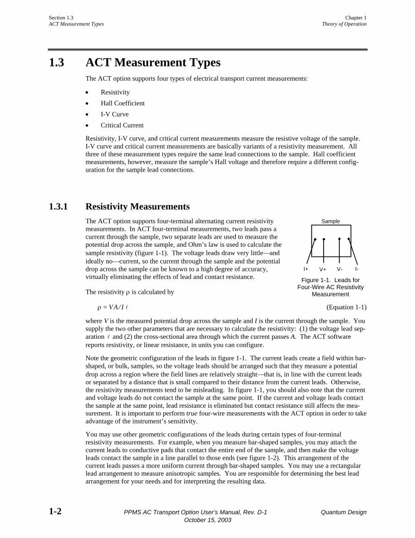
1.3.1 Resistivity Measurements The ACT option supports four-terminal alternating current resistivity measurements. In ACT four-terminal measurements, two leads pass a current through the sample, two separate leads are used to measure the potential drop across the sample, and Ohm’s law is used to calculate the sample resistivity (figure 1-1). The voltage leads draw very little⎯and ideally no⎯current, so the current through the sample and the potential drop across the sample can be known to a high degree of accuracy, virtually eliminating the effects of lead and contact resistance.
The resistivity ρ is calculated by
ρ = VA/I l (Equation 1-1)
where V is the measured potential drop across the sample and I is the current through the sample. You supply the two other parameters that are necessary to calculate the resistivity: (1) the voltage lead sep-aration l and (2) the cross-sectional area through which the current passes A. The ACT software reports resistivity, or linear resistance, in units you can configure.
Note the geometric configuration of the leads in figure 1-1. The current leads create a field within bar-shaped, or bulk, samples, so the voltage leads should be arranged such that they measure a potential drop across a region where the field lines are relatively straight⎯that is, in line with the current leads or separated by a distance that is small compared to their distance from the current leads. Otherwise, the resistivity measurements tend to be misleading. In figure 1-1, you should also note that the current and voltage leads do not contact the sample at the same point. If the current and voltage leads contact the sample at the same point, lead resistance is eliminated but contact resistance still affects the mea-surement. It is important to perform true four-wire measurements with the ACT option in order to take advantage of the instrument’s sensitivity.
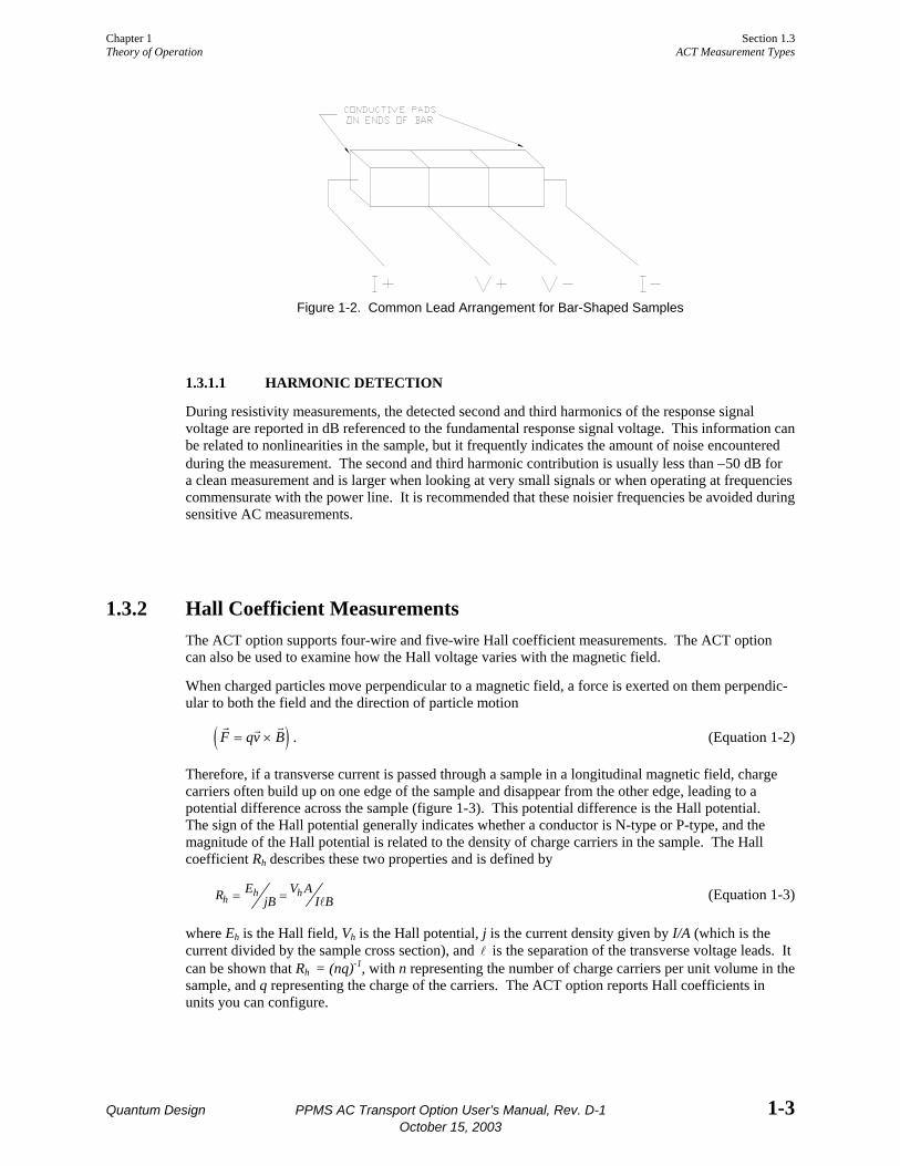
You may use other geometric configurations of the leads during certain types of four-terminal resistivity measurements. For example, when you measure bar-shaped samples, you may attach the current leads to conductive pads that contact the entire end of the sample, and then make the voltage leads contact the sample in a line parallel to those ends (see figure 1-2). This arrangement of the current leads passes a more uniform current through bar-shaped samples. You may use a rectangular lead arrangement to measure anisotropic samples. You are responsible for determining the best lead arrangement for your needs and for interpreting the resulting data.
Sample
I+ I-V+ V- Figure 1-1. Leads for
Four-Wire AC Resistivity Measurement
Chapter 1 Section 1.3 Theory of Operation ACT Measurement Types
Quantum Design PPMS AC Transport Option User’s Manual, Rev. D-1 1-3 October 15, 2003
Figure 1-2. Common Lead Arrangement for Bar-Shaped Samples
1.3.1.1 HARMONIC DETECTION
During resistivity measurements, the detected second and third harmonics of the response signal voltage are reported in dB referenced to the fundamental response signal voltage. This information can be related to nonlinearities in the sample, but it frequently indicates the amount of noise encountered during the measurement. The second and third harmonic contribution is usually less than −50 dB for a clean measurement and is larger when looking at very small signals or when operating at frequencies commensurate with the power line. It is recommended that these noisier frequencies be avoided during sensitive AC measurements.
1.3.2 Hall Coefficient Measurements The ACT option supports four-wire and five-wire Hall coefficient measurements. The ACT option can also be used to examine how the Hall voltage varies with the magnetic field.
When charged particles move perpendicular to a magnetic field, a force is exerted on them perpendic-ular to both the field and the direction of particle motion
( )r r rF qv B= × . (Equation 1-2)
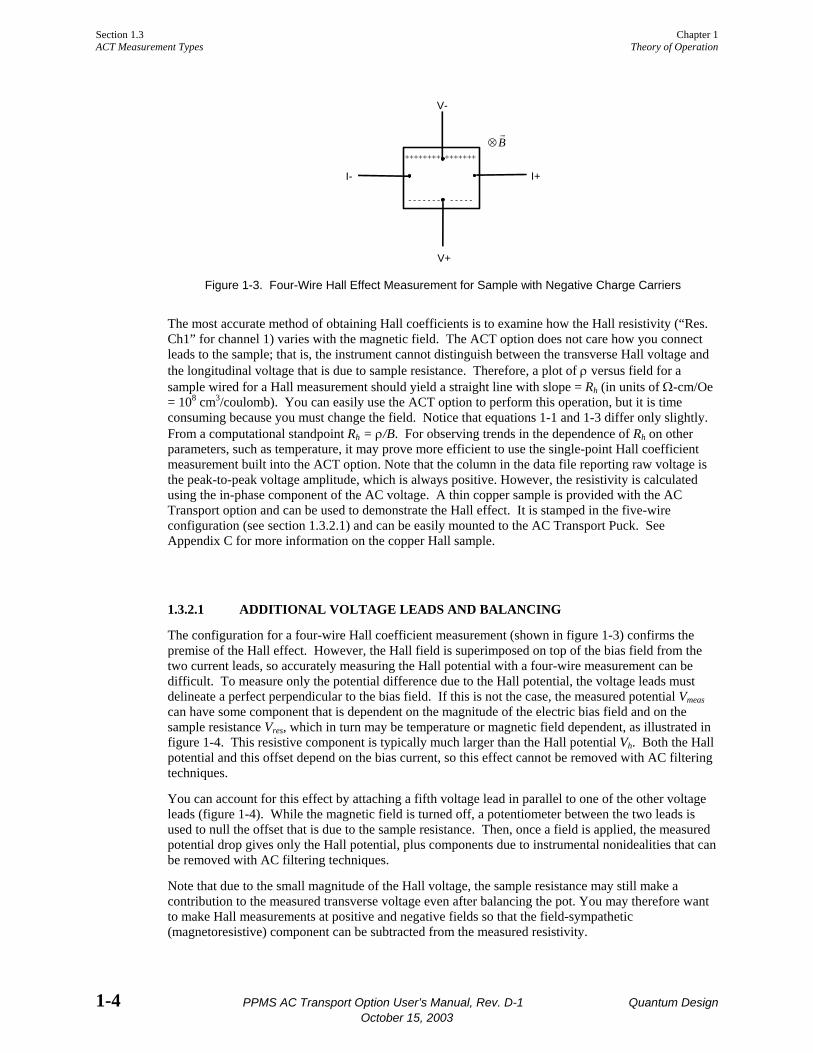
Therefore, if a transverse current is passed through a sample in a longitudinal magnetic field, charge carriers often build up on one edge of the sample and disappear from the other edge, leading to a potential difference across the sample (figure 1-3). This potential difference is the Hall potential. The sign of the Hall potential generally indicates whether a conductor is N-type or P-type, and the magnitude of the Hall potential is related to the density of charge carriers in the sample. The Hall coefficient Rh describes these two properties and is defined by
R EjB
V AI Bh h h= = l (Equation 1-3)
where Eh is the Hall field, Vh is the Hall potential, j is the current density given by I/A (which is the current divided by the sample cross section), and l is the separation of the transverse voltage leads. It can be shown that Rh = (nq)-1, with n representing the number of charge carriers per unit volume in the sample, and q representing the charge of the carriers. The ACT option reports Hall coefficients in units you can configure.
Section 1.3 Chapter 1 ACT Measurement Types Theory of Operation
1-4 PPMS AC Transport Option User’s Manual, Rev. D-1 Quantum Design October 15, 2003
I- I+
V-
V+
⊗rB
++++++++ +++++++
- - - - - - - - - - - -
Figure 1-3. Four-Wire Hall Effect Measurement for Sample with Negative Charge Carriers
The most accurate method of obtaining Hall coefficients is to examine how the Hall resistivity (“Res. Ch1” for channel 1) varies with the magnetic field. The ACT option does not care how you connect leads to the sample; that is, the instrument cannot distinguish between the transverse Hall voltage and the longitudinal voltage that is due to sample resistance. Therefore, a plot of ρ versus field for a sample wired for a Hall measurement should yield a straight line with slope = Rh (in units of Ω-cm/Oe = 108 cm3/coulomb). You can easily use the ACT option to perform this operation, but it is time consuming because you must change the field. Notice that equations 1-1 and 1-3 differ only slightly. From a computational standpoint Rh = ρ/B. For observing trends in the dependence of Rh on other parameters, such as temperature, it may prove more efficient to use the single-point Hall coefficient measurement built into the ACT option. Note that the column in the data file reporting raw voltage is the peak-to-peak voltage amplitude, which is always positive. However, the resistivity is calculated using the in-phase component of the AC voltage. A thin copper sample is provided with the AC Transport option and can be used to demonstrate the Hall effect. It is stamped in the five-wire configuration (see section 1.3.2.1) and can be easily mounted to the AC Transport Puck. See Appendix C for more information on the copper Hall sample.
1.3.2.1 ADDITIONAL VOLTAGE LEADS AND BALANCING
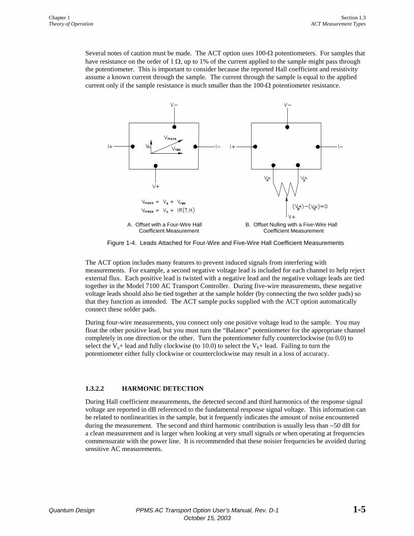
The configuration for a four-wire Hall coefficient measurement (shown in figure 1-3) confirms the premise of the Hall effect. However, the Hall field is superimposed on top of the bias field from the two current leads, so accurately measuring the Hall potential with a four-wire measurement can be difficult. To measure only the potential difference due to the Hall potential, the voltage leads must delineate a perfect perpendicular to the bias field. If this is not the case, the measured potential Vmeas can have some component that is dependent on the magnitude of the electric bias field and on the sample resistance Vres, which in turn may be temperature or magnetic field dependent, as illustrated in figure 1-4. This resistive component is typically much larger than the Hall potential Vh. Both the Hall potential and this offset depend on the bias current, so this effect cannot be removed with AC filtering techniques.
You can account for this effect by attaching a fifth voltage lead in parallel to one of the other voltage leads (figure 1-4). While the magnetic field is turned off, a potentiometer between the two leads is used to null the offset that is due to the sample resistance. Then, once a field is applied, the measured potential drop gives only the Hall potential, plus components due to instrumental nonidealities that can be removed with AC filtering techniques.
Note that due to the small magnitude of the Hall voltage, the sample resistance may still make a contribution to the measured transverse voltage even after balancing the pot. You may therefore want to make Hall measurements at positive and negative fields so that the field-sympathetic (magnetoresistive) component can be subtracted from the measured resistivity.
Chapter 1 Section 1.3 Theory of Operation ACT Measurement Types
Quantum Design PPMS AC Transport Option User’s Manual, Rev. D-1 1-5 October 15, 2003
Several notes of caution must be made. The ACT option uses 100-Ω potentiometers. For samples that have resistance on the order of 1 Ω, up to 1% of the current applied to the sample might pass through the potentiometer. This is important to consider because the reported Hall coefficient and resistivity assume a known current through the sample. The current through the sample is equal to the applied current only if the sample resistance is much smaller than the 100-Ω potentiometer resistance.
A. Offset with a Four-Wire Hall Coefficient Measurement
B. Offset Nulling with a Five-Wire Hall Coefficient Measurement
Figure 1-4. Leads Attached for Four-Wire and Five-Wire Hall Coefficient Measurements
The ACT option includes many features to prevent induced signals from interfering with measurements. For example, a second negative voltage lead is included for each channel to help reject external flux. Each positive lead is twisted with a negative lead and the negative voltage leads are tied together in the Model 7100 AC Transport Controller. During five-wire measurements, these negative voltage leads should also be tied together at the sample holder (by connecting the two solder pads) so that they function as intended. The ACT sample pucks supplied with the ACT option automatically connect these solder pads.
During four-wire measurements, you connect only one positive voltage lead to the sample. You may float the other positive lead, but you must turn the “Balance” potentiometer for the appropriate channel completely in one direction or the other. Turn the potentiometer fully counterclockwise (to 0.0) to select the Va+ lead and fully clockwise (to 10.0) to select the Vb+ lead. Failing to turn the potentiometer either fully clockwise or counterclockwise may result in a loss of accuracy.
1.3.2.2 HARMONIC DETECTION
During Hall coefficient measurements, the detected second and third harmonics of the response signal voltage are reported in dB referenced to the fundamental response signal voltage. This information can be related to nonlinearities in the sample, but it frequently indicates the amount of noise encountered during the measurement. The second and third harmonic contribution is usually less than −50 dB for a clean measurement and is larger when looking at very small signals or when operating at frequencies commensurate with the power line. It is recommended that these noisier frequencies be avoided during sensitive AC measurements.

Section 1.3 Chapter 1 ACT Measurement Types Theory of Operation
1-6 PPMS AC Transport Option User’s Manual, Rev. D-1 Quantum Design October 15, 2003
1.3.3 I-V Curve Measurements The ACT option performs current versus voltage traces for any sample or device wired to the Model 7100 AC Transport Controller. Physical connections to the sample are made just as they are made for resistivity measurements (see section 1.3.1). The DC current through the sample is ramped up or down in small discrete steps; up to 256 steps per quadrant are allowed. The current may start at zero and ramp up to a specified maximum positive or negative current, or it may start at the specified maximum current and ramp down to zero. As the current changes, the voltage drop across the sample is measured and recorded. Measurements are digital, so a continuous trace is not actually performed. A discrete number of current and voltage readings is taken throughout the current ramp pattern, and a plot of V versus I is then generated.
Figure 1-5. The current through the sample during I-V traces can be ramped up to or down from a specified maximum current. An I-V trace may contain any portion of the ramp sequence shown to the left, providing that it begins and ends at +I max, −I max, or zero.
I-V plots can help illustrate the behavior of a sample or device and may be especially interesting when nonlinear behavior exists. Figure 1-6 shows a plot of I-V data for a diode at three different tempera-tures. The data was obtained by starting at zero current and ramping up to 100 µA. Origin was used to plot the data.
0.0 0.2 0.4 0.6 0.8 1.0 1.2
0.0
2.0x10⁻⁵
4.0x10⁻⁵
6.0x10⁻⁵
8.0x10⁻⁵
1.0x10⁻⁴ 150 K 50 K100 K
I-V Trace for a Diode at 3 Different TemperaturesUsing the Quantum Design AC Transport
Curre
nt/A
Voltage/V
Figure 1-6. Example I-V Curve
When the ACT software is started, it automatically measures the power line frequency. Each I-V data point is obtained over an integral number of line cycles to help reject power line noise. The zero-excitation baseline voltage may also be measured prior to each I-V curve measurement and subtracted from the entire set of I-V data by using the Remove Voltage Offsets setting.

Chapter 1 Section 1.3 Theory of Operation ACT Measurement Types
Quantum Design PPMS AC Transport Option User’s Manual, Rev. D-1 1-7 October 15, 2003
1.3.4 Critical Current Measurements As an ohm meter already set up to measure samples within the thermally controlled environment of the PPMS, the ACT option provides a convenient method of determining the critical current of samples. Physical connections to the sample for critical current measurements are made just as they are made for resistivity measurements (see section 1.3.1).
A major concern when measuring critical current in many superconducting samples is passing too much power through them once they become resistive. Superconductors can support only a finite amount of supercurrent. Once the current in a superconductor exceeds a certain value, the material breaks down and becomes nonsuperconducting, or resistive. The current at which this occurs in a given superconductor is the critical current.
The ACT system provides power limiting through the sample during critical current measurements so that delicate samples, such as thin films, are not destroyed. The current through the sample is stepped up by the digital signal processor (DSP) in small, discrete steps towards a specified maximum current. As the current increases, the voltage drop across the sample is monitored. As long as the sample remains superconducting, the measured voltage should be zero. When the sample becomes resistive, the current through it generates a potential difference across the sample. The ACT system averages this measured potential over a designated length of time in order to filter out noise. Once the specified small critical voltage is found, the current is shut off. The ACT software reports the current at which the ramp is stopped. The response time is approximately 40 microseconds when using the short averaging time, and roughly 5.2 milliseconds when using the long averaging time. To help reduce the effects of noise on the critical current measurement, you may also specify an averaging time of one power line cycle, in which case the response time depends on the line frequency. The power line cycle setting has the longest response time.

Quantum Design PPMS AC Transport Option User’s Manual, Rev. D-1 2-1 October 15, 2003
C H A P T E R 2
Installation
2.1 Introduction This chapter contains the following information:
• Section 2.2 lists the components in the ACT installation kit.
• Section 2.3 explains how to install the ACT option.
NOTE
If your PPMS was ordered with the ACT option, the ACT hardware and software were installed at the factory. You do not need to refer to these installation instructions.
2.2 Installation Kit Components The ACT installation kit contains the following items:
Model 7100 AC Transport Controller AC board with two 3/8-in. screws, four 3/16-in. nuts, four 3/16-in. lock washers, and
one ribbon cable Three connection cables: one 9-pin cable, one 15-pin cable, and one “Y” cable 15-pin “D” shell connector with two jumpers inserted in it Power cord 44.7 cm × 48.3 cm (17.6 in. × 19 in.) Masonite blank panel for older PPMS cabinets Three ACT sample pucks with mounting circuit boards Overlay for PPMS desktop puck box 90-mm (3.5-in.) disks containing necessary software and calibration files
Contact Quantum Design if any of these items are missing from the installation kit.

Section 2.3 Chapter 2 Installation Procedures Installation
2-2 PPMS AC Transport Option User’s Manual, Rev. D-1 Quantum Design October 15, 2003
2.3 Installation Procedures ACT option installation consists of the following procedures: (1) installing the AC board in the Model 6000 PPMS Controller, (2) installing the Model 7100 AC Transport Controller in the PPMS electronics cabinet, (3) attaching the electrical cables, and (4) installing the software on the host computer.
You need the following tools to install the ACT option:
Phillips-head screwdriver 3/16-in. socket driver or needle-nose pliers or pair of blunt tweezers
2.3.1 Install the AC Board The AC board used with the ACT option is essentially the same board used with the PPMS AC Measurement System (ACMS) option. However, even if the ACMS option is already installed on your system, you must install the new AC board because each board is calibrated to work with the individual ACMS or ACT hardware.
Caution! Static discharge can damage components in the Model 6000. Before you touch the AC board or any other component inside the Model 6000, ground yourself by touching the metal back or metal side panel of the Model 6000 case. In addition, limit your movement during installation and whenever you handle the AC board; movement increases the possibility of static discharge.
Complete the following steps to install the AC board:
1. Set the system magnetic field to zero (in persistent mode) and wait for the field to reach zero. 2. Select CTRL 1. Interactive Control 8. Shutdown Mode from the Model 6000 front panel.
The PPMS enters shutdown mode. 3. Use the switch on the front panel of the Model 6000 to turn off the Model 6000. Do not turn off
the vacuum pump or any other electronics in the PPMS electronics cabinet. 4. Remove all stray equipment from the top of the electronics cabinet. 5. Remove the top of the electronics cabinet by lifting it up and off the cabinet. 6. Remove the Model 6000 top cover. Refer to figure 2-1 and do the following: (a) unscrew the
two screws on the top rear of the Model 6000 and (b) slide the top cover towards the rear of the Model 6000 and out of the cover groove.
Caution! Work carefully while the cover is off the top of the Model 6000, and avoid dropping hardware inside the unit. Any hardware dropped inside the Model 6000 must be retrieved before power may be restored to the Model 6000.

Chapter 2 Section 2.3 Installation Installation Procedures
Quantum Design PPMS AC Transport Option User’s Manual, Rev. D-1 2-3 October 15, 2003
Figure 2-1. Remove the top cover of the Model 6000 by removing the two screws and sliding the cover towards the back of the controller.
7. Unscrew the two rear panel screws that hold the blank aluminum plate around the “P3−Option” port on the rear of the Model 6000, and then remove the plate.
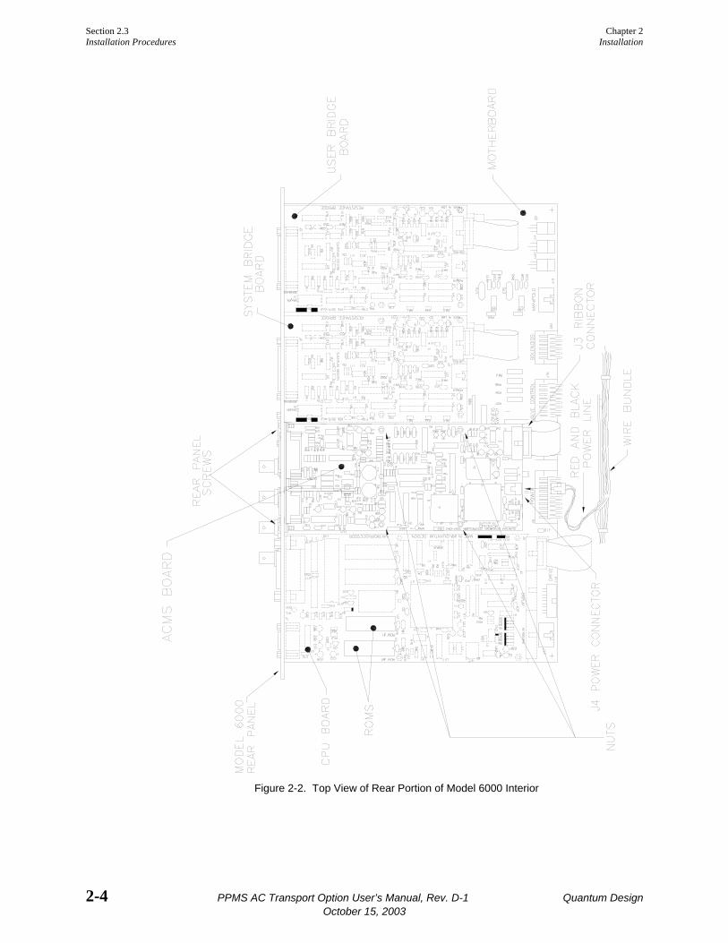
8. Note whether an AC board is installed in the “P3−Option” slot in the Model 6000. If an AC board is installed, remove it as follows: (a) remove the four nuts that hold the AC board to the posts inside the Model 6000, and then (b) remove the two rear panel screws. Refer to figure 2-2 on the following page.
9. Lay the new AC board on the posts behind the “P3−Option” slot. Position the board so that the two “D” shell connectors on the board protrude through the “P3−Option” port.
10. Install the two rear panel screws on either side of the “P3−Option” port in order to secure the AC board. Refer to figure 2-2.
11. Place the four lock washers on the posts and screw the AC board into place by screwing the nuts supplied with the board onto the four posts. Use a nut driver or a set of tweezers and needle-nose pliers, if necessary.
12. Connect the ribbon cable from the “J3” connector on the AC board to the “J15 Options” connector on the motherboard. The “J15 Options” connector is just below the AC board. Refer to figure 2-2.
13. Connect the red and black power line from the wire bundle underneath the front of the motherboard to the “J4” power connector. Refer to figure 2-2.
14. Verify that the two EPROMs on the CPU board are dated 3/22/96 or later. If the EPROMS are dated earlier than 3/22/96, you must upgrade them before continuing with the ACT installation. Service note 1070-802, “PPMS Software and Firmware Upgrade Instructions,” explains how you upgrade the EPROMs.
15. Put the cover back on top of the Model 6000, and screw the cover into place. 16. Put the cover back on top of the electronics cabinet. 17. Turn on the Model 6000.
Section 2.3 Chapter 2 Installation Procedures Installation
2-4 PPMS AC Transport Option User’s Manual, Rev. D-1 Quantum Design October 15, 2003
Figure 2-2. Top View of Rear Portion of Model 6000 Interior
Chapter 2 Section 2.3 Installation Installation Procedures
Quantum Design PPMS AC Transport Option User’s Manual, Rev. D-1 2-5 October 15, 2003
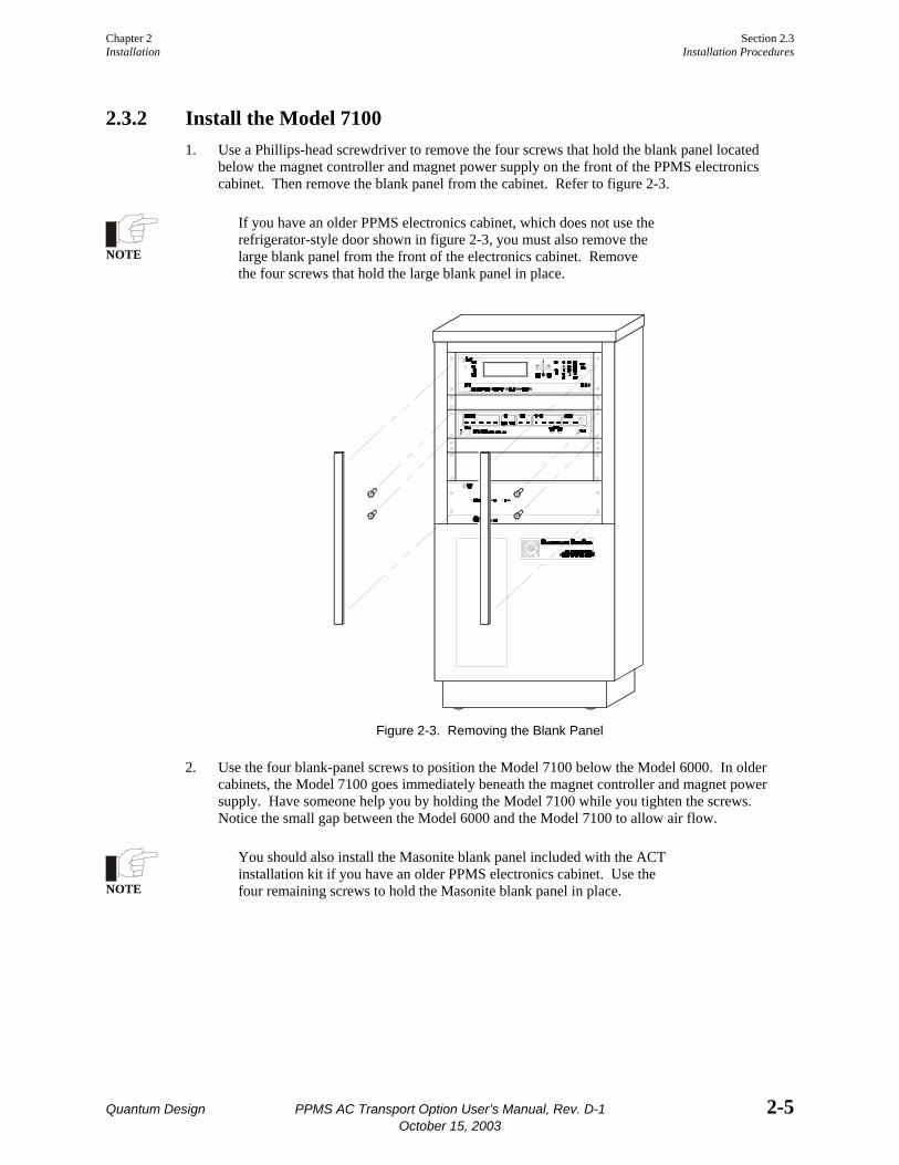
2.3.2 Install the Model 7100 1. Use a Phillips-head screwdriver to remove the four screws that hold the blank panel located
below the magnet controller and magnet power supply on the front of the PPMS electronics cabinet. Then remove the blank panel from the cabinet. Refer to figure 2-3.
NOTE
If you have an older PPMS electronics cabinet, which does not use the refrigerator-style door shown in figure 2-3, you must also remove the large blank panel from the front of the electronics cabinet. Remove the four screws that hold the large blank panel in place.
Figure 2-3. Removing the Blank Panel
2. Use the four blank-panel screws to position the Model 7100 below the Model 6000. In older cabinets, the Model 7100 goes immediately beneath the magnet controller and magnet power supply. Have someone help you by holding the Model 7100 while you tighten the screws. Notice the small gap between the Model 6000 and the Model 7100 to allow air flow.
NOTE
You should also install the Masonite blank panel included with the ACT installation kit if you have an older PPMS electronics cabinet. Use the four remaining screws to hold the Masonite blank panel in place.
Section 2.3 Chapter 2 Installation Procedures Installation
2-6 PPMS AC Transport Option User’s Manual, Rev. D-1 Quantum Design October 15, 2003
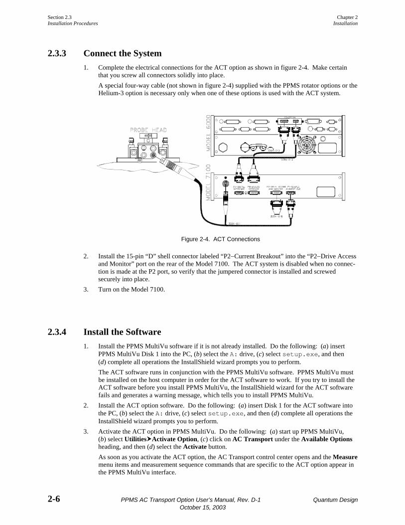
2.3.3 Connect the System 1. Complete the electrical connections for the ACT option as shown in figure 2-4. Make certain
that you screw all connectors solidly into place. A special four-way cable (not shown in figure 2-4) supplied with the PPMS rotator options or the Helium-3 option is necessary only when one of these options is used with the ACT system.
Figure 2-4. ACT Connections
2. Install the 15-pin “D” shell connector labeled “P2−Current Breakout” into the “P2−Drive Access and Monitor” port on the rear of the Model 7100. The ACT system is disabled when no connec-tion is made at the P2 port, so verify that the jumpered connector is installed and screwed securely into place.
3. Turn on the Model 7100.
2.3.4 Install the Software 1. Install the PPMS MultiVu software if it is not already installed. Do the following: (a) insert
PPMS MultiVu Disk 1 into the PC, (b) select the A: drive, (c) select setup.exe, and then (d) complete all operations the InstallShield wizard prompts you to perform. The ACT software runs in conjunction with the PPMS MultiVu software. PPMS MultiVu must be installed on the host computer in order for the ACT software to work. If you try to install the ACT software before you install PPMS MultiVu, the InstallShield wizard for the ACT software fails and generates a warning message, which tells you to install PPMS MultiVu.
2. Install the ACT option software. Do the following: (a) insert Disk 1 for the ACT software into the PC, (b) select the A: drive, (c) select setup.exe, and then (d) complete all operations the InstallShield wizard prompts you to perform.
3. Activate the ACT option in PPMS MultiVu. Do the following: (a) start up PPMS MultiVu, (b) select Utilities Activate Option, (c) click on AC Transport under the Available Options heading, and then (d) select the Activate button. As soon as you activate the ACT option, the AC Transport control center opens and the Measure menu items and measurement sequence commands that are specific to the ACT option appear in the PPMS MultiVu interface.

Quantum Design PPMS AC Transport Option User’s Manual, Rev. D-1 3-1 October 15, 2003
C H A P T E R 3
Hardware
3.1 Introduction This chapter contains the following information:
• Section 3.2 discusses the operation of the Model 7100 AC Transport Controller.
• Section 3.4 discusses the ACT cables and jumpers.
• Section 3.3 discusses the ACT option AC board.
• Section 3.5 discusses the ACT sample pucks.
3.2 Model 7100 AC Transport Controller The Model 7100 AC Transport Controller controls the operation of the ACT system. The Model 7100 includes the following components:
• Driver board with current and voltage amplifiers
• BNC connectors to monitor current and voltage across sample
• Low-noise preamp board • LEDs indicating controller status • Ports for connection to AC board
installed in Model 6000 PPMS Controller • Potentiometers for offset nulling between
parallel positive voltage leads • Ports for connection to sample
Figure 3-1. Front Panel on Model 7100 AC Transport Controller

Section 3.2 Chapter 3 Model 7100 AC Transport Controller Hardware
3-2 PPMS AC Transport Option User’s Manual, Rev. D-1 Quantum Design October 15, 2003
To excite the sample, the driver board receives and amplifies the signal from the AC board’s digital signal processor (DSP). The preamp board detects the sample signal and sends the signal back to the DSP so the DSP can process the signal. The sample signal can be very small, so the preamp board is enclosed in a :-metal casing to shield the signal from magnetic fields. The ten-turn potentiometers on the Model 7100 are also enclosed in a :-metal casing.
The Model 7100 can measure samples on channel 1 or on channel 2. The channel used for a measurement is set when the measurement is defined. The “Measure” LEDs on the front panel of the Model 7100 (figure 3-1) indicate which channel is being used. The ten-turn “Balance” potentiometers null the offset between negative and positive voltage leads prior to five-wire Hall coefficient measurements.
Two BNC outputs on the Model 7100 front panel let another instrument, such as an oscilloscope, be used to monitor the current passed through the sample and the voltage drop across the sample. The BNC outputs attenuate signals by −20 dB/decade above approximately 14 kHz. This is a property of the outputs and not of the drive electronics. The full scale of the current monitor BNC is 2 V (i.e., a reading of 2 V in the 200 mA range means that 200mA is being sent out) while the voltage monitor BNC reading must be divided by the preamp gain to obtain the readback voltage.
Caution! The Model 7100 provides as much as 2 A of current. This large current can damage samples and other equipment in the current path. Use only currents that can be safely handled by all hardware and samples in the circuit.
3.2.1 Electrical Current Operating Modes The Model 7100 can operate in either constant current mode or low-impedance mode. Figure 3-2 compares the behavior of the current in both modes.
Constant current, or high-impedance, mode is the default operating mode and the preferred mode for most applications. In constant current mode, the Model 7100 adjusts the potential drop across the current leads in order to maintain a desired current through the sample, regardless of sample resistance. The “Constant Current” LED on the Model 7100 front panel is lit when the unit operates in constant current mode.
The Model 7100 is not a perfect current source when it operates in low-impedance mode. The avail-able current decreases with the increasing potential drop across the current leads, and the actual current equals the requested current only when the sample resistance is very low compared to the Model 7100 current drive source impedance. Low-impedance mode is useful when an I-V curve might be multiple-valued in I.
Figure 3-2. The available current as a function of voltage drop across the current leads. The dashed lines indicate how the current behaves when the current setting is changed.
Chapter 3 Section 3.2 Hardware Model 7100 AC Transport Controller
Quantum Design PPMS AC Transport Option User’s Manual, Rev. D-1 3-3 October 15, 2003
If the requested current cannot be driven through the sample, the current output is shut off, the mea-surement is aborted, the “Voltage Limited” LED on the Model 7100 front panel is lit, and an error message is displayed. This can occur when the requested current is too high to be driven through the sample resistance, and often indicates that the measurement circuit is open (infinite resistance).
If the system’s thermal limit is reached, the current output is shut off, the measurement is aborted, the “Voltage Limited” LED flashes, and an error message is displayed. The LED remains flashing until the current drive amplifiers in the Model 7100 cool to an acceptable level. The built-in thermal limit protects the sample and the ACT drive electronics.
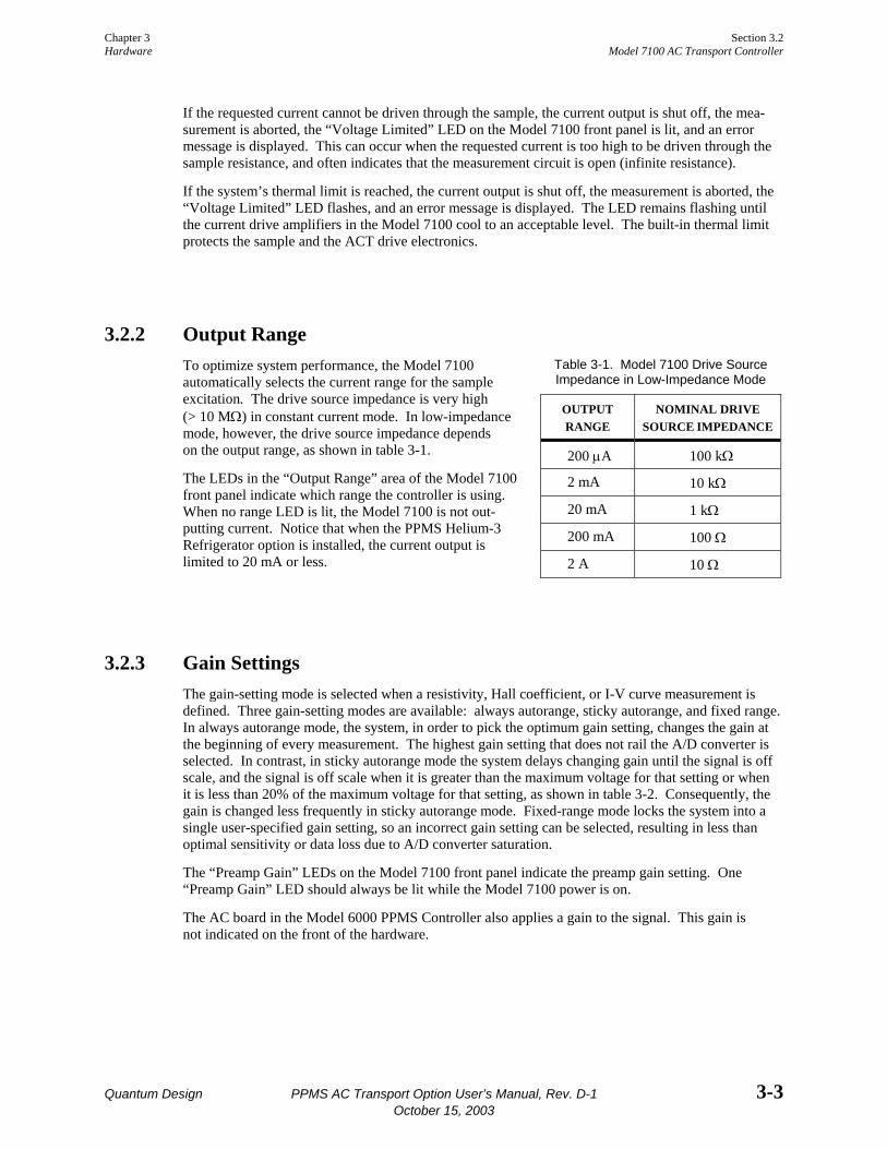
3.2.2 Output Range Table 3-1. Model 7100 Drive Source Impedance in Low-Impedance Mode
OUTPUT RANGE
NOMINAL DRIVE SOURCE IMPEDANCE
200 µA 100 kΩ
2 mA 10 kΩ
20 mA 1 kΩ
200 mA 100 Ω
To optimize system performance, the Model 7100 automatically selects the current range for the sample excitation. The drive source impedance is very high (> 10 MΩ) in constant current mode. In low-impedance mode, however, the drive source impedance depends on the output range, as shown in table 3-1.
The LEDs in the “Output Range” area of the Model 7100 front panel indicate which range the controller is using. When no range LED is lit, the Model 7100 is not out-putting current. Notice that when the PPMS Helium-3 Refrigerator option is installed, the current output is limited to 20 mA or less. 2 A 10 Ω
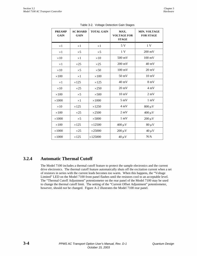
3.2.3 Gain Settings The gain-setting mode is selected when a resistivity, Hall coefficient, or I-V curve measurement is defined. Three gain-setting modes are available: always autorange, sticky autorange, and fixed range. In always autorange mode, the system, in order to pick the optimum gain setting, changes the gain at the beginning of every measurement. The highest gain setting that does not rail the A/D converter is selected. In contrast, in sticky autorange mode the system delays changing gain until the signal is off scale, and the signal is off scale when it is greater than the maximum voltage for that setting or when it is less than 20% of the maximum voltage for that setting, as shown in table 3-2. Consequently, the gain is changed less frequently in sticky autorange mode. Fixed-range mode locks the system into a single user-specified gain setting, so an incorrect gain setting can be selected, resulting in less than optimal sensitivity or data loss due to A/D converter saturation.
The “Preamp Gain” LEDs on the Model 7100 front panel indicate the preamp gain setting. One “Preamp Gain” LED should always be lit while the Model 7100 power is on.
The AC board in the Model 6000 PPMS Controller also applies a gain to the signal. This gain is not indicated on the front of the hardware.
Section 3.2 Chapter 3 Model 7100 AC Transport Controller Hardware
3-4 PPMS AC Transport Option User’s Manual, Rev. D-1 Quantum Design October 15, 2003
Table 3-2. Voltage Detection Gain Stages
PREAMP GAIN
AC BOARD GAIN
TOTAL GAIN MAX. VOLTAGE FOR
STAGE
MIN. VOLTAGE FOR STAGE
×1 ×1 ×1 5 V 1 V
×1 ×5 ×5 1 V 200 mV
×10 ×1 ×10 500 mV 100 mV
×1 ×25 ×25 200 mV 40 mV
×10 ×5 ×50 100 mV 20 mV
×100 ×1 ×100 50 mV 10 mV
×1 ×125 ×125 40 mV 8 mV
×10 ×25 ×250 20 mV 4 mV
×100 ×5 ×500 10 mV 2 mV
×1000 ×1 ×1000 5 mV 1 mV
×10 ×125 ×1250 4 mV 800 µV
×100 ×25 ×2500 2 mV 400 µV
×1000 ×5 ×5000 1 mV 200 µV
×100 ×125 ×12500 400 µV 80 µV
×1000 ×25 ×25000 200 µV 40 µV
×1000 ×125 ×125000 40 µV N/A
3.2.4 Automatic Thermal Cutoff The Model 7100 includes a thermal cutoff feature to protect the sample electronics and the current drive electronics. The thermal cutoff feature automatically shuts off the excitation current when a set of resistors in series with the current leads becomes too warm. When this happens, the “Voltage Limited” LED on the Model 7100 front panel flashes until the resistors cool to an acceptable level. The “Thermal Cutoff Adjustment” potentiometer on the rear panel of the Model 7100 may be used to change the thermal cutoff limit. The setting of the “Current Offset Adjustment” potentiometer, however, should not be changed. Figure A-2 illustrates the Model 7100 rear panel.

Chapter 3 Section 3.4 Hardware Cables and Jumpers
Quantum Design PPMS AC Transport Option User’s Manual, Rev. D-1 3-5 October 15, 2003
3.3 Model 6000 AC Board The AC board is installed in the Model 6000 PPMS Controller and is located behind the “P3−Option” port, which is the port connecting the Model 6000 to the Model 7100. The AC board includes a DSP, digital-to-analog converter (DAC), current drivers, and other control electronics that are necessary to synthesize excitation signals and process sample response signals. The DSP provides the excitation waveform and processes the sample signal.
The AC board is essentially the same board used with the AC Measurement System (ACMS) option, but with an addition to the ROMs. The AC board is specially calibrated for use with each set of ACT or ACMS hardware.
3.4 Cables and Jumpers The ACT option includes one 9-pin cable, one 15-pin cable, and one “Y” cable.
The unique “Y” cable connects the sample to the Model 7100 and is specifically designed for the extremely sensitive ACT option. The “Y” cable arrangement splits the sample signal and excitation signal into two separate shielded cables designed to help prevent sample signal distortion by the excitation signal.
Figure 3-3. ACT “Y” Connection Cable
The PPMS Horizontal Rotator option and the PPMS Helium-3 Refrigerator System option require special four-way cables to simultaneously interface with the ACT option and the Model 6000 temperature control hardware. These special cables, which replace the “Y” cable normally used with the ACT option, allow the rotator thermometer to be connected to the system bridge board or to the user bridge board in the Model 6000.
A dongle that connects to the “P2−Drive Access and Monitor” port on the rear panel of the Model 7100 is also included. It contains jumpers to complete the drive circuitry of the Model 7100, and should only be removed from the Model 7100 when access to the drive breakout is required.
Section 3.5 Chapter 3 ACT Sample Pucks Hardware
3-6 PPMS AC Transport Option User’s Manual, Rev. D-1 Quantum Design October 15, 2003
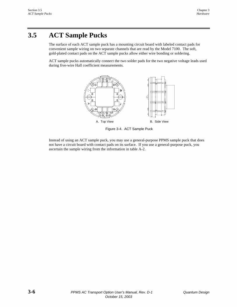
3.5 ACT Sample Pucks The surface of each ACT sample puck has a mounting circuit board with labeled contact pads for convenient sample wiring on two separate channels that are read by the Model 7100. The soft, gold-plated contact pads on the ACT sample pucks allow either wire bonding or soldering.
ACT sample pucks automatically connect the two solder pads for the two negative voltage leads used during five-wire Hall coefficient measurements.
A. Top View B. Side View
Figure 3-4. ACT Sample Puck
Instead of using an ACT sample puck, you may use a general-purpose PPMS sample puck that does not have a circuit board with contact pads on its surface. If you use a general-purpose puck, you ascertain the sample wiring from the information in table A-2.
Quantum Design PPMS AC Transport Option User’s Manual, Rev. D-1 4-1 October 15, 2003
C H A P T E R 4
Software
4.1 Introduction This chapter contains the following information:
• Section 4.2 presents an overview of the ACT software and discusses the AC Transport control center.
• Section 4.4 discusses and explains how to create ACT data files.
• Section 4.3 discusses the ACT status log.
4.2 Overview of the ACT Software The ACT option software supports resistivity, Hall coefficient, and critical current sample property measurements as well as tracing I-V curves. Measurements may be taken immediately or taken within a PPMS MultiVu sequence file. The ACT software is integrated into the PPMS MultiVu application, so you may use PPMS MultiVu commands to automate ACT operation.
Measurements performed by the ACT system are defined by the measurement parameters, such as the excitation frequency and acquisition time. Measurement results and other relevant parameters reported by the Model 6000 PPMS Controller are stored in specified ACT measurement data files.
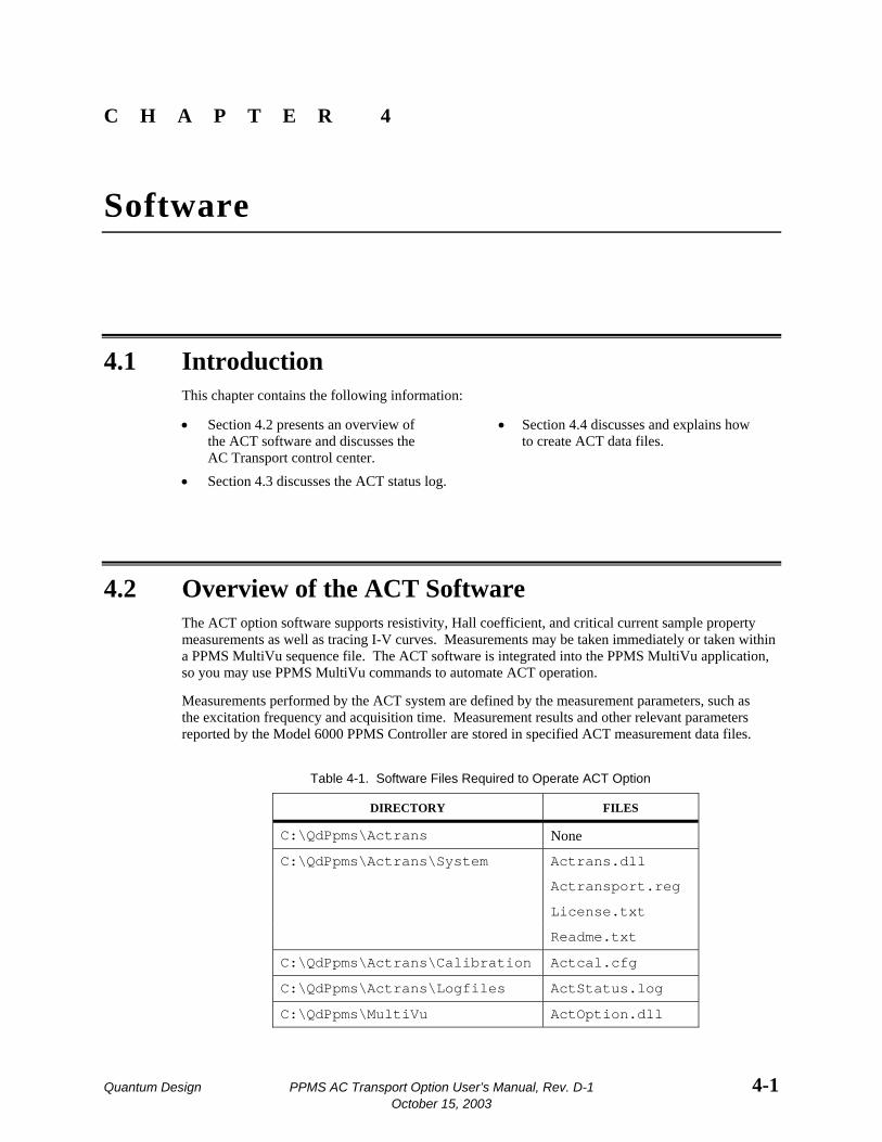
Table 4-1. Software Files Required to Operate ACT Option
DIRECTORY FILES
C:\QdPpms\Actrans None
C:\QdPpms\Actrans\System Actrans.dll
Actransport.reg
License.txt
Readme.txt
C:\QdPpms\Actrans\Calibration Actcal.cfg
C:\QdPpms\Actrans\Logfiles ActStatus.log
C:\QdPpms\MultiVu ActOption.dll
Section 4.2 Chapter 4 Overview of the ACT Software Software
4-2 PPMS AC Transport Option User’s Manual, Rev. D-1 Quantum Design October 15, 2003
The calibration file for the ACT option contains specific calibration information pertaining to the serialized AC board, ACT preamp board, and ACT driver board. During start-up, the serial numbers are shown in the Status bar in the AC Transport control center (see section 4.2.1) and should match the actual serial numbers on the system hardware.
4.2.1 AC Transport Control Center The ACT software includes a control center. The AC Transport control center opens as soon as the ACT option is activated, and does not close until the option is deactivated. The AC Transport control center makes basic system operations, such as installing samples, creating data files, and setting up and running immediate-mode measurements, more natural and convenient. The control center includes all frequently selected ACT commands. Software prompts and an easy-to-use tab format simplify data file creation. Figures 4-1 through 4-5 illustrate the six tabs in the control center.
The Status bar at the bottom of the AC Transport control center summarizes the general status of the ACT system. The Status bar indicates the progress of an on-going measurement and summarizes the results of the last measurement. Color-coded warning and error messages in the Status bar alert you to possible problems. Warning messages appear on a yellow background. Error messages appear on a red background. Appendix B lists the warning and error messages.
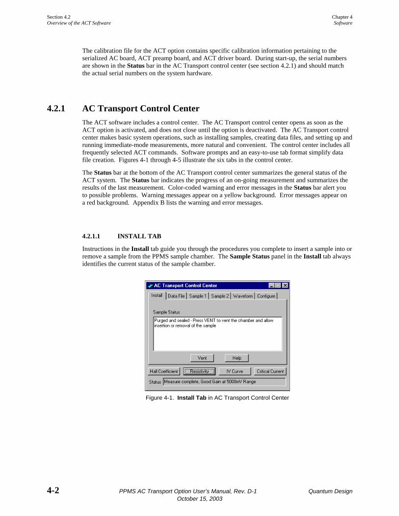
4.2.1.1 INSTALL TAB
Instructions in the Install tab guide you through the procedures you complete to insert a sample into or remove a sample from the PPMS sample chamber. The Sample Status panel in the Install tab always identifies the current status of the sample chamber.
Figure 4-1. Install Tab in AC Transport Control Center
Chapter 4 Section 4.2 Software Overview of the ACT Software
Quantum Design PPMS AC Transport Option User’s Manual, Rev. D-1 4-3 October 15, 2003
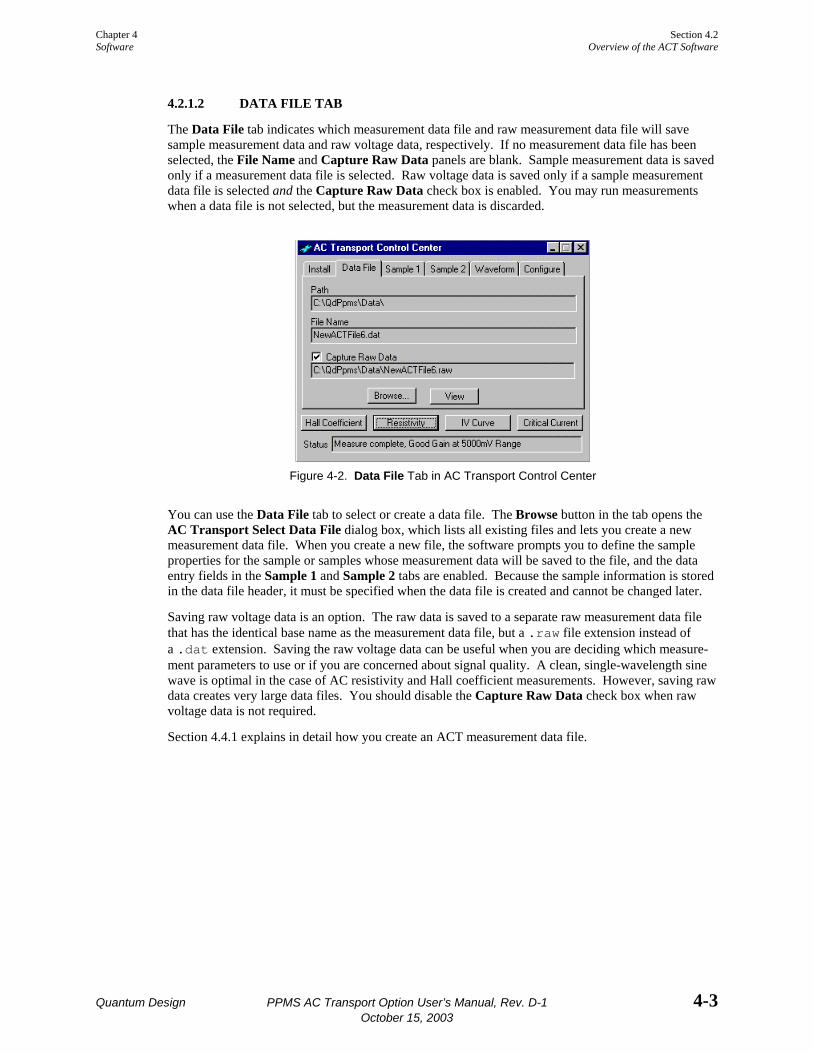
4.2.1.2 DATA FILE TAB
The Data File tab indicates which measurement data file and raw measurement data file will save sample measurement data and raw voltage data, respectively. If no measurement data file has been selected, the File Name and Capture Raw Data panels are blank. Sample measurement data is saved only if a measurement data file is selected. Raw voltage data is saved only if a sample measurement data file is selected and the Capture Raw Data check box is enabled. You may run measurements when a data file is not selected, but the measurement data is discarded.
Figure 4-2. Data File Tab in AC Transport Control Center
You can use the Data File tab to select or create a data file. The Browse button in the tab opens the AC Transport Select Data File dialog box, which lists all existing files and lets you create a new measurement data file. When you create a new file, the software prompts you to define the sample properties for the sample or samples whose measurement data will be saved to the file, and the data entry fields in the Sample 1 and Sample 2 tabs are enabled. Because the sample information is stored in the data file header, it must be specified when the data file is created and cannot be changed later.
Saving raw voltage data is an option. The raw data is saved to a separate raw measurement data file that has the identical base name as the measurement data file, but a .raw file extension instead of a .dat extension. Saving the raw voltage data can be useful when you are deciding which measure-ment parameters to use or if you are concerned about signal quality. A clean, single-wavelength sine wave is optimal in the case of AC resistivity and Hall coefficient measurements. However, saving raw data creates very large data files. You should disable the Capture Raw Data check box when raw voltage data is not required.
Section 4.4.1 explains in detail how you create an ACT measurement data file.
Section 4.2 Chapter 4 Overview of the ACT Software Software
4-4 PPMS AC Transport Option User’s Manual, Rev. D-1 Quantum Design October 15, 2003
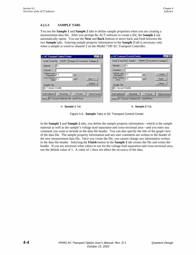
4.2.1.3 SAMPLE TABS
You use the Sample 1 and Sample 2 tabs to define sample properties when you are creating a measurement data file. After you prompt the ACT software to create a file, the Sample 1 tab automatically opens. You use the Next and Back buttons to move back and forth between the two Sample tabs. Entering sample property information in the Sample 2 tab is necessary only when a sample is wired to channel 2 on the Model 7100 AC Transport Controller.
A. Sample 1 Tab B. Sample 2 Tab
Figure 4-3. Sample Tabs in AC Transport Control Center
In the Sample 1 and Sample 2 tabs, you define the sample property information⎯which is the sample material as well as the sample’s voltage lead separation and cross-sectional area⎯and you enter any comment you want to include in the data file header. You can also specify the title of the graph view of the data file. The sample property information and any user comments are written to the header of the new measurement data file. Once you create the file, you cannot change any information written to the data file header. Selecting the Finish button in the Sample 2 tab creates the file and writes the header. If you are uncertain what values to use for the voltage lead separation and cross-sectional area, use the default value of 1. A value of 1 does not affect the accuracy of the data.

Chapter 4 Section 4.2 Software Overview of the ACT Software
Quantum Design PPMS AC Transport Option User’s Manual, Rev. D-1 4-5 October 15, 2003
4.2.1.4 WAVEFORM TAB
The Waveform tab shows a diagnostic plot of the results of the last measurement. The light blue curve in the display area indicates the ideal measurement results. The actual measured waveform is shown in black. The light blue curve is not visible if the measured waveform and ideal plot are nearly identical. Compare drawings A, C, and D in figure 4-4 below.
The plot in the Waveform tab is overwritten each time you run another measurement.
A. Sine wave indicating good signal reading. B. Flat line indicating no signal was read.
C. Very noisy signal was read. D. Distorted signal was read.
Figure 4-4. Waveform Tab in AC Transport Control Center
Section 4.2 Chapter 4 Overview of the ACT Software Software
4-6 PPMS AC Transport Option User’s Manual, Rev. D-1 Quantum Design October 15, 2003
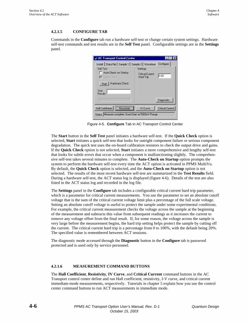
4.2.1.5 CONFIGURE TAB
Commands in the Configure tab run a hardware self-test or change certain system settings. Hardware self-test commands and test results are in the Self Test panel. Configurable settings are in the Settings panel.
Figure 4-5. Configure Tab in AC Transport Control Center
The Start button in the Self Test panel initiates a hardware self-test. If the Quick Check option is selected, Start initiates a quick self-test that looks for outright component failure or serious component degradation. The quick test uses the on-board calibration resistors to check the output drive and gains. If the Quick Check option is not selected, Start initiates a more comprehensive and lengthy self-test that looks for subtle errors that occur when a component is malfunctioning slightly. The comprehen-sive self-test takes several minutes to complete. The Auto-Check on Startup option prompts the system to perform the hardware self-test every time the ACT option is activated in PPMS MultiVu. By default, the Quick Check option is selected, and the Auto-Check on Startup option is not selected. The results of the most recent hardware self-test are summarized in the Test Results field. During a hardware self-test, the ACT status log is displayed (figure 4-6). Details of the test are also listed in the ACT status log and recorded in the log file.
The Settings panel in the Configure tab includes a configurable critical current hard trip parameter, which is a parameter for critical current measurements. You use the parameter to set an absolute cutoff voltage that is the sum of the critical current voltage limit plus a percentage of the full scale voltage. Setting an absolute cutoff voltage is useful to protect the sample under some experimental conditions. For example, the critical current measurement checks the voltage across the sample at the beginning of the measurement and subtracts this value from subsequent readings as it increases the current to remove any voltage offset from the final result. If, for some reason, the voltage across the sample is very large before the measurement begins, the hard trip setting helps protect the sample by cutting off the current. The critical current hard trip is a percentage from 0 to 100%, with the default being 20%. The specified value is remembered between ACT sessions.
The diagnostic mode accessed through the Diagnostic button in the Configure tab is password protected and is used only by service personnel.
4.2.1.6 MEASUREMENT COMMAND BUTTONS
The Hall Coefficient, Resistivity, IV Curve, and Critical Current command buttons in the AC Transport control center define and run Hall coefficient, resistivity, I-V curve, and critical current immediate-mode measurements, respectively. Tutorials in chapter 5 explain how you use the control center command buttons to run ACT measurements in immediate mode.
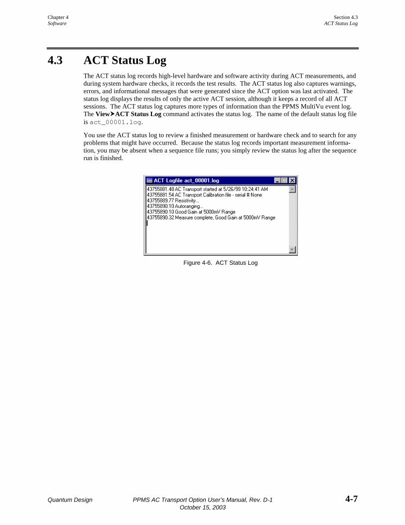
Chapter 4 Section 4.3 Software ACT Status Log
Quantum Design PPMS AC Transport Option User’s Manual, Rev. D-1 4-7 October 15, 2003
4.3 ACT Status Log The ACT status log records high-level hardware and software activity during ACT measurements, and during system hardware checks, it records the test results. The ACT status log also captures warnings, errors, and informational messages that were generated since the ACT option was last activated. The status log displays the results of only the active ACT session, although it keeps a record of all ACT sessions. The ACT status log captures more types of information than the PPMS MultiVu event log. The View ACT Status Log command activates the status log. The name of the default status log file is act_00001.log.
You use the ACT status log to review a finished measurement or hardware check and to search for any problems that might have occurred. Because the status log records important measurement informa-tion, you may be absent when a sequence file runs; you simply review the status log after the sequence run is finished.
Figure 4-6. ACT Status Log

Section 4.4 Chapter 4 ACT Data Files Software
4-8 PPMS AC Transport Option User’s Manual, Rev. D-1 Quantum Design October 15, 2003
4.4 ACT Data Files The ACT software creates measurement data files and raw measurement data files and stores ACT measurement data in these files. Measurement data files store sample measurement data for any number of measurements taken by any of the measurement types supported by the ACT option. Raw measurement data files store raw voltage data for every measurement taken while the raw file is selected. Measurement data files have a .dat file extension. Raw measurement data files have a .raw extension. Each raw measurement data file is associated with one measurement data file and uses the identical base name as the measurement data file.
Sample measurement data is saved only if a measurement data file is selected. Raw voltage data is saved only if a measurement data file is selected and the software is prompted to capture raw voltage data. Data is saved to only the selected data file or files. The Data File tab in the AC Transport control center indicates which data file or files will save measurement data (figure 4-2). If no data file has been selected, the File Name and Capture Raw Data panels are blank.
The data file header contains file and sample property information that is defined when the data file is created. Information written to the data file header cannot be subsequently changed in PPMS MultiVu. The file information that can be written to the header consists of the title assigned to the graph view of the data file. The sample property information consists of the sample’s material and voltage lead separation and the cross-sectional area through which the current passes. All information written to the header appears in the INFO declarations in the header.
It is extremely important that you define the correct voltage lead separation ( l ) and cross-sectional area for the current (A) when you create a data file. The system uses whatever values are specified for these two parameters in order to calculate the sample resistivity and the Hall coefficient. If you are concerned about entering incorrect values into the data file header, use a value of 1. The results written to the data file header are then resistance and Hall resistance, rather than resistivity and Hall coefficient, because these values are calculated by multiplying the resistance by a factor of
( )Αl .
The ACT software automatically records the following data for every measurement: time, PPMS status code, system temperature, magnetic field, sample position (or angle), sample chamber pressure, mappable channel 23 (for a user thermometer), and relevant values corresponding to the measurement, such as excitation amplitude, frequency, Hall coefficient, resistivity, and so on.
Subsequently changing samples without changing data files can destroy the validity of the data in the file. Therefore, you are encouraged to use the automated sample installation routine that is activated in the Install tab of the AC Transport control center. The automated installation routine prompts you for new data file(s) and new sample information after you install a new sample.
One data file can store data from any number of the four measurement types supported by the ACT option. However, reading a file containing data from multiple types of measurements can be difficult. The Physical Property Measurement System: PPMS MultiVu Application User’s Manual discusses the data file format in detail.
Data files may be viewed in several different formats. The Physical Property Measurement System: PPMS MultiVu Application User’s Manual discusses the data-viewing formats in detail.

Chapter 4 Section 4.4 Software ACT Data Files
Quantum Design PPMS AC Transport Option User’s Manual, Rev. D-1 4-9 October 15, 2003
4.4.1 Creating an ACT Measurement Data File 1. Select the Data File tab in the AC Transport control center. Figure 4-2 illustrates the tab.
The File Name and Capture Raw Data panels in the Data File tab indicate which data files are selected to save measurement data. If no data file has been selected, these two panels are blank. Measurement data is saved only if a measurement data file is selected.
2. Select the Browse button. The AC Transport Select Data File dialog box opens. The dialog box lists all existing data files.
3. Select the drive and directory where the new data files will reside, if necessary. The default directory to which PPMS MultiVu writes data files is C:\QdPpms\Data.
4. Use the File name text box in the AC Transport Select Data File dialog box to enter the name of the new data file. If you enter the name of an existing data file or double-click on an existing file, that file will be overwritten.
5. Select Open. A pop-up message tells you that you must define the sample properties in order to create the data file.
6. Select OK in the pop-up message. The Sample 1 tab in the AC Transport control center opens, and all data entry fields in the tab are enabled. Figure 4-3 illustrates the Sample 1 tab.
7. Enter the sample property information in the appropriate tab or tabs. Enter information in the Sample 1 tab if the sample is wired to channel 1 on the Model 7100 AC Transport Controller. Enter information in the Sample 2 tab if the sample is wired to channel 2. Use the Next and Back buttons to move back and forth between the two Sample tabs. (a) Use the Material text box to define the sample material. The sample material information
is saved in the data file header, but is not used to calculate measurement values. (b) Use the Comment text box to enter any comment you want to include in the data file
header. (c) Use the Voltage Lead Separation text box to define the sample’s voltage lead separation.
If you are uncertain what the length of the voltage lead separation is, use the default value of 1 cm.
(d) Use the Cross Section Area text box to define the cross-sectional area, in the sample, through which the current passes. If you are uncertain what the cross-sectional area is, use the default value of 1 cm2.
NOTE
Always use the default value of 1 if you do not know the actual value of the sample’s voltage lead separation or cross-sectional area. A value of 1 lets the calculated values reflect numbers unadjusted for sample geometry and thus allows easy interpretation of resistivity and Hall coefficient values if sample information is unavailable.
Caution! Defining the correct voltage lead separation and cross-sectional area is extremely important because the system uses these values to calculate the sample resistivity and the Hall coefficient. Once you create the data file, you cannot use the software to redefine any information that was written to the data file header.
(e) Use the Datafile Title text box to specify a title for the graph view of the data file, if you like. Specifying a title for the graph view is not mandatory.
(f) Select Next to open the Sample 2 tab, or select Back to open the Sample 1 tab.

Section 4.4 Chapter 4 ACT Data Files Software
4-10 PPMS AC Transport Option User’s Manual, Rev. D-1 Quantum Design October 15, 2003
(g) Select Finish in the Sample 2 tab when you have finished defining sample property information and are ready to create the data file. The Data File tab appears again and displays the name of the data file you have created. The data entry fields in the Sample tabs are disabled. You cannot change any of the information written to the data file header.
8. Enable the Capture Raw Data check box if you want to save the raw voltage data to a raw measurement data file. Saving raw voltage data can be useful, but requires a significant amount of disk space. The raw measurement data file will have the identical base name as the measure-ment data file.
Once you select a data file or data files, all subsequent measurement data is saved to those files until you use the ACT software to either select new files or no file.
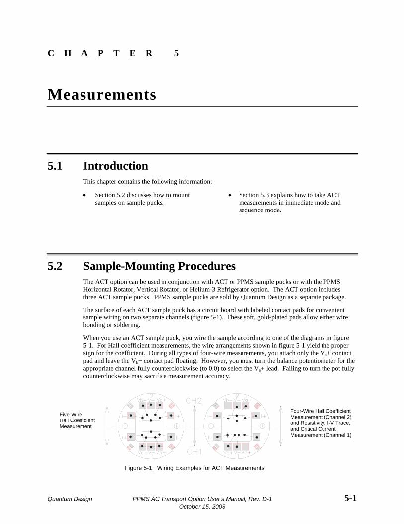
Quantum Design PPMS AC Transport Option User’s Manual, Rev. D-1 5-1 October 15, 2003
C H A P T E R 5
Measurements
5.1 Introduction This chapter contains the following information:
• Section 5.2 discusses how to mount samples on sample pucks.
• Section 5.3 explains how to take ACT measurements in immediate mode and sequence mode.
5.2 Sample-Mounting Procedures The ACT option can be used in conjunction with ACT or PPMS sample pucks or with the PPMS Horizontal Rotator, Vertical Rotator, or Helium-3 Refrigerator option. The ACT option includes three ACT sample pucks. PPMS sample pucks are sold by Quantum Design as a separate package.
The surface of each ACT sample puck has a circuit board with labeled contact pads for convenient sample wiring on two separate channels (figure 5-1). These soft, gold-plated pads allow either wire bonding or soldering.
When you use an ACT sample puck, you wire the sample according to one of the diagrams in figure 5-1. For Hall coefficient measurements, the wire arrangements shown in figure 5-1 yield the proper sign for the coefficient. During all types of four-wire measurements, you attach only the Va+ contact pad and leave the Vb+ contact pad floating. However, you must turn the balance potentiometer for the appropriate channel fully counterclockwise (to 0.0) to select the Va+ lead. Failing to turn the pot fully counterclockwise may sacrifice measurement accuracy.
Five-Wire Hall Coefficient Measurement
Four-Wire Hall Coefficient Measurement (Channel 2) and Resistivity, I-V Trace, and Critical Current Measurement (Channel 1)
Figure 5-1. Wiring Examples for ACT Measurements

Section 5.2 Chapter 5 Sample-Mounting Procedures Measurements
5-2 PPMS AC Transport Option User’s Manual, Rev. D-1 Quantum Design October 15, 2003
Section 1.3.1 also discusses techniques for connecting sample leads for four-wire resistivity measure-ments. Sections 1.3.2 and 1.3.2.1 discuss techniques for connecting leads for four-wire and five-wire Hall coefficient measurements. Chapter 6 includes important information about using the ACT system with the Helium-3 Refrigerator System option. Chapter 7 includes important information about using the ACT system with the Horizontal Rotator option.
Appendix A includes a table of solder pad descriptions for the PPMS sample pucks. When you use PPMS sample pucks, make certain that, for five-wire measurements, you tie together the V− leads for the appropriate channel. You should also refer to the appropriate option manual for information about securing the sample to the sample holder, and for further sample-mounting information.
Due to the high sensitivity of the ACT option, it is important to use the option to perform only true four-wire and five-wire measurements. Keep this in mind when you are attaching leads to the sample. Even with true four-wire and five-wire measurements, accuracy can be compromised if contact resistance is too high or grossly mismatched.
Once the sample is properly mounted on the sample holder, remember to write down the sample’s voltage lead separation and current cross-sectional area. This information is saved in the header of any new data file you create to store the sample measurement data.
Chapter 5 Section 5.3 Measurements ACT Measurements
Quantum Design PPMS AC Transport Option User’s Manual, Rev. D-1 5-3 October 15, 2003
5.3 ACT Measurements
NOTE
ACT measurements can be taken only if the ACT connector cables are plugged into the correct ports and the ACT option is activated in PPMS MultiVu. Refer to chapter 2 to install and activate the ACT option.
ACT measurements may run in immediate mode or sequence mode. AC Transport control center commands and PPMS MultiVu Measure menu commands execute measurements immediately, but each control center or menu command must be selected manually. ACT measurement sequence commands included in a PPMS MultiVu sequence file are executed automatically when they are read while the sequence runs. Any number of measurement sequence commands may be included in a sequence file.
Data from immediate-mode measurements is saved only if an ACT measurement data file is selected to store the data, and once the measurement is complete, the Save button in the measurement dialog box is selected, prompting the system to save the data to the specified file. Measurement and selected system data read during sequence mode measurements is automatically saved to the specified data file. By default, when an ACT sequence measurement runs, the general system status, system temperature, magnetic field, sample position, and the reading from mappable channel 23 are saved to the data file.
An immediate-mode measurement can measure only one sample on the sample puck, although you may select which sample you want to measure. A sequence mode measurement command can instruct the system to measure both samples. The system measures sample 1, then it measures sample 2.
The immediate-mode measurement dialog boxes show the results from the last measurement of that same type (see figure 5-2, for example). The sequence mode measurement dialog boxes do not show measurement results, but you can use them to select which system data items you want to save to the specified ACT measurement data file (see figure 5-8).
NOTE
You are encouraged to use the AC Transport control center to perform all normal system operations. The automated routines in the control center help ensure that you complete the necessary procedures when you install new samples and create data files. The examples of immediate-mode measurements in this chapter illustrate use of the control center.
5.3.1 Taking Resistivity Measurements in Immediate Mode
5.3.1.1 PREPARE FOR THE MEASUREMENT
1. Mount the sample on a sample puck, and connect the sample leads so that you can perform a four-wire resistivity measurement. Refer to section 5.2. A thin copper sample is also provided for demonstrating the Hall effect. See Appendix C for more details.
2. Insert the sample into the sample chamber. Select the Install tab in the AC Transport control center, and then follow the software prompts.
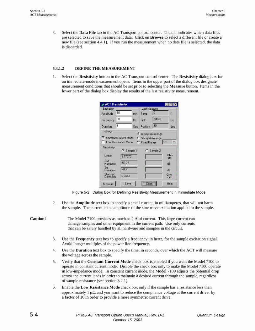
Section 5.3 Chapter 5 ACT Measurements Measurements
5-4 PPMS AC Transport Option User’s Manual, Rev. D-1 Quantum Design October 15, 2003
3. Select the Data File tab in the AC Transport control center. The tab indicates which data files are selected to save the measurement data. Click on Browse to select a different file or create a new file (see section 4.4.1). If you run the measurement when no data file is selected, the data is discarded.
5.3.1.2 DEFINE THE MEASUREMENT
1. Select the Resistivity button in the AC Transport control center. The Resistivity dialog box for an immediate-mode measurement opens. Items in the upper part of the dialog box designate measurement conditions that should be set prior to selecting the Measure button. Items in the lower part of the dialog box display the results of the last resistivity measurement.
Figure 5-2. Dialog Box for Defining Resistivity Measurement in Immediate Mode
2. Use the Amplitude text box to specify a small current, in milliamperes, that will not harm the sample. The current is the amplitude of the sine wave excitation applied to the sample.
Caution! The Model 7100 provides as much as 2 A of current. This large current can damage samples and other equipment in the current path. Use only currents that can be safely handled by all hardware and samples in the circuit.
3. Use the Frequency text box to specify a frequency, in hertz, for the sample excitation signal. Avoid integer multiples of the power line frequency.
4. Use the Duration text box to specify the time, in seconds, over which the ACT will measure the voltage across the sample.
5. Verify that the Constant Current Mode check box is enabled if you want the Model 7100 to operate in constant current mode. Disable the check box only to make the Model 7100 operate in low-impedance mode. In constant current mode, the Model 7100 adjusts the potential drop across the current leads in order to maintain a desired current through the sample, regardless of sample resistance (see section 3.2.1).
6. Enable the Low Resistance Mode check box only if the sample has a resistance less than approximately 1 µΩ and you want to reduce the compliance voltage at the current driver by a factor of 10 in order to provide a more symmetric current drive.

Chapter 5 Section 5.3 Measurements ACT Measurements
Quantum Design PPMS AC Transport Option User’s Manual, Rev. D-1 5-5 October 15, 2003
7. Select the gain setting used for voltage detection. Always Autorange instructs the system to change the gain setting at the beginning of every measurement so that the optimum setting is selected. Sticky Autorange prevents the system from changing gains until absolutely necessary. Fixed Range restricts the system to the use of a single user-specified gain setting.
8. Select the sample⎯Sample 1 or Sample 2⎯you want to measure.
5.3.1.3 RUN THE MEASUREMENT
1. Select the Measure button. The measurement begins. The Measure button now reads Cancel. You select Cancel to abort the measurement. To measure resistivity, the designated alternating current is driven through the appropriate channel for the specified duration. The Model 7100 preamp board amplifies the detected voltage signal before it is sampled by the digital signal processor on the AC board and analyzed by the software. The sample resistivity is calculated with equation 1-1. The Status panel at the bottom of the AC Transport control center indicates the status of the on-going measurement. The system temperature, magnetic field, and sample position are measured at the beginning and end of the resistivity measurement, and their average values are reported. As soon as the measurement is complete, the Waveform tab in the control center opens and displays a diagnostic plot of the measurement. The Status panel in the control center summa-rizes the measurement results. The Resistivity dialog box displays the results from the last resistivity measurement as well as the average temperature, magnetic field, and sample position used during the measurement.
2. Examine the diagnostic plot of the measurement in the Waveform tab. This plot shows you whether the sample was read and roughly indicates how effective the measurement was.
3. Select the Save button if you want to save the results of the measurement to the specified data file or files. You must select Save in order to save the data.
5.3.2 Taking Five-Wire Hall Measurements in Immediate Mode
5.3.2.1 PREPARE FOR THE MEASUREMENT
1. Mount the sample on a sample puck, and connect the sample leads so that you can perform a five-wire Hall coefficient measurement. Refer to section 5.2. A thin copper sample is provided for demonstrating the Hall effect, see Appendix C for more details.
2. Insert the sample into the sample chamber. Select the Install tab in the AC Transport control center, and then follow the software prompts.
3. Select the Data File tab in the AC Transport control center. The tab indicates which data files are selected to save the measurement data. Click on Browse to select a different file or create a new file (see section 4.4.1). If you run the measurement when no data file is selected, the data is discarded.

Section 5.3 Chapter 5 ACT Measurements Measurements
5-6 PPMS AC Transport Option User’s Manual, Rev. D-1 Quantum Design October 15, 2003
5.3.2.2 NULL THE OFFSET VOLTAGE
Prior to performing any five-wire Hall coefficient measurement, you null the offset between the nega-tive and positive voltage leads. You use the “Balance” potentiometers on the front panel of the Model 7100 AC Transport Controller to select a voltage that is between the two positive voltage leads. Complete the following steps:
1. Set the magnetic field to zero, and wait for the system to stabilize at zero field. 2. Select Measure Balance Meter. The Balance Meter dialog box opens (figure 5-3). 3. Select the sample you will measure. 4. Select the resolution, if necessary. In most cases, the Auto resolution is sufficient.
Figure 5-3. Balance Meter Dialog Box
5. Select a drive current. You should specify the largest possible drive current that will not rail the electronics or destroy the sample. A large drive current produces a large signal, so it is easier to zero the signal. Instead of selecting a very large drive current, you can alternatively select the drive current that is closest to the measurement current.
6. Select Start. 7. Turn the “Balance” potentiometer for the appropriate channel until the offset is as close to zero as
possible. The “Balance” pots are on the front panel of the Model 7100. Watch the display area at the bottom of the Balance Meter dialog box. Notice that there is a delay between when you adjust the pot and when the offset is indicated in the Balance Meter dialog box, so turn the pot slowly when the offset approaches zero.
8. Lock the “Balance” potentiometer in place once you have balanced the positive voltage leads as precisely as possible. Simply press the tab on top of the knob clockwise.
5.3.2.3 DEFINE THE MEASUREMENT
1. Set the appropriate magnetic field for the measurement. You can continue defining the mea-surement, but should not run the measurement until the field has stabilized.
2. Select the Hall Coefficient button in the AC Transport control center. The Hall Coefficient dialog box for an immediate-mode measurement opens. Items in the upper part of the dialog box designate measurement conditions that should be set prior to selecting the Measure button. Items in the lower part of the dialog display the results of the last Hall coefficient measurement.
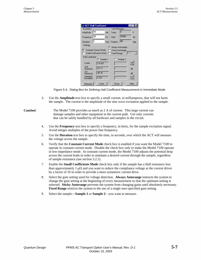
Chapter 5 Section 5.3 Measurements ACT Measurements
Quantum Design PPMS AC Transport Option User’s Manual, Rev. D-1 5-7 October 15, 2003
Figure 5-4. Dialog Box for Defining Hall Coefficient Measurement in Immediate Mode
3. Use the Amplitude text box to specify a small current, in milliamperes, that will not harm the sample. The current is the amplitude of the sine wave excitation applied to the sample.
Caution! The Model 7100 provides as much as 2 A of current. This large current can damage samples and other equipment in the current path. Use only currents that can be safely handled by all hardware and samples in the circuit.
4. Use the Frequency text box to specify a frequency, in hertz, for the sample excitation signal. Avoid integer multiples of the power line frequency.
5. Use the Duration text box to specify the time, in seconds, over which the ACT will measure the voltage across the sample.
6. Verify that the Constant Current Mode check box is enabled if you want the Model 7100 to operate in constant current mode. Disable the check box only to make the Model 7100 operate in low-impedance mode. In constant current mode, the Model 7100 adjusts the potential drop across the current leads in order to maintain a desired current through the sample, regardless of sample resistance (see section 3.2.1).
7. Enable the Small Coefficients Mode check box only if the sample has a Hall resistance less than approximately 1 µΩ and you want to reduce the compliance voltage at the current driver by a factor of 10 in order to provide a more symmetric current drive.
8. Select the gain setting used for voltage detection. Always Autorange instructs the system to change the gain setting at the beginning of every measurement so that the optimum setting is selected. Sticky Autorange prevents the system from changing gains until absolutely necessary. Fixed Range restricts the system to the use of a single user-specified gain setting.
9. Select the sample⎯Sample 1 or Sample 2⎯you want to measure.
Section 5.3 Chapter 5 ACT Measurements Measurements
5-8 PPMS AC Transport Option User’s Manual, Rev. D-1 Quantum Design October 15, 2003
5.3.2.4 RUN THE MEASUREMENT
1. Select the Measure button. The measurement begins. The Measure button now reads Cancel. You select Cancel to abort the measurement. To measure the Hall coefficient, the designated alternating current is driven through the appro-priate channel for the specified duration. The Model 7100 preamp board amplifies the detected Hall voltage before it is sampled by the digital signal processor on the AC board and analyzed by the software. The Hall coefficient is calculated with equation 1-3. The Status panel at the bottom of the AC Transport control center indicates the status of the on-going measurement. The system temperature, magnetic field, and sample position are measured at the beginning and end of the resistivity measurement, and their average values are reported. As soon as the measurement is complete, the Waveform tab in the control center opens and displays a diagnostic plot of the measurement. The Status panel in the control center summa-rizes the measurement results. The Hall Coefficient dialog box displays the results from the last Hall coefficient measurement as well as the average temperature, magnetic field, and sample position used during the measurement.
2. Examine the diagnostic plot of the measurement in the Waveform tab. This plot shows you whether the sample was read and roughly indicates how effective the measurement was.
3. Select the Save button if you want to save the results of the measurement to the specified data file or files. You must select Save in order to save the data.
5.3.3 Taking I-V Curve Measurements in Immediate Mode
5.3.3.1 PREPARE FOR THE MEASUREMENT
1. Mount the sample on a sample puck, and connect the sample leads so that you can perform a four-wire resistivity measurement. Refer to section 5.2.
2. Insert the sample into the sample chamber. Select the Install tab in the AC Transport control center, and then follow the software prompts.
3. Select the Data File tab in the AC Transport control center. The tab indicates which data files are selected to save the measurement data. Click on Browse to select a different file or create a new file (see section 4.4.1). If you run the measurement when no data file is selected, the data is discarded.
5.3.3.2 DEFINE THE MEASUREMENT
1. Select the IV Curve button in the AC Transport control center. The I-V Curve dialog box for an immediate-mode measurement opens.
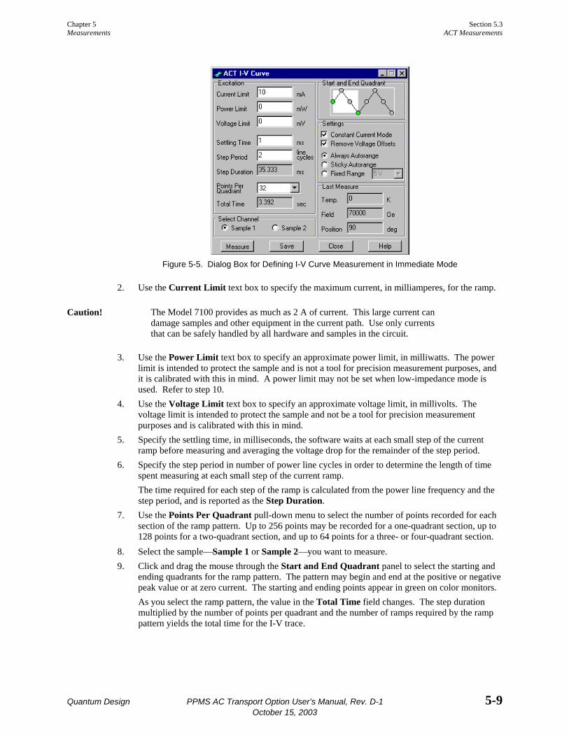
Chapter 5 Section 5.3 Measurements ACT Measurements
Quantum Design PPMS AC Transport Option User’s Manual, Rev. D-1 5-9 October 15, 2003
Figure 5-5. Dialog Box for Defining I-V Curve Measurement in Immediate Mode
2. Use the Current Limit text box to specify the maximum current, in milliamperes, for the ramp.
Caution! The Model 7100 provides as much as 2 A of current. This large current can damage samples and other equipment in the current path. Use only currents that can be safely handled by all hardware and samples in the circuit.
3. Use the Power Limit text box to specify an approximate power limit, in milliwatts. The power limit is intended to protect the sample and is not a tool for precision measurement purposes, and it is calibrated with this in mind. A power limit may not be set when low-impedance mode is used. Refer to step 10.
4. Use the Voltage Limit text box to specify an approximate voltage limit, in millivolts. The voltage limit is intended to protect the sample and not be a tool for precision measurement purposes and is calibrated with this in mind.
5. Specify the settling time, in milliseconds, the software waits at each small step of the current ramp before measuring and averaging the voltage drop for the remainder of the step period.
6. Specify the step period in number of power line cycles in order to determine the length of time spent measuring at each small step of the current ramp. The time required for each step of the ramp is calculated from the power line frequency and the step period, and is reported as the Step Duration.
7. Use the Points Per Quadrant pull-down menu to select the number of points recorded for each section of the ramp pattern. Up to 256 points may be recorded for a one-quadrant section, up to 128 points for a two-quadrant section, and up to 64 points for a three- or four-quadrant section.
8. Select the sample⎯Sample 1 or Sample 2⎯you want to measure. 9. Click and drag the mouse through the Start and End Quadrant panel to select the starting and
ending quadrants for the ramp pattern. The pattern may begin and end at the positive or negative peak value or at zero current. The starting and ending points appear in green on color monitors. As you select the ramp pattern, the value in the Total Time field changes. The step duration multiplied by the number of points per quadrant and the number of ramps required by the ramp pattern yields the total time for the I-V trace.

Section 5.3 Chapter 5 ACT Measurements Measurements
5-10 PPMS AC Transport Option User’s Manual, Rev. D-1 Quantum Design October 15, 2003
10. Verify that the Constant Current Mode check box is enabled if you want the Model 7100 to operate in constant current mode. Disable the check box only to make the Model 7100 operate in low-impedance mode. In constant current mode, the Model 7100 adjusts the potential drop across the current leads in order to maintain a desired current through the sample, regardless of sample resistance (see section 3.2.1).
11. Verify that the Remove Voltage Offsets check box is enabled if you want the system to measure the input voltage before any current is applied to the sample, and then subtract this baseline voltage off of all subsequent readings for the I-V trace.
12. Select the gain setting used for voltage detection. Always Autorange instructs the system to change the gain setting at the beginning of every measurement so that the optimum setting is selected. Sticky Autorange prevents the system from changing gains until absolutely necessary. Fixed Range restricts the system to the use of a single user-specified gain setting.
5.3.3.3 RUN THE MEASUREMENT
1. Select the Measure button. The measurement begins. The Measure button now reads Cancel. You select Cancel to abort the measurement. The Status panel at the bottom of the AC Transport control center indicates the status of the on-going measurement and summarizes the results when the measurement is complete. The Waveform tab in the control center opens as soon as the measurement is complete, and displays a diagnostic plot of the measurement. The I-V Curve dialog box displays the average tempera-ture, magnetic field, and sample position used during the last I-V trace. The result of one I-V trace is an entire set of data. Unlike most measurements with the PPMS, the time stamp accompanying each data point is not the exact time of the measurement, but is an approximation of the measurement time according to the measurement parameters.
2. Examine the diagnostic plot of the measurement in the Waveform tab. This plot shows you the results of the I-V curve trace.
3. Select the Save button if you want to save the results of the measurement to the specified data file or files. You must select Save in order to save the data.
5.3.4 Taking Critical Current Measurements in Immediate Mode
Caution! The ACT critical current measurement automatically adjusts the critical voltage for voltage offsets seen at the beginning of each measurement. For this reason, it is important to use the critical current feature with only superconducting samples.
5.3.4.1 PREPARE FOR THE MEASUREMENT
1. Mount the sample on a sample puck, and connect the sample leads so that you can perform a four-wire resistivity measurement. Refer to section 5.2.
2. Insert the sample into the sample chamber. Select the Install tab in the AC Transport control center, and then follow the software prompts.
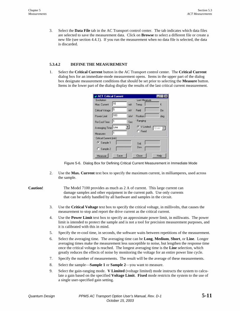
Chapter 5 Section 5.3 Measurements ACT Measurements
Quantum Design PPMS AC Transport Option User’s Manual, Rev. D-1 5-11 October 15, 2003
3. Select the Data File tab in the AC Transport control center. The tab indicates which data files are selected to save the measurement data. Click on Browse to select a different file or create a new file (see section 4.4.1). If you run the measurement when no data file is selected, the data is discarded.
5.3.4.2 DEFINE THE MEASUREMENT
1. Select the Critical Current button in the AC Transport control center. The Critical Current dialog box for an immediate-mode measurement opens. Items in the upper part of the dialog box designate measurement conditions that should be set prior to selecting the Measure button. Items in the lower part of the dialog display the results of the last critical current measurement.
Figure 5-6. Dialog Box for Defining Critical Current Measurement in Immediate Mode
2. Use the Max. Current text box to specify the maximum current, in milliamperes, used across the sample.
Caution! The Model 7100 provides as much as 2 A of current. This large current can damage samples and other equipment in the current path. Use only currents that can be safely handled by all hardware and samples in the circuit.
3. Use the Critical Voltage text box to specify the critical voltage, in millivolts, that causes the measurement to stop and report the drive current as the critical current.
4. Use the Power Limit text box to specify an approximate power limit, in milliwatts. The power limit is intended to protect the sample and is not a tool for precision measurement purposes, and it is calibrated with this in mind.
5. Specify the re-cool time, in seconds, the software waits between repetitions of the measurement. 6. Select the averaging time. The averaging time can be Long, Medium, Short, or Line. Longer
averaging times make the measurement less susceptible to noise, but lengthen the response time once the critical voltage is reached. The longest averaging time is the Line selection, which greatly reduces the effects of noise by monitoring the voltage for an entire power line cycle.
7. Specify the number of measurements. The result will be the average of these measurements. 8. Select the sample⎯Sample 1 or Sample 2⎯you want to measure. 9. Select the gain-ranging mode. V Limited (voltage limited) mode instructs the system to calcu-
late a gain based on the specified Voltage Limit. Fixed mode restricts the system to the use of a single user-specified gain setting.
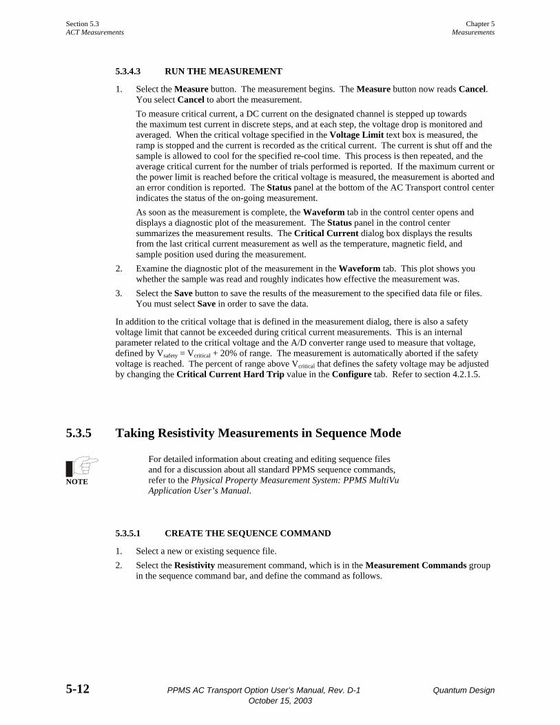
Section 5.3 Chapter 5 ACT Measurements Measurements
5-12 PPMS AC Transport Option User’s Manual, Rev. D-1 Quantum Design October 15, 2003
5.3.4.3 RUN THE MEASUREMENT
1. Select the Measure button. The measurement begins. The Measure button now reads Cancel. You select Cancel to abort the measurement. To measure critical current, a DC current on the designated channel is stepped up towards the maximum test current in discrete steps, and at each step, the voltage drop is monitored and averaged. When the critical voltage specified in the Voltage Limit text box is measured, the ramp is stopped and the current is recorded as the critical current. The current is shut off and the sample is allowed to cool for the specified re-cool time. This process is then repeated, and the average critical current for the number of trials performed is reported. If the maximum current or the power limit is reached before the critical voltage is measured, the measurement is aborted and an error condition is reported. The Status panel at the bottom of the AC Transport control center indicates the status of the on-going measurement. As soon as the measurement is complete, the Waveform tab in the control center opens and displays a diagnostic plot of the measurement. The Status panel in the control center summarizes the measurement results. The Critical Current dialog box displays the results from the last critical current measurement as well as the temperature, magnetic field, and sample position used during the measurement.
2. Examine the diagnostic plot of the measurement in the Waveform tab. This plot shows you whether the sample was read and roughly indicates how effective the measurement was.
3. Select the Save button to save the results of the measurement to the specified data file or files. You must select Save in order to save the data.
In addition to the critical voltage that is defined in the measurement dialog, there is also a safety voltage limit that cannot be exceeded during critical current measurements. This is an internal parameter related to the critical voltage and the A/D converter range used to measure that voltage, defined by Vsafety = Vcritical + 20% of range. The measurement is automatically aborted if the safety voltage is reached. The percent of range above Vcritical that defines the safety voltage may be adjusted by changing the Critical Current Hard Trip value in the Configure tab. Refer to section 4.2.1.5.
5.3.5 Taking Resistivity Measurements in Sequence Mode
NOTE
For detailed information about creating and editing sequence files and for a discussion about all standard PPMS sequence commands, refer to the Physical Property Measurement System: PPMS MultiVu Application User’s Manual.
5.3.5.1 CREATE THE SEQUENCE COMMAND
1. Select a new or existing sequence file. 2. Select the Resistivity measurement command, which is in the Measurement Commands group
in the sequence command bar, and define the command as follows.
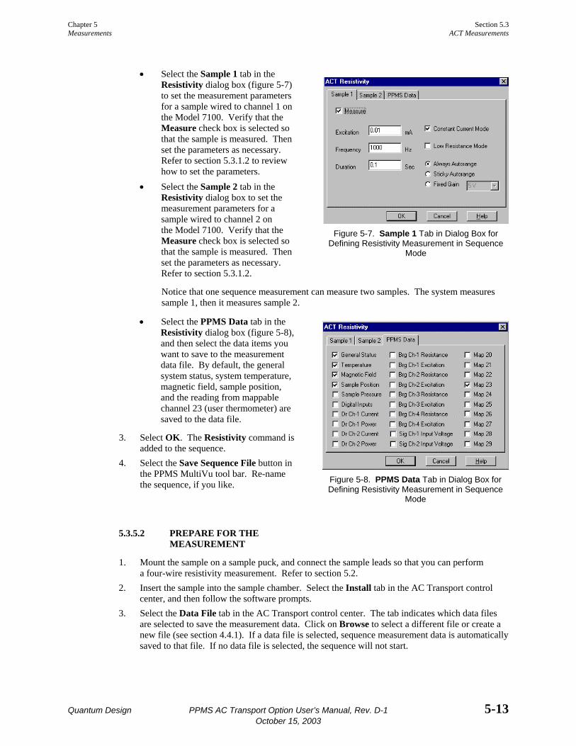
Chapter 5 Section 5.3 Measurements ACT Measurements
Quantum Design PPMS AC Transport Option User’s Manual, Rev. D-1 5-13 October 15, 2003
• Select the Sample 1 tab in the Resistivity dialog box (figure 5-7) to set the measurement parameters for a sample wired to channel 1 on the Model 7100. Verify that the Measure check box is selected so that the sample is measured. Then set the parameters as necessary. Refer to section 5.3.1.2 to review how to set the parameters.
• Select the Sample 2 tab in the Resistivity dialog box to set the measurement parameters for a sample wired to channel 2 on the Model 7100. Verify that the Measure check box is selected so that the sample is measured. Then set the parameters as necessary. Refer to section 5.3.1.2.
Notice that one sequence measurement can measure two samples. The system measures sample 1, then it measures sample 2.
• Select the PPMS Data tab in the Resistivity dialog box (figure 5-8), and then select the data items you want to save to the measurement data file. By default, the general system status, system temperature, magnetic field, sample position, and the reading from mappable channel 23 (user thermometer) are saved to the data file.
3. Select OK. The Resistivity command is added to the sequence.
4. Select the Save Sequence File button in the PPMS MultiVu tool bar. Re-name the sequence, if you like.
5.3.5.2 PREPARE FOR THE MEASUREMENT
1. Mount the sample on a sample puck, and connect the sample leads so that you can perform a four-wire resistivity measurement. Refer to section 5.2.
2. Insert the sample into the sample chamber. Select the Install tab in the AC Transport control center, and then follow the software prompts.
3. Select the Data File tab in the AC Transport control center. The tab indicates which data files are selected to save the measurement data. Click on Browse to select a different file or create a new file (see section 4.4.1). If a data file is selected, sequence measurement data is automatically saved to that file. If no data file is selected, the sequence will not start.
Figure 5-7. Sample 1 Tab in Dialog Box for
Defining Resistivity Measurement in Sequence Mode
Figure 5-8. PPMS Data Tab in Dialog Box for Defining Resistivity Measurement in Sequence
Mode

Section 5.3 Chapter 5 ACT Measurements Measurements
5-14 PPMS AC Transport Option User’s Manual, Rev. D-1 Quantum Design October 15, 2003
5.3.5.3 RUN THE SEQUENCE
1. Select the Run Sequence button in the PPMS MultiVu tool bar. You have saved your new sequence, so it should run immediately.
2. Wait for the sequence run to finish. While the sequence runs, status messages in the sequence control center and the sequence status panels indicate that a sequence is running. The commands in the sequence determine the length of time the sequence runs. When the run is complete, all Run commands are enabled, and the sequence control center and the sequence status panels both indicate the sequence status is “Idle.” The sequence measurement data is automatically saved to the data file you selected in section 5.3.5.2.
5.3.6 Taking Five-Wire Hall Measurements in Sequence Mode
NOTE
For detailed information about creating and editing sequence files and for a discussion about all standard PPMS sequence commands, refer to the Physical Property Measurement System: PPMS MultiVu Application User’s Manual.
5.3.6.1 CREATE THE SEQUENCE COMMAND
1. Select a new or existing sequence file. 2. Select the Hall Coefficient measurement command, which is in the Measurement Commands
group in the sequence command bar, and define the command as follows. • Select the Sample 1 tab in the Hall Coefficient dialog box (figure 5-9) to set the mea-
surement parameters for a sample wired to channel 1 on the Model 7100. Verify that the Measure check box is selected so that the sample is measured. Then set the parameters as necessary. Refer to section 5.3.2.3 to review how to set the parameters.
• Select the Sample 2 tab in the Hall Coefficient dialog box to set the measurement param-eters for a sample wired to channel 2 on the Model 7100. Verify that the Measure check box is selected so that the sample is measured. Then set the parameters as necessary. Refer to section 5.3.2.3 to review how to set the parameters. Notice that one sequence measurement can measure two samples. The system measures sample 1, then it measures sample 2.
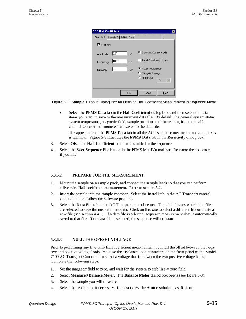
Chapter 5 Section 5.3 Measurements ACT Measurements
Quantum Design PPMS AC Transport Option User’s Manual, Rev. D-1 5-15 October 15, 2003
Figure 5-9. Sample 1 Tab in Dialog Box for Defining Hall Coefficient Measurement in Sequence Mode
• Select the PPMS Data tab in the Hall Coefficient dialog box, and then select the data items you want to save to the measurement data file. By default, the general system status, system temperature, magnetic field, sample position, and the reading from mappable channel 23 (user thermometer) are saved to the data file. The appearance of the PPMS Data tab in all the ACT sequence measurement dialog boxes is identical. Figure 5-8 illustrates the PPMS Data tab in the Resistivity dialog box.
3. Select OK. The Hall Coefficient command is added to the sequence. 4. Select the Save Sequence File button in the PPMS MultiVu tool bar. Re-name the sequence,
if you like.
5.3.6.2 PREPARE FOR THE MEASUREMENT
1. Mount the sample on a sample puck, and connect the sample leads so that you can perform a five-wire Hall coefficient measurement. Refer to section 5.2.
2. Insert the sample into the sample chamber. Select the Install tab in the AC Transport control center, and then follow the software prompts.
3. Select the Data File tab in the AC Transport control center. The tab indicates which data files are selected to save the measurement data. Click on Browse to select a different file or create a new file (see section 4.4.1). If a data file is selected, sequence measurement data is automatically saved to that file. If no data file is selected, the sequence will not start.
5.3.6.3 NULL THE OFFSET VOLTAGE
Prior to performing any five-wire Hall coefficient measurement, you null the offset between the nega-tive and positive voltage leads. You use the “Balance” potentiometers on the front panel of the Model 7100 AC Transport Controller to select a voltage that is between the two positive voltage leads. Complete the following steps:
1. Set the magnetic field to zero, and wait for the system to stabilize at zero field. 2. Select Measure Balance Meter. The Balance Meter dialog box opens (see figure 5-3). 3. Select the sample you will measure. 4. Select the resolution, if necessary. In most cases, the Auto resolution is sufficient.
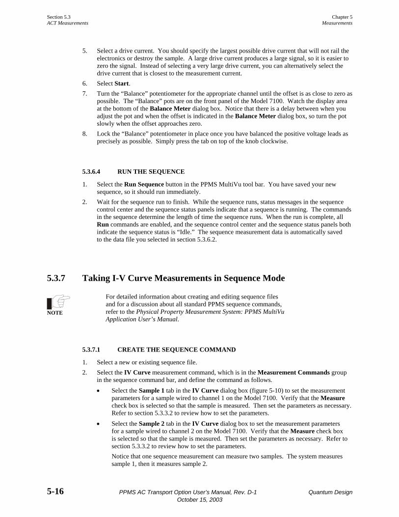
Section 5.3 Chapter 5 ACT Measurements Measurements
5-16 PPMS AC Transport Option User’s Manual, Rev. D-1 Quantum Design October 15, 2003
5. Select a drive current. You should specify the largest possible drive current that will not rail the electronics or destroy the sample. A large drive current produces a large signal, so it is easier to zero the signal. Instead of selecting a very large drive current, you can alternatively select the drive current that is closest to the measurement current.
6. Select Start. 7. Turn the “Balance” potentiometer for the appropriate channel until the offset is as close to zero as
possible. The “Balance” pots are on the front panel of the Model 7100. Watch the display area at the bottom of the Balance Meter dialog box. Notice that there is a delay between when you adjust the pot and when the offset is indicated in the Balance Meter dialog box, so turn the pot slowly when the offset approaches zero.
8. Lock the “Balance” potentiometer in place once you have balanced the positive voltage leads as precisely as possible. Simply press the tab on top of the knob clockwise.
5.3.6.4 RUN THE SEQUENCE
1. Select the Run Sequence button in the PPMS MultiVu tool bar. You have saved your new sequence, so it should run immediately.
2. Wait for the sequence run to finish. While the sequence runs, status messages in the sequence control center and the sequence status panels indicate that a sequence is running. The commands in the sequence determine the length of time the sequence runs. When the run is complete, all Run commands are enabled, and the sequence control center and the sequence status panels both indicate the sequence status is “Idle.” The sequence measurement data is automatically saved to the data file you selected in section 5.3.6.2.
5.3.7 Taking I-V Curve Measurements in Sequence Mode
NOTE
For detailed information about creating and editing sequence files and for a discussion about all standard PPMS sequence commands, refer to the Physical Property Measurement System: PPMS MultiVu Application User’s Manual.
5.3.7.1 CREATE THE SEQUENCE COMMAND
1. Select a new or existing sequence file. 2. Select the IV Curve measurement command, which is in the Measurement Commands group
in the sequence command bar, and define the command as follows. • Select the Sample 1 tab in the IV Curve dialog box (figure 5-10) to set the measurement
parameters for a sample wired to channel 1 on the Model 7100. Verify that the Measure check box is selected so that the sample is measured. Then set the parameters as necessary. Refer to section 5.3.3.2 to review how to set the parameters.
• Select the Sample 2 tab in the IV Curve dialog box to set the measurement parameters for a sample wired to channel 2 on the Model 7100. Verify that the Measure check box is selected so that the sample is measured. Then set the parameters as necessary. Refer to section 5.3.3.2 to review how to set the parameters. Notice that one sequence measurement can measure two samples. The system measures sample 1, then it measures sample 2.

Chapter 5 Section 5.3 Measurements ACT Measurements
Quantum Design PPMS AC Transport Option User’s Manual, Rev. D-1 5-17 October 15, 2003
Figure 5-10. Sample 1 Tab in Dialog Box for Defining I-V Curve Measurement in Sequence Mode
• Select the PPMS Data tab in the IV Curve dialog box, and then select the data items you want to save to the measurement data file. By default, the general system status, system temperature, magnetic field, sample position, and the reading from mappable channel 23 (user thermometer) are saved to the data file. The appearance of the PPMS Data tab in all the ACT sequence measurement dialog boxes is identical. Figure 5-8 illustrates the PPMS Data tab in the Resistivity dialog box.
3. Select OK. The IV Curve command is added to the sequence. 4. Select the Save Sequence File button in the PPMS MultiVu tool bar. Re-name the sequence,
if you like.
5.3.7.2 PREPARE FOR THE MEASUREMENT
1. Mount the sample on a sample puck, and connect the sample leads so that you can perform a four-wire resistivity measurement. Refer to section 5.2.
2. Insert the sample into the sample chamber. Select the Install tab in the AC Transport control center, and then follow the software prompts.
3. Select the Data File tab in the AC Transport control center. The tab indicates which data files are selected to save the measurement data. Click on Browse to select a different file or create a new file (see section 4.4.1). If a data file is selected, sequence measurement data is automatically saved to that file. If no data file is selected, the sequence will not start.
5.3.7.3 RUN THE SEQUENCE
1. Select the Run Sequence button in the PPMS MultiVu tool bar. You have saved your new sequence, so it should run immediately.
2. Wait for the sequence run to finish. While the sequence runs, status messages in the sequence control center and the sequence status panels indicate that a sequence is running. The commands in the sequence determine the length of time the sequence runs. When the run is complete, all Run commands are enabled, and the sequence control center and the sequence status panels both indicate the sequence status is “Idle.” The sequence measurement data is automatically saved to the data file you selected in section 5.3.7.2.
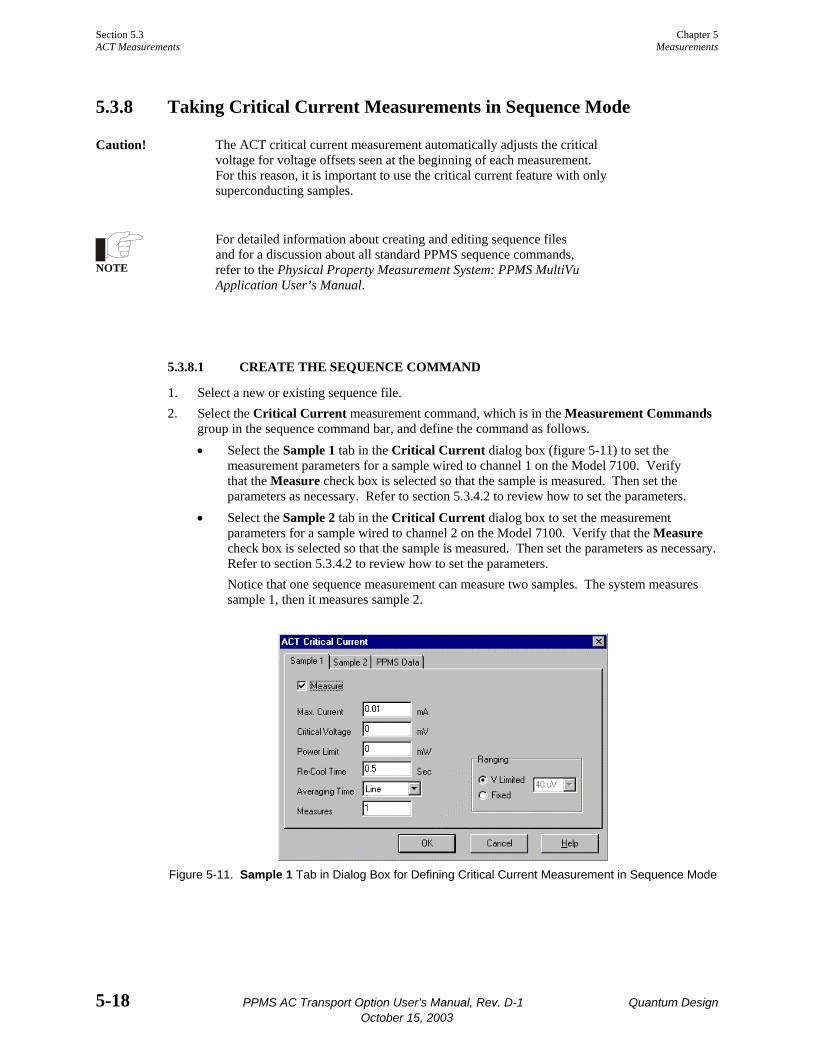
Section 5.3 Chapter 5 ACT Measurements Measurements
5-18 PPMS AC Transport Option User’s Manual, Rev. D-1 Quantum Design October 15, 2003
5.3.8 Taking Critical Current Measurements in Sequence Mode
Caution! The ACT critical current measurement automatically adjusts the critical voltage for voltage offsets seen at the beginning of each measurement. For this reason, it is important to use the critical current feature with only superconducting samples.
NOTE
For detailed information about creating and editing sequence files and for a discussion about all standard PPMS sequence commands, refer to the Physical Property Measurement System: PPMS MultiVu Application User’s Manual.
5.3.8.1 CREATE THE SEQUENCE COMMAND
1. Select a new or existing sequence file. 2. Select the Critical Current measurement command, which is in the Measurement Commands
group in the sequence command bar, and define the command as follows. • Select the Sample 1 tab in the Critical Current dialog box (figure 5-11) to set the
measurement parameters for a sample wired to channel 1 on the Model 7100. Verify that the Measure check box is selected so that the sample is measured. Then set the parameters as necessary. Refer to section 5.3.4.2 to review how to set the parameters.
• Select the Sample 2 tab in the Critical Current dialog box to set the measurement parameters for a sample wired to channel 2 on the Model 7100. Verify that the Measure check box is selected so that the sample is measured. Then set the parameters as necessary. Refer to section 5.3.4.2 to review how to set the parameters. Notice that one sequence measurement can measure two samples. The system measures sample 1, then it measures sample 2.
Figure 5-11. Sample 1 Tab in Dialog Box for Defining Critical Current Measurement in Sequence Mode

Chapter 5 Section 5.3 Measurements ACT Measurements
Quantum Design PPMS AC Transport Option User’s Manual, Rev. D-1 5-19 October 15, 2003
• Select the PPMS Data tab in the Critical Current dialog box, and then select the data items you want to save to the measurement data file. By default, the general system status, system temperature, magnetic field, sample position, and the reading from mappable channel 23 (user thermometer) are saved to the data file. The appearance of the PPMS Data tab in all the ACT sequence measurement dialog boxes is identical. Figure 5-8 illustrates the PPMS Data tab in the Resistivity dialog box.
3. Select OK. The Critical Current command is added to the sequence. 4. Select the Save Sequence File button in the PPMS MultiVu tool bar. Re-name the sequence,
if you like.
5.3.8.2 PREPARE FOR THE MEASUREMENT
1. Mount the sample on a sample puck, and connect the sample leads so that you can perform a four-wire resistivity measurement. Refer to section 5.2.
2. Insert the sample into the sample chamber. Select the Install tab in the AC Transport control center, and then follow the software prompts.
3. Select the Data File tab in the AC Transport control center. The tab indicates which data files are selected to save the measurement data. Click on Browse to select a different file or create a new file (see section 4.4.1). If a data file is selected, sequence measurement data is automatically saved to that file. If no data file is selected, the sequence will not start.
5.3.8.3 RUN THE SEQUENCE
1. Select the Run Sequence button in the PPMS MultiVu tool bar. You have saved your new sequence, so it should run immediately.
2. Wait for the sequence run to finish. While the sequence runs, status messages in the sequence control center and the sequence status panels indicate that a sequence is running. The commands in the sequence determine the length of time the sequence runs. When the run is complete, all Run commands are enabled, and the sequence control center and the sequence status panels both indicate the sequence status is “Idle.” The sequence measurement data is automatically saved to the data file you selected in section 5.3.8.2.

Quantum Design PPMS AC Transport Option User’s Manual, Rev. D-1 6-1 October 15, 2003
C H A P T E R 6
Operation with the Helium-3 System
6.1 Introduction This chapter contains the following information:
• Section 6.2 presents an overview of ACT operation with the Helium-3 system.
• Section 6.4 contains interconnection tables for the ACT/Helium-3 probe cable.
• Section 6.3 describes how to take ACT measurements when using the Helium-3 system.
6.2 Overview of ACT Operation with the Helium-3 System The ACT option may be used with the PPMS Helium-3 Refrigerator System insert (Model P825). Use of the Helium-3 insert allows ACT measurements to be performed to below 0.4 K. The Helium-3 system is designed to be as transparent as possible so that ACT operations are performed normally when the Helium-3 insert is in use.
The internal wiring in the Helium-3 insert cannot handle sample currents larger than approximately 20 mA. Consequently, under normal operating conditions, the ACT software automatically detects the presence of the Helium-3 insert and limits measurements to 20 mA. Nonetheless, you should never purposely set a current larger than 20 mA in the event that the software does not properly detect the insert.
When the ACT system uses the Helium-3 insert, four of the sample chamber wires must be dedicated to the Helium-3 system platform thermometer. Only eight wires⎯rather than the normal twelve⎯ are available for ACT measurements, so only one sample can be measured at a time. A special probe cable (see figure 6-1) splits off the four thermometer wires that go to the user bridge board from the dedicated ACT wiring that goes to the Model 7100 AC Transport Controller.
Section 6.3 Chapter 6 ACT Measurements with the Helium-3 System Operation with the Helium-3 System
6-2 PPMS AC Transport Option User’s Manual, Rev. D-1 Quantum Design October 15, 2003
6.3 ACT Measurements with the Helium-3 System Please refer to the Physical Property Measurement System: Helium-3 Refrigerator System User’s Manual for complete instructions on handling and operating the PPMS Helium-3 system.
6.3.1 Measurement Setup
6.3.1.1 PREPARE FOR THE MEASUREMENT
Caution! Avoid stressing the shaft of the Helium-3 refrigerator probe in any way while you are inserting the refrigerator probe into or removing it from the PPMS sample chamber. The material out of which the probe shaft is constructed is thin and fragile and can easily bend or dent.
1. Remove the Helium-3 refrigerator probe from the sample chamber. Refer to the Physical Property Measurement System: Helium-3 Refrigerator System User’s Manual for detailed instructions.
2. Quit the Helium-3 software application if the application is running. 3. Install the ACT/Helium-3 probe cable (part number 3084-518) by plugging the connectors on
the cable into the ports indicated by the cable labels. • Plug the 14-pin gray Lemo connector into the gray, color-coded port on the probe head. • Plug the connector on the cable labeled “P1 Sample Current Out” into the “P1−Sample
Current Out” port on the rear of the Model 7100. • Plug the connector on the cable labeled “P5 Sample Voltage In” into the “P5−Sample
Voltage In” port on the rear of the Model 7100. • Plug the 4-pin Lemo connector on the cable labeled “P1 User Bridge” into the “P1−User
Bridge” port on the rear of the Model 6000.
Figure 6-1. ACT/Helium-3 Probe Cable

Chapter 6 Section 6.3 Operation with the Helium-3 System ACT Measurements with the Helium-3 System
Quantum Design PPMS AC Transport Option User’s Manual, Rev. D-1 6-3 October 15, 2003
6.3.1.2 INSTALL THE SAMPLE
1. Mount the sample on a Helium-3 sample mount (part number 4092-610). Note that at temperatures below 1 K, intimate thermal contact between the sample and the copper holder is very important to reduce temperature errors. A thin film of Apiezon N Grease works well to aid thermal contact. Apiezon N Grease is supplied with the Model P825 Helium-3 insert.
2. Refer to figure 6-2 below to wire the sample to the stage. The plug-in sample mount is labeled for use with the user bridge board, but by following the wiring schematics in figure 6-2, you can use it with the ACT option. The labels on the sample mount are not correct when you use the ACT/Helium-3 probe cable shown in figure 6-1.
Figure 6-2. Sample-Wiring Diagrams for the Helium-3 Option
3. Attach the plug-in sample stage to the Helium-3 refrigerator probe. Refer to the Physical Property Measurement System: Helium-3 Refrigerator System User’s Manual for detailed instructions.
4. Insert the Helium-3 refrigerator probe into the sample chamber. Refer to the Physical Property Measurement System: Helium-3 Refrigerator System User’s Manual for detailed instructions.
6.3.1.3 START UP THE SOFTWARE
1. Start up PPMS MultiVu if the application is not running. 2. Activate the Helium-3 option in PPMS MultiVu. Do the following: (a) select Utilities
Activate Option, (b) click on Helium3 under the Available Options heading, and then (c) select the Activate button.
Section 6.3 Chapter 6 ACT Measurements with the Helium-3 System Operation with the Helium-3 System
6-4 PPMS AC Transport Option User’s Manual, Rev. D-1 Quantum Design October 15, 2003
3. Activate the ACT option in PPMS MultiVu. Do the following: (a) select Utilities Activate Option, (b) click on AC Transport under the Available Options heading, and then (c) select the Activate button. Both the Helium-3 software and ACT software must be running before you can initiate a measurement.
4. Initiate a Helium-3 system test by using PPMS MultiVu or the Model 6000 front panel to set an initial temperature (for example, 300 K). The Helium-3 temperature control is activated on the first Temperature Set command. The software checks out the Helium-3 system, downloads any necessary configuration data to the Model 6000 console, and begins controlling temperature.
6.3.2 Performing Measurements Once the Helium-3 refrigerator probe is inserted in the sample chamber and the Helium-3 and ACT software applications are running, you may take ACT measurements at temperatures as low as 0.4 K. You take ACT measurements and write sequences according to the usual procedures described in section 5.3. Note, however, that when the refrigerator probe is installed, the ACT current output is limited to 20 mA or less.
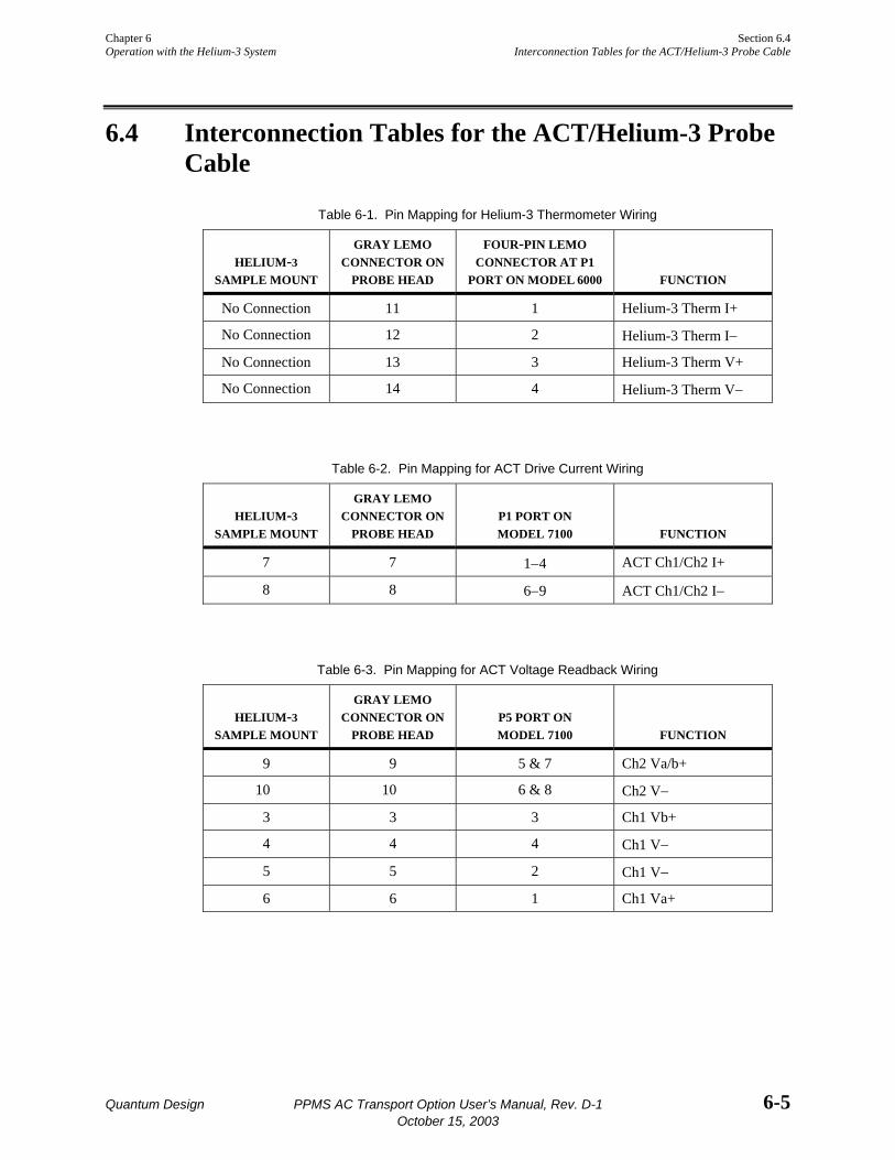
Chapter 6 Section 6.4 Operation with the Helium-3 System Interconnection Tables for the ACT/Helium-3 Probe Cable
Quantum Design PPMS AC Transport Option User’s Manual, Rev. D-1 6-5 October 15, 2003
6.4 Interconnection Tables for the ACT/Helium-3 Probe Cable
Table 6-1. Pin Mapping for Helium-3 Thermometer Wiring
HELIUM-3
SAMPLE MOUNT
GRAY LEMO CONNECTOR ON
PROBE HEAD
FOUR-PIN LEMO CONNECTOR AT P1
PORT ON MODEL 6000
FUNCTION
No Connection 11 1 Helium-3 Therm I+
No Connection 12 2 Helium-3 Therm I−
No Connection 13 3 Helium-3 Therm V+
No Connection 14 4 Helium-3 Therm V−
Table 6-2. Pin Mapping for ACT Drive Current Wiring
HELIUM-3
SAMPLE MOUNT
GRAY LEMO CONNECTOR ON
PROBE HEAD
P1 PORT ON MODEL 7100
FUNCTION
7 7 1−4 ACT Ch1/Ch2 I+
8 8 6−9 ACT Ch1/Ch2 I−
Table 6-3. Pin Mapping for ACT Voltage Readback Wiring
HELIUM-3
SAMPLE MOUNT
GRAY LEMO CONNECTOR ON
PROBE HEAD
P5 PORT ON MODEL 7100
FUNCTION
9 9 5 & 7 Ch2 Va/b+
10 10 6 & 8 Ch2 V−
3 3 3 Ch1 Vb+
4 4 4 Ch1 V−
5 5 2 Ch1 V−
6 6 1 Ch1 Va+
Quantum Design PPMS AC Transport Option User’s Manual, Rev. D-1 7-1 October 15, 2003
C H A P T E R 7
Operation with the Horizontal Rotator
7.1 Introduction This chapter contains the following information:
• Section 7.2 presents an overview of ACT operation with the Horizontal Rotator.
• Section 7.4 describes how to take ACT measurements when using the Horizontal Rotator.
• Section 7.3 explains how to configure the rotator thermometer.
• Section 7.5 contains interconnection tables for the ACT/Horizontal Rotator probe cable.
7.2 Overview of ACT Operation with the Horizontal Rotator Many researchers find it useful to be able to rotate samples in the magnetic field of the PPMS sample chamber while measuring with the ACT system. This can be accomplished by using the PPMS Horizontal Rotator option in conjunction with the ACT option. However, you must keep in mind some important considerations when you use the two options together to take measurements. This chapter details those important considerations. Using the ACT system with the Horizontal Rotator also requires the hardware supplied in the Horizontal Rotator kit for the ACT option (part number 4084-308). The kit includes a special cable and special sample holder boards.
When the ACT system uses the Horizontal Rotator probe, four of the sample chamber wires must be connected directly to the rotator thermometer. Only eight wires⎯rather than the normal twelve⎯are available for ACT measurements. A special four-way probe cable (see figure 7-1) splits off the four thermometer wires that go to the system bridge board from the dedicated ACT wiring that goes to the Model 7100 AC Transport Controller.
Refer to the Physical Property Measurement System: Horizontal Rotator Option User’s Manual for more information about using the Horizontal Rotator.
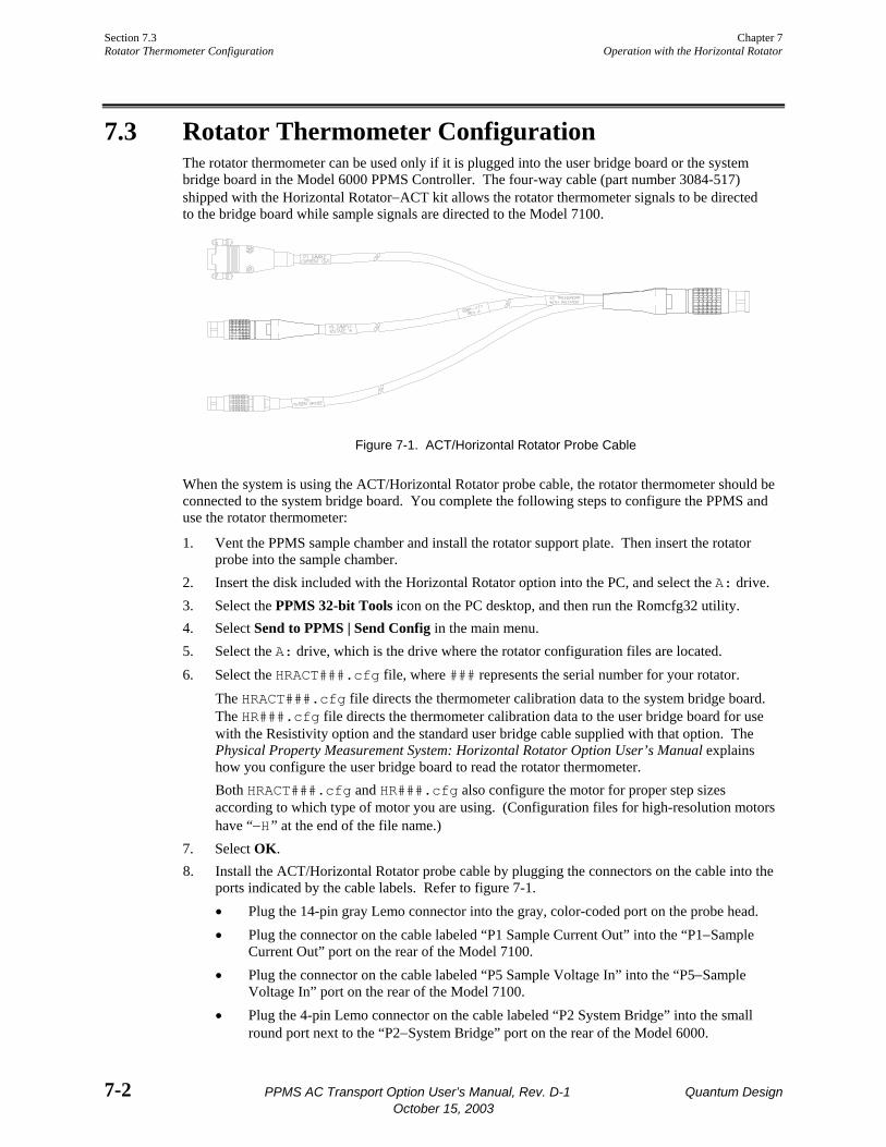
Section 7.3 Chapter 7 Rotator Thermometer Configuration Operation with the Horizontal Rotator
7-2 PPMS AC Transport Option User’s Manual, Rev. D-1 Quantum Design October 15, 2003
7.3 Rotator Thermometer Configuration The rotator thermometer can be used only if it is plugged into the user bridge board or the system bridge board in the Model 6000 PPMS Controller. The four-way cable (part number 3084-517) shipped with the Horizontal Rotator−ACT kit allows the rotator thermometer signals to be directed to the bridge board while sample signals are directed to the Model 7100.
Figure 7-1. ACT/Horizontal Rotator Probe Cable
When the system is using the ACT/Horizontal Rotator probe cable, the rotator thermometer should be connected to the system bridge board. You complete the following steps to configure the PPMS and use the rotator thermometer:
1. Vent the PPMS sample chamber and install the rotator support plate. Then insert the rotator probe into the sample chamber.
2. Insert the disk included with the Horizontal Rotator option into the PC, and select the A: drive. 3. Select the PPMS 32-bit Tools icon on the PC desktop, and then run the Romcfg32 utility. 4. Select Send to PPMS | Send Config in the main menu. 5. Select the A: drive, which is the drive where the rotator configuration files are located. 6. Select the HRACT###.cfg file, where ### represents the serial number for your rotator.
The HRACT###.cfg file directs the thermometer calibration data to the system bridge board. The HR###.cfg file directs the thermometer calibration data to the user bridge board for use with the Resistivity option and the standard user bridge cable supplied with that option. The Physical Property Measurement System: Horizontal Rotator Option User’s Manual explains how you configure the user bridge board to read the rotator thermometer. Both HRACT###.cfg and HR###.cfg also configure the motor for proper step sizes according to which type of motor you are using. (Configuration files for high-resolution motors have “−H” at the end of the file name.)
7. Select OK. 8. Install the ACT/Horizontal Rotator probe cable by plugging the connectors on the cable into the
ports indicated by the cable labels. Refer to figure 7-1. • Plug the 14-pin gray Lemo connector into the gray, color-coded port on the probe head. • Plug the connector on the cable labeled “P1 Sample Current Out” into the “P1−Sample
Current Out” port on the rear of the Model 7100. • Plug the connector on the cable labeled “P5 Sample Voltage In” into the “P5−Sample
Voltage In” port on the rear of the Model 7100. • Plug the 4-pin Lemo connector on the cable labeled “P2 System Bridge” into the small
round port next to the “P2−System Bridge” port on the rear of the Model 6000.
Chapter 7 Section 7.3 Operation with the Horizontal Rotator Rotator Thermometer Configuration
Quantum Design PPMS AC Transport Option User’s Manual, Rev. D-1 7-3 October 15, 2003
he PPMS now uses the rotator thermometer to control the temperature and the rotator motor is configured properly. Data files written by the ACT software now report the rotator thermometer reading, in K, under the item labeled “PPMS Map 20.” For ACT options shipped prior to March 1997, a simple modification to the HRACT###.cfg file is required to allow the ACT software to report the rotator temperature. Quantum Design Customer Service can help you with this file modification.
If you connect the standard ACT “Y” connection cable to the probe head while the Horizontal Rotator probe is installed, you are essentially connecting a high-power current source to a calibrated, negative-temperature-coefficient, resistive thermometer with resistance between 20−10,000 Ω. Depending on its temperature, this thermometer can be damaged by as little as 10 µA to 10 mA, so you should not use the standard cable when the Horizontal Rotator probe is installed in the sample chamber.
Caution! To avoid damaging the rotator thermometer when the Horizontal Rotator probe is installed in the sample chamber, use only the ACT/Horizontal Rotator probe cable, and never use the standard ACT “Y” connection cable.
7.3.1 Turning Off UserTemp Configuring the Horizontal Rotator by transmitting the configuration files to the Model 6000 ROM also turns on UserTemp so that the rotator thermometer is used for temperature control. When you complete your experiments with the Horizontal Rotator and remove the Horizontal Rotator probe from the sample chamber, you should turn off this thermometer. Complete the following steps:
1. Open Monitor QD-6000 in the PPMS 32-bit Tools folder, or select Utilities Send GPIB Commands in the PPMS MultiVu interface.
2. Type USERTEMP 0. 3. Press <Enter> to execute this command.
If you do not turn off UserTemp, the resistance read off system bridge channel 4 is used to control the temperature in the sample chamber. If UserTemp remains on, but no user thermometer is installed⎯ that is, the Horizontal Rotator probe is removed from the PPMS⎯the temperature control defaults back to the system thermometers, but returns to system bridge channel 4 whenever a resistance is perceived there. If the resistance is not that of the calibrated rotator thermometer, the temperature controller appears broken, so be sure to turn off UserTemp when you are not using the Horizontal Rotator or another customized calibrated thermometer.
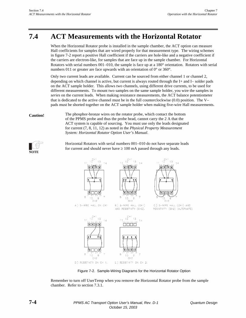
Section 7.4 Chapter 7 ACT Measurements with the Horizontal Rotator Operation with the Horizontal Rotator
7-4 PPMS AC Transport Option User’s Manual, Rev. D-1 Quantum Design October 15, 2003
7.4 ACT Measurements with the Horizontal Rotator When the Horizontal Rotator probe is installed in the sample chamber, the ACT option can measure Hall coefficients for samples that are wired properly for that measurement type. The wiring schemes in figure 7-2 report a positive Hall coefficient if the carriers are hole-like and a negative coefficient if the carriers are electron-like, for samples that are face up in the sample chamber. For Horizontal Rotators with serial numbers 001−010, the sample is face up at a 180° orientation. Rotators with serial numbers 011 or greater are face upwards with an orientation of 0° or 360°.
Only two current leads are available. Current can be sourced from either channel 1 or channel 2, depending on which channel is active, but current is always routed through the I+ and I− solder pads on the ACT sample holder. This allows two channels, using different drive currents, to be used for different measurements. To mount two samples on the same sample holder, you wire the samples in series on the current leads. When making resistance measurements, the ACT balance potentiometer that is dedicated to the active channel must be in the full counterclockwise (0.0) position. The V− pads must be shorted together on the ACT sample holder when making five-wire Hall measurements.
Caution! The phosphor-bronze wires on the rotator probe, which contact the bottom of the PPMS probe and thus the probe head, cannot carry the 2 A that the ACT system is capable of sourcing. You must use only the leads designated for current (7, 8, 11, 12) as noted in the Physical Property Measurement System: Horizontal Rotator Option User’s Manual.
NOTE
Horizontal Rotators with serial numbers 001−010 do not have separate leads for current and should never have ≥ 100 mA passed through any leads.
Figure 7-2. Sample-Wiring Diagrams for the Horizontal Rotator Option
Remember to turn off UserTemp when you remove the Horizontal Rotator probe from the sample chamber. Refer to section 7.3.1.
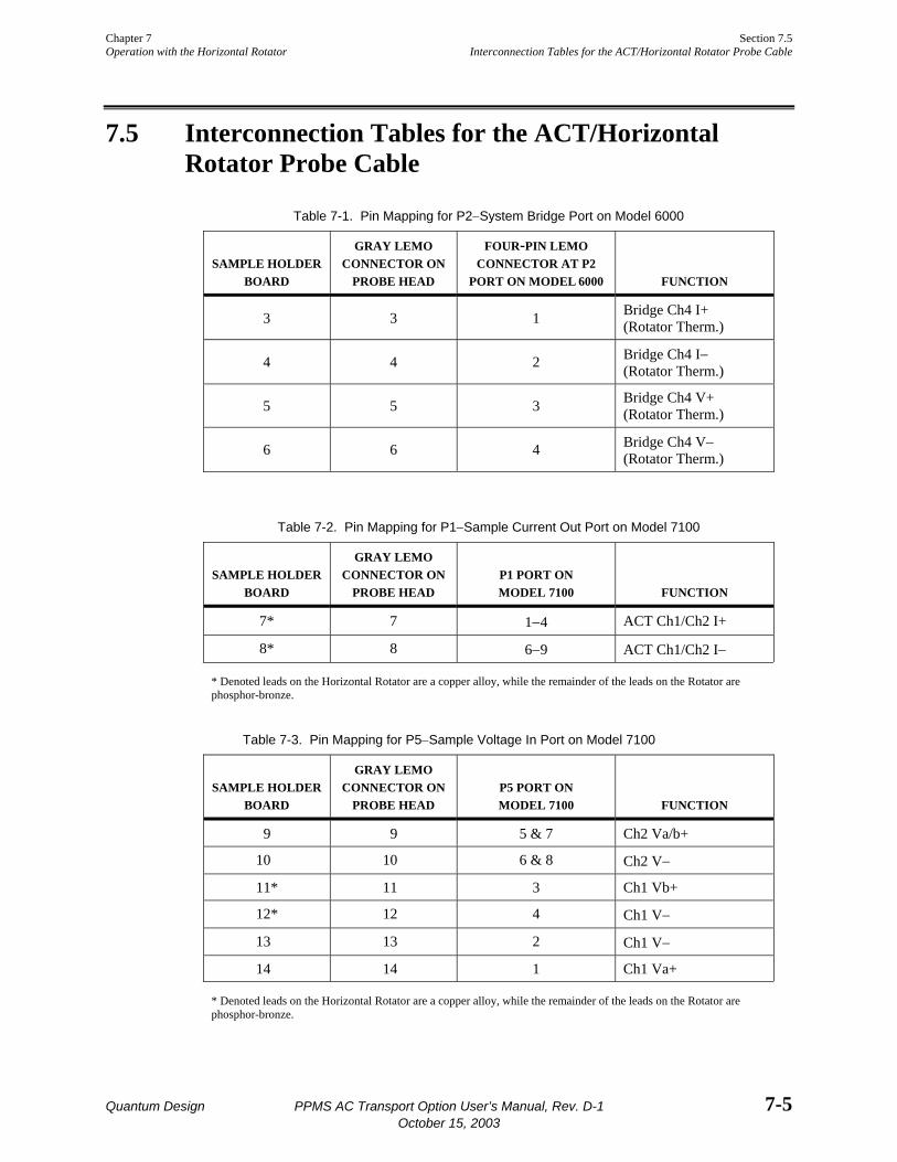
Chapter 7 Section 7.5 Operation with the Horizontal Rotator Interconnection Tables for the ACT/Horizontal Rotator Probe Cable
Quantum Design PPMS AC Transport Option User’s Manual, Rev. D-1 7-5 October 15, 2003
7.5 Interconnection Tables for the ACT/Horizontal Rotator Probe Cable
Table 7-1. Pin Mapping for P2−System Bridge Port on Model 6000
SAMPLE HOLDER
BOARD
GRAY LEMO CONNECTOR ON
PROBE HEAD
FOUR-PIN LEMO CONNECTOR AT P2
PORT ON MODEL 6000
FUNCTION
3 3 1 Bridge Ch4 I+ (Rotator Therm.)
4 4 2 Bridge Ch4 I− (Rotator Therm.)
5 5 3 Bridge Ch4 V+ (Rotator Therm.)
6 6 4 Bridge Ch4 V− (Rotator Therm.)
Table 7-2. Pin Mapping for P1−Sample Current Out Port on Model 7100
SAMPLE HOLDER
BOARD
GRAY LEMO CONNECTOR ON
PROBE HEAD
P1 PORT ON MODEL 7100
FUNCTION
7* 7 1−4 ACT Ch1/Ch2 I+
8* 8 6−9 ACT Ch1/Ch2 I−
* Denoted leads on the Horizontal Rotator are a copper alloy, while the remainder of the leads on the Rotator are phosphor-bronze.
Table 7-3. Pin Mapping for P5−Sample Voltage In Port on Model 7100
SAMPLE HOLDER
BOARD
GRAY LEMO CONNECTOR ON
PROBE HEAD
P5 PORT ON MODEL 7100
FUNCTION
9 9 5 & 7 Ch2 Va/b+
10 10 6 & 8 Ch2 V−
11* 11 3 Ch1 Vb+
12* 12 4 Ch1 V−
13 13 2 Ch1 V−
14 14 1 Ch1 Va+
* Denoted leads on the Horizontal Rotator are a copper alloy, while the remainder of the leads on the Rotator are phosphor-bronze.
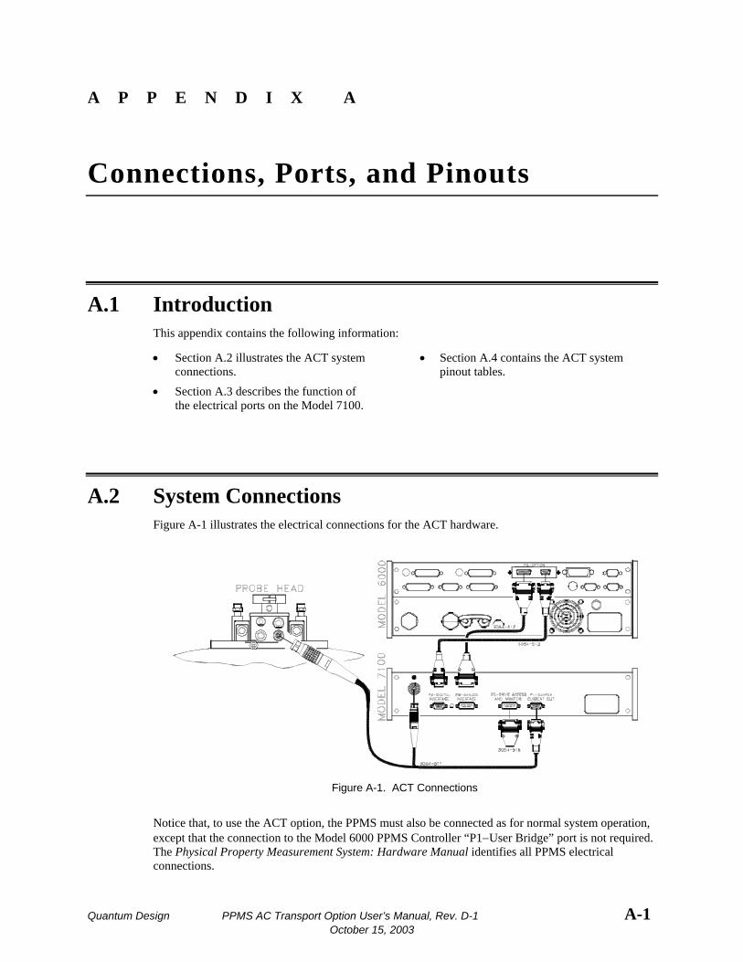
Quantum Design PPMS AC Transport Option User’s Manual, Rev. D-1 A-1 October 15, 2003
A P P E N D I X A
Connections, Ports, and Pinouts
A.1 Introduction This appendix contains the following information:
• Section A.2 illustrates the ACT system connections.
• Section A.4 contains the ACT system pinout tables.
• Section A.3 describes the function of the electrical ports on the Model 7100.
A.2 System Connections Figure A-1 illustrates the electrical connections for the ACT hardware.
Figure A-1. ACT Connections
Notice that, to use the ACT option, the PPMS must also be connected as for normal system operation, except that the connection to the Model 6000 PPMS Controller “P1−User Bridge” port is not required. The Physical Property Measurement System: Hardware Manual identifies all PPMS electrical connections.

Section A.3 Appendix A Model 7100 Rear Panel Ports Connections, Ports, and Pinouts
A-2 PPMS AC Transport Option User’s Manual, Rev. D-1 Quantum Design October 15, 2003
A.3 Model 7100 Rear Panel Ports Table A-1 describes the function of each electrical port on the rear panel of the Model 7100 AC Transport Controller. Chapter 3 discusses the monitor outputs on the front panel of the Model 7100.
Figure A-2. Rear Panel on Model 7100 AC Transport Controller
Table A-1. Electrical Ports on Model 7100 Rear Panel
PORT FUNCTION
P1−Sample Current Out Provides current excitation for sample. “Y” cable is used to connect port to gray Lemo connector on probe head. Opposite end of “Y” cable connects to P5 port on Model 7100.
P2−Drive Access and Monitor For monitoring current through sample and normally contains set of jumpers. Removing jumpers allows ammeters to be inserted into circuit but breaks drive circuit open, essentially disabling system completely, if circuit is not completed in some other manner. One pin on P2 port is reserved to allow synchronization of other instruments with the excitation signal. This capability is for future development.
P3−Analog Interface 15-pin “D” connector that sends detected sample signal to AC board in Model 6000, so signal can be digitized and recorded. P3 port is connected to P3 port on Model 6000.
P4−Digital Interface 9-pin “D” connector that is input for digital signals from AC board in Model 6000. These signals are amplified to provide excitation signal for sample. P4 port is connected to P3 port on Model 6000.
P5−Sample Signal In 8-pin Lemo connector marks location where voltage signal from sample is directed into Model 7100. Opposite ends of “Y” cable making this connection attach to P1 port on Model 7100 and to gray Lemo connector on probe head.
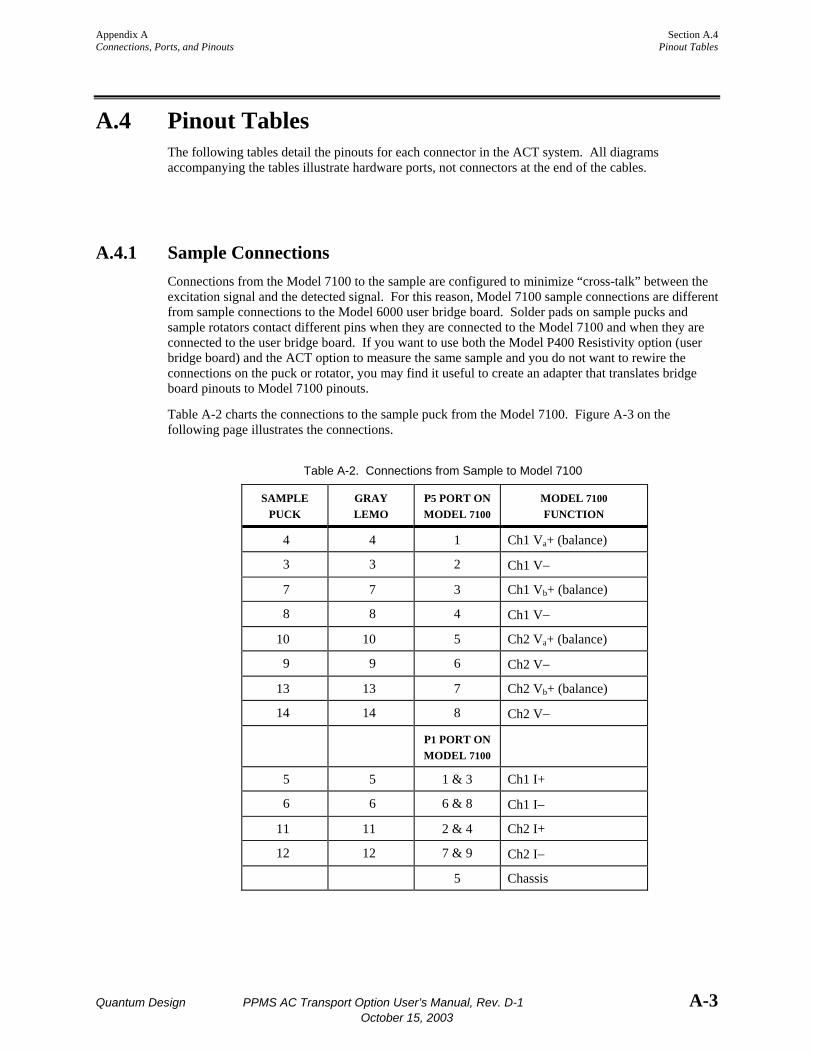
Appendix A Section A.4 Connections, Ports, and Pinouts Pinout Tables
Quantum Design PPMS AC Transport Option User’s Manual, Rev. D-1 A-3 October 15, 2003
A.4 Pinout Tables The following tables detail the pinouts for each connector in the ACT system. All diagrams accompanying the tables illustrate hardware ports, not connectors at the end of the cables.
A.4.1 Sample Connections Connections from the Model 7100 to the sample are configured to minimize “cross-talk” between the excitation signal and the detected signal. For this reason, Model 7100 sample connections are different from sample connections to the Model 6000 user bridge board. Solder pads on sample pucks and sample rotators contact different pins when they are connected to the Model 7100 and when they are connected to the user bridge board. If you want to use both the Model P400 Resistivity option (user bridge board) and the ACT option to measure the same sample and you do not want to rewire the connections on the puck or rotator, you may find it useful to create an adapter that translates bridge board pinouts to Model 7100 pinouts.
Table A-2 charts the connections to the sample puck from the Model 7100. Figure A-3 on the following page illustrates the connections.
Table A-2. Connections from Sample to Model 7100
SAMPLE PUCK
GRAY LEMO
P5 PORT ON MODEL 7100
MODEL 7100 FUNCTION
4 4 1 Ch1 Va+ (balance)
3 3 2 Ch1 V−
7 7 3 Ch1 Vb+ (balance)
8 8 4 Ch1 V−
10 10 5 Ch2 Va+ (balance)
9 9 6 Ch2 V−
13 13 7 Ch2 Vb+ (balance)
14 14 8 Ch2 V−
P1 PORT ON MODEL 7100
5 5 1 & 3 Ch1 I+
6 6 6 & 8 Ch1 I−
11 11 2 & 4 Ch2 I+
12 12 7 & 9 Ch2 I−
5 Chassis
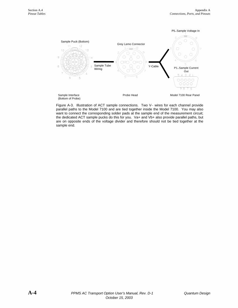
Section A.4 Appendix A Pinout Tables Connections, Ports, and Pinouts
A-4 PPMS AC Transport Option User’s Manual, Rev. D-1 Quantum Design October 15, 2003
P5−Sample Voltage In
Grey Lemo ConnectorSample Puck (Bottom)
P1−Sample CurrentOut
Sample TubeWiring
Y-Cable
Sample Interface Probe Head Model 7100 Rear Panel (Bottom of Probe)
Figure A-3. Illustration of ACT sample connections. Two V− wires for each channel provide parallel paths to the Model 7100 and are tied together inside the Model 7100. You may also want to connect the corresponding solder pads at the sample end of the measurement circuit; the dedicated ACT sample pucks do this for you. Va+ and Vb+ also provide parallel paths, but are on opposite ends of the voltage divider and therefore should not be tied together at the sample end.
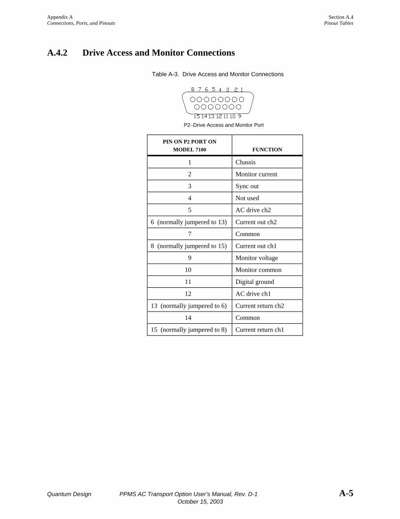
Appendix A Section A.4 Connections, Ports, and Pinouts Pinout Tables
Quantum Design PPMS AC Transport Option User’s Manual, Rev. D-1 A-5 October 15, 2003
A.4.2 Drive Access and Monitor Connections
Table A-3. Drive Access and Monitor Connections
P2−Drive Access and Monitor Port
PIN ON P2 PORT ON MODEL 7100
FUNCTION
1 Chassis
2 Monitor current
3 Sync out
4 Not used
5 AC drive ch2
6 (normally jumpered to 13) Current out ch2
7 Common
8 (normally jumpered to 15) Current out ch1
9 Monitor voltage
10 Monitor common
11 Digital ground
12 AC drive ch1
13 (normally jumpered to 6) Current return ch2
14 Common
15 (normally jumpered to 8) Current return ch1
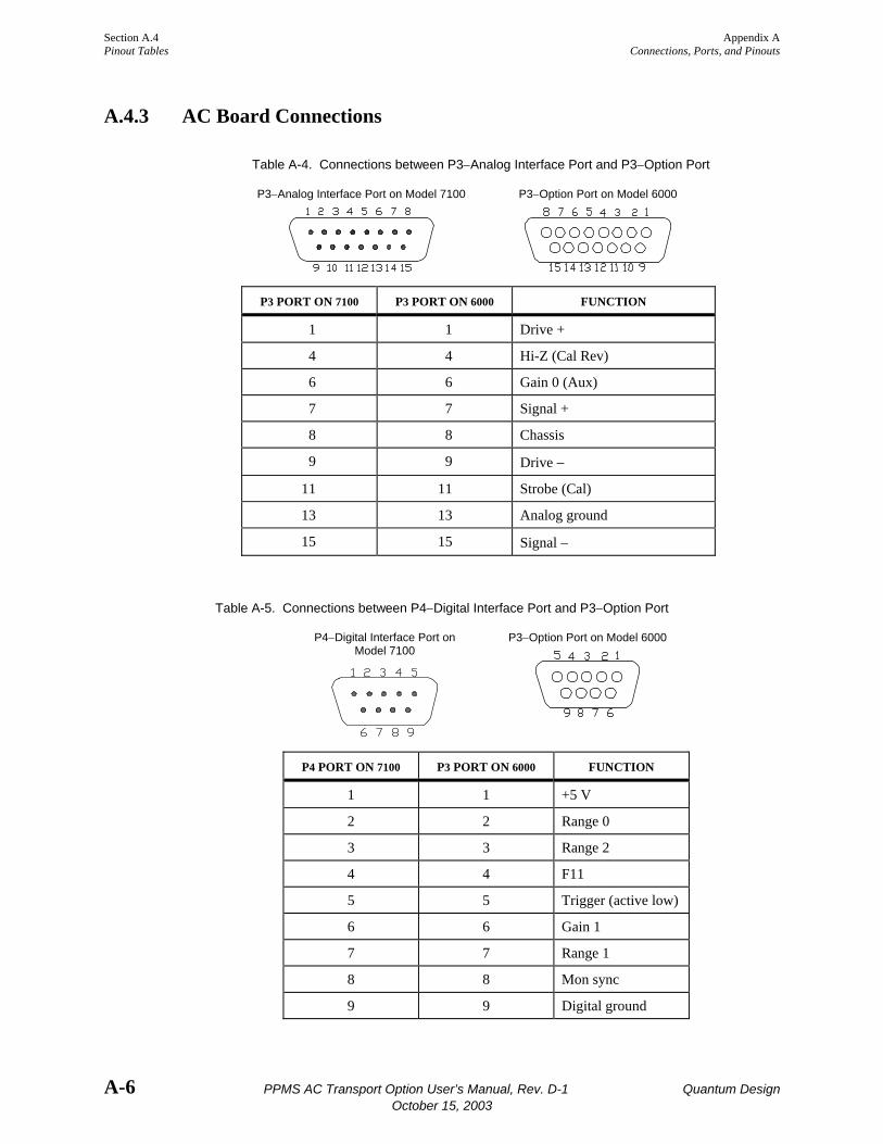
Section A.4 Appendix A Pinout Tables Connections, Ports, and Pinouts
A-6 PPMS AC Transport Option User’s Manual, Rev. D-1 Quantum Design October 15, 2003
A.4.3 AC Board Connections
Table A-4. Connections between P3−Analog Interface Port and P3−Option Port
P3−Analog Interface Port on Model 7100
P3−Option Port on Model 6000
P3 PORT ON 7100 P3 PORT ON 6000 FUNCTION
1 1 Drive +
4 4 Hi-Z (Cal Rev)
6 6 Gain 0 (Aux)
7 7 Signal +
8 8 Chassis
9 9 Drive −
11 11 Strobe (Cal)
13 13 Analog ground
15 15 Signal −
Table A-5. Connections between P4−Digital Interface Port and P3−Option Port
P4−Digital Interface Port on Model 7100
P3−Option Port on Model 6000
P4 PORT ON 7100 P3 PORT ON 6000 FUNCTION
1 1 +5 V
2 2 Range 0
3 3 Range 2
4 4 F11
5 5 Trigger (active low)
6 6 Gain 1
7 7 Range 1
8 8 Mon sync
9 9 Digital ground
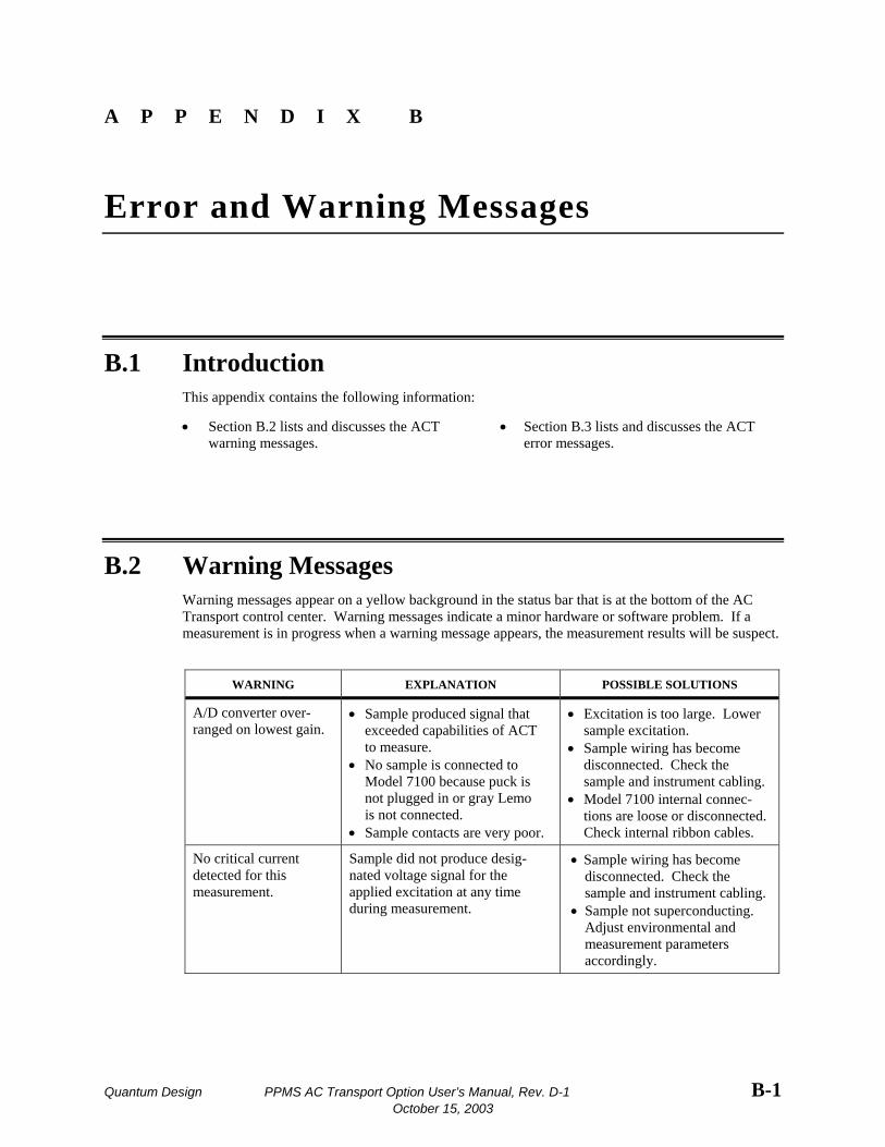
Quantum Design PPMS AC Transport Option User’s Manual, Rev. D-1 B-1 October 15, 2003
A P P E N D I X B
Error and Warning Messages
B.1 Introduction This appendix contains the following information:
• Section B.2 lists and discusses the ACT warning messages.
• Section B.3 lists and discusses the ACT error messages.
B.2 Warning Messages Warning messages appear on a yellow background in the status bar that is at the bottom of the AC Transport control center. Warning messages indicate a minor hardware or software problem. If a measurement is in progress when a warning message appears, the measurement results will be suspect.
WARNING EXPLANATION POSSIBLE SOLUTIONS
A/D converter over-ranged on lowest gain.
• Sample produced signal that exceeded capabilities of ACT to measure.
• No sample is connected to Model 7100 because puck is not plugged in or gray Lemo is not connected.
• Sample contacts are very poor.
• Excitation is too large. Lower sample excitation.
• Sample wiring has become disconnected. Check the sample and instrument cabling.
• Model 7100 internal connec-tions are loose or disconnected. Check internal ribbon cables.
No critical current detected for this measurement.
Sample did not produce desig-nated voltage signal for the applied excitation at any time during measurement.
• Sample wiring has become disconnected. Check the sample and instrument cabling.
• Sample not superconducting. Adjust environmental and measurement parameters accordingly.
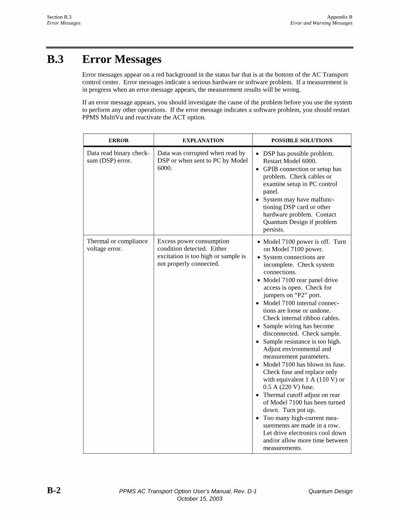
Section B.3 Appendix B Error Messages Error and Warning Messages
B-2 PPMS AC Transport Option User’s Manual, Rev. D-1 Quantum Design October 15, 2003
B.3 Error Messages Error messages appear on a red background in the status bar that is at the bottom of the AC Transport control center. Error messages indicate a serious hardware or software problem. If a measurement is in progress when an error message appears, the measurement results will be wrong.
If an error message appears, you should investigate the cause of the problem before you use the system to perform any other operations. If the error message indicates a software problem, you should restart PPMS MultiVu and reactivate the ACT option.
ERROR EXPLANATION POSSIBLE SOLUTIONS
Data read binary check-sum (DSP) error.
Data was corrupted when read by DSP or when sent to PC by Model 6000.
• DSP has possible problem. Restart Model 6000.
• GPIB connection or setup has problem. Check cables or examine setup in PC control panel.
• System may have malfunc-tioning DSP card or other hardware problem. Contact Quantum Design if problem persists.
Thermal or compliance voltage error.
Excess power consumption condition detected. Either excitation is too high or sample is not properly connected.
• Model 7100 power is off. Turn on Model 7100 power.
• System connections are incomplete. Check system connections.
• Model 7100 rear panel drive access is open. Check for jumpers on “P2” port.
• Model 7100 internal connec-tions are loose or undone. Check internal ribbon cables.
• Sample wiring has become disconnected. Check sample.
• Sample resistance is too high. Adjust environmental and measurement parameters.
• Model 7100 has blown its fuse. Check fuse and replace only with equivalent 1 A (110 V) or 0.5 A (220 V) fuse.
• Thermal cutoff adjust on rear of Model 7100 has been turned down. Turn pot up.
• Too many high-current mea-surements are made in a row. Let drive electronics cool down and/or allow more time between measurements.

Appendix B Section B.3 Error and Warning Messages Error Messages
Quantum Design PPMS AC Transport Option User’s Manual, Rev. D-1 B-3 October 15, 2003
ERROR EXPLANATION POSSIBLE SOLUTIONS
• GPIB error. • DSP checksum error. • DSP frame read
error. • DSP not responding. • DSP send error.
Hardware or communication failure.
• GPIB cable not connected. Check GPIB cable connec-tion from PC to Model 6000.
• DSP on AC board failed after encountering unexpected situation. Contact Quantum Design. Exception-type
warnings ACT calibration file error.
Calibration file has invalid data.
Calibration file is corrupt or has been moved or renamed. Verify that file C:\QdPpms\ ACTrans\Calibration\Actcal.cfg contains valid calibration data and correct serial numbers.
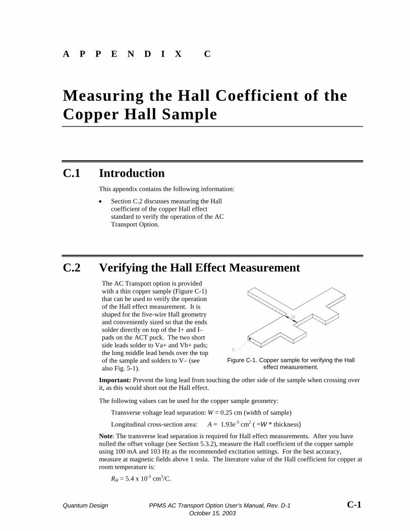
Quantum Design PPMS AC Transport Option User’s Manual, Rev. D-1 C-1 October 15, 2003
A P P E N D I X C
Measuring the Hall Coefficient of the Copper Hall Sample
C.1 Introduction This appendix contains the following information:
• Section C.2 discusses measuring the Hall coefficient of the copper Hall effect standard to verify the operation of the AC Transport Option.
C.2 Verifying the Hall Effect Measurement The AC Transport option is provided with a thin copper sample (Figure C-1) that can be used to verify the operation of the Hall effect measurement. It is shaped for the five-wire Hall geometry and conveniently sized so that the ends solder directly on top of the I+ and I– pads on the ACT puck. The two short side leads solder to Va+ and Vb+ pads; the long middle lead bends over the top of the sample and solders to V– (see also Fig. 5-1).
Figure C-1. Copper sample for verifying the Hall
effect measurement.
Important: Prevent the long lead from touching the other side of the sample when crossing over it, as this would short out the Hall effect.
The following values can be used for the copper sample geometry:
Transverse voltage lead separation: W = 0.25 cm (width of sample)
Longitudinal cross-section area: A = 1.93e-3 cm2 ( =W * thickness)
Note: The transverse lead separation is required for Hall effect measurements. After you have nulled the offset voltage (see Section 5.3.2), measure the Hall coefficient of the copper sample using 100 mA and 103 Hz as the recommended excitation settings. For the best accuracy, measure at magnetic fields above 1 tesla. The literature value of the Hall coefficient for copper at room temperature is:
RH = 5.4 x 10⁻⁵ cm3/C.
Quantum Design PPMS AC Transport Option User’s Manual, Rev. D-1 References-1
References
Quantum Design. 1998. Physical Property Measurement System: Hardware Manual.
⎯⎯⎯. 1999. Physical Property Measurement System: Helium-3 Refrigerator System User’s Manual.
⎯⎯⎯. 1996. Physical Property Measurement System: Horizontal Rotator Option User’s Manual.
⎯⎯⎯. 1998. Physical Property Measurement System: PPMS MultiVu Application User’s Manual.
⎯⎯⎯. 1999. Service note 1070-802, PPMS software and firmware upgrade instructions.

Quantum Design PPMS AC Transport Option User’s Manual, Rev. D-1 Index-1 October 15, 2003
Index
AC bias current range, 1-1 AC board applying gain to signal, 3-3, 3-4 calibrated for specific hardware, 2-2, 3-5 installing, 2-2−2-4 processing signals, 3-5 ACT data files. See Measurement data files; Raw measurement data files ACT/Helium-3 probe cable electrical interconnections, 6-5 installing, 6-2 ACT/Horizontal Rotator probe cable electrical interconnections, 7-5 installing, 7-2 ACT measurements automating, 5-3 data from, saving. See Measurement data files; Raw measurement data files with Helium-3 system, 6-2−6-4 with Horizontal Rotator, 7-1, 7-4 in immediate mode, 5-3−5-11 operating modes, comparing, 5-4 sensitive, avoiding noisy frequencies during, 1-3, 1-5 in sequence mode, 5-12−5-19 types of, 1-1, 1-2, 4-1. See also Critical current measurement; Hall coefficient measurement; I-V curve measurement; Resistivity measurement wiring sample for. See Sample wiring ACT option. See also ACT measurements; ACT software automating operation of, 1-1, 4-1. See also ACT measurements: Sequence mode calibration file, 4-2 electrical connections for, illustration of, 2-6, A-1 hardware. See AC board; ACT sample puck; ACT Y connection cable; Model 7100 AC Transport Controller installation kit, components in, 2-1 installing, 2-2−2-6 measurement types, 1-1, 1-2, 4-1. See also Critical current measurement; Hall coefficient measurement; I-V curve measurement; Resistivity measurement operating with other options. See Helium-3 Refrigerator System option; Horizontal Rotator option pinout tables, A-3, A-5−A-6 providing increased measurement sensitivity, 1-1 sample holders compatible with, 1-1, 3-6, 5-1 software files, 4-1
AC Transport control center commands, executing immediately, 5-3 function, 4-2, 5-3 opening, 2-6, 4-2 tabs in, 4-2−4-6 ACT sample puck connecting solder pads for negative voltage leads, 1-5, 3-6 dual channels on, 3-6, 5-1, 5-3, 5-12 samples correctly wired to, illustration of, 5-1 wiring sample to for Hall measurement, 1-4, 1-5, 5-1−5-2 for resistivity measurement, 1-2−1-3, 5-1−5-2 ACT software. See also AC Transport control center activating in PPMS MultiVu, 2-6 creating data files. See Measurement data files; Raw measurement data files installing, 2-6 integrated into PPMS MultiVu, 1-1, 2-6, 4-1 measuring power line frequency on start-up, 1-6 ACT status log, 4-6, 4-7 ACT Y connection cable in illustration of ACT electrical connections, 2-6, A-1 splitting sample and excitation signals, 3-5 Always autorange gain setting, definition of, 3-3 Anisotropic sample, wiring for resistivity measurement, 1-2 Averaging time, for critical current measurement, 1-7, 5-11 Balance potentiometers adjusting for five-wire Hall measurement, 5-6 for four-wire measurement, 1-5, 5-1, 7-4 function, 3-1, 3-2 Bar-shaped sample, wiring for resistivity measurement, 1-2−1-3 BNC connectors, on Model 7100, 3-1, 3-2 Configure tab, in AC Transport control center, 4-6 Constant Current LED, when lit, 3-2 Constant current mode comparison with low-impedance mode, 3-2 drive source impedance in, 3-3 maintaining current with, 3-2 Critical current, definition of, 1-7 Critical current hard trip parameter, 4-6, 5-11

Index
Index-2 PPMS AC Transport Option User’s Manual, Rev. D-1 Quantum Design October 15, 2003
Critical current measurement description, 1-7, 5-11 in immediate mode, 5-10−5-11 operating modes, 4-1, 5-3 parameters defining, 5-10−5-11 safety voltage limit, 5-11 saving data from, 5-4, 5-10- 5-19 in sequence mode, 5-17−5-19 with superconducting samples, 5-10 as variant of resistivity measurement, 1-2 wiring sample for. See Resistivity measurement: Wiring sample Cross-sectional area, of sample, defining, 4-4, 4-8, 4-9 Current Offset Adjustment potentiometer, 3-4 Data files. See Measurement data files; Raw measurement data files Data file header. See Measurement data files: Header Data File tab, in AC Transport control center, 4-3, 4-8 Diagnostic plots of ACT measurements, examples of, 4-5 Digital filtering, 1-1 Electrical current operating modes. See Constant current mode; Low-impedance mode Electrical interconnections, tables for ACT/Helium-3 probe cable, 6-5 ACT/Horizontal Rotator probe cable, 7-5 ACT system, A-3, A-5−A-6 Electrical transport current measurements. See ACT measurements Error messages listed, B-2−B-3 recorded in ACT status log, 4-7 shown in AC Transport control center, 4-2, B-2 Fixed range gain setting, definition of, 3-3 Gain-ranging mode, for critical current measurement, 5-11 Gain settings, 3-3−3-4 Hall coefficient measurement calculating Hall coefficient, description of, 1-3−1-4, 5-7 comparing four-wire and five-wire, 1-4, 1-5 copper sample, C-1 harmonic detection in, 1-5 operating modes, 4-1, 5-3 parameters defining, 5-6-5-7 sample property information affecting, 4-8, 4-9 saving data from, 5-3, 5-5, 5-8, 5-14 taking five-wire in immediate mode, 5-5−5-7 in sequence mode, 5-12−5-15 varying field to perform highly accurate, 1-4 wiring sample for, on ACT sample puck, 1-4, 1-5, 5-1−5-2. See also Sample wiring: Standard PPMS sample puck
Hall potential, definition of, 1-3 Hardware self-test, 4-6 Helium-3 refrigerator probe, proper handling of, 6-2 Helium-3 Refrigerator System option activating in PPMS MultiVu, 6-3−6-4 current output limit for, 3-3, 6-1, 6-4 extending measurement range, 6-1, 6-4 restricting measurements to single sample, 6-1 taking ACT measurements when installed, 6-2−6-4 using ACT/Helium-3 probe cable, 6-1, 6-2 Helium-3 sample mount, wiring sample to, 6-3 High-impedance mode. See Constant current mode Horizontal Rotator option configuring rotator thermometer for, 7-2−7-3 taking ACT measurements when installed, 7-1, 7-4 using ACT/Horizontal Rotator probe cable, 7-1, 7-2, 7-3 HR###.cfg file, 7-2 HRACT###.cfg file, 7-2, 7-3 Immediate mode, measurements in. See ACT measurements: Immediate mode Installation. See ACT option: Installing Install tab, in AC Transport control center, 4-2, 4-8 I-V curve measurement current versus voltage trace, 1-6 in immediate mode, 5-8−5-10 operating modes, 4-1, 5-3 parameters defining, 5-8−5-10 saving data from, 5-3, 5-8, 5-10, 5-17, 5-19 in sequence mode, 5-16-5-18 time stamp as approximate measurement time, 5-9 as variant of resistivity measurement, 1-2 wiring sample for. See Resistivity measurement: Wiring sample Line averaging time, 5-11 Low-impedance mode comparison with constant current mode, 3-2 disabling I-V curve power limit, 5-8 drive source impedance, determining, 3-3 when useful, 3-2 Masonite blank panel, installing, 2-5 Measure LEDs, on Model 7100, 3-2 Measurement data files creating, 4-9−4-10 header in, information written to, 4-3, 4-4, 4-8, 4-9 identifying selected. See Data File tab storing sample measurement data, 4-3, 4-8 storing system data items, 4-8, 5-4, 5-12 Model 6000 PPMS Controller housing AC board, 3-1, 3-5. See also AC board: Installing in illustration of ACT electrical connections, 2-6, A-1 rear portion of interior, illustration of, 2-4 reporting measurement results, 4-1

Index
Quantum Design PPMS AC Transport Option User’s Manual, Rev. D-1 Index-3 October 15, 2003
Model 7100 AC Transport Controller connections to sample, A-3−A-4 current provided by, 3-2, 5-4, 5-7-5-10 dual measurement channels, 3-2, 3-6, 4-9 electrical current operating modes, comparison of, 3-2 gain settings, 3-3−3-4 in illustration of ACT electrical connections, 2-6, A-1 installing, 2-5 overview of operation, 3-1, 3-2 rear panel ports, function of, A-2 selecting current range for sample excitation, 3-3 thermal cutoff limit, adjusting, 3-4 Output Range LEDs, on Model 7100, 3-3 P1−Sample Current Out port, A-2 P2−Drive Access and Monitor port connections, A-5 function, 2-6, 3-5, A-2 P3−Analog Interface port connections, A-6 function, A-2 P4−Digital Interface port connections, A-6 function, A-2 P5−Sample Signal In port connections, A-3 function, A-2 PPMS MultiVu software application automating ACT operation, 1-1, 4-1, 5-3. See also ACT measurements: Sequence mode installing, 2-6 Preamp Gain LEDs, on Model 7100, 3-3 Raw measurement data files identifying selected. See Data File tab storing raw voltage data, 4-3, 4-8 Raw voltage data, saving, when useful, 4-3 Resistivity measurement description, 1-2−1-3, 5-5 harmonic detection in, 1-3 in immediate mode, 5-3−5-5 operating modes, 4-1, 5-3 parameters defining, 5-5 sample property information affecting, 1-2, 4-8, 4-9 saving data from, 5-3, 5-5, 5-12 in sequence mode, 5-12−5-14 wiring sample for, on ACT sample puck, 1-2−1-3, 5-1−5-2. See also Sample wiring: Standard PPMS sample puck Resistivity option using with ACT option, A-3 using with Horizontal Rotator option, 7-2 Rotator thermometer, connecting to system bridge board, 7-2−7-3
Sample chamber, identifying status of, 4-2 Sample connections, for ACT system, A-3−A-4 Sample mounting. See Sample wiring Sample tabs, in AC Transport control center, 4-3, 4-4 Sample wiring. See also Sample connections on ACT sample puck for Hall measurement, 1-4, 1-5, 5-1−5-2 for resistivity measurement, 1-2−1-3, 5-1−5-2 on Helium-3 sample mount, 6-3 on Horizontal Rotator platform, 7-4 on standard PPMS sample puck, 3-6, 5-2 Sequence mode, measurements in. See ACT measurements: Sequence mode Sticky autorange gain setting, definition of, 3-3 System status, identifying in AC Transport control center, 4-2 in ACT status log, 4-7 Thermal Cutoff Adjustment potentiometer, adjusting, 3-4 UserTemp, turning off, 7-3 Voltage lead separation, of sample, defining, 4-4, 4-8, 4-9 Voltage Limited LED, when lit, 3-3, 3-4 Warning messages listed, B-1 recorded in ACT status log, 4-7 shown in AC Transport control center, 4-2, B-1 Waveform tab, in AC Transport control center, 4-5