physics, measurement trechniques
DESCRIPTION
A lecture on the measurement techniquesTRANSCRIPT
WELCOME
TO
PH:512PH:512
MEASUREMENT
TECHNIQUES
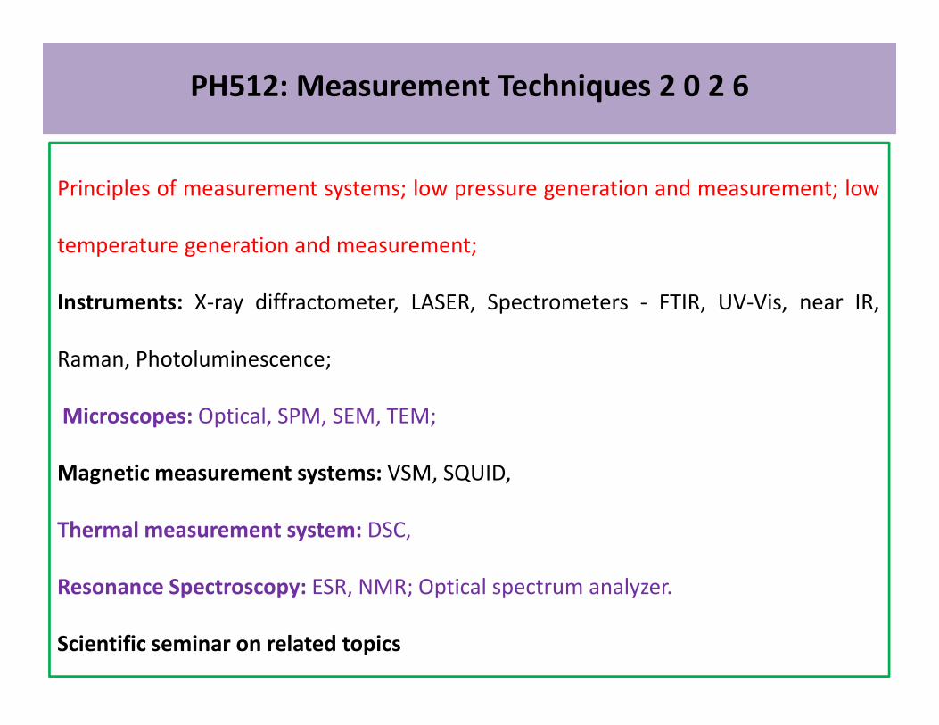
PH512: Measurement Techniques 2 0 2 6
Principles of measurement systems; low pressure generation and measurement; low
temperature generation and measurement;
Instruments: X-ray diffractometer, LASER, Spectrometers - FTIR, UV-Vis, near IR,
Raman, Photoluminescence;Raman, Photoluminescence;
Microscopes: Optical, SPM, SEM, TEM;
Magnetic measurement systems: VSM, SQUID,
Thermal measurement system: DSC,
Resonance Spectroscopy: ESR, NMR; Optical spectrum analyzer.
Scientific seminar on related topics
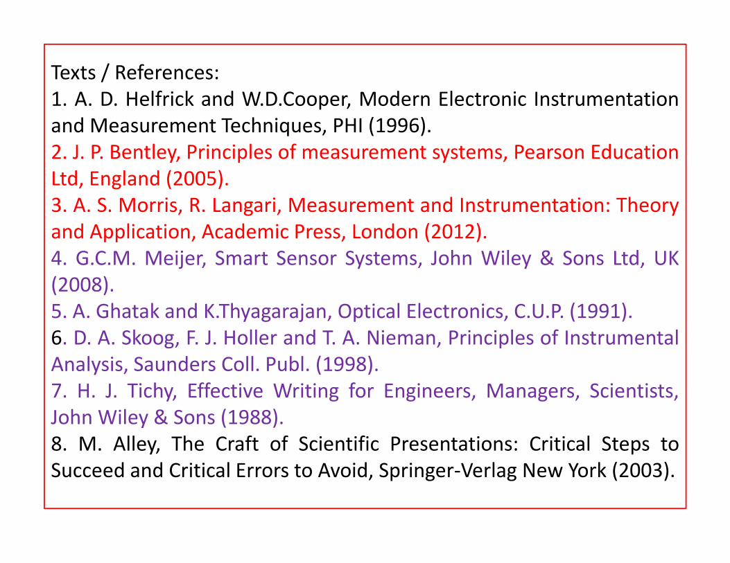
Texts / References:
1. A. D. Helfrick and W.D.Cooper, Modern Electronic Instrumentation
and Measurement Techniques, PHI (1996).
2. J. P. Bentley, Principles of measurement systems, Pearson Education
Ltd, England (2005).
3. A. S. Morris, R. Langari, Measurement and Instrumentation: Theory
and Application, Academic Press, London (2012).
4. G.C.M. Meijer, Smart Sensor Systems, John Wiley & Sons Ltd, UK
(2008).(2008).
5. A. Ghatak and K.Thyagarajan, Optical Electronics, C.U.P. (1991).
6. D. A. Skoog, F. J. Holler and T. A. Nieman, Principles of Instrumental
Analysis, Saunders Coll. Publ. (1998).
7. H. J. Tichy, Effective Writing for Engineers, Managers, Scientists,
John Wiley & Sons (1988).
8. M. Alley, The Craft of Scientific Presentations: Critical Steps to
Succeed and Critical Errors to Avoid, Springer-Verlag New York (2003).
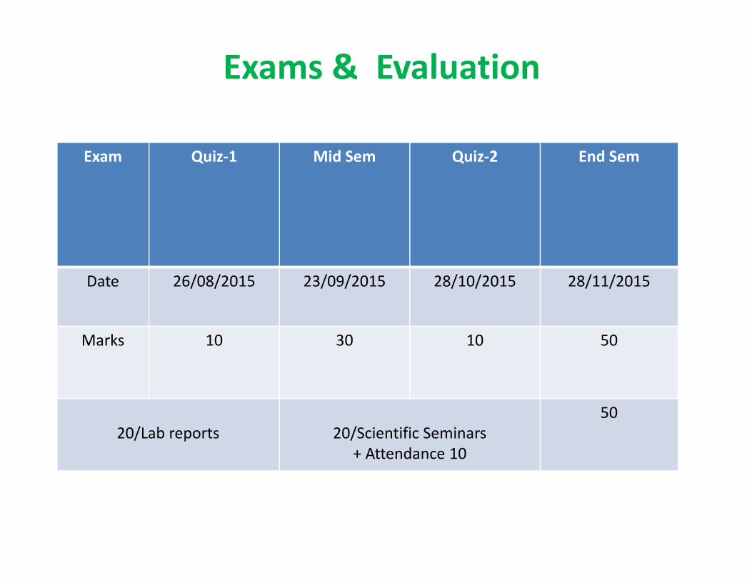
Exam Quiz-1 Mid Sem Quiz-2 End Sem
Date 26/08/2015 23/09/2015 28/10/2015 28/11/2015
Exams & Evaluation
Date 26/08/2015 23/09/2015 28/10/2015 28/11/2015
Marks 10 30 10 50
20/Lab reports 20/Scientific Seminars
+ Attendance 10
50

For the course related information, look in to
https://intranet.iitg.ernet.in/moodle/https://intranet.iitg.ernet.in/moodle/
Use your IITG e-mail user ID and password
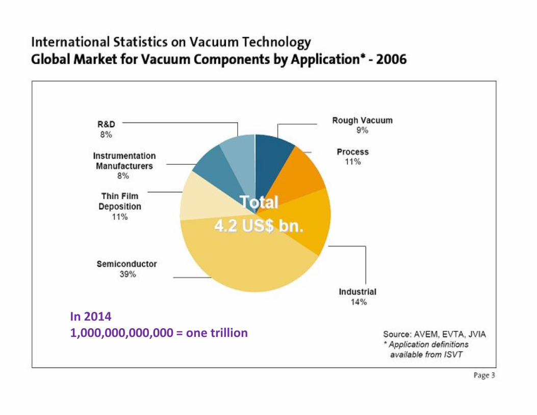
In 2014
1,000,000,000,000 = one trillion
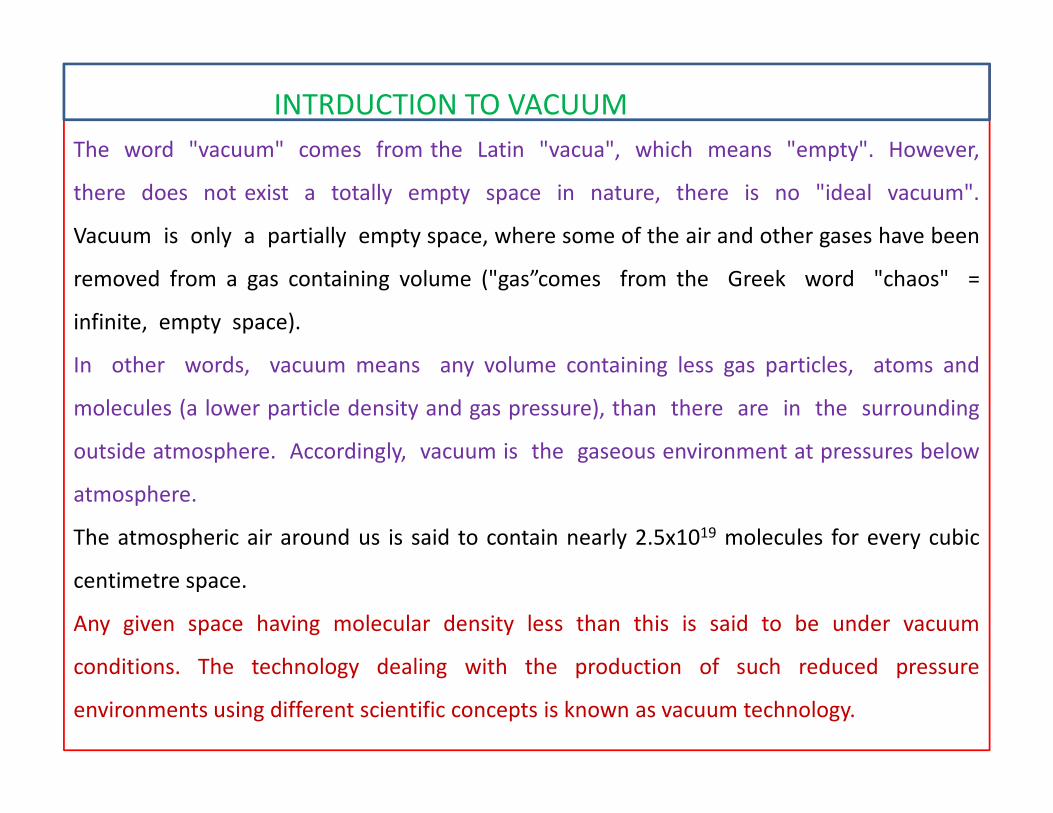
INTRDUCTION TO VACUUM
The word "vacuum" comes from the Latin "vacua", which means "empty". However,
there does not exist a totally empty space in nature, there is no "ideal vacuum".
Vacuum is only a partially empty space, where some of the air and other gases have been
removed from a gas containing volume ("gas”comes from the Greek word "chaos" =
infinite, empty space).
In other words, vacuum means any volume containing less gas particles, atoms and
molecules (a lower particle density and gas pressure), than there are in the surroundingmolecules (a lower particle density and gas pressure), than there are in the surrounding
outside atmosphere. Accordingly, vacuum is the gaseous environment at pressures below
atmosphere.
The atmospheric air around us is said to contain nearly 2.5x10¹⁹ molecules for every cubic
centimetre space.
Any given space having molecular density less than this is said to be under vacuum
conditions. The technology dealing with the production of such reduced pressure
environments using different scientific concepts is known as vacuum technology.
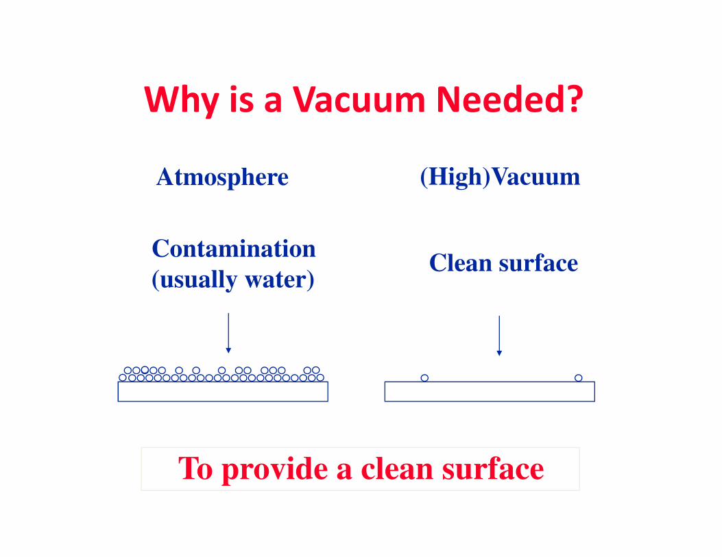
Why is a Vacuum Needed?
Contamination
(usually water)Clean surface
Atmosphere (High)Vacuum
(usually water)
To provide a clean surface
• A vacuum provides a clean environment
– Devoid of possible contamination from other
gases that may be present from the
atmosphere
Why Might We Need Vacuum?
atmosphere
– Devoid of particles that may react with physical
processes that are intended to take place
– Devoid of pressure that may limit restrict a
desired physical process
A vacuum environment provides a “clean slate” for chemical processes. Once the
nitrogen, oxygen, and other gases from the air have been removed from a
vacuum chamber, known amounts of specific gases can be injected into the
chamber for chemical processing to occur.
In the presence of atmospheric gases, the particles of matter present can affect
certain manufacturing and imaging processes
Some physical processes will not occur at acceptable temperatures or will
proceed much more slowly in the presence of atmospheric pressureproceed much more slowly in the presence of atmospheric pressure
The nanotech industry uses various levels of vacuum in the processing,
visualization, and analysis stages of manufacture.
In order to understand how a vacuum system works, it is necessary that the
learner understand the basics of gases and gaseous environments.
Once the basics of gases are understood, an understanding of the operation of
the components that make up a vacuum system such as pumps, gauges, and
materials will follow.
Why do we want to learn about a vacuum?
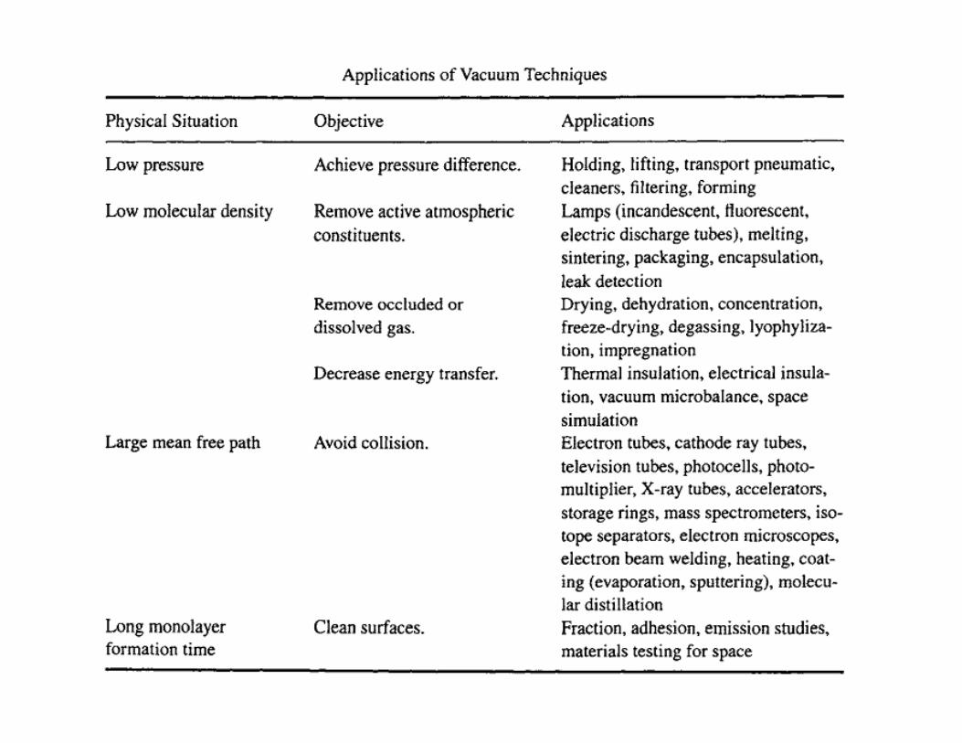
Vacuum technology is widely used in a variety of industries. Here are some applications you would
have certainly heard about:
i) An early application of vacuum technology came around 1900 when the first major industrial use
was for light bulbs and TV tube production (later on). It has been shown that filaments emit
electrons under vacuum which is the major property used in television technology.
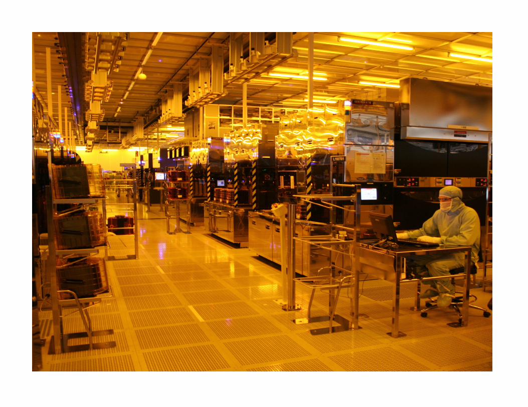
ii) The second major application is in the electronic industry. Many processes that occur in a
semiconductor fabrication facility require vacuums of different levels, including the deposition
of thin films of material on computer chips.
iii) Another major application is in space technology. The main issue in space technology is how to
design the space station or shuttle in order to maintain a pressurized cabin. Also, it is
important to design safe space-suits to protect astronauts during their missions in open space.
These are examples of how vacuum technology helps us. Now we will proceed to learn about
vaccum and how it is created and measured.
Classification of vacuum ranges
Low vacuum (viscous flow) region: The number of gas molecules in the enclosed volume is much
larger compared to the dimensions of a given chamber. While 760 – 0.5 Torr is known as low
vacuum. The mean free path of the gas molecules is very small at atmospheric pressure so that the
flow of the gas is limited by its viscosity.
0.5 to 10-2 Torr is referred to as medium vacuum.
In this range, the mean free path of the molecules is similar to the dimensions of the vacuum
enclosure, the flow of the gas is governed by viscosity as well as by molecular phenomena; this is
the intermediate flow.the intermediate flow.
High vacuum: The gas molecules in the system are located principally on the surfaces as the mean
free path is larger than the characteristic dimensions of the chamber. Particles would freely travel
in the vacuum enclosures colliding more with the walls of the chamber than with other molecules.
The flow of gas under such conditions is molecular. The range extends from 10-3 to 10-7 Torr
Ultra high vacuum: This range covers the pressures from 10-7 to 10-16 Torr. Where the time to
form a monolayer is longer than the usual time for laboratory measurements. Thus clear surface
can be prepared and their properties can be studied. In this range the associated flow is purely
molecular.
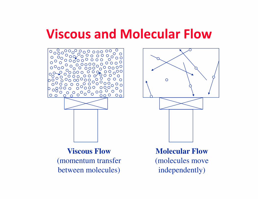
Viscous and Molecular Flow
Viscous Flow
(momentum transfer
between molecules)
Molecular Flow
(molecules move
independently)
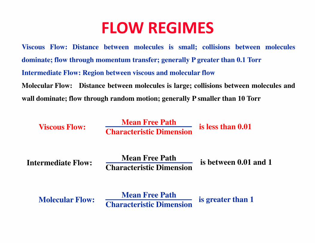
FLOW REGIMESViscous Flow: Distance between molecules is small; collisions between molecules
dominate; flow through momentum transfer; generally P greater than 0.1 Torr
Intermediate Flow: Region between viscous and molecular flow
Molecular Flow: Distance between molecules is large; collisions between molecules and
wall dominate; flow through random motion; generally P smaller than 10 Torr
Mean Free PathMean Free Path
Characteristic DimensionViscous Flow: is less than 0.01
Mean Free Path
Characteristic DimensionMolecular Flow: is greater than 1
Mean Free Path
Characteristic DimensionIntermediate Flow: is between 0.01 and 1
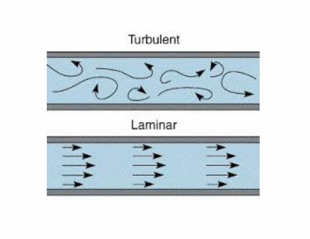
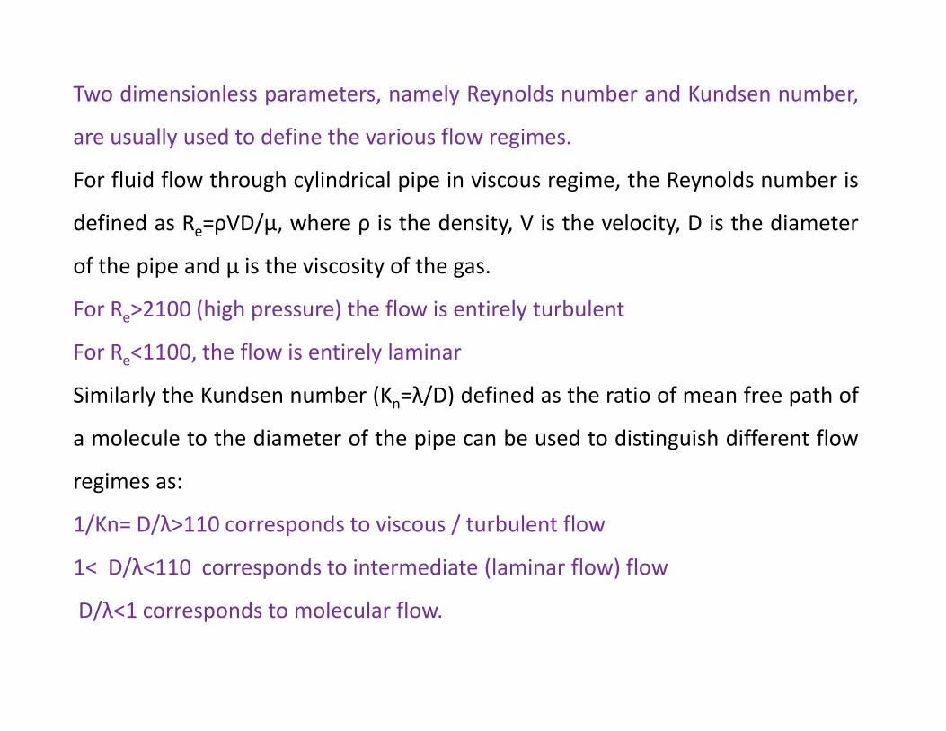
Two dimensionless parameters, namely Reynolds number and Kundsen number,
are usually used to define the various flow regimes.
For fluid flow through cylindrical pipe in viscous regime, the Reynolds number is
defined as Re=ρVD/μ, where ρ is the density, V is the velocity, D is the diameter
of the pipe and μ is the viscosity of the gas.
For Re>2100 (high pressure) the flow is entirely turbulent
For Re<1100, the flow is entirely laminare
Similarly the Kundsen number (Kn=λ/D) defined as the ratio of mean free path of
a molecule to the diameter of the pipe can be used to distinguish different flow
regimes as:
1/Kn= D/λ>110 corresponds to viscous / turbulent flow
1< D/λ<110 corresponds to intermediate (laminar flow) flow
D/λ<1 corresponds to molecular flow.
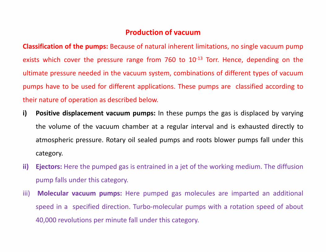
Production of vacuum
Classification of the pumps: Because of natural inherent limitations, no single vacuum pump
exists which cover the pressure range from 760 to 10-13 Torr. Hence, depending on the
ultimate pressure needed in the vacuum system, combinations of different types of vacuum
pumps have to be used for different applications. These pumps are classified according to
their nature of operation as described below.
i) Positive displacement vacuum pumps: In these pumps the gas is displaced by varying
the volume of the vacuum chamber at a regular interval and is exhausted directly tothe volume of the vacuum chamber at a regular interval and is exhausted directly to
atmospheric pressure. Rotary oil sealed pumps and roots blower pumps fall under this
category.
ii) Ejectors: Here the pumped gas is entrained in a jet of the working medium. The diffusion
pump falls under this category.
iii) Molecular vacuum pumps: Here pumped gas molecules are imparted an additional
speed in a specified direction. Turbo-molecular pumps with a rotation speed of about
40,000 revolutions per minute fall under this category.
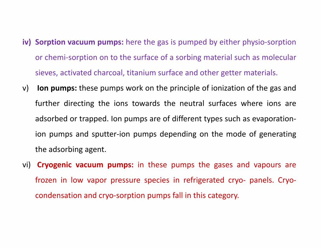
iv) Sorption vacuum pumps: here the gas is pumped by either physio-sorption
or chemi-sorption on to the surface of a sorbing material such as molecular
sieves, activated charcoal, titanium surface and other getter materials.
v) Ion pumps: these pumps work on the principle of ionization of the gas and
further directing the ions towards the neutral surfaces where ions are
adsorbed or trapped. Ion pumps are of different types such as evaporation-
ion pumps and sputter-ion pumps depending on the mode of generating
the adsorbing agent.
vi) Cryogenic vacuum pumps: in these pumps the gases and vapours are
frozen in low vapor pressure species in refrigerated cryo- panels. Cryo-
condensation and cryo-sorption pumps fall in this category.
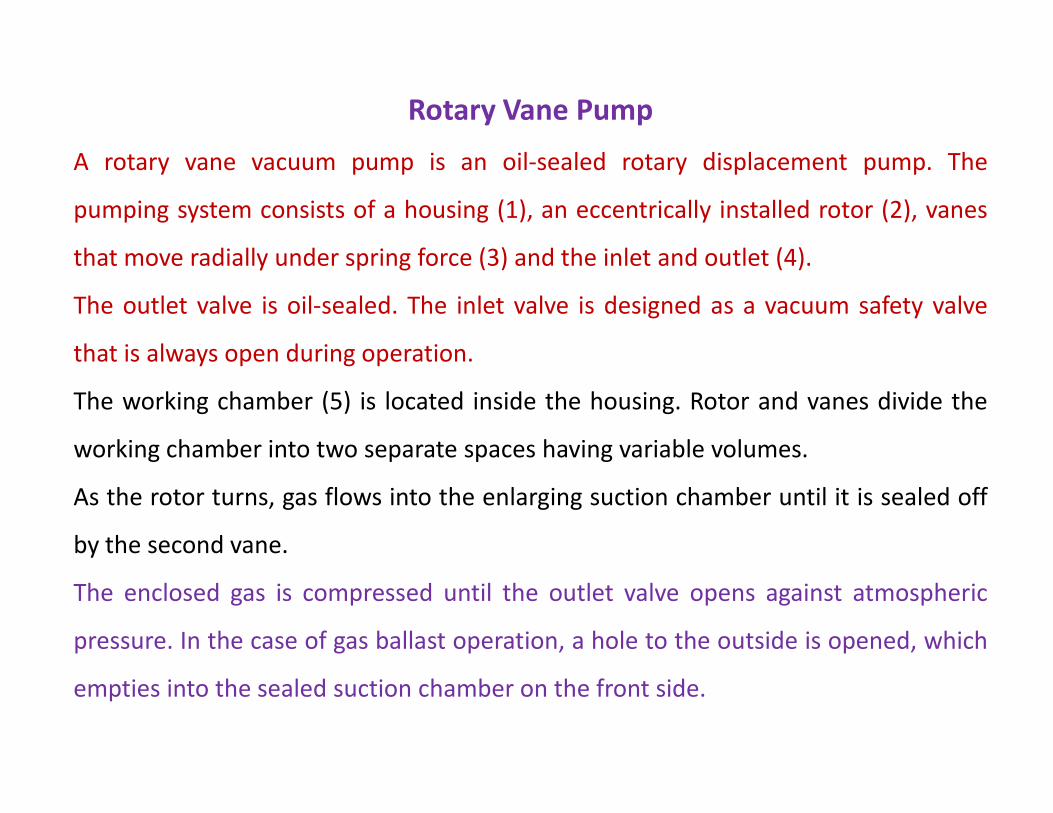
Rotary Vane Pump
A rotary vane vacuum pump is an oil-sealed rotary displacement pump. The
pumping system consists of a housing (1), an eccentrically installed rotor (2), vanes
that move radially under spring force (3) and the inlet and outlet (4).
The outlet valve is oil-sealed. The inlet valve is designed as a vacuum safety valve
that is always open during operation.
The working chamber (5) is located inside the housing. Rotor and vanes divide theThe working chamber (5) is located inside the housing. Rotor and vanes divide the
working chamber into two separate spaces having variable volumes.
As the rotor turns, gas flows into the enlarging suction chamber until it is sealed off
by the second vane.
The enclosed gas is compressed until the outlet valve opens against atmospheric
pressure. In the case of gas ballast operation, a hole to the outside is opened, which
empties into the sealed suction chamber on the front side.
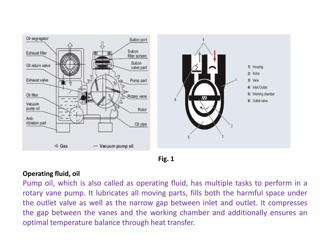
Fig. 1
Operating fluid, oil
Pump oil, which is also called as operating fluid, has multiple tasks to perform in a
rotary vane pump. It lubricates all moving parts, fills both the harmful space under
the outlet valve as well as the narrow gap between inlet and outlet. It compresses
the gap between the vanes and the working chamber and additionally ensures an
optimal temperature balance through heat transfer.
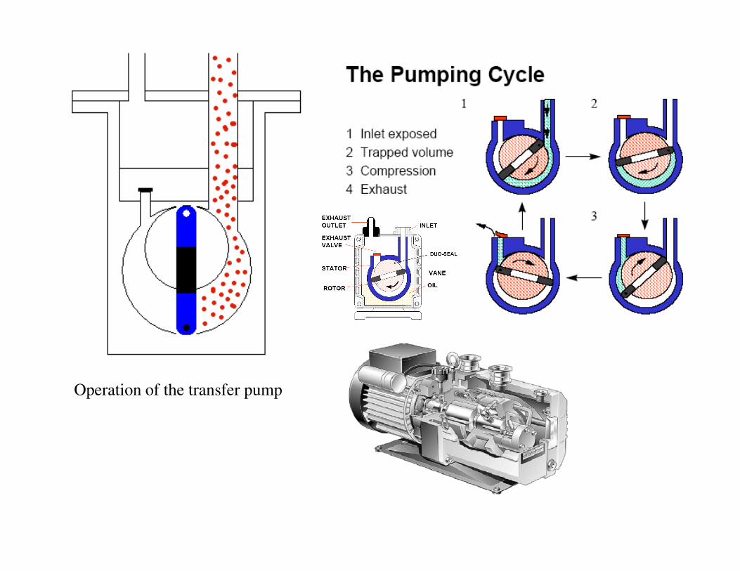
Operation of the transfer pump
Multi-stage pumps
Rotary vane vacuum pumps are built in single- and two-stage versions. Two-stage pumps
achieve lower ultimate pressures than single-stage pumps. Moreover, the effects of the gas
ballast on the ultimate pressure are lower, as the ballast gas is only admitted in the second
stage.
Vacuum safety valve
Depending upon the type of pump in question, rotary vane vacuum pumps can be equipped
with a vacuum safety valve. The vacuum safety valve disconnects the pump from the
vacuum recipient in the event of intentional or unintentional standstill, and uses the
displaced gas to vent the pumping system in order to prevent oil from rising into the
recipient.
After switching on the pump, it opens after a delay once the pressure in the pump has
reached the approximate pressure in the recipient.
These pumps are effective in the range from atmospheric pressure down to 10-3 Torr.
Mechanical pumps are often used as roughing pumps for other types of pumps, like
diffusion pumps.
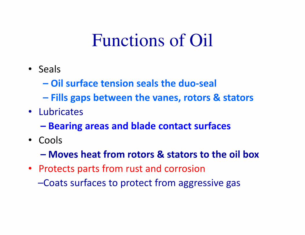
Functions of Oil
• Seals
– Oil surface tension seals the duo-seal
– Fills gaps between the vanes, rotors & stators
• LubricatesLubricates
– Bearing areas and blade contact surfaces
• Cools
– Moves heat from rotors & stators to the oil box
• Protects parts from rust and corrosion
–Coats surfaces to protect from aggressive gas
Diffusion Pumps
Diffusion pumps are vapour jet pumps or vapour ejector pumps designed for pumping
rarefied gases in the high vacuum range (<10-2 Torr) of pressures. These are called the
diffusion pumps because of the fact that the molecules of the pumped gas penetrate the
vapour jet in a manner resembling the diffusion of one gas into another.
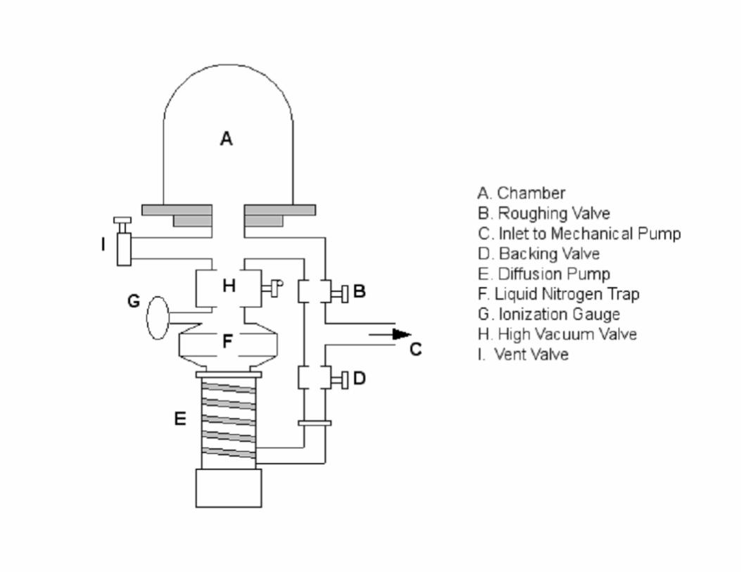
High vacuum systems based on diffusion pumps include at least one diffusion pump and
one rotary pump connected in series. The rotary pump remove about 99.99% of the air
from the chamber. The remaining air and water vapor, down to any pressure from 10-3 to
10-9 Torr is removed by the diffusion pump discharging into the rotary pump.
Diffusion pumps are used when constant high speeds for all gases are desired for long
periods of time without much attention.
Diffusion pumps can not discharge directly into the atmosphere. A rotary pump is required
to reduce the pressure in the vacuum system to the correct operating range. The rotary
pump is then used to maintain proper discharge pressure conditions for the diffusion
pump.
Fig.2 illustrates the working mechanism of a diffusion pump. The arrows represents the pumping fluid
molecules and the small circles represent gas molecules being pumped. A pumping fluid of low vapor
pressure is boiled in the boiler.
The oil vapor flows up through the jet chimneys, reverses its direction at jet caps and emerges out
(downwards) from the nozzles at supersonic velocity.
The oil molecules condense on the pump walls which are water cooled and flow in the form of an oil
film, back down to the boiler where the oil is reboiled and evaporated.
Gas molecules present in the chamber above the jet assembly diffuse into the vapor stream where they
are given a downward momentum due to collisions with heavier oil molecules. Thus the gas moleculesare given a downward momentum due to collisions with heavier oil molecules. Thus the gas molecules
are forced by the jet into a region of higher pressure in the region of lower section of the diffusion pump.
The pressure is high enough for the backing rotary pump to have a finite pumping speed so that
accumulated molecules are drawn off through the for vacuum line.
Diffusion pumps operate only at quiet low pressures. The backing pressure usually required is 10-1 to 10-2
Torr. The ultimate vacuum attainable depends upon the vapor pressure of the pump liquid at
temperature of the condensing surfaces.
However, by providing a cold trap between the diffusion pump and the region being evacuated,
pressures far below the vapor pressure of the liquid may be achieved.
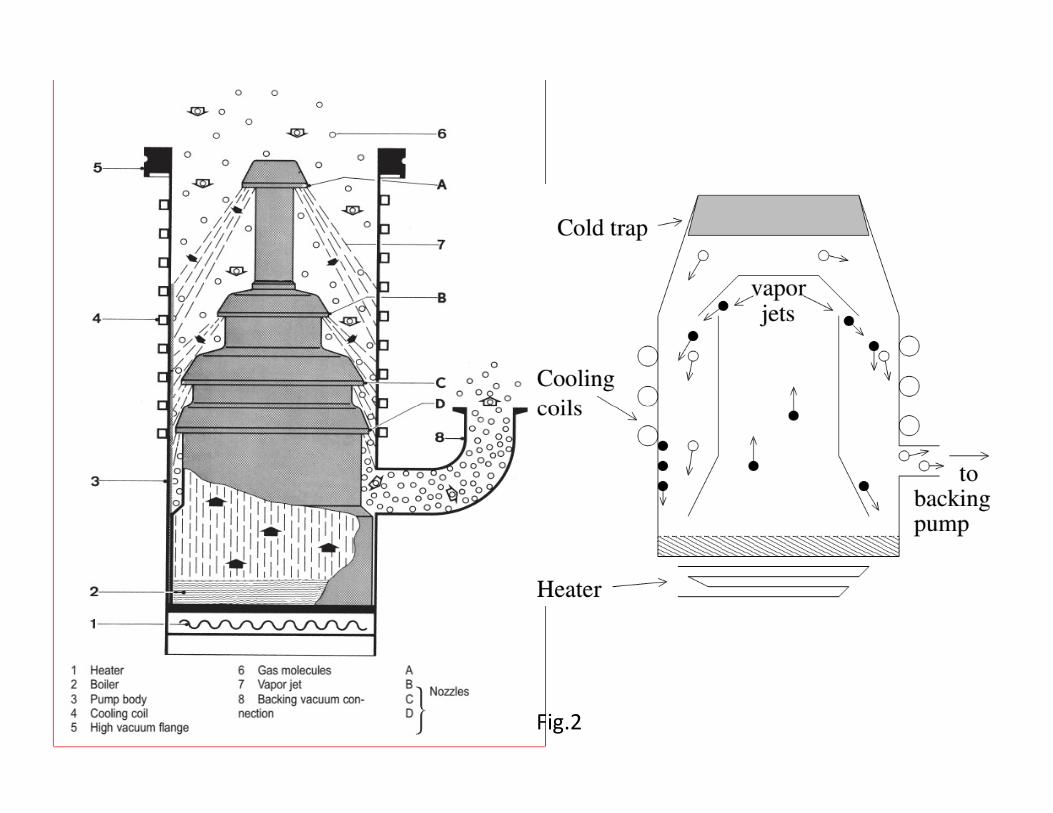
Fig.2
Previously mercury was used as the working fluid.
The advantages of mercury are: it does not decompose and it does not contribute to the
non condensable gas load to the system. Species of unknown molecular weight are not
introduced into the system and hence mass spectrometer analysis is not complicated.
Further, mercury does not react with most other gases or with hot filament.
Some disadvantages: It has smaller molecular weight, less effective as a pump fluid, its
toxic and reacts with metals.
At present silicone oils DC 704 are used due to its high resistance to oxidation atAt present silicone oils DC 704 are used due to its high resistance to oxidation at
elevated temperatures.
Back streaming: The transfer of diffusion pump fluid beyond pump flange mainly
depends on the type of oil and design of the pump. This back streaming can be
minimized by properly designed trap but at the expense of pumping speed. By placing
the LN2 traps above the diffusion pump can improve the performance of the pump in
two ways: This trap acts as a barrier for the low condensible vapors from pump to the
system and also acts for condensible vapors emanating from the system.
The pumping speed of a diffusion pump varies with the pressure for different gases. The
pumping speed for a diffusion pump is constant in its working range and limited by the
pump mouth diameter.
since the mouth diameter determines the number of molecules per second entering the
pump and getting entrained in the supersonic jets.
Diffusion pumps are commercially available with speeds ranging from 100 litrs/ sec to
45,000 litrs/ sec.
The speed of a vapor diffusion pump is higher for light gases such as H and He.The speed of a vapor diffusion pump is higher for light gases such as H and He.
The speed varies inversely with square root of M, where M is the molecular weight of the
gas being pumped.
A simple working formula based on the kinetic theory of gases to get the pumping speed
of a diffusion pump at 20oC for air is given by
S=11.6AH litre/sec where A is the area of the intake annulus (in cm2) around the top jet
cap and H is the Ho-factor whose value is in the range of 0.3 to 0.5.