pilot’s guide kfc 225 bendix/king automatic flight control ... · pdf filepilot’s...
TRANSCRIPT

KFC 225Pilot’s Guide
Bendix/King®
Automatic Flight Control System
006-18035-0000September 2004 N

WARNING
The enclosed technical data is eligible for export under Licanse DesignationNLR and is to be used solely by the individual/organization to whom it isaddressed. Diversion contrary to U.S. law is prohibited.
COPYRIGHT NOTICE
Copyright ©1999, 2004 Honeywell International Inc.All rights reserved.
Reproduction of this publication or any portion thereof by any means withoutthe express written permission of Honeywell International Inc. is prohibited.For further information contact the Manager, Technical Publications;Honeywell; One Technology Center; 23500 West 105th Street; Olathe,Kansas 66061. Telephone: (913) 712-0400.

Revision History and Instructions
Manual KFC 225 AFCS Pilot’s Guide
Revision 1, September 2004
Part Number 006-18035-0000
This revision incorporates a note further explaining the Altitude Holdfunction.
The following pages were changed:
Front Cover, Copyright, 9, 13, Back Cover
R-1

R-2
Revision History and Instructions
Manual KFC 225 AFCS Pilot’s Guide
Revision 0, April 1999
Part Number 006-18035-0000
This is the original version of this publication.

KFC 225 AUTOMATIC FLIGHT CONTROL SYSTEM
Table of Contents
iRev. 0Apr/99
Introduction . . . . . . . . . . . . . . . . . . . . . . . . . . . . . . . . . . . . . . . . . . . . . . . . . . . . .1General Description . . . . . . . . . . . . . . . . . . . . . . . . . . . . . . . . . . . . . . . . . . . . .2System Integration . . . . . . . . . . . . . . . . . . . . . . . . . . . . . . . . . . . . . . . . . . . . . .2Power Application and Preflight Tests . . . . . . . . . . . . . . . . . . . . . . . . . . . . . .4
KFC 225 System Operation . . . . . . . . . . . . . . . . . . . . . . . . . . . . . . . . . . . . . . . .5Controls and Displays Operation . . . . . . . . . . . . . . . . . . . . . . . . . . . . . . . . . . .5Altitude Alerting and Preselect . . . . . . . . . . . . . . . . . . . . . . . . . . . . . . . . . . . .10
Altitude Alerter . . . . . . . . . . . . . . . . . . . . . . . . . . . . . . . . . . . . . . . . . . . . . . .10Altitude Preselect . . . . . . . . . . . . . . . . . . . . . . . . . . . . . . . . . . . . . . . . . . . .10
Voice Messaging . . . . . . . . . . . . . . . . . . . . . . . . . . . . . . . . . . . . . . . . . . . . . .11System Operating Modes . . . . . . . . . . . . . . . . . . . . . . . . . . . . . . . . . . . . . . . .12
Pitch and Roll Attitude Hold (PIT) Modes . . . . . . . . . . . . . . . . . . . . . . . . .12Altitude Hold (ALT) Mode . . . . . . . . . . . . . . . . . . . . . . . . . . . . . . . . . . . . . .13
KFC 225 Detailed System Operation . . . . . . . . . . . . . . . . . . . . . . . . . . . . . . .14Takeoff And Climb To Assigned Altitude . . . . . . . . . . . . . . . . . . . . . . . . . . .14GPS Capture . . . . . . . . . . . . . . . . . . . . . . . . . . . . . . . . . . . . . . . . . . . . . . . .16Outbound On Front Course For Procedure Turn To ILS Approach . . . . . .18Front Course ILS Approach . . . . . . . . . . . . . . . . . . . . . . . . . . . . . . . . . . . .20Outbound on GPS Approach . . . . . . . . . . . . . . . . . . . . . . . . . . . . . . . . . . . .22Inbound on GPS Approach . . . . . . . . . . . . . . . . . . . . . . . . . . . . . . . . . . . . .24
KCS 55A Compass System . . . . . . . . . . . . . . . . . . . . . . . . . . . . . . . . . . . . . . .27KI 525A Indicator . . . . . . . . . . . . . . . . . . . . . . . . . . . . . . . . . . . . . . . . . . . . . .28Description of Indicator and Display Functions . . . . . . . . . . . . . . . . . . . . . . .28Slaving Meter (KA 51B) . . . . . . . . . . . . . . . . . . . . . . . . . . . . . . . . . . . . . . . . .30KMT 112 Magnetic Slaving Transmitter . . . . . . . . . . . . . . . . . . . . . . . . . . . . .31KG 102A Directional Gyro . . . . . . . . . . . . . . . . . . . . . . . . . . . . . . . . . . . . . . .31Abnormal Circumstances . . . . . . . . . . . . . . . . . . . . . . . . . . . . . . . . . . . . . . . .33Flight Procedures with the KCS 55A . . . . . . . . . . . . . . . . . . . . . . . . . . . . . . .34
General Emergency Procedures . . . . . . . . . . . . . . . . . . . . . . . . . . . . . . . . . . .41Autopilot Malfunction . . . . . . . . . . . . . . . . . . . . . . . . . . . . . . . . . . . . . . . . . . .41
Table of Contents
ii KFC 225 AUTOMATIC FLIGHT CONTROL SYSTEMRev. 0Apr/99
This page intentionally left blank

KFC 225 AUTOMATIC FLIGHT CONTROL SYSTEM
Introduction
1Rev. 0Apr/99
Introduction
The pressures of single-pilot instru-ment flying place critical demands onthe skill and concentration of anypilot. To aid you in meeting thesechallenges, Honeywell has devel-oped the KFC 225 Flight ControlSystem. This system places recentflight control advances normallyfound only in high end ‘jet’ autopilotsinto the cockpits of General AviationAircraft.
The heart of the system is alightweight, integrated autopilot com-puter combining the functions ofcomputer, mode selector, altitudepre-selector, and the optional yawdamper into one unit. The systemhas been designed to work withyour Bendix/King equipment fromday one. It can interface directly withyour EFIS system, take roll steeringcommands from your KLN 90B IFRGPS, and, when available, listen toyour KRA 10A radar altimeter toimprove approach tracking.
It is significant that this Silver CrownPlus flight control system has beendesigned from the beginning to inter-face with your Silver Crown Pluspackage of avionics. Consider theadvantage of having your avionicsworking together as an integratedsystem rather than as a group ofunrelated components built by sev-eral different manufacturers.
To fully utilize the impressive capa-bilities of this full-featured system itis important that the pilot understandthe capabilities and limitations of thesystem. The pilot should take timeto read and thoroughly understandthe FLIGHT MANUAL SUPPLE-MENT for the autopilot installationspecific to his aircraft. This Pilot’sGuide should be used to gain addi-tional insight into the operation of thesystem through the specific operat-ing scenarios. The FLIGHT MAN-UAL SUPPLEMENT informationshall always take precedence overthe information found in this manual.

Introduction
2 KFC 225 AUTOMATIC FLIGHT CONTROL SYSTEMRev. 0Apr/99
General Description
The KFC 225 Three Axis system provides lateral, vertical and optional yawmodes with altitude preselect.
GS GS
N33
30W
24
21S
15
12E6
3
ı
NAV HDG
AP
VSARM
G
KFC 225HDG NAV APR REV ALTFD DN
UP
YD
P R
ALT SEL
AIR
ı
DH
2010
1020
1020
2010
AIR
System Integration
The system diagram on the next page shows the components and their rela-tionship in a typical KFC 225 system. The actual components on individualsystems may vary slightly depending on certification and installation require-ments.
The system diagram reflects that the KFC 225 system controls pitch, roll andyaw (optional) axes of the aircraft.

KFC 225 AUTOMATIC FLIGHT CONTROL SYSTEM
Introduction
3Rev. 0Apr/99
KA 285Remote ModeAnnunciator
OR
AIR
ı
DH
20 201010
1020
1020
AIR
KI 256 Attitude Gyro
KS 271CRoll Servo
KS 270CPitch Servo
KS 272C Trim Servo
TRIMFAIL
AP
KCS 55ACompassSystem
ORN
GS GS33
30W
24
21 S15
12E
6
3
ı
NAV HDG
EHI 40EFIS
TST
BRT
NAV
12
HDG
REF
ADF 2
LOC
1
12
CRS 350 4.5
NM
11.5
330°
GS
N33
30W
24
21 S15
12E
6
3
CRS
ARC
HSI
120 KT
KEA 346ServoedAltimeter
KEA 130AEncodingAltimeter
OR
ALT 01
2
3
45
6
7
8
9
29.99MB IN HG
ALT
600500400
0,
B
65101
ENCODING
0 12
34
56
7
89
ALT
Optional KRA 10ARadar Altimeter
System
PU
SH TO TEST
DH 12
3
45101520
25 X 100 FEET
OFF
RADARALTITUDE
50
ıı
OptionalARINC 429
GPS Interface
NAVFPL
MODETRIP
CALCSTAT
SETUPOTHER
NAVD/T
ACTVREFCTR
APTVORNDBINT
SUPL
CRSRCRSR
ALT CLR ENT
PULLSCAN
KLN 90B TSOB GPS
BRT
DMSG
Optional DualControl Wheel Switches
Control Wheel Switches
AircraftStaticPort
KCM 100Configuration
Module
Audio AlertA/P Master Switch
Trim FailAnnunciaor
Remote TerminalI/F Connector
(AFCS Maint. Plug)
KC 225Flight Computer
AP
VSARM
G
KFC 225HDG NAV APR REV ALTFD DN
UP
YD
P R
ALT SEL
HDG
AP
YD
APR
NAV
ARM
GS
REV
ARM
CAP
ALT
ALT
GA
VS
TRIM
KS 271CYaw Servo
KRG 331or
KRG 332Rate Gyro
Optional Yaw Axis
ı
KRG 332
RATE GYRO
KFC 225 System Diagram

Introduction
4 KFC 225 AUTOMATIC FLIGHT CONTROL SYSTEMRev. 0Apr/99
AP
VSARM
G
KFC 225HDG NAV APR REV ALTFD DN
UP
YD
P R
ALT SEL
KFC 225 Preflight Test Complete
AP
VSARM
G
KFC 225HDG NAV APR REV ALTFD DN
UP
YD
P R
ALT SEL
KFC 225 Preflight Test
Power Application and Preflight Tests
A preflight test is performedupon power application to the com-puter. This test is a sequence ofinternal checks that validate propersystem operation prior to allowingautopilot engagement. The preflighttest (PFT) sequence is indicated by“PFT” with an increasing number forthe sequence steps. Successfulcompletion of self test is identified byall display segments being illumi-nated (Display Test), the FlightDirector command bars brought intoview and the disconnect tone sound-ing.
NOTE: Following the preflight test,the red P warning on the face of theautopilot may illuminate indicatingthat the pitch axis cannot beengaged. This condition should betemporary, lasting no more than 30seconds. The P will extinguish andnormal operation will be available.

KFC 225 AUTOMATIC FLIGHT CONTROL SYSTEM
System Operation
5Rev. 0Apr/99
AP
VSARM
G
KFC 225HDG NAV APR REV ALTFD DN
UP
YD
P R
ALT SEL
1
2 4 10
Full KFC 225 Three-Axis with Altitude Preselect Display
11
13 12
5 6 7 8 9
1617 15 1418
3
KFC 225 System Operation
Controls and Displays Operation
1. PITCH AXIS, (P) ANNUNCIA-TOR - When illuminated, indicatesfailure of the pitch axis and will leadto disengagement of the autopilot.(Will also illuminate during short termvertical accelerations in excess of+1.6g or less than +0.4g which maynot cause autopilot disengagement.)
2. ROLL AXIS (R) ANNUNCIA-TOR - When illuminated, indicatesfailure of the roll axis and will disen-gage the autopilot.
3. AUTOPILOT ENGAGE/DISEN-GAGE (AP ) BUTTON - Whenpressed, engages the flight director,autopilot and yaw damper (ifinstalled). If the flight director is notalready engaged, the system willengage into the basic wings level(ROL) and pitch (PIT) attitude holdmodes. The pitch attitude main-tained will be the pitch attitude pre-sent at the moment of AP buttonpress. When pressed again, will dis-engage the autopilot.
4. FLIGHT DIRECTOR (FD)MODE SELECTOR BUTTON –When pressed will engage the flightdirector into the basic roll (ROL)mode which functions as a wing lev-eler, and into the pitch attitude (PIT)hold mode. The pitch attitude main-tained will be the pitch attitude pre-sent at the moment of FD buttonpress. When pressed again (and theautopilot is not engaged) will disen-gage the flight director.
5. HEADING (HDG) MODESELECTOR BUTTON - Whenpressed, will engage the Headingmode, which commands the airplaneto turn to and maintain the headingselected by the heading bug on theHSI. A new heading may beselected at any time and will result inthe airplane turning to the new head-ing. Button can also be used to tog-gle between HDG and ROL modes.This button will engage the flightdirector.

System Operation
6 KFC 225 AUTOMATIC FLIGHT CONTROL SYSTEMRev. 0Apr/99
6. NAVIGATION (NAV ) MODESELECTOR BUTTON - Whenpressed, will arm the navigationmode. If the selected navigation sen-sor is less than 50% deflected whenarmed, the system will automaticallycapture. Otherwise the capture pointwill vary based on needle deflectionand closure rate. The mode providesautomatic beam capture and track-ing of VOR, LOC or GPS asselected for presentation on the HSI.NAV mode is recommended for enroute navigation tracking. If pressedwhen NAV mode is either armed orcoupled, will disengage the mode.This button will engage the flightdirector.
7. APPROACH (APR ) MODESELECTOR BUTTON - Whenpressed, will arm the Approachmode. If the selected navigation sen-sor is less than 50% deflected whenarmed, the system will automaticallycapture. Otherwise the capture pointwill vary based on needle deflectionand closure rate. This mode pro-vides automatic beam capture andtracking of VOR, GPS or LOC withGlideslope (GS) on an ILS, asselected for presentation on the HSI.APR ARM will annunciate. If pressedwhen APR mode is either armed orcoupled, will disengage the mode.This button will engage the flightdirector. (See the NOTE followingitem 8).
8. BACK COURSE APPROACH(REV) MODE SELECTOR BUTTON– (not available when optional ED461 EHSI installed). When pressed,will select the back course approachmode. If the selected navigation sen-
sor is less than 50% deflected whenarmed, the system will automaticallycapture. Otherwise the capture pointwill vary based on needle deflectionand closure rate. This mode func-tions similarly to the approach modeexcept that the autopilot response toLOC signals is reversed and glides-lope is inhibited. This button willengage the flight director.
NOTE: If the optional ED 461EHSI is installed, front and backcourse selection is automatic and isdependent upon the relative differ-ence between the airplane headingand the selected approach course. Ifthe airplane heading differs from theselected course by greater than105°, REV ARM will automaticallyannunciate in anticipation of trackinga localizer back course. If prior tolocalizer capture the headingchanges (ie. during radar vectors ora procedure turn) and falls within105° of the selected course, APRARM will annunciate in anticipationof tracking the localizer front course.
9. ALTITUDE HOLD (ALT) MODESELECT BUTTON - Whenpressed, will engage the AltitudeHold mode. The altitude maintainedis the altitude at the moment the ALTbutton is pressed. If the ALT buttonis pressed with an established climbor descent rate present, there will beapproximately a 10% (of VS rate)overshoot, with the airplane returnedpositively to the selected altitude. Ifpressed when ALT hold mode isengaged, will disengage the mode,defaulting to PIT mode. This buttonwill engage the flight director.

KFC 225 AUTOMATIC FLIGHT CONTROL SYSTEM
System Operation
7Rev. 0Apr/99
10. VERTICAL TRIM (UP/DN) BUT-TONS - The response of these but-tons is dependent upon the verticalmode present when pressed. If PITmode is active, successive buttonpresses will move the pitch attitudehold reference either up or down by0.5° per press, or at the rate of 0.8°per second if held continuously, syn-chronizing the pitch attitude refer-ence to the current pitch attitudeupon release. If VS mode is active,the initial button press will bring upthe commanded vertical speed in thedisplay. Subsequent immediate but-ton presses will increment the verti-cal speed command either up ordown at the rate of 100 ft/min perbutton press, or at the rate ofapproximately 300 ft/min per secondif held continuously. If ALT mode isactive, successive button presseswill move the altitude hold referencealtitude either up or down by 20 feetper press, or if held continuously willcommand the airplane up or down atthe rate of 500 ft/min, synchronizingthe altitude hold reference to theactual airplane altitude upon buttonrelease. (Note that neither the pitchattitude nor the altitude hold refer-ence is displayed. The display willcontinue to show the altitude alerterreference.)
11. ROTARY KNOBS - Used toset the altitude alerter/altitude prese-lect reference altitude. Large (outer)knob changes reference by 1000’sof feet, and the small (inner) knobchanges reference by 100’s of feet.When the flight director is engaged,will automatically arm a preselectaltitude hold capture.
12. VERTICAL SPEED (VS) MODESELECTOR BUTTON – Whenpressed will engage the verticalspeed hold mode. The verticalspeed maintained is the verticalspeed present at the moment the VSbutton is pressed. The vertical speedcommand reference will initially bedisplayed in place of the altitudealert annunciation, defaulting back in3 seconds to the altitude alertervalue. Pressing either the UP or DNbutton will again cause the verticalspeed command reference to be dis-played while causing it to increase ordecrease. When the VS button ispressed again, it will disengage thevertical speed mode. This button willengage the flight director.
13. ALTITUDE ARM (ARM) BUT-TON - When pressed will toggle alti-tude arming on or off. When ALTARM is annunciated, the automaticflight control system will capture thealtitude displayed in the AltitudeAlerter/Vertical Speed Display (pro-vided the aircraft is climbing ordescending to the displayed alti-tude). ALT ARM mode is engagedautomatically whenever the selectedaltitude is changed via the rotaryknobs. Note that the alerter functionsare independent of the arming pro-cess thus providing full time alerting,even when the flight director is dis-engaged. This button will engage theflight director.

System Operation
8 KFC 225 AUTOMATIC FLIGHT CONTROL SYSTEMRev. 0Apr/99
14. SELECTED ALTITUDE/VERTI-CAL SPEED DISPLAY - Normallydisplays the selected altitude. Thedisplay indicates the reference verti-cal speed in FPM for 3 seconds afterthe CWS button or the UP or DNbutton is pressed and the VS modeis engaged.
15. ALTITUDE ALERT (ALERT )ANNUNCIATION - Illuminates as asolid alert in the region from 1000 to200 feet from the selected altitude ifthe airplane was previously outsideof this region. Flashes (1) for twoseconds the first time the airplanecrosses the selected altitude and (2)flashes continuously in the 200 to1000 feet region if the airplane waspreviously inside of this region (i.e.at the selected altitude). An auralalert consisting of five short tones isassociated with the visual alerting.This aural alert occurs 1,000 feetbefore a selected altitude whileapproaching it and 200 feet afterleaving a selected altitude.
16. PITCH TRIM (PT) ANNUNCIA-TION - A flashing PT with anaccompanying arrow head is an indi-cation that the request for auto trimhas lasted longer than 16 seconds.A solid PT without an arrowhead isan indication of a pitch trim fault. Atrim runaway will generate the solidPT annunciation, a remote TRIMFAIL annunciation and a continuousalert tone. Refer to the EMER-GENCY PROCEDURES in the air-plane Flight Manual Supplement forproper response to a pitch trim fault.
17. PITCH AND ROLL MODE,AUTOPILOT AND YAW DAMPERANNUNCIATIONS - Displays theactive flight director pitch modes(PIT, VS, ALT ARM, ALT CAP, ALT,GS ARM, GS, GA, and roll modes(ROL, HDG, NAV ARM, NAV, APRARM, APR, REV ARM, REV).Displays when the autopilot (AP)and yaw damper (YD) are engaged.Also displayed will be a flashing APannunciation (5 seconds) at eachautopilot disconnect accompaniedby an aural tone (for 2 seconds).
18. YAW DAMPER (YD) BUTTON(optional) – When pressed willengage or disengage the yawdamper independent of autopilotoperation. (The yaw damperengages automatically when theautopilot is engaged; however, theyaw damper may then be disen-gaged or reengaged as desired.)
19. AUTOPILOT DISCONNECT(AP DISC/TRIM INTER) SWITCH(not shown) - When pressed willdisengage the autopilot and yawdamper if installed, and interruptelectric trim power. (Located on theleft horn of the pilot’s control wheel.The switch is red in color.) May alsodisengage the flight director depend-ing on how the system is configured.
20. MANUAL ELECTRIC TRIMSWITCHES (not shown) - Whenboth switches are pressed in thesame direction, will activate pitchtrim in the selected direction. If onlyone switch is moved, the trim system

KFC 225 AUTOMATIC FLIGHT CONTROL SYSTEM
System Operation
9Rev. 1Sep/04
will not operate. If one switch fails oris moved and held for 3 seconds, thetrim monitoring system will detect aswitch failure resulting in a PTannunciation on the autopilot displayand the disabling of the electric trimsystem. Use of manual electric trimduring autopilot operation will disen-gage the autopilot. (Located on thepilot’s control wheel.)
21. CONTROL WHEEL STEERING(CWS) MODE BUTTON (not shown)- When pressed and held, disen-gages the pitch, roll, yaw, and pitchtrim clutches allowing the pilot tomaneuver the airplane by hand.Pressing the CWS button will alsosync the automatic flight control sys-tem PIT, ROL, ALT or VS com-mands to the actual attitude, altitudeor vertical speed present at the timethe button is released. It is not rec-ommended to use the CWS for alti-tude changes greater than 400 ft.ROL will maintain wings level if CWSis released at less than 6° bankangle. (Located on the left horn ofthe pilot’s control wheel.)
22. GO AROUND (GA) MODEBUTTON (not shown) – Whenpressed will engage the flight direc-tor in a pitch up attitude and wingslevel (ROL mode). GA will disen-gage the autopilot, and cancel allarmed modes including an armedaltitude preselect. Lateral modessuch as HDG or NAV ARM maysubsequently be added. The autopi-lot may subsequently be engaged.Modification to the commanded pitch
attitude such as through the UP/DNbutton or CWS, etc. will cancel GAand revert to pitch altitude hold.(Located on the engine throttle).
23. OMNI BEARING SELECTKNOB - Selects the desired courseto be tracked by the autopilot(Located on the HSI.)
24. HEADING SELECT KNOB -Positions the heading bug on thecompass card (Located on the HSI.)
25. TRIM FAIL ANNUNCIATOR(not shown) - Illuminates wheneverthe automated preflight self-testdetects a pitch trim fault or a continu-ous monitoring system detects apitch trim fault in flight. (Located onthe instrument panel. The annuncia-tor is red in color.) Refer to theEMERGENCY PROCEDURES inthe airplane Flight ManualSupplement for proper response toa pitch trim fault.

System Operation
10 KFC 225 AUTOMATIC FLIGHT CONTROL SYSTEMRev. 0Apr/99
Altitude Preselect
1. ALTITUDE SELECT knob -ROTATE until selected altitude isdisplayed. ARM annunciationoccurs automatically upon altitudeselection when the flight director isengaged.
2. Airplane - ESTABLISH selectedvertical speed to intercept theselected altitude.
3. Upon altitude capture, ALTARM will extinguish and ALT willbe annunciated.
Note: Glideslope coupling (but notglideslope ARM) will preclude analtitude capture on an ILS.
AP
VSARM
G
KFC 225HDG NAV APR REV ALTFD DN
UP
YD
P R
ALT SEL
AP
VSARM
G
KFC 225HDG NAV APR REV ALTFD DN
UP
YD
P R
ALT SEL
AP
VSARM
G
KFC 225HDG NAV APR REV ALTFD DN
UP
YD
P R
ALT SEL
Altitude Alerter
The function of the Altitude Alerter isindependent of the autopilot.
1. ALTITUDE SELECT knob -ROTATE until the selected altitudeis displayed.
Note: The ALERT annunciation isilluminated 1000 ft. prior to theselected altitude, extinguishes 200 ft.prior to the selected altitude and illu-minates momentarily when theselected altitude is reached. Oncethe selected altitude is reached, aflashing ALERT illumination signifiesthat the 200 ft. “safe band” has beenexceeded and will remain illumi-nated until 1000 ft. from the selectedaltitude. Associated with the visualalerting is an aural alert (five shorttones) which occurs 1000 ft. fromthe selected altitude upon approach-ing the altitude and 200 ft. from theselected altitude on leaving the alti-tude.
Altitude Alerting and Preselect
The Altitude Preselect function allows capturing of a selected altitude andtransferring into altitude hold. Manual input of selected altitude is accom-plished through the rotary knobs on the faceplate of the KFC 225.
The Altitude Alerting function will visually and aurally announce approaching,acquiring and deviation from a selected altitude.
AP
VSARM
G
KFC 225HDG NAV APR REV ALTFD DN
UP
YD
P R
ALT SEL
AP
VSARM
G
KFC 225HDG NAV APR REV ALTFD DN
UP
YD
P R
ALT SEL

KFC 225 AUTOMATIC FLIGHT CONTROL SYSTEM
System Operation
11Rev. 0Apr/99
Voice Messaging
The following standard voice mes-sages will be annunciated as condi-tions warrant:
1. “TRIM IN MOTION, TRIM INMOTION…” - Pitch trim runningfor more than 5 seconds.
2. “CHECK PITCH TRIM” - Anout of trim condition has existedfor 16 seconds.
a. Airplane Control Wheel -GRASP FIRMLY , press CWSand check for an out of pitch trimcondition. Manually retrim asrequired.
b. CWS button - RELEASE .
c. AUTOPILOT OPERATION -CONTINUE if satisfied that theout of trim condition was tempo-rary. DISCONTINUE if evidenceindicates a failure of the auto trimfunction.
The following optional voice mes-sages will be annunciated if the sys-tem is configured for voice messag-ing:
1. “ALTITUDE” - 1000 feetbefore approaching selected alti-tude.
2. “LEAVING ALTITUDE” - 200feet away, departing selected alti-tude.
3. “AUTOPILOT” - Autopilot hasdisengaged, either through pilotaction or automatically.

The ROL mode engages in wingslevel Roll Attitude Hold mode.
To change ROL Attitude Hold Mode:
1. Press CWS and bank the air-craft to the desired bank angle. Ifthe bank angle is less than 6°when the CWS button is released,the autopilot will hold wings level.If the bank angle is greater then 6°when the CWS is released, theautopilot will hold the bank angleup to the maximum allowed by theautopilot for that aircraft.
Vertical Speed (VS) Mode
The Vertical Speed (VS) modeallows vertical speed climbs anddescents. The VS button engagesvertical speed mode.
To operate in the VS mode (withautopilot currently disengaged):
1. VS button - Press. Note ROL,VS and current vertical speed isdisplayed. Pressing the AP buttonwill engage the autopilot in ROLand VS modes.
2. UP or DN button - Selectdesired climb or descent rate.Each button stroke will incrementthe vertical speed commanded upor down by 100 ft/min per buttonpress, or at the rate of approxi-mately 300 ft/min per second ifheld continuously.
System Operation
12 KFC 225 AUTOMATIC FLIGHT CONTROL SYSTEMRev. 0Apr/99
AP
VSARM
G
KFC 225HDG NAV APR REV ALTFD DN
UP
YD
P R
ALT SEL
AP
VSARM
G
KFC 225HDG NAV APR REV ALTFD DN
UP
YD
P R
ALT SEL
Pitch and Roll Attitude Hold(PIT) Modes
The Pitch Attitude Hold (PIT)mode allows constant attitude climbsand descents. The AP or FD buttonengages PIT mode.
To operate in the PIT mode(with autopilot currently disengaged):
1. FD button - Press. Note ROLand PIT are displayed. Pressingthe AP button will engage theautopilot in ROL and PIT modes.
2. UP or DN button - Selectdesired climb or descent attitude.Each button stroke will incrementthe pitch attitude by 0.5°. Pushingand holding the UP or DN buttonwill cause the aircraft to pitch at0.8° per second. Releasing thebutton will sync the attitude to thepresent pitch attitude.
To initiate a climb or descent fromAltitude Hold (ALT) mode:
1. ALT button - Press. Note ALTchanges to PIT referencing thepresent pitch attitude.
2. UP or DN button - Selectdesired climb or descent attitude.Each button stroke will incrementthe pitch attitude by 0.5°.
System Operating Modes

KFC 225 AUTOMATIC FLIGHT CONTROL SYSTEM
System Operation
13Rev. 1Sep/04
AP
VSARM
G
KFC 225HDG NAV APR REV ALTFD DN
UP
YD
P R
ALT SEL
To initiate a climb or descent fromAltitude Hold (ALT) mode:
1. VS button - Press. Note ALTchanges to VS and current verticalspeed is displayed.
2. UP or DN button - Selectdesired climb or descent rate.Each button stroke will change thevertical speed commanded up ordown by 100 ft/min per buttonpress, or at the rate of approxi-mately 300 ft/min per second ifheld continuously.
Note: VS command value will be dis-played during Control WheelSteering (CWS) and for three sec-onds following VS engagement orpressing the UP or DN button. Bothaltitude and vertical speed utilize thesame display area. Altitude is alwaysdisplayed except during verticalspeed selection. If the VS commandvalue is not displayed, pressing (andreleasing) the UP or DN button willnot change the indicated altitude ref-erence but will display the VS com-mand value.
Note: When operating at or near thebest rate of climb airspeed, at climbpower settings, and using verticalspeed hold, it is easy to decelerateto an airspeed where continueddecreases in airspeed will result in areduced rate of climb. Continuedoperation in vertical speed modecan result in a stall. Pitch AttitudeHold may provide better operation atthese airspeeds.
Altitude Hold (ALT) Mode
The Altitude Hold (ALT ) modemaintains the pressure altitudeacquired upon selection of altitudehold. The ALT button togglesbetween altitude hold and pitch atti-tude hold modes.
To operate in the ALT mode:
1. ALT button - Press. Note ALTis annunciated and autopilotmaneuvers to maintain pressurealtitude acquired at button selec-tion.
2. UP or DN button - Select tochange altitude. Button strokes willmove the reference altitude by 20feet per press, or if held continu-ously will command a 500 ft/minaltitude change, acquiring a newreference altitude upon buttonrelease.
Note: The system incorporates auto-matic Baro correction capability. Anychange in Baro setting will be com-pensated for by the autopilot to con-tinue holding the reference altitude.
Note: When altitude hold is engagedand holding an altitude, and the APbutton is depressed to disengage theAP, the system defaults to FD andALT hold. If an altitude change ismade up or down the Altitude modemust be cycled off then back on, bycycling the ALT button. If the ALTmode is not cycled and the AP isreengaged, the AP will seek the pre-viously selected altitude.
Detailed System Operation
14 KFC 225 AUTOMATIC FLIGHT CONTROL SYSTEMRev. 0Apr/99 KFC 225 AUTOMATIC FLIGHT CONTROL SYSTEM
Detailed System Operation
15Rev. 0Apr/99
GS GS
ı
NAV HDG
AP
VSARM
G
KFC 225HDG NAV APR REV ALTFD DN
UP
YD
P R
ALT SEL
N
3330
W
24 21S
1512
E
63
AIR
ı
DH
2010
1020
1020
2010
AIR
GS GS
ı
NAV HDGN33
30W
24
21 S15
12E
6
3
AP
VSARM
G
KFC 225HDG NAV APR REV ALTFD DN
UP
YD
P R
ALT SEL
AIR
ı
DH
2010
1020
1020
2010
AIR
N
080°
010°
1 2 3 4
1 2 3 4
GS GS
ı
NAV HDG
AP
VSARM
G
KFC 225HDG NAV APR REV ALTFD DN
UP
YD
P R
ALT SEL
N33
30W 24
21S
15
12E6
3
AIR
ı
DH
2010
1020
1020
2010
AIR
GS GS
ı
NAV HDG
AP
VSARM
G
KFC 225HDG NAV APR REV ALTFD DN
UP
YD
P R
ALT SEL
N33
30W 24
21S
15
12E6
3
AIR
ı
DH
2010
1020
1020
2010
AIR
KFC 225 Detailed System Operation
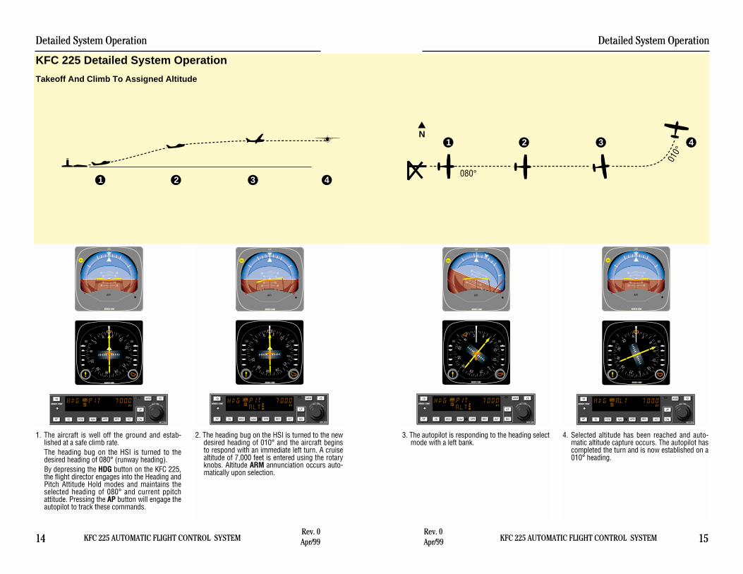
Takeoff And Climb To Assigned Altitude
3. The autopilot is responding to the heading selectmode with a left bank.
4. Selected altitude has been reached and auto-matic altitude capture occurs. The autopilot hascompleted the turn and is now established on a010° heading.
1. The aircraft is well off the ground and estab-lished at a safe climb rate.The heading bug on the HSI is turned to thedesired heading of 080° (runway heading).By depressing the HDG button on the KFC 225,the flight director engages into the Heading andPitch Attitude Hold modes and maintains theselected heading of 080° and current ppitchattitude. Pressing the AP button will engage theautopilot to track these commands.
2. The heading bug on the HSI is turned to the newdesired heading of 010° and the aircraft beginsto respond with an immediate left turn. A cruisealtitude of 7,000 feet is entered using the rotaryknobs. Altitude ARM annunciation occurs auto-matically upon selection.

KFC 225 AUTOMATIC FLIGHT CONTROL SYSTEM
Detailed System Operation
17Rev. 0Apr/99
Detailed System Operation
16 KFC 225 AUTOMATIC FLIGHT CONTROL SYSTEMRev. 0Apr/99
N
1
2
3
4
40°
010°
3. When the computed capture point is reached,the HDG annunciation changes to NAV and aright turn is initiated by the autopilot.
4. The turn is complete and the autopilot is track-ing the GPS course.
1. Continuing on heading 010°, a GPS waypoint isestablished. A 30° intercept is desired.
2. GPS data is selected for the HSI. The coursepointer is set to 040°. The NAV button isdepressed and NAV ARM is annunciated.
GPS Capture
GS GS
ı
NAV HDG
AP
VSARM
G
KFC 225HDG NAV APR REV ALTFD DN
UP
YD
P R
ALT SEL
N33
30W
24
21 S15
12E
6
3
AIR
ı
DH
2010
1020
1020
2010
AIR
GS GS
ı
NAV HDG
AP
VSARM
G
KFC 225HDG NAV APR REV ALTFD DN
UP
YD
P R
ALT SEL
N33
30W
24
21 S15
12E
6
3
AIR
ı
DH
2010
1020
1020
2010
AIR
GS GS
ı
NAV HDG
AP
VSARM
G
KFC 225HDG NAV APR REV ALTFD DN
UP
YD
P R
ALT SEL
N
3330
W
24 21S
1512
E
63
AIR
ı
DH
2010
10
20
1020
20
10
AIR
GS GS
ı
NAV HDG
AP
VSARM
G
KFC 225HDG NAV APR REV ALTFD DN
UP
YD
P R
ALT SEL
N
3330
W
24 21S
1512
E
63
AIR
ı
DH
2010
1020
1020
2010
AIR
* Description of GPS operation based on Bendix/King GPS receiver. Others mayrequire different operation.

Detailed System Operation
18 KFC 225 AUTOMATIC FLIGHT CONTROL SYSTEMRev. 0Apr/99 KFC 225 AUTOMATIC FLIGHT CONTROL SYSTEM
Detailed System Operation
19Rev. 0Apr/99
3. At the desired point, HDG mode is used to initi-ate the procedure turn. During the procedureturn outbound, the deviation bar shows that theaircraft is flying away from the localizer center-line at a 45° angle on a selected heading of283°.
4. Now you have reset the heading bug to 103°and made a 180° turn to this heading. The103° heading will intercept the front course of058°. You must now select the approach modeby depressing the APR button on the KFC 225.Automatic capture of the localizer will occur.
N
33
30W24
21S
15
12 E6
3
GS GS
ı
NAV HDG
AP
VSARM
G
KFC 225HDG NAV APR REV ALTFD DN
UP
YD
P R
ALT SEL
AIR
ı
DH
2010
1020
1020
2010
AIR
N
33
30 W24
21S
15
12E6
3
GS GS
ı
NAV HDG
AP
VSARM
G
KFC 225HDG NAV APR REV ALTFD DN
UP
YD
P R
ALT SEL
AIR
ı
DH
2010
1020
1020
2010
AIR
N1
23
4
270°
058°
238°
283°
103°
1. The aircraft is heading 270° with heading andaltitude hold engaged. To intercept and fly theILS front course outbound, set the front courseon the HSI and depress the back course (REV)button. The back course (REV) mode isselected to go outbound on the front course.The capture point is now being computedbased on closure rate.
2. When the computed capture point is reached,HDG mode is cancelled and reverse localizermode is automatically activated and a left turnoutbound on the localizer is initiated by theautopilot.
Note: The left-right deviations of the HSI courseneedle operate just as though you were flying afront course approach.
Outbound On Front Course For Procedure Turn To ILS Approach
GS GS
ı
NAV HDG
N33
30W24
21S
15
12 E6
3
AP
VSARM
G
KFC 225HDG NAV APR REV ALTFD DN
UP
YD
P R
ALT SEL
AIR
ı
DH
2010
1020
1020
2010
AIR
GS GS
ı
NAV HDG
N33
30
W2421
S15
12
E 63
AP
VSARM
G
KFC 225HDG NAV APR REV ALTFD DN
UP
YD
P R
ALT SEL
AIR
ı
DH
2010
1020
1020
2010
AIR

Detailed System Operation
20 KFC 225 AUTOMATIC FLIGHT CONTROL SYSTEMRev. 0Apr/99 KFC 225 AUTOMATIC FLIGHT CONTROL SYSTEM
Detailed System Operation
21Rev. 0Apr/99
3. At the middle marker, the pilot disengages theautopilot for landing, or may press the Go-Around button, also disengaging the autopilot toinitiate a missed approach. This cancels APRand GS modes and engages the Flight Directorin ROL (wings level) and GA (Pitch AttitudeHold) at GA pitch angle. A flashing AP is dis-played and a disconnect tone is heard.
4. The pilot may now re-engage the autopilot.Press HDG to engage the heading mode to flythe missed approach. Press CWS and pitch theaircraft to obtain best climb. This will sync thecommand bars and change the annunciation toPIT from GA. Finally, pressing the ARM buttonwill arm the selected altitude.
GS GS
ı
NAV HDG
N33
30
W 2421
S15
12
E63
AIR
ı
DH
2010
1020
1020
2010
AP
VSARM
G
KFC 225HDG NAV APR REV ALTFD DN
UP
YD
P R
ALT SEL
N33
30 W24
21S
15
12E6
3
GS GS
ı
NAV HDG
AP
VSARM
G
KFC 225HDG NAV APR REV ALTFD DN
UP
YD
P R
ALT SEL
AIR
ı
DH
2010
1020
1020
2010
AIR
N
12
3
4
058°
090°
238°
1. Continuing the Front Course for Procedure Turnto ILS Approach maneuver, APR couplingoccurs (HDG annunciation changes to APR),and the glideslope mode is automaticallyarmed. The autopilot will capture the localizerand the CDI course index will center.
2. The autopilot is following the localizer. At theouter marker, the glideslope deviation needle isat midscale. Altitude hold is automatically disen-gaged when the glideslope is captured. The ALTannunciation extinguishes and GS is displayed.The autopilot will make pitch and bank changesas necessary to maintain localizer and glides-lope.
GS GS
ı
NAV HDG
N33
30
W 2421
S15
12
E63
AP
VSARM
G
KFC 225HDG NAV APR REV ALTFD DN
UP
YD
P R
ALT SEL
AIR
ı
DH
2010
1020
1020
2010
AIR
N33
30
W 2421
S15
12
E63
GS GS
ı
NAV HDG
AP
VSARM
G
KFC 225HDG NAV APR REV ALTFD DN
UP
YD
P R
ALT SEL
AIR
ı
DH
2010
1020
1020
2010
AIR
1 2 3 4
Front Course ILS Approach

KFC 225 AUTOMATIC FLIGHT CONTROL SYSTEM
Detailed System Operation
23Rev. 0Apr/99
Detailed System Operation
22 KFC 225 AUTOMATIC FLIGHT CONTROL SYSTEMRev. 0Apr/99
3. At the desired point, heading mode is used toinitiate the procedure turn. During the procedureturn outbound, the deviation bar shows that theaircraft is flying away from the GPS course at a45° angle on a selected heading of 283°.
4. The heading bug has been set to 103° and theaircraft has made a left turn to this heading.The GPS’s Leg/OBS mode switching is set toLeg mode and the course pointer is set to058°. Select approach mode by depressing theAPR button.
1. The aircraft is in APR mode approaching theIAF. Approach arm is indicated on the GPSannunciator.*
2. Upon waypoint alerting at the IAF, the coursepointer is set to 238°, the GPS’s Leg/OBS modeswitching is set to OBS mode. The autopilot ini-tiates a left turn to track the 238° GPS course.
N33
30W24
21S
15
12 E6
3
GS GS
ı
NAV HDG
AP
VSARM
G
KFC 225HDG NAV APR REV ALTFD DN
UP
YD
P R
ALT SEL
AIR
ı
DH
2010
1020
1020
2010
AIR
N33
30
W2421
S15
12
E 63
GS GS
ı
NAV HDG
AP
VSARM
G
KFC 225HDG NAV APR REV ALTFD DN
UP
YD
P R
ALT SEL
AIR
ı
DH
2010
1020
1020
2010
AIR
N
33
30W24
21S
15
12 E6
3
GS GS
ı
NAV HDG
AP
VSARM
G
KFC 225HDG NAV APR REV ALTFD DN
UP
YD
P R
ALT SEL
AIR
ı
DH
2010
1020
1020
2010
AIR
N
33
30 W24
21S
15
12E6
3
GS GS
ı
NAV HDG
AP
VSARM
G
KFC 225HDG NAV APR REV ALTFD DN
UP
YD
P R
ALT SEL
AIR
ı
DH
2010
1020
1020
2010
AIR
N
12
3
4
058°
270°
238°
283°
103°
Outbound on GPS Approach
* Description of GPS operation based on Bendix/King GPS receiver. Others mayrequire different operation.

KFC 225 AUTOMATIC FLIGHT CONTROL SYSTEM
Detailed System Operation
25Rev. 0Apr/99
Detailed System Operation
24 KFC 225 AUTOMATIC FLIGHT CONTROL SYSTEMRev. 0Apr/99
N
1
2
3
4
058°
090°
238°
FAF
3. Autopilot operation is not recommended for leveloff at MDA. After level off, autopilot operation inAPR or ALT modes may be resumed if desired.Disengage the autopilot for landing.
4. At the MAP, the pilot may press the Go-Aroundbutton, disengaging the autopilot to initiate amissed approach. This cancels APR and ALTmodes and engages the flight director in ROL(wings level) and PIT (Pitch Attitude Hold) atGA pitch angle. A flashing AP is displayed anda disconnect tone is heard. The pilot stabilizesthe aircraft in the climb and then may re-engage the autopilot.
1. Continuing the Outbound on GPS Approachmaneuver, APR mode capture occurs. Theautopilot initiates a left turn to track the 058°GPS course.
* Approach active is indicated on the GPS annun-ciator.
2. At the FAF, VS is depressed to activate verticalspeed mode. The desired descent rate isobtained using the DN button. Remember, speed needs to be controlled withthe throttle.
Inbound on GPS Approach
* Description of GPS operation based on Bendix/King GPS receiver. Others mayrequire different operation.
1 2
3 4
N33
30W 24
21S
15
12E6
3GS GS
ı
NAV HDG
AP
VSARM
G
KFC 225HDG NAV APR REV ALTFD DN
UP
YD
P R
ALT SEL
AIR
ı
DH
2010
1020
1020
2010
AIR
N33
30
W 2421
S15
12
E63
GS GS
ı
NAV HDG
AP
VSARM
G
KFC 225HDG NAV APR REV ALTFD DN
UP
YD
P R
ALT SEL
AIR
ı
DH
2010
1020
1020
2010
AIR
N33
30
W 2421
S15
12
E63
GS GS
ı
NAV HDG
AP
VSARM
G
KFC 225HDG NAV APR REV ALTFD DN
UP
YD
P R
ALT SEL
AIR
ı
DH
2010
1020
1020
2010
AIR
N33
30 W24
21S
15
12E6
3
GS GS
ı
NAV HDG
AP
VSARM
G
KFC 225HDG NAV APR REV ALTFD DN
UP
YD
P R
ALT SEL
AIR
ı
DH
2010
1020
1020
2010
AIR

Detailed System Operation
26 KFC 225 AUTOMATIC FLIGHT CONTROL SYSTEMRev. 0Apr/99
This page intentionally left blank

KFC 225 AUTOMATIC FLIGHT CONTROL SYSTEM
KCS 55A Compass System
27Rev. 0Apr/99
KCS 55A CompassSystem
The KCS 55A CompassSystem, which includes the KA 51BSlaving Control and CompensatorUnit, the KMT 112 Magnetic SlavingTransmitter and the KG 102Directional Gyro as well as the KI525A Pictorial Navigation Indicator isan optional part of the KFC 225Flight Control System.
The panel-mounted KI 525AHSI combines the display functionsof both the standard Directional Gyroand the Course Deviation Indicator’sVOR/LOC/Glideslope information toprovide the pilot with a single pre-sentation of the complete horizontalnavigation situation. This greatlysimplifies course orientation, inter-ception and tracking, while eliminat-ing the need for scan coordinationbetween two separate indicators.
NGS GS33
30W
2421 S
15
12E
6
3
ı
NAV HDG
ı
KCS 305
KMT 112
KI 525A
KG 102A
MAN
CW
AUTO
CCW
- +
KA 51B
KCS 55A Compass System

KCS 55A Compass System
28 KFC 225 AUTOMATIC FLIGHT CONTROL SYSTEMRev. 0Apr/99
KI 525A Indicator
The KI 525A PictorialNavigation Indicator is the panel dis-play for the KCS 55A CompassSystem. It replaces the standardDirectional Gyro and CourseDeviation Indicator (CDI) in the air-craft’s panel, combining slaved
heading and VOR/LOC/Glideslopeinformation into one compact dis-play. By providing a simple, compre-hensive visual presentation of theaircraft’s heading and position inrelation to a desired course, thepilot’s navigation workload is consid-erably reduced.
NGS GS
33
30W
24
21 S15
12E
6
3
ı
NAV HDG
NAV warningFlag
Lubber Line CompassWarning Flag
Heading Select Bug
Dual GlideslopePointers
Symbolic Aircraft
VOR and LOCDeviation Bar
Course Select Knob VOR/LOC
Deviation ScaleCompass Card
Heading Select Knob
GlideslopeDeviation Scale
To-FromIndicator
CourseSelectPointer
KI 525A Pictorial Navigation Indicator
Description of Indicator andDisplay Functions
Compass Card - Responding to theinput from the slaved directionalgyro, this card rotates within the dis-play so that the aircraft heading isalways at the top, under the lubberline.
Lubber Line - A fixed white markerat the top of the display that indi-cates aircraft magnetic heading onthe compass card.
Symbolic Aircraft - A fixed repre-sentation of the actual aircraft. Thisminiature aircraft always pointstoward the top of the display and thelubber line.

KFC 225 AUTOMATIC FLIGHT CONTROL SYSTEM
KCS 55A Compass System
29Rev. 0Apr/99
Selected Course Pointer - On thistwo-part arrow, the “head” indicatesthe desired VOR or Localizer courseand the “tail” indicates the reciprocal.This pointer is set by rotating thecourse select knob.
Course Select Knob - Used torotate the course pointer to thedesired course on the compasscard. This knob corresponds to theOmni Bearing Selector (OBS) onstandard NAV indicators.
VOR/RNAV and LOC Deviation -This bar corresponds to the“left/right” needle on standard coursedeviation indicators. When the air-craft is precisely on the VOR radialor Localizer course, it forms the cen-ter section of the selected coursepointer and will be positioned underthe symbolic aircraft. When offcourse or approaching a newcourse, it will move to one side orthe other. Since the entire VOR andLocalizer display rotates with thecompass card, the angular relation-ship between the deviation bar andthe symbolic aircraft provides a pic-torial symbolic display of the air-craft’s position with respect to theselected course.
Deviation Scale - When tuned to aVOR frequency, each white dot rep-resents two degrees of deviation leftor right of course. When tuned to aLocalizer, the deviation is 1/2 degreeper dot. (When GPS data is selectedfor presentation, refer to the Pilot’sGuide for the GPS receiver.)
Heading Select Bug - A movableorange marker on the outer perime-ter of the display, used primarily toselect the desired heading you wishto fly. This desired heading is cou-pled to the KFC 225 Flight controlsystem to provide the “HeadingSelect” function.
Heading Select Knob - Used torotate the heading select bug to adesired point on the compass card.
To-From Indicator - A white trianglenear the center of the display thatindicates, with reference to the OBSsetting, whether the course selectedis “to” or “from” the selected VORstation and/or RNAV waypoint.
Dual Glideslope Pointers -Chartreuse triangular pointers oneither side of the display drop intoview when a usable glideslope sig-nal is received and retract out ofview when the glideslope signalbecomes marginal. During an ILSapproach, these pointers representthe vertical orientation of the aircraftwith respect to the center of theglideslope beam. When on glides-lope, the pointers will align with thecenter markers on the glideslopescale.
Glideslope Deviation Scale - Whitedots on each side of the displaywhich, in conjunction with the glides-lope pointers, indicate either“above”, “below”, or “on glideslope”during an ILS approach.

KCS 55A Compass System
30 KFC 225 AUTOMATIC FLIGHT CONTROL SYSTEMRev. 0Apr/99
Compass Warning Flag - A red flaglabeled “HDG” becomes visible inthe upper right quadrant of the dis-play whenever the electrical power isinadequate or the directional gyro isnot up to speed. Compass failurescan occur which will not be annunci-ated by the “HDG” flag. Therefore,periodic comparison with thestandby compass is advised.
NAV Warning Flag - A red flaglabeled “NAV” becomes visible in theupper left quadrant of the displaywhenever a usable signal is notbeing received.
Slaving Meter (KA 51B)
This meter indicates any differ-ence between the displayed headingand the magnetic heading. Right orup deflection indicates a clockwiseerror of the compass card. Left ordown deflection indicates a counter-clockwise error of the compass card.Whenever the aircraft is in a turn andthe card rotates, it is normal for thismeter to show a full deflection to oneside or another.
NOTE: During level flight it is normalfor the meter needle to continuouslymove from side to side and to befully deflected during a turn. If theneedle stays fully deflected, left orright, during level flight, the free gyromode can be used to center it, asfollows:
Slave and Free Gyro Switch - Whenthe switch is in the AUTO position,the system is in the slaved gyromode. When the switch is in theMAN position, the system is in thefree gyro mode.
Clockwise Adjustment - When thesystem is in the free gyro mode,holding the manual heading switchto the CW position will rotate thecompass card to the right to elimi-nate left compass card error.
Counterclockwise Adjustment -When the system is in the free gyromode, holding the manual headingswitch to the CW position will rotatethe compass card to the left to elimi-nate right compass card error.
The KA 51B Slaving Controland Compensator Unit is a smallslaving accessory which can beused in installations where panelspace is limited. The KA 51B can bemounted either vertically or horizon-tally.
MAN
CW
AUTO
CCW
- +
KA 51B Slaving Meter

KFC 225 AUTOMATIC FLIGHT CONTROL SYSTEM
KCS 55A Compass System
31Rev. 0Apr/99
KMT 112 Magnetic SlavingTransmitter
This unit senses the direction ofthe earth’s magnetic field and contin-uously transmits this informationthrough the slaving circuitry to thedirectional gyro which is automati-cally corrected for precession or“drift”. This sensor is mountedremotely – usually in a wingtip – toeliminate the possibility of magneticinterference.
KG 102A Directional Gyro
The directional gyro providesgyro stabilization for the system andcontains the slaving circuitry neces-sary for operation of the system.Power may be for either 14 or 28volts DC. This sensor is also remotemounted.
Operating Instructions
1. Until power is applied to theKCS 55A System, and the direc-tional gyro is up to speed, a redflag labeled “HDG” will be visiblein the upper right quadrant of theKI 525A Indicator. In operation,this warning flag will be visiblewhenever the power being sup-plied is inadequate or the gyro isnot up to speed.
2. With the application of power tothe KCS 55A System, and gyro upto operating speed, the red “HDG”flag should disappear from view.
3. If the KCS 55A System is in theslaved gyro mode, the compasscard will automatically fast slave atthe rate of 180 degrees per minutetoward the aircraft’s magneticheading. (Immediately after apply-ing power, this compass cardmovement should be quite visi-ble.) It will continue to fast slaveuntil the proper magnetic headingis indicated, after which it willslave at a constant rate of threedegrees per minute to keep thesystem aligned with the earth’smagnetic field.
KMT 112 Magnetic SlavingTransmitter
ı
KCS 305
KG 102A Directional Gyro

KCS 55A Compass System
32 KFC 225 AUTOMATIC FLIGHT CONTROL SYSTEMRev. 0Apr/99
Under some conditions it is possi-ble for the system to stop slavingexactly 180 degrees from the cor-rect heading. If this should occur,move the “Slave” switch on theKA 51B to the unslaved (free)position. Rotate the compass card±10 degrees from the incorrectheading by using the manual rota-tion switch and then return thesystem to slaved operation. Thesystem will then slave to the cor-rect heading.
4. For the free gyro operation, checkthe magnetic compass to deter-mine the correct magnetic head-ing. Then use the manual slaveswitch to align the system with theearth’s magnetic field. Periodicchecks with the standby compassare recommended to check andcorrect for gyro precession.
5. Until a usable navigation signal isbeing received by the NAV sys-tem, a red flag labeled “NAV” willbe visible in the upper left quad-rant of the KI 525A Indicator. Inoperation, this warning flag shouldbe visible whenever an inade-quate navigation signal is beingreceived.
6. For normal navigation to or from aVOR or VORTAC, set the NAVreceiver to the desired VOR orVORTAC frequency and the rednavigation flag (NAV) should dis-appear from view if a usable sig-nal is being received.
7. Rotate the course select knob toposition the course pointer to thedesired VOR course.
8. The VOR deviation bar representsthe selected course, and the rela-tionship of this bar to the symbolicaircraft in the center of the instru-ment visually presents the actualrelationship of the selected courseto your aircraft heading. (In otherwords, if the symbolic aircraft onthe display indicates approachingthe deviation bar at 45 degrees,that is the angle at which your air-craft is actually approaching theselected course.
9. To prepare for an ILS approach,tune the NAV receiver to thedesired Localizer frequency. If ausable Localizer signal is beingreceived, the NAV warning flagwill disappear.
10. For a front or back courseapproach, rotate the course selectknob to set the course pointer onthe inbound Localizer course. Aswith normal navigation (#6 above),the LOC deviation bar representsthe desired course. The relation-ship between this bar and thesymbolic aircraft gives a true pic-ture of your aircraft’s position withrespect to the Localizer course.Always setting the course pointerto the inbound Localizer courseprovides the correct deviation barsensing whether flying a front orback course approach.
11. The glideslope deviation pointersshould become visible on bothsides of the display when a usableglideslope signal is received. Ifthey do not come into view, ausable glideslope signal is notbeing received.

KFC 225 AUTOMATIC FLIGHT CONTROL SYSTEM
KCS 55A Compass System
33Rev. 0Apr/99
12. The glideslope pointers indicatethe relative position of the glides-lope path with respect to the air-craft. (In other words, if the point-ers are above the center marker,the aircraft is below the glides-lope.)
Abnormal Circumstances
If the Warning Flag (HDG)appears during operation, the com-pass card indications will be in error.Power may be removed from the KG102A Directional Gyro by pulling theappropriate circuit breaker. TheSelected Course, VOR/LOCDeviation Bar, the NAV flag, and theTo/From Indicator will remain inoperation.
If the Navigation Warning Flag(NAV) appears during operation,there are several possibilities: (1) theNAV receiver is not turned on, (2)the NAV receiver is improperlytuned, (3) the ground VOR or LOCstation is malfunctioning, (4) the air-craft is out of range of the selectedground station, or (5) the aircraftNAV receiver has malfunctioned.(The compass card will continue todisplay the aircraft heading even if ausable NAV signal is not beingreceived.
If the glideslope pointersremain out of view during a frontcourse ILS approach, wither the air-craft glideslope receiver or theground station glideslope transmitteris malfunctioning. Glideslope is usu-ally not available during a backcourse approach. (The VOR andLOC course display will continue to
function normally even if a usableglideslope signal is not beingreceived.)
A continuous large deflection ofthe slaving meter or large discrepan-cies between the magnetic compassand the KI 525A compass card mayindicate a failure in the slaving sys-tem. If a slaving failure should occur,the Slave/Free Switch should bemoved to select the free gyro mode.Then, by using manual clockwise orcounterclockwise corrections, thecompass can be rotated to the cor-rect heading as indicated on thestandby compass. The KCS 55Asystem should continue to functionnormally except the heading infor-mation will be solely derived from theKG 102A Directional Gyro. There willbe no automatic heading correctionand periodic adjustments must bemade manually to correct for preces-sion by reference to the standbymagnetic compass, as with anydirectional gyro.
Note: It is desirable to disconnectthe autopilot under the followingconditions:1. HDG flag comes into view.2. System is in fast slave.3. During manual slaving.
The system has the capabilityto supply the autopilot with an auto-matic disconnect signal under theseconditions.
Note: For system limitations in yourparticular aircraft type, refer to yourFlight Manual Supplement.

KCS 55A Compass System
34 KFC 225 AUTOMATIC FLIGHT CONTROL SYSTEMRev. 0Apr/99
1. Vectors to Intercept aRadialAfter takeoff from KansasCity, we select a heading of060° with the heading bug tointercept the 110° course toNapoleon (ANX) VOR.Selected course pointer is seton 110° with the course knob.The KI 525A HSI convenientlyand accurately displays theintercept angle.
2.The VOR deviation bar beginsto center as we approach the110° course to Napoleon. TheKI 525A HSI makes it possi-ble to intercept the coursesmoothly, without overshoot-ing or bracketing. Onemethod of doing this is toadjust your heading so thatthe top of the deviation baralways touches the lubberline. As your aircraft headingapproaches the new course,the deviation bar will swingtowards the center and theangle of intercept willdecrease.
KFC 225 AUTOMATIC FLIGHT CONTROL SYSTEM
KCS 55A Compass System
35Rev. 0Apr/99
3. Turn to Intercept a VictorAirwayThe “TO” indicator starts toswing to “FROM” as you fly overthe Napoleon VORTAC station. Atthis time, set the selected coursepointer on the V-12 course of088°.As you begin your left turn totrack V-12, notice that theKI525A HSI continuously dis-plays an accurate picture of therelationship between your aircraftand the ANX 088 radial.Once again, you can make a pre-cise, coordinated course inter-ception by adjusting your head-ing to keep the top of thedeviation bar touching the lub-ber line.
4.When the deviation bar iscentered and aligned with thecourse arrow, you are oncourse. Notice that correctionfor wind drift - in this case, a080° heading on a 088°course - is completely auto-matic as long as you keep thedeviation bar centered.
5.About midway betweenNapoleon and Columbia(CBI), you switch to the CBIVOR and the TO/FROM indi-cator immediately swings to“TO”. Also note the coursearrow should be moved from088° to 090° which is theV-12 inbound course to CBI.
GS GS
N33
30
W 2421
S15
12
E63
ı
GS GS
N33
30W 24
21S
15
12E6
3
ı
GS GS
N
3330 W
2421
S
1512E
63
ı
GS GS
N33
30W 24
21S
15
12E6
3
ı
GS GS
N33
30W
24
21S
15
12E
6
3
ı
Flight Procedureswith the KCS 55A
The next fewpages depict a normalflight departure fromMKC enroute to STLvia Victor Airway V-12.(The charts shown hereare for illustration pur-poses only, not to beused for navigation.)Careful study of theseillustration of theKI525A HSI shouldgive you a better ideaof how simple andcomprehensive the dis-play is.

KFC 225 AUTOMATIC FLIGHT CONTROL SYSTEM
KCS 55A Compass System
37Rev. 0Apr/99
8. Airway InterceptionYour clearance is V-12 toForistell, then V-14 to the St.Louis (STL) VORTAC, directLambert Field. Approachingthe FTZ station, the headingbug is on 100° as a referencefor the V-12 course or asheading command for theautopilot, if used. Select theSt. Louis VORTAC on the NAVreceiver and set the coursepointer on the STL 062°course.
9.As you cross the ForistellVORTAC, the deviation barwill align with the coursearrow. Now set the headingbug to 062° and turn left tofollow V-14 to the STL VOR-TAC.
10.You are now established onV-14, flying to the STL VOR-TAC. Once again, if you fly tokeep the deviation bar cen-tered, correction for wind driftwill automatically be accom-plished.
Note: For system limitationsrefer to your Flight ManualSupplement.
KCS 55A Compass System
36 KFC 225 AUTOMATIC FLIGHT CONTROL SYSTEMRev. 0Apr/99
6.As you fly over the Columbiastation, the TO/FROM indica-tor changes to “FROM”. Sincethe outbound course for V-12from Columbia to Foristell(FTZ) is 098°, you now setthe selected course pointer on098° and fly to keep the devi-ation bar centered.
7.Near the Herman intersectionyou switch to Foristell VOR-TAC and move the coursearrow to 100°, which is the V-12 inbound course to FTZ.The TO/FROM indicatorchanges to “TO”.
GS GS
N33
30W
24
21S
15
12E
6
3
ı
GS GS
N33
30W
24
21S
15
12E
6
3
ı
GS GS
N33
30 W24
21S
15
12E6
3
ı
GS GS
N33
30 W24
21S
15
12E6
3
ı
GS GS
N33
30
W 2421
S15
12
E63
ı

KCS 55A Compass System
38 KFC 225 AUTOMATIC FLIGHT CONTROL SYSTEMRev. 0Apr/99
1. Approaching the STL VORTAC, the con-troller asks you to hold southwest of theVORTAC on the 244° radial, right turns.You are now over the station with a 064°course selected (the TO/FROM indicatorhas swung to “FROM”). Set your headingbug to the reciprocal or outbound headingof 244° for easy reference and begin yourright turn holding pattern.
2. Halfway through the outbound turn, the KI525A display shows the deviation barbehind the symbolic aircraft. You know,therefore, that you must eventually fly backto the radial in order to be on course duringthe inbound leg of the holding pattern.
3. Outbound, you are using the heading bug asreference for 244°. The 244° radial is offthe right wing and parallel to your outboundcourse.
4. Halfway through your turn to the inbound064° course, the KI 525A shows the sym-bolic aircraft approaching the deviation barat a right angle. By keeping the top of thedeviation bar on the lubber line, you cancomplete your turn and roll out precisely oncourse.
Note: For system limitations refer to yourFlight Manual Supplement.
90
2718
12
34
064
244
GS GS
N33
30
W 2421
S15
12
E63
ı
GS GS
N 3330
W24
21
S1512
E6
3
ı
GS GS
N33
30
W2421
S15
12
E 63
ı
GS GSN33
30
W24
21
S 1512
E6
3
ı
HOLDINGPATTERN

1. You are vectored from the holding patternto the 13 DME arc. The aircraft is turning,with the heading bug set on 170° to inter-cept the localizer. You have already set theselected course pointer on the inbound ILScourse 130° and the KI 525A shows thelocalizer course is directly ahead. Theglideslope pointers came into view whenthe ILS frequency was tuned, since a usableglideslope signal is being received.
2. Capturing the ILS course can be accom-plished without overshooting or bracketingwith the same technique you used in inter-cepting an enroute course. Simply keep thetop of the deviation bar on the lubber lineand coordinate your turn until the bar iscentered with the course arrow. Each doton the LOC deviation scale represents 1/2degree of deviation when tuned to an ILSfrequency.
3. The KI 525A shows you that you have inter-cepted the localizer course. The glideslopepointers have started to center, althoughthe display indicates your aircraft is stillbelow the glidepath at this point.
4. You are now centered on the localizer andthe glideslope. Once again, the KI 525Ashows your aircraft is crabbed about 5° tothe right to maintain the localizer course.
Note: For system limitations refer to yourFlight Manual Supplement.
KFC 225 AUTOMATIC FLIGHT CONTROL SYSTEM
KCS 55A Compass System
39Rev. 0Apr/99
21
3
4LOM
2000
13 DME Arc
2000
13 D
ME
Arc
130
MM
GS GSN
3330
W2421
S15
12
E6
3
ı
GS GS
N33
30W
24
21S
15
12E
6
3
ı
GS GS
N33 30
W24
21
S1512
E6
3
ı
ILS APPROACH-FRONT COURSE
GS GS
N33 30
W24
21
S1512
E6
3
ı

2
14
3
193
058236
013
KCS 55A Compass System
40 KFC 225 AUTOMATIC FLIGHT CONTROL SYSTEMRev. 0Apr/99
1. You are outbound on the back localizercourse, having already set the coursepointer to the inbound front course at 238°.The heading bug is preset at 193° for theprocedure turn. (Since there is usually noglideslope signal on a back course, theglideslope pointers are out of sight.)
If a back course approach isrequired, it can be accomplishedas easily as a front courseapproach. The course arrowshould always be set on the frontcourse inbound localizer course.This will result is conventional pic-torial deviation sensing even onback course. The KI 525A displaygives you an accurate picture ofwhere you are at all times duringthe approach and procedure turn.
2. During the procedure turn outbound, thedeviation bar shows pictorially that the air-craft (as represented by the symbolic air-craft in the center of the KI 525A) is flyingaway from the localizer centerline at a 45°angle when the heading bug is under thelubber line. Note that left-right deviations ofthe course bar give “fly-to” indicators, justas on the front course.
3. Now you’ve reset the heading bug to 013°and made a 180° turn to this heading. This013° heading will intercept the back course.The KI 525A clearly pictures the course youare to intercept and the angle of intercep-tion.
4. You have smoothly intercepted the backcourse. Since the course arrow is set on thefront course (238°), the KI 525A shows atrue picture of the situation - flying inboundon the back course. You may reset theheading bug to 058° for easy reference.
Note: For system limitations refer to yourFlight Manual Supplement.
GS GS
N33
30
W2421
S15
12
E 63
ı
GS GS
N33
30W
24
21S15
12E
6
3
ı
GS GS
N33
30W
24
21 S15
12E
6
3
ı
GS GS
N33
30
W 2421
S15
12
E63
ı
BACK COURSEAPPROACH - (REV)

KFC 225 AUTOMATIC FLIGHT CONTROL SYSTEM
General Emergency Procedures
41Rev. 0Apr/99
General Emergency Procedures
Autopilot Malfunction
An autopilot, autopilot trim or manual electric trim malfunction may be recog-nized as an uncommanded deviation in the airplane flight path or when thereis abnormal control wheel or trim wheel motion. The primary concern in react-ing to an autopilot or trim malfunction, or to an automatic disconnect of theautopilot, is in maintaining control of the airplane. Immediately grasp the con-trol wheel and press and hold down the A/P DISC/TRIM INTER switchthroughout the recovery. Manipulate the controls as required to safely main-tain operation of the airplane within all of its operating limitations.
CAUTION: Refer to the Airplane Flight Manual or the Airplane Flight ManualSupplement for your particular aircraft for pertinent emergency procedures.

General Emergency Procedures
42 KFC 225 AUTOMATIC FLIGHT CONTROL SYSTEMRev. 0Apr/99
This page intentionally left blank


Honeywell International Inc.One Technology Center23500 West 105th StreetOlathe, Kansas 66061FAX 913-791-1302Telephone: (913) 712-0400
006-18035-0000
Rev. 1 9/04 N