pipe freeze protection and flow …€¦ · this step-by-step design guide provides the tools...
TRANSCRIPT

This step-by-step design guide provides the tools necessary to design a Raychem XL-Trace pipe freeze protection or flow maintenance system. For other applications or for design assistance, contact your Thermal Management representative or call (800) 545-6258. Also, visit our web site at www.pentairthermal.com.
ContentsIntroduction . . . . . . . . . . . . . . . . . . . . . . . . . . . . . . . . . . . . . . . . . . . . . . . . . . . . . . . . . . . 1
How to Use this Guide . . . . . . . . . . . . . . . . . . . . . . . . . . . . . . . . . . . . . . . . . . . . . . 2Safety Guidelines . . . . . . . . . . . . . . . . . . . . . . . . . . . . . . . . . . . . . . . . . . . . . . . . . . 2Warranty . . . . . . . . . . . . . . . . . . . . . . . . . . . . . . . . . . . . . . . . . . . . . . . . . . . . . . . . . 3
System Overview . . . . . . . . . . . . . . . . . . . . . . . . . . . . . . . . . . . . . . . . . . . . . . . . . . . . . . . 3XL-Trace Applications . . . . . . . . . . . . . . . . . . . . . . . . . . . . . . . . . . . . . . . . . . . . . . 3Self-Regulating Heating Cable Construction . . . . . . . . . . . . . . . . . . . . . . . . . . . . 4
Pipe Freeze Protection Applications . . . . . . . . . . . . . . . . . . . . . . . . . . . . . . . . . . . . . . . 5Typical Pipe Freeze Protection System . . . . . . . . . . . . . . . . . . . . . . . . . . . . . . . . . 5General Water Piping . . . . . . . . . . . . . . . . . . . . . . . . . . . . . . . . . . . . . . . . . . . . . . . 6
Flow Maintenance Applications . . . . . . . . . . . . . . . . . . . . . . . . . . . . . . . . . . . . . . . . . . . 8Typical Flow Maintenance System . . . . . . . . . . . . . . . . . . . . . . . . . . . . . . . . . . . . 8Grease Waste Lines . . . . . . . . . . . . . . . . . . . . . . . . . . . . . . . . . . . . . . . . . . . . . . . . 9Fuel Lines . . . . . . . . . . . . . . . . . . . . . . . . . . . . . . . . . . . . . . . . . . . . . . . . . . . . . . . 11
Pipe Freeze Protection and Flow Maintenance Design . . . . . . . . . . . . . . . . . . . . . . . 12Design Step by Step . . . . . . . . . . . . . . . . . . . . . . . . . . . . . . . . . . . . . . . . . . . . . . . 12
Step 1 Determine design conditions and pipe heat loss . . . . . . . . . . . . . . . 12Step 2 Select the heating cable . . . . . . . . . . . . . . . . . . . . . . . . . . . . . . . . . . . 17Step 3 Determine the heating cable length . . . . . . . . . . . . . . . . . . . . . 20Step 4 Determine the electrical parameters . . . . . . . . . . . . . . . . . . . . 22Step 5 Select the connection kits and accessories . . . . . . . . . . . . . . . 26Step 6 Select the control system . . . . . . . . . . . . . . . . . . . . . . . . . . . . . . 31Step 7 Select the power distribution . . . . . . . . . . . . . . . . . . . . . . . . . . 33Step 8 Complete the Bill of Materials . . . . . . . . . . . . . . . . . . . . . . . . . . . . . . 35
XL-Trace System Pipe Freeze Protection and Flow Maintenance Design Worksheet . . . . . . . . . . . . . . . . . . . . . . . . . . . . . . . . . . . . . . . . . . . . . . . . . . 36
INTRODUCTION
This design guide presents Thermal Management’ recommendation for designing an XL-Trace pipe freeze protection and flow maintenance system for the following applications:• Freeze protection of general water piping (aboveground and buried)• Flow maintenance of waste lines (aboveground and buried)• Flow maintenance of fuel lines (aboveground)
1 / 44Raychem-DG-H55838-XLTracePipeFreezeFlowMaintCOM-EN-1707THERMAL MANAGEMENT
PIPE FREEZE PROTECTION AND FLOW MAINTENANCE — XL-TRACE SYSTEM

This guide does not cover applications in which any of the following conditions exist:• Hazardous locations, as defined in the national electrical codes• Pipe temperature other than specified in Table 1 on page 3• Pipe maintenance temperatures above 150°F (65°C)• Supply voltage other than 120 V or 208–277 V
For designing XL-Trace pipe freeze protection system for fire sprinkler piping, please refer to the XL-Trace System for Fire Sprinkler Freeze Protection Design Guide (H58489).
If your application conditions are different, or if you have any questions, contact your Thermal Management representative or call (800) 545-6258.
How to Use this Guide
This design guide presents Thermal Management’s recommendations for designing an XL-Trace pipe freeze protection or flow maintenance system. It provides design and performance data, electrical sizing information, and application configuration suggestions. Following these recommendations will result in a reliable, energy-efficient system.
OTHER REQUIRED DOCUMENTSThis guide is not intended to provide comprehensive installation instructions . For complete XL-Trace pipe freeze protection and flow maintenance system installation instructions, please refer to the following additional required documents:• XL-Trace System Installation and Operation Manual (H58033)• Additional installation instructions are included with the connection kits, thermo-
stats, controllers, and accessories
If you do not have these documents, you can obtain them from the Thermal Management web site at www.pentairthermal.com.
For products and applications not covered by this design guide, please contact your Thermal Management representative or call (800) 545-6258.
Safety Guidelines
As with any electrical equipment, the safety and reliability of any system depends on the quality of the products selected and the manner in which they are installed and maintained. Incorrect design, handling, installation, or maintenance of any of the system connection kits could damage the system and may result in inadequate performance, overheating, electric shock, or fire. To minimize these risks and to ensure that the system performs reliably, read and carefully follow the information, warnings, and instructions in this guide.
This symbol identifies important instructions or information.
This symbol identifies particularly important safety warnings that must be followed.
WARNING: To minimize the danger of fire from sustained electrical arcing if the heating cable is damaged or improperly installed, and to comply with the requirements of Thermal Management, agency certifications, and national electrical codes, ground-fault equipment protection must be used on each heating cable branch circuit. Arcing may not be stopped by conventional circuit protection.
PIPE FREEZE PROTECTION AND FLOW MAINTENANCE — XL-TRACE SYSTEM
2 / 44 THERMAL MANAGEMENTRaychem-DG-H55838-XLTracePipeFreezeFlowMaintCOM-EN-1707
Warranty
Thermal Management’ standard limited warranty applies to all products.
An extension of the limited warranty period to ten (10) years from the date of installation is available if a properly completed online warranty form is submitted within thirty (30) days from the date of installation. You can access the complete warranty on our web site at www.pentairthermal.com.
SYSTEM OVERVIEW
The XL-Trace system provides freeze protection and flow maintenance for aboveground and buried pipe applications. The XL-Trace system is based on self-regulating heating cable technology. Thermal Management offers the option of three self-regulating heating cables with the XL-Trace system: 5XL, 8XL, and 12XL (208–277 V only) for applications using 120 and 208–277 V power supplies. The cable’s output is reduced automatically as the pipe warms, so there is no possibility of failure due to overheating.
An XL-Trace system includes the heating cable, power connection, splice, tee connections, controls, contactors, power distribution panels, accessories, and the tools necessary for a complete installation.
XL-Trace Applications
Identify which of the standard XL-Trace applications below pertain to your installation. Proceed to the appropriate design sections that follow.
TAbLE 1 XL-TRACE APPLICATIONS
Application DescriptionSpecific application requirements
Pipe freeze protectionGeneral water piping Freeze protection (40°F [4°C]
minimum) of insulated, metal or plastic water piping
“Aboveground piping” on page 6“Buried piping,” page 7
Flow maintenanceGrease waste lines Flow maintenance (110°F
[43°C] minimum) for insulated grease waste lines
“Aboveground piping” on page 9“Buried piping” on page 10
Fuel lines Flow maintenance (40°F [4°C] minimum) for insulated metal piping containing #2 fuel oil
“For aboveground piping only,” page 11
Note: If your application does not fit these guidelines, contact your local Thermal Management representative or call (800) 545-6258.
3 / 44THERMAL MANAGEMENT Raychem-DG-H55838-XLTracePipeFreezeFlowMaintCOM-EN-1707

Self-Regulating Heating Cable Construction
Raychem XL-Trace self-regulating heating cables are comprised of two parallel nickel-plated bus wires in a cross-linked polymer core, a tinned copper braid, and a fluoropolymer or polyolefin outer jacket. These cables are cut to length, simplifying the application design and installation.
Nickel-plated copper bus wire
Self-regulating conductive core
Modified polyolefin inner jacket
Tinned-copper braid
Polyolefin orfluoropolymer outer jacket
Fig. 1 XL-Trace heating cable construction
With self-regulating technology, the number of electrical paths between bus wires changes in response to temperature fluctuations. As the temperature surrounding the heater decreases, the conductive core contracts microscopically. This contraction decreases electrical resistance and creates numerous electrical paths between the bus wires. Current flows across these paths to warm the core.
As the temperature rises, the core expands microscopically. This expansion increases electrical resistance and the number of electrical paths decreases. The heating cable automatically reduces its output.
At low temperature, there are many
conducting paths, resulting in high output and rapid heat-up. Heat
is generated only when it is needed and precisely
where it is needed.
At high temperature, there are few
conducting paths and output is
correspondingly lower, conserving
energy during operation.
At moderate temperature, there are fewer conducting paths because the heating cable efficiently adjusts by
decreasing output, eliminating any possibility of overheating.
The following graphs illustrate the response of self-regulating heating cables to changes in temperature. As the temperature rises, electrical resistance increases, and our heaters reduce their power output.
Temperature
Res
ista
nce
Pow
er
Temperature
Constant wattage
Constant wattage
Self-re
gulat
ing
Self-regulating
Fig. 2 Self-regulating heating cable technology
PIPE FREEZE PROTECTION AND FLOW MAINTENANCE — XL-TRACE SYSTEM
4 / 44 THERMAL MANAGEMENTRaychem-DG-H55838-XLTracePipeFreezeFlowMaintCOM-EN-1707

PIPE FREEZE PROTECTION APPLICATIONS
A pipe freeze protection system is designed to maintain the pipe temperature at a minimum of 40°F (4°C) to prevent freezing.
Typical Pipe Freeze Protection System
A typical pipe freeze protection system includes the XL-Trace self-regulating heating cables, connection kits, ambient temperature control, and power distribution.
Fig. 3 Typical XL-Trace pipe freeze protection system
Lighted End Seal
Heating Cable
End Seal Kit
Tee Kit
Power Distribution Panel
Power Connection Kit Splice Kit Cross Kit
Ambient RTD
Electronic Controller
5 / 44THERMAL MANAGEMENT Raychem-DG-H55838-XLTracePipeFreezeFlowMaintCOM-EN-1707
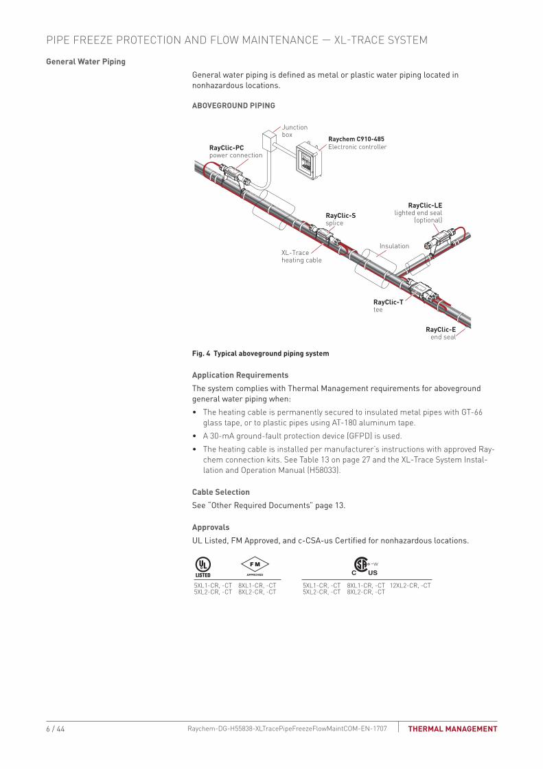
General Water PipingGeneral water piping is defined as metal or plastic water piping located in nonhazardous locations .
AbOVEGROUND PIPING
RayClic-PCpower connection
Junctionbox
XL-Traceheating cable
RayClic-Ssplice
RayClic-Ttee
Insulation
RayClic-LElighted end seal
(optional)
RayClic-Eend seal
Raychem C910-485 Electronic controller
Fig. 4 Typical aboveground piping system
Application Requirements The system complies with Thermal Management requirements for aboveground general water piping when:• The heating cable is permanently secured to insulated metal pipes with GT-66
glass tape, or to plastic pipes using AT-180 aluminum tape.• A 30-mA ground-fault protection device (GFPD) is used.• The heating cable is installed per manufacturer’s instructions with approved Ray-
chem connection kits. See Table 13 on page 27 and the XL-Trace System Instal-lation and Operation Manual (H58033).
Cable SelectionSee “Other Required Documents” page 13 .
ApprovalsUL Listed, FM Approved, and c-CSA-us Certified for nonhazardous locations .
5XL1-CR, -CT5XL2-CR, -CT
8XL1-CR, -CT8XL2-CR, -CT
5XL1-CR, -CT5XL2-CR, -CT
8XL1-CR, -CT8XL2-CR, -CT
12XL2-CR, -CT
-w
PIPE FREEZE PROTECTION AND FLOW MAINTENANCE — XL-TRACE SYSTEM
6 / 44 THERMAL MANAGEMENTRaychem-DG-H55838-XLTracePipeFreezeFlowMaintCOM-EN-1707

bURIED PIPING
RTD10CS
Insulation
Conduit
XL-Traceheating cable
with -CT jacket
Ground
Alternatepower connection
Alternateend seal
Ground
Wall
RayClic-LE*
RayClic-PC*
Junction boxRayClic-E
end seal
Conduit
Wall
with wallmountingbracket
with wallmountingbracket
FTC-XCpower connection
*To protect the heating cable, run cable inside Convolex tubing between the conduit and the RayClic connection kits.
Raychem C910-485Electronic controller
Conduit for temperature sensor
Fig. 5 Typical buried piping system
Application RequirementsThe system complies with Thermal Management requirements for use on buried insulated metal or plastic pipe when:• The heating cable is permanently secured to metal pipes with GT-66 glass tape or
to plastic pipes using AT-180 aluminum tape. • The pipeline is buried at least 2-feet deep.• All heating cable connections (power, splice, tee, and end termination) are made
above-ground. No buried or in-conduit splices or tees are allowed.• The heating cable has a fluoropolymer outer jacket (-CT).• The power connection and end seal are made in UL Listed and CSA Certified
junction boxes above grade.• The heating cable is protected from the pipe to the power connection box in UL
Listed and CSA Certified water-sealed conduit (minimum 3/4-inch diameter) suit-able for the location.
• A 30-mA ground-fault protection device (GFPD) is used. • Closed-cell, waterproof thermal insulation with fire-retardant, waterproof cover-
ing is used.• The heating cable is installed per manufacturer’s instructions with approved
Thermal Management connection kits. See Table 15 on page 29 and the XL-Trace System Installation and Operation Manual (H58033).
Cable SelectionSee “Pipe Heat Loss Calculations,” page 13 .
ApprovalsUL Listed, FM Approved, and c-CSA-us Certified for nonhazardous locations .
5XL1-CT5XL2-CT
8XL1-CT8XL2-CT
5XL1-CT5XL2-CT
8XL1-CT8XL2-CT
12XL2-CT
-w
7 / 44THERMAL MANAGEMENT Raychem-DG-H55838-XLTracePipeFreezeFlowMaintCOM-EN-1707

FLOW MAINTENANCE APPLICATIONS
A flow maintenance system is designed to maintain cooking grease waste lines and #2 fuel oil lines above the temperature at which the viscosity inhibits fluid flow.
Typical Flow Maintenance System
A typical flow maintenance system includes the XL-Trace self-regulating heating cables with a fluoropolymer outer jacket, connection kits, line-sensing temperature control and power distribution.
Splice Kit
Powered Tee Kit
Heating Cable
Lighted End Seal
Power Distribution Panel
Grade
Electronic Controller
RTD
Fig. 6 Typical XL-Trace flow maintenance system
PIPE FREEZE PROTECTION AND FLOW MAINTENANCE — XL-TRACE SYSTEM
8 / 44 THERMAL MANAGEMENTRaychem-DG-H55838-XLTracePipeFreezeFlowMaintCOM-EN-1707

Grease Waste Lines
Grease waste lines are defined as piping used for the disposal of waste oils and fats created in the cooking process. Typical applications include grease waste lines from commercial restaurants. A grease-line flow maintenance system is designed to maintain a 110°F (43°C) minimum fluid temperature.
AbOVEGROUND PIPING
RayClic-PCpowerconnection
Junctionbox
RayClic-Ssplice
Insulation
RayClic-LElighted end seal
RayClic-E
Alternateend seal
XL-Traceheating cablewith -CT jacket
RayClic-SB-04pipe mounting bracket
Raychem C910-485 Electronic controller
RTD10CS
Fig. 7 Typical aboveground piping system
Application RequirementsThe system complies with Thermal Management requirements for aboveground grease waste lines when:• The heating cable is permanently secured to metal pipes with GT-66 glass tape,
or to plastic pipes using AT-180 aluminum tape.• The heating cable must have a fluoropolymer outer jacket (-CT).• A 30-mA ground-fault protection device (GFPD) is used. • Tees and splices are installed using pipe mounting brackets, not in direct contact
with piping.• The heating cable is installed per manufacturer’s instructions with approved
Thermal Management connection kits. See Table 13 on page 27 and the XL-Trace System Installation and Operation Manual (H58033).
Cable SelectionSee “Pipe Heat Loss Calculations,” page 13 .
ApprovalsXL-Trace systems (-CT only) are UL Listed, FM Approved, and c-CSA-us Certified for nonhazardous locations .
5XL1-CT5XL2-CT
8XL1-CT8XL2-CT
5XL1-CT5XL2-CT
8XL1-CT8XL2-CT
12XL2-CT
-w
9 / 44THERMAL MANAGEMENT Raychem-DG-H55838-XLTracePipeFreezeFlowMaintCOM-EN-1707
bURIED PIPING
RTD10CS
Insulation
Conduit
XL-Traceheating cable
with -CT jacket
Ground
Alternatepower connection
Alternateend seal
Ground
Wall
RayClic-LE*
RayClic-PC*
Junction boxRayClic-E
end seal
Conduit
Wall
with wallmountingbracket
with wallmountingbracket
FTC-XCpower connection
*To protect the heating cable, run cable inside Convolex tubing between the conduit and the RayClic connection kits.
Raychem C910-485Electronic controller
Conduit for temperature sensor
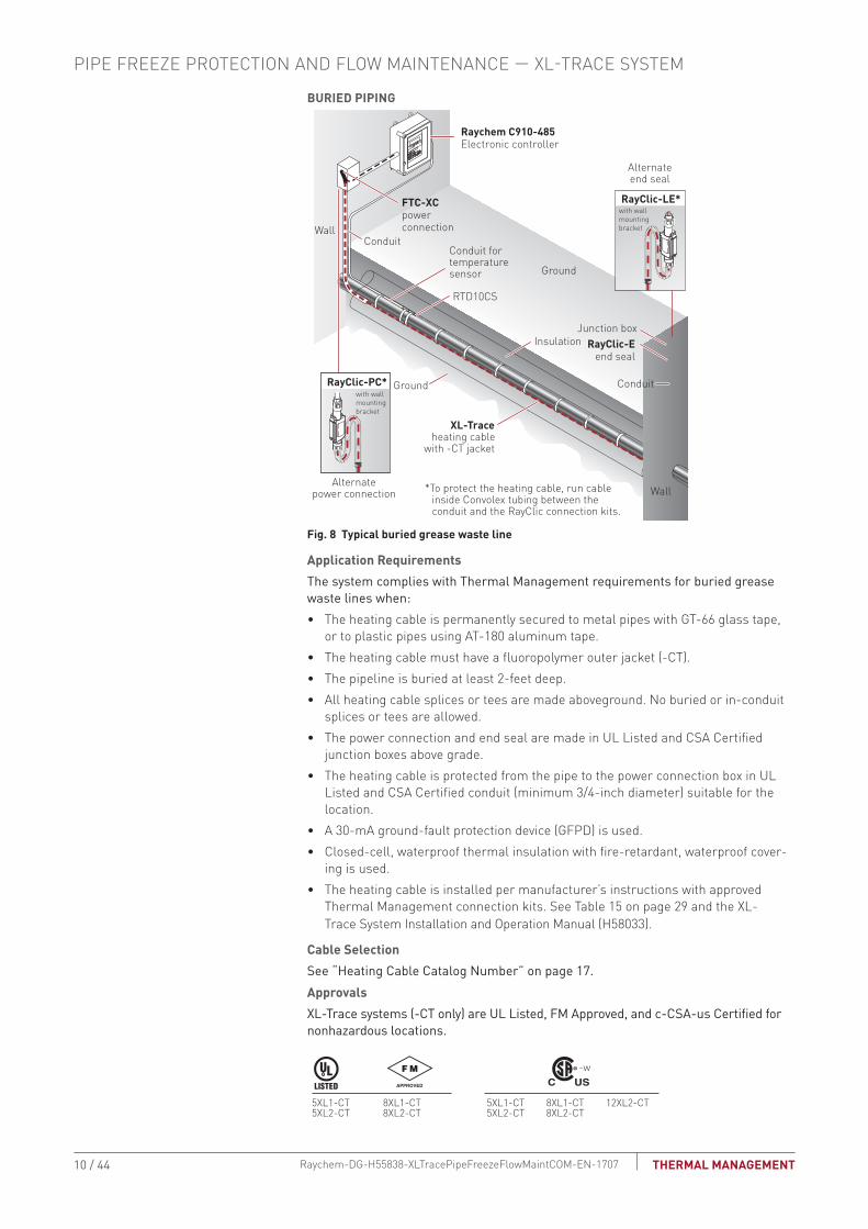
Fig. 8 Typical buried grease waste line
Application RequirementsThe system complies with Thermal Management requirements for buried grease waste lines when:• The heating cable is permanently secured to metal pipes with GT-66 glass tape,
or to plastic pipes using AT-180 aluminum tape.• The heating cable must have a fluoropolymer outer jacket (-CT).• The pipeline is buried at least 2-feet deep.• All heating cable splices or tees are made aboveground. No buried or in-conduit
splices or tees are allowed.• The power connection and end seal are made in UL Listed and CSA Certified
junction boxes above grade.• The heating cable is protected from the pipe to the power connection box in UL
Listed and CSA Certified conduit (minimum 3/4-inch diameter) suitable for the location.
• A 30-mA ground-fault protection device (GFPD) is used. • Closed-cell, waterproof thermal insulation with fire-retardant, waterproof cover-
ing is used.• The heating cable is installed per manufacturer’s instructions with approved
Thermal Management connection kits. See Table 15 on page 29 and the XL-Trace System Installation and Operation Manual (H58033).
Cable SelectionSee “Heating Cable Catalog Number” on page 17 .ApprovalsXL-Trace systems (-CT only) are UL Listed, FM Approved, and c-CSA-us Certified for nonhazardous locations .
5XL1-CT5XL2-CT
8XL1-CT8XL2-CT
5XL1-CT5XL2-CT
8XL1-CT8XL2-CT
12XL2-CT
-w
PIPE FREEZE PROTECTION AND FLOW MAINTENANCE — XL-TRACE SYSTEM
10 / 44 THERMAL MANAGEMENTRaychem-DG-H55838-XLTracePipeFreezeFlowMaintCOM-EN-1707

Fuel LinesFuel lines are defined as those carrying #2 fuel oil . A fuel line flow maintenance system is designed to maintain a 40°F (4°C) minimum fluid temperature to maintain flow .
FOR AbOVEGROUND PIPING ONLY
RayClic-Ssplice
XL-Traceheating cablewith -CT jacket
RTD10CS
RayClic-LElighted end seal
Junctionbox
Insulation
RayClic-PCpowerconnection
RayClic-SB-04pipe mounting bracket
Raychem C910-485 Electronic controller
Fig. 9 Typical aboveground piping system
Application RequirementsThe system complies with Thermal Management requirements for aboveground #2 fuel oil piping when: • The heating cable is permanently secured to metal pipes with GT-66 glass tape or
to plastic pipes using AT-180 aluminum tape.• The heating cable must have a fluoropolymer outer jacket (-CT).• Tees and splices are installed using pipe mounting brackets, not in direct contact
with piping.• A 30-mA ground-fault protection device (GFPD) is used. • The heating cable is installed per manufacturer’s instructions with approved
Thermal Management connection kits. See Table 13 on page 27 and the XL-Trace System Installation and Operation Manual (H58033).
Cable SelectionSee “Pipe Heat Loss Calculations,” page 13 .
ApprovalsXL-Trace systems (-CT only) are UL Listed, FM Approved, and c-CSA-us Certified for nonhazardous locations .
5XL1-CT5XL2-CT
8XL1-CT8XL2-CT
5XL1-CT5XL2-CT
8XL1-CT8XL2-CT
12XL2-CT
-w
11 / 44THERMAL MANAGEMENT Raychem-DG-H55838-XLTracePipeFreezeFlowMaintCOM-EN-1707

PIPE FREEZE PROTECTION AND FLOW MAINTENANCE DESIGN
This section details the design steps necessary to design your application. The examples provided in each step are intended to incrementally illustrate the project parameter output for two sample designs from start to finish. As you go through each step, use the “XL-Trace System Pipe Freeze Protection and Flow Maintenance Design Worksheet,” page 36, to document your project parameters, so that by the end of this section you will have the information you need for your Bill of Materials.
TraceCalc Pro for Buildings is an online design tool available to help you create simple or complex heat-tracing designs for pipe freeze protection or flow maintenance applications. It is available at http://www.pentairthermal.com.
.
Design Step by StepYour system design requires the following essential steps.
Determine design conditions and pipe heat loss
Select the heating cable
Determine the heating cable length
Determine the electrical parameters
Select the connection kits and accessories
Select the control system
Select the power distribution
Complete the Bill of Materials
Pipe Freeze Protectionand Flow Maintenance
1. Determine design conditions and heat loss
2. Select the heating cable
3. Determine the heating cable length
4. Determine the electrical parameters
5. Select the connection kits and accessories
6. Select the control system
7. Select the power distribution
8. Complete the Bill of Materials
Step Determine design conditions and pipe heat loss
Collect the following information to determine your design conditions:• XL-Trace application (from Table 1)• Location
– Indoors – Outdoors – Aboveground – Buried
• Maintain temperature (Tm)• Maximum system temperature (Tmax)• Minimum ambient temperature (Ta)• Pipe diameter and material• Pipe length• Thermal insulation type and thickness• Supply voltage
Example: Pipe Freeze Protection – Water PipingLocation Aboveground, outdoorMaintain temperature (Tm) 40°F (4°C)Maximum system temperature (Tmax) 80°F (27°C)Minimum ambient temperature (Ta) –20°F (–29°C)Pipe diameter and material 2-inch plasticPipe length 300 ft (91 m)Thermal insulation type and thickness 1-inch fiberglassSupply voltage 120 V
PIPE FREEZE PROTECTION AND FLOW MAINTENANCE — XL-TRACE SYSTEM
12 / 44 THERMAL MANAGEMENTRaychem-DG-H55838-XLTracePipeFreezeFlowMaintCOM-EN-1707
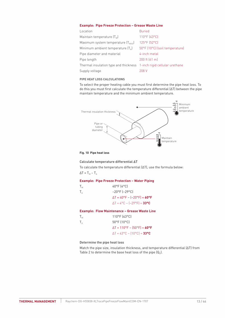
Example: Pipe Freeze Protection – Grease Waste LineLocation BuriedMaintain temperature (Tm) 110°F (43°C)Maximum system temperature (Tmax) 125°F (52°C)Minimum ambient temperature (Ta) 50°F (10°C) (soil temperature)Pipe diameter and material 4-inch metalPipe length 200 ft (61 m)Thermal insulation type and thickness 1-inch rigid cellular urethaneSupply voltage 208 V
PIPE HEAT LOSS CALCULATIONS
To select the proper heating cable you must first determine the pipe heat loss . To do this you must first calculate the temperature differential (ΔT) between the pipe maintain temperature and the minimum ambient temperature .
20406080
−40−20
0+20+40
Maintaintemperature
°F
°F
Minimum ambienttemperatureThermal insulation thickness
Pipe ortubing
diameter
Fig. 10 Pipe heat loss
Calculate temperature differential ΔTTo calculate the temperature differential (ΔT), use the formula below:ΔT = Tm – Ta
Example: Pipe Freeze Protection – Water PipingTm 40°F (4°C)Ta –20°F (–29°C) ΔT = 40°F – (–20°F) = 60°F ΔT = 4°C – (–29°F) = 33°C
Example: Flow Maintenance – Grease Waste LineTm 110°F (43°C)Ta 50°F (10°C) ΔT = 110°F – (50°F) = 60°F ΔT = 43°C – (10°C) = 33°C
Determine the pipe heat lossMatch the pipe size, insulation thickness, and temperature differential (ΔT) from Table 2 to determine the base heat loss of the pipe (Qb) .
13 / 44THERMAL MANAGEMENT Raychem-DG-H55838-XLTracePipeFreezeFlowMaintCOM-EN-1707

Example: Pipe Freeze Protection – Water Piping Pipe diameter 2 inchInsulation thickness 1 inchΔT 60°F (33°C)
Heat loss (Qb) for 60°F must be calculated through interpolation between ΔT at 50°F and ΔT at 100°F from Table 2. For difference between the ΔT of 50°F and the ΔT of 100°F:Qb-50 3.2 W/ft (from Table 2)Qb-100 6.8 W/ft (from Table 2)ΔT interpolation ΔT 60°F is 20% of the distance between ΔT 50°F and ΔT 100°FQb-60 Qb-50 + [0.20 x (Qb-100 – Qb-50)] = 3.2 + [0.20 x (6.8 – 3.2)] = 3.9 W/ftPipe heat loss (Qb) 3.9 W/ft @ Tm 40°F (12.9 W/m @ Tm 4°C)
Example: Flow Maintenance – Grease Waste LinePipe diameter 4 inchInsulation thickness 1 inchΔT 60°F (33°C)
Qb for 60°F must be calculated through interpolation between ΔT at 50°F and ΔT at 100°F from Table 2. For difference between the ΔT of 50°F and the ΔT of 100°F:Qb-50 5.4 W/ft (from Table 2)Qb-100 11.2 W/ft (from Table 2)ΔT interpolation ΔT 60°F is 20% of the distance between ΔT 50°F and ΔT 100°FQb-60 Qb-50 + [0.20 x (Qb-100 – Qb-50)] = 5.4 + [0.20 x (11.2 – 5.4)] = 6.6 W/ftPipe heat loss Qb 6.6 W/ft @ Tm 110°F (21.5 W/m @Tm 43°C)
Compensate for insulation type and pipe locationThe base heat loss is calculated for a pipe insulated with thermal insulation with a k-factor ranging from 0 .2 to 0 .3 BTU/hr–°F-ft2/in (fiberglass or foamed elastomer) in an outdoor, or buried application . To get the heat loss for pipes insulated with alternate types of thermal insulation and for pipes installed indoors, multiply the base heat loss of the pipe (Qb) from Step 3 by the insulation multiple from Table 4 and the indoor multiple from Table 3 to get the corrected heat loss:
Qcorrected = Qb x Insulation multiple x Indoor multiple
Example: Pipe Freeze Protection – Water PipingLocation Aboveground, outdoorThermal insulation thickness and type 1-inch fiberglassPipe heat loss Qb 3 .9 W/ft @ Tm 40°F (12 .9 W/m @ Tm 4°C)Qcorrected 3 .9 W/ft x 1 .00 x 1 .00 = 3.9 W/ft @ Tm 40°F (12.9 W/m @ Tm 4°C)
Example: Flow Maintenance – Grease Waste LineLocation BuriedThermal insulation type and thickness 1-inch rigid cellular urethane Pipe heat loss Qb = 6 .6 W/ft @ Tm 110°F (21 .5 W/m @ Tm 43°C)Qcorrected = 6 .6 W/ft x 0 .6 x 1 .00 = 4.0 W/ft @ Tm 110°F (13.1 W/m @ Tm 43°C)
PIPE FREEZE PROTECTION AND FLOW MAINTENANCE — XL-TRACE SYSTEM
14 / 44 THERMAL MANAGEMENTRaychem-DG-H55838-XLTracePipeFreezeFlowMaintCOM-EN-1707

TAbLE 2 PIPE HEAT LOSS (Qb) FOR OUTDOOR OR bURIED PIPE (W/FT) FOR 1/2 TO 3-1/2 INCHESInsulation thickness (in)
(ΔT) Pipe diameter (IPS) in inches
°F °C 1/2 3/4 1 1-1/4 1-1/2 2 2-1/2 3 3-1/20.5 20 11 1.0 1.2 1.4 1.6 1.8 2.2 2.5 3.0 3.4
50 28 2.5 2.9 3.5 4.1 4.6 5.5 6.5 7.7 8.6100 56 5.2 6.1 7.2 8.6 9.6 11.5 13.5 16.0 18.0150 83 8.1 9.5 11.2 13.4 14.9 17.9 21.1 25.0 28.1
1.0 20 11 0.6 0.7 0.8 1.0 1.1 1.3 1.5 1.7 1.950 28 1.6 1.9 2.2 2.5 2.8 3.2 3.8 4.4 4.9
100 56 3.4 3.9 4.5 5.2 5.8 6.8 7.8 9.1 10.2150 83 5.3 6.1 7.0 8.2 9.0 10.6 12.2 14.2 15.9
1.5 20 11 0.5 0.6 0.7 0.8 0.8 1.0 1.1 1.3 1.450 28 1.3 1.5 1.7 1.9 2.1 2.4 2.8 3.2 3.6
100 56 2.8 3.1 3.5 4.0 4.4 5.1 5.8 6.7 7.4150 83 4.3 4.8 5.5 6.3 6.9 8.0 9.1 10.5 11.6
2.0 20 11 0.5 0.5 0.6 0.6 0.7 0.8 0.9 1.0 1.150 28 1.1 1.3 1.4 1.6 1.8 2.0 2.3 2.6 2.9
100 56 2.4 2.7 3.0 3.4 3.7 4.2 4.8 5.5 6.0150 83 3.7 4.2 4.7 5.3 5.8 6.6 7.5 8.5 9.4
2.5 20 11 0.4 0.5 0.5 0.6 0.6 0.7 0.8 0.9 1.050 28 1.0 1.2 1.3 1.4 1.6 1.8 2.0 2.3 2.5
100 56 2.2 2.4 2.7 3.0 3.3 3.7 4.2 4.7 5.2150 83 3.4 3.7 4.2 4.7 5.1 5.8 6.5 7.4 8.1
3.0 20 11 0.4 0.4 0.5 0.5 0.6 0.6 0.7 0.8 0.950 28 1.0 1.1 1.2 1.3 1.4 1.6 1.8 2.0 2.2
100 56 2.0 2.2 2.4 2.7 2.9 3.3 3.7 4.2 4.6150 83 3.1 3.4 3.8 4.3 4.6 5.2 5.8 6.6 7.1
4.0 20 11 0.3 0.4 0.4 0.5 0.5 0.5 0.6 0.7 0.750 28 0.9 0.9 1.0 1.1 1.2 1.4 1.5 1.7 1.8
100 56 1.8 2.0 2.1 2.4 2.5 2.9 3.2 3.5 3.8150 83 2.8 3.0 3.4 3.7 4.0 4.4 4.9 5.5 6.0
Note: Multiply the W/ft heat loss values by 3.28 for W/m.
15 / 44THERMAL MANAGEMENT Raychem-DG-H55838-XLTracePipeFreezeFlowMaintCOM-EN-1707

TAbLE 1.2 CONTINUED PIPE HEAT LOSS (Qb) FOR OUTDOOR OR bURIED PIPE (W/FT) FOR 4 TO 20 INCHESInsulation thickness (in)
(ΔT) Pipe diameter (IPS) in inches
°F °C 4 6 8 10 12 14 16 18 200.5 20 11 3.8 5.3 6.8 8.4 9.9 10.8 12.2 13.7 15.2
50 28 9.6 13.6 17.4 21.4 25.2 27.5 31.3 35.0 38.8100 56 20.0 28.4 36.3 44.6 52.5 57.4 65.2 73.0 80.8150 83 31.2 44.3 56.6 69.6 81.9 89.5 101.7 113.8 126.0
1.0 20 11 2.1 2.9 3.7 4.5 5.3 5.8 6.5 7.3 8.050 28 5.4 7.5 9.4 11.5 13.5 14.7 16.6 18.6 20.5
100 56 11.2 15.6 19.7 24.0 28.1 30.6 34.7 38.7 42.8150 83 17.5 24.3 30.7 37.4 43.8 47.8 54.1 60.4 66.7
1.5 20 11 1.5 2.1 2.6 3.2 3.7 4.0 4.5 5.0 5.550 28 3.9 5.3 6.7 8.1 9.4 10.2 11.5 12.9 14.2
100 56 8.1 11.1 13.9 16.8 19.6 21.3 24.0 26.8 29.5150 83 12.7 17.3 21.6 26.2 30.5 33.2 37.5 41.8 46.1
2.0 20 11 1.2 1.7 2.1 2.5 2.9 3.1 3.5 3.9 4.350 28 3.1 4.2 5.2 6.3 7.3 7.9 8.9 9.9 10.9
100 56 6.6 8.8 10.9 13.1 15.2 16.5 18.6 20.7 22.8150 83 10.2 13.8 17.0 20.5 23.8 25.8 29.0 32.3 35.5
2.5 20 11 1.1 1.4 1.7 2.1 2.4 2.6 2.9 3.2 3.550 28 2.7 3.6 4.4 5.2 6.1 6.6 7.4 8.2 9.0
100 56 5.6 7.4 9.1 10.9 12.6 13.7 15.3 17.0 18.7150 83 8.7 11.6 14.2 17.0 19.7 21.3 23.9 26.5 29.1
3.0 20 11 0.9 1.2 1.5 1.8 2.0 2.2 2.5 2.7 3.050 28 2.4 3.1 3.8 4.5 5.2 5.6 6.3 7.0 7.6
100 56 4.9 6.5 7.9 9.4 10.8 11.7 13.1 14.5 15.9150 83 7.7 10.1 12.4 14.7 16.9 18.3 20.5 22.6 24.8
4.0 20 11 0.8 1.0 1.2 1.4 1.6 1.7 1.9 2.1 2.350 28 2.0 2.5 3.1 3.6 4.1 4.4 5.0 5.5 6.0
100 56 4.1 5.3 6.4 7.5 8.6 9.3 10.3 11.4 12.4150 83 6.4 8.3 10.0 11.8 13.4 14.5 16.1 17.8 19.4
Note: Multiply the W/ft heat loss values by 3.28 for W/m.
TAbLE 3 INDOOR PIPE HEAT LOSS MULTIPLESFiberglass thickness (in) Indoor multiple0.5 0.791 0.881.5 0.912 0.932.5 0.943 0.954 0.97
PIPE FREEZE PROTECTION AND FLOW MAINTENANCE — XL-TRACE SYSTEM
16 / 44 THERMAL MANAGEMENTRaychem-DG-H55838-XLTracePipeFreezeFlowMaintCOM-EN-1707

TAbLE 4 INSULATION HEAT LOSS MULTIPLESk factor at 50°F (10°C) (bTU/hr–°F-ft2/in) Insulation multiple Examples of preformed pipe insulation0.1–0.2 0.6 Rigid cellular urethane (ASTM C591)0.2–0.3 1.0 Glass fiber (ASTM C547)
Foamed elastomer (ASTM C534)0.3–0.4 1.4 Cellular glass (ASTM C552)
Mineral fiber blanket (ASTM C553)
Pipe Freeze Protectionand Flow Maintenance
2. Select the heating cable
3. Determine the heating cable length
4. Determine the electrical parameters
5. Select the connection kits and accessories
6. Select the control system
7. Select the power distribution
8. Complete the Bill of Materials
1. Determine design conditions and heat loss
Step Select the heating cable
To select the appropriate XL-Trace heating cable for your application, you must determine your cable supply voltage, power output, and outer jacket. Once you select these, you will be able to determine the catalog number for your cable.
HEATING CAbLE CATALOG NUMbERBefore beginning, take a moment to understand the structure underlying heating cable catalog numbers . You will refer to this numbering convention throughout the product selection process . Your goal is to determine the catalog number for the product that best suits your needs .
Fig. 11 Heating cable catalog number
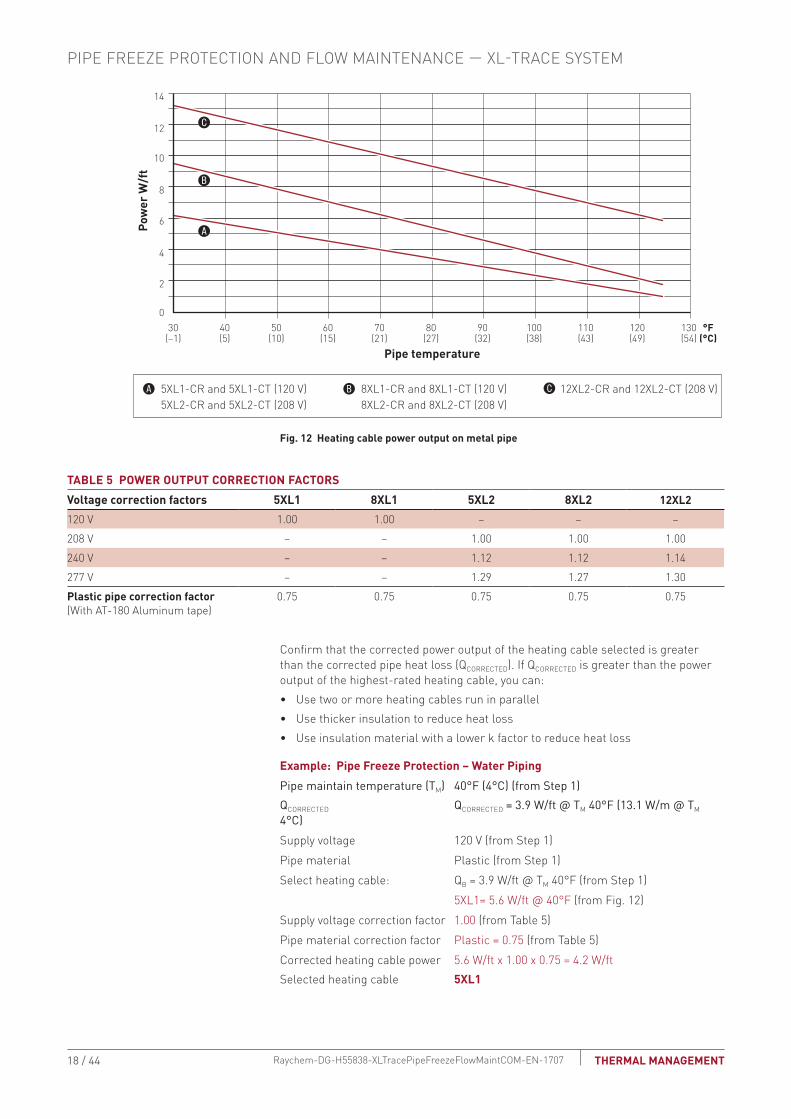
Select the heating cable from Fig. 12 that provides the required power output to match the corrected heat loss for your application. Fig. 12 shows the power output for the heating cables on metal pipe at 120/208 volts. To correct the power output for other applied voltage or plastic pipes multiply the power output at the desired maintain temperature by the factors listed in Table 5. If the pipe heat loss, Qcorrected, is between the two heating cable power output curves, select the higher-rated heating cable.
Catalog number: 5, 8 or 12 XL 1 or 2 -CR -CT
Power output (W/ft)
Product family
Voltage 1 = 120 V (only available for 5 or 8) 2 = 208, 240, 277 V (available for 5, 8, or 12)
Jacket type: Polyolefin
Fluoropolymer (required for buried pipes, grease and fuel lines)or
17 / 44THERMAL MANAGEMENT Raychem-DG-H55838-XLTracePipeFreezeFlowMaintCOM-EN-1707
5XL1-CR and 5XL1-CT (120 V)5XL2-CR and 5XL2-CT (208 V)
8XL1-CR and 8XL1-CT (120 V)8XL2-CR and 8XL2-CT (208 V)
12XL2-CR and 12XL2-CT (208 V)
Pipe temperature
Pow
er W
/ft
50(10)
30(–1)
40(5)
60(15)
70(21)
80(27)
90(32)
100(38)
110(43)
120(49)
130(54)
°F(°C)
10
8
14
12
6
4
2
0
Fig. 12 Heating cable power output on metal pipe
TAbLE 5 POWER OUTPUT CORRECTION FACTORSVoltage correction factors 5XL1 8XL1 5XL2 8XL2 12XL2120 V 1.00 1.00 – – –208 V – – 1.00 1.00 1.00240 V – – 1.12 1.12 1.14277 V – – 1.29 1.27 1.30Plastic pipe correction factor (With AT-180 Aluminum tape)
0.75 0.75 0.75 0.75 0.75
Confirm that the corrected power output of the heating cable selected is greater than the corrected pipe heat loss (Qcorrected). If Qcorrected is greater than the power output of the highest-rated heating cable, you can:• Use two or more heating cables run in parallel• Use thicker insulation to reduce heat loss• Use insulation material with a lower k factor to reduce heat loss
Example: Pipe Freeze Protection – Water PipingPipe maintain temperature (Tm) 40°F (4°C) (from Step 1)Qcorrected Qcorrected = 3 .9 W/ft @ Tm 40°F (13 .1 W/m @ Tm 4°C)Supply voltage 120 V (from Step 1)Pipe material Plastic (from Step 1)Select heating cable: Qb = 3.9 W/ft @ Tm 40°F (from Step 1) 5XL1= 5.6 W/ft @ 40°F (from Fig. 12)Supply voltage correction factor 1.00 (from Table 5)Pipe material correction factor Plastic = 0.75 (from Table 5)Corrected heating cable power 5.6 W/ft x 1.00 x 0.75 = 4.2 W/ftSelected heating cable 5XL1
PIPE FREEZE PROTECTION AND FLOW MAINTENANCE — XL-TRACE SYSTEM
18 / 44 THERMAL MANAGEMENTRaychem-DG-H55838-XLTracePipeFreezeFlowMaintCOM-EN-1707
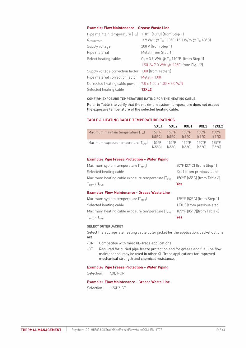
Example: Flow Maintenance – Grease Waste LinePipe maintain temperature (Tm) 110°F (43°C) (from Step 1)Qcorrected 3.9 W/ft @ Tm 110°F (13.1 W/m @ Tm 43°C)Supply voltage 208 V (from Step 1)Pipe material Metal (from Step 1)Select heating cable: Qb = 3.9 W/ft @ Tm 110°F (from Step 1) 12XL2= 7.0 W/ft @110°F (from Fig. 12)Supply voltage correction factor 1.00 (from Table 5)Pipe material correction factor Metal = 1.00Corrected heating cable power 7.0 x 1.00 x 1.00 = 7.0 W/ftSelected heating cable 12XL2
CONFIRM EXPOSURE TEMPERATURE RATING FOR THE HEATING CAbLE
Refer to Table 6 to verify that the maximum system temperature does not exceed the exposure temperature of the selected heating cable .
TAbLE 6 HEATING CAbLE TEMPERATURE RATINGS5XL1 5XL2 8XL1 8XL2 12XL2
Maximum maintain temperature (Tm) 150°F(65°C)
150°F(65°C)
150°F(65°C)
150°F(65°C)
150°F(65°C)
Maximum exposure temperature (Texp) 150°F(65°C)
150°F(65°C)
150°F(65°C)
150°F(65°C)
185°F(85°C)
Example: Pipe Freeze Protection – Water PipingMaximum system temperature (Tmax) 80°F (27°C) (from Step 1)Selected heating cable 5XL1 (from previous step)Maximum heating cable exposure temperature (Texp) 150°F (65°C) (from Table 6)Tmax < Texp Yes
Example: Flow Maintenance - Grease Waste LineMaximum system temperature (Tmax) 125°F (52°C) (from Step 1)Selected heating cable 12XL2 (from previous step)Maximum heating cable exposure temperature (Texp) 185°F (85°C)(from Table 6)Tmax < Texp Yes
SELECT OUTER JACKET
Select the appropriate heating cable outer jacket for the application . Jacket options are:-CR Compatible with most XL-Trace applications-CT Required for buried pipe freeze protection and for grease and fuel line flow maintenance; may be used in other XL-Trace applications for improved mechanical strength and chemical resistance .
Example: Pipe Freeze Protection – Water PipingSelection: 5XL1-CR
Example: Flow Maintenance - Grease Waste LineSelection: 12XL2-CT
19 / 44THERMAL MANAGEMENT Raychem-DG-H55838-XLTracePipeFreezeFlowMaintCOM-EN-1707

Pipe Freeze Protectionand Flow Maintenance
2. Select the heating cable
3. Determine the heating cable length
4. Determine the electrical parameters
5. Select the connection kits and accessories
6. Select the control system
7. Select the power distribution
8. Complete the Bill of Materials
1. Determine design conditions and heat loss
Step Determine the heating cable length
In Step 2 you selected the appropriate heating cable and the number of runs of heating cable required for the pipe. Multiply the length of the pipe by the number of heating cable runs for the heating cable length.
Additional heating cable will be required for heat sinks and connection kits. Use Table 7 and Table 8 to determine the additional footage required for heat sinks (valves, flanges, and pipe supports). You will determine the additional heating cable for connection kits in Step 5. Round up fractional lengths to ensure heating cable lengths are sufficient.
TAbLE 7 ADDITIONAL HEATING CAbLE FOR VALVESPipe diameter (IPS) (inches) Heating cable (feet (meters))1/2 0.8 (0.24)3/4 1.3 (0.4)1 2.0 (0.6)1-1/4 3.3 (1.1)1-1/2 4.3 (1.3)2 4.3 (1.3)3 4.3 (1.3)4 4.3 (1.3)6 5.0 (1.5)8 5.0 (1.5)10 5.6 (1.7)12 5.9 (1.9)14 7.3 (2.2)18 9.4 (2.9)20 10.5 (3.2)
TAbLE 8 ADDITIONAL HEATING CAbLE FOR PIPE SUPPORTS AND FLANGESSupport Additional cablePipe hangers (insulated) No additional heating cablePipe hangers noninsulated and U-bolt supports
Add 2x pipe diameter
Welded support shoes Add 3x the length of the shoe
Flanges Add 2x pipe diameterNote: For applications where more than one heating cable is required per foot of pipe, this correction factor applies for each cable run.
Heating cable length = Pipe length x No. heating cable runs
Total heating cable length required
(Pipe length x No. heating cable runs)
Additional heating cable for heat sinks (valves, pipe supports, and flanges)
= +
PIPE FREEZE PROTECTION AND FLOW MAINTENANCE — XL-TRACE SYSTEM
20 / 44 THERMAL MANAGEMENTRaychem-DG-H55838-XLTracePipeFreezeFlowMaintCOM-EN-1707
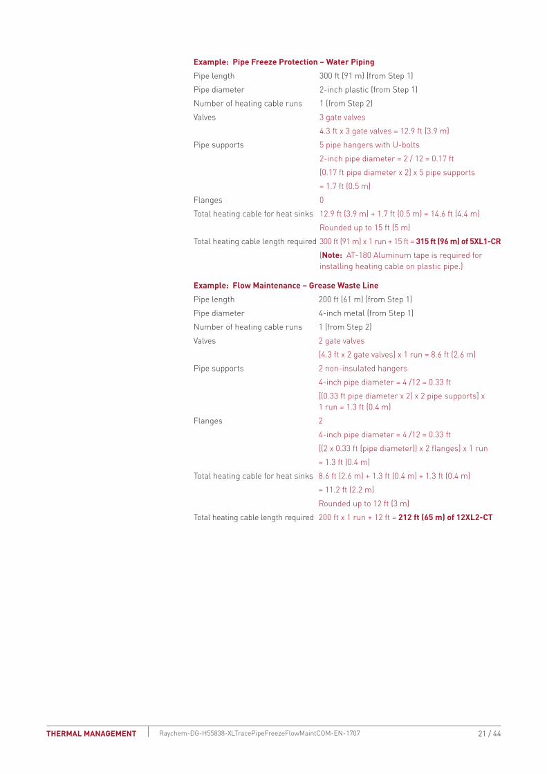
Example: Pipe Freeze Protection – Water PipingPipe length 300 ft (91 m) (from Step 1)Pipe diameter 2-inch plastic (from Step 1)Number of heating cable runs 1 (from Step 2)Valves 3 gate valves 4.3 ft x 3 gate valves = 12.9 ft (3.9 m)Pipe supports 5 pipe hangers with U-bolts 2-inch pipe diameter = 2 / 12 = 0.17 ft [0.17 ft pipe diameter x 2] x 5 pipe supports = 1.7 ft (0.5 m)Flanges 0Total heating cable for heat sinks 12.9 ft (3.9 m) + 1.7 ft (0.5 m) = 14.6 ft (4.4 m) Rounded up to 15 ft (5 m)Total heating cable length required 300 ft (91 m) x 1 run + 15 ft = 315 ft (96 m) of 5XL1-CR (Note: AT-180 Aluminum tape is required for installing heating cable on plastic pipe.)
Example: Flow Maintenance – Grease Waste LinePipe length 200 ft (61 m) (from Step 1)Pipe diameter 4-inch metal (from Step 1)Number of heating cable runs 1 (from Step 2)Valves 2 gate valves [4.3 ft x 2 gate valves] x 1 run = 8.6 ft (2.6 m)Pipe supports 2 non-insulated hangers 4-inch pipe diameter = 4 /12 = 0.33 ft [(0.33 ft pipe diameter x 2) x 2 pipe supports] x 1 run = 1.3 ft (0.4 m)Flanges 2 4-inch pipe diameter = 4 /12 = 0.33 ft [(2 x 0.33 ft (pipe diameter)) x 2 flanges] x 1 run = 1.3 ft (0.4 m)Total heating cable for heat sinks 8.6 ft (2.6 m) + 1.3 ft (0.4 m) + 1.3 ft (0.4 m) = 11.2 ft (2.2 m) Rounded up to 12 ft (3 m)Total heating cable length required 200 ft x 1 run + 12 ft = 212 ft (65 m) of 12XL2-CT
21 / 44THERMAL MANAGEMENT Raychem-DG-H55838-XLTracePipeFreezeFlowMaintCOM-EN-1707

Pipe Freeze Protectionand Flow Maintenance
2. Select the heating cable
3. Determine the heating cable length
4. Determine the electrical parameters
5. Select the connection kits and accessories
6. Select the control system
7. Select the power distribution
8. Complete the Bill of Materials
1. Determine design conditions and heat loss
Step Determine the electrical parameters
To determine the electrical requirements for your application, you must determine the number of circuits and calculate the transformer load.
DETERMINE NUMbER OF CIRCUITS
To determine the number of circuits, you need to know:• Total heating cable length• Supply voltage• Minimum start-up temperature
Use Table 9 to determine the maximum circuit length allowed. If the total heating cable length exceeds the maximum circuit length for the expected start-up temperature, more than one circuit will be required.
Number of circuits = Heating cable length required Maximum heating cable circuit length
Important: Select the smallest appropriate ground-fault circuit breaker size.
WARNING: To minimize the danger of fire from sustained electrical arcing if the heating cable is damaged or improperly installed, and to comply with the requirements of Thermal Management, agency certifications, and national electrical codes, ground-fault equipment protection must be used on each heating cable branch circuit. Arcing may not be stopped by conventional circuit protection.
PIPE FREEZE PROTECTION AND FLOW MAINTENANCE — XL-TRACE SYSTEM
22 / 44 THERMAL MANAGEMENTRaychem-DG-H55838-XLTracePipeFreezeFlowMaintCOM-EN-1707

TAbLE 9 MAXIMUM CIRCUIT LENGTH IN FEET40°F / 110°F Maintain*
Start-up temperature (°F)
Cb size (A)
5XL1 8XL1 5XL2 8XL2 12XL2
120 V 120 V 208 V 240 V 277 V 208 V 240 V 277 V 208 V 240 V 277 V–20°F 15 101 76 174 178 183 131 138 146 111 114 117
20 134 101 232 237 245 175 184 194 148 151 15630 201 151 349 356 367 262 276 291 223 227 23440 270 201 465 474 478 349 368 388 297 303 312
0°F 15 115 86 199 203 209 149 157 166 120 122 12620 153 115 265 271 279 199 209 221 160 163 16830 230 172 398 406 419 298 314 331 239 244 25240 270 210 470 490 530 370/399 390/420 420/443 319 326 336
20°F 15 134 100 232 237 244 173 182 192 126 129 13320 178 133 309 315 325 231 243 257 169 172 17730 270 200 464 473 488 346 365 385 253 258 26640 270 210 470 490 530 370/462 390/486 420/513 340/349 344 355
40°F 15 160 119 278 283 292 206 217 229 142 145 15020 214 159 370 378 390 275 290 306 190 194 20030 270 210 470 490 530 370/416 390/438 420/462 285 291 30040 270 210 470 490 530 370/554 390/584 420/616 340/398 360/406 380/419
50°F(buried)
15 – – – – – 228 240 254 152 155 16020 – – – – – 304 320 338 203 207 21330 – – – – – 457 481 507 304 310 32040 – – – – – 609 641 676 405 414 427
65°F(indoors grease)
15 – – – – – 272 286 302 169 172 17820 – – – – – 362 381 402 225 230 23730 – – – – – 543 572 603 338 345 35640 – – – – – 610 660 720 430 460 490
* When maximum circuit length is listed in:•blacktype,thevalueisforapplicationswitha40°Fmaintain•red type, the value is for applications with a 110°F maintain
23 / 44THERMAL MANAGEMENT Raychem-DG-H55838-XLTracePipeFreezeFlowMaintCOM-EN-1707
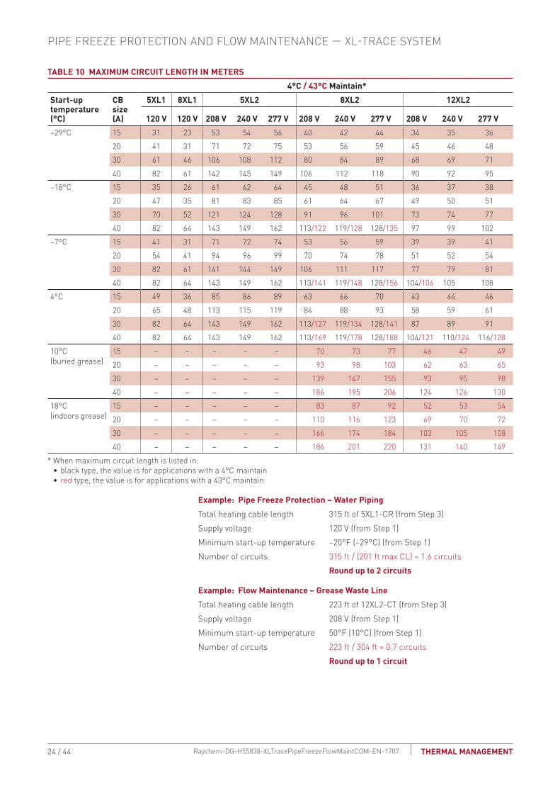
TAbLE 10 MAXIMUM CIRCUIT LENGTH IN METERS4°C / 43°C Maintain*
Start-up temperature (°C)
Cb size (A)
5XL1 8XL1 5XL2 8XL2 12XL2
120 V 120 V 208 V 240 V 277 V 208 V 240 V 277 V 208 V 240 V 277 V–29°C 15 31 23 53 54 56 40 42 44 34 35 36
20 41 31 71 72 75 53 56 59 45 46 4830 61 46 106 108 112 80 84 89 68 69 7140 82 61 142 145 149 106 112 118 90 92 95
–18°C 15 35 26 61 62 64 45 48 51 36 37 3820 47 35 81 83 85 61 64 67 49 50 5130 70 52 121 124 128 91 96 101 73 74 7740 82 64 143 149 162 113/122 119/128 128/135 97 99 102
–7°C 15 41 31 71 72 74 53 56 59 39 39 4120 54 41 94 96 99 70 74 78 51 52 5430 82 61 141 144 149 106 111 117 77 79 8140 82 64 143 149 162 113/141 119/148 128/156 104/106 105 108
4°C 15 49 36 85 86 89 63 66 70 43 44 4620 65 48 113 115 119 84 88 93 58 59 6130 82 64 143 149 162 113/127 119/134 128/141 87 89 9140 82 64 143 149 162 113/169 119/178 128/188 104/121 110/124 116/128
10°C(buried grease)
15 – – – – – 70 73 77 46 47 4920 – – – – – 93 98 103 62 63 6530 – – – – – 139 147 155 93 95 9840 – – – – – 186 195 206 124 126 130
18°C(indoors grease)
15 – – – – – 83 87 92 52 53 5420 – – – – – 110 116 123 69 70 7230 – – – – – 166 174 184 103 105 10840 – – – – – 186 201 220 131 140 149
* When maximum circuit length is listed in:•blacktype,thevalueisforapplicationswitha4°Cmaintain•red type, the value is for applications with a 43°C maintain
Example: Pipe Freeze Protection – Water PipingTotal heating cable length 315 ft of 5XL1-CR (from Step 3)Supply voltage 120 V (from Step 1)Minimum start-up temperature –20°F (–29°C) (from Step 1)Number of circuits 315 ft / (201 ft max CL) = 1.6 circuits Round up to 2 circuits
Example: Flow Maintenance – Grease Waste LineTotal heating cable length 223 ft of 12XL2-CT (from Step 3)Supply voltage 208 V (from Step 1)Minimum start-up temperature 50°F (10°C) (from Step 1)Number of circuits 223 ft / 304 ft = 0.7 circuits Round up to 1 circuit
PIPE FREEZE PROTECTION AND FLOW MAINTENANCE — XL-TRACE SYSTEM
24 / 44 THERMAL MANAGEMENTRaychem-DG-H55838-XLTracePipeFreezeFlowMaintCOM-EN-1707

DETERMINE TRANSFORMER LOAD
Transformers must be sized to handle the load of the heating cable . Use the following tables to calculate the total transformer load .
TAbLE 11 TRANSFORMER SIZING (AMPERES/FOOT)
Minimum start-up temperature (°F)
5XL1 8XL1 5XL2 8XL2 12XL2120 120 208 240 277 208 240 277 208 240 277
–20 0.119 0.159 0.069 0.067 0.065 0.092 0.087 0.082 0.108 0.106 0.1020 0.105 0.139 0.060 0.059 0.057 0.080 0.076 0.072 0.100 0.098 0.095
20 0.090 0.120 0.052 0.051 0.049 0.069 0.066 0.062 0.095 0.093 0.09040 0.075 0.101 0.043 0.042 0.041 0.058 0.055 0.052 0.084 0.083 0.08050 – – – – – 0.053 0.050 0.047 0.079 0.077 0.075
65 – – – – – 0.044 0.042 0.040 0.072 0.070 0.067
TAbLE 12 TRANSFORMER SIZING (AMPERES/METER)
Minimum start-up temperature (°C)
5XL1 8XL1 5XL2 8XL2 12XL2120 120 208 240 277 208 240 277 208 240 277
–20 0.391 0.521 0.226 0.221 0.215 0.301 0.286 0.270 0.354 0.347 0.336–18 0.343 0.457 0.198 0.194 0.188 0.264 0.251 0.238 0.329 0.322 0.312
–7 0.294 0.394 0.170 0.166 0.161 0.227 0.216 0.205 0.311 0.305 0.2964 0.246 0.331 0.142 0.139 0.135 0.191 0.181 0.172 0.276 0.271 0.263
10 – – – – – 0.172 0.164 0.155 0.259 0.254 0.24618 – – – – – 0.145 0.138 0.130 0.233 0.228 0.221
Use Table 11 or Table 12 to determine the applied voltage and the maximum A/ft (A/m) at the minimum start up temperature to calculate the transformer load as follows:
Example: Pipe Freeze Protection – Water PipingTotal heating cable length 315 ft of 5XL1-CR (from Step 3)Minimum start-up temperature –20°F (–29°C) (from Step 1)Circuit breaker sizing 30 A
1000= Transformer load (kW)
Max A/ft at minimum start-up temperature x Heating cable length (ft) x Supply voltage
= (0.119 A/ft x 315 ft x 120 V) / 1000
= 4.5 kWTransformer load (kW)
1000
Max A/ft at –20°F x Total feet x Supply voltage
25 / 44THERMAL MANAGEMENT Raychem-DG-H55838-XLTracePipeFreezeFlowMaintCOM-EN-1707
Example: Flow Maintenance – Grease Waste LineTotal heating cable length 212 ft of 12XL2-CT (from Step 3)Supply voltage 208 V Minimum start-up temperature 50°F (10°C) (from Step 1)
Pipe Freeze Protectionand Flow Maintenance
2. Select the heating cable
3. Determine the heating cable length
4. Determine the electrical parameters
5. Select the connection kits and accessories
6. Select the control system
7. Select the power distribution
8. Complete the Bill of Materials
1. Determine design conditions and heat loss
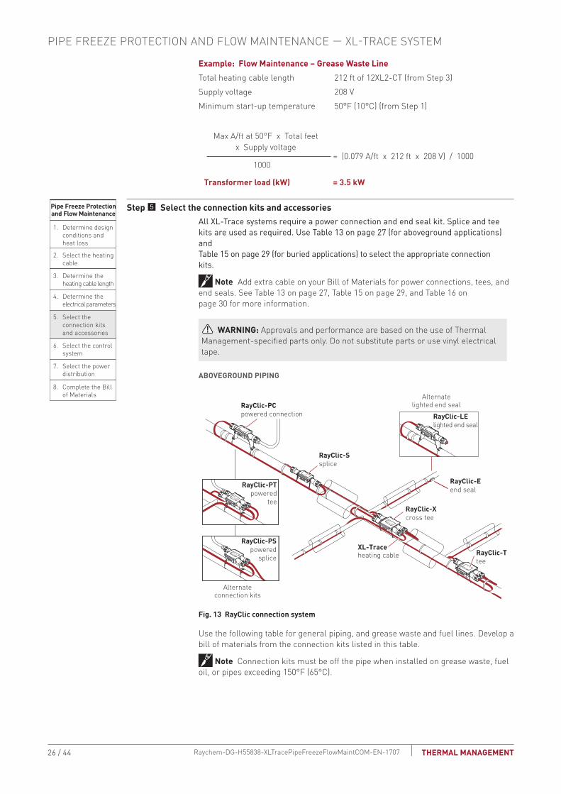
Step Select the connection kits and accessoriesAll XL-Trace systems require a power connection and end seal kit . Splice and tee kits are used as required . Use Table 13 on page 27 (for aboveground applications) and Table 15 on page 29 (for buried applications) to select the appropriate connection kits .
Note: Add extra cable on your Bill of Materials for power connections, tees, and end seals. See Table 13 on page 27, Table 15 on page 29, and Table 16 on page 30 for more information.
WARNING: Approvals and performance are based on the use of Thermal Management-specified parts only. Do not substitute parts or use vinyl electrical tape.
AbOVEGROUND PIPING
Fig. 13 RayClic connection system
Use the following table for general piping, and grease waste and fuel lines. Develop a bill of materials from the connection kits listed in this table.
Note: Connection kits must be off the pipe when installed on grease waste, fuel oil, or pipes exceeding 150°F (65°C).
= (0.079 A/ft x 212 ft x 208 V) / 1000
= 3.5 kWTransformer load (kW)
1000
Max A/ft at 50°F x Total feet x Supply voltage
RayClic-PTpowered
tee
RayClic-PCpowered connection
RayClic-Ssplice
RayClic-Xcross tee
RayClic-Ttee
RayClic-PSpowered
splice
RayClic-LElighted end seal
RayClic-Eend seal
Alternatelighted end seal
Alternateconnection kits
XL-Traceheating cable
PIPE FREEZE PROTECTION AND FLOW MAINTENANCE — XL-TRACE SYSTEM
26 / 44 THERMAL MANAGEMENTRaychem-DG-H55838-XLTracePipeFreezeFlowMaintCOM-EN-1707
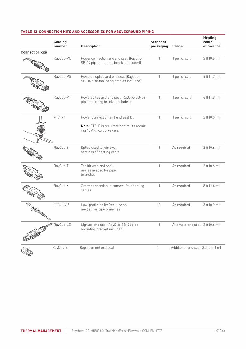
TAbLE 13 CONNECTION KITS AND ACCESSORIES FOR AbOVEGROUND PIPING
Catalog number Description
Standard packaging Usage
Heating cable allowance1
Connection kitsRayClic-PC Power connection and end seal (RayClic-
SB-04 pipe mounting bracket included)1 1 per circuit 2 ft (0.6 m)
RayClic-PS Powered splice and end seal (RayClic-SB-04 pipe mounting bracket included)
1 1 per circuit 4 ft (1.2 m)
RayClic-PT Powered tee and end seal (RayClic-SB-04 pipe mounting bracket included)
1 1 per circuit 6 ft (1.8 m)
FTC-P2 Power connection and end seal kit
Note: FTC-P is required for circuits requir-ing 40 A circuit breakers.
1 1 per circuit 2 ft (0.6 m)
RayClic-S Splice used to join twosections of heating cable
1 As required 2 ft (0.6 m)
RayClic-T Tee kit with end seal;use as needed for pipebranches
1 As required 2 ft (0.6 m)
RayClic-X Cross connection to connect four heating cables
1 As required 8 ft (2.4 m)
FTC-HST3 Low-profile splice/tee; use asneeded for pipe branches
2 As required 3 ft (0.9 m)
RayClic-LE Lighted end seal (RayClic-SB-04 pipe mounting bracket included)
1 Alternate end seal 2 ft (0.6 m)
RayClic-E Replacement end seal 1 Additional end seal 0.3 ft (0.1 m)
27 / 44THERMAL MANAGEMENT Raychem-DG-H55838-XLTracePipeFreezeFlowMaintCOM-EN-1707
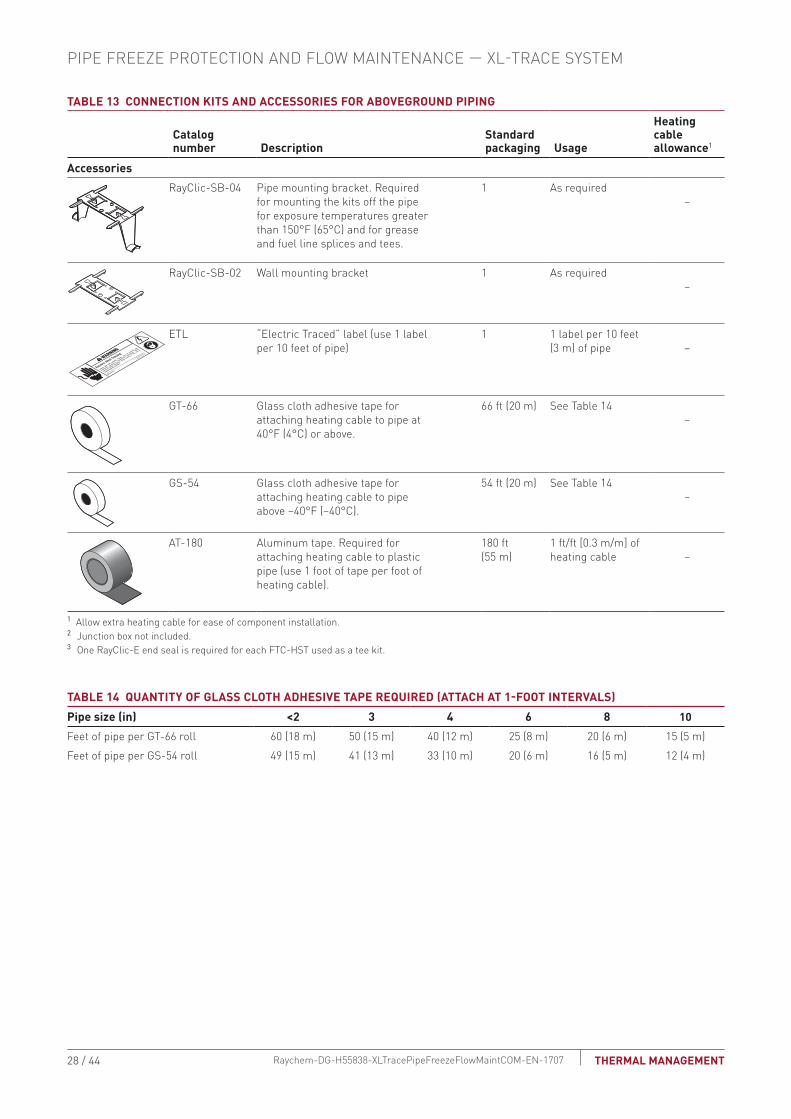
TAbLE 13 CONNECTION KITS AND ACCESSORIES FOR AbOVEGROUND PIPING
Catalog number Description
Standard packaging Usage
Heating cable allowance1
AccessoriesRayClic-SB-04 Pipe mounting bracket. Required
for mounting the kits off the pipefor exposure temperatures greaterthan 150°F (65°C) and for greaseand fuel line splices and tees.
1 As required –
RayClic-SB-02 Wall mounting bracket 1 As required –
© 2013 Pentair Thermal M
anagement LLC
WWW.PENTAIRTHERMAL.COM
PN C77203-000 H57657
07/13
Electric Heat Tr
acingWA
RNING
SHOCK AND FIRE HAZARD: System must be installed and
maintained according to manufacturer's instructions. Follow
electrical lockout procedures before working on this line or
removing thermal insulation.
ETL “Electric Traced” label (use 1 labelper 10 feet of pipe)
1 1 label per 10 feet (3 m) of pipe
–
GT-66 Glass cloth adhesive tape forattaching heating cable to pipe at40°F (4°C) or above.
66 ft (20 m) See Table 14 –
GS-54 Glass cloth adhesive tape forattaching heating cable to pipeabove –40°F (–40°C).
54 ft (20 m) See Table 14 –
AT-180 Aluminum tape. Required forattaching heating cable to plasticpipe (use 1 foot of tape per foot ofheating cable).
180 ft (55 m)
1 ft/ft [0.3 m/m] of heating cable
–
1 Allow extra heating cable for ease of component installation.2 Junction box not included. 3 One RayClic-E end seal is required for each FTC-HST used as a tee kit.
TAbLE 14 QUANTITY OF GLASS CLOTH ADHESIVE TAPE REQUIRED (ATTACH AT 1-FOOT INTERVALS)Pipe size (in) <2 3 4 6 8 10Feet of pipe per GT-66 roll 60 (18 m) 50 (15 m) 40 (12 m) 25 (8 m) 20 (6 m) 15 (5 m)Feet of pipe per GS-54 roll 49 (15 m) 41 (13 m) 33 (10 m) 20 (6 m) 16 (5 m) 12 (4 m)
PIPE FREEZE PROTECTION AND FLOW MAINTENANCE — XL-TRACE SYSTEM
28 / 44 THERMAL MANAGEMENTRaychem-DG-H55838-XLTracePipeFreezeFlowMaintCOM-EN-1707

bURIED PIPING
RTD10CS
Insulation
Conduit
XL-Traceheating cable
with -CT jacket
Ground
Alternatepower connection
Alternateend seal
Ground
Wall
RayClic-LE*
RayClic-PC*
Junction boxRayClic-E
end seal
Conduit
Wall
with wallmountingbracket
with wallmountingbracket
FTC-XCpower connection
*To protect the heating cable, run cable inside Convolex tubing between the conduit and the RayClic connection kits.
Raychem C910-485Electronic controller
Conduit for temperature sensor
Fig. 14 Typical buried piping system
Use the following for buried water piping and grease waste lines. Note that all connections must be aboveground and that no splices/tees are allowed. Develop a bill of materials from the connection kits in this table.
TAbLE 15 CONNECTION KITS AND ACCESSORIES FOR bURIED PIPINGCatalog number Description
Standard packaging Usage
Heating cable allowance1
RayClic-PC Power connection and end seal (RayClic-SB-04 pipe mounting bracket included)
1 1 per circuit 2 ft (0.6 m)
FTC-XC The FTC-XC power connection and end seal kit is for use with XL-Trace heating cable that is run through conduit to a junction box. Materials for one power connection and end seal is included in the kit.
Note: FTC-XC is required for circuits requiring 40 A circuit breakers.
1 1 per circuit 2 ft (0.6 m)
RayClic-LE Lighted end seal (RayClic-SB-04 pipe mounting bracket included)
1 Alternate end seal
2 ft (0.6 m)
RayClic-E Replacement end seal 1 Additional end seal
0.3 ft (0.1 m)
29 / 44THERMAL MANAGEMENT Raychem-DG-H55838-XLTracePipeFreezeFlowMaintCOM-EN-1707

TAbLE 15 CONNECTION KITS AND ACCESSORIES FOR bURIED PIPINGCatalog number Description
Standard packaging Usage
Heating cable allowance1
AccessoriesRayClic-SB-04 Pipe mounting bracket 1 As required –
RayClic-SB-02 Wall mounting bracket 1 As required –
© 2013 Pentair Thermal M
anagement LLC
WWW.PENTAIRTHERMAL.COM
PN C77203-000 H57657
07/13
Electric Heat Tr
acingWA
RNING
SHOCK AND FIRE HAZARD: System must be installed and
maintained according to manufacturer's instructions. Follow
electrical lockout procedures before working on this line or
removing thermal insulation.
ETL “Electric Traced” label (use 1label per 10 feet of pipe)
1 1 label per 10 feet (3 m) of pipe
–
GT-66 Glass cloth adhesive tape forattaching heating cable to pipe at40°F (4°C) or above.
66 ft (20 m) See Table 16 –
GS-54 Glass cloth adhesive tape forattaching heating cable to pipeabove –40°F (–40°C).
54 ft (20 m) See Table 16 –
AT-180 Aluminum tape. Required forattaching heating cable to plasticpipe (use 1 foot of tape per foot ofheating cable).
180 ft (55 m) 1 ft/ft [0.3 m/m] of heating cable
–
1 Allow extra heating cable for ease of component installation.
TAbLE 16 QUANTITY OF GLASS CLOTH ADHESIVE TAPE REQUIRED (ATTACH AT 1-FOOT INTERVALS)Pipe size (in) <2 3 4 6 8 10Feet of pipe per GT-66 roll 60 (18 m) 50 (15 m) 40 (12 m) 25 (8 m) 20 (6 m) 15 (5 m)Feet of pipe per GS-54 roll 49 (15 m) 41 (13 m) 33 (10 m) 20 (6 m) 16 (5 m) 12 (4 m)
PIPE FREEZE PROTECTION AND FLOW MAINTENANCE — XL-TRACE SYSTEM
30 / 44 THERMAL MANAGEMENTRaychem-DG-H55838-XLTracePipeFreezeFlowMaintCOM-EN-1707

Pipe Freeze Protectionand Flow Maintenance
2. Select the heating cable
3. Determine the heating cable length
4. Determine the electrical parameters
5. Select the connection kits and accessories
6. Select the control system
7. Select the power distribution
8. Complete the Bill of Materials
1. Determine design conditions and heat loss
Pipe Freeze Protectionand Flow Maintenance
Step Select the control systemTemperature controls save energy by ensuring that the system is energized only when necessary . Thermal Management offers a wide variety of monitoring and control options, including:• Electronic thermostats provide higher accuracy of the heating cable circuit with
thermistor sensors and built-in ground-fault protection.• Electronic controllers provide superior accuracy with RTD temperature sensors,
built-in ground-fault protection, monitoring and alarm output.• Modbus® protocol communication over RS-485 system is supported using
Raychem ProtoNode multi-protocol gateways.
Note: Grease waste flow maintenance requires line sensing controllers such as the Raychem ECW-GF, C910-485, or the ACS-30.
Use the following table to identify the control system suitable for your application. Contact your Thermal Management representative or contact Thermal Management directly at (800) 545-6258 for more information.
TAbLE 17 TEMPERATURE CONTROL OPTIONS
Application
Electronic thermostat
Electronic controllersSingle-point Multipoint
ECW-GF C910-485 ACS-30Ambient sensing x x xLine sensing x x xBuried pipe x x xSensor Thermistor RTD* RTD*Sensor length 35 ft multiple options multiple optionsSet point range 32°F to 200°F
(0°C to 93°C)–76°F to 1058°F (–60°C to 570°C)
"
Enclosure NEMA 4X NEMA 4X "Deadband 2°F to 10°F
(2°C to 6°C)3°F (1.6°C) "
Enclosure limits –40°F to 140°F(–40°C to 60°C)
–40°F to 140°F(–40°C to 60°C)
"
Switch rating 30 A 30 A "Switch type DPST DPST "Electrical rating 100–277 V 100–277 V "Approvals c-UL-us c-CSA-us "Ground-fault protection
30 mA fixed 20 mA to 250 mA "
Alarm outputs "AC relay 2 A at 277 Vac 100–277 V, 0.75 A
max."
Dry contact relay 2 A at 48 Vdc 48 Vac/dc, 500 mA max.
"
* not included with unit
31 / 44THERMAL MANAGEMENT Raychem-DG-H55838-XLTracePipeFreezeFlowMaintCOM-EN-1707

TAbLE 18 CONTROL SYSTEMS Catalog number Description
Electronic Thermostats and AccessoriesECW-GF The ECW-GF electronic controller provides accurate temperature control with inte-
grated 30-mA ground-fault protection. The controller can be programmed to maintain temperatures up to 200°F (93°C) at voltages from 100 to 277 V and can switch current up to 30 Amperes. The ECW-GF is complete with a 25-ft (7.6-m) temperature sensor for line, slab or ambient sensing temperature control, and is housed in a NEMA 4X rated enclosure. The controller features an AC/DC dry alarm contact relay.
ECW-GF-DP An optional remote display panel (ECW-GF-DP) can be added to provide ground-fault
or alarm indication in applications where the controller is mounted in inaccessible locations.
FTC-PSK The FTC-PSK pipe stand and power connection kit is for use with XL-Trace heat-ing cables. The stand is designed specifically for the Raychem ECW-GF electronic controllers and is compatible with other junction boxes that have 1 inch NPT entries, threaded or non-threaded. Materials for one power connection and end seal are included in the kit.
Electronic Controllers and SensorsC910-485 The C910-485 is a compact, full-featured microprocessor-based single-point heat-
trace controller. The C910-485 provides control and monitoring of electrical heat-trac-ing circuits for both freeze protection and temperature maintenance, and can be set to monitor and alarm for high and low temperature, high and low current, ground-fault level, and voltage. The Raychem C910-485 controller is available with an electrome-chanical relay (EMR) for use in ordinary areas. The C910-485 comes with an RS-485 communication module.
ACS-UIT2ACS-PCM2-5
The Raychem ACS-30 Advanced Commercial Control System is a multipoint electron-ic control and monitoring system for heat-tracing used in commercial freeze protec-tion and flow maintenance applications. The Raychem ACS-30 system can control up to 260 circuits with multiple networked ACS-PCM2-5 panels, with a single ACS-UIT2 user interface terminal. The ACS-PCM2-5 panel can directly control up to 5 individual heat-tracing circuits using electromechanical relays rated at 30 A up to 277 V.
By FieldServer Technologieswww.ProtoCessor.com
PROTOCESSORSERIAL ETHERNET
PROTONODE
FRAME GND- PWR+PWR
RS 485+RS 485 -RS 485 GND
S3S2S1S0B3B2B1B0
A7A6A5A4A3A2A1A0
ProtoNode-RER The Raychem ProtoNode is an external, high performance multi-protocol gateway for customers needing protocol translation between Building Management Systems (BMS) and the Raychem ACS-30 or C910-485 controllers.
The ProtoNode-RER is for BACnet® or Metasys® N2 systems.
RTD-200RTD3CSRTD10CSRTD50CS
Stainless steel jacketed three-wire RTD (Resistance Temperature Detector) used with Raychem C910-485 and ACS-30 controllers.
RTD-200: 3-in (76 mm) temperature sensor with a 6-ft (1.8 m) lead wire and 1/2-in NPT bushing
RTD3CS: temperature sensor with a 3-ft (0.9 m) flexible armor, 18-in (457 mm) lead wire and 1/2-in NPT bushing
RTD10CS: temperature sensor with a 10-ft (3 m) flexible armor, 18-in (457 mm) lead wire and 1/2-inch NPT bushing
RTD50CS: temperature sensor with a 50-ft (3 m) flexible armor, 18-in (457 mm) lead wire and 1/2-in NPT bushing
PIPE FREEZE PROTECTION AND FLOW MAINTENANCE — XL-TRACE SYSTEM
32 / 44 THERMAL MANAGEMENTRaychem-DG-H55838-XLTracePipeFreezeFlowMaintCOM-EN-1707
2. Select the heating cable
3. Determine the heating cable length
4. Determine the electrical parameters
5. Select the connection kits and accessories
6. Select the control system
7. Select the power distribution
8. Complete the Bill of Materials
Pipe Freeze Protectionand Flow Maintenance
1. Determine design conditions and heat loss
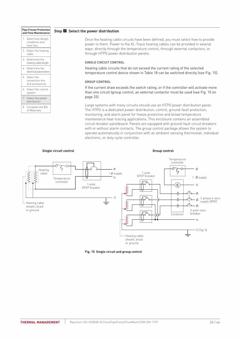
Pipe Freeze Protectionand Flow Maintenance Step Select the power distribution
Once the heating cable circuits have been defined, you must select how to provide power to them. Power to the XL-Trace heating cables can be provided in several ways: directly through the temperature control, through external contactors, or through HTPG power distribution panels.
SINGLE CIRCUIT CONTROL
Heating cable circuits that do not exceed the current rating of the selected temperature control device shown in Table 18 can be switched directly (see Fig . 15) .
GROUP CONTROL
If the current draw exceeds the switch rating, or if the controller will activate more than one circuit (group control, an external contactor must be used (see Fig . 15 on page 33) .
Large systems with many circuits should use an HTPG power distribution panel. The HTPG is a dedicated power-distribution, control, ground-fault protection, monitoring, and alarm panel for freeze protection and broad temperature maintenance heat-tracing applications. This enclosure contains an assembled circuit-breaker panelboard. Panels are equipped with ground-fault circuit breakers with or without alarm contacts. The group control package allows the system to operate automatically in conjunction with an ambient-sensing thermostat, individual electronic, or duty cycle controller.
Fig. 15 Single circuit and group control
Single circuit control Group control
Temperaturecontroller
1-poleGFEP breaker
1N
G
Heatingcable
øø supply
C
Temperaturecontroller
Contactor
1-poleGFEP breaker
N
G (Typ 3)
ø2
ø1
ø3
3-phase 4-wiresupply (WYE)
3-pole mainbreaker
ø
ø 1 supply
N
Heating cable sheath, braid or ground
Heating cable sheath, braid or ground
33 / 44THERMAL MANAGEMENT Raychem-DG-H55838-XLTracePipeFreezeFlowMaintCOM-EN-1707

Fig. 16 HTPG power distribution panel
Fig. 17 HTPG power schematic
A
COMMON ALARMPUSH TO ACKNOWLEDGE
HAND/OFF/AUTO
1
2
3
4
5
6
7
8
9
10
11
12
Main circuitbreaker
Maincontactor
Distributionpanelboard
Fuse holder
C
POWER ON
TB 1
TB 2
ARR
Groundbus bar
Selector switch
Alarm relay(optional)
Terminals(optional)
Push button for light testing
Alarm horn (optional)
Alarm option shown above
Doordisconnect(optional)
NØ1Three-pole main
circuit breaker
Panelenergized
Contactorcoil
C NC
External controller/thermostat*
Hand AutoOff
Three-pole maincontactor
Ø3Ø2
Power connection
Heating cable
One-pole with 30-mAground-fault trip
(120/277 Vac)
Two-pole with 30-mAground-fault trip
(208/240 Vac)
Alarmremoteannunciation(with alarm option)
Heating cablecircuit
Heating cablecircuit
G
End seal
Heating cable shealth, braid or ground
Three-phase, 4 wire supply (Wye)
PIPE FREEZE PROTECTION AND FLOW MAINTENANCE — XL-TRACE SYSTEM
34 / 44 THERMAL MANAGEMENTRaychem-DG-H55838-XLTracePipeFreezeFlowMaintCOM-EN-1707
TAbLE 19 POWER DISTRIbUTIONCatalog number Description
Power Distribution
A
COMMON ALARMPUSH TO ACKNOWLEDGE
HAND/OFF/AUTO
C
POWER ON
HTPG Heat-tracing power distribution panel with ground-fault and monitoring for group control.
2. Select the heating cable
3. Determine the heating cable length
4. Determine the electrical parameters
5. Select the connection kits and accessories
6. Select the control system
7. Select the power distribution
8. Complete the Bill of Materials
Pipe Freeze Protectionand Flow Maintenance
1. Determine design conditions and heat loss
Pipe Freeze Protectionand Flow Maintenance
Step Complete the bill of Materials
If you used the Design Worksheet to document all your design parameters, you should have all the details necessary complete your Bill of Materials.
35 / 44THERMAL MANAGEMENT Raychem-DG-H55838-XLTracePipeFreezeFlowMaintCOM-EN-1707

XL-TRACE SYSTEM PIPE FREEZE PROTECTION AND FLOW MAINTENANCE DESIGN WORKSHEET
Step Determine design conditions and pipe heat lossDesign conditions
XL-Trace application Location
Maintain temp.(Tm)
Max. system temp.(Tmax)
Min. ambient temp.(Ta)
Pipe diameter and material
Pipe length
Thermal insulation type and thickness
Pipe freeze protection❑ Water piping ❑ Indoors
❑ Outdoors❑ Aboveground❑ Buried ______ ______ ______ ____ in
❑ Metal❑ Plastic ____ ft (m)
❑ Fiberglass❑ ________ ___ in
Flow maintenance❑ Grease waste lines
❑ Indoors❑ Outdoors
❑ Aboveground❑ Buried ______ ______ ______ ____ in
❑ Metal❑ Plastic ____ ft (m)
❑ Fiberglass❑ ________ ___ in
❑ Fuel lines ❑ Indoors❑ Outdoors
❑ Aboveground❑ Buried ______ ______ ______ ____ in
❑ Metal❑ Plastic ____ ft (m)
❑ Fiberglass❑ ________ ___ in
Example:0 Water piping 0 Aboveground
0 Outdoor 40°F 80°F –20°F 2 in 0 Plastic 300 ft 0 Fiberglass 1 in
Pipe heat lossCalculate temperature differential ΔT
Pipe maintain temperature (TM)°F (°C)
Ambient temperature (TA)°F (°C)
TM ∆T− =
Example: Pipe Freeze Protection − Water Piping
TA
Pipe maintain temperature (TM)°F
(from Step 1)
(from Step 1) Ambient temperature (TA)°F
TM ∆T
40 °F
40 °F
−20 °F
−20 °F 60 °F− =
TA
PIPE FREEZE PROTECTION AND FLOW MAINTENANCE — XL-TRACE SYSTEM
36 / 44 THERMAL MANAGEMENTRaychem-DG-H55838-XLTracePipeFreezeFlowMaintCOM-EN-1707

Determine the pipe heat loss: See Table 2 for the base heat loss of the pipe (Qb). If the ΔT for your system is not listed, interpolate between the two closest values.
QB-50 ∆T1W/ft (W/m)
QB-100 ∆T2W/ft (W/m)
QB W/ft (W/m)
in
in
°F (°C)
W/ft (W/m)
W/ft (W/m)
Example: Pipe Freeze Protection − Water Piping
Pipe diameter 2 in
1 in
60°F Insulation thickness
3.2 W/ft
6.8 W/ft
∆T
QB-50
QB-100
Pipe diameter
Insulation thickness
∆T
QB-50
QB-50
∆T 60°F is 20% of the distance between ∆T 50°F and ∆T 100°FQB-50 + [0.20 x (QB-100 − QB-50)]
∆T interpolation
3.2 + [0.20 x (6.8 − 3.2)] = 3.9 W/ftQB-60
3.9 W/ft @ TM 40°FPipe heat loss (QB-60)
37 / 44THERMAL MANAGEMENT Raychem-DG-H55838-XLTracePipeFreezeFlowMaintCOM-EN-1707

Compensate for insulation type and pipe locationSee Table 2 for the pipe heat loss (Qb). If the ΔT for your system is not listed, interpolate between the two closest values.See Table 3 for indoor multiple See Table 4 for insulation multiple
QB
QCORRECTEDQB
x =
W/ft (W/m)
Insulation multiple
Indoor multiple (if applicable)
Location
Insulation thickness and type
Insulation multiplex
Indoor multiple(if applicable)
Example: Pipe Freeze Protection − Water Piping
Location Aboveground, indoor
1-in fiberglassThermal insulation thickness and type
3.9 W/ft @ TM 40°F
Indoor multiple
1.00Insulation multiple
N/A
3.9 W/ft 1.00 3.9 W/ft @ TM 40°FQCORRECTED QB
x = =Insulation multiple
QB
PIPE FREEZE PROTECTION AND FLOW MAINTENANCE — XL-TRACE SYSTEM
38 / 44 THERMAL MANAGEMENTRaychem-DG-H55838-XLTracePipeFreezeFlowMaintCOM-EN-1707

Step Select the heating cablePower output data: See Fig. 12Power output correction factors: See Table 5Heating cable temperature ratings: See Table 6
Select outer jacket❑ -CR❑ -CTExample: Pipe Freeze Protection – Water Piping5XL1-CR
Power at rated V factorx
Pipe maintain temperature (TM) (from Step 1)
(from Step 1)
(from Step 1)
(from Step 1)
(from Step 1)
(from Step 1)
(from Step 1)
(from Step 1)
Corrected heat loss (QCORRECTED)
Supply voltage
Pipe material (metal or plastic)
XL-Trace application (water, fuel oil, or greasy waste)
Pipe freeze protection: general water piping, sprinkler piping
Flow maintenance: greasy waste lines, fuel lines
Maximum system use temperature (TMAX)
Plastic pipe correction factor=
Corrected power
Heating cable selected
Power at TM (120/208 V)
Power output correction factor
Plastic pipe correction factor
Is the heating cable power output (PCORRECTED) ≥ the corrected heat loss?
If No, then design with additional runs of heating cable or thicker thermal insulation.
YesE NoE
Maintain temperature (TM) 40°F
3.9 W/ft @ TM 40°F
120 V
plastic
QB = 3.9 W/ft @ TM 40°FSelect curve C: 5XL1 = 5.6 W/ft @ 40°FPower output correction factor: 120 V = 1.00Pipe material correction factor: Plastic = 0.75Corrected heating cable power: 5.6 @/ft x 1.00 x 0.75 = 4.2 W/ftSelect: 5XL1Maximum system temperature (TMAX): 80°FMaximum heating cable exposure temperature (TEXP): 150°FTMAX < TEXP: Yes
Corrected heat loss (QCORRECTED)
Supply voltage
Pipe material (metal or plastic*) (*AT-180 aluminum tape required for installing heating cable on plastic pipes)
Example: Pipe Freeze Protection − Water Piping
39 / 44THERMAL MANAGEMENT Raychem-DG-H55838-XLTracePipeFreezeFlowMaintCOM-EN-1707

Step Determine the heating cable lengthFor additional heating cable allowance for valves: See Table 7.For additional heating cable allowance for pipe supports and flanges: See Table 8.
Pipe length( )x +
Total heating cablelength required
Number of heatingcable runs
Total heating cable length
Heat sinks
=Additional cable for valves,pipe supports, and flanges
Type of valvesx
Total heating cablefor valves
How many=
Additional heating cable
Type of pipe supportsx
Total heating cablefor pipe supports
How many=
Additional heating cable*2-in pipe diameter = 0.17 ft
Type of flangesx
Total heating cablefor flanges
How many=
Additional heating cable
Total heating cable for heat sinks:
Pipe length( )x +
Total heating cablelength required
300 ft 1 15 ft 315 ft
Number of heatingcable runs
Total heating cable length
Heat sinks
=Additional cable for valves,pipe supports, and flanges
Type of valvesx
Total
Gate valves 3 4.3 ft 12.9 ft
How many=
Additional heating cable
Example:
Type of pipe supportsx
Total
Pipe hangers noninsulatedand U-bolt supports 5 (0.17 ft* x 2 = 0.34 ft) 1.7 ft
How many=
Additional heating cable*2-in pipe diameter = 0.17 ft
Type of flangesx
Total
n/a 0 0 0 ft
How many=
Additional heating cable
14.6 ft rounded up to 15 ftTotal:
PIPE FREEZE PROTECTION AND FLOW MAINTENANCE — XL-TRACE SYSTEM
40 / 44 THERMAL MANAGEMENTRaychem-DG-H55838-XLTracePipeFreezeFlowMaintCOM-EN-1707

Step Determine the electrical parametersDetermine maximum circuit length and number of circuitsSee Table 9 and Table 10.
Determine transformer loadSee Table 11 and Table 12.
201 ft315 ft 1.6 circuits, round up to 2
315 ft of 5XL1-CR
−20°F
201 ft
/ =Number of circuitsMaximum heating cable circuit lengthTotal heating cable length required
T 120 V T 208 VT 240 V T 277 V
Total heating cable length required
Supply voltage:
T 15 A T 20 AT 30 A T 40 A
Circuit breaker size:
Minimum start-up temperature
Maximum circuit length
/ =Number of circuitsMaximum heating cable circuit lengthTotal heating cable length required
T 120 V T 208 VT 240 V T 277 V
Total heating cable length required
Supply voltage:
T 15 A T 20 AT 30 A T 40 A
Circuit breaker size:
Minimum start-up temperature
Maximum circuit length
Example:
9
9
x / 1000 =Transformer
load (kW)
0.119 A/ft 315 ft 120 V 4.5 kW
Max A/ft at minimum start-up temperature Heating cable lengthx
Supply voltage
Example:
x / 1000 =Transformer
load (kW)Max A/ft at minimum start-up temperature Heating cable length
xSupply voltage
41 / 44THERMAL MANAGEMENT Raychem-DG-H55838-XLTracePipeFreezeFlowMaintCOM-EN-1707

Step Select the connection kits and accessories See Table 13.
Connection kits – Aboveground Description QuantityHeating cable allowance
❑ RayClic-PC
❑ RayClic-PS
❑ RayClic-PT
❑ FTC-P
❑ RayClic-S
❑ RayClic-T
❑ RayClic-X
❑ FTC-HST
❑ FTC-PSK
❑ RayClic-LE
❑ RayClic-E
Power connection and end seal
Power splice and end seal
Powered tee and end seal
Power connection and end seal
Splice
Tee kit with end seal
Cross connection
Low-profile splice/tee
Pipe stand and power connection kit
Lighted end seal
Extra end seal
____________
____________
____________
____________
____________
____________
____________
____________
____________
____________
____________
__________________
__________________
__________________
__________________
__________________
__________________
__________________
__________________
__________________
__________________
__________________
Connection kits – buried Description QuantityHeating cable allowance
❑ RayClic-PC
❑ FTC-XC
❑ RayClic-LE
❑ RayClic-E
Power connection and end seal
Power splice and end seal
Lighted end seal
Extra end seal
____________
____________
____________
____________
__________________
__________________
__________________
__________________
Accessories – Aboveground and buried Description Quantity
❑ RayClic-SB-04
❑ RayClic-SB-02
❑ ETL
❑ GT-66
❑ GS-54
❑ AT-180
Pipe mounting bracket
Wall mounting bracket
“Electric-Traced” label
Glass cloth adhesive tape
Glass cloth adhesive tape
Aluminum tape (for plastic pipes)
_____________
_____________
_____________
_____________
_____________
_____________
+ =Total heating cable
length requiredTotal heating cable allowance for connection kitsTotal heating cable length
Total heating cableallowance for connection kits
PIPE FREEZE PROTECTION AND FLOW MAINTENANCE — XL-TRACE SYSTEM
42 / 44 THERMAL MANAGEMENTRaychem-DG-H55838-XLTracePipeFreezeFlowMaintCOM-EN-1707

Step Select the control system See Table 18.
Thermostats, controllers and accessories Description Quantity
❑ ECW-GF
❑ ECW-GF-DP
❑ C910-485
❑ ACS-UIT2
❑ ACS-PCM2-5
❑ ProtoNode-RER
❑ RTD3CS
❑ RTD10CS
❑ RTD-200
❑ RTD50CS
Electronic thermostat with 25-ft sensor
Remote display panel for ECW-GF
Microprocessor-based single-point heat-tracing controller
ACS-30 user interface terminal
ACS-30 power control panel
Multi-protocol gateway
Resistance temperature device
Resistance temperature device
Resistance temperature device
Resistance temperature device
_____________
_____________
_____________
_____________
_____________
_____________
_____________
_____________
_____________
_____________
Step Select the power distribution See Table 19.
Power distribution Description Quantity
❑ HTPG Heat-tracing power distribution panel for group control _____________
Step Complete the bill of MaterialsUse the information recorded in this worksheet to complete the Bill of Materials.
43 / 44THERMAL MANAGEMENT Raychem-DG-H55838-XLTracePipeFreezeFlowMaintCOM-EN-1707

NORTH AMERICA Tel: +1.800.545.6258Fax: +1.800.527.5703Tel: +1.650.216.1526Fax: [email protected]
Pentair is owned by Pentair or its global affiliates. All other trademarks are the property of their respective owners. Pentair reserves the right to change specifications without prior notice.
© 2009-2017 Pentair.
WWW.PENTAIRTHERMAL.COM
44 / 44THERMAL MANAGEMENT Raychem-DG-H55838-XLTracePipeFreezeFlowMaintCOM-EN-1707