pipe freeze protection design/install guide - drexan … - pipe fre… · · 2015-06-09pipe...
TRANSCRIPT

HD100707-1 Rev0
Page 1 of 16
Pipe Freeze Protection
Design/Install Guide

HD100707-1 Rev0
Page 2 of 16
Pipe Freeze Protection
Design / Install Guide
CONTENTS
Introduction Page 3
STEP 1 – Information Required Page 4
STEP 2 – Design Considerations Page 5
STEP 3 – Electrical Requirements Page 6
STEP 4 – Selecting Cable Page 6
STEP 5 – Cable Components Page 10
STEP 6 – Monitoring and Control Page 12
Installing Self Regulating Cable Page 13
Testing Self Regulating Cable Page 14
Cable Test Report Template Page 15
Troubleshooting Self Regulating Cable Page 16

HD100707-1 Rev0
Page 3 of 16
INTRODUCTION
Drexan HeatTracer products are designed to serve the most demanding environments including hazardous and non-hazardous areas, as well as areas where corrosive exposure may be of concern.
PipeGuard® is certified to; CSA (CUS) standards for use throughout North America, ATEX for Europe, and is suitable for both metal and non-metal pipes, tanks and vessels.
The integrity of a heat tracing system depends upon on how accurately the cable is selected and how well it is installed. An improperly designed and installed heat tracing system could result in cable failure and possible physical injury.
The following instructions will provide you with a step-by-step procedure for determining the best solution for your freeze protection applications.
Drexan HeatTracer web-based design program is available at www.pro-trace.com

HD100707-1 Rev0
Page 4 of 16
STEP 1 – INFORMATION REQUIRED
Pipe diameter
Pipe length
Minimum ambient temperature This is the minimum temperature expected (worst case) throughout the winter months.
Maintain temperature For freeze protection a typical maintain temperature of 5˚C (40˚F) is sufficient.
For process temperatures ensure the temperature rating of the cable is suitable.
Cable ratings: Refer to the respective cable data sheets available at www.drexanheattracer.com.
Start-up temperature This temperature will have a direct effect on the maximum circuit length and the breaker size required. You should select the temperature at which the cable will normally become energized, not necessarily the coldest temperature.
Metal or non-metallic Pipe Some materials have superior heat transfer compared to others. Metal for example will conduct heat better than a polymeric material. For this reason we recommend the use of aluminum foil tape (part # TAPE-AL) on polymeric pipes applied over the pipe under the cable.
Pipe hardware (valves, shoes, flanges etc.) When measuring the total length of the pipe to be heat-traced remember to allow extra cable for the pipe hardware.
Thermal Insulation type & thickness All pipes, equipment and pipe hardware must be thermally insulated.
Measurement: Metric? Imperial? Temperature: Celsius? Fahrenheit?
Voltage: (include if 3 phase) _____________
Applications
Pipe Tracing: Metal? Other? (specify) _______
Pipe Length: Diameter: Insulation Type:
Insulation Thickness: Not Yet Determined:
Low Ambient Temp: Max. Pipe Temp: Maintain Temp:
Area Classification: Class Div. Group
Number of Supports Valves Hangers

HD100707-1 Rev0
Page 5 of 16
STEP 2 – DESIGN CONSIDERATIONS
When a pipe enters a building it is important that the cable extends into the building approximately 12” to ensure the pipe temperature is maintained above freezing.
When a pipe enters the ground to below the frost line it is important to run the cable well below the frost line to ensure the pipe temperature is maintained above freezing.
When a main pipe has a short branch line connected to it, the branch line may be double traced (down & back) to eliminate the need for a Tee Splice Kit.
Heating cable should not pass through the air. When crossing from one pipe to another, the cable should run through a Flexible Extension (part # FLEX-E)
Select the cable wattage output to suit the application. A conservative design will allow a slightly higher wattage output, per foot of cable, than required.
Insulate all heat sinks in the heat tracing system. Allow sufficient cable to trace additional heat sinks. See Table 4
DO NOT expose heating cables to temperatures higher than their temperature ratings.
For valves, install the heating cable so that the valves can be conveniently removed for servicing.
The type and thickness of thermal insulation will have a direct effect on the amount of heat required. Longer circuit lengths may be achieved by increasing the insulating thermal value to lower the cable wattage output required. Refer to Table 3
Multiple runs of cable may be required on larger pipes with high heat loss.
When using a spray-on insulation it is recommended that a layer of aluminum foil tape be placed over the cable to prevent embedding of the cable in the thermal insulation, thereby resulting in poor heat transfer from the cable to the pipe.
If lines are steam cleaned, pay particular attention to the maximum exposure temperature, even if the heating application is freeze protection. Standard freeze protection cables will fail if exposed to low pressure steam. Specify either PipeGuard Hot or PipeGuard CMH cables in these applications.
HD100707-1 Rev0
Page 6 of 16
STEP 3 – ELECTRICAL REQUIREMENTS
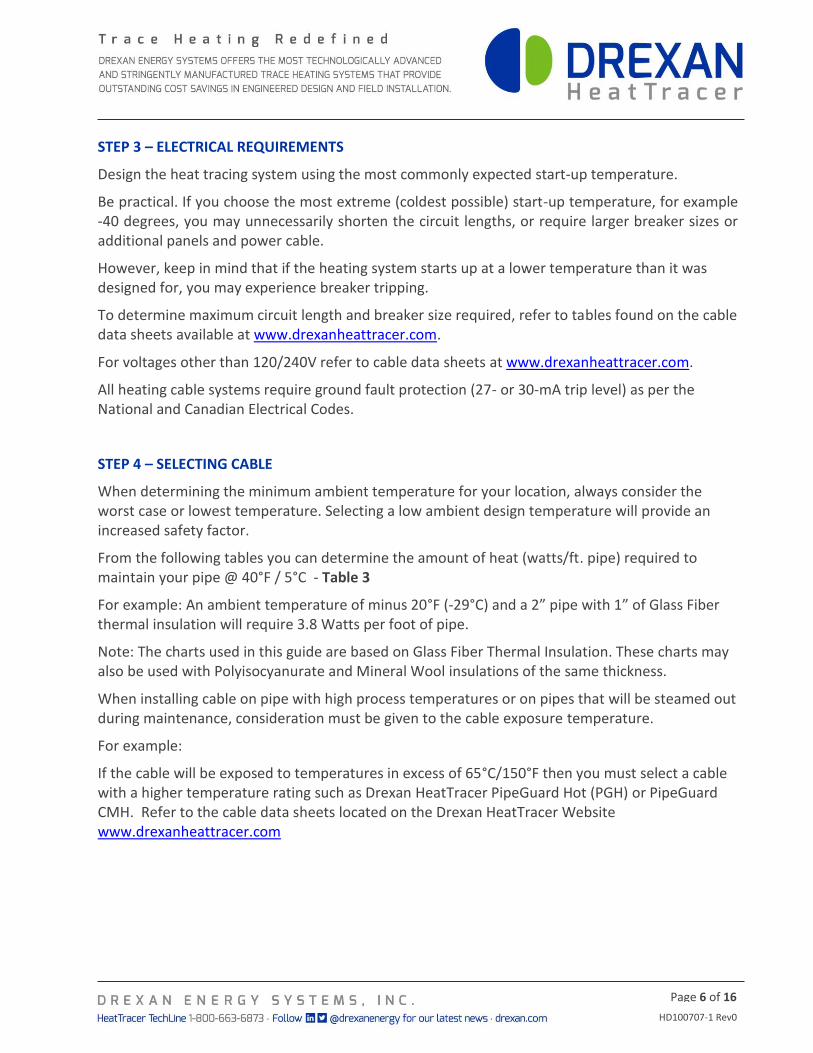
Design the heat tracing system using the most commonly expected start-up temperature.
Be practical. If you choose the most extreme (coldest possible) start-up temperature, for example -40 degrees, you may unnecessarily shorten the circuit lengths, or require larger breaker sizes or additional panels and power cable.
However, keep in mind that if the heating system starts up at a lower temperature than it was designed for, you may experience breaker tripping.
To determine maximum circuit length and breaker size required, refer to tables found on the cable data sheets available at www.drexanheattracer.com.
For voltages other than 120/240V refer to cable data sheets at www.drexanheattracer.com.
All heating cable systems require ground fault protection (27- or 30-mA trip level) as per the National and Canadian Electrical Codes.
STEP 4 – SELECTING CABLE
When determining the minimum ambient temperature for your location, always consider the worst case or lowest temperature. Selecting a low ambient design temperature will provide an increased safety factor.
From the following tables you can determine the amount of heat (watts/ft. pipe) required to maintain your pipe @ 40°F / 5°C - Table 3
For example: An ambient temperature of minus 20°F (-29°C) and a 2” pipe with 1” of Glass Fiber thermal insulation will require 3.8 Watts per foot of pipe.
Note: The charts used in this guide are based on Glass Fiber Thermal Insulation. These charts may also be used with Polyisocyanurate and Mineral Wool insulations of the same thickness.
When installing cable on pipe with high process temperatures or on pipes that will be steamed out during maintenance, consideration must be given to the cable exposure temperature.
For example:
If the cable will be exposed to temperatures in excess of 65°C/150°F then you must select a cable with a higher temperature rating such as Drexan HeatTracer PipeGuard Hot (PGH) or PipeGuard CMH. Refer to the cable data sheets located on the Drexan HeatTracer Website www.drexanheattracer.com

HD100707-1 Rev0
Page 7 of 16
Table 3
WATTS PER FT. PIPE REQUIRED
Pipe Dia. Ambient Temp. Insulation Thickness
Inch °F °C ½" 1" 1 ½" 2" 2 ½" 3" 4"
½
0 -18 2 1.3 1 1 1 0.8 0.7
-10 -23 2.5 1.6 1.3 1.2 1 1 0.8
-20 -29 2.9 2 1.6 1.4 1.2 1 1
-40 -40 3.9 2.5 2 1.8 1.6 1.5 1.3
¾
0 -18 2.3 1.5 1.2 1 1 0.8 0.7
-10 -23 2.9 1.9 1.5 1.3 1 1 0.9
-20 -29 3.5 2.2 1.8 1.5 1.4 1.3 1
-40 -40 4.5 2.9 2.3 2 1.8 1.6 1.4
1
0 -18 2.8 1.7 1.4 1.2 1 1 0.8
-10 -23 3.4 2.1 1.7 1.4 1.3 1.2 1
-20 -29 4.1 2.5 2 1.7 1.5 1.4 1.2
-40 -40 5.3 3.3 2.6 2.2 2 1.8 1.6
1 ¼
0 -18 3.3 2 1.6 1.3 1 1.1 0.9
-10 -23 4.1 2.5 2 1.6 1.4 1.3 1.1
-20 -29 4.9 3 2.3 1.9 1.7 1.6 1.3
-40 -40 6.4 3.9 3 2.5 2.2 2 1.8
1 ½
0 -18 3.7 2.2 1.7 1.4 1.3 1.1 1
-10 -23 4.5 2.7 2.1 1.8 1.5 1.4 1.2
-20 -29 5.4 3.3 2.5 2 1.8 1.7 1.4
-40 -40 7.1 4.3 3.3 2.7 2.4 2.2 1.9
2
0 -18 4.4 2.6 2 1.6 1.4 1.3 1.1
-10 -23 5.5 3.2 2.4 2 1.8 1.6 1.4
-20 -29 6.5 3.8 2.9 2.4 2.1 1.9 1.6
-40 -40 8.6 5 3.8 3.1 2.7 2.5 2.1
2 ½
0 -18 5.2 3 2.3 1.8 1.6 1.4 1.2
-10 -23 6.4 3.7 2.8 2.3 2 1.8 1.5
-20 -29 7.6 4.4 3.3 2.7 2.4 2.1 1.8
-40 -40 10 5.8 4.3 3.6 3 2.8 2.3
3
0 -18 6.1 3.5 2.6 2.1 1.8 1.6 1.4
-10 -23 7.6 4.3 3.2 2.6 2.3 2 1.7
-20 -29 9 5.2 3.8 3 2.7 2.4 2
-40 -40 11.9 6.8 5 4 3.5 3.1 2.6
4
0 -18 7.6 4.3 3.1 2.5 2.2 1.9 1.6
-10 -23 9.5 5.3 3.9 3.1 2.7 2.3 1.9
-20 -29 11.3 6.3 4.6 3.7 3.2 2.8 2.3
-40 -40 14.9 8.3 6 4.9 4.1 3.7 3
HD100707-1 Rev0
Page 8 of 16
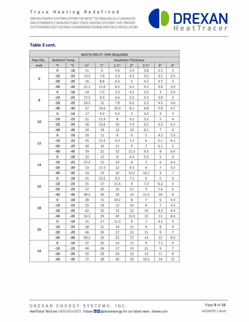
Table 3 cont.
WATTS PER FT. PIPE REQUIRED
Pipe Dia. Ambient Temp. Insulation Thickness
Inch °F °C ½" 1" 1 ½" 2" 2 ½" 3" 4"
6
0 -18 11 6 4.6 3.4 2.8 2.5 2
-10 -23 13.5 7.4 5.3 4.2 3.5 3.1 2.5
-20 -29 16 8.8 6.3 5 4.2 3.7 3
-40 -40 21.1 11.6 8.2 6.5 5.5 4.8 3.9
8
0 -18 14 7.5 5.3 4.2 3.5 3 2.4
-10 -23 17.2 9.3 6.6 5.2 4.3 3.8 3
-20 -29 20.5 11 7.8 6.2 5.2 4.5 3.6
-40 -40 27 14.6 10.3 8.1 6.8 5.9 4.7
10
0 -18 17 9.2 6.4 5 4.2 4 3
-10 -23 21 11.4 8 6.2 5.2 5 4
-20 -29 26 13.6 10 7.4 6.2 5.3 4.2
-40 -40 34 18 13 10 8.1 7 6
12
0 -18 20 11 8 6 5 4.2 3.3
-10 -23 25 13.3 9.3 7.2 6 5.1 4.1
-20 -29 30 16 11 9 7 6.1 5
-40 -40 39 21 15 11.3 9.3 8 6.4
14
0 -18 22 12 8 6.3 5.2 5 4
-10 -23 27.2 15 10 8 7 6 4.4
-20 -29 33 17.3 12 9.3 8 7 5.2
-40 -40 43 23 16 12.2 10.1 9 7
16
0 -18 25 13.2 9.2 7.1 6 5 4
-10 -23 31 17 11.4 9 7.3 6.2 5
-20 -29 37 20 14 11 9 7.4 6
-40 -40 48.5 26 18 14 11.3 10 8
18
0 -18 28 15 10.2 8 7 6 4.3
-10 -23 35 19 13 10 8 7 5.4
-20 -29 42 22 15 12 10 8.2 6.4
-40 -40 54.3 29 20 15.3 13 11 8.4
20
0 -18 31 17 11.3 9 7 6.1 5
-10 -23 38 21 14 11 9 8 6
-20 -29 46 24 17 13 11 9 7
-40 -40 60.2 32 22 17 14 12 9.2
24
0 -18 37 20 14 11 9 7.1 6
-10 -23 46 24 17 13 11 9 7
-20 -29 55 29 20 15 13 11 8
-40 -40 72 38 26 20 16.3 14 11
HD100707-1 Rev0
Page 9 of 16
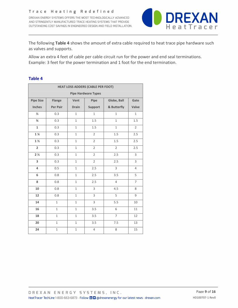
The following Table 4 shows the amount of extra cable required to heat trace pipe hardware such as valves and supports.
Allow an extra 4 feet of cable per cable circuit run for the power and end seal terminations. Example: 3 feet for the power termination and 1 foot for the end termination.
Table 4
HEAT LOSS ADDERS (CABLE PER FOOT)
Pipe Hardware Types
Pipe Size
Inches
Flange
Per Pair
Vent
Drain
Pipe
Support
Globe, Ball
& Butterfly
Gate
Valve
½ 0.3 1 1 1 1
¾ 0.3 1 1.5 1 1.5
1 0.3 1 1.5 1 2
1 ¼ 0.3 1 2 1.5 2.5
1 ½ 0.3 1 2 1.5 2.5
2 0.3 1 2 2 2.5
2 ½ 0.3 1 2 2.5 3
3 0.3 1 2 2.5 3
4 0.5 1 2.5 3 4
6 0.8 1 2.5 3.5 5
8 0.8 1 2.5 4 7
10 0.8 1 3 4.5 8
12 0.8 1 3 5 9
14 1 1 3 5.5 10
16 1 1 3.5 6 11
18 1 1 3.5 7 12
20 1 1 3.5 7.5 13
24 1 1 4 8 15
HD100707-1 Rev0
Page 10 of 16
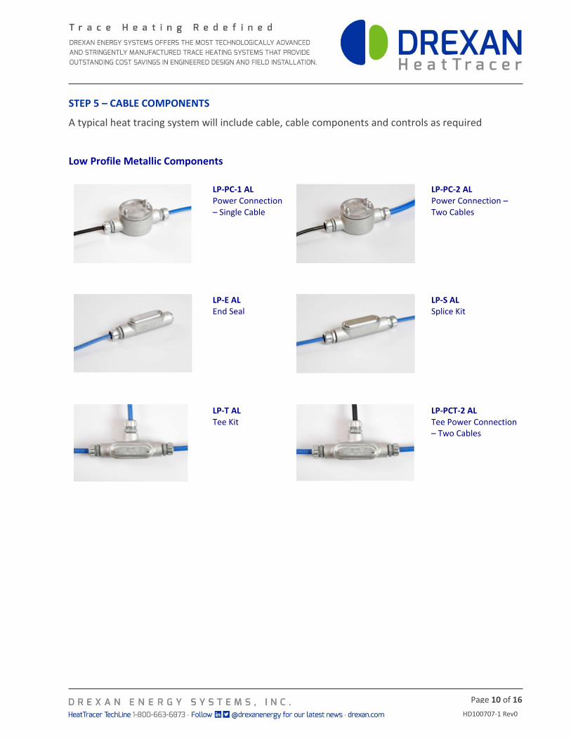
STEP 5 – CABLE COMPONENTS A typical heat tracing system will include cable, cable components and controls as required
Low Profile Metallic Components
LP-PC-1 AL Power Connection – Single Cable
LP-PC-2 AL Power Connection – Two Cables
LP-E AL End Seal
LP-S AL Splice Kit
LP-T AL Tee Kit
LP-PCT-2 AL Tee Power Connection – Two Cables

HD100707-1 Rev0
Page 11 of 16
High Profile Components
Heat Shrink® Components
HS-PC Power Connection (Junction box not included)
HS-TSPLICE Splice Kit
HS-ESK End Seal Kit
HS-JB Junction Box
PowerPod® Components
PP-PC-HL (Hazardous) & PP-PC-OL (Ordinary)
PowerPod Power Connection and Splice Kit allows a power supply to one heating cable (power to heater) or a splice between two heating cables (heater to heater).
PP-RE-L
PowerPod Re-enterable End Seal is an above thermal insulation end seal designed for repeated use and entry should cable modification be required in the field.
HP-PC-1 AL Power Connection – Single Cable
HP-LE-1R/HP-LE-2R Lighted End Seal 120V/277V
HP-LEA-1R/HP-LEA-2R Adapter Kits - Light Enclosure Only (for use with LP-E AL Kit)
HD100707-1 Rev0
Page 12 of 16
STEP 6 – MONITORING AND CONTROL
Select the thermostat or control device that best suits your application. The method of control can range from simple mechanically switched thermostats, electronic control and monitoring systems or ambient air sensing control.
Mechanical
STAT-LS-40F The STAT-LS-40F thermostat is ideal for applications where freeze protection or lower-range temperature control is critical. In cold climates the thermostat switches heating devices that prevent pipes, valves, tanks and fittings from freezing. This thermostat can be used in ambient-sensing applications by placing the sensor in the air or as a line-sensing thermostat by securing the bulb to the pipe or tank. It can be used as a single circuit control or as a pilot control for several circuits by switching a contactor. Set point at factory is 40 °F/5°C.
STAT-LS-ADJ The STAT-LS-ADJ thermostat is ideal for applications where freeze protection or lower-range temperature control is critical. In cold climates this thermostat switches heating devices that prevent pipes, valves, tanks and fittings from freezing. This thermostat can be used in ambient-sensing applications by placing the sensor in the air or as a line-sensing thermostat by securing the bulb to the pipe or tank. It can be used as a single circuit control or as a pilot control for several circuits by switching a contactor.
STAT-TXR-ADJ The STAT-TXR-ADJ thermostat is ideal for applications where freeze protection or temperature control in hazardous locations is critical. This thermostat can be used in ambient-sensing applications by placing the sensor in the air or as a line-sensing thermostat by securing the bulb to the pipe or tank.
The STAT-TXR-ADJ can be used as a single circuit control or as a pilot control for several circuits by switching a contactor.
Electronic
TRACEMATE and TRACEMATE II CTR
The TraceMate™ family of electronic controls is designed for indoor or outdoor use in general purpose non-hazardous and hazardous Class I Division 2 / Zone 2 areas.
TraceMate™ comes complete with a built in Ground Fault Protection Device (GFPD) eliminating the need for a separate ground fault breaker.
HD100707-1 Rev0
Page 13 of 16
INSTALLING SELF REGULATING CABLE
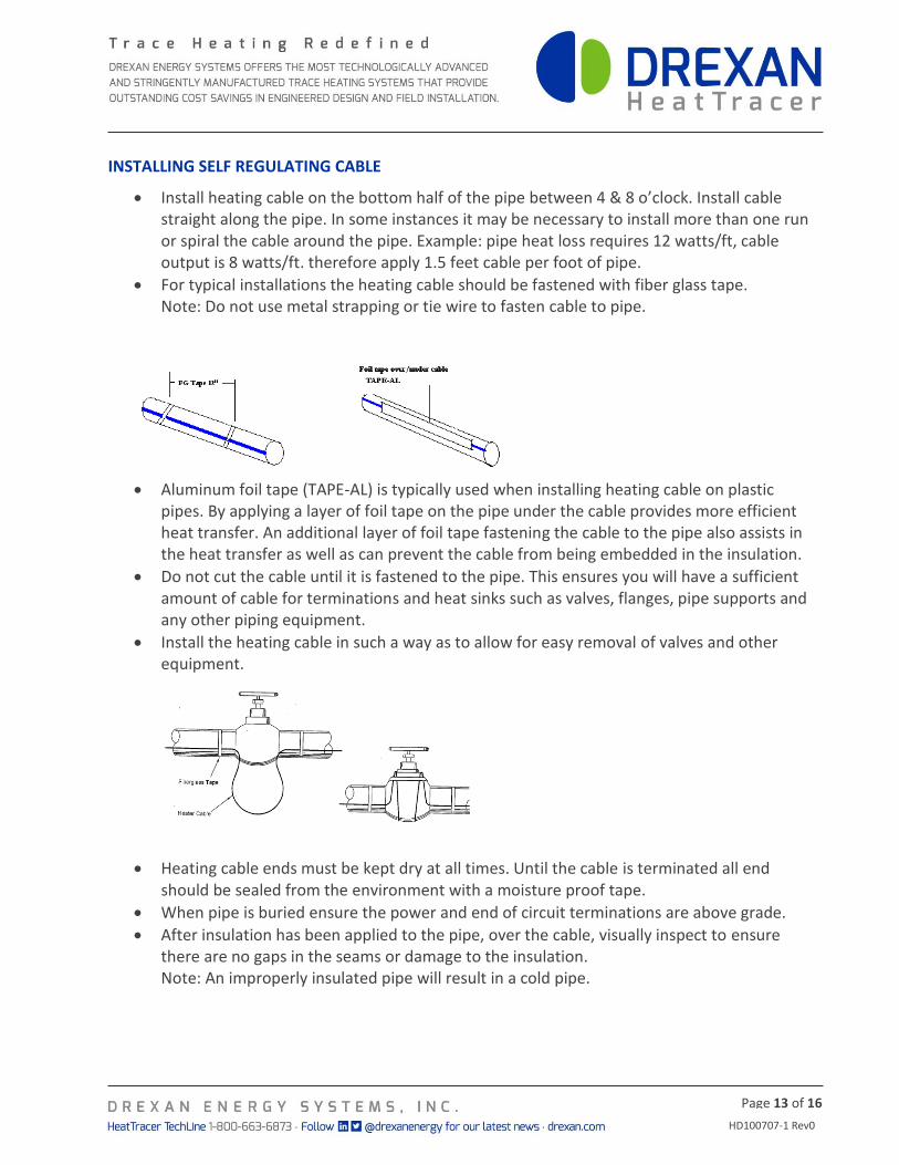
Install heating cable on the bottom half of the pipe between 4 & 8 o’clock. Install cable straight along the pipe. In some instances it may be necessary to install more than one run or spiral the cable around the pipe. Example: pipe heat loss requires 12 watts/ft, cable output is 8 watts/ft. therefore apply 1.5 feet cable per foot of pipe.
For typical installations the heating cable should be fastened with fiber glass tape. Note: Do not use metal strapping or tie wire to fasten cable to pipe.
Aluminum foil tape (TAPE-AL) is typically used when installing heating cable on plastic pipes. By applying a layer of foil tape on the pipe under the cable provides more efficient heat transfer. An additional layer of foil tape fastening the cable to the pipe also assists in the heat transfer as well as can prevent the cable from being embedded in the insulation.
Do not cut the cable until it is fastened to the pipe. This ensures you will have a sufficient amount of cable for terminations and heat sinks such as valves, flanges, pipe supports and any other piping equipment.
Install the heating cable in such a way as to allow for easy removal of valves and other equipment.
Heating cable ends must be kept dry at all times. Until the cable is terminated all end should be sealed from the environment with a moisture proof tape.
When pipe is buried ensure the power and end of circuit terminations are above grade.
After insulation has been applied to the pipe, over the cable, visually inspect to ensure there are no gaps in the seams or damage to the insulation. Note: An improperly insulated pipe will result in a cold pipe.

HD100707-1 Rev0
Page 14 of 16
TESTING SELF-REGULATING CABLE
A test should be performed when the heating cable is received, prior to installation and after installation using a 500 VDC megger.
Note: Do not use a megger in excess of 2500 VCD.
Detecting cable damage prior to the application of insulation can prevent additional labor costs.
Minimum readings of 20 Megohms for each circuit is an acceptable level to test for.
A record should be kept of the reading after the cable has been installed. This reading can be used as a reference point when taking future readings during regular maintenance.
A history of resistance readings can be useful in spotting moisture ingression into the cable from either junction boxes or physical damage to the cable.
See the following page for a “Test Report” template.

HD100707-1 Rev0
Page 15 of 16
HEATING CABLE TESTING REPORT
Customer ___________________________ Contractor
Phone No. __________________________ Phone No. _
Site Location ________________________ Project Ref.
Readings Prior to Installation:
Cable Reference No ___________________ Heater Length
Insulation Resistance (M Ohms) __________________
Tested By ___________________________ Date
Witnessed By ________________________ Date
Readings after Installation:
Insulation Resistance (M Ohms) ______________________________________
Tested By ___________________________ Date
Witnessed By ________________________ Date
Final Readings:
Insulation Resistance (M Ohms) ______________________________________
Panel No. ___________________________ Breaker No.
Ambient Temp ___________ Volts Amps ____________
Tested By _______________ Date ______________
Witnessed By Date ______________

HD100707-1 Rev0
Page 16 of 16
TROUBLESHOOTING SELF-REGULATING HEATING CABLE
Symptom
Probable Cause
Remedy
Circuit Breaker Trips
Breaker undersized for the length of the cable on that circuit
Revisit the current loads and resize breakers or shorten the cable run lengths
Note: Check Feeder wire size to confirm a larger breaker may be used
Start-up temperature too low Start cables up at a higher temperature by adding a thermostat
Physical damage to cable causing a short Locate and repair
Buss wires touching at the end seal Locate and repair
Heating cable connections or feeder wire may be shorting out either by contaminations, moisture, or contact between wires in the connection
Locate and repair
Zero power output
Low or no input voltage Repair electrical supply
Connections not properly made Repair connections
Pipe is at elevated temperature Check pipe temperature and recalculate the output wattage
Heating cable has been exposed to excessive temperature
Replace the heating cable with appropriate temperature rated cable
Power output is correct but pipe temperature is below design values
Insulation is wet or open exposing the pipe to the ambient air.
Remove and replace with dry insulation
Insufficient cable was installed on pipe shoes, valves or other heat sinks
Splice in additional cable BUT do not exceed the maximum cct length for the breaker size
Thermostat setting is incorrect Adjust thermostat to correct setting.
Incorrectly designed. Revisit the design conditions and criteria
FOR HEATTRACER TECHNICAL ASSISTANCE CALL 1-800-663-6873 (NORTH AMERICA ONLY) OR +1.780.413.1774