pipeline geotechnical engineering
TRANSCRIPT
UNESCO – EOLS
S
SAMPLE C
HAPTERS
PIPELINE ENGINEERING - Pipeline Geotechnical Engineering - Dharma Wijewickreme and Lalinda Weerasekara
©Encyclopedia of Life Support Systems (EOLSS)
PIPELINE GEOTECHNICAL ENGINEERING Dharma Wijewickreme and Lalinda Weerasekara Department of Civil Engineering, University of British Columbia, Canada Keywords: Performance of buried pipelines, Pipe-soil interaction, Geotechnical hazards, Ground displacement, Liquefaction, Ground improvement, Trenchless Technology, Soil loads on pipelines, Geotechnical Engineering. Contents 1. Introduction 2. Typical Pipeline Materials 3. Methods of Pipeline Installation 3.1. Trenched (Open cut) Installations 3.2. Trenchless Installations 4. Geotechnical Engineering Considerations 4.1. Geotechnical Site Investigation Requirements 4.2. General Considerations for Pipeline Installation 5. Soil Loads on Pipelines during Construction and General Operational Conditions 5.1. Static Loads 5.2. Live loads 5.3. Buoyancy Forces 5.4. Thermal Loads 5.5. Deformation of the Pipe due to Soil Stresses in Low Pressure Pipes 5.6. Evaluation of the Structural Performance of Buried Pipelines 6. Geotechnical Hazards Impacting Pipeline Performance 6.1. Permanent Ground Deformation Hazard 6.2. Volcanic Hazards 6.3. Estimation of Permanent Ground Deformations 7. Assessment of Pipeline Performance under Permanent Ground Deformations 7.1. Structural Assessment of Pipe-soil Interaction Problem 7.2. Representation of Soil-pipe Interaction under Relative Lateral Soil Movements 7.3. Response to Longitudinal Ground Movements 7.4. Response to Vertical Uplift and Downward Bearing 8. Protection of Pipelines from Geotechnical Hazards 9. Field monitoring and testing of pipeline performance 10. Conclusion Acknowledgements Glossary Bibliography Biographical Sketches Summary Buried pipeline systems form a key part of global lifeline infrastructure, and any significant disruption to the performance of these systems often translates into undesirable impacts on regional businesses, economies, or the living conditions of
UNESCO – EOLS
S
SAMPLE C
HAPTERS
PIPELINE ENGINEERING - Pipeline Geotechnical Engineering - Dharma Wijewickreme and Lalinda Weerasekara
©Encyclopedia of Life Support Systems (EOLSS)
citizens. Geotechnical Engineering has a key role to play in ensuring satisfactory performance of buried pipelines during all phases of their design life including construction and installation, operations, and under extreme field loading conditions. In particular, adequate knowledge of site-specific soil and groundwater conditions is critical to the success of the design and installation of pipelines, as well as in predicting its anticipated performance under field conditions. Methods of installation of buried pipelines can range from simple open cut-and-cover methods to more advanced trenchless methods where tools of varying levels of sophistication are used. The determination of critical loads for design of buried pipes requires consideration of the internal pressure of transported fluid as well as externally applied soil loads. The design of buried high-pressure pipelines is often governed by the internal pressure of the pipe, compared to low-pressure pipelines where external loads such as soil loads will be of significance. The assessment of soil loads on pipes is often a difficult task because of the complex interaction between the pipe and soil in the vicinity (i.e., soil-pipe interaction). Under general operating (static) conditions, these soil loads are mostly estimated using simplified semi-empirical formulae. Quantification of anticipated geotechnical hazards is a key consideration in assessing performance of pipelines under extreme loading conditions. Evaluation of the performance of pipeline systems under such hazards commonly uses equations based on simplified assumptions or sophisticated numerical modeling techniques. The pipeline performance against geotechnical hazards can be improved by avoiding/isolating from the hazard, redesigning the pipeline to accommodate the hazard or mitigating the hazard using ground improvement. This chapter is aimed at capturing pipeline geotechnical engineering considerations, with particular reference to philosophy, approaches, and technologies adopted in designing and operating pipelines to serve the intended purpose. 1. Introduction Pipeline systems are commonly used to transport large quantities of fluids between geographic locations. Compared to ground transportation, the pipelines offer a mode of transfer of fluids at lower cost per unit volume and at higher capacity. Most pipelines are located along over-land alignments although there are some major pipelines that are located under the sea primarily to transport petroleum products. Satisfactory performance of buried pipelines in serving the intended purpose is critical since the failure of a given pipeline system will have a direct impact on regional economies and the living conditions of their citizens. In most applications, the preference is to install the pipelines by direct burial below the
UNESCO – EOLS
S
SAMPLE C
HAPTERS
PIPELINE ENGINEERING - Pipeline Geotechnical Engineering - Dharma Wijewickreme and Lalinda Weerasekara
©Encyclopedia of Life Support Systems (EOLSS)
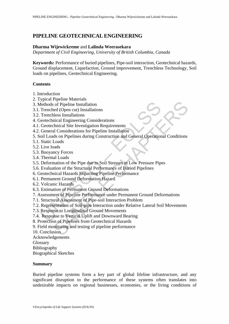
ground. This approach has been found to be very attractive since the ground provides a convenient mode of supporting the pipelines as well as protecting the pipelines from exposure to the natural elements (i.e., severe weather, UV rays) and from man-generated perils. The determination of critical loads for engineering design of buried pipes requires consideration of the internal pressure of transported fluid and/or external loads from the soil surrounding. For example, the design of high pressure lines under operating conditions is mostly governed by the internal content pressure (e.g., oil and gas pipelines) as the external soil loads are comparatively small under typical operating conditions. In comparison, for pipelines with relatively low internal pressure (e.g., water and sewer pipelines), the external soil overburden loads can be a significant design under operating conditions. Most pipelines are buried at shallow depths below the ground (less than 1.5 m) for the ease of installation and access during maintenance or repair. They need to be located at greater burial depths in situations such as below-water river crossings (see Figure 1), mountain passes, etc. Depending on the available or chosen alignment, the pipeline installation process can sometimes be economically and technically demanding. In addition to the internal pressure of the transported fluids, it is essential that buried pipelines are designed to withstand external loads that are transmitted through the surrounding soil medium (hereinafter generally referred to as “soil loads” in this document). Therefore, Geotechnical Engineering, the sub-discipline of Civil Engineering that addresses the concerns related to the use of earth as an engineering material, has a critical role to play in the design, construction, and satisfactory operation of pipelines. The soil loads imparted on pipelines can be wide ranging, and they typically include loadings that arise during the following phases encountered during the life of a given pipeline: (i) construction/installation; (ii) routine operational conditions; and (iii) extreme, less frequent, loading conditions (such as landslides, earthquake-induced ground movements, etc). Depending on the application (e.g. high or low pressures), one or a combination of the loadings associated with the above phases of loading will be of importance to the designer. This chapter presents considerations associated with pipeline geotechnical engineering specifically considering the above three phases in the life of a pipeline. Different below-ground pipeline installation methods, approaches available to quantify geotechnical loads on buried pipelines, and engineering solutions to mitigate geotechnical hazards are specifically discussed. In addition to general information such as site topography, existing underground utilities and potential for obstructions, environmental conditions, required pipeline depth, grade, tolerances, and rights-of-way requirements, suitable knowledge of subsurface soil and groundwater conditions along a given pipeline alignment and understanding of the pipe-soil interaction are the keys to design, construction, and maintenance of pipelines to meet the performance requirements.
UNESCO – EOLS
S
SAMPLE C
HAPTERS
PIPELINE ENGINEERING - Pipeline Geotechnical Engineering - Dharma Wijewickreme and Lalinda Weerasekara
©Encyclopedia of Life Support Systems (EOLSS)
Figure 1. Example of a below-water pipeline river crossing; plan and profile of design pipeline alignment– Terasen Gas Fraser River Crossing Project, Coquitlam/Surrey, B.C. 2. Typical Pipeline Materials The selection of the type of pipeline material may depend on many factors. For applications dealing with transporting high pressure fluids, the main selection criteria depend on the expected maximum internal pressure in the pipe. Since some of the buried pipelines are designed for many years of operation, pipe materials with good stress crack resistance, low permeation, high impact resistance, and satisfactory UV performance are often sought by the designers. Welded large diameter steel pipes are often used in industry applications where pipeline material strength becomes important in conveying matter such as pressurized water, oil, and natural gas. Usually, these steel pipes are coated with special coatings to protect against corrosion and abrasion and to increases the thermal efficiency. Due to the high strength and ductile nature, steel pipes are equally good in many applications involving rough terrains or regions where ground movements are expected. Polymeric plastic pipes and fittings are also used for a vast array of industrial applications such as sewer and municipal and industrial waste, gas distribution networks, potable water transportation or as subsoil field drains due to its several advantages over steel pipes. Some of the advantages of plastic pipes are: lower material cost, installation cost, maintenance cost, corrosion resistance, ease of processing, lightweight and greater extensibility. Different types of plastics are encountered in practice, e.g., PVC (Polyvinyl chloride), PE (Polyethylene), PB (Polybutylene) and PP (Polypropylene).
UNESCO – EOLS
S
SAMPLE C
HAPTERS
PIPELINE ENGINEERING - Pipeline Geotechnical Engineering - Dharma Wijewickreme and Lalinda Weerasekara
©Encyclopedia of Life Support Systems (EOLSS)
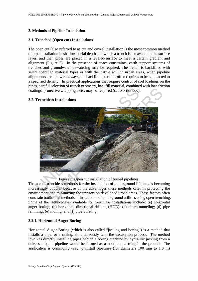
3. Methods of Pipeline Installation 3.1. Trenched (Open cut) Installations The open cut (also referred to as cut and cover) installation is the most common method of pipe installation in shallow burial depths, in which a trench is excavated in the surface layer, and then pipes are placed in a leveled-surface to meet a certain gradient and alignment (Figure 2). In the presence of space constraints, earth support systems of trenches and groundwater dewatering may be required. The trench is backfilled with select specified material types or with the native soil; in urban areas, when pipeline alignments are below roadways, the backfill material is often requires to be compacted to a specified density. In practical applications that require control of soil loadings on the pipes, careful selection of trench geometry, backfill material, combined with low-friction coatings, protective wrappings, etc. may be required (see Section 8.0). 3.2. Trenchless Installations
Figure 2. Open cut installation of buried pipelines. The use of trenchless methods for the installation of underground lifelines is becoming increasingly popular because of the advantages these methods offer in protecting the environment and minimizing the impacts on developed urban areas. These factors often constrain traditional methods of installation of underground utilities using open trenching. Some of the technologies available for trenchless installations include: (a) horizontal auger boring; (b) horizontal directional drilling (HDD); (c) micro-tunneling; (d) pipe ramming; (e) moling; and (f) pipe bursting. 3.2.1. Horizontal Auger Boring Horizontal Auger Boring (which is also called “jacking and boring”) is a method that installs a pipe, or a casing, simultaneously with the excavation process. The method involves directly installing pipes behind a boring machine by hydraulic jacking from a drive shaft; the pipeline would be formed as a continuous string in the ground. The application is commonly used to install pipelines (for diameters 100 mm to 1.8 m)
UNESCO – EOLS
S
SAMPLE C
HAPTERS
PIPELINE ENGINEERING - Pipeline Geotechnical Engineering - Dharma Wijewickreme and Lalinda Weerasekara
©Encyclopedia of Life Support Systems (EOLSS)
beneath highways, urban roads, and railway crossings without disrupting traffic. Because of the need to thrust the pipeline into the soil, only smooth walled steel or concrete pipe are typically considered for these installations. The installation of pipe into the soil is achieved via hydraulically operated jacks of adequate number and capacity to ensure smooth and uniform advancement without over-stressing of the pipe. A collar is provided to transfer the pushing pressure uniformly over the end area of the pipe. Temporary access construction shafts (“drive pits”) are typically required at suitable locations to initiate the jack and bore operations at both ends of the alignment to be crossed. It is critical for the construction shafts to be maintained at the two ends of the alignment in a drained condition with adequate and well-designed dewatering of groundwater. Operators usually work from one of the shafts, and the shafts should be located at a safe distance away from existing structures to avoid potential hazards to the structure or the public. The distance of the shaft from the roadways should be adequate with allowance made for sloping of the shaft as necessary. In the presence of space constraints, earth support systems or shaft walls may be required. Space availability for safe loading and unloading of equipment, and for spoil removal are some other considerations. The annular space between the pipe and the borehole should be typically kept filled with a bentonite/polymer slurry. While serving as a lubrication fluid to reduce the shaft friction during jacking, the slurry would also assist supporting the borehole. In sandy or unstable soil conditions, grouting of the annular space between the jacking pipe and the borehole would often be necessary. 3.2.2. Horizontal Directional Drilling As the technology develops, the application of horizontal directional drilling (HDD) for the installation of pipelines has advanced significantly in recent years. The HDD method provides a relatively cost-effective alternative to installing pipes and conduits up to about 1200 mm (48”) in diameter over distances up to 2000 m, where tight grade control is not essential. This is well demonstrated by the rapid growth in its use as a trenchless method over the last two decades. The method of HDD originated in the 1970s essentially as a fusion of technologies from the utility and oil-field industries. The installation of a pipeline utility using this technique involves the following activities: (a) drilling a pilot hole; (b) enlarging the pilot hole or pre-reaming; and (c) pullback of product pipe through the enlarged hole. The drilling is carried out using an HDD rig (see Figure 3) that is capable of drilling inclined holes while providing sufficient torque, thrust, and pullback to facilitate the above main activities. Depending on the size (generally classified as mini, midi, or maxi in the increasing sequence of rig capacity), the rigs are mounted on multiple-trailers,
UNESCO – EOLS
S
SAMPLE C
HAPTERS
PIPELINE ENGINEERING - Pipeline Geotechnical Engineering - Dharma Wijewickreme and Lalinda Weerasekara
©Encyclopedia of Life Support Systems (EOLSS)
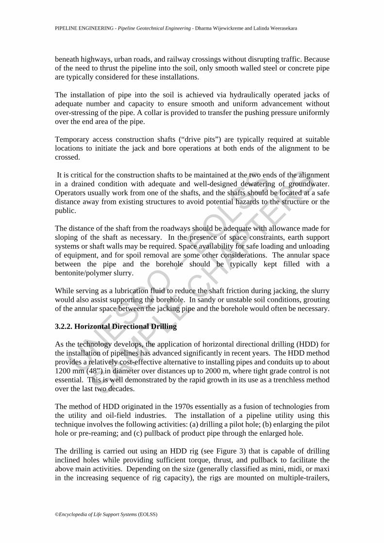
self-propelled track vehicles, or trucks.
Figure 3. Trailer-mounted HDD Maxi Rig - 500,000 lbf (2200 kN) Capacity; (a) As-mobilized rig prior to set up; and (b) Drill rod being added during operation.
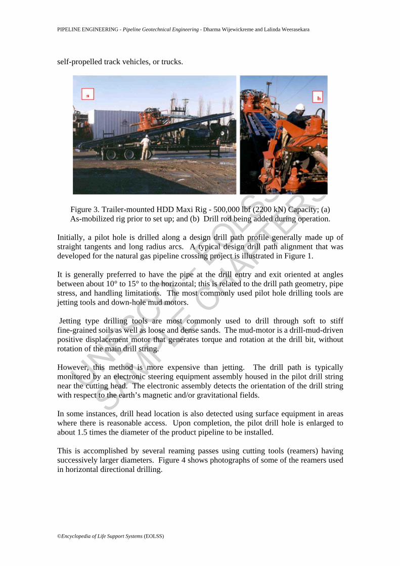
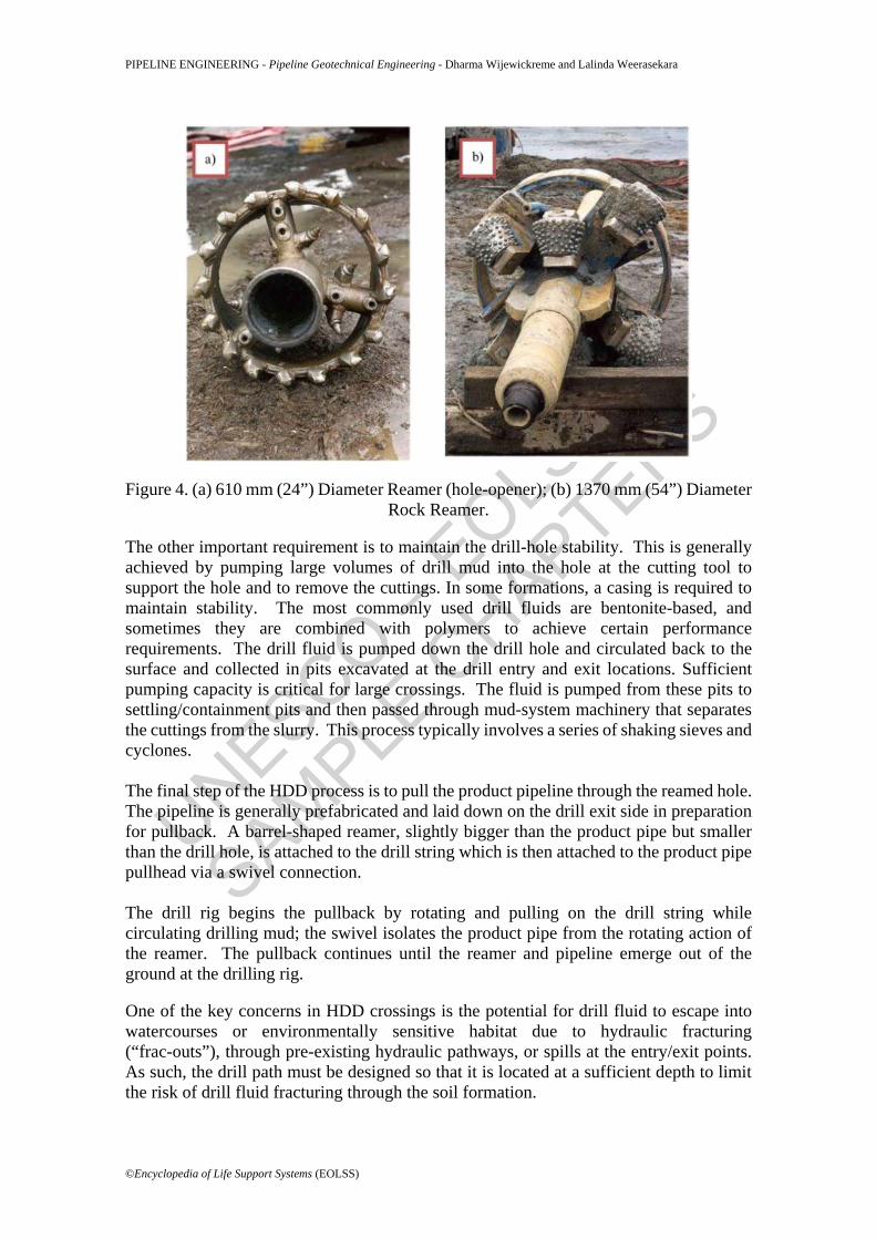
Initially, a pilot hole is drilled along a design drill path profile generally made up of straight tangents and long radius arcs. A typical design drill path alignment that was developed for the natural gas pipeline crossing project is illustrated in Figure 1. It is generally preferred to have the pipe at the drill entry and exit oriented at angles between about 10° to 15° to the horizontal; this is related to the drill path geometry, pipe stress, and handling limitations. The most commonly used pilot hole drilling tools are jetting tools and down-hole mud motors. Jetting type drilling tools are most commonly used to drill through soft to stiff fine-grained soils as well as loose and dense sands. The mud-motor is a drill-mud-driven positive displacement motor that generates torque and rotation at the drill bit, without rotation of the main drill string. However, this method is more expensive than jetting. The drill path is typically monitored by an electronic steering equipment assembly housed in the pilot drill string near the cutting head. The electronic assembly detects the orientation of the drill string with respect to the earth’s magnetic and/or gravitational fields. In some instances, drill head location is also detected using surface equipment in areas where there is reasonable access. Upon completion, the pilot drill hole is enlarged to about 1.5 times the diameter of the product pipeline to be installed. This is accomplished by several reaming passes using cutting tools (reamers) having successively larger diameters. Figure 4 shows photographs of some of the reamers used in horizontal directional drilling.
UNESCO – EOLS
S
SAMPLE C
HAPTERS
PIPELINE ENGINEERING - Pipeline Geotechnical Engineering - Dharma Wijewickreme and Lalinda Weerasekara
©Encyclopedia of Life Support Systems (EOLSS)
Figure 4. (a) 610 mm (24”) Diameter Reamer (hole-opener); (b) 1370 mm (54”) Diameter Rock Reamer.
The other important requirement is to maintain the drill-hole stability. This is generally achieved by pumping large volumes of drill mud into the hole at the cutting tool to support the hole and to remove the cuttings. In some formations, a casing is required to maintain stability. The most commonly used drill fluids are bentonite-based, and sometimes they are combined with polymers to achieve certain performance requirements. The drill fluid is pumped down the drill hole and circulated back to the surface and collected in pits excavated at the drill entry and exit locations. Sufficient pumping capacity is critical for large crossings. The fluid is pumped from these pits to settling/containment pits and then passed through mud-system machinery that separates the cuttings from the slurry. This process typically involves a series of shaking sieves and cyclones. The final step of the HDD process is to pull the product pipeline through the reamed hole. The pipeline is generally prefabricated and laid down on the drill exit side in preparation for pullback. A barrel-shaped reamer, slightly bigger than the product pipe but smaller than the drill hole, is attached to the drill string which is then attached to the product pipe pullhead via a swivel connection. The drill rig begins the pullback by rotating and pulling on the drill string while circulating drilling mud; the swivel isolates the product pipe from the rotating action of the reamer. The pullback continues until the reamer and pipeline emerge out of the ground at the drilling rig. One of the key concerns in HDD crossings is the potential for drill fluid to escape into watercourses or environmentally sensitive habitat due to hydraulic fracturing (“frac-outs”), through pre-existing hydraulic pathways, or spills at the entry/exit points. As such, the drill path must be designed so that it is located at a sufficient depth to limit the risk of drill fluid fracturing through the soil formation.
UNESCO – EOLS
S
SAMPLE C
HAPTERS
PIPELINE ENGINEERING - Pipeline Geotechnical Engineering - Dharma Wijewickreme and Lalinda Weerasekara
©Encyclopedia of Life Support Systems (EOLSS)
- - -
TO ACCESS ALL THE 44 PAGES OF THIS CHAPTER, Visit: http://www.eolss.net/Eolss-sampleAllChapter.aspx
Bibliography AASHTO. (2002). Standard Specifications for Highway Bridges (Seventeenth Edition ed.). Washington, D.C: American Associations for State Highway and Transportation Officials. [This design guidelines stipulates the standard protocols for highways and bridge designs]
ALA. (2001). Guidelines for the Design of Buried Steel Pipe. Retrieved from American Lifelines Alliance: http://www.americanlifelinesalliance.org/pdf/Update061305.pdf [This online document includes comprehensive design guidelines for various engineering aspects related to the installation and performance of buried pipelines].
ASCE. (1984). Guidelines for the seismic design of oil and gas pipeline systems. (C. o. Lifelines, Ed.) ASCE . [This document provides comprehensive design guidelines for various engineering aspects related to the installation and performance of buried pipelines].
Audibert, J., & Nyman, K. (1977). Soil restraint against horizontal motion of pipes. Journal of the Geotechnical Engineering Division (103(GT10)), 1119-1142. [The paper presents the details of the first known pullout tests performed in buried pipes. Based on these experimental results a numerical model that has been developed to represent the soil-pipe interaction in the form of lateral soil springs is also presented]
Bruschi, R., Glavina, S., Spinazze, M., Tomassini, D., Bonanni, S., & Cuscuna, S. (1996). Pipelines subjected to slow landslide movements structural modeling vs field measurement. Proceedings of the 15th International Conference on Offshore Mechanics and Arctic Engineering, June 16-20, ASME, 5, pp. 343-353. Florence, Italy. [Contains comprehensive numerical analysis of several case studies on landslide loading on pipes, and the numerical results are compared with direct field measurements]
Bughi, S., Aleotti, P., Bruschi, R., Andrei, G., Milani, G., & Scarpelli, G. (1996). Slow movements of slopes interfering with pipelines: modeling and monitoring. Proceedings of the 15th International Conference on Offshore Mechanics and Arctic Engineering, June 16-20, ASME, 5, pp. 363-372. Florence, Italy. [On the topic of pipe performance subject to landslides, this paper presents comprehensive investigation of landslides].
Burns, J., & Richard, R. (1964). Attenuation of stresses around buried cylinders. Symposium on Soil-Structure Interaction (pp. 379-392). Tucson, AZ: American Society for Testing & Materials, West Conshohocken, PA. [Presents an analytical solution to determine the stress variations around a buried cylindrical cavity]
Calvetti, F., Prisco, C., & Nova, R. (2004). Experimental and numerical analysis of soil-pipe interaction. Journal of Geotechnical and Geoenvironmental Engineering (130(2)), 1292-1299. [The pipe-soil interaction is modeled with PFC- Particle Flow Code (discrete finite element package) and with small scale laboratory tests]
Cruden, D., & Varnes, D. (1996). Landside types and processes. Landslides - Investigation and Mitigation , Special Report 247 , 36-75. (A. Turner, & S. R.L., Eds.) Transportation Research Board. [Includes detailed information on the landslides and its mitigation]
Das, B., & Seeley, G. (1975). Load displacement relationship for vertical anchor plates. Journal of Geotechnical Engineering Division (101(GT7)), 711-715. [This presents details on pullout tests performed on vertical anchor plates by the authors]
UNESCO – EOLS
S
SAMPLE C
HAPTERS
PIPELINE ENGINEERING - Pipeline Geotechnical Engineering - Dharma Wijewickreme and Lalinda Weerasekara
©Encyclopedia of Life Support Systems (EOLSS)
Dickin, E., & Leung, C. (1979). Discussion on: "Horizontally loaded vertical plate anchors in sand." Journal of Geotechnical Engineering Division (105(GT3)), 442-443. [This paper presents details on pipe pullout tests performed on a centrifuge]
Einstein, H., & Schwartz, C. (1979). Simplified analysis for tunnel supports. Journal of Geotechnical Engineering, ASCE (105 (4)), 499-518. [This contains an analytical solution to determine the interaction aspects in tunnels under overburden stress]
Guo, P., & Stolle, D. (2005). Lateral pope-soil interaction in sand with reference to scale effect. Journal of Geotechnical and Geoenvironmental Engineering (131(30), 338-349. [This presents a comprehensive analysis of the laterally loaded pipes and the discrepancies in the experimental observations are explained through numerical analysis]
Hamada, M., & O'Rourke, T. (1992). Large ground deformations and their effects on lifelines. Japanese Case Studies of Liquefaction and Lifeline Performance During Past Earthquakes. Buffalo, New York: Multidisciplinary Center for Earthquake Engineering Research. [Japanese case histories on the performance of buried pipes during earthquake induced ground deformation are presented]
Hansen, B. (1961). The ultimate resistance of rigid piles against transversal forces. Bulletin 12. Copenhagen, Denmark: Danish Geotechnical Institute. [Author presents an analytical solution for the lateral pipe resistance]
Hoeg, K. (1968). Stresses against underground structural cylinders. Journal of Soil Mechanics & Foundation Engineering (94 (4)), 833-858. [This presents an analytical solution to determine the stress variations around a cylindrical cavity subject to overburden stress]
Honegger, D., & Nyman, K. (2004). Guidelines of the Seismic Design and Assessment of Natural Gas and Liquid Hydrocarbon Pipelines. [This presents design guidelines for pipe subject to seismic loading]
Hsu, T. (1994). Rate effect on lateral soil restraint of pipeline. Soils and Foundations (33(4)), 159-169. [Paper presents results of several lateral pullout tests performed at different displacement rates and a mathematical model is derived based on the these experimental observations]
Hsu, T., Chen, Y., & Hung, W. (2006). Soil restraint to oblique movement of buried pipes in dense sand. Journal of Transportation Engineering , 132 (2), 175-181. [This presents a detailed investigation on pipes moved laterally with a finite obliquity to the axial alignment of pipeline. A pipe-soil interaction model has been developed based on the experimental results]
Hsu, T., Chen, Y., & Wy, C. (2001). Soil friction resistant of oblique pipelines in loose sand. Journal of Transportation Engineering (127(1)), 82-87. [This presents the pipe-soil interaction aspects of pipes moved laterally with a finite obliquity to the axial alignment of pipeline.]
Hutchinson, J. (1983). Methods of locating slip surfaces in landslides. Bulletin of the Association of Engineering Geologists , 20 (3), pp. 235-252. [The report discusses number of techniques for determining or estimating landslide depth]
Ishihara, K., & Yoshimine, M. (1992). Evaluation of settlements in sand deposits following liquefaction during earthquakes. Soils and Foundations , 32 (1), 173-188. [A method was presented to calculate the post-liquefaction consolidation settlements in sands]
Lee, K., & Albaisa, A. (1974). Earthquake Induced Settlements in Saturated Sands. Journal of Geotechnical Engineering (100(GT4)), 387-406. [Another method to calculate the post-liquefaction settlements in saturated sands]
Moore, I. (1987). The elastic stability of shallow buried tubes. Géotechnique , 37 (2), 151-161. [The author presents an analytical solution to determine the interaction aspects in shallow buried pipes]
Moore, I., & Brachmann, R. (1994). Three dimensional analyses of flexible circular cylinders. Journal of Geotechnical Engineering (120 (10)), 1829-1844 .[Includes finite element analysis of buried pipes under static loading]
Neely, W., Stuart, J., & Graham, J. (1973). Failure loads on vertical anchor plates in sand. Journal of the Soil Mechanics and Foundation Division (99(SM9)), 669-685. [The tests results of pullout resistance of vertical anchor plates are presented]
O'Rourke, T., Gowdy, T., Stewart, H., & Pease, J. (1991). Lifeline performance and ground deformation in
UNESCO – EOLS
S
SAMPLE C
HAPTERS
PIPELINE ENGINEERING - Pipeline Geotechnical Engineering - Dharma Wijewickreme and Lalinda Weerasekara
©Encyclopedia of Life Support Systems (EOLSS)
the marine during 1989 Loma Prieta Earthquake. Proceedings of the Third Japan-U.S. Workshop on Earthquake Resistant Design of Lifeline Facilities and Countermeasures for Soil Liquefaction. NCEER-91-001, pp. 129-146. San Francisco, California: Multidisciplinary Center for Earthquake Engineering Research, Buffalo, New York. [The performance of lifelines during Loma Prieta earthquake is presented]
Ovesen, N. (1964). Anchor slabs, calculation method and model tests. Bulletin 16 . Copenhagen: Danish Geotechnical Institute. [This includes an analytical solution to calculate the lateral soil resistance of a pipe]
Paulin, M., Phillips, R., Clark, J., Hurley, S., & Trigg, A. (1997). Establishment of a full-scale pipeline/soil interaction test facility and results from lateral and axial investigations in sand. 16th International Conference of Offshore Mechanics and Arctic Engineering, OMAE, 5, pp. 139-146. [This presents experimental results of series of pipe pullout tests performed at C-CORE]
Popescu, R., Phillips, R., Konuk, I., Guo, P., & Nonahar, A. (2002). Pipe-soil Interaction: Large scale tests and numerical modeling. International Conference on Physical Modeling in Geotechnics. St. John's, NF, Canada. [The paper presents the numerical modeling of the large scale pipe pullout tests performed at C-CORE]
Rowe, R., & Davis, E. (1982). The behaviour of anchor plates in sand. Geotechnique (32(1)), 25-41. [The paper discusses a numerical model to capture the pullout resistance of vertical anchor plates]
Spangler, M. (1956). Stresses in pressure pipe-lines and protective casting pipes. Journal of Structural Engineering (82), 1-33. (The paper presents an analytical solution to determine the performance of a flexible pipe subject to overburden stress)
Tokimatsu, K., & Seed, B. (1987). Evaluation of settlements due to earthquake shaking. Journal of Geotechnical Engineering 113 (8), 861-878. [Proposed a method to find the post-earthquake settlements in sands]
Trautmann, C. H., & O'Rourke, T. D. (1983). Behaviour of Pipe in dry sand under lateral and uplift loading. Geotechnical Engineering Report, Cornell University, Ithaca, N.Y. [Conducted lateral pullout and uplift tests on pipes at Cornell University]
Trautmann, C., & O'Rourke, T. (1985). Lateral force displacement response of buried pipe. Journal of Geotechnical Engineering (111(9)), 1077-1092.[Paper containing details of experimental results of lateral pipe pullout tests and soil springs derived from these experimental results]
Weerasekara, L., & Wijewickreme, D. (2008). Mobilization of soil loads on buried, polyethylene natural gas pipelines subject to relative axial displacements. Canadian Geotechnical Journal, 45 (9), 1237-1249. [Presents an analytical solution to capture the pipe response of an extensible pipe]
Wijewickreme, D., Karimian, H., & Honegger, D. (2009). Response of buried steel pipelines subjected to relative axial soil movement. Canadian Geotechnical Journal, 46 (7), 735-752. [This presents test results of axial pipe pullout test performed on steel pipes in a large scale soil chamber]
Wijewickreme, D., & Sanin, M. (2009). Post-cyclic reconsolidation strains in low plastic fine-grained silts due to dissipation of excess pore water pressures. Journal of Geotechnical and Geoenvironmental Engineering, ASCE (Manuscript No. GTENG-1063). [Discusses the post-liquefaction settlements in fine grained silts derived from direct simple shear testing]
Wijewickreme, D., Karimian, H., & Honegger, D. (2005). Effectiveness of some methods for reducing axial soil loads on buried pipelines subjected to ground movements. 58th Canadian Geotechnical Conference. Saskatoon. [Presents experimental evidence of reducing the axial frictional soil load during relative axial ground movements by wrapping pipes with geotextiles]
Yasuhara, K., Murakami, S., Toyota, N., & Hyde, A. (2001). Settlements in fine-grained solids under cyclic loading. Soils and Foundations , 41 (6), 25-36. [Presents details on settlement of fine grained soils subject to cyclic loading]
Youd, T., & Perkins, D. (1987). Mapping of Liquefaction Severity Index. Journal of Geotechnical Engineering, ASCE , 113 (11), 1374-1392. [Provides a general method for mapping the liquefaction susceptibility based on the geological characteristics of a given area]
Zhang, G., Robertson, P., & Brachman, R. (2002). Estimating Liquefaction-induced Ground Settlements
UNESCO – EOLS
S
SAMPLE C
HAPTERS
PIPELINE ENGINEERING - Pipeline Geotechnical Engineering - Dharma Wijewickreme and Lalinda Weerasekara
©Encyclopedia of Life Support Systems (EOLSS)
from CPT for Level Ground. Canadian Geotechnical Journal (39), 1168-1180. [Presents an empirical method to estimate the liquefaction induced ground settlements from CPT results]
Biographical Sketches Dharma Wijewickreme, Ph.D., P.Eng. obtained his doctorate degree from the University of British Columbia (UBC), Vancouver, BC, Canada, in 1990. After gaining some 11 years of industry consulting experience in Geotechnical Engineering, primarily in the area of seismic vulnerability assessment of lifelines, he joined the Department of Civil Engineering of UBC in January 2001 where he currently serves as an Associate Professor of Civil Engineering. His key research areas at UBC include soil-pipeline interaction (physical model testing) emphasizing on the performance of pipelines, subject to permanent ground displacements and characterization of the mechanical response of geo-materials under static and cyclic loading conditions (laboratory element testing). In collaboration with the UBC Mining Engineering Department, Dr. Wijewickreme is also contributing to sustainable mine waste management practices through experimental research on the mechanical behavior of co-disposed mine waste. His research vision has been recognized key local and international industry partners and several inter-university collaborations. His work has led to establishing a pipe-soil interaction research facility (with a 2.5 x 4.0 x 3.0 m full-scale soil testing chamber) and upgrading the geotechnical laboratory element testing research facility at UBC. Dr. Wijewickreme has memberships in a number of leading professional societies of Civil Engineering and is presently serving as an Editorial Board Member of the Geotechnical Testing Journal of the American Society for Testing and Materials (ASTM) and is acting as an Associate Editor of the Canadian Geotechnical Journal. He is extensively involved in the activities of the Canadian Geotechnical Society (CGS), and is currently the Chair of the National Education Committee. He is also a Member of the Geotechnical Research Board of the CGS. Lalinda Weerasekara is a Ph.D candidate working in the field of pipeline geotechnical engineering at University of British Columbia (UBC), Canada. His research focuses on the performance of buried polyethylene natural gas pipelines subject to ground movements. He obtained his (M.A.Sc) degree in Civil Engineering at UBC in 2007. After completing his B.Sc (Eng) in 2002 at University of Peradeniya, Sri Lanka, he served as an Assistant Lecturer for about one and a half years at the same university, before he joined Aqua Technologies (Pvt) Ltd, as a Civil Engineer for about a year.