pipeline slings catalog - bishop lifting products · 2019-10-15 · pipeline slings (800)...
TRANSCRIPT
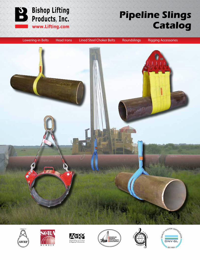
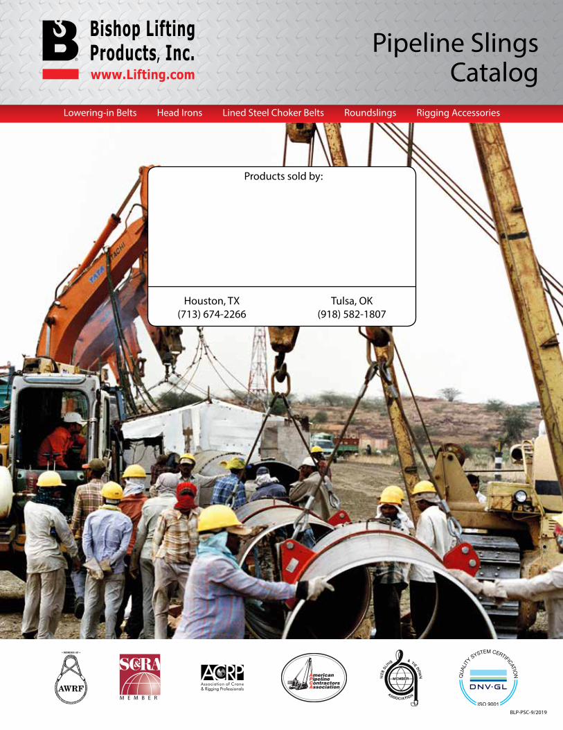
Pipeline SlingsCatalog
Lowering-in Belts Head Irons Lined Steel Choker Belts Roundslings Rigging Accessories
M E M B E R
Pipeline Slings
(800) 972-1041 (800) 972-1041Pipeline Slings
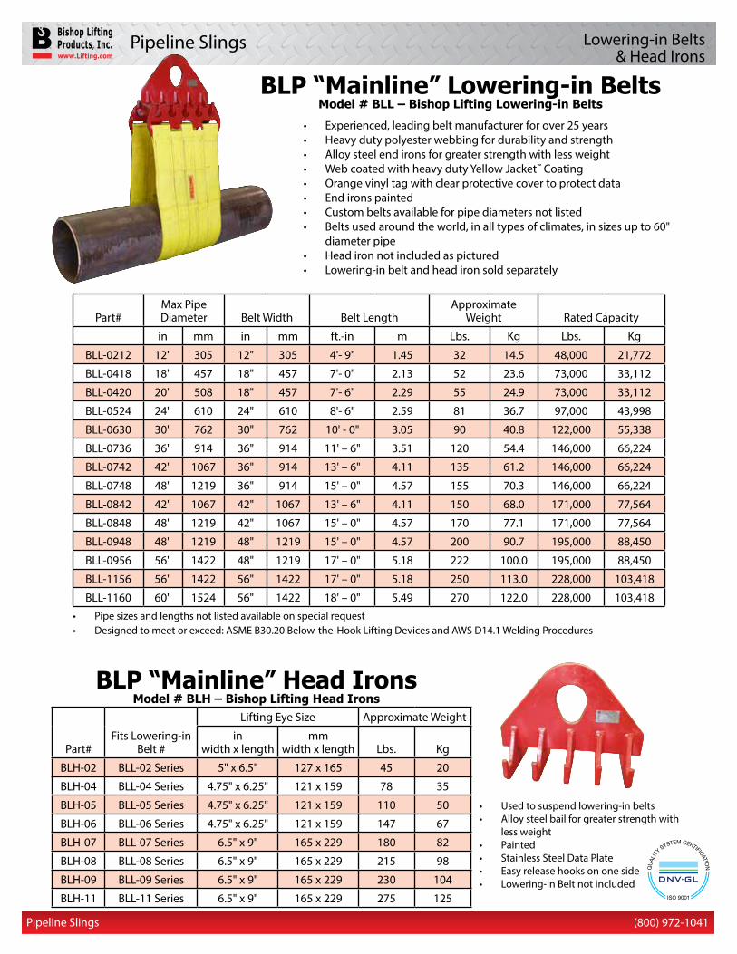
• Pipe sizes and lengths not listed available on special request• Designed to meet or exceed: ASME B30.20 Below-the-Hook Lifting Devices and AWS D14.1 Welding Procedures
Part#Max Pipe Diameter Belt Width Belt Length
ApproximateWeight Rated Capacity
in mm in mm ft.-in m Lbs. Kg Lbs. Kg
BLL-0212 12" 305 12" 305 4'- 9" 1.45 32 14.5 48,000 21,772
BLL-0418 18" 457 18" 457 7'- 0" 2.13 52 23.6 73,000 33,112
BLL-0420 20" 508 18" 457 7'- 6" 2.29 55 24.9 73,000 33,112
BLL-0524 24" 610 24" 610 8'- 6" 2.59 81 36.7 97,000 43,998
BLL-0630 30" 762 30" 762 10' - 0" 3.05 90 40.8 122,000 55,338
BLL-0736 36" 914 36" 914 11' – 6" 3.51 120 54.4 146,000 66,224
BLL-0742 42" 1067 36" 914 13' – 6" 4.11 135 61.2 146,000 66,224
BLL-0748 48" 1219 36" 914 15' – 0" 4.57 155 70.3 146,000 66,224
BLL-0842 42" 1067 42" 1067 13' – 6" 4.11 150 68.0 171,000 77,564
BLL-0848 48" 1219 42" 1067 15' – 0" 4.57 170 77.1 171,000 77,564
BLL-0948 48" 1219 48" 1219 15' – 0" 4.57 200 90.7 195,000 88,450
BLL-0956 56" 1422 48" 1219 17' – 0" 5.18 222 100.0 195,000 88,450
BLL-1156 56" 1422 56" 1422 17' – 0" 5.18 250 113.0 228,000 103,418
BLL-1160 60" 1524 56" 1422 18' – 0" 5.49 270 122.0 228,000 103,418
• Experienced, leading belt manufacturer for over 25 years• Heavy duty polyester webbing for durability and strength• Alloy steel end irons for greater strength with less weight• Web coated with heavy duty Yellow Jacket™ Coating• Orange vinyl tag with clear protective cover to protect data • End irons painted• Custom belts available for pipe diameters not listed• Belts used around the world, in all types of climates, in sizes up to 60"
diameter pipe• Head iron not included as pictured• Lowering-in belt and head iron sold separately
BLP “Mainline” Lowering-in BeltsModel # BLL – Bishop Lifting Lowering-in Belts
Lowering-in Belts& Head Irons
• Used to suspend lowering-in belts• Alloy steel bail for greater strength with
less weight• Painted • Stainless Steel Data Plate• Easy release hooks on one side • Lowering-in Belt not included
BLP “Mainline” Head IronsModel # BLH – Bishop Lifting Head Irons
Part#Fits Lowering-in
Belt #
Lifting Eye Size Approximate Weight
inwidth x length
mmwidth x length Lbs. Kg
BLH-02 BLL-02 Series 5" x 6.5" 127 x 165 45 20
BLH-04 BLL-04 Series 4.75" x 6.25" 121 x 159 78 35
BLH-05 BLL-05 Series 4.75" x 6.25" 121 x 159 110 50
BLH-06 BLL-06 Series 4.75" x 6.25" 121 x 159 147 67
BLH-07 BLL-07 Series 6.5" x 9" 165 x 229 180 82
BLH-08 BLL-08 Series 6.5" x 9" 165 x 229 215 98
BLH-09 BLL-09 Series 6.5" x 9" 165 x 229 230 104
BLH-11 BLL-11 Series 6.5" x 9" 165 x 229 275 125
Pipeline Slings
(800) 972-1041 (800) 972-1041Pipeline Slings 2
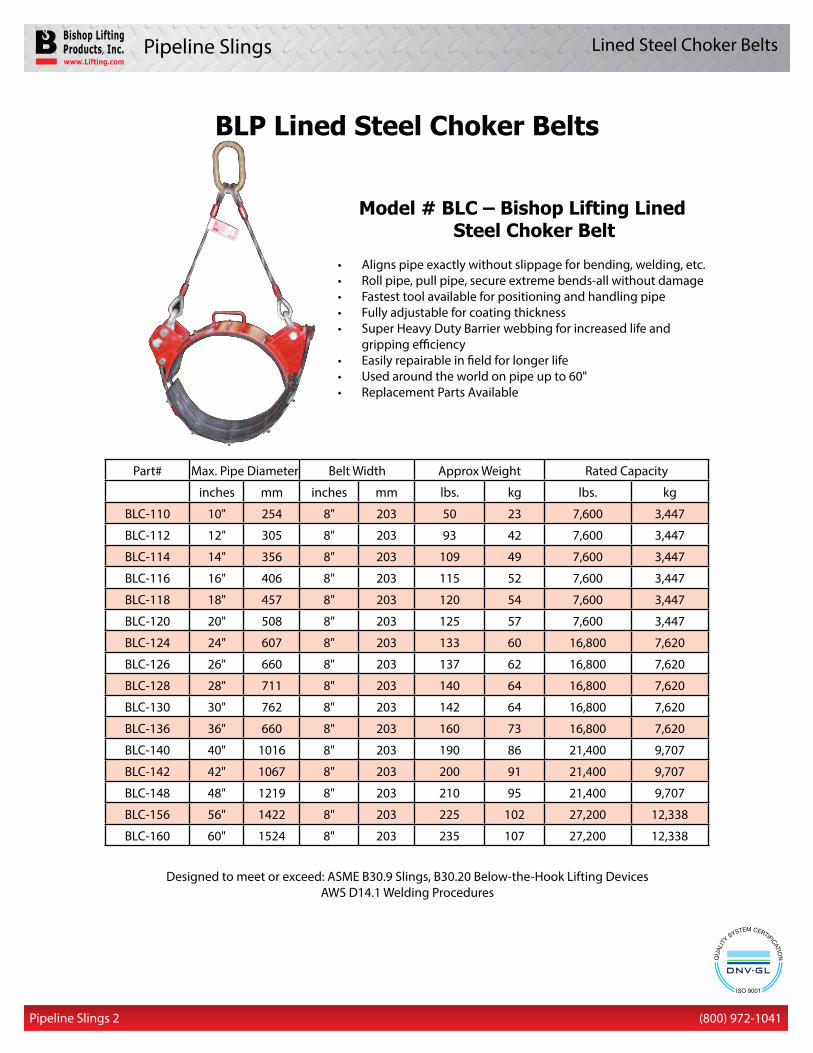
Designed to meet or exceed: ASME B30.9 Slings, B30.20 Below-the-Hook Lifting DevicesAWS D14.1 Welding Procedures
Model # BLC – Bishop Lifting Lined Steel Choker Belt
• Aligns pipe exactly without slippage for bending, welding, etc.• Roll pipe, pull pipe, secure extreme bends-all without damage• Fastest tool available for positioning and handling pipe• Fully adjustable for coating thickness• Super Heavy Duty Barrier webbing for increased life and
gripping efficiency• Easily repairable in field for longer life• Used around the world on pipe up to 60"• Replacement Parts Available
Part# Max. Pipe Diameter Belt Width Approx Weight Rated Capacity
inches mm inches mm lbs. kg lbs. kg
BLC-110 10" 254 8" 203 50 23 7,600 3,447
BLC-112 12" 305 8" 203 93 42 7,600 3,447
BLC-114 14" 356 8" 203 109 49 7,600 3,447
BLC-116 16" 406 8" 203 115 52 7,600 3,447
BLC-118 18" 457 8" 203 120 54 7,600 3,447
BLC-120 20" 508 8" 203 125 57 7,600 3,447
BLC-124 24" 607 8" 203 133 60 16,800 7,620
BLC-126 26" 660 8" 203 137 62 16,800 7,620
BLC-128 28" 711 8" 203 140 64 16,800 7,620
BLC-130 30" 762 8" 203 142 64 16,800 7,620
BLC-136 36" 660 8" 203 160 73 16,800 7,620
BLC-140 40" 1016 8" 203 190 86 21,400 9,707
BLC-142 42" 1067 8" 203 200 91 21,400 9,707
BLC-148 48" 1219 8" 203 210 95 21,400 9,707
BLC-156 56" 1422 8" 203 225 102 27,200 12,338
BLC-160 60" 1524 8" 203 235 107 27,200 12,338
BLP Lined Steel Choker Belts
Lined Steel Choker Belts
Pipeline Slings
(800) 972-1041(800) 972-1041 Pipeline Slings 3
Approx. IWRC Diameter wt./ft. Minimum breaking force (in.) (lbs.) (tons of 2,000 lbs.) XIP® XXIP®
1/4 0.116 3.40 5/16 0.18 5.27
3/8 0.26 7.55 8.30 7/16 0.35 10.2 11.2 1/2 0.46 13.3 14.6
9/16 0.59 16.8 18.5 5/8 0.7 20.6 22.7 3/4 1.0 29.4 32.4
7/8 1.42 39.8 43.8 1 1.85 51.7 56.9 1 1/8 2.34 65.0 71.5
1 1/4 2.89 79.9 87.9 1 3/8 3.50 96.0 106 1 1/2 4.16 114 125
1 5/8 4.88 132 146 1 3/4 5.67 153 169 1 7/8 6.50 174 192
2 7.39 198 217 2 1/8 8.35 221 244 2 1/4 9.36 247 272
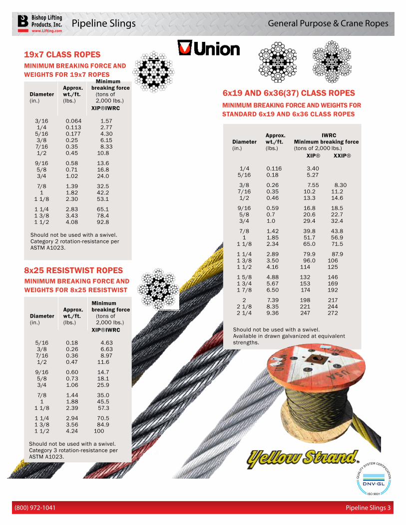
Should not be used with a swivel. Available in drawn galvanized at equivalent strengths.
6x19 AND 6x36(37) CLASS ROPES
19x7 CLASS ROPES
8x25 RESISTWIST ROPES
MINIMUM BREAKING FORCE AND WEIGHTS FOR STANDARD 6x19 AND 6x36 CLASS ROPES
MINIMUM BREAKING FORCE AND WEIGHTS FOR 8x25 RESISTWIST
Minimum Approx. breaking force Diameter wt./ft. (tons of (in.) (lbs.) 2,000 lbs.) XIP® IWRC
5/16 0.18 4.63 3/8 0.26 6.63 7/16 0.36 8.97 1/2 0.47 11.6
9/16 0.60 14.7 5/8 0.73 18.1 3/4 1.06 25.9
7/8 1.44 35.0 1 1.88 45.5 1 1/8 2.39 57.3
1 1/4 2.94 70.5 1 3/8 3.56 84.9 1 1/2 4.24 100
Should not be used with a swivel. Category 3 rotation-resistance per ASTM A1023.
MINIMUM BREAKING FORCE AND WEIGHTS FOR 19x7 ROPES Minimum Approx. breaking force Diameter wt./ft. (tons of (in.) (lbs.) 2,000 lbs.) XIP® IWRC
3/16 0.064 1.57 1/4 0.113 2.77 5/16 0.177 4.30 3/8 0.25 6.15 7/16 0.35 8.33 1/2 0.45 10.8
9/16 0.58 13.6 5/8 0.71 16.8 3/4 1.02 24.0
7/8 1.39 32.5 1 1.82 42.2 1 1/8 2.30 53.1
1 1/4 2.83 65.1 1 3/8 3.43 78.4 1 1/2 4.08 92.8
Should not be used with a swivel. Category 2 rotation-resistance per ASTM A1023.
General Purpose & Crane Ropes
Pipeline Slings
(800) 972-1041 (800) 972-1041
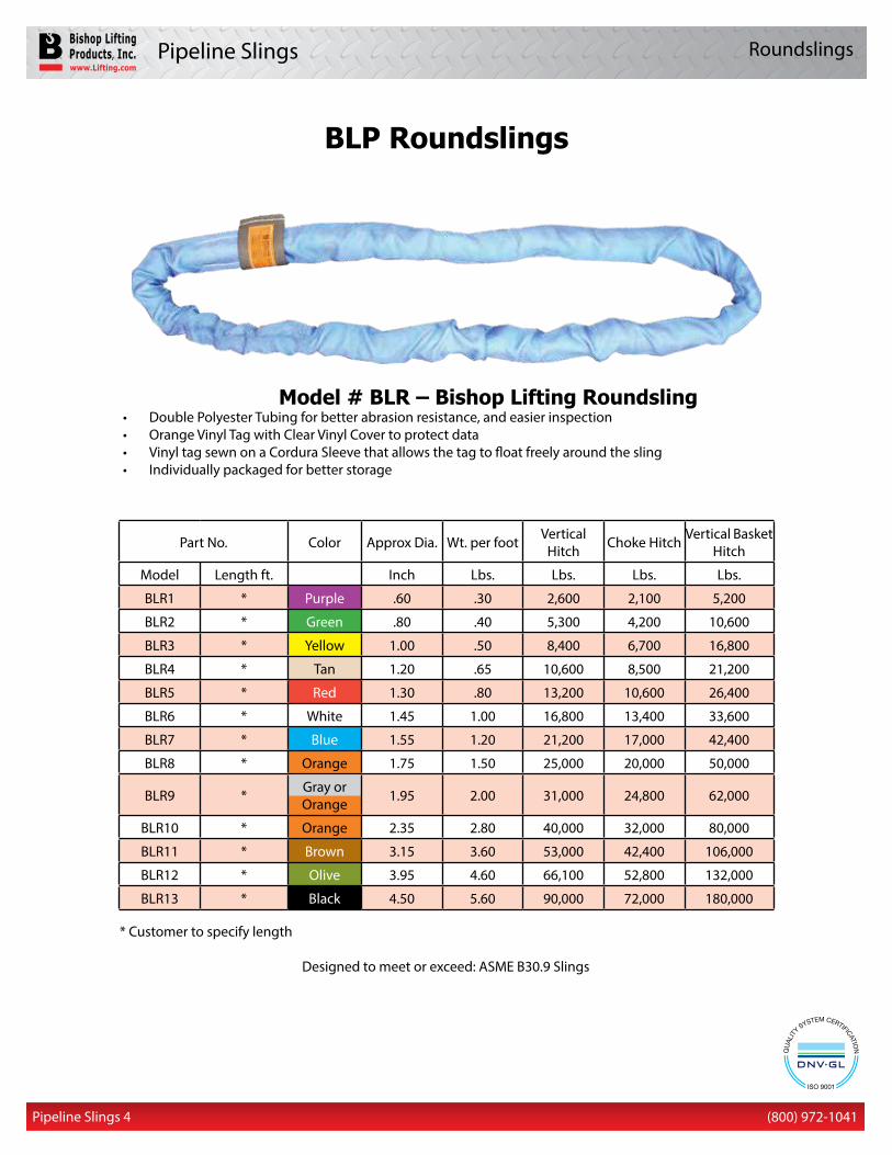
Part No. Color Approx Dia. Wt. per foot VerticalHitch Choke Hitch Vertical Basket
Hitch
Model Length ft. Inch Lbs. Lbs. Lbs. Lbs.
BLR1 * Purple .60 .30 2,600 2,100 5,200
BLR2 * Green .80 .40 5,300 4,200 10,600
BLR3 * Yellow 1.00 .50 8,400 6,700 16,800
BLR4 * Tan 1.20 .65 10,600 8,500 21,200
BLR5 * Red 1.30 .80 13,200 10,600 26,400
BLR6 * White 1.45 1.00 16,800 13,400 33,600
BLR7 * Blue 1.55 1.20 21,200 17,000 42,400
BLR8 * Orange 1.75 1.50 25,000 20,000 50,000
BLR9 * Gray or Orange 1.95 2.00 31,000 24,800 62,000
BLR10 * Orange 2.35 2.80 40,000 32,000 80,000
BLR11 * Brown 3.15 3.60 53,000 42,400 106,000
BLR12 * Olive 3.95 4.60 66,100 52,800 132,000
BLR13 * Black 4.50 5.60 90,000 72,000 180,000
Model # BLR – Bishop Lifting Roundsling• Double Polyester Tubing for better abrasion resistance, and easier inspection• Orange Vinyl Tag with Clear Vinyl Cover to protect data• Vinyl tag sewn on a Cordura Sleeve that allows the tag to float freely around the sling• Individually packaged for better storage
* Customer to specify length
Designed to meet or exceed: ASME B30.9 Slings
BLP Roundslings
Pipeline Slings 4
Roundslings
Pipeline Slings
(800) 972-1041(800) 972-1041
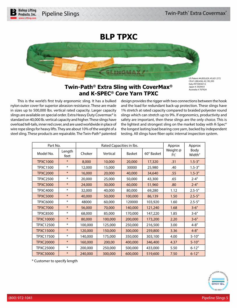
BLP TPXC
Part No. Rated Capacities in lbs. Approx Weight @
Ft.'
Approx Body
Width"Model No. Lengthfeet Choker Vertical Basket 60° Basket
TPXC1000 * 8,000 10,000 20,000 17,320 .31 1.5-3"TPXC1500 * 12,000 15,000 30000 25,980 .40 1.5-3"TPXC2000 * 16,000 20,000 40,000 34,640 .55 1.5-3"TPXC2500 * 20,000 25,000 50,000 43,300 .65 2-4"TPXC3000 * 24,000 30,000 60,000 51,960 .80 2-4"TPXC4000 * 32,000 40,000 80,000 69,280 1.12 2.5-5"TPXC5000 * 40,000 50,000 100,000 86,139 1.50 2.5-5"TPXC6000 * 48000 60,000 120000 103,920 1.60 2.5-5"TPXC7000 * 56,000 70,000 140,000 121,240 1.68 3-6"TPXC8500 * 68,000 85,000 170,000 147,220 1.85 3-6"
TPXC10000 * 80,000 100,000 200,000 173,200 2.20 3-6"TPXC12500 * 100,000 125,000 250,000 216,500 3.00 4-8"TPXC15000 * 120,000 150,000 300,000 259,800 3.36 4-8"TPXC17500 * 140,000 175,000 350,000 303,100 4.00 5-10"TPXC20000 * 160,000 200,00 400,000 346,400 4.37 5-10"TPXC25000 * 200,000 250,000 500,000 433,000 5.50 6-12"TPXC30000 * 240,000 300,000 600,000 519,600 7.50 6-12"
Twin-Path® Extra Sling with CoverMax® and K-SPEC® Core Yarn TPXC
* Customer to specify length
US Patent #4,850,629, #5,651,572 CN #1,280,458, #2,195,393 Italy #97300367.6 Japan # 2929431 Australia # 707924
This is the world’s first truly ergonomic sling. It has a bulked nylon outer cover for superior abrasion resistance. These are made in sizes up to 500,000 lbs. vertical rated capacity. Larger capacity slings are available on special order. Extra Heavy Duty Covermax® is standard on 40,000 lb. vertical capacity and higher. These slings have overload tell-tails, inner red cover, and are used worldwide in place of wire rope slings for heavy lifts. They are about 10% of the weight of a steel sling. These products are repairable. The Twin-Path® patented
design provides the rigger with two connections between the hook and the load for redundant back-up protection. These slings have 1% stretch at rated capacity compared to braided polyester round slings which can stretch up to 9%. If ergonomics, productivity and safety are important, then these slings are the only choice. This is the lightest and strongest sling on the market today with K-Spec® the longest lasting load bearing core yarn, backed by independent testing. All slings have fiber optic internal inspection system.
Pipeline Slings 5
Twin-Path® Extra Covermax®
Pipeline Slings
(800) 972-1041 (800) 972-1041
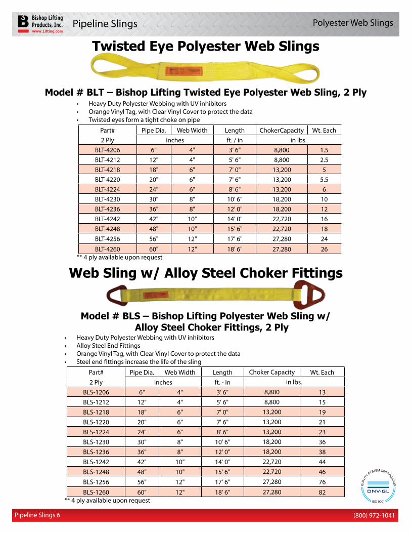
Twisted Eye Polyester Web Slings
• Heavy Duty Polyester Webbing with UV inhibitors • Orange Vinyl Tag, with Clear Vinyl Cover to protect the data• Twisted eyes form a tight choke on pipe
Part# Pipe Dia. Web Width Length Choker Capacity Wt. Each2 Ply inches ft. / in in lbs.
BLT-4206 6" 4" 3' 6" 8,800 1.5BLT-4212 12" 4" 5' 6" 8,800 2.5BLT-4218 18" 6" 7' 0" 13,200 5BLT-4220 20" 6" 7' 6" 13,200 5.5BLT-4224 24" 6" 8' 6" 13,200 6BLT-4230 30" 8" 10' 6" 18,200 10BLT-4236 36" 8" 12' 0" 18,200 12BLT-4242 42" 10" 14' 0" 22,720 16BLT-4248 48" 10" 15' 6" 22,720 18BLT-4256 56" 12" 17' 6" 27,280 24
BLT-4260 60" 12" 18' 6" 27,280 26** 4 ply available upon request
Model # BLT – Bishop Lifting Twisted Eye Polyester Web Sling, 2 Ply
Pipeline Slings 6
Polyester Web Slings
Web Sling w/ Alloy Steel Choker Fittings
• Heavy Duty Polyester Webbing with UV inhibitors• Alloy Steel End Fittings• Orange Vinyl Tag, with Clear Vinyl Cover to protect the data• Steel end fittings increase the life of the sling
Part# Pipe Dia. Web Width Length Choker Capacity Wt. Each2 Ply inches ft. - in in lbs.
BLS-1206 6" 4" 3' 6" 8,800 13 BLS-1212 12" 4" 5' 6" 8,800 15 BLS-1218 18" 6" 7' 0" 13,200 19 BLS-1220 20" 6" 7' 6" 13,200 21 BLS-1224 24" 6" 8' 6" 13,200 23 BLS-1230 30" 8" 10' 6" 18,200 36 BLS-1236 36" 8" 12' 0" 18,200 38 BLS-1242 42" 10" 14' 0" 22,720 44BLS-1248 48" 10" 15' 6" 22,720 46
BLS-1256 56" 12" 17' 6" 27,280 76
BLS-1260 60" 12" 18' 6" 27,280 82** 4 ply available upon request
Model # BLS – Bishop Lifting Polyester Web Sling w/ Alloy Steel Choker Fittings, 2 Ply
Pipeline Slings
(800) 972-1041(800) 972-1041
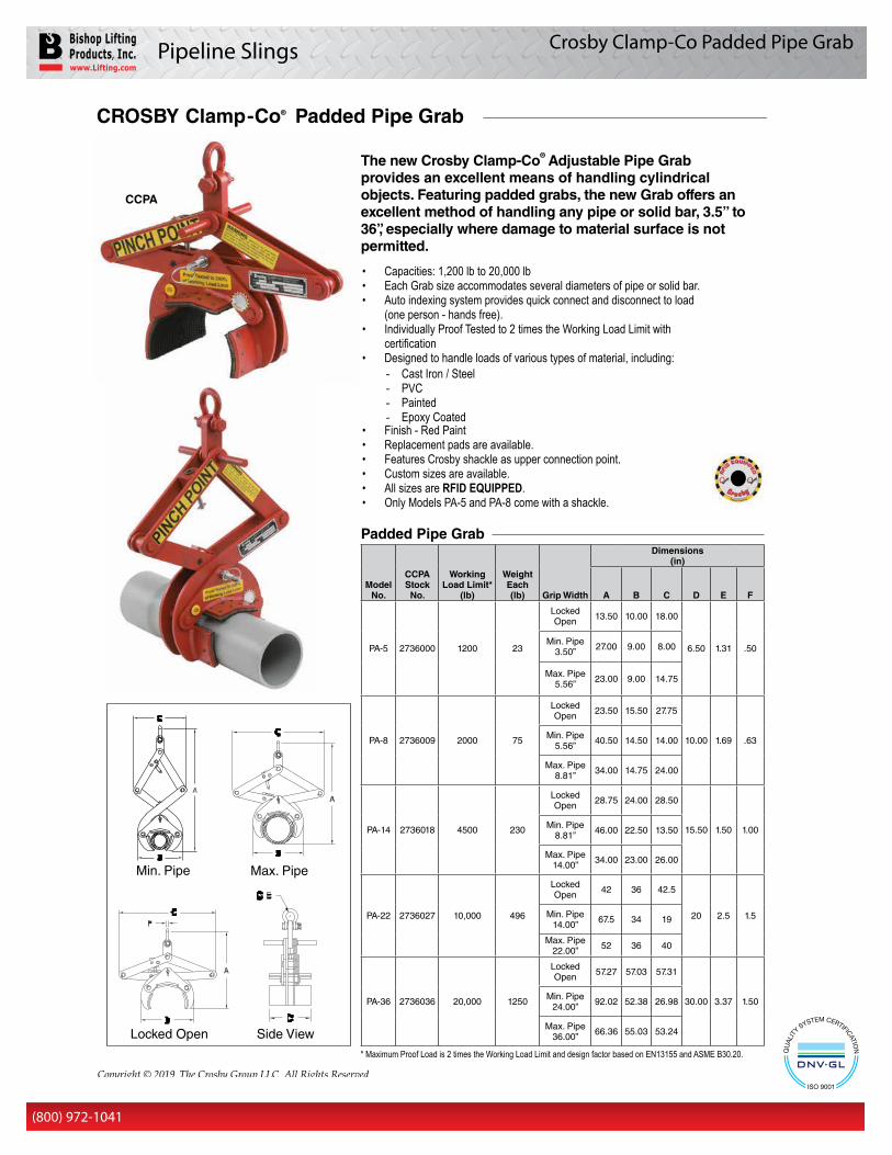
Crosby Clamp-Co Padded Pipe Grab
431Copyright © 2019 The Crosby Group LLC All Rights Reserved
Cro
sby
Lift
ing
C
lam
ps
The new Crosby Clamp-Co® Adjustable Pipe Grab provides an excellent means of handling cylindrical objects. Featuring padded grabs, the new Grab offers an excellent method of handling any pipe or solid bar, 3.5” to 36”, especially where damage to material surface is not permitted.
• Capacities: 1,200 lb to 20,000 lb• Each Grab size accommodates several diameters of pipe or solid bar.• Auto indexing system provides quick connect and disconnect to load
(one person - hands free).• Individually Proof Tested to 2 times the Working Load Limit with
certification• Designed to handle loads of various types of material, including:
- Cast Iron / Steel - PVC - Painted - Epoxy Coated
• Finish - Red Paint• Replacement pads are available.• Features Crosby shackle as upper connection point.• Custom sizes are available.• All sizes are RFID EQUIPPED.• Only Models PA-5 and PA-8 come with a shackle.
* Maximum Proof Load is 2 times the Working Load Limit and design factor based on EN13155 and ASME B30.20.
CCPA
Padded Pipe Grab
Model No.
CCPAStock No.
Working Load Limit*
(lb)
Weight Each (lb) Grip Width
Dimensions (in)
A B C D E F
PA-5 2736000 1200 23
Locked Open 13.50 10.00 18.00
6.50 1.31 .50Min. Pipe
3.50” 27.00 9.00 8.00
Max. Pipe 5.56” 23.00 9.00 14.75
PA-8 2736009 2000 75
Locked Open 23.50 15.50 27.75
10.00 1.69 .63Min. Pipe 5.56” 40.50 14.50 14.00
Max. Pipe 8.81” 34.00 14.75 24.00
PA-14 2736018 4500 230
Locked Open 28.75 24.00 28.50
15.50 1.50 1.00Min. Pipe 8.81” 46.00 22.50 13.50
Max. Pipe 14.00” 34.00 23.00 26.00
PA-22 2736027 10,000 496
Locked Open 42 36 42.5
20 2.5 1.5Min. Pipe14.00” 67.5 34 19
Max. Pipe 22.00” 52 36 40
PA-36 2736036 20,000 1250
LockedOpen 57.27 57.03 57.31
30.00 3.37 1.50Min. Pipe24.00” 92.02 52.38 26.98
Max. Pipe36.00” 66.36 55.03 53.24Locked Open
Min. Pipe Max. Pipe
Side View
CROSBY Clamp -Co® Padded Pipe Grab
Clamp-Co AdjustablePadded PipeGrab
Pipeline Slings
(800) 972-1041(800) 972-1041 Pipeline Slings 7
Crosby Clamp-Co Pipe Grabs
432
CR
OS
BY
® L
IFT
ING
CL
AM
PS
Copyright © 2019 The Crosby Group LLC All Rights Reserved
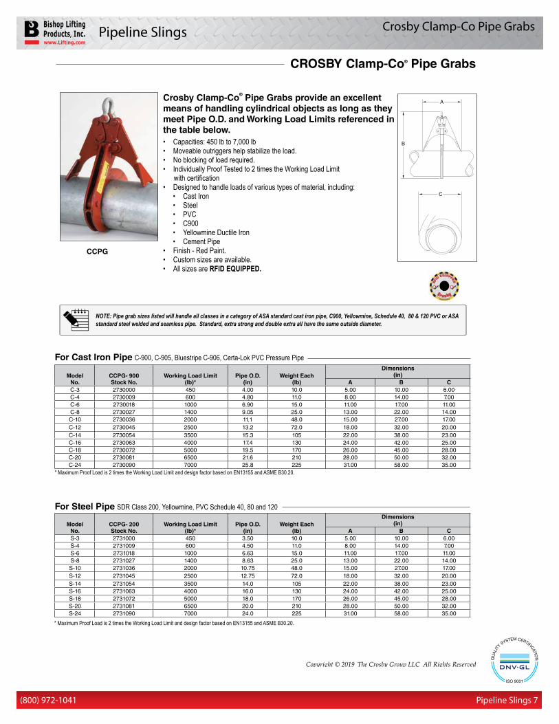
Crosby Clamp-Co® Pipe Grabs provide an excellent means of handling cylindrical objects as long as they meet Pipe O.D. and Working Load Limits referenced in the table below.• Capacities: 450 lb to 7,000 lb• Moveable outriggers help stabilize the load.• No blocking of load required.• Individually Proof Tested to 2 times the Working Load Limit with certification• Designed to handle loads of various types of material, including:
• Cast Iron• Steel• PVC• C900• Yellowmine Ductile Iron• Cement Pipe
• Finish - Red Paint.• Custom sizes are available.• All sizes are RFID EQUIPPED.
CCPG
For Steel Pipe SDR Class 200, Yellowmine, PVC Schedule 40, 80 and 120
ModelNo.
CCPG- 900Stock No.
Working Load Limit(lb)*
Pipe O.D.(in)
Weight Each(lb)
Dimensions(in)
A B CC-3 2730000 450 4.00 10.0 5.00 10.00 6.00C-4 2730009 600 4.80 11.0 8.00 14.00 7.00C-6 2730018 1000 6.90 15.0 11.00 17.00 11.00C-8 2730027 1400 9.05 25.0 13.00 22.00 14.00C-10 2730036 2000 11.1 48.0 15.00 27.00 17.00C-12 2730045 2500 13.2 72.0 18.00 32.00 20.00C-14 2730054 3500 15.3 105 22.00 38.00 23.00C-16 2730063 4000 17.4 130 24.00 42.00 25.00C-18 2730072 5000 19.5 170 26.00 45.00 28.00C-20 2730081 6500 21.6 210 28.00 50.00 32.00C-24 2730090 7000 25.8 225 31.00 58.00 35.00
ModelNo.
CCPG- 200Stock No.
Working Load Limit(lb)*
Pipe O.D.(in)
Weight Each(lb)
Dimensions(in)
A B CS-3 2731000 450 3.50 10.0 5.00 10.00 6.00S-4 2731009 600 4.50 11.0 8.00 14.00 7.00S-6 2731018 1000 6.63 15.0 11.00 17.00 11.00S-8 2731027 1400 8.63 25.0 13.00 22.00 14.00S-10 2731036 2000 10.75 48.0 15.00 27.00 17.00S-12 2731045 2500 12.75 72.0 18.00 32.00 20.00S-14 2731054 3500 14.0 105 22.00 38.00 23.00S-16 2731063 4000 16.0 130 24.00 42.00 25.00S-18 2731072 5000 18.0 170 26.00 45.00 28.00S-20 2731081 6500 20.0 210 28.00 50.00 32.00S-24 2731090 7000 24.0 225 31.00 58.00 35.00
For Cast Iron Pipe C-900, C-905, Bluestripe C-906, Certa-Lok PVC Pressure Pipe
* Maximum Proof Load is 2 times the Working Load Limit and design factor based on EN13155 and ASME B30.20.
* Maximum Proof Load is 2 times the Working Load Limit and design factor based on EN13155 and ASME B30.20.
NOTE: Pipe grab sizes listed will handle all classes in a category of ASA standard cast iron pipe, C900, Yellowmine, Schedule 40, 80 & 120 PVC or ASA standard steel welded and seamless pipe. Standard, extra strong and double extra all have the same outside diameter.
CROSBY Clamp-Co® Pipe Grabs
Pipeline Slings
(800) 972-1041(800) 972-1041
Crosby Clamp-Co Pipe Hooks
Pipeline Slings 9
435Copyright © 2019 The Crosby Group LLC All Rights Reserved
Cro
sby
Lift
ing
C
lam
ps
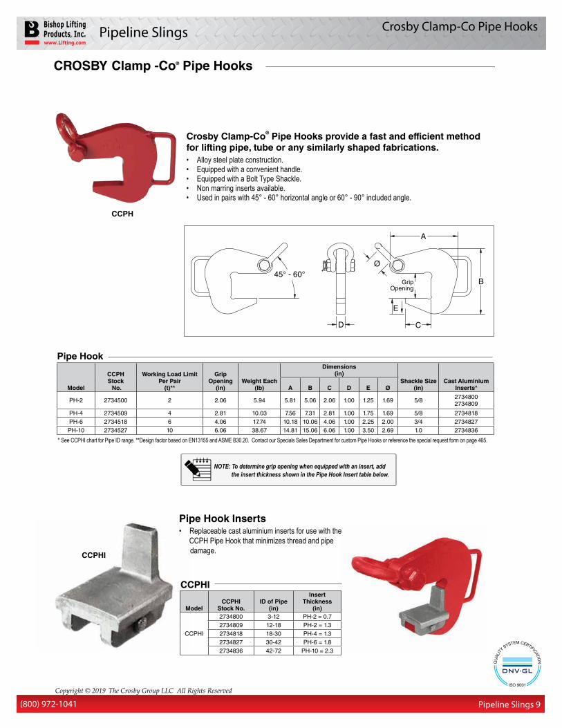
Crosby Clamp-Co® Pipe Hooks provide a fast and efficient method for lifting pipe, tube or any similarly shaped fabrications.• Alloy steel plate construction.• Equipped with a convenient handle.• Equipped with a Bolt Type Shackle.• Non marring inserts available.• Used in pairs with 45° - 60° horizontal angle or 60° - 90° included angle.
Pipe Hook Inserts• Replaceable cast aluminium inserts for use with the CCPH Pipe Hook that minimizes thread and pipe damage.
CCPH
CCPHI
Model
CCPHStock No.
Working Load LimitPer Pair
(t)**
Grip Opening
(in)Weight Each
(lb)
Dimensions(in)
Shackle Size(in)
Cast Aluminium Inserts*A B C D E Ø
PH-2 2734500 2 2.06 5.94 5.81 5.06 2.06 1.00 1.25 1.69 5/8 2734800 2734809
PH-4 2734509 4 2.81 10.03 7.56 7.31 2.81 1.00 1.75 1.69 5/8 2734818PH-6 2734518 6 4.06 17.74 10.18 10.06 4.06 1.00 2.25 2.00 3/4 2734827PH-10 2734527 10 6.06 38.67 14.81 15.06 6.06 1.00 3.50 2.69 1.0 2734836
Pipe Hook
* See CCPHI chart for Pipe ID range. **Design factor based on EN13155 and ASME B30.20. Contact our Specials Sales Department for custom Pipe Hooks or reference the special request form on page 465.
ModelCCPHI
Stock No.ID of Pipe
(in)
Insert Thickness
(in)
CCPHI
2734800 3-12 PH-2 = 0.72734809 12-18 PH-2 = 1.32734818 18-30 PH-4 = 1.32734827 30-42 PH-6 = 1.82734836 42-72 PH-10 = 2.3
CCPHI
CROSBY Clamp-Co® Barrier / Curb Grabs CROSBY Clamp -Co® Pipe Hooks
NOTE: To determine grip opening when equipped with an insert, add the insert thickness shown in the Pipe Hook Insert table below.
Pipeline Slings
(800) 972-1041 (800) 972-1041
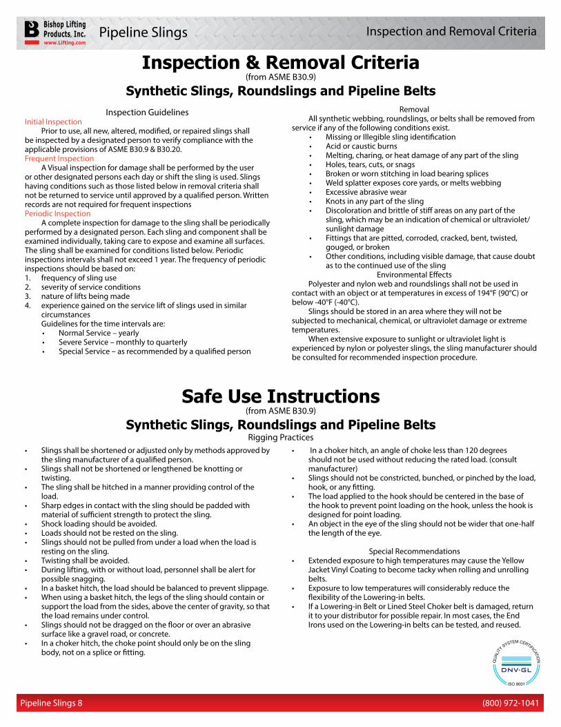
Inspection & Removal Criteria(from ASME B30.9)
Synthetic Slings, Roundslings and Pipeline Belts
Safe Use Instructions(from ASME B30.9)
Synthetic Slings, Roundslings and Pipeline BeltsRigging Practices
Inspection Guidelines Initial Inspection
Prior to use, all new, altered, modified, or repaired slings shall be inspected by a designated person to verify compliance with the applicable provisions of ASME B30.9 & B30.20.Frequent Inspection
A Visual inspection for damage shall be performed by the user or other designated persons each day or shift the sling is used. Slings having conditions such as those listed below in removal criteria shall not be returned to service until approved by a qualified person. Written records are not required for frequent inspectionsPeriodic Inspection
A complete inspection for damage to the sling shall be periodically performed by a designated person. Each sling and component shall be examined individually, taking care to expose and examine all surfaces. The sling shall be examined for conditions listed below. Periodic inspections intervals shall not exceed 1 year. The frequency of periodic inspections should be based on:1. frequency of sling use2. severity of service conditions3. nature of lifts being made4. experience gained on the service lift of slings used in similar
circumstancesGuidelines for the time intervals are:• Normal Service – yearly• Severe Service – monthly to quarterly• Special Service – as recommended by a qualified person
Removal All synthetic webbing, roundslings, or belts shall be removed from
service if any of the following conditions exist.• Missing or Illegible sling identification• Acid or caustic burns• Melting, charing, or heat damage of any part of the sling• Holes, tears, cuts, or snags• Broken or worn stitching in load bearing splices• Weld splatter exposes core yards, or melts webbing• Excessive abrasive wear• Knots in any part of the sling• Discoloration and brittle of stiff areas on any part of the
sling, which may be an indication of chemical or ultraviolet/sunlight damage
• Fittings that are pitted, corroded, cracked, bent, twisted, gouged, or broken
• Other conditions, including visible damage, that cause doubt as to the continued use of the sling
Environmental EffectsPolyester and nylon web and roundslings shall not be used in
contact with an object or at temperatures in excess of 194°F (90°C) or below -40°F (-40°C).
Slings should be stored in an area where they will not be subjected to mechanical, chemical, or ultraviolet damage or extreme temperatures.
When extensive exposure to sunlight or ultraviolet light is experienced by nylon or polyester slings, the sling manufacturer should be consulted for recommended inspection procedure.
• Slings shall be shortened or adjusted only by methods approved by the sling manufacturer of a qualified person.
• Slings shall not be shortened or lengthened be knotting or twisting.
• The sling shall be hitched in a manner providing control of the load.
• Sharp edges in contact with the sling should be padded with material of sufficient strength to protect the sling.
• Shock loading should be avoided.• Loads should not be rested on the sling.• Slings should not be pulled from under a load when the load is
resting on the sling.• Twisting shall be avoided.• During lifting, with or without load, personnel shall be alert for
possible snagging.• In a basket hitch, the load should be balanced to prevent slippage.• When using a basket hitch, the legs of the sling should contain or
support the load from the sides, above the center of gravity, so that the load remains under control.
• Slings should not be dragged on the floor or over an abrasive surface like a gravel road, or concrete.
• In a choker hitch, the choke point should only be on the sling body, not on a splice or fitting.
• In a choker hitch, an angle of choke less than 120 degrees should not be used without reducing the rated load. (consult manufacturer)
• Slings should not be constricted, bunched, or pinched by the load, hook, or any fitting.
• The load applied to the hook should be centered in the base of the hook to prevent point loading on the hook, unless the hook is designed for point loading.
• An object in the eye of the sling should not be wider that one-half the length of the eye.
Special Recommendations• Extended exposure to high temperatures may cause the Yellow
Jacket Vinyl Coating to become tacky when rolling and unrolling belts.
• Exposure to low temperatures will considerably reduce the flexibility of the Lowering-in belts.
• If a Lowering-in Belt or Lined Steel Choker belt is damaged, return it to your distributor for possible repair. In most cases, the End Irons used on the Lowering-in belts can be tested, and reused.
Pipeline Slings 8
Inspection and Removal Criteria
M E M B E R
Products sold by:
BLP-PSC-9/2019
Pipeline Slings Catalog
Lowering-in Belts Head Irons Lined Steel Choker Belts Roundslings Rigging Accessories
Houston, TX(713) 674-2266
Tulsa, OK(918) 582-1807