pitch control of an aircraft using artificial intelligence
TRANSCRIPT

____________________________________________________________________________________________
*Corresponding author: E-mail: [email protected];
Journal of Scientific Research & Reports1(1): 1-16, 2012; Article no. JSRR.2012.001
SCIENCEDOMAIN internationalwww.sciencedomain.org
Pitch Control of an Aircraft Using ArtificialIntelligence
A.B. Kisabo1*, F. A. Agboola2, C.A. Osheku1, M. A. L. Adetoro1
and A.A. Funmilayo1
1Center for Space Transport and Propulsion (CSTP) Epe, Lagos, Nigeria.2Engineering and Space Systems (ESS) of NASRDA Abuja, Lagos, Nigeria.
Authors’ contributions
This work was carried out in collaboration between all authors. Author ABK designed thestudy, performed the numerical simulations & analysis and wrote the first draft of the
manuscript. Authors FAA and CAO managed the analysis of the study and public release ofinformation. Author MALA engineered hardware implementation. Author AAF verified HIL
simulation and literature searches. All authors read and approved the final manuscript.
Received 9th August 2012Accepted 14th October 2012
Published 16th November 2012
ABSTRACT
This paper presents the investigation into the design, simulation and analysis of twoautopilots: a fuzzy Proportional-Integral-Derivative (PID) controller and, its hybrid with aPID controller for the control of pitch plane dynamics of an aircraft. The Mamdani-typefuzzy inference system is employed for the Fuzzy Inference System (FIS) in the fuzzylogic controller design. The dynamic modeling of system begins with a derivation ofsuitable mathematical model to describe the longitudinal motion of an aircraft. Thisresearch set the platform for thorough investigation into the various structures availablefor PID-FLC and its hybrids. Considering hardware implementation challenges andlimitations, not all PID-FLC and its hybrid structures are viable. The PID-FLC isconstructed as a parallel structure of a PD-FLC and a PI-FLC, with the output signal of thecontrol loop, y serving as the input for the derivative parameter of the PD-FLC. The outputof the PID-FLC is formed by algebraically adding the outputs of the two fuzzy controlblocks as suggested in Guanrong et al., 2000. Also, the proposed hybrid fuzzy PIDautopilot consists of the PID-FLC with a traditional PID controller structured byalgebraically adding the outputs of the two control blocks. Result of simulation inMATLAB®/Simulink® shows that the proposed PID-FLC autopilot gave an unacceptable
Research Article
Kisabo et al.; JSRR, Article no. JSRR.2012.001
2
trend when subjected to a step response and Dirac’s delta impulse responseinvestigation. While the intelligent hybrid autopilot; PID-FLC with PID controller gave anacceptable time response characteristics.
Keywords: Aircraft; fuzzy logic control; pitch dynamics; autopilot; Matlab®/Simulink®.
1. INTRODUCTION
The rapid advancement of aircraft design from the very limited capabilities of the Wrightbrothers first successfully airplane to today’s high performance military, commercial andgeneral aviation aircraft require the development of many technologies, these areaerodynamics, structures, materials, propulsion and flight control.
The development of automatic control system has played an important role in the growth ofcivil and military aviation. Modern aircraft include a variety of automatic control system thataids the flight crew in navigation, flight management and augmenting the stabilitycharacteristics of the airplane. For this situation an autopilot is designed that control the pitchof aircraft that can be used by the flight crew to lessen their workload during cruising andhelp them land the aircraft during adverse weather condition. The autopilot is an elementwithin the flight control system. It is a pilot relief mechanism that assists in maintaining anattitude, heading, altitude or flying to navigation or landing references. Designing an autopilotrequires control system theory background and knowledge of stability derivatives at differentaltitudes and Mach numbers for a given airplane [1, 2].
One of the major problems of flight control system is due to the combination of nonlineardynamics, modeling uncertainties and parameter variation in characterizing an aircraft andits operating environment. The aircraft motion in free flight is extremely complicated.Generally, aircraft fly in three-axis plane by controlling aileron, rudder and elevator. FlightDynamics, as it is called now has its roots way back to the work of W.J. Duncan, which isperhaps not surprising since Duncan was the first Professor of Aerodynamics at Cranfieldsome 50 years ago. The classical linearized theory of stability and control of aircraft istimeless, it is brilliant in its relative simplicity and it is very securely anchored in the domainof the aerodynamicist [3].
The study of airplane stability and control is primarily focused on moments about theairplane center of gravity. A balanced (i.e., trimmed) airplane will have zero moment aboutits center of gravity. There are numerous places where moments can be generated in anairplane such as moments contributed by the wing, the fuselage, the engine propulsion, thecontrols (e.g., elevator, aileron, rudder, canard, etc.) and the vertical and horizontal tailsurfaces. Note that the gravity force does not contribute any moment to the airplane since itis, by definition, applied at the center of gravity.
They are designed to change and control the moments about the roll, pitch and yaw axes.The control system of the aircraft is divided into two portions, longitudinal and lateral control.The key motion variables in the lateral axis correspond to sideslip (with sideslip angle β, orside velocity v), roll (with roll rate p) and yaw (with yaw rate r). Primary controls are rudder δrand ailerons δa. The lateral motion of an airplane is described in terms of two tightly coupledmotions: yaw about the z-body axis (i.e. directional) and roll about the x-body axis (i.e.lateral). There are numerous components that contribute to the yawing moment in the

Kisabo et al.; JSRR, Article no. JSRR.2012.001
3
airplane when perturbed in the lateral motion variables. Yawing moment generated at thewing is developed mainly from perturbed motions in sideslip β and roll rate p in the lateralaxis. Due to sideslip, there is an increase in drag on one side of the wing that is moreperpendicular to the flow and thereby would produce a yawing moment. If the wing is sweptaft, then this yawing moment is stabilizing (i.e. producing a positive yawing moment to apositive sideslip). Other parts of the aircraft that contribute to the yawing moment arefuselage, vertical tail, propulsion, rudder, aileron and spoiler. The rolling motion is generallyaffected by the motion variables in yaw rate r, sideslip β and roll p. The components thatcontribute mostly to the rolling moment are the wing, the vertical tail, the ailerons (located onthe wing and the rudder [4].
In longitudinal control, the elevator controls pitch or the longitudinal motion of aircraft system.The elevator is situated at the rear of the airplane running parallel to the wing that housesthe ailerons. Pitch control is a longitudinal problem and this work presents a design of anautopilot that controls the pitch of an aircraft. Pitch is controlled by the rear part of the tailplane's horizontal stabilizer being hinged to create an elevator. By moving the elevatorcontrol backwards the pilot moves the elevator up (a position of negative camber) and thedownwards force on the horizontal tail is increased. The angle of attack on the wingsincreased so the nose is pitched up and lift is generally increased. In micro-lights and hanggliders the pitch action is reversed and the pitch control system is much simpler, so when thepilot moves the elevator control backwards it produces a nose-down pitch and the angle ofattack on the wing is reduced. The pitch angle of an aircraft is controlled by adjusting theangle and therefore the lift force of the rear elevator [5]. Lot of works has been done in thepast to control the pitch of an aircraft for the purpose of flight stability and yet this researchstill remains an open issue in the present and future works.
Following the introduction is Section 2 where the mathematical derivation for an aircraft pitchplane model in transfer function is put forward. Section 3 gives mathematical description of asimple actuator with its basic characteristics that drives the plant. In section 4, Fuzzy Logic isintroduced from the standpoint of control. This section also includes a brief description ofhow a Fuzzy Inference System (FIS) is built from a MATLAB®/Simulink® GUI interface.Under this same section we delved into the theory and design consideration for a typicalFuzzy PID autopilot and hence its hybrid. The autopilots simulations results are alsopresented here in graphical form. In section 5, the results of simulation are discussed. This isimmediately followed by a conclusion in section 6. Finally, the areas for future improvementsare put forward in a section 7.
2. MATHEMATICAL MODEL FOR PITCH CONTROL
In order to reduce the complexity of analysis, under certain assumptions, the equationgoverning motion of an aircraft can be separated into two groups, namely the longitudinaland lateral equations. This section provides a brief description on the modeling of pitchcontrol longitudinal equation of aircraft, as a basis of a simulation environment fordevelopment and performance evaluation of the proposed controller techniques. The systemof longitudinal dynamics is considered in this investigation and derived in the transferfunction.
The pitch control system considered in this work is shown in Fig. 1 where Xb, Yb and Zbrepresent the aerodynamics force components. θ, Ф and δe represent the orientation ofaircraft (pitch angle) in the earth-axis system and elevator deflection angle.

Kisabo et al.; JSRR, Article no. JSRR.2012.001
4
The forces, moments and velocity components in the body fixed coordinate of aircraftsystem can be described as showed in Fig. 2. The aerodynamics moment components forroll, pitch and yaw axis are represent as L, M and N. The term p, q, r represent the angularrates about roll, pitch and yaw axis while term u, v, w represent the velocity components ofroll, pitch and yaw axis. α and β represents the angle of attack and sideslip respectively.
Fig. 1. Longitudinal dynamics description of an aircraft
The parameters considered for the aircraft modeling and analysis include the dimensionalderivatives Q=36.8Ib/ft2, QS=6771Ib, QSĉ=3859ft.lb and ĉ/2u0=0.016. Note, that dimensionalderivative and stability derivative parameters used for modeling the aircraft in this researchare in the their original units because in dealing with aerospace systems it is saver to do so,conversion to SI unit might be challenging and introduce errors [6]. The longitudinaldynamics also control the forward speed and altitude of the aircraft.
Fig. 2. Forces and moment acting on an aircraft
A few assumption need to be considered before continuing with the modeling process. First,the aircraft is at a steady state cruising at constant altitude and velocity, thus the thrust anddrag are cancel out and the lift and weight balance out each other. Second, the change inpitch angle does not change the speed of an aircraft under any circumstance. Also, theatmosphere in which the plane flies is assumed undisturbed, thus forces and moment due

Kisabo et al.; JSRR, Article no. JSRR.2012.001
5
atmospheric disturbance are considered zero. Hence, considering Fig. 1 and Fig. 2, thefollowing dynamic equations describe the longitudinal dynamics of a typical aircraft;
Force equations:
( ).X mgS m u qv rv (1)
( ).Z mgC C m w pv qu (2)
Momentum equation:
2 2( ) ( ).y x z xzM I q rq I I I P r (3)
The longitudinal stability derivatives parameter used are denoted in Table 1.
Table 1. Longitudinal derivative stability parameters
Longitudinal derivatives X-Force(s-1) Z-Force(F-1) Pitching moment(FT-1)Rolling velocitiesYawing velocities
Xu=-0.0045Xw=0.036
Zu=-0.369Zw=-2.02
Mu=0Mw= -0.051
Xẇ=0 Zẇ=0 Mẇ=0Angle of attack Xα=0 Zα=-335.42 Mα=-8.8
Pitching rateElevator deflection
Xἀ=0Xq=0Xδe=0
Zἀ=0Zq=0Zδe=-28.15
Mἀ=-0.8976Mq=-2.05Mδe=-11.874
It is required to completely solve the aircraft problem with the following assumption:
Rolling rate, is given as,p S (4)
Yawing rate, as,q C C S (5)
Pitching rate,r C C S (6)
Pitch angle,qC rS (7)
Roll angle,p qS T rC T (8)
Yaw angle( )sec .qS rC (9)
Equation (1), equation (2) and equation (3) should be linearized using small disturbancetheory. The equations are replaced by a reference value plus a perturbation or disturbance,as shown in (10).

Kisabo et al.; JSRR, Article no. JSRR.2012.001
6
0 ,u u u 0 ,v v v 0 .w w w
0 ,p p p 0 ,q q q 0 .r r r (10)
0 ,X X X 0 ,M M M 0 .Z Z Z
0 . For convenience, the reference flight condition is assumed to be symmetric and thepropulsive forces are assumed to remain constant. This implies that,
0 0 0 0 0 0 0 0.v p q r w (11)
After linearization the following equations were obtained for the longitudinal dynamics, of theaircraft keeping in mind that (12), (13) are the force equations and (14) momentum equation.
0( cos ) ,u w e e
dX u X w g X
dx
(12)
0 0(1 ) ( ) sin ,u w w q e e
d dZ u Z Z w u Z g Z
dt dt
(13)
2
2.u w w q e e
d d dM u M M w M M
dt dt dt
(14)
By manipulating (12), (13) and (14) and substituting the parameters values of thelongitudinal stability derivatives in Table 1, the following transfer function for the change inthe pitch rate to the change in elevator deflection angle is given as:
0 0 02
0 0
( / ) ( / / )( ),
( ) ( / ) ( / )e e e e
e q q
M M Z u s M Z u M Z uq s
s s M M Z u s Z M u M
(15)
The transfer function of the change in pitch angle to the change in elevator angle can beobtained from the change in pitch rates to the change in elevator angle in the following way;
,q (16)( ) ( ),q s s s (17)
( ) 1 ( ). .
( ) ( )e
s q s
s s s
(18)
Hence, the transfer function for the pitch system dynamics of an aircraft can be described by(19). For the typical values of stability derivatives given in Table 1, (20) will serve as themathematical model depicting the longitudinal dynamics of the aircraft that will be used forthe controller design, simulation and analysis [7].
0 0 02
0 0
( / ) ( / / )( ) 1. ,
( ) ( / ) ( / )e e e e
e q q
M M Z u s M Z u M Z uq s
s s s M M Z u s Z M u M
(19)

Kisabo et al.; JSRR, Article no. JSRR.2012.001
7
3 2
( ) 11.7304 22.578.
( ) 4.9676 12.941e
s s
s s s s
(20)
3. ACTUATOR DYNAMICS
For simplicity, a first order model of an actuator is employed with the transfer function asgiven in (21). The actuator device time constant τ = 0.0167sec., is employed:
1( ) .
1H s
s
(21)
4. FUZZY LOGIC CONTROL (FLC)
Here, is a superficial introduction to fuzzy logic and it basic constituents as regards control ofdynamic systems. Also, we considered how to build such controllers in Simulink®
environment of MATLAB®. Simulations of the built controllers and their results are alsopresented.
Fuzzy logic controllers fall into the class of Intelligent Control Systems. An intelligent controlsystem combines the techniques from the fields of Artificial Intelligence (AI) with those ofcontrol engineering to design autonomous systems that can sense, reason, and plan, learnand act in an intelligent manner. Intelligent behavior is therefore the ability to reason, planand learn, which in turn requires access to knowledge. Artificial Intelligence is a by-productof the Information Technology (IT) revolution, and is an attempt to replace humanintelligence with machine intelligence. An intelligent control system combines the techniquesfrom the fields of AI with those of control engineering to design autonomous systems thatcan sense, reason, plan, learn and act in an intelligent manner. Such a system should beable to achieve sustained desired behavior under conditions of uncertainty, which includes.
Uncertainty in the plant mode. Unpredictable environmental changes. Incomplete, inconsistent or unreliable sensor information. Actuator malfunction.
Fuzzy logic tool was introduced in 1965, by Lofti Zadeh, and is a mathematical tool fordealing with uncertainty. It offers to a soft computing partnership the important concept ofcomputing with words. It provides a technique to deal with imprecision and informationgranularity. The fuzzy theory provides a mechanism for representing linguistic constructssuch as ‘many’, ’low’, ‘medium’, ‘often’, ’few’. In general the fuzzy logic provides an inferencestructure that enables appropriate human reasoning capabilities [8].
Fuzzy Logic Control (FLC) system is one of the main developments and successes of fuzzysets and fuzzy logic. A FLC is characterized by four modules: fuzzifier; defuzzifier; inferenceengine and rule base.
In terms of inference process there are two main types of Fuzzy Inference Systems (FIS):the Mamdani-type and the Takagi Sugeno Kang (TSK)-type. In terms of use, the MamdaniFIS is more widely used, mostly because it provides reasonable results with a relatively

Kisabo et al.; JSRR, Article no. JSRR.2012.001
8
simple structure, and also due to the intuitive and interpretable nature of the rule base. Thefuzzy rule-base consists of a set of antecedent consequent linguistic rules of the form:
IF L THEN M. (22)
This style of fuzzy conditional statement is often called a ‘Mamdani’- type rule, afterMamdani (1976) who first used it in a fuzzy rule-base to control steam plant. The rule-base isconstructed using a prior knowledge from either one or all of the following sources: Physical laws that govern the plant dynamics. Data from existing controllers. Imprecise heuristic knowledge obtained from experience expert.
If the third item above is used, then knowledge of the plant mathematical model is notrequired. Once the inputs are fuzzified, the corresponding input fuzzy sets are passed to theinference engine that processes current inputs using the rules retrieved from the rule base[8].
4.1 The Rule Base
In our proposed FLC, there are two inputs to the fuzzy inference system. One is the controlerror e(k), which is the difference between the reference signal r(k) and the output signaly(k), the other one is the change in this error Δe(k). These two inputs, defined as in (24) and(25), are first fuzzified and converted to fuzzy membership values that are used in the rulebase in order to execute the related rules so that an output can be generated.
( ) ( ) ( ),e k r k y k (23)( ) ( ) ( 1).e k e k e k (24)
The fuzzy rule base, which may also be called the fuzzy decision table, is the unit mappingtwo crisp inputs, e(k) and Δe(k) to the fuzzy output space defined on the universe ofΔu(k).There are nine rules that have been utilized in designing the controller and the rulesare defined in Table 2. The knowledge required to generate the fuzzy rules can be derivedfrom an offline simulation. However, it has been noticed that, for monotonic systems, asymmetrical rule table is very appropriate, although sometimes it may need slightadjustments based on the behavior of the specific system. If the system dynamics are notknown or are highly nonlinear, trial-and-error procedures and experience play an importantrole in defining the rules. Each fuzzy set consists of three types of membership function,which are negative (N), zero (Z) and positive (P).
In this research, the triangular membership functions are chosen for each fuzzy set. Theuniverse of discourse is set between -0.4 to 0.4 that implies the range of pitch angle (±0.4radian).The appropriate membership function to represent each fuzzy set need to be definedand each fuzzy set must have the appropriate universe of discourse. In addition, themembership functions are evenly distributed so that the tuning process of the controller canbe easily done [9].
4.2 Building the Fuzzy Inference System (FIS)
Using the FIS editor of MATLAB, the two inputs to the fuzzy controller are the error (e) whichmeasures the system performance and the rate at which the error changes (Δe), whereas

Kisabo et al.; JSRR, Article no. JSRR.2012.001
9
the output of the control signal (Δu). A Mamdani type FLC is used with triangularmembership functions for the inputs and output. The FLC uses MIN for t-norm operation,MAX for s-norm operation, MAX for aggregation, MIN for implication, and CENTROID fordefuzzification. The membership function maps the crisp values into fuzzy variables. Thechoice of membership function has an important bearing on the performance of the fuzzylogic controller. The triangular membership was chosen for the two inputs and the output ofthe synthesized fuzzy logic controller. This was simply selected from the FIS editor interface[10].
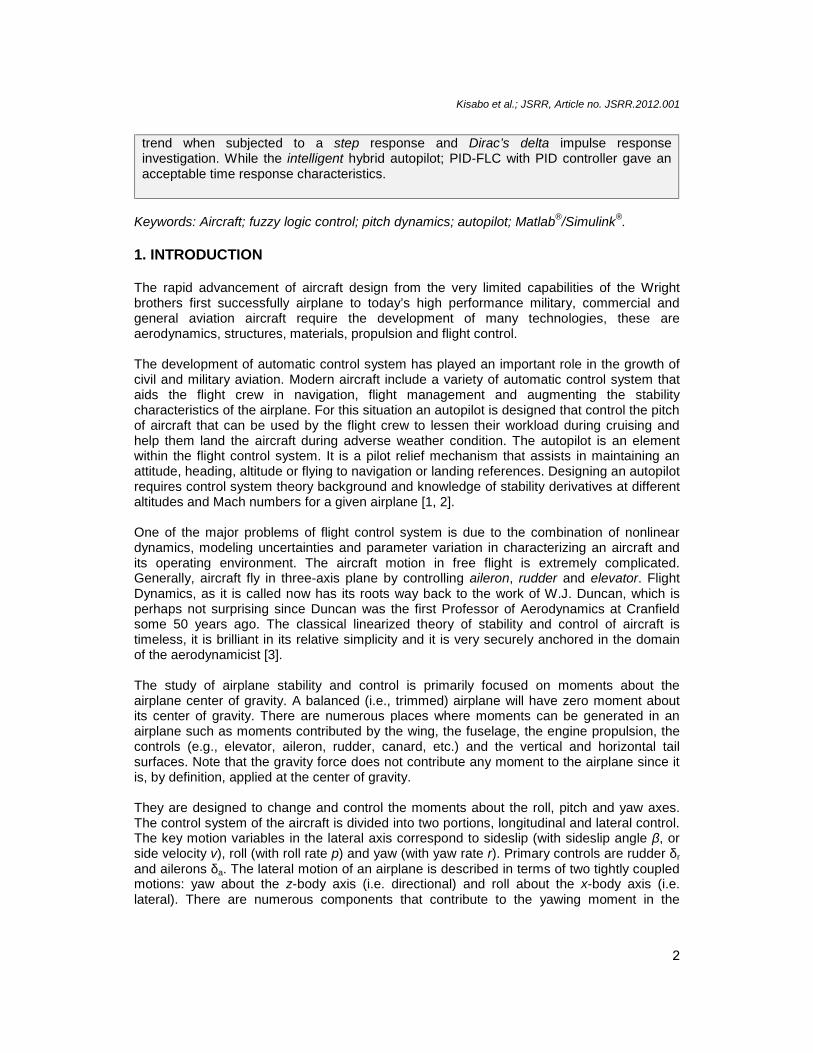
The Rule editor is used to input the 9 rules given in Table 2. It contains a large editable textfield for displaying and editing rules. The Boolean operator ‘min’ is used for the verbalconnector ‘and’ to simulate the input space of the rules. In Fig.3, the two yellow columns arefor the two inputs and the blue column for the control output. Finally, a three dimensionalmapping of the two inputs and the control is depicted in a three dimensional plot as shown inFig.4.
Table 2.Fuzzy logic rules for the aircraft controller design
Number RRu Rules1.2.3.
If (e is N) and (Δe is N) then ( Δu is N)If (e is N) and (Δe is Z) then (Δu is N)If (e is N) and (Δe is P) then (Δu is N)
4. If (e is Z) and (Δe is N) then (Δu is N)5.6.7.8.9.
If (e is Z) and (Δe is Z) then (Δu is Z)If (e is Z) and (Δe is P) then (Δu is P)If (e is P) and (Δe is N) then (Δu is P)If (e is P) and (Δe is Z) then (Δu is P)If (e is P) and (Δe is P) then (Δu is P)
Fig. 3. The fuzzy inference in the rule viewer GUI
Kisabo et al.; JSRR, Article no. JSRR.2012.001
9
the output of the control signal (Δu). A Mamdani type FLC is used with triangularmembership functions for the inputs and output. The FLC uses MIN for t-norm operation,MAX for s-norm operation, MAX for aggregation, MIN for implication, and CENTROID fordefuzzification. The membership function maps the crisp values into fuzzy variables. Thechoice of membership function has an important bearing on the performance of the fuzzylogic controller. The triangular membership was chosen for the two inputs and the output ofthe synthesized fuzzy logic controller. This was simply selected from the FIS editor interface[10].
The Rule editor is used to input the 9 rules given in Table 2. It contains a large editable textfield for displaying and editing rules. The Boolean operator ‘min’ is used for the verbalconnector ‘and’ to simulate the input space of the rules. In Fig.3, the two yellow columns arefor the two inputs and the blue column for the control output. Finally, a three dimensionalmapping of the two inputs and the control is depicted in a three dimensional plot as shown inFig.4.
Table 2.Fuzzy logic rules for the aircraft controller design
Number RRu Rules1.2.3.
If (e is N) and (Δe is N) then ( Δu is N)If (e is N) and (Δe is Z) then (Δu is N)If (e is N) and (Δe is P) then (Δu is N)
4. If (e is Z) and (Δe is N) then (Δu is N)5.6.7.8.9.
If (e is Z) and (Δe is Z) then (Δu is Z)If (e is Z) and (Δe is P) then (Δu is P)If (e is P) and (Δe is N) then (Δu is P)If (e is P) and (Δe is Z) then (Δu is P)If (e is P) and (Δe is P) then (Δu is P)
Fig. 3. The fuzzy inference in the rule viewer GUI
Kisabo et al.; JSRR, Article no. JSRR.2012.001
10
Fig. 4. Three-dimensional plot of the output surface
4.3 Fuzzy PID Autopilot
A PID fuzzy controller is a controller that takes error, summation of error and rate of changeof error (rate for short) as inputs. Fuzzy controller with three inputs is difficult and not easy toimplement, because it needs a large number of rules and memory (Leonid, 1997).Generally,to represent PID-FLC, it is required to design a fuzzy inference system with three inputs thatrepresent the proportional, derivative, and integral components, and each one of them canhave up to 8 fuzzy sets. Therefore, the maximum number of required fuzzy rules in anysituation is 8x8x8 =512 rules. But for this research only 3 fuzzy sets were used for the rulebase, thus the maximum rules it would yield would be 3x3x3=27 if three inputs were to beimplemented.
The PID-FLC can be constructed as a parallel structure of a PD-FLC and a PI-FLC, suchthat the input signal for the derivative gain to the PD-FLC is the control loop output signal, y[11]. The output of the PID-FLC is formed by algebraically adding the outputs of the twofuzzy control blocks, suggested by Leonid. This will reduce the number of maximum rulespossible to 8x8 +8x8= 128 rules. Thus, for this research we will end up with 3x3+3x3=18rules, considering the three fuzzy sets given in Table 2.
It is interesting to note that the PID-FLC structure proposed in (Guanrong et al., 2000) whichis the crux of this research proposes that the gain Kp2 in Fig. 5to have a numerical value of -1. This turns-out to distort simulation result, but on adopting the value of 1, simulation resultwas appreciated. Hence, the parameter Kp2=1 was used throughout the simulation in thisresearch. Though we strongly advice the trial of both Kp2=-1 first in any design, if simulationresult is not appreciated only then will it be justified to use Kp2=1 as done in this research.
The Simulink model for the fuzzy PID logic control of the aircraft pitch dynamics wasimplemented by linking the FIS designed above with a Simulink model for the autopilot.

Kisabo et al.; JSRR, Article no. JSRR.2012.001
11
Manual tuning means via trial-and-error was used to obtain the proportional, derivative andoutput gains associated with the controller [12].
Fig.5.Simulink model of the fuzzy PID autopilot
From investigating the Eigen values of the pitch plane aircraft model we were able to deducethe most appropriate solver(s) for this simulation. The aircraft has the following Eigen values:λ1=0, λ2=-2.4838+2.6021i and λ3=-2.4838-2.6021i. Thus, the system is unstable, theSimulink solver ode45 (Dorman Prince)-default and ode113 (Adam’s Method) are the twomost likely solvers to be used for the simulation. After experimenting with both, ode113 wasfound to be most suitable [13]. MATLAB/Simulink version 2010a was used for all simulationin this research.
From the trend observed in Fig. 6, the need to modify this autopilot is inevitable. Studies inapplied research show that it is even more interesting to combine the use of fuzzy logiccontrollers with traditional controllers in order to make these controllers more robust.
Fig. 6.Simulation result of fuzzy PID autopilot
Dirac's Delta function
U_c1.4
ko
teta_II
t
Step
1
Kp2
0.9
Kp
1.3Ko
0.38
Ki
0.25
Kd
1/s
Fuzzy LogicController_II
Fuzzy LogicController_I
du/dt
11.7304s+22.578
s +4.9676s +12.941s3 2
Aircraft Pitch Model
s+60
60
Actuator
0 5 10 15 20-0.2
0
0.2
0.4
0.6
Pitc
h an
gle(
rad)
Time(sec)
Ref.teta

Kisabo et al.; JSRR, Article no. JSRR.2012.001
12
4.4 Hybrid Fuzzy PID Autopilot
The traditional control, which includes the classical feedback control, modern control theoryand large-scale control system theory, has encountered many difficulties in its applications.The design and analysis of traditional control systems are based on their precisemathematical models, which are usually very difficult to achieve, owing to the complexity,nonlinearity, time varying and incomplete characteristics of the existing practical systems.One of the most effective ways to solve the problem is to use the technique of hybridmethodology of the traditional and intelligent control techniques.
For the fuzzy PID controllers simulated in this work (Fig. 5), we chose to design a hybridversion of it by adding a PID controller to the existing designs. Our desire is to get rid of themild oscillation in the result obtained in Fig. 6. For the hybrid fuzzy PID autopilot we proposethe scheme as shown in Fig. 7. Note also that the solver ode113 was used for the simulationhere.
Fig. 7. Simulink model of the hybrid fuzzy PID autopilot
The proposed hybrid autopilot possesses two main parts: the classical PID and fuzzy PIDcontrollers. Both control efforts are added algebraically to drive the plant via an actuator.Note, attempts were made to build the hybrid autopilot by including the PID controller at theoutput of the fuzzy logic controller signal but simulation proved abortive.
U_c
Dirac's Delta function
1.4
ko
teta_hybd_II
t
Step
PID(s)
PID Controller
1
Kp2
0.9
Kp
1.3Ko
0.4
Ki
0.24
Kd
1/s
Fuzzy LogicController_II
Fuzzy LogicController_I
du/dt
11.7304s+22.578
s +4.9676s +12.941s3 2
Aircraft Pitch Model
s+60
60
Actuator

Kisabo et al.; JSRR, Article no. JSRR.2012.001
13
A standard PID controller is also known as the “three-term” controller, whose transferfunction is generally written in the “ideal form” as
( ) ,IPID p D D
I
KG s K K T s
T s (25)
Where Kp is the proportional gain, KI the integral gain, KD the derivative gain, TI the integraltime constant and, TD the derivative time constant. In this paper, the classical PID and fuzzyPID controller are combined by algebraically summing both controllers via a summationblock in the Simulink modeling environment. The MATLAB/Simulink simulation model of theproposed intelligent hybrid controller with a step function and Dirac’s Delta impulse is alsonecessary to ascertain the behavior of the hybrid controller. The simulation results aredepicted in Fig. 8.
Fig. 8. Simulation result for the hybrid fuzzy PID autopilot-step and Dirac’s response
5. RESULTS AND DISCUSSION
It is clearly seen from the simulation result in Fig. 6 that the aircraft fuzzy PID autopilot givenin Fig. 5 is inadequate for set-point tracking of a reference pitch angle of about 23º (0.4radians). The major drawback is observed at about 20 seconds into the simulation time –thebeginning of a mild oscillation. When the PID-FLC autopilot was subjected to a Dirac’simpulse investigation, the same oscillatory trend was observed at the same time.
From simulation results in Fig. 8, it is evident that the hybrid autopilot is capable of robustperformance. It can be seen that the undesired oscillatory trend that plagued the PID-FLCautopilot is absence here after the step response and Dirac’s delta impulse responseinvestigations. For this hybrid autopilot, the traditional PID controller design consist of thefollowing parameters; Kp=0.15, KI=0.032, KD=-0.33 and filter coefficient, N=0.36. It is also ofimportance here to note that the time response characteristics of this Intelligent hybridautopilot are: rise time, tr=0.7s, percentage overshoot, PO=15%, settling time, ts=15s and asteady state error, SSE=0. Note that from Fig. 6, the percentage overshoot is acceptable,hence the integral and derivative gains of the traditional PID controller played a crucial rulein the result we obtained in Fig.7.
It is also of importance to note here that other possible hybrid PID structures whereinvestigated (those with the output of the PID-FLC control signal serving as input to thetraditional PID controller), simulation proved abortive. While that implemented in this workwas successful, that is by adding the control signals from both the PID-FLC and the
0 5 10 15 20-0.2
0
0.2
0.4
0.6
Time(sec)
Pitc
h an
gle(
rad)
ref.teta-hybd
0 5 10 15 20-0.5
0
0.5
1
Time(sec)
Pitc
h an
gle(
rad)
ref.teta-hybd

Kisabo et al.; JSRR, Article no. JSRR.2012.001
14
traditional PID controller algebraically. Hence the combined control signals driving the plantvia an actuator.
Hardware implementation of fuzzy logic controllers has many requirements, one of which islimitations concerning the structure. Many of the hybrid fuzzy controllers simulated inliterature have limitations and challenges with their structure when hardware implementationis require. It is desirable to simplify the structure of the hybrid fuzzy PID controller to offerhigher flexibility versus low-chip resources, especially when considering Field ProgrammableGate Array platform (FPGA) for hardware implementation. The algorithm was implementedusing the Simulink® plug in, System Generator, which complements traditional HardwareDescription Language (HDL) by providing a higher level graphical language for thedevelopment of FPGA designs. The design is then translated into the lower level required bythe Xilinx’s ISE program. By utilizing this graphical based higher level of abstraction at thedesign entry level, the requirement of a detailed knowledge of HDL languages is no longerrequired. Because of this new environment the time required to implement the previouslydeveloped control design on the FPGA is reduced.The final verification of the FPGA designwas a hardware-in-the-loop simulation utilizing a Xilinx prototyping board directly withSimulink through a standard USB connection by synchronizing the FPGA clock to Simulinktime [14, 15, and 16].
This autopilot is design for a general aviation amphibian aircraft prototype [17] which iscurrently under construction at CSTP, though full flight testing has not been carried out.
6. CONCLUSIONS
In this paper, we designed and simulated two autopilots; first a PID-FLC and second, ahybrid of PID-FLC with a traditional PID controller. The autopilot design began with asuitable derivation of pitch plane dynamics of the aircraft to be controlled. The fuzzy logiccontroller was design in MATLAB®/Simulink® Fuzzy Inference System (FIS). The structure ofthe hybrid autopilot was successfully simulated as an algebraic sum of two controllers; aconvectional PID controller and a PID-fuzzy logic controller. The combined output of bothcontrol signals was used to drive the plant via an actuator. Dynamic investigations of thedesigned autopilots were carried out using step response and Dirac’s response. It is evidentfrom simulation result in Fig. 6 that when the PID-FLC autopilot was subjected to a stepresponse investigation, it exhibited an unacceptable trend 20 seconds into the simulation.This anomaly was also evident when the autopilot was subjected to Dirac’s impulseinvestigation.
This necessitated the synthesis of a hybrid of the PID-FLC with a traditional PID controller.Attempt to design the intelligent hybrid autopilot (PID-FLC + PID) with the control signal (Ucin Fig. 6) from PID-FLC as input to the PID controller, proved abortive. Rather this wasachieved by algebraically adding the outputs of the two control blocks.
After subjecting the Intelligent hybrid autopilot to the same investigation, it’s time responsecharacteristic were found to be completely acceptable.
7. FUTURE WORK
The mathematical model for a typical aircraft system is highly nonlinear and flexible, it isintended that in future a nonlinear flexible mathematical model for an aircraft and also a

Kisabo et al.; JSRR, Article no. JSRR.2012.001
15
nonlinear actuator model will be used to implement the hybrid autopilot. Also, other proposedscheme(s) of the PID-FLC controllers will be investigated and compared with the oneimplemented here. The type-2 fuzzy logic which extends the use of fuzzy logic to a higherorder will be explored for possible implementation of the proposed PID-FLC controllerscheme.
ACKNOWLEDGMENT
The authors will like to specially appreciate S.O Mohammed PhD, Director-General, NationalSpace Research and Development Agency (NASRDA), for his in-depth scientificsuggestions and support for all research activities in CSTP Epe. Also in appreciation is theentire staff of CSTP Epe, especially those working tirelessly in the special unit of AdvanceResearch (AR).
COMPETING INTERESTS
Authors have declared that no competing interests exist.
REFERENCES
1. Blakelock John H. Automatic Control of Aircraft and Missiles, second Edition, John Wiley& Sons;1991. Inc. ISBN 0-471-50651-6.
2. Jan Roskam. Airplane Dynamics and Automatic Flight Controls. Design, Analysis andResearch Corporation;2001. ISBN 1-884885-17-9.
3. Cook MV. Flight Dynamic Principles: A Linear system Approach to Aircraft Stability andControl. Second Edition;2007. ISBN: 978-0-7506-6927-6.
4. Uy-Loi Ly. Stability and Control of Flight Vehicle. Department of Aeronautics andAstronautics, Box 352400 University of Washington Seattle;1997. WA98195.
5. Bernard EtkinLioyd Duff Reid. Dynamics of Flight, Stability and Control, third EditionJohn Wiley & Sons;1996. Inc ISBN 0-47 1-0341 8-5.
6. Donald McLean. Automatic Flight Control Systems. Prentice Hall;1990. ISBN 0-13-0540080.
7. Nurbaiti Wahid, Rahmat MF, Jusoff K. Comparative Assessment Using LQR and FuzzyLogic Controller for a Pitch Control System. European Journal of Scientific Research.2010;42(2):184-194.
8. Sivanandam SN, Sumathi S, Deepa SN. Introduction to Fuzzy Logic using MATLAB.Springer Berlin Heidelberg New York. 2007;ISBN-10 3-540-35780-7.
9. Wahid N. Hassan, Rahmat MF, Mansor S. Application of Intelligent Controller inFeedback Control Loop for Aircraft Pitch Control. Australian Journal of Basic andApplied Sciences. 2011;5(12):1065-1074.
10. Aliyu Bhar Kisabo. Expendable Launch Vehicle Control: Design and Simulation UsingMATLAB/Simulink. Lambert Academic Publishers, Germany. 2011;ISBN 978-3-8443-2729-8.
11. Chen G. Guanrong and Trung Tat Pham. Introduction to Fuzzy Sets, Fuzzy Logic andFuzzy Control Systems. CRC Press USA, 2000;ISBN 0-8493-1658-8.
12. Aliyu B. Kisabo, Osheku, CA, Adetoro MAL, Funmilayo AA. Fuzzy Logic Control for anExpendable Launch Vehicle Autopilot. European Journal of Scientific Research.2011;59(2):226-240.

Kisabo et al.; JSRR, Article no. JSRR.2012.001
16
13. Aliyu B. Kisabo, Osheku CA, Adetoro MAL, Funmilayo AA. Ordinary DifferentialEquations: MATLAB/Simulink® Solutions. International Journal of Scientific &Engineering Research. 2012;3(8):1.
14. Shashikala Narasimha Murthy. Implementation of unmanned vehicle control on FPGAbased platform using system generator. University of South Florida, Master of Science inElectrical Engineering thesis. 2007; http://scholarcommons.usf.edu/etd/2297.
15. Lazic Dragan V, Waqar Shahid. FPGA Based Longitudinal and Lateral ControllerImplementation for a Small UAV. World Academy of Science, Engineering andTechnology. 2012;46.
16. Alvis W, S Murthy S, Valavanis K, Moreno W, Katkoori S. FPGA Based FlexibleAutopilot Platform for Unmanned Systems. Proceedings of the 15th MediterraneanConference on Control & Automation, July 27-29, 2007, Athens-Greece.
17. Lloyd R. Jenkinson, James F. Marchman III. Aircraft Design Projects, for EngineeringStudents. Butterworth-Heinemann, 2003;UK. ISBN 0 7506 5772 3.
_________________________________________________________________________© 2012 Kisabo et al.; This is an Open Access article distributed under the terms of the Creative CommonsAttribution License (http://creativecommons.org/licenses/by/3.0), which permits unrestricted use, distribution, andreproduction in any medium, provided the original work is properly cited.
Peer-review history:The peer review history for this paper can be accessed here:
http://www.sciencedomain.org/review-history.php?iid=154&id=22&aid=681.