plain bearing technology zm center fl ange mounted bearingmanual oil feeder are provided. the basic...
TRANSCRIPT
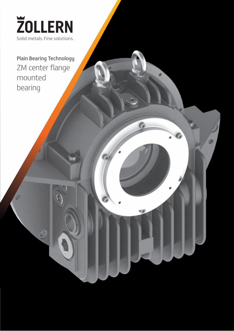
Plain Bearing Technology
ZM center fl angemountedbearing

The ZOLLERN Group ZOLLERN is one of the pioneers of the metal industry. 3,000 employees at 14 production locations and seven subsidiaries in Europe, North and South America and Asia develop, manufacture and supervise a range of innovative metal products. ZOLLERN supplies sophisticated solutions for diverse applications through its business units drive technology, plain bearing technology, foundry technology, mechanical engineering elements and steel profiles.
Content Side
Description of the ZM design 3
Radial bore profile selection 4
Oil flow 5
Radial and axial loads 5
ZM bearing dimensions 6
ZM 28 bearing dimensions 8
Dimensions of shaft 10
Types and dimensions of seals 12
Bearing types and designations 14
Checklist 15
Description of the ZM design
The ZOLLERN type ZM horizontal bearing is designed according to DIN 31 694 norm specifications for a wide range of heavy duty applications (electrical machines, turbines and test rigs). The modular system applies to the different types of bearings (pedestal, end flange and center flange), i.e. it is always possible to combine different modules of this system. Thus, assembly is simple and mistakes due to the positioning of screws and pins are avoided during installation, commissioning and maintenance procedures.
HousingThe bearing housings are finned, and are manufac-tured from gray cast iron EN-GJL-300 (GG 30), which combines a better heat dissipation with high strength. Upon request, they can also be supplied in nodular cast iron. The spherical seat in the housing ensures easy alignment during assembly and the loads are evenly distributed into the lower part of the housing. Therefore these bearings are designed for highest stress applications. Thread holes for monitoring the temperature, for oil inlet and outlet, as well as for oil level, are provided on both sides of the housing as standard. The housing comes with an oil sight glass on one side. The opposite side is supplied plugged and may be used as an oil outlet. If needed, their positions can be exchanged by reversing these parts.
In the top half of the housing, a sight glass, which permits the loose oil ring to be viewed, and a plugged manual oil feeder are provided. The basic design can be easily amended, if required, to incorporate water cooling tubes, oil sump heater, vibration detectors (angled at 45°), horizontal, vertical and axial vibration sensors and earthing devices. Upon request, thread holes can be provided in the ZF housing to meet all 541 and 546 requirements for API norms.
Bearing shells The shell is supplied in halves and spherically seated in the housing, ensuring easy self-alignment during assembly. The material is low carbon steel, lined with high tin-based white metal. This construction ensures an easy assembly and a long life cycle. Bearing shells with plain cylindrical bore and loose oil ring are used in most cases, but other shapes of bore are possible. When the specific load on start-up is too high, or for very slow-speed applications, a hydrostatic jacking system can be incorporated. Bearing shells can be provided with or without thrust faces.
Q-type shells have no thrust capability for non-locating bearings.
B-type shells with plain white metal lined shoulders with oil grooves are suitable for small, temporary thrust loads.
K-type shells have taper land faces for medium thrust loads and both directions of rotation.
D-type shells, with taper land faces suitable for only one direction of rotation, are capable of absorbing higher thrust loads.
A-type shells, for the highest loads, are equipped with thrust tilting pads.
Oil supply Fully self-contained lubrication is achieved by using a loose oil ring. Alternatively, where bearings are lubricated by an external oil circulation system, this loose oil ring can be used to permit an emergency shutdown without damage in case an oil system failure occurs. Z-bearings can be used for marine applications, where an oil ring guide assures proper lubrication even if extreme vessel motions occur.
02 // 03 Description of the ZM design
Machine seal Where negative or positive pressures occur near the internal floating seals ZM bearings should be used with an additional machine seal to avoid interference from inside the machine. This machine seal is fitted to the machine side of the bearing assembly, creating a chamber between the machine seal and the bearing seal. To equalize the pressure, the chamber is connected to atmosphere, which prevents oil leakage from the bearing into the machine enclosure.
Selection of oil It is recommended that any branded mineral oil which is inhibited against foaming, ageing and oxidation is used as lubricant. The viscosity is suggested by ZOLLERN if the customer doesn t have preferences.
Bearing calculation ZOLLERN uses a state of the art calculation program which can provide the following outputs.
• Minimum oil film thickness • Maximum hydrodynamic pressure • Maximum bearing temperature • Oil outlet temperature • Minimum permissible oil flow • Frictional power loss • Stiffness and damping coefficients
Electrical insulation To prevent stray currents conducted by the shaft, Z-bearings can be supplied electrically insulated as an option. In this case, the spherical seat of the housing is coated with a wear-resistant and temperature-re-sistant synthetic material. Upon request, a grounding wire is provided to short out this insulation, passing through a thread hole (M12x1.5) in the housing.
Sealing The seals are selected for the different operation conditions and environments and for the requested protection level. The standard arrangement is the floating labyrinth seal (IP 44) made of high heat resistant, fiber-reinforced synthetic material. Bearings for high oil throughput are equipped with adjustable rigid seals (IP 44) made of aluminum alloy. Both types of seals can be equipped with bolt-on baffles (IP 55) or dust flingers (IP 54) if the bearing is operating in a dusty or a wet environment, or if rotating parts (clutches, couplings, fans etc.) are fitted close to the bearing. Special seals offering higher protection, or pressurized seals etc., can be supplied for special applications upon request. An end cover is used when the end of the shaft is inside the bearing housing.
Temperature control Provisions for the fitting of thermo sensors in the journal bush and oil sump are provided as standard. The type of sensor to be used depends on the type required by the readout equipment used (direct rea-ding, centralized control system, recording instrument, etc.). For bearings with high thrust loads, additional thermometers for the thrust part can be integrated.
Radial bore profile selectionThe radial bore profile type selection depends on several conditions. Among them we have the circumferential speed and the specific pressure. The following table should help in a preliminary selection.
// Type of radial bearing bore profile
Type of bore Circumferential speed U (m/s) Specifc load p (MPa)
C/L/F Cylindrical 0 … 30 0 … 4
Y Two-lobe 25 … 75 0 … 3
V Four-lobe 25 … 125 0 … 2
K Radial tilting pads 15 … 150 0 … 2
Oil flow
Size Diameter (mm) FRadial (N) - Type FAxial (N) - Type
L, C, F Y V/K B K D A
760 12.000 9.000 6.000 540 1.660 - -70 14.000 10.500 7.000 620 1.940 - -80 16.000 12.000 8.000 700 2.210 - -
980 19.648 14.736 9.824 860 3.430 4.940 9.68090 22.104 16.578 11.052 950 3.840 5.600 11.060
100 26.000 19.500 13.000 1.050 4.110 6.250 6.840
11100 32.560 24.420 16.280 1.190 4.740 7.320 11.060110 35.816 26.862 17.908 1.570 6.220 9.750 12.450125 42.500 31.875 21.250 1.460 5.730 9.190 7.520
14
125 52.700 39.525 26.350 1.940 7.650 11.760 23.860140 59.024 44.268 29.512 2.500 10.040 15.380 26.510160 68.096 51.072 34.048 2.050 7.970 12.730 16.590180 76.608 57.456 38.304 2.290 9.680 14.370 -
18
160 86.848 65.136 43.424 3.080 12.420 18.340 46.300180 97.704 73.278 48.852 3.860 15.580 23.490 51.440200 112.320 84.240 56.160 3.280 12.890 20.110 32.990225 126.360 94.770 63.180 3.650 15.570 22.750 -
22
200 134.800 101.100 67.400 4.500 17.410 27.210 79.170225 151.650 113.738 75.825 5.000 19.280 30.640 87.970250 175.700 131.775 87.850 5.500 22.280 34.170 65.470280 196.784 147.588 98.392 6.100 26.570 38.350 54.980300 210.840 158.130 105.420 4.300 18.230 26.320 -
28
250 213.200 159.900 106.600 6.500 26.770 39.280 123.710280 238.784 179.088 119.392 7.190 30.050 44.110 137.450300 262.200 196.650 131.100 7.660 31.720 47.330 105.560315 275.310 206.483 137.655 8.000 34.080 49.810 96.510335 292.790 219.593 146.395 8.470 30.860 53.030 74.820355 310.270 232.703 155.135 5.750 20.890 28.050 40.220
Radial and axial loads
Oil outlet thread
Oil outletDN
Maximum flow for oil ISO VG 32 and 46 at 40°C (l/min)
Maximum flow for oil ISO VG 68 and 100 at 40°C (l/min)
Oil outletthreads (using both oil outlets)
Maximum flow for oil ISO VG 32 and 46 at 40°C (l/min)
Maximum flow for oil ISO VG 68 and 100 at 40°C (l/min)
7 G 1" DN 25 7 5 2 x G 1" 14 109 G 1 ¼" DN 32 9 7 2 x G 1 ¼" 18 14
11 G 1 ¼“ DN 32 9 7 2 x G 1 ¼“ 18 1414 G 1 ½" DN 40 11 9 2 x G 1 ½" 22 1818 G 1 ½“ DN 40 11 9 2 x G 1 ½“ 22 1822 G 2" DN 50 18 16 2 x G 2" 36 3228 G 2 ½" DN 65 28 25 2 x G 2 ½" 56 50
Size
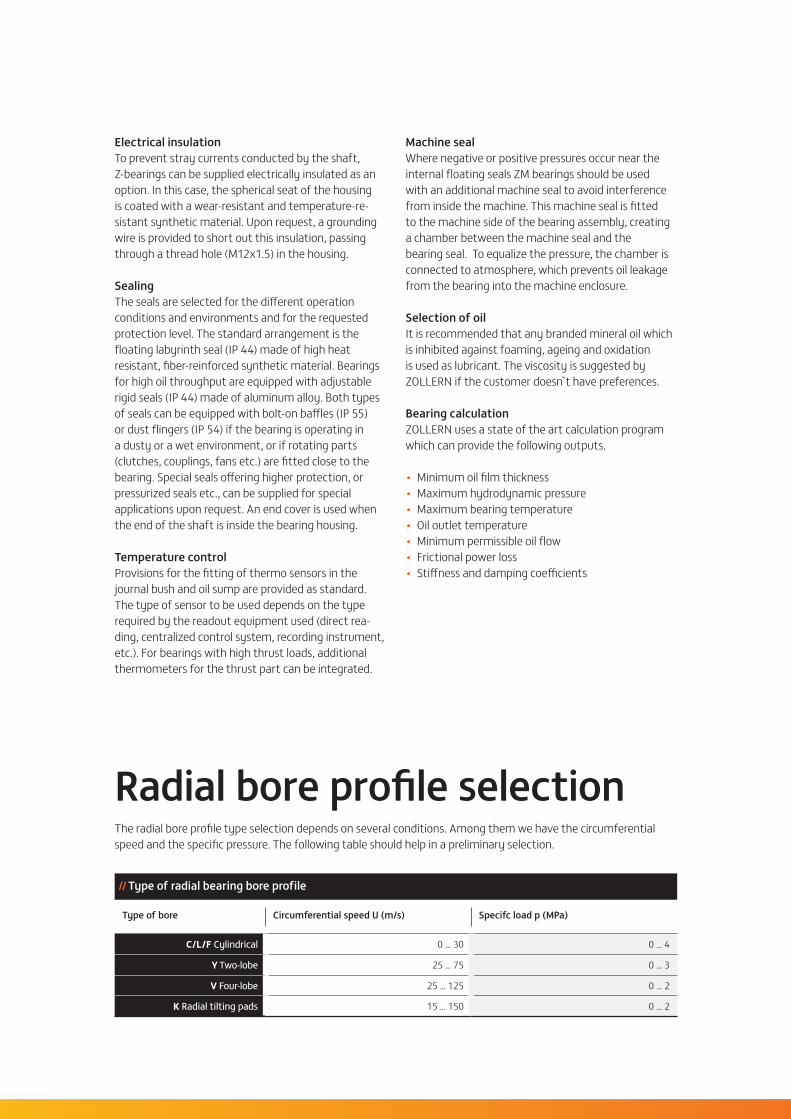
Z bearings are supplied without oil inlet or outlet flanges. Upon request, as additional items, ZOLLERN can supply these flanges according to DIN 2573 or ANSI B16.5 norms. Oil outlet flanges with weir are to be mounted with the weir horizontal at the bottom. The mark on the flange will then be visible in the center of the top side.
Please note: The loads presented within the table are values for a preliminary dimensioning of the bearing size. We recommend a specific bearing calculation to review the bearing dimensions selected.
04 // 05 Description of the ZM design / Radial bore profile selection / Oil flow / Radial and axial loads
Size D
(H7)B b1 b2 b3 b4 b5 b6 b7 b8 b9 b10 b11 b12 d1
nom. size seal
(optional)
d2 d3 d5 d7 d10 d11 d12 d13 d14 d15 d16 d18 d19 d20 (h8)
d21 d22 d23 d24 d25 d51 d52 e1 e2 e3 e4 e5 e6 e7 e8 e9 e10 h1 h2 l1 t ±5 dia.Ø K
760 50
60 101 79 20 15 22 10 5 86 59 115 25 60/7080/90 80 130 G
1/4 G1 6 x M6
66 86150 170 11 M6 250 265 300 325 235 350
90135 - - 24 6 24 26 45 15 70 48 125 30 175 98,5 206
93140 - 32 170 50 96 96 100 93
80 50 106 106 110 83
980 61,4
80 122 100 20 30 20 16 5 106 80 145 35 80/90100/110 100 150 G
3/8G1
1/46 x M6
86 110170 190 11 M6 285 300 375 400 270 425
110160
110 2027,5 12 27,5 35,5 60 20 85 67,5 142 45 212 114 250
104190
1458 2,290 61,4 96 120 120 120 20 104 16
100 65,0 106 130 130 125 16 104 20
11100 81,4
100 137 115 20 30 20 18 3 122 95 160 35 100/110125/140 125 180 G
3/8G1
1/46 x M6
108 135195 215 14 M6 340 355 450 475 320 500
135190
135 2025 15 35 42 70 22,5 100 70 167 55 250 132 300
130212
1687 4110 81,4 118 150 150 140 20 130 18
125 85,0 133 160 160 150 16 125 22
14
125 105,4
125 159,5 137,5 25 30 22,5 20 5 144 112,5 185 35 125/140160/180
160
230 G 3/8
G1 1/2
6 x M6
135 170
270 290 18 M6 400 425 530 560 380 600
170
250
165 25
30 27,5 45 55 85 27,5 125 85 200 70 300 167 355
157
280
18
150 6,3140 105,4 160 150 190 190 180 25 157 20160 106,4 160 170 200 200 195 20 135 24180 106,4 180 190 220 220 - - 123 -
18
160 135,7
160 179,5 157,5 25 30 17,5 25 6 165 132,5 210 40 160/180200/225
200
275 G 1/2
G1 1/2
8 x M8
172 215
320 340 22 M8 475 500 630 670 450 710
215270
210 31,5
35 30 60 68 105 30 155 80 240 80 355 195 425
189
335
18
230 9,5180 135,7 200 192 240 240 230 31,5 189 20200 140,4 200 212 250 250
300245 25 168 24
225 140,4 225 237 275 275 - - 143 -
22
200 168,5
200 219,5 197,5 30 30 17,5 30 8 200 167,5 245 40200/225250/280
300
250
340 G 3/4 G2 8 x
M8
214 265
380 400 26 M10 600 630 800 850 570 900
265335
265 40
40 35 70 83 135 40
175
100 310 100 450 251 530
242
425
18
425 22,5225 168,5 250 239 290 290 285 40 175 242 20250 175,7 250 264 315 315
390305 31,5 175 226 24
280 175,7 280 294 345 345 320 25 195 188 32300 175,7 300 310 345 345 - - 195 164 -
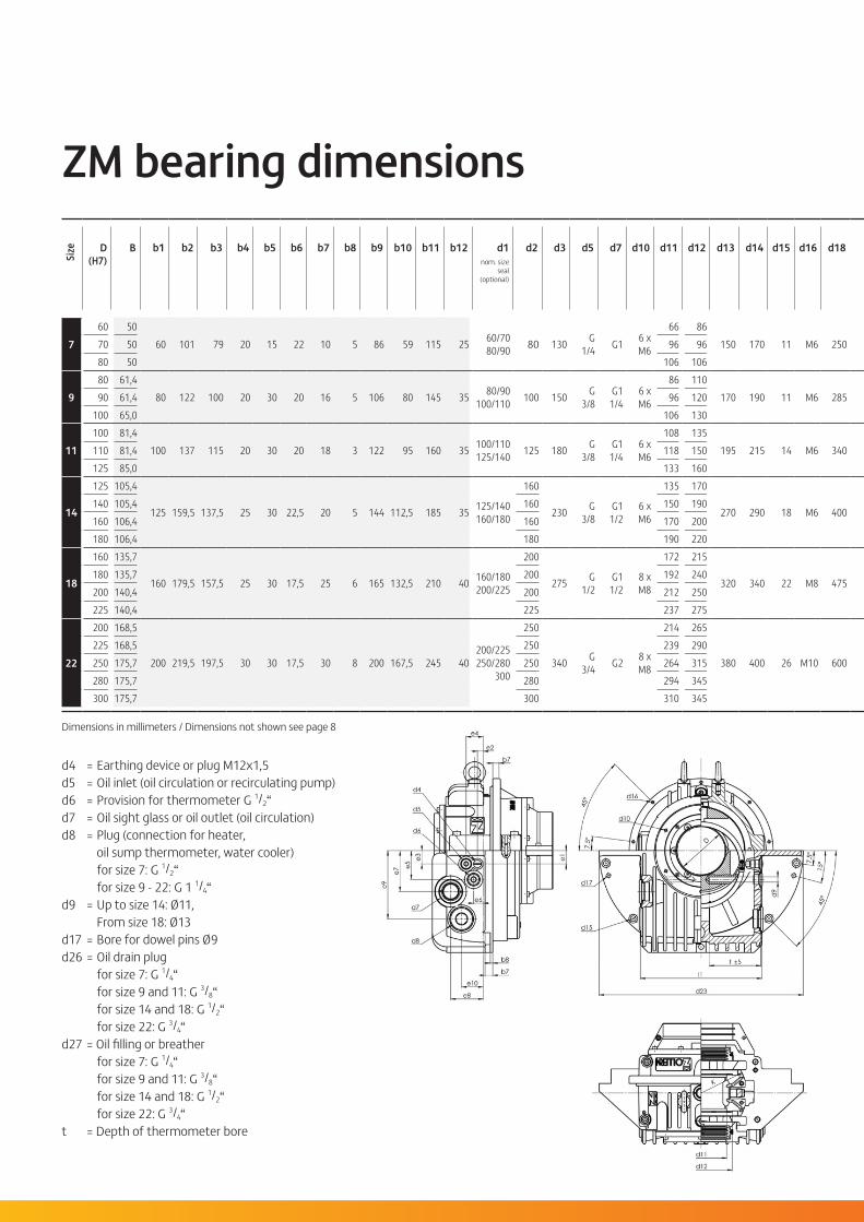
d4 = Earthing device or plug M12x1,5 d5 = Oil inlet (oil circulation or recirculating pump) d6 = Provision for thermometer G 1/2“ d7 = Oil sight glass or oil outlet (oil circulation) d8 = Plug (connection for heater, oil sump thermometer, water cooler) for size 7: G 1/2“ for size 9 - 22: G 1 1/4“ d9 = Up to size 14: Ø11, From size 18: Ø13 d17 = Bore for dowel pins Ø9 d26 = Oil drain plug for size 7: G 1/4“ for size 9 and 11: G 3/8“ for size 14 and 18: G 1/2“ for size 22: G 3/4“ d27 = Oil filling or breather for size 7: G 1/4“ for size 9 and 11: G 3/8“ for size 14 and 18: G 1/2“ for size 22: G 3/4“ t = Depth of thermometer bore
Dimensions in millimeters / Dimensions not shown see page 8
ZM bearing dimensions

Size D
(H7)B b1 b2 b3 b4 b5 b6 b7 b8 b9 b10 b11 b12 d1
nom. size seal
(optional)
d2 d3 d5 d7 d10 d11 d12 d13 d14 d15 d16 d18 d19 d20 (h8)
d21 d22 d23 d24 d25 d51 d52 e1 e2 e3 e4 e5 e6 e7 e8 e9 e10 h1 h2 l1 t ±5 dia.Ø K
760 50
60 101 79 20 15 22 10 5 86 59 115 25 60/7080/90 80 130 G
1/4 G1 6 x M6
66 86150 170 11 M6 250 265 300 325 235 350
90135 - - 24 6 24 26 45 15 70 48 125 30 175 98,5 206
93140 - 32 170 50 96 96 100 93
80 50 106 106 110 83
980 61,4
80 122 100 20 30 20 16 5 106 80 145 35 80/90100/110 100 150 G
3/8G1
1/46 x M6
86 110170 190 11 M6 285 300 375 400 270 425
110160
110 2027,5 12 27,5 35,5 60 20 85 67,5 142 45 212 114 250
104190
1458 2,290 61,4 96 120 120 120 20 104 16
100 65,0 106 130 130 125 16 104 20
11100 81,4
100 137 115 20 30 20 18 3 122 95 160 35 100/110125/140 125 180 G
3/8G1
1/46 x M6
108 135195 215 14 M6 340 355 450 475 320 500
135190
135 2025 15 35 42 70 22,5 100 70 167 55 250 132 300
130212
1687 4110 81,4 118 150 150 140 20 130 18
125 85,0 133 160 160 150 16 125 22
14
125 105,4
125 159,5 137,5 25 30 22,5 20 5 144 112,5 185 35 125/140160/180
160
230 G 3/8
G1 1/2
6 x M6
135 170
270 290 18 M6 400 425 530 560 380 600
170
250
165 25
30 27,5 45 55 85 27,5 125 85 200 70 300 167 355
157
280
18
150 6,3140 105,4 160 150 190 190 180 25 157 20160 106,4 160 170 200 200 195 20 135 24180 106,4 180 190 220 220 - - 123 -
18
160 135,7
160 179,5 157,5 25 30 17,5 25 6 165 132,5 210 40 160/180200/225
200
275 G 1/2
G1 1/2
8 x M8
172 215
320 340 22 M8 475 500 630 670 450 710
215270
210 31,5
35 30 60 68 105 30 155 80 240 80 355 195 425
189
335
18
230 9,5180 135,7 200 192 240 240 230 31,5 189 20200 140,4 200 212 250 250
300245 25 168 24
225 140,4 225 237 275 275 - - 143 -
22
200 168,5
200 219,5 197,5 30 30 17,5 30 8 200 167,5 245 40200/225250/280
300
250
340 G 3/4 G2 8 x
M8
214 265
380 400 26 M10 600 630 800 850 570 900
265335
265 40
40 35 70 83 135 40
175
100 310 100 450 251 530
242
425
18
425 22,5225 168,5 250 239 290 290 285 40 175 242 20250 175,7 250 264 315 315
390305 31,5 175 226 24
280 175,7 280 294 345 345 320 25 195 188 32300 175,7 300 310 345 345 - - 195 164 -
Thrust face type A
Drawings shown here are for reference only. Some fin details, for example, may vary from size to size.
ZD ti
lting
pad
spe
r sid
e
appr
. wei
ght (
kg)
appr
. oil
cont
ent (
l)
06 // 07 ZM bearing dimensions
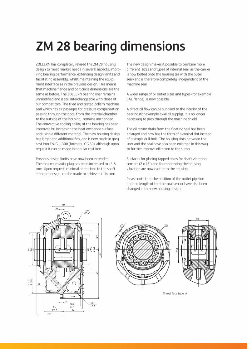
The new design makes it possible to combine more different sizes and types of internal seal, as the carrier is now bolted onto the housing (as with the outer seal) and is therefore completely independent of the machine seal.
A wider range of oil outlet sizes and types (for example SAE flange) is now possible.
A direct oil flow can be supplied to the interior of the bearing (for example axial oil supply). It is no longer necessary to pass through the machine shield.
The oil return drain from the floating seal has been enlarged and now has the form of a conical slot instead of a simple drill-hole. The housing slots between the liner and the seal have also been enlarged in this way to further improve oil return to the sump.
Surfaces for placing tapped holes for shaft vibration sensors (2 x 45°) and for monitoring the housing vibration are now cast onto the housing.
Please note that the position of the outlet pipeline and the length of the thermal sensor have also been changed in the new housing design.
ZOLLERN has completely revised the ZM 28 housing design to meet market needs in several aspects, impro-ving bearing performance, extending design limits and facilitating assembly, whilst maintaining the equip-ment interface as in the previous design. This means that machine flange and bolt circle dimensions are the same as before. The ZOLLERN bearing liner remains unmodified and is still interchangeable with those of our competitors. The tried and tested Zollern machine seal which has air passages for pressure compensation passing through the body from the internal chamber to the outside of the housing, remains unchanged. The convective cooling ability of the bearing has been improved by increasing the heat exchange surface and using a different material. The new housing design has larger and additional fins, and is now made in grey cast iron EN-GJL-300 (formerly GG 30), although upon request it can be made in nodular cast iron.
Previous design limits have now been extended. The maximum axial play has been increased to +/- 8 mm. Upon request, minimal alterations to the shaft standard design can be made to achieve +/- 14 mm.
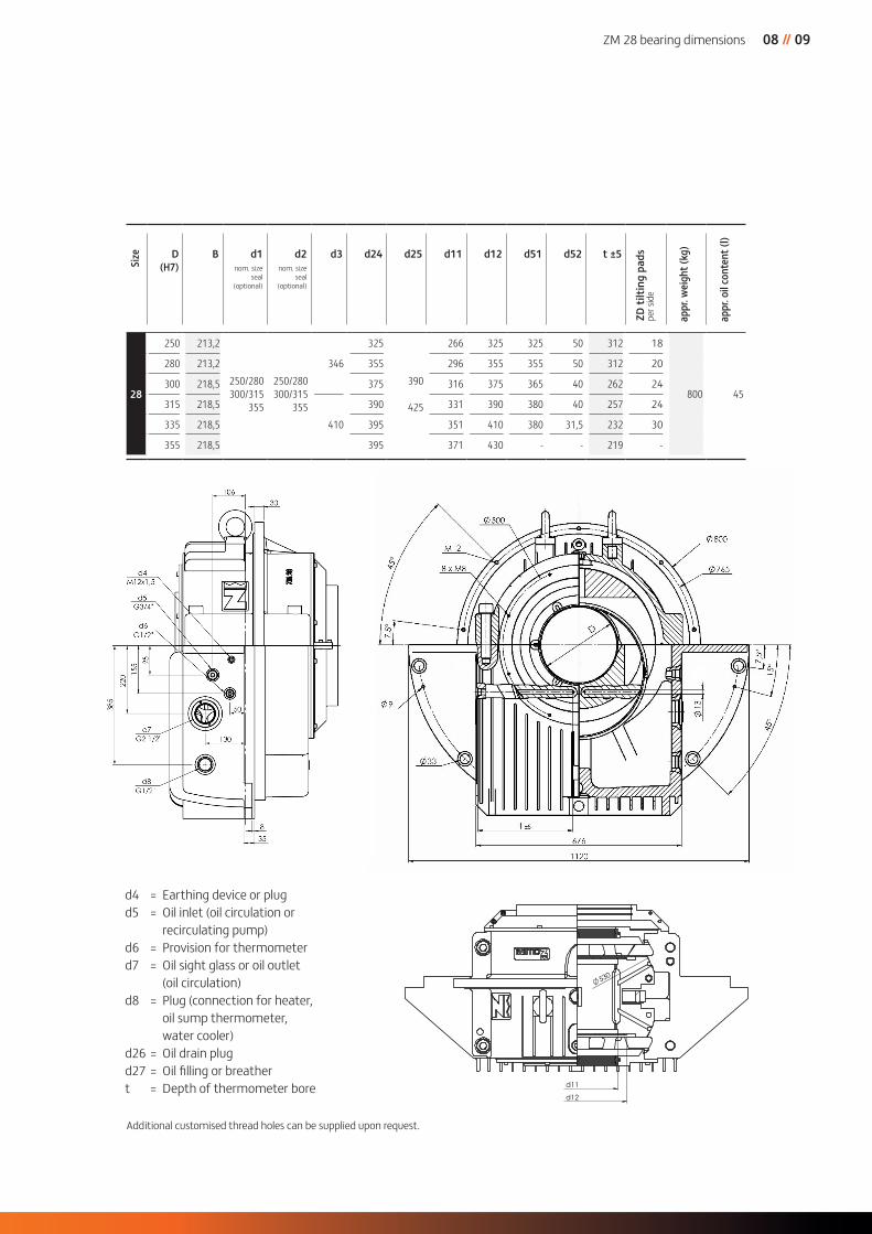
ZM 28 bearing dimensions
Thrust face type A
d52
d51
b1
ZD
Size D
(H7)B d1
nom. size seal
(optional)
d2nom. size
seal (optional)
d3 d24 d25 d11 d12 d51 d52 t ±5
28
250 213,2
250/280 300/315
355
250/280 300/315
355
346
325
390
425
266 325 325 50 312 18
800 45
280 213,2 355 296 355 355 50 312 20
300 218,5 375 316 375 365 40 262 24
315 218,5
410
390 331 390 380 40 257 24
335 218,5 395 351 410 380 31,5 232 30
355 218,5 395 371 430 - - 219 -
d4 = Earthing device or plugd5 = Oil inlet (oil circulation or
recirculating pump)d6 = Provision for thermometerd7 = Oil sight glass or oil outlet
(oil circulation) d8 = Plug (connection for heater,
oil sump thermometer, water cooler)
d26 = Oil drain plugd27 = Oil filling or breather t = Depth of thermometer bore
ZD ti
lting
pad
spe
r sid
e
appr
. wei
ght (
kg)
appr
. oil
cont
ent (
l)
Additional customised thread holes can be supplied upon request.
30 106
50 385
130
8 35
95
155
2
20
d6
d5
d7 G2 1/2"
d8 G1 1/4"
d4
A
A
530
d11
d12
d5 G 3/4"
d6 G 1/2"
d7 G 2 1/2"
d8 G 1 1/4"
d4
d1
d3
440
5
25
302
5
60
730
30 250
d2
d24
d
25
1000
10
60
50
30 205 257
245 212.5
35
300
d26 G3/4"
d27 G3/4"
M12x1,5
G1/2"
G3/4"
M12x1,5
08 // 09 ZM 28 bearing dimensions

Dimensions of shaft
Size D 1) b20 2)
(± 0,1)b21 3) b22 b23 4) b24 b25 d30 d31 (e8)
d32d33 d34 (e8) d35 5) (e8) d50 R1 6) R2 6) R3
760 86 60 / 70 / 80 / 90 70 9070 60,4 67 75 51,5 51,5 85,5 96 80 80 100 - 2 2 1,5
- / 64 / 74 / 8480 106 90 110
980
80,4 90 100 55 60 95110 80 / 90 / 100 / 110 90
100110 132
2,5 4 1,690 120 100 120 142- / 80 / 90 / 100100 130 110 130 143
11100
100,4 110 120 60 65 105135 100 / 110 / 125 / 140 110
125135 157
2,5 4 1,6110 150 125 150 162- / 100 / 110 / 125125 160 140 160 168
14
125
125,4 140 150 65 75 115
170125 / 140 / 160 / 180
140160
170 192
4 6 2,5140 190 160 190 207160 200
- / 125 / 140 / 160180
180200 217
180 220 200 220 -
18
160
160,4 180 190 65 75 120
215160 / 180 / 200 / 225
180200
215 244
4 6 2,5180 240 200 240 264200 250
- / 160 / 180 / 200225
225250 273
225 275 250 275 -
22
200
200,4 220 240 75 80 130
265200 / 225 / 250 / 280 / 300
225 - 265 308
6 6 4225 290 250 - 290 328250 315 280 250 315 339
- / 200 / 225 / 250 / 280280 345 310 280 345 348300 345 330 300 345 -
28
250
250,4 280 300 90 90 155
325250 / 280 / 300 / 315 / 335 / 355
280315
325 378
6 10 6
280 355 310 355 408300 375 330 375 408315 390
- / 250 / 280 / 300 / 315 / 335345
355390 423
335 410 365 395 414355 430 385 395 -
1) Limit dimensions of the shaft acc. DIN 31 698, form and positional tolerance and surfaces roughness acc. to DIN 31 699.
2) Standard thrust clearance is 0,5 mm. If reversible thrust loads or shock load occur, dimension b20 can be reduced by 0,2 mm. If a locating bearing (shell type B,K) is needed only for test runs, dimension b20 can be enlarged by 4 up to 6 mm.
3) If the non-locating bearing must allow larger motions (due to heat expansion or to large thrust clearances caused by the unit), dimension b21 can be enlarged.
4) The dimension b23 is valid for a bearing with a floating labyrinth seal.
5) The dia. d35 can be combined with every shell of dia. D within one size.
6) The radii R1 and R2 can be replaced by a plunge cut acc. to DIN 509.
For locating bearing shellZ…B (d30; α=10°) Z…K (d30; α=10°) Z…D (d30; α=10°) Z…A (d50; α=15°)
Machine side

Size D 1) b20 2)
(± 0,1)b21 3) b22 b23 4) b24 b25 d30 d31 (e8)
d32d33 d34 (e8) d35 5) (e8) d50 R1 6) R2 6) R3
760 86 60 / 70 / 80 / 90 70 9070 60,4 67 75 51,5 51,5 85,5 96 80 80 100 - 2 2 1,5
- / 64 / 74 / 8480 106 90 110
980
80,4 90 100 55 60 95110 80 / 90 / 100 / 110 90
100110 132
2,5 4 1,690 120 100 120 142- / 80 / 90 / 100100 130 110 130 143
11100
100,4 110 120 60 65 105135 100 / 110 / 125 / 140 110
125135 157
2,5 4 1,6110 150 125 150 162- / 100 / 110 / 125125 160 140 160 168
14
125
125,4 140 150 65 75 115
170125 / 140 / 160 / 180
140160
170 192
4 6 2,5140 190 160 190 207160 200
- / 125 / 140 / 160180
180200 217
180 220 200 220 -
18
160
160,4 180 190 65 75 120
215160 / 180 / 200 / 225
180200
215 244
4 6 2,5180 240 200 240 264200 250
- / 160 / 180 / 200225
225250 273
225 275 250 275 -
22
200
200,4 220 240 75 80 130
265200 / 225 / 250 / 280 / 300
225 - 265 308
6 6 4225 290 250 - 290 328250 315 280 250 315 339
- / 200 / 225 / 250 / 280280 345 310 280 345 348300 345 330 300 345 -
28
250
250,4 280 300 90 90 155
325250 / 280 / 300 / 315 / 335 / 355
280315
325 378
6 10 6
280 355 310 355 408300 375 330 375 408315 390
- / 250 / 280 / 300 / 315 / 335345
355390 423
335 410 365 395 414355 430 385 395 -
Drawing dimensions in millimeters
For non-locating bearing shellZ...Q
Machine side
10 // 11 Dimensions of shaft

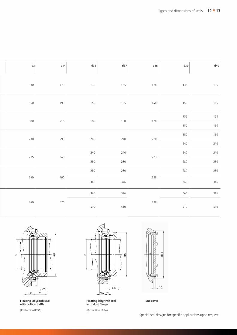
Types and dimensions of seals
Size D b26 b27 b28 b29 b30 b31 b32 d3 d14 d36 d37 d38 d39 d40
7
60
20 21 31 21 12 8 21,5 130 170 135 135 128 135 135708090
980
20 29 39 27 14 8 21,5 150 190 155 155 148 155 15590
100110
11
100
20 31 41 27 16 8 21,5 180 215 180 180 178155 155
110125
180 180140
14
125
20 33 43 27 18 821,6
230 290 240 240 228180 180
140160
26,5 240 240180
18
16025
36 46 27 21 8 26,5 275 340240 240
273240 240
180200
20 280 280 280 280225
22
200
30 39 49 27 24 8
26,5
340 400
280 280
338
280 280225250
31,5 346 346 346 346280300
28
250
35 43 53 27 27 10 31,5 440 525
346 346
438
346 346280300
410 410 410 410315335355
* Can be combined either with a bolt-on baffle (IP 55) or with a dust flinger (IP 54).
Floating labyrinth seal(Protection IP 44)
Rigid seal *(Protection IP 44)
Size D b26 b27 b28 b29 b30 b31 b32 d3 d14 d36 d37 d38 d39 d40
7
60
20 21 31 21 12 8 21,5 130 170 135 135 128 135 135708090
980
20 29 39 27 14 8 21,5 150 190 155 155 148 155 15590
100110
11
100
20 31 41 27 16 8 21,5 180 215 180 180 178155 155
110125
180 180140
14
125
20 33 43 27 18 821,6
230 290 240 240 228180 180
140160
26,5 240 240180
18
16025
36 46 27 21 8 26,5 275 340240 240
273240 240
180200
20 280 280 280 280225
22
200
30 39 49 27 24 8
26,5
340 400
280 280
338
280 280225250
31,5 346 346 346 346280300
28
250
35 43 53 27 27 10 31,5 440 525
346 346
438
346 346280300
410 410 410 410315335355
Special seal designs for specific applications upon request.
Floating labyrinth seal with bolt-on baffle
(Protection IP 55)
Floating labyrinth seal with dust flinger
(Protection IP 54)
End cover
12 // 13 Types and dimensions of seals
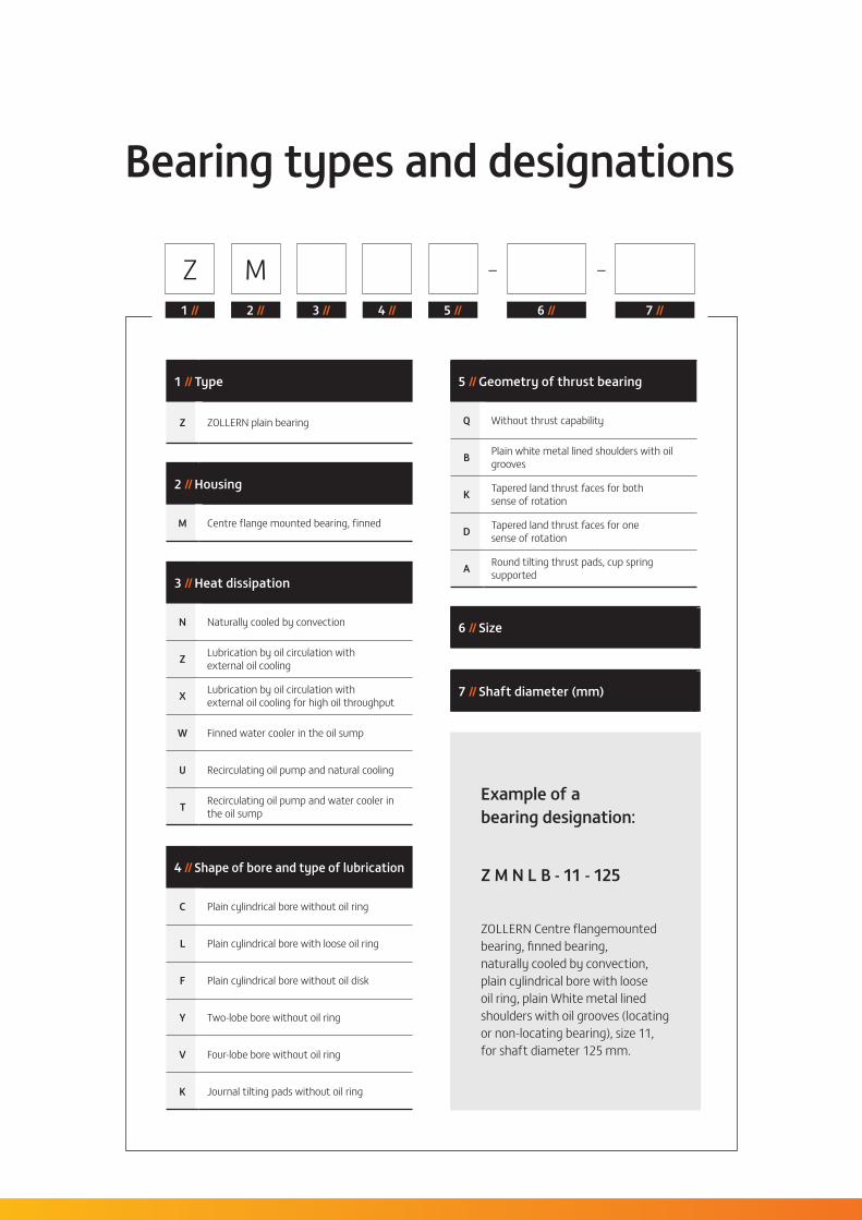
Bearing types and designations
1 // Type
Z ZOLLERN plain bearing
2 // Housing
M Centre flange mounted bearing, finned
3 // Heat dissipation
N Naturally cooled by convection
Z Lubrication by oil circulation withexternal oil cooling
X Lubrication by oil circulation withexternal oil cooling for high oil throughput
W Finned water cooler in the oil sump
U Recirculating oil pump and natural cooling
T Recirculating oil pump and water cooler in the oil sump
4 // Shape of bore and type of lubrication
C Plain cylindrical bore without oil ring
L Plain cylindrical bore with loose oil ring
F Plain cylindrical bore without oil disk
Y Two-lobe bore without oil ring
V Four-lobe bore without oil ring
K Journal tilting pads without oil ring
5 // Geometry of thrust bearing
Q Without thrust capability
B Plain white metal lined shoulders with oil grooves
K Tapered land thrust faces for bothsense of rotation
D Tapered land thrust faces for onesense of rotation
A Round tilting thrust pads, cup spring supported
6 // Size
7 // Shaft diameter (mm)
Example of abearing designation:
Z M N L B - 11 - 125
ZOLLERN Centre flangemounted bearing, finned bearing, naturally cooled by convection, plain cylindrical bore with loose oil ring, plain White metal lined shoulders with oil grooves (locating or non-locating bearing), size 11, for shaft diameter 125 mm.
Z M –
1 // 2 // 3 // 4 // 5 // 6 // 7 //
–
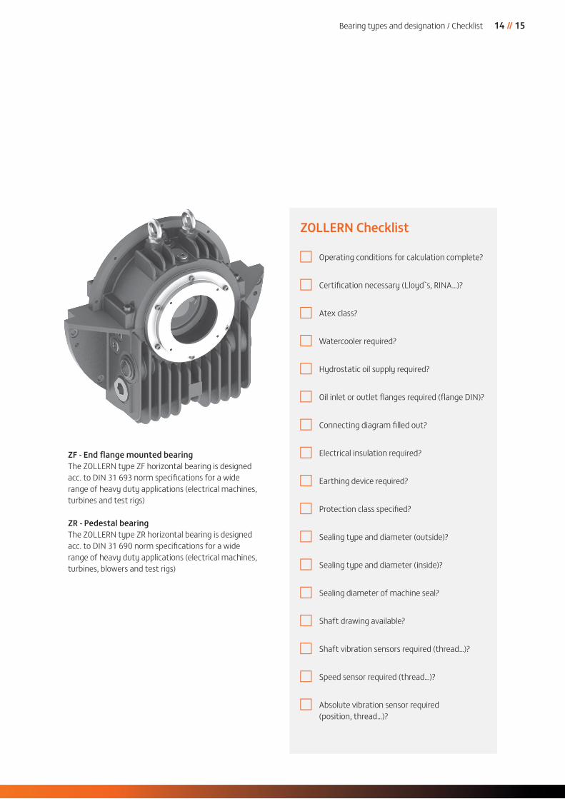
ZF - End fl ange mounted bearingThe ZOLLERN type ZF horizontal bearing is designed acc. to DIN 31 693 norm specifi cations for a wide range of heavy duty applications (electrical machines, turbines and test rigs)
ZR - Pedestal bearingThe ZOLLERN type ZR horizontal bearing is designed acc. to DIN 31 690 norm specifi cations for a wide range of heavy duty applications (electrical machines, turbines, blowers and test rigs)
ZOLLERN Checklist
Operating conditions for calculation complete?
Certifi cation necessary (Lloyd`s, RINA…)?
Atex class?
Watercooler required?
Hydrostatic oil supply required?
Oil inlet or outlet fl anges required (fl ange DIN)?
Connecting diagram fi lled out?
Electrical insulation required?
Earthing device required?
Protection class specifi ed?
Sealing type and diameter (outside)?
Sealing type and diameter (inside)?
Sealing diameter of machine seal?
Shaft drawing available?
Shaft vibration sensors required (thread…)?
Speed sensor required (thread…)?
Absolute vibration sensor required (position, thread…)?
14 // 15 Bearing types and designation / Checklist

Group headquarters
Subsidiaries & local offi ces
Plants
© Z
OLLE
RN I
04.18
I 00
4 I w
ww
.crea
ktiv
-wer
bung
.com
Er
rors
and
am
endm
ents
exc
epte
d. P
ictu
res a
nd ill
ustr
atio
ns si
mila
r.
ZOLLERN BHW Gleitlager GmbH & Co. KG
Rolandsweg 16-2037520 Osterode am HarzGermanyT +49 5522 3127-0 F +49 5522 [email protected]
www.zollern.com
ZOLLERN Transmissões Mecânicas LTDA
Av. Manoel Inácio Peixoto, 214736.771-000 CataguasesBrazilT +55 32 34 29 53 02F +55 32 34 29 53 [email protected]
All rights reserved to ZOLLERN GroupOur products are subject to constant technical alterations and developments and thus revisions may occur without prior or subsequent notice. This catalog is a preliminary version.