plane maker manual | x-planeand fly every day, helping you to keep up your stick-and-rudder and...
TRANSCRIPT

Plane Maker Manual
Author: Laminar Research 14 March 2019
For X-Plane Version 11.30

Table of Contents• Introduction to Plane Maker
• Licensing of Aircraft Created in Plane Maker • An Overview of the Plane Maker Workflow
• The Plane Maker Interface • Launching Plane Maker • Opening and Saving an Aircraft • Creating an Aircraft File
• Author Details and Basic Information • Working with the Views
• Special Views • Altering a Simple Aircraft
• Shaping the Body of an Aircraft • Fundamental Concepts
• The Reference Point • How Positions Are Set in Plane Maker
• Shaping the Fuselage • The Section Tab
• The Body Data Box • The Body Location Box • The Body Texture Box • The Cross-Sections Box
• The Top/Bottom Tab • The Front/Back Tab • Smoothing the Fuselage • Adding Other Bodies to the Fuselage
• Shaping the Wings • Setting the Basic Features • Adding Ailerons, Flaps, and Other Control Surfaces
• Specifying Ailerons, Elevators, and Other Surfaces • Specifying Flaps and Slats • Adding Control Surfaces to the Wings • Adding Body-Mounted Speedbrakes
• Customizing a Wing's Pieces (for Incidence, Size and Position) • Setting a Wing's Airfoils • Making a Wing Movable
• Setting Variable Wing Sweep • Setting Variable Wing Dihedral • Setting Variable Wing Incidence • Making a Wing Retractable
• Adding More Wing Sections • Shaping the Tail • Shaping the Landing Gear
• Setting the Gear's Type, Size, and Position • Finishing Retractable Gears
• Gear Warnings • Customizing Wheels and Steering • Designing Wheel Fairings and Skids
• Adding Other Surfaces and Bodies • Adding Engine Nacelles • Adding Engine Pylons
• Setting the Location of the Tow Hook, Winching Hooks, Boarding Door,

and Refueling Port • Working with the Aircraft's Systems
• Creating the Engines • Features Shared by All Engine Types
• Location • Throttle Settings • Critical Altitude and FADEC Characteristics • Boost Characteristics • Enging Spool Up • Specific Fuel Consumption
• Engines Capable of Zero-G Flight • Working with Engines That Turn Propellers
• Setting the Engine Details • Customizing the Propeller • Setting Up Solar Cells
• Working with Jet Engines • Working with Rocket Engines • Working with Twin- and Multi-Engine Aircraft
• Setting Up Electrical, Hydraulic, and Pressurization Systems • Configuring the Electrical System • Configuring the Hydraulics System • Configuring the Pressurization System
• Configuring the Avionics System • Configuring Instrument Performance Ranges, Display Limits, and
Colors • Setting V-Speeds and G Limits • Configuring the Autopilot
• Tuning Autopilot Roll • Roll Controls • Localizer Control
• Tuning Autopilot Pitch • Pitch Controls • Glideslope Controls
• Summary of Custom Autopilot Controls • Configuring GPS and FMS
• Configuring the Starter • Configuring the Fuel System
• Creating an Instrument Panel • Introduction to Panel Creation • Setting a Panel Background • Generic (Custom) Instruments
• Properties Common to All Generic Instruments • PNG file • Dataref/Command • Lighting Mode and Knob Number • Power Source & Bus Selectors • Clipping & Skewing • Visibility Filters
• Specific Generic Instruments • Annunciators (gen_annun) • Handles (gen_handle) • LEDs (gen_LED) • Needles (gen_needle) • Pies (gen_pie) • Pointers (gen_pointer) • Radio Frequencies (gen_radiofreq)

• Rheostats (gen_rheostat) • One-way rheostats (gen_rheostat_one_way) • Rolling Counters (gen_rolling) • Rotary knobs (gen_rotary) • Tapes (gen_tape) • Text (gen_text) • Triggers (gen_trigger)
• Sliders in the Panel • Modifying an Aircraft's Properties
• Setting the Identification Information • Customizing the Aircraft's Sounds
• Selecting and Configuring System Warning Sounds • Setting the View Properties • Configuring the Lights
• Configuring External Lights • Configuring Internal Lights
• Setting the Weight and Balance • Setting the Center of Gravity • Setting the Weights
• Modeling Additional Features of an Aircraft • Creating and Adding Weapons
• Building Weapons • Attaching Weapons
• Creating and Adding Slung Loads • Designing an Artifical Stability System
• Designing a Yaw Damper • Stabilizing Pitch
• Modifying the Appearance of an Aircraft • Creating a Basic Paint Job
• Fine-Tuning a Paint Job • Adding a Livery • Creating 3-D Objects for an Aircraft
• The 3-D Cockpit • The 3-D Panel • Attaching 3-D Objects • 3-D Object "Bouncers"
• Changing the Visibility of an Aircraft's Parts • Performing a Test Flight
• Testing with the Latest Flight Model • Distributing an Aircraft • Troubleshooting and How to File a Bug Report • Glossary of Terms
Last updated: 14 March 2019

About This Manual
This is version 11.30 of the manual to Plane Maker. The latest version of the manualwill always be available from the X - Plane Developer web site .
The best way to use this manual depends on what you need from it. If you’re already a master of Plane Maker, it probably makes sense to just keep this document around for reference. If instead you’re coming to this manual as a guide for a complete walkthrough to creating your first aircraft, it probably makes sense to read through in this order:
1. About This Manual (this page)
2. Introduction to Plane Maker
3. The Plane Maker Interface
4. Shaping the Body of an Aircraft
5. Working with the Aircraft’s Systems , Section “Creating the Engines”
6. Creating an Instrument Panel
7. Modifying an Aircraft’s Properties , Section “Setting the Weight and Balance”
8. Performing a Test Flight
Following the chapter Performing a Test Flight, your aircraft would be at least tested, and you could go back through the sections you skipped as necessary.
We recommend that users consult the Glossary of Terms found at the end of this manual for reference as needed.

Introduction to Plane MakerPlane Maker is a program bundled with X-Plane that lets users design their own aircraft. Using this software, nearly any aircraft imaginable can be built. Once all thephysical specifications of the airplane have been entered (e.g., weight, wing span, control deflections, engine power, airfoil sections, etc.), the X-Plane simulator will predict how that plane will fly in the real world; it will model the aircraft’s performance just like it does for X-Plane’s built-in aircraft.
Airplanes are saved in Plane Maker just as one would save a word processing document. These files are then opened and flown in the X-Plane simulator. Users can create a .zip file of all the components of the airplane and distribute that ZIP on the Internet for others to fly. Planes created by others can also be downloaded and used in the simulator. X-Plane.org’s “Download Manager” page is a good place both to upload and download these planes.
Note that information on how to add aircraft to X-Plane can be found in Chapter 7 ofthe X - Plane 9 (Desktop) manual , or in Chapter 4 of the X - Plane 11 (Desktop) manual.
Licensing of Aircraft Created in Plane Maker
You are free to do whatever you like with the aircraft you create.
You can, for instance, sell your aircraft files over the Internet, or modify other users’aircraft with their permission. If you choose to, you can share the files freely, even with users of the demo version of X-Plane. You can do whatever you like with the files.
One excellent use for Plane Maker is to create the airplane of your dreams, fly it in X-Plane, and then upload it to the Internet for others to fly. Even better, if a company has an exciting new airplane, they can build in Plane Maker, test fly it in X-Plane, and then put it on the company’s web site for customers or potential customers to download! Anyone that has X-Plane (or even the free demo) will be able to download the virtual version of the aircraft and fly it. This will serve two purposes. First, it will teach more people to fly the airplane, creating potential customers. Then, it will improve the currency of those that already fly it, creating safer customers. Carter Aviation, creators of the CarterCopter, have done this successfully on their website.
Of course, Plane Maker can also be used to model an aircraft that you already have and fly every day, helping you to keep up your stick-and-rudder and instrument skills.
An Overview of the Plane Maker Workflow
There are as many different ways to go about working in Plane Maker as there are aircraft designers. The following steps, though, serve as a good workflow sequence to start from when modeling in Plane Maker:
1. Decide on a design.
2. Create the fuselage, wings, and tail of the aircraft.
3. Create secondary objects, such as landing gears and engine nacelles.

4. Set up the systems and internal properties, including the engines, electrical systems, weight and balance, and viewpoints.
5. Set up any additional features of the aircraft, such as added weapons or special controls.
6. Create a 2-D instrument panel.
7. Test-fly the aircraft in X-Plane and fine-tune the features of the aircraft from steps 2–6 as needed.
8. Add textures, 3-D objects, extra liveries, etc.
Steps 2–8 above will be covered in this manual; for Step 1, you’re on your own!

The Plane Maker InterfaceRemember that definitions for any unfamiliar terms may be found in the Glossary. Helpful information has been built into every screen of Plane Maker as well. Hold themouse pointer over any of the boxes or buttons to bring up an explanation of the setting.
Launching Plane Maker
Plane Maker is found in the main X-Plane directory, which is located by default on the Desktop. Simply double click Plane-Maker.exe (Plane-Maker.app in Mac OS X) to start the program.
Note that in Windows 7 and Vista, there is a known issue with both X-Plane and Plane Maker relating to the “Aero” desktop effects. With Aero enabled, boxes and text may appear slightly shifted from where it should be. This problem does not occur on all Windows 7 installations. To correct it if it occurs, right click on the X-Plane.exe icon (or, alternatively, the shortcut you use to launch X-Plane) and click Properties. In the window that appears, go to the Compatibility tab and check the box labeled “Disable desktop composition”, shown in Figure 2.1. Repeat this for the Plane Maker icon, or the shortcut you use to launch Plane Maker.
Figure 2.1: Option to disable desktop composition
You have the option of editing dimensions in metric units. To change the unit of

measure, open the Viewpoint dialog from the Standard menu. In the General tab, click the check box labeled “edit in metric dimensions,” found on the right side of the cockpit information box. Note: Checking this will not alter the unit of measure for thrust or weight.
Opening and Saving an Aircraft
To open an aircraft in Plane Maker, click on the File menu and click Open, per Figure2.2. There, navigate to the folder containing the .acf file you want to modify, just like you would if you wanted to open the aircraft to fly in X-Plane. Select a specific paint job for the aircraft (known as a livery) by clicking one of the buttons in the bottom right section of the Open Aircraft screen, if applicable. Then, double click on the ACF, or click once and click the Open button.
To save any changes you have made to the aircraft file, open the File menu and click Save. Any changes you made to the aircraft will be reflected the next time you load the aircraft in X-Plane.
Figure 2.2: Clicking File –> Open
Creating an Aircraft File
To create a new aircraft project, open the File menu and click New. Plane Maker will create a new aircraft with nothing but a cylindrical fuselage. If you click File –> SaveAs from here, you can choose which folder to save the new aircraft in. Be sure to create the folder first in your file browser (Windows Explorer, Finder, etc.).
The standard place to save aircraft is in the Aircraft directory, located within the main X-Plane directory. For instance, a VTOL craft created for X-Plane 11 might be found in the following location:
X-Plane 11/Aircraft/My Custom Planes/VTOL/my new VTOL.acf
However, X-Plane doesn’t care where the aircraft is located—you could just as easilysave the project in the Scenery folder.
When you save your fuselage at this point in the creation process, Plane Maker will display a warning because critical information has not been entered yet. You may proceed through this manual in order by clicking the “Understood” button in the warning pop up after each save. If you would prefer to stop the warning messages, first set the “velocity never exceed (Vne)” as described in the section “Setting V-
Speeds and G Limits” below. Next you would need to set the weight by following thesection “Setting the Weight and Balance” and how the fuel is distributed in the tank(s) by following the directions in “Configuring the Fuel System.”
Author Details and Basic Information
The “Aircraft Author” window is available for users to input detailed information about themselves and their aircraft creations. You should begin any new aircraft by

filling in as many of the fields here as possible.
Figure 2.3: The available fields in the Author dialog
By filling out these fields, you’ll be able to search through your X-Plane 11 aircraft by name, manufacturer, category (general aviation, airliner, glider, etc.), design studio, and more.
In Plane Maker 11.10 you’ll be able to mark a plane as viable for user flight only, AI flight only, or both, with two new check boxes.
Working with the Views
Figure 2.4: The 3-D aircraft model in the main Plane Maker window

In the main Plane Maker window sits a 3-D model of the aircraft you’re working on. For instance, Figure 2.3 shows the 3-D model for X-Plane 11’s Stinson L–5 Sentinel.
You can move the whole aircraft model left, right, up, or down by using the arrow keys on the keyboard. Note that the axes are inverted; press the left arrow to move the model right, press the down arrow to move it up, and so on.
You can use the W, A, S, and D keys to spin and roll the 3-D model around its center. You can use the - and = keys to zoom out and in, respectively. Note that youcan zoom in and out or move the model faster by holding down the Shift key while pressing the up, down, left, right, -, or = keys.
Additionally, in most of the settings dialog boxes, a 3-D model of the aircraft is visible on the right side of the screen when the Plane Maker window itself is wide enough. For example, consider Figure 2.5; since the window is quite wide (wider than the standard size), the aircraft model is seen to the right.
Figure 2.5: This window is wide enough to see the 3-D model
Plane Maker can display either the regular, “skinned” view of the aircraft model (where the model looks as it would in X-Plane), or it can display a wireframe view showing the actual structure of the aircraft. To swap between these two views, press the spacebar. Figure 2.6 shows these two views side-by-side.
Figure 2.6: The skinned view of an aircraft, side-by-side with the wireframe view
The wireframe view can be especially useful for telling where exactly a piece of the aircraft is in relation to the rest of the body, and it is the only view in which the points representing the aircraft’s center of gravity, the pilot’s viewpoint, the jet engine locations, and other such features are visible. These are represented as large black dots in the wireframe.

Special Views
The Background menu has a number of special viewing angles that are useful for many designers. These are the Top, Bottom, Side, Front, and Back views, as seen below.
Figure 2.7: The five special viewing angles
Clicking one of these options in the menu will shift the 3-D model to the indicated perspective. For instance, the Top view gives a top-down view of the aircraft, the Side view gives a straight-on view of the craft’s port (left) side, and so on. One potential use for these views is to compare the aircraft model to an image of the real thing. Click the Background Bitmap button in the bottom left corner of the window to load an image to compare your model against.
For instance, if you had a top-down photo of the aircraft you were modeling and youwanted to see how closely your design matched it, you could click the Background Bitmap button, load that photo, and then select the Top view from the Background menu. This will display your Plane Maker model on top of the real aircraft’s photo, centered on the screen.
Altering a Simple Aircraft
To familiarize yourself with the workings of Plane Maker, it may be helpful to begin by tweaking a simple aircraft. The Boeing 777 from older versions of X-Plane is a good option. You can download a zip file of the aircraft here to follow along in the following examples.
Use the File menu to load the basic aircraft of your choice, then open the Standard menu and click Wings, as illustrated in Figure 2.8.
When the dialog box opens, click through the tabs labeled Wings 1–4 at the top of the dialog box. Different sections of the aircraft model’s wings will go black and flash subtly. (This will be easier to see if your window is wide enough to display a secondary aircraft model off to the right. Additionally, it will only work if the wings have not been made invisible, in the Invisible Parts dialog box of the Expert menu.) The section of wing that appears black is the section that the current tab controls. In the case of the 777, wing sections 1, 2, and 3 comprise the full wing.
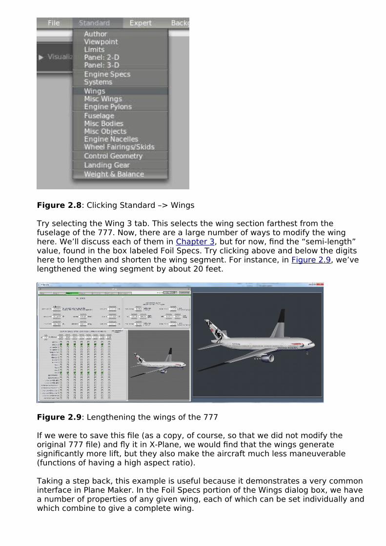
Figure 2.8: Clicking Standard –> Wings
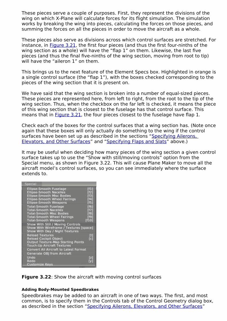
Try selecting the Wing 3 tab. This selects the wing section farthest from the fuselage of the 777. Now, there are a large number of ways to modify the wing here. We’ll discuss each of them in Chapter 3, but for now, find the “semi-length” value, found in the box labeled Foil Specs. Try clicking above and below the digits here to lengthen and shorten the wing segment. For instance, in Figure 2.9, we’ve lengthened the wing segment by about 20 feet.
Figure 2.9: Lengthening the wings of the 777
If we were to save this file (as a copy, of course, so that we did not modify the original 777 file) and fly it in X-Plane, we would find that the wings generate significantly more lift, but they also make the aircraft much less maneuverable (functions of having a high aspect ratio).
Taking a step back, this example is useful because it demonstrates a very common interface in Plane Maker. In the Foil Specs portion of the Wings dialog box, we have a number of properties of any given wing, each of which can be set individually and which combine to give a complete wing.

Note also that you can move the mouse over almost every input field in Plane Maker and get a description of what that field controls. Don’t know what the sweep field does? Mousing over the numbers in the input field reveals the following description:
The sweep is the angle that the wings are swept back from sticking straight out the side of the airplane. Wing sweep is used to allow high-speed travel (above Mach 0.7 or so), because the wing does not have to attack the air head-on.
Pretty informative, right? If you are ever unsure of what a parameter controls, mousing over it is a good way to get help.

Shaping the Body of an AircraftIn this chapter, we’ll look at the things that constitute the body of an aircraft, including the fuselage, tail, landing gear, wings, and airfoils. These represent the core of almost every aircraft design.
Note: You can change the unit of measure in the Default tab of the Viewpoint dialogbox, found under the Standard menu. Check the box “edit in metric dimensions” if you would like to edit the dimensions of your aircraft in meters.
Fundamental Concepts
A few ideas will come up over and over again throughout the creation of an aircraft body. The first is the concept of the reference point, and the second is the way in which positions in Plane Maker are set relative to the reference point. Understanding these two things ahead of time will make learning the specifics of creating the fuselage, wings, and other objects much faster.
The Reference Point
All objects (the fuselage, wings, etc.) in Plane Maker are placed relative to some arbitrary fixed point, called the reference point. This point is created simply throughuse. For instance, you might tell Plane Maker that your plane’s fuselage (and, in particular, the front tip of your plane’s fuselage) is located at the reference point—itis zero feet away from it, angled zero degrees away. Likewise, your wings might be located ten feet behind the reference point, angled a few degrees back.
On its own, this point doesn’t mean anything—it’s just some place on the aircraft that everything else gets its location in relation to. While the point could be anything, you should choose a point that makes sense to you. Some aircraft designers prefer to make their reference point the center of the fuselage, while others prefer to make it the tip of the nose.
How Positions Are Set in Plane Maker
As we have said, all locations in Plane Maker are defined relative to a fixed, arbitrary point, often the tip of the fuselage. However, there is more to defining the position of, for instance, a wing than to say that it is five feet behind the tip of the fuselage. How high above the tip of the fuselage is it? How far left or right?
This is where Plane Maker’s position settings come in. Figure 3.1 shows the three standard controls for an object’s position.
Figure 3.1: A standard position-setting group of parameters
The standard position parameters throughout Plane Maker are the longitudinal arm,

the lateral arm, and the vertical arm, as illustrated in Figure 3.2. Each measurementis in relation to the reference point.
Figure 3.2: The three axes used to position an object on the aircraft
The table below gives a reference for interpreting what the values in these positional controls mean. For instance, a positive value in the “vert arm” parameter indicates the object will move above the reference point by that many feet.
Parameter Positive value means… Negative value means…
Longitudinal arm Behind reference pt. Forward of reference pt.
Latidudinal arm Right of reference pt. Left of reference pt.
Vertical arm Above reference pt. Below reference pt.
Interpreting the position-setting values
Note that in cases where an object has lateral symmetry (that is, it is duplicated on both sides of the aircraft, as a wing section is), the guidelines in the table above apply to the object on the right (starboard) side of the aircraft. Likewise, the lateral arm value is reversed for the object on the left (port) side. Thus, a positive lateral arm value for a certain wing section means the right wing section will move right of the reference point, while the left wing section will move left of the reference point.

Shaping the Fuselage
To begin work on a fuselage, open the Standard menu and click Fuselage, as seen in Figure 3.3. There are three tabs across the top of the Fuselage dialog box, seen inFigure 3.4. In order, these are Section, Top/Bottom, and Front/Back.
Figure 3.3: Clicking Standard –> Fuselage
Figure 3.4: The three tabs across the top of the Fuselage dialog box
Each tab serves a different purpose. The Section tab displays a cross-section view ofthe fuselage, sliced into a number of pieces. The Top/Bottom tab shows three different perspectives of the points defined in the cross-section view, allowing you to see their relation in three-dimensional space. Finally, the Front/Back tab shows the same points of the fuselage from a head-on on perspective; this is like looking down the nose and tail, respectively, of a wireframe model of the aircraft.
In creating a fuselage, it makes sense to take the following approach (note that the parameters mentioned below are discussed in the following sections, which dive into each tab in depth):
1. Begin in the Section tab and set the number of stations (usually 20), the number of radii per side (usually 9), and the body radius.
2. Referencing whatever specifications you have for your fuselage (this may just be an image of it), set a rough outline of its shape in the cross-sections of the Section tab.
3. Still in the Section tab, move those rough cross-section shapes to the appropriate distances above or behind the reference point.

4. Go to the Top/Bottom tab and drag the points around in three dimensions, possibly with reference to a background image.
5. Alternate between the three tabs to fine-tune the shape.
The Section Tab
In the top-center of the Section tab’s window is a checkbox labeled “aircraft has fuselage.” By default, this box is checked; if the aircraft is a flying wing or another such oddity, it may need to be unchecked.
If you need to use the shape data from another file, you can use the button in the upper right of the window, labeled Import Aircraft Body. This will set the fuselage shape based on data from another aircraft.
You can save a description of the fuselage (or some other note about it) in the text box in the bottom right corner of the window, labeled “part description.”
Aside from these miscellaneous controls, the Section tab has four main divisions. These are the Body Data box, the Body Location box, the Body Texture box, and theCross-Sections box, described in the following sections.
The Body Data Box
Figure 3.5: The Body Data portion of the Section tab
The Body Data portion of the window, seen in Figure 3.5, controls the basic featuresof the fuselage. It is, effectively, your first stop when designing a new fuselage. The “number stations” field sets how many individual cross-sections Plane Maker will link together to form your aircraft’s body. In most cases, setting this at the maximum of 20 is not a bad idea, as each additional station will allow you greater control over the body’s shape. In any case, you will probably want to add 2 to the number of sections you had in mind to account for the fuselage’s two closed ends. For instance, if, when looking at the body, you saw 13 “real” divisions, you would input 15 stations here: 13 “real” sections, which meet at a point at the nose and tail, for a total of 15.
The “number of radii/side” value sets the number of points used in each half of the

cross-section. Unless your aircraft has a very simple shape to its body, you’ll probably want to use the maximum of 9; this will allow the smoothest curves possible on the body.
The “body radius” setting controls the width of the cross-section views in the bottom half of the window. For the greatest accuracy when placing the points that make up the body, this should be set to the actual maximum radius of the fuselage.You should, however, err on the side of setting this too high so that all your points are visible.
The final setting in the Body Data section of the window, labeled “body coeff of drag,” is the body’s coefficient of drag based on its frontal area. This determines theamount of drag generated by the fuselage. An average fuselage will have a coefficient of drag of 0.1, while a very sleek one will have a coefficient of 0.025.
The Body Location Box
The Body Location portion of the Fuselage dialog box controls the fuselage’s location. The three standard location controls (“long arm,” “lat arm,” and “vert arm”) specify the point in space of the front tip of the fuselage. See the section Fundamental Concepts above for an explanation of these three controls.
Figure 3.6: The Body Location controls
Since all measurements of location in Plane Maker are relative to the reference point, the fuselage position could be anything—the rest of the aircraft just has to bepositioned accordingly. Many aircraft designers, though, prefer the reference point to be the front tip of the aircraft. In this case, the fuselage’s location will be zero feet offset from the reference point.
In addition to the standard location controls, the Body Location box also contains directional controls. These are in the form of the heading, pitch, and roll offset parameters. The table below lists the interpretations of these values. For instance, setting a negative value in the heading offset will cause the fuselage to pivot to point left; when seen from above, the fuselage will pivot counterclockwise however many degrees are input here.
Parameter Positive value means… Negative value means…
Heading offset Pivots to point right (starboard) Pivots to point left (port)
Pitch offset Pivots to point up Pivots to point down
Roll offset Rolls right (to starboard) Rolls left (to port)
Interpreting the direction-setting values

In the vast majority of aircraft designs, it makes sense to think of the fuselage as the center of the aircraft, so these parameters will not be used.
The Body Texture Box
The Body Texture box is used for fine-tuning the painted texture on the aircraft (alternately known as a skin or a livery). For information on working with paint textures on the aircraft, see Modifying the Appearance of an Aircraft. For information on the parameters found in this box in particular, see the section of thatchapter titled Fine-Tuning a Paint Job.
The Cross-Sections Box
The Cross-Sections box shows slices of the aircraft’s fuselage. There is one slice of the fuselage for the number of stations set in the Body Data box, each slice in a gridded, white box, as seen in Figure 3.7. Each of these slices is composed of the number of points you specified in the “number radii/side” parameter in the Body Data box (see the section The Body Data Box above for more information on this). Since most designs warrant the maximum of nine radii per side, each of your slices will probably be composed of nine points.
Figure 3.7: The Cross-Sections box
When building your model, Plane Maker will stitch these slices together, so all the cross-sections together will form a complete aircraft body.
We’ve been referring to each of the gridded white boxes as containing a “slice” of the fuselage. In reality, they each contain a half-slice. The nine points (or however many radii/side you have set) seen here compose the right side of a slice; they will me mirrored by another nine points on the left side, for a total of eighteen (or so) points to compose a “full” slice.
Depending on the width of your screen, you may only see up to twelve of these half-slices at any one time; if you have set more “stations” (as described in the section “The Body Data Box” above), you can use the left and right arrows to cycle through the slices not seen. These arrows are highlighted in red boxes in Figure 3.8.

Figure 3.8: The left and right arrows highlighted
Let’s dissect each cross-section view—each “station”—in detail.
At the top of each station is an input field controlling how far behind the reference point this particular slice will be. For instance, in the example cross-section of Figure3.9, the slice is located 15.15 feet behind the reference point (indicated by the box labeled 1 in the image). Thus, in an aircraft whose reference point is the tip of the nose, this section would be about 15 feet from the nose. Of course, a cross-section could have a negative value here and be moved in front of the reference point.
Figure 3.9: A single cross-section view, or “station”

Note that Plane Maker will stitch your cross-sections together in the (left-to-right) order that they appear in this box—even if the distances from the reference point that you set in this box do not always increase from left to right. In this way, you could have a fuselage that overhangs itself, or curves inward in some way.
The gridded white box, labeled 2 in Figure 3.9, is the cross-section box itself. Click any point and drag it to reposition it and thus to reshape this slice of the fuselage. Double click on a point to lock its position, protecting it from being smoothed. (Note that smoothing operations are described in the section “Smoothing the Fuselage” below.)
Sometimes in the course of editing these cross-section points, it may be useful to zoom in and out or move the cross-sections around. You can zoom using the - and =keys, and you can move the sections using the left, right, up, and down arrow keys. This does not affect the model itself; it only changes the view of the model in editing. To return to the default level of zoom and the default positioning, simply click the Reset editing offsets button, located beneath the “Cross-Sections” box itself.
The left and right arrows beneath the cross-section box (labeled 3 in Figure 3.9) are used to copy a cross-section as a whole into the station to the left or right, respectively. This might be useful if you added a new station after working on the stations you already had. In this case, you would start with the farthest right of the stations you had previously worked on and press the right arrow. Then, you would move left and keep pressing the “copy to the right” button, stopping when you got to the place in the station order that you needed a new one.
Beneath those copy-left and copy-right buttons are general copy and paste buttons,labeled 4 in Figure 3.9. Press the Copy button beneath the cross-section you want to copy from, and press the Paste button beneath the cross-section you want to copy to.
Beneath the general copy and paste buttons are two fields for setting the left/right and up/down location of a given point in relation to the reference point. This allows for much greater accuracy in placing the individual radius points of a cross-section than can be achieved using a mouse. Click any point in the cross-section (labeled 2 in Figure 3.9) to see its distance both to the side and above or below the reference point. With the point selected, use the box labeled 5 in Figure 3.9 to change its distance to the side of the reference point. Positive values here indicate a point is on the right of the reference point. The box labeled 6 in Figure 3.9 sets the point’s distance above or below the reference point, with positive values indicating it is above the reference point.
Finally, at the bottom of each station is the Ellipse button, labeled 7 in Figure 3.9. Clicking this button will round the cross-section above into the closest-fitting, smoothly-curving ellipse. It will do so, however, without modifying any points that you have locked. To lock a point’s position, double click on it; rather than being represented in the cross-section view as a white-filled box, it will turn black.
The Top/Bottom Tab
The Top/Bottom tab of the Fuselage dialog box displays the fuselage’s cross-sectional “slices” stitched together in three different views; that is, it shows the top,side, and bottom views of the complete fuselage formed from the cross-sections. (Recall that these cross-sections may initially be laid out in the Section tab, described in the preceding section of the manual.)

To shape a station, simply click the radius points that make it up and drag them around. Just like in the Section tab, you can double click a point to lock it, preventing future smoothing operations from moving it on it.
The standard movement controls (the up, down, left, and right arrows, as well as the - and = keys for zooming) all operate as you would expect in this window, allowing you to zoom in or out and shift your view around.
Now, how do these three views (top, side, and bottom) fit together? It all starts with the side view—the left side view, in particular. The points that make up the left side are mirrored on the right, similar to the way the half-slices of the Section tab’s cross-section view are mirrored to form a complete slice. The middle, roughly horizontal line in the side view corresponds to the top- and bottommost lines in the top and bottom views.
The top and bottom views are mirrored in their upper and lower halves; dragging a point in the upper half of the top view will drag its corresponding point in the lower half of that view (in addition to dragging the same point in the side view). They are mirrored like this because the left side view itself is mirrored on the right; thus, the top view, for instance, shows the top half of both the left and right sides.
Figure 3.10: A situation where the “reset to vertical” buttons are useful
At the top of the window are two buttons, Reset this section to vertical and Reset all sections to vertical. Often in the course of editing the points of a fuselage, the points of a given section will get out of alignment purely by accident, due simply to the inaccuracy of using a mouse. That’s where these buttons come in.For instance, in the example fuselage in Figure 3.10, you might want to click the

Reset all sections to vertical button, thus lining up the points in each cross-section.
However, in some cases, it is desirable to not have all your sections vertically aligned. In this case, if you still wanted to align the out-of-whack section seen in Figure 3.10, you would need to first click one of the points in the section you wanted to align. Then, after you have effectively told Plane Maker which section youwant to modify, you would click the Reset this section to vertical button.
At the bottom of this window are buttons to load an image, clear it or lock during zoom. This can be quite useful for laying out your points properly. For instance, you could take two scale drawings of your aircraft (one to be used in both the top and bottom views and one to be used in the side view) and drag the radius points to match up with this image.
Figure 3.11: Using scale drawings to lay out the points of a fuselage
For instance, in Figure 3.11, we cut up two scale images to be the same size, with the center of the image corresponding to the center of the fuselage, and loaded the images into Plane Maker. From there, we simply dragged the outermost points (or uppermost points, as the case may be) to match the edges of the fuselage in the image. Following that, we dragged the inner points to match the known shape of the fuselage.

The Front/Back Tab
The Front/Back tab of the Fuselage dialog box contains two views of the cross-section, front and back. The front view shows the first twelve stations (if there are twelve stations to show) as though you were looking down the nose of a wireframe fuselage model. The back view, on the other hand, shows the last ten stations (again, if there are ten stations to show) as though you were standing at the tail looking down the wireframe model.
The standard movement controls (the up, down, left, and right arrows, as well as the - and = keys for zooming) all operate as you would expect in this window. Usingthe arrow keys, you can move the wire model over to view the whole fuselage, too, instead of just a half.
The radius points displayed in both these views operate just like the ones in the other two tabs. Simply click a point and drag it to change the fuselage shape there. You can also double click a point to prevent it from being changed in a future smoothing operation (described in the section “Smoothing the Fuselage” below).
The buttons Reset this section to vertical and Reset all sections to vertical are available in this tab as they are in the Top/Bottom tab. However, it may be wise to confine your use of them to the Top/Bottom tab, as you will not be able to see its effect in this view—the view is essentially without perspective, so a point that is far away looks the same as a much closer point with the same up/down and left/right position.
Smoothing the Fuselage
The most basic smoothing operation that can be performed on the fuselage is the smoothing of individual cross-sections to an elliptical shape. This is done using the Ellipse button in the Section tab of the Fuselage dialog, as described in the section “The Cross-Sections Box” above.
A much farther-reaching version of this smoothing operation can also be performed.Using the “Ellipse-Smooth Fuselage” option (or F1 key), located in the Special menu, will nudge all cross-sections of the fuselage toward the elliptical shape that would be obtained using the Ellipse button. Repeatedly using the “Ellipse-Smooth Fuselage” (or pressing F1) will have an effect identical to clicking the Ellipse buttonon all stations in the fuselage.
Adding Other Bodies to the Fuselage
Some aircraft have odd protrusions (such as a large fuel tank poking out from underthe fuselage) or even special physical objects attached to them. In this case, it may be best to model the fuselage itself as not having these things. Instead, you might model these things as separate “bodies” (physical objects) which intersect the fuselage. X-Plane doesn’t care whether the large protrusion on the underside of the aircraft is actually part of the fuselage or just another object touching the fuselage; it will model the aerodynamics the same way.
In this case, you would model the other things using the Miscellaneous Bodies dialog box, found in the Standard menu.
Each body created in this window is modeled almost identically to the fuselage; there is a Section, Top/Bottom, and Front/Back tab for each body, just as there is forthe fuselage. To add a new body, simply click a new tab from the top of the window

and check the box labeled “aircraft has this external fuel tank, float, or other external body,” as seen in Figure 3.12. You can add up to twenty miscellaneous bodies in this dialog box.
Figure 3.12: Checking the “aircraft has this … body” box
Finally, be aware of the Insert button, located between stations in the Cross-Sections box. Clicking this button will insert a new station between the stations on the left and right sides of the button. From there, you can of course use the Copy and Paste buttons to move your stations around. Note that you can only use the Insert button when you have fewer than 20 stations.
Shaping the Wings
Wings in Plane Maker are composed of individual wing sections. A very simple wing might be made up of a single wing section, while a very complex wing might be made up of four or more wing sections. Each wing section can have control surfacesadded, such as ailerons, elevators, or flaps. Furthermore, each wing section can have its cross-sectional shape (its airfoil) set independently of other sections.
Setting the Basic Features
To create and modify wing sections, open the Wings dialog box from the Standard menu.
The Wings dialog box houses a number of tabs whose contents all look identical. The only difference between them is that, whereas the tabs labeled “wing” and “horizontal stabilizer” control two identical wing sections mirrored on either side of the fuselage, the tabs labeled “vertical stabilizer” control only a single wing section.
When you click on any of the tabs, you will see three boxes in the window: the Foil Specs box, the texture fine-tuning box, and the Element Specs box.
The Foil Specs box controls all the basic properties of a wing section. All wing sections have the following properties:
• a semi-length, the length of the wing section from its root to its tip when measured 25% of the way back from the wing’s leading edge,
• a root chord length, the width of the wing section where it is closest to the fuselage,
• a tip chord length, the width of the wing section where it is farthest from the fuselage,

• a sweep angle, the angle backward or forward that the wing is pointing (when viewed from above),
• a dihedral angle, the upward or downward angle of the wing section relative to horizontal, and
• a location.
Figure 3.13 shows the foil specifications not including the location controls; for information on using the standard location controls, see the section “How Positions Are Set in Plane Maker” at the beginning of this chapter.
Figure 3.13: The foil specification parameters
In most cases, a wing is composed of more than one wing section. In this case, you could specify the location of the outer wing sections manually so that they meet up with the next sections closest to the fuselage. However, in the upper right corner of the dialog box is a drop-down menu labeled “snap to,” as seen in Figure 3.14. To snap a wing section to another one—that is, to have Plane Maker automatically align the root of the section you’re applying the snap to with the tip of the section you choose—simply click the drop down button and click on the wing section to snap to.
Figure 3.14: The “snap to” drop-down menu
To the right of the Foil Specs box is the texture box, used for fine-tuning the paintedtexture on the aircraft (alternately known as a skin or a livery). For information on working with paint textures on the aircraft, see Chapter 8, Modifying the Appearance of an Aircraft . For information on the parameters found in this box in particular, see the section of that chapter titled “Fine-Tuning a Paint Job.”
The Element Specs box in the bottom half of the window determines where ailerons,elevators, flaps, or other control surfaces go on the wing surface.
Adding Ailerons, Flaps, and Other Control Surfaces
To add control surfaces like elevators, rudders, ailerons, or flaps to a given wing section, you must tell Plane Maker where you want each control surface on the wingand you must define the control surfaces themselves. The first part is done using the Element Specs box found in the Wings dialog box, while the second part is donein the Control Geometry dialog box, launched from the Standard menu. The order inwhich you do these does not matter; do them in whatever order makes the most

sense to you.
For our purposes, we will start off in the Control Geometry dialog box. The only thing to be concerned with in this dialog box, at least until after the first test flight, is the Controls tab.
In the Controls tab, a number of possible control surfaces can be created, from ailerons to elevators to rudders to speedbrakes to flaps. Each of these works in a similar way. The left half of the window, in the box labeled Control Sizes, sets up ailerons, elevators, rudders, roll spoilers, drag rudders, and speedbrakes. The right half of the window, labeled Flap Specs, sets up flaps and slats only.
Specifying Ailerons, Elevators, and Other Surfaces
The left half of the Control Geometry’s “Controls” tab is labeled Control Sizes, and itis used for all control surfaces except the flaps and slats.
Figure 3.15 shows the parameters to specify a single control surface (namely, an aileron). There are four input fields here. On the far left is the control surface’s root-side width, as a decimal part of the chord length of the wing section it is placed on. Thus, if this root width were set at 0.50 and it were used in a wing whose root was 5feet wide, the control surface would have a width of 2.5 feet on the side closest to the fuselage.
Figure 3.15: A single, representative control surface specification
To the right of the root width is the tip width, also specified as a decimal part of the wing it is placed on. So, if the tip width were set at 0.1 and it were used on a wing whose tip was 10 feet wide, the control surface would have a width of 1 foot on the side farthest from the fuselage.
These two parameters, root and tip width, function identically on all the control surfaces available.
To the right of the two size parameters are the fields controlling how far the surface can move, measured in degrees. For instance, in the aileron of Figure 3.15 these are, from left to right, how far down the aileron can deflect and how far up it can deflect.
Specifications for ailerons, elevators, and rudders all follow this same pattern: parameters for the root and tip width, followed by parameters for the maximum deflections. The roll spoilers and drag rudder are exceptions to this pattern. They move one at a time, and they only move upward. For this reason, they have only one parameter for maximum deflection.
Additionally, the speedbrake may have two maximum deflections: one for normal, in-flight operation, and one for ground use. Unlike the other control surface types, speedbrakes don’t have to be mounted to a wing—they can also be mounted directly on the fuselage (or anywhere else, for that matter). For information on

doing this, see the section “Adding Body-Mounted Speedbrakes” below.
At the bottom of the Control Sizes box is the “control surface type” setting, which modifies how effective the surfaces are in X-Plane. Surfaces which are “corrugated with gaps” are least effective.
Specifying Flaps and Slats
The right half of the Control Geometry’s Controls tab is labeled Flap Specs, and it is used to set up the aircraft’s flaps and slats.
Let’s walk through the settings here.
Slats change the lift characteristics of a wing. They allow a higher angle of attack for the wing, resulting in a lower stall speed. Two slats can be set up for each aircraft. Using the parameters seen in Figure 3.16, you can set the type of slat—either true slats or Krueger flaps. (Note that Krueger flaps are not technically slats. They deploy by hinging forward from the wing instead of sliding from the top of the wing’s leading edge like slats do.)
Figure 3.16: The “slat type” and “increase in stall angle” settings
Next to the “slat type” control is the “increase in stall angle from leading edge device deployment” parameter, seen in Figure 3.16. Slats work by allowing the wingto go to a higher angle of attack without stalling—that is, without losing lift. Slats in the real world allow the wing to gain up to eight degrees of angle of attack without stalling.
Figure 3.17: The flap type and size settings
Like slats, flaps alter a wing’s lift characteristics. They allow the wing to generate a given amount of lift at a lower speed, resulting in the aircraft stalling at a lower speed. Two flaps can be set up for each aircraft. Using the parameters shown in Figure 3.17, you can set the type of flap, chosen from a large number of options. Each type of flap has unique lift, drag, and moment characteristics, as described in the dark gray box below the flap type setting. Four types of flaps available in X-Plane are illustrated in Figure 3.18.

Figure 3.18: Four types of flaps illustrated
To the right of the flap type setting are the two parameters controlling the size of the flaps. Just like when setting up ailerons, rudders, and elevators, you must specify the flap size on both the root side and the tip side. These are set as a decimal part of whatever wing section the flap is placed on.
Beneath the flap type and size settings are the parameters that control the aerodynamic coefficients for each flap, as seen in Figure 3.19. Plane Maker will automatically estimate the coefficients of lift (Cl), drag (Cd), and moment (Cm)
based on flap size and deflection, but these may be modified manually as well.

Figure 3.19: The flaps’ aerodynamic coefficients
If you find that the real aircraft slows down more than X-Plane predicts when flaps are lowered, you may want to increase the flaps’ drag coefficient, perhaps by about 0.01. If, on the other hand, you find that the real aircraft gives a lower stall speed than X-Plane predicts when the flaps are lowered, you may want to increase the flaps’ lift coefficient, perhaps by about 0.1. If you find that the real aircraft does not pitch up or down like it does in X-Plane when the flaps are lowered, you may need to increase or decrease the coefficient of moment. Decrease the flaps’ Cm by, say,
0.1 to pitch down more (or to pitch up less, as the case may be).
Beneath the flaps’ coefficients, you can set the deflection time as well as the detent(or stop-point) characteristics for both the flaps and slats, as seen in Figure 3.20. The flap deflection time is critical for getting proper pitch characteristics when the flaps are lowered.
Figure 3.20: The flap and slat detent characteristics and deflection time
Checking the box labeled “flaps are infinitely adjustable between detents” allows a pilot in X-Plane to hold the “flaps up” or “flaps down” button to select any flap setting, not just the ones at the detents. Even for aircraft with infinitely adjustable flaps, though, it is still useful to set the detents below, as they will be used in the maximum allowable flap deployment speeds. (Note that the max allowable speeds are set in the Viewpoint menu, as described in Chapter 4, in the section “Configuring Instrument Performance Ranges, Display Limits, and Colors”)
Beneath the “flaps are infinitely adjustable” checkbox is the flap deflection time parameter, as seen in Figure 3.20. This sets the amount of time in seconds that it

takes the flaps to go from fully retracted to fully extended.
Beneath the flap deflection time is the number of flap detents (as seen in Figure 3.20). A detent is a stopping place for the flaps, a middle-of-the-road between beingtotally retracted and totally extended. General aviation aircraft might have only oneor two stopping points, while airliners might have many more.
Finally, beneath the number of detents are the detent parameters themselves—one set of detent boxes for each flap and slat. Each box sets the flap/slat deflection in degrees at that detent. Note that there is one more box here than the number of detents you set above. This is to account for the “zeroth” detent, which in most aircraft will be a flap deflection of zero degrees.
For instance, in in Figure 3.20, three flap detents were set. Thus, there are four boxes for “flap 1,” four boxes for “slat 1,” and so on.
Adding Control Surfaces to the Wings
With the control surfaces (elevators, ailerons, rudders, flaps, etc.) all set up in the Control Geometry dialog box, as described in the sections above, it’s time to actually add those control surfaces to the wings. You will need to set the control surfaces individually for each wing section.
To do this, open the Wings dialog box from the Standard menu. In the bottom half of each wing’s tab is a box labeled Element Specs, as shown in Figure 3.21.
Figure 3.21: The Elements Specs box, specifying the control surfaces of a wing section
Highlighted in red in Figure 3.21 is the box controlling the number of pieces that thewing section will be broken into. The wing section will be divided into this many pieces of equal size.
These pieces serve a couple of purposes. First, they represent the divisions of the wing on which X-Plane will calculate forces for its flight simulation. The simulation works by breaking the wing into pieces, calculating the forces on those pieces, and summing the forces on all the pieces in order to move the aircraft as a whole.
These pieces also serve as divisions across which control surfaces are stretched. Forinstance, in Figure 3.21, the first four pieces (and thus the first four-ninths of the wing section as a whole) will have the “flap 1” on them. Likewise, the last five pieces (and thus the final five-ninths of the wing section, moving from root to tip) will have the “aileron 1” on them.
This brings us to the next feature of the Element Specs box. Highlighted in orange isa single control surface (the “flap 1”), with the boxes checked corresponding to the pieces of the wing section that it is present on.
We have said that the wing section is broken into a number of equal-sized pieces. These pieces are represented here, from left to right, from the root to the tip of the wing section. Thus, when the checkbox on the far left is checked, it means the pieceof this wing section that is closest to the fuselage has that control surface. This means that in Figure 3.21, the four pieces closest to the fuselage have flap 1.
Check each of the boxes for the control surfaces that a wing section has. (Note onceagain that these boxes will only actually do something to the wing if the control surfaces have been set up as described in the sections “Specifying Ailerons, Elevators, and Other Surfaces” and “Specifying Flaps and Slats” above.)
It may be useful when deciding how many pieces of the wing section a given controlsurface takes up to use the “Show with still/moving controls” option from the Special menu, as shown in Figure 3.22. This will cause Plane Maker to move all the aircraft model’s control surfaces, so you can see immediately where the surface extends to.
Figure 3.22: Show the aircraft with moving control surfaces
Adding Body-Mounted Speedbrakes
Speedbrakes may be added to an aircraft in one of two ways. The first, and most common, is to specify them in the Controls tab of the Control Geometry dialog box, as described in the section “Specifying Ailerons, Elevators, and Other Surfaces”

above. However, you can also add them directly to an aircraft’s body (its fuselage, wings, etc.), placing them using the standard Plane Maker position controls.
Body-mounted speedbrakes like these are created in the Speedbrakes tab of the Control Geometry dialog box. Once again, the Control Geometry dialog box is opened from the Standard menu.
Up to four body-mounted speedbrakes can be added to an aircraft using this tab; there is one box per speedbrake, as seen in Figure 3.23.
Figure 3.23: The four boxes for creating body-mounted speedbrakes
Since each speedbrake is created in the same way, we will look at the parameters for creating a single speedbrake.
Start by selecting the speedbrake’s type. The drop down box labeled 1 in Figure 3.24 selects a type of either “none” or “body mounted.” Any speedbrake box that you are not using should have a type of “none” set for it. Likewise, if you do intend to use a body-mounted speedbrake, set its type to “body mounted.”

Figure 3.24: The controls to create a single body-mounted speedbrake
After turning on any body-mounted speedbrakes you want to use, it makes sense tojump down to the geometry box, labeled 5 in Figure 3.24. Speedbrakes in X-Plane are 2-dimensional, composed of up to four points. Click away from any existing points to create a new one, and click a point and drag it to change the speedbrake’sgeometry. Note that the maximum width of the speedbrake geometry box here is determined by the “speedbrake max size” field.
After creating at least a rough model of the speedbrake’s shape, you can position it on the aircraft and set its extended and retracted angles.
To begin positioning a speedbrake, you can set the standard location controls, labeled 2 in Figure 3.24. These are presented here in longitudinal-lateral-vertical order, from left to right. For information on using these controls, see the section “How Positions Are Set in Plane Maker” at the beginning of this chapter.
Next is its “direction of extension,” located beneath the speedbrake type control and labeled 3 in Figure 3.24. A zero angle makes the speedbrake point straight up, while an 180 degrees makes it point down.
Beneath that are the speedbrake’s open and closed angles, labeled 4 in Figure 3.24.The parameter on the left is the angle of the speedbrake when it is retracted; the one on the right is its angle when extended. Positive values here will cause the speedbrake to hinge upward, while negative values cause it to hinge downward.
The final settings in each speedbrake’s box (labeled 6 in Figure 3.24) are related to its paint textures. Information on working with the paint is found in Chapter 8, in thesection “Creating a Basic Paint Job.”

Customizing a Wing’s Pieces (for Incidence, Size and Position)
In the Element Specs box—the same box used for applying control surfaces to wing pieces—is the piece incidence setting, highlighted in blue in Figure 3.21. This sets the upward angling (or incidence) of each piece, in degrees. This allows you to warpa wing section to point up or down.
Using the checkbox labeled “customize chords,” you can change the width of the wing section from its leading edge to its trailing edge (that is, its chord length) for each piece. Pieces are modified just like when adding a control surface to a piece; the boxes on the far left correspond to the portion of the wing section that is closestto the fuselage, while the boxes on the far right correspond to the portions farthest from the fuselage.
Figure 3.25: Customizing an aircraft’s chord size and position
Normally, Plane Maker calculates the chord length of each piece (again, the distance from its leading to its trailing edge) by interpolating between the root chord and the tip chord, which you set in this tab’s Foil Specs box. Using the “chord ratio” setting, though, you can modify the width of each piece. The Plane Maker-calculated value for the chord length is multiplied by the ratio you set here to get the actual width of this piece.
For instance, if Plane Maker saw that the chord length should be 5 feet at the centerof a given piece, and you used a chord ratio of 2, the center would end up with a 10-foot chord length. Likewise, if you had chosen a ratio of 0.5, it would end up witha chord length of 2.5 feet.
Finally, the “chord offset” setting, seen in Figure 3.25, determines how far forward or back a given piece gets shifted. Positive values will push the wing section behind the reference point, while negative values will push it forward of the reference point. This is specified as a ratio of the Plane Maker-calculated chord length. Thus, with a calculated chord length of 5 feet, and a chord offset of 0.5, a given piece will be pushed farther behind the reference point by 2.5 feet.
Use the above settings to customize the fine details of a wing section’s size and shape.

Setting a Wing’s Airfoils
Creating a wing in the standard Wings dialog box specifies only the wing’s size, location, and the direction it’s pointing—it does not specify what shape the wing has. Is it thin along the trailing edge and fat along the leading edge? Maybe it is fat along both edges, or maybe it is fat in the middle and thin at the edges. To tell Plane Maker just what (cross-sectional) shape the wing has, we need the Airfoil dialog box, which is launched from the Expert menu.
Each wing section can have four different airfoils set for it. These four airfoils come in two sets, one for high Reynolds numbers and one for low Reynolds numbers. Each set has one airfoil for the root and one for the tip. These airfoil shapes are thenblended together linearly in the portion between the root and tip, and the two sets (the low and high Reynolds number sets) are blended together between the Reynolds numbers.
The airfoil shapes themselves must be created using the separate Airfoil Maker application, which, like Plane Maker, is included in the X-Plane installation folder. X-Plane does not look at the shape of the wing and then decide how much lift, drag, etc. the foil will put out—X-Plane is not a computational fluid dynamics program. Instead, X-Plane uses pre-defined airfoils that list the performance of any airfoil (lift,drag, moment) to predict how the plane will fly with that foil. For information on using Airfoil Maker to create these airfoils with predefined performance, see the Airfoil Maker manual.
To apply an airfoil shape to a wing after the wing has been created, open the Expertmenu and click Airfoils. In the Airfoils dialog box, go to the Wings tab. Here, you canset two versions of both the root and the tip airfoil for each wing section. The foils on the left are for the root side of the section, and the ones on the right are for the tip side, as seen in Figure 3.26. Plane Maker will interpolate between the root and tip airfoil to create the shape of the middle of the wing section.
Figure 3.26: The root and tip airfoils
The top root-and-tip pair of foils in each wing’s box specifies the low Reynolds number version of the foil; the bottom pair specifies the high Reynolds number

version. Once again, X-Plane will interpolate between these two when your Reynolds number is between the high and low values.
The following two pages may be useful in determining what airfoils to use in your wing (assuming you’re modeling an aircraft that is already in production):
• The Incomplete Guide to Airfoil Usage
• StrategyWiki: Airfoils
To set an airfoil to be used on a particular wing, in a particular place (root or tip), and for a particular Reynolds number (high or low), click the gray box to the left of that position on that wing. A dialog box will appear for you to navigate to the airfoil file’s location. X-Plane’s default airfoils are found in the “X-Plane 11\Airfoils” directory.
Making a Wing Movable
Just like in the real world, wings in X-Plane do not have to be static. They can be swept forward or back, they can be angled up or down, and they can even be retracted.
Figure 3.27: The parameters to make a wing movable in the Airfoils dialog box
In the Airfoils dialog box (launched from the Expert menu), each wing has a group offour checkboxes, as seen in Figure 3.27.
Setting Variable Wing Sweep
Checking the first box in Figure 3.27, labeled “variable sweep,” will allow you to set the maximum wing sweep in degrees. Positive values here will allow the wing to angle further behind the reference point, while negative values will allow it to angle forward of the reference point. This variable sweep is illustrated in Figure 3.28.

Figure 3.28: Variable wing sweep illustrated (thanks to Wikimedia Commons user SteelPillow for the image)
Wing sweep is measured in degrees of sweep along the 25% chord (that is, along the line 25% of the way behind the leading edge of the wing). Note that you set the maximum sweep here; the minimum sweep is set as the default wing sweep, found in the Wings dialog box (opened from the Standard menu).
Variable wing sweep is useful in aircraft that approach or exceed the speed of sound, but which must also perform well at low speeds. As your speed increases toward Mach 1, a wing that meets the air head-on generates more and more drag. Variable sweep wings are most popular in military aircraft (like the B–1 Lancer and the F–14 Tomcat).
To use a variable sweep in X-Plane, you can add a sweep control to the instrument panel. Alternatively, you could assign a button or key to the “vector sweep aft” and “vector sweep forward” controls in the Joystick and Equipment dialog box.
Setting Variable Wing Dihedral
Checking the box labeled “variable dihedral” in the Airfoils dialog box (seen in Figure 3.27) will allow you to change the angle of the wing above or below the horizontal plane in flight. This is illustrated in Figure 3.29.
Entering a positive value here corresponds to an angle upward from horizontal (like the wings in Figure 3.29). Likewise, entering a negative value will correspond to a downward angle. A relatively high dihedral angle will increase the “dihedral effect” on the wings—that is, the wings’ tendency to stabilize and level the aircraft in a roll.

Figure 3.29: Wing dihedral, the upward angle of the wings, illustrated (thanks to Wikimedia Commons user Steelpillow for the image)
Setting Variable Wing Incidence
Checking the box labeled “variable incidence” in the Airfoils dialog box (seen in Figure 3.27) will allow you to change the wing’s angle of attack in flight. This angle, known as the angle of incidence, is illustrated in Figure 3.30.
Enter the maximum incidence here, in degrees. Positive values correspond to an upward angle of the wing when viewing the aircraft from the side, while negative values correspond to a downward angle.
Figure 3.30: Variable wing incidence illustrated on a high-wing plane (thanks to Wikimedia Commons user Steelpillow for the image)
A small positive angle of incidence is used in most aircraft in order to keep the fuselage horizontal when the aircraft is cruising. Thus, changing the angle of incidence in flight will also change the angle of the fuselage as the aircraft flies.
Making a Wing Retractable
The final dynamic wing checkbox in the Airfoils menu is labeled “retractable” (as seen in Figure 3.27). Check this box, then set the maximum retraction as a ratio of the wing section’s semi length. For instance, if the wing section was 10 feet long and you set the max retraction ratio at 0.5, the section would retract up to 5 feet into the fuselage.
Adding More Wing Sections
In some cases, the four “regular” wing sections, two vertical stabilizer sections, and single horizontal stabilizer section found in the Wings dialog box are not enough to accurately model an aircraft’s wings. In this case, you can add more wing sections by launching the Misc Wings dialog box from the Standard menu.

Wing sections here are added and modified just like in the regular Wings dialog box,with one exception: wing sections are not mirrored across the body. Instead, when you need a section duplicated on each side of the craft, you’ll need to create the wing section as it should be on the right side of the craft, copy that section to a newmiscellaneous wing tab, and there click the radio button labeled “(LEFT wing)” found in the Foil Specs box, as shown in Figure 3.31.
Figure 3.31: The radio button to add a wing section on the left side of the aircraft
Shaping the Tail
A typical aircraft tail is made up of a horizontal stabilizer and a vertical stabilizer. With this in mind, there are two vertical stabilizer sections and a single horizontal stabilizer wing section available in the Wings dialog box (launched from the Standard menu). These wing sections are shaped just like a standard wing, as described in the previous section, “Shaping the Wings.”
If you need more wing sections than are present in the Wings dialog box, you can add more sections using the Misc Wings dialog box, as described in the section “Adding More Wing Sections” above.
Shaping the Landing Gear
The landing gear is created using the Landing Gear dialog box, which is opened from the Standard menu.
Setting the Gear’s Type, Size, and Position
Landing gears come in a variety of configurations, ranging from simple metal skids, to a single wheel, to groups of many wheels. Any landing gear needs to have its position on the aircraft specified, and if the gear is retractable, it must have a retracted position that is different from its extended position. The gear also must have a size—both its tire size and its strut length.
These properties of the gear are defined using the first tab of the Landing Gear dialog box, labeled Gear Loc (that is, gear location). In this tab, you can create up toten different gears. Each gear has a column dedicated to setting its properties; Figure 3.32 highlights a single gear’s column.

Figure 3.32: A single landing gear’s column
Let’s walk through the settings for each gear.
Note: If you are using a retractable gear, you will want to do two things before trying to specify the gear’s properties. First, check the box labeled “retracts” at the bottom of the column. Then, close the Landing Gear dialog box and click “Show withstill/moving controls,” found in the Special menu. This will animate the gear as you work on it, so you can see just how far it extends and retracts.
At the top of the Landing Gear dialog box’s Gear Loc tab is the gear type parameter.Click the drop-down button and select from a wide array of wheel (or skid) configurations. A lateral wheel configuration arranges the wheels side-by-side, whilea truck configuration arranges them in rows. A “long” wheel configuration arranges them one in front of another. Finally, note that any gears you will not be using should have a type of “none” selected.
Next, beneath the gear type parameter are the three standard positional controls. These are, in order, the longitudinal arm, the lateral arm, and the vertical arm. For information on using these position controls, see the “Fundamental Concepts”

section at the beginning of this chapter, which discusses the reference point and its use in determining locations on the aircraft.
Following the standard position controls are the parameters determining the gear’s angle when extended and retracted. There is a “gear extended” pair of parameters,and there is a “gear retracted” pair. Each of the angles measures the gear strut’s deviation in degrees from being perfectly vertical, lined up with the reference point.
In the case of the longitudinal angles, the parameters measure how far the gear is angled to the fore of the reference point. Thus, if the gear needed to angle toward the aft of the reference point, you would use a negative number here. Positive 90 degrees will angle the gear forward and perfectly horizontal, while negative 90 degrees will angle it backward and horizontal.
In the case of the lateral angles, the parameters measure how far the gear’s strut isangled to the right of the reference point. Thus, if the gear needed to angle to the left, you would use a negative number. Positive 90 degrees will angle the gear to the right to be horizontal.
Following the gear’s extended and retracted angles is the eagle-claw angle & leg length parameters, set side by side on the same line. Leg length sets the length of the strut, or the “leg” of the gear, when it is extended. (For many aircraft, the extended and retracted length will be the same; some, though, may compress the gear when retracting it.)
Next are the two parameters controlling the tire size. Each of the tires on a given gear must be the same size. The tire radius is the length from the outer edge to the center of the tire, when viewing the aircraft from the side. Don’t confuse this with the diameter, which is the length from one side to the other when crossing through the tire’s center. The tire semi-width is half the width of the tire, when viewing the aircraft head-on. In Figure 3.33, the tire radius is shown in red, while its semi width is shown in blue.
Figure 3.33: The tire radius (red) and semi width (blue); thanks to Wikimedia

Commons user Kozuch for the photo.
The next controls are for the amount the nosewheel or tailwheel of the aircraft can steer. Enter zero for wheels that do not steer at all. For aircraft with steering nosewheels, see the section “Customizing Wheels and Steering” below.
Next are the “retract axis” and “strut compress” controls (in left to right order, respectively). The first parameter sets the amount, in degrees, that the wheel rotates around its own axis when it is retracted. Note that its axis is effectively the gear’s strut. Positive numbers here correspond to a clockwise rotation when viewed from the aircraft’s underside.
The strut compression parameter sets the amount, in feet, that the strut collapses on itself when the gear is retracted. In some aircraft, like the F–4 Phantom II, the gear compresses on itself like this to save space.
Next, beneath the retract axis and strut compression parameters is the “cycle time.” This is the time, in seconds, that it takes for the gear to go from fully extended to fully retracted, and vice versa.
Finally, at the bottom of the dialog box are four checkboxes. The first, “brakes,” should be checked for any gear that is used for braking. The box below that toggles whether the gear is retractable or not. The top box on the right side of the group is for castors. Check this box if the wheel castors freely all the time. The final checkbox, labeled “gear has fairing,” should be checked if the wheels have a streamlined fairing (also known as a wheel pant or spat). These structures are used to reduce the drag the gear generates by presenting a streamlined surface for the air to interact with. For information on creating the fairings themselves, see the section later in this chapter titled “Designing Wheel Fairings and Skids.”
Using the parameters above, you can create a basic gear with wheels and a simple strut. If the gear is retractable, you will still need to set a few more of its properties, as described in the following section, “Finishing Retractable Gears.” To fine-tune a gear’s steering properties, see the section “Customizing Wheels and Steering” below.
Finishing Retractable Gears
When creating a retractable gear, you will need to specify a few properties in addition to the size, position, and type. Many of these are located in the Landing Gear dialog’s Gear Data tab.
In the top section, “Gear Retraction and Nosewheel Steering,” is the “gear can retract on ground” checkbox. With this unchecked, the aircraft will sense that the gear is bearing the weight of the craft when it is on the ground and will thus not allow you to retract the gear. This is useful for preventing damage to the aircraft. Check the box directly below for seaplanes which have no landing gear and must take off and land on the water.
At the bottom of the right side of the section is the “additional gear flatplate area.” When the gear is extended, X-Plane will automatically add drag based on the frontalarea of the struts, the wheels, and the doors in its flight model. However, any time agear door opens up to let a wheel out, it also opens the gear wells. These wells disrupt the airflow over the craft, so you should enter the frontal area of the inside of this well here so that X-Plane can calculate the drag generated by it.

Gear Warnings
If a landing gear is retractable, there will often be a speed above which it is not safeto have the gear extended (the maximum landing gear extended speed, Vle) and a
speed above which it is not safe to extend or retract the gear (the maximum landing gear operating speed, Vlo).
To have X-Plane prevent the gear from extending at speeds above these limits, even if the gear handle is lowered, open the Special Equipment dialog box from the Expert menu. There, in the Equipment Options section, check the first box on the left for “gear extend protect.”
Additional gear warnings can be configured in the Systems dialog, chosen from under the Standard menu. In the “Gear Warnings” box at the bottom of the screen, check the box in the far right column labeled “gear warning horn equipped” to haveX-Plane play a warning noise if you do not lower the landing gear when you reduce power. The warning will also sound when the value in “activate if speed below” is met. Once below the activation speed, the values in the throttle and flap fields will also trigger the warning sound.
Customizing Wheels and Steering
Using the preceding sections, you can build a landing gear with the right wheel configuration, the right position, and even the right retraction characteristics. What we haven’t touched on yet is the steering characteristics of the gear, as well as the properties of the wheels themselves.
There are two “nosewheel steering” parameters on the Gear Location tab. These control how far, in degrees, the wheels responsible for steering can deflect while going slowly.
Figure 3.34: The steering and nosewheel settings
If the aircraft does not use the typical nosewheel steering configuration and instead uses free caster wheels which are controlled using differential braking, set this parameter to zero. (Note that nosewheel steering is a general term for steering by moving the wheels—it applies to taildraggers that steer with the tail wheel also.)
Figure 3.35: The landing gear friction coefficients
Another important set of parameters impacting the aircraft’s ground steering is the landing gear’s coefficients of friction. These parameters, found in the bottom of the Gear Data tab, are shown in Figure 3.35. The rolling coefficient of friction (the box on the left) controls how much friction is produced by the weight of the airplane on the wheels when rolling on pavement. A value of 0.025 is typical, indicating that the

drag of the wheels on the pavement is 0.025 times the weight of the aircraft when rolling. X-Plane will modify this value automatically when rolling on grass strips or off a runway.
The maximum coefficient of friction, the box on the right in Figure 3.35, controls themaximum amount of friction that the tires can generate, both by braking and from side loads.
Figure 3.36: The wheel and tire geometry settings
The final gear parameters we will consider here are those controlling the wheel and tire geometry. Figure 3.36 shows these controls, which are found in the middle of the Gear Data tab. The “wheel lateral separation” specifies the distance between wheels in a side-by-side configuration. This is measured in half-tire widths, from onetire’s middle to the other’s. Thus, a lateral separation ratio of 2 here puts the tires touching each other side by side.
The corresponding “wheel longitudinal separation” parameter sets the distance between wheels in an inline configuration. This is measured in tire radii (the distance from the center of the tire to its edge), from one tire’s middle to the other’s. Thus, a ratio of 2 here puts the tires touching along their edges as they rotate.
Designing Wheel Fairings and Skids
For each of your gears created in the Gear Loc tab of the Landing Gear dialog box, you can choose to add a streamlined fairing. Sometimes known as a wheel pant or spat, a fairing is designed to reduce the drag generated by a landing gear by presenting a streamlined surface for the air to interact with.
Before actually designing your fairings, you must tell Plane Maker which gears have them. This is done using the checkboxes in the bottom of the Gear Loc tab, as described in the section “Setting the Gear’s Type, Size, and Position.”
With at least one fairing specified in the Landing Gear dialog box, open the Wheel Fairings/Skids dialog boxs from the Standard menu. Each fairing you specified has its own tab here at the top of the dialog box. With one possible fairing per gear, andten possible gears, that makes for a total of ten fairing tabs at the top of the dialog box.
Fairings are modeled just like the fuselage and the miscellaneous bodies; there is a Section, Top/Bottom, and Front/Back tab for each fairing. See the “Shaping the Fuselage” for information on using these tabs.

Adding Other Surfaces and Bodies
In the previous sections, we’ve talked about creating a fuselage, a tail, wings, and alanding gear. What about everything else?
Some extra bodies have their own special dialog boxes for modeling. These include engine pylons, engine nacelles, weapons, and slung loads. All other extra bodies, like external fuel tanks, get no such special dialog boxes; instead, they are modeledin the Miscellaneous Bodies dialog box, described in the section “Adding Other Bodies to the Fuselage.”
For information on adding weapons and slung loads to an aircraft, see the section “Creating and Adding Weapons” in Chapter 7.
For information on engine pylons and engine nacelles, read on to the following sections of the manual.
Adding Engine Nacelles
An engine in X-Plane is primarily a point from which thrust is generated: propellers are no more than spinning, thrust-producing blades, jet engines are no more than points from which thrust is produced, and so on. To create the body of the engine (like the tip of the propeller or the body of a jet engine), you must add an engine nacelle. Figure 3.41 shows the parts of a propeller and a jet engine which would be modeled as nacelles in Plane Maker. Like every surface in X-Plane, these nacelles will have both visual and aerodynamic consequences. Note that it only really makessense to create the nacelles after you have created the engines themselves, as described in the section “Creating the Engines” of Chapter 4.
The Engine Nacelles dialog box is used to model these bodies. Bodies here are created just like the fuselage and the miscellaneous bodies; for more information, see the sections “Shaping the Fuselage” and “Adding Other Bodies to the Fuselage”previously in this chapter.
Figure 3.37: Parts of the engines modeled as nacelles (thanks to Wikimedia Commons user Delatorre for the jet engine photo)
There are eight tabs at the top of this dialog box, corresponding to the maximum of

eight engines you can specify in the Engine Specs dialog box. For each engine you want to build a nacelle on, check the box at the top of the tab reading “aircraft has a nacelle over this engine,” as seen in Figure 3.38. This box cannot be checked for engines the aircraft does not have. For instance, if the aircraft has two engines, the third tab at the top of this dialog box cannot have its “aircraft has a nacelle over this engine” box checked.
Figure 3.38: The “aircraft has a nacelle over this engine” checkbox
Note that unlike in the creation of the fuselage and miscellaneous bodies, each station’s distance behind the reference point (found in each nacelle’s Section tab, above the white gridded box used to create the sections) are set relative to the engine itself-not relative to the aircraft’s reference point. This makes sense; the nacelles are attached to a particular engine, not to the aircraft as a whole.
Figure 3.39 shows a wireframe view of a nacelle, side-by-side with its skinned counterpart. Note the large black dot on the left side of the nacelle in the wireframeview. This is the position specified for the engine itself; it is the “center of thrust” for the engine. This point serves as the reference point for this nacelle.
Figure 3.39: An engine nacelle, seen both in wireframe and textured views
Adding Engine Pylons
Engine pylons—the hardpoints of an aircraft designed to have engines mounted to them—are modeled using the Engine Pylons dialog box, launched from the Standardmenu. (Note that it only really makes sense to create the pylons after you have created the engines themselves, as described in the section “Creating the Engines” of Chapter 4.)
Modeling a pylon is very similar to modeling a wing—a pylon just ends up being a short, stubby, oddly shaped wing, which might itself be attached to a real wing. In light of this, the controls found in the Engine Pylons dialog box are identical to thosein the Wings dialog box, with a couple exceptions. For information on using the standard wing controls, see the section “Shaping the Wings” above.

Figure 3.40: An Airbus A380’s engine pylon (thanks to Wikimedia Commons user David.Monniaux for the photo)
The most important thing to note is that unlike in the creation of a wing, each pylon is place with respect to the engine to which it is (assumedly) attached—it is not placed relative to the aircraft’s reference point. Since engines in Plane Maker are just points from which thrust is generated, this works well.
Up to two pylon designs can be created for each aircraft. To apply a pylon design to a certain engine, check the box corresponding to that engine at the top of that pylon’s tab, as seen in Figure 3.41. These engines are numbered as they are in the Engine Specs dialog box; the engine on the far left in the Engines 2 tab of that dialog box corresponds to the checkbox on the far left here, and so on.
Setting the Location of the Tow Hook, Winching Hooks, Boarding Door, and Refueling Port
A few miscellaneous features of the aircraft’s body are set up using the Viewpoint dialog box, launched from the Standard menu. In the Viewpoint dialog box’s Dock Ports tab, the position of the aircraft’s tow hook, winching hook, refueling port, and boarding door can be specified using standard position controls, as described in the “Fundamental Concepts” section at the beginning of this chapter.

Figure 3.41: The Dock Ports tab of the Viewpoint dialog box
The position of these features of the body will only be visible when using the wireframe view (toggled using the spacebar). There, they will be represented as large black dots, just like the point representing the aircraft’s center of gravity.
Note that both the winching hook and the tow hook must be centered laterally along the aircraft’s body, so they do not have a “lat arm” parameter.
In addition, you can set what ground service vehicles, such as food, baggage, or fuel trucks, will service the aircraft in this screen.
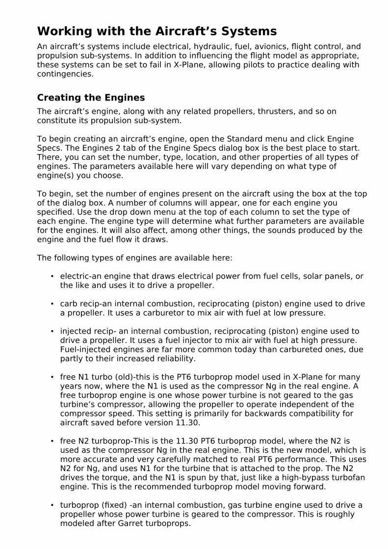
Working with the Aircraft’s SystemsAn aircraft’s systems include electrical, hydraulic, fuel, avionics, flight control, and propulsion sub-systems. In addition to influencing the flight model as appropriate, these systems can be set to fail in X-Plane, allowing pilots to practice dealing with contingencies.
Creating the Engines
The aircraft’s engine, along with any related propellers, thrusters, and so on constitute its propulsion sub-system.
To begin creating an aircraft’s engine, open the Standard menu and click Engine Specs. The Engines 2 tab of the Engine Specs dialog box is the best place to start. There, you can set the number, type, location, and other properties of all types of engines. The parameters available here will vary depending on what type of engine(s) you choose.
To begin, set the number of engines present on the aircraft using the box at the top of the dialog box. A number of columns will appear, one for each engine you specified. Use the drop down menu at the top of each column to set the type of each engine. The engine type will determine what further parameters are available for the engines. It will also affect, among other things, the sounds produced by the engine and the fuel flow it draws.
The following types of engines are available here:
• electric-an engine that draws electrical power from fuel cells, solar panels, or the like and uses it to drive a propeller.
• carb recip-an internal combustion, reciprocating (piston) engine used to drive a propeller. It uses a carburetor to mix air with fuel at low pressure.
• injected recip- an internal combustion, reciprocating (piston) engine used to drive a propeller. It uses a fuel injector to mix air with fuel at high pressure. Fuel-injected engines are far more common today than carbureted ones, due partly to their increased reliability.
• free N1 turbo (old)-this is the PT6 turboprop model used in X-Plane for many years now, where the N1 is used as the compressor Ng in the real engine. A free turboprop engine is one whose power turbine is not geared to the gas turbine’s compressor, allowing the propeller to operate independent of the compressor speed. This setting is primarily for backwards compatibility for aircraft saved before version 11.30.
• free N2 turboprop-This is the 11.30 PT6 turboprop model, where the N2 is used as the compressor Ng in the real engine. This is the new model, which is more accurate and very carefully matched to real PT6 performance. This uses N2 for Ng, and uses N1 for the turbine that is attached to the prop. The N2 drives the torque, and the N1 is spun by that, just like a high-bypass turbofan engine. This is the recommended turboprop model moving forward.
• turboprop (fixed) -an internal combustion, gas turbine engine used to drive a propeller whose power turbine is geared to the compressor. This is roughly modeled after Garret turboprops.

• jet 1 spool-this model always has the N1 spinning at a ratio to N2 that is a simple power curve. This setting is primarily for backwards compatibility for aircraft saved before version 11.30.
• jet 2 spool-this is the new jet engine model for X-Plane 11.30. The N2 is the power turbine in the hot section, spinning up and down as fuel is applied. Independently from that, the N1 is spun by the torque generated from N2, spinning the bypass fan. This is more accurate, since N2 can surge while N1 takes some time to respond, and N1 can windmill briskly even if N2 is shut down and barely spinning.
• rocket-a reaction engine which harnesses the acceleration of mass shooting out of its exhaust nozzle as propulsion.
The check box options “engine clutched” and “thrust vectors” are for helicopter engines and VETOLs respectively.
The following steps to set up an aircraft’s engines will depend in large part on whichengine type(s) you selected. There are, however, a few features that all engine types have in common.
Features Shared by All Engine Types
Regardless of the engine type selected in the Engines 2 tab, a few characteristics ofthe engine must be set. These include the engine’s location, its fuel consumption properties, and the altitudes at which it performs best.
Location
All engine types must have a position specified in the Engines 2 tab. This is done using the standard position controls (as described in the section “Fundamental Concepts” of Chapter 3), plus a vertical and side cant. Positive values for the vertical cant will cause the engine to point upward. Positive values for the side cant will cause the engine to angle right (clockwise) when viewing the aircraft from above.
All engine types also have the option to be vectored, using the checkbox beneath the side cant parameter.
Throttle Settings
In addition to their location, all engines must have a few characteristics of their throttle set. These are found the Engines 1 tab of the Engine Specs dialog box, in the General Engine Specs box there. Figure 4.1 shows the parameters relevant to most engine types.

Figure 4.1: Throttle settings in the Engine 1 tab’s General Engine Specs box
The first of these are max throttle with one engine failed, and max throttle with all engines running. These can, among other things, be used to fine-tune an engine’s performance to match measured performance in the real world. It is not uncommon to use a maximum throttle of, say, 0.80 in order to match an engine’s real-world performance, as manufacturers will often keep an engine within 75 or 80% of the nominal power to ensure safe, reliable performance. Allowing over 100% power alsomakes sense when leaving some reserve power for emergency operations. Max throttle with one engine failed sets the maximum throttle available when an engine failure has occurred.
Note that all engine specifications in Plane Maker are set with respect to full throttle. Thus, if you move the maximum throttle away from 1.00, the engine characteristics set throughout Plane Maker will not match the performance in X-Plane. This isn’t necessarily a problem, but you should keep it in mind.
Next are the low and high idle adjustment boxes. Plane Maker will automatically estimate where the engine idles, both in a low-idle situation and a high-idle one. Use this box to change the idle speed, as a ratio of the default Plane Maker estimate. Beneath these is the afterburner setting. Leave this at zero to allow the panel-switch to control the burner level.

Next is the “go to Beta Pitch below this throttle lever position” box. In engines that feature reverse thrust, the Beta range serves to maintain a constant RPM while varying the blade pitch, allowing finer control of the aircraft’s speed while on the ground. Use this parameter box to set the ratio of the joystick’s throttle at which to switch into Beta conditions. For instance, if you wanted to go to Beta when the joystick was at 25% of its throttle range, you would set this box to 0.25. The “beta available” box must also be checked in order to use this spec.
Beneath the “go to Beta” box is the “go to reverse thrust below this throttle lever position.” In engines capable of it, reverse thrust pushes the aircraft backward-quiteuseful when trying to land a large aircraft in a short distance. Just like the corresponding Beta parameter above, this is set as a ratio of the joystick’s throttle, and the corresponding check box to the right must be checked if the aircraft has this feature. Both Beta and reverse modes are virtually ubiquitous in both turboprops and jet engines. Likewise, they are uncommon in reciprocating engines.
The final field that can be set is “throttle available at max reverse lever position.” For engines that cannot be set in reverse, the maximum reverse throttle will be zero. Enter a number higher than 100% to leave some reserve for emergencies.
The final setting in the Engine 1 tab is the check box for “auto-set RPM and Throttle based on power level,” seen in the bottom of Figure 4.1. Some aircraft automatically set the prop RPM based on throttle position. To manually set the RPM with the power lever at idle, partway, and maximum, check this box and then adjustthe values in the three additional fields that appear.
Critical Altitude and FADEC Characteristics
Without modification, most engines put out less power the higher they go. The thinner air at high altitudes simply provides less oxygen to burn. Because of this, most aircraft have a critical altitude-a height above sea level above which they can no longer produce full power. At altitudes below this, full power is still available. Figure 4.2 shows the Critical Altitude box, found at the top of the Engine Specs dialog box’s Engines 1 tab. In that box, the “critical altitude” setting is specified in feet above mean sea level.
Figure 4.2: The Critical Altitude box in the Engines 1 tab of the Engine Specs dialogbox
Below the critical altitude parameter box is a check box for adding a FADEC, a Full Authority Digital Engine Control. A FADEC system is designed to control all aspects of the engine’s performance. One advantage to having a FADEC is that it can keep the engine from exceeding the maximum allowable thrust, as the checkbox in Figure 4.2 notes. (This can also be done by the automatic wastegate in a turbocharger-in this case, the same box should be checked.)
Boost Characteristics
All combustion engines (both jet and reciprocating) can have a boost applied to

them. This can come in two forms: an anti-detonant, or a nitrous oxide (N2O) boost.
When an anti-detonant is injected into an engine, the engine’s combustion chamberis cooled, increasing the density of the gases in the engine and increasing the engine’s compression ratio. It also serves to cool the engine, allowing it to run at a higher RPM than it otherwise would be able to. Nitrous oxide, on the other hand, decomposes quickly when it is injected into an engine. When it does, it increases the amount of oxygen available during combustion. Like an anti-detonant, the vaporization of N2O also cools the engine.
To tell Plane Maker that your aircraft has a boost, go to the Engine Specs dialog box’s Start/Spoolup tab. There, on the left side in the box labeled “Prop and Jet Boost,” are the two parameters for boost, shown in Figure 4.3.
Figure 4.3: The boost settings, found in the Start/Spoolup tab of the Engine Specs dialog box
X-Plane will not differentiate between the source of your boost, whether anti-detonant or nitrous oxide. Instead, it just needs to know how much of a boost your method gives. Set the “boost amount” box to the amount of boost you get from the engine, as a ratio to the normal, non-boosted engine’s performance. Thus, if your nitrous oxide system increased the power of your engine by 50%, you would set the“boost amount” parameter to 0.50.
Next, set the “boost capacity” box to the length of time, in seconds, that you can use your boost before it runs out.
To use the boost in X-Plane, simply push the throttle to its maximum; the boost will automatically kick in.
Engine Spool Up
A setting applicable to both propeller-driving and jet engines are the “compressor spool-up time” options found in the Start/Spoolup tab of the Engine Specs screen, highlighted in red boxes in Figure 4.4. This number is determined by the amount of inertia the engine has, and is applicable only to turbine engines, such as turbopropsand jets. It is a measure of how long it takes the low-pressure compressor (N1) to
speed up to its maximum when the throttle is brought instantly from idle to full. In X-Plane, the actual spool-up time will be affected by atmospheric conditions, the weight of the propeller (if applicable), and the time it takes the pilot to advance the throttle.

Figure 4.4: The spool-up time fields for turbine engines
Specific Fuel Consumption
After setting up the basic characteristics of a propeller or jet engine, you can set theengine’s specific fuel consumption. One box in the SFC/Sound tab (which is itself found in the Engine Specs dialog box) is labeled “Reciprocating or Turboprop Specific Fuel Consumption,” as seen in Figure 4.5. Another is labeled “Jet Engine Specific Fuel Consumption.” These boxes are identical except for the types of engines they affect.
Figure 4.5: The reciprocating or turboprop specific fuel consumption

Using these boxes, you can define the engines’ specific fuel consumption (SFC)-thatis, the amount of fuel burned per hour per engine horsepower. This should be set for two altitudes, one low and one high, and each altitude should have a half-power and full power SFC.
For propeller-driving engines, the measurement used here is the brake specific fuel consumption (BSFC), entered in the “Reciprocating or Turboprop” box. This is calculated as fuel flow divided by horsepower (as measured at the engine’s output shaft, before any transmission losses occur).
For jet engines, the thrust specific fuel consumption (TSFC) is used, and it is enteredin the “Jet Engine” box. TSFC is calculated as fuel flow divided by thrust.
In most cases, the “lo altitude for prop engines” (the low altitude at which you’ll specify the SFC) is zero feet above mean sea level. The “hi altitude for prop engines” may be your cruise altitude, but it doesn’t have to be. Both these controls are found in the left half of the Reciprocating or Turboprop SFC box.
In the right half of each box, the “half power SFC” for each altitude should be set to the specific fuel consumption in pounds of fuel per hour per horsepower of the engine when the engine is at half power. For instance, if a given engine burned 100 pounds of fuel per hour, and it had a 200 horsepower engine, it would burn 0.5 pounds per hour per horsepower. If that was the fuel consumption at your low altitude at half power, you would enter 0.500 in the “lo altitude half power SFC” box.
The “max power SFC” box works the same, but it specifies the fuel consumption at full power for each altitude.
Finally, in the bottom of the SFC box is the engine’s fuel flow at idle, as a ratio of the aircraft’s maximum fuel flow. If your aircraft used 0.1 times the fuel at idle as it does at full power, you would enter 0.10 here.
Note that specific fuel consumption in rocket engines is much simpler than in combustion engines; the SFC parameter found in the bottom right of the Engine Specs dialog box’s Engines 1 tab applies at all altitudes, at all power settings, for rockets. It defines the pounds of fuel burned per hour for each pound of the engine’s thrust. Note also that the specific fuel consumption is the inverse of the engine’s specific impulse (Isp), the number usually discussed in relation to a rocket’s
fuel consumption.
Engines Capable of Zero-G Flight
Some engines need to be capable of zero-G flight, or sustained flight at a pitch of 90degrees. This is most often seen in rockets and space ships. To model this in X-Plane, you must tell Plane Maker that the craft has an inverted fuel and oil system. To do so, open the Special Equipment dialog box from under the Expert menu and check the “inverted fuel and oil systems equipped” box in the third column, shown in Figure 4.6.

Figure 4.6: The “inverted fuel and oil systems equipped” check box
Working with Engines That Turn Propellers
Both of the reciprocating engines, as well as the turboprop, electric, and tip rocket engines all are used to turn propellers (or rotors, as the case may be). In this case, you must specify the number of propellers and their features using the Props 1 tab of the Engine Specs dialog box.
Near the top of the dialog box, right beneath the engine number and type settings, are the settings for the number and type of propellers. In nearly all cases, there will be one propeller per engine.
The following types of propellers are available in Plane Maker:
• fixed – a propeller whose angle of attack (or blade pitch) is fixed.
• manual pitch – a propeller whose pitch is adjusted manually by the pilot.
• constant speed – often referred to as a “constant RPM” or “variable pitch” propeller, this propeller will change the blades’ pitch in order to generate greater thrust while keeping a constant number of revolutions per minute (RPM).
• main rotor – a large, overhead rotor used in helicopters, held roughly parallel to the ground, which varies its thrust to maintain a constant RPM.
• tail rotor – a smaller rotor used in helicopters, held roughly perpendicular to the ground.
• VTOL cyclic – a large rotor in the style of a standard helicopter rotor. It varies its power in order to maintain constant RPM, but it can also change the direction of its thrust in order to facilitate vertical takeoff and landing.
• constant tip Mach – a propeller which adjusts its speed so that its tips always move at a constant Mach number, usually resulting in a more efficient flight than constant RPM propellers. The Mach number is chosen in Engine 1 tab if a prop of this type is selected.
• const ave AOA - the propeller rpm is automatically set by the prop governor tohold a desired angle of attack of the propeller. A blade is most efficient at a given angle of attack, so this increases or decreases pitch to set the right average angle of attack across the prop blade. The angle of attack (AOA) is chosen in Engine 1 tab if a prop of this type is selected on the airplane.
• lift fan – a downward-facing fan, such as is used in the F–35 Lightning II to facilitate vertical takeoff and landing.

Each propeller you specified will have its own column of settings, just like each engine does; the propeller settings will be integrated to the engine settings columns.
Figure 4.7: Setting the number of propeller blades and the direction in which they spin
Beneath the propeller number and type settings is the “number of blades” control, as seen in Figure 4.7. This number can be set independently for each propeller. Immediately to the right of the number of blades is the direction of spin, also in Figure 4.7. This is set either to clockwise (CW) or counterclockwise (CCW), as seen when looking at the aircraft from behind.
Below the blade direction setting are checkboxes, seen in Figure 4.7. The “prop clutched” and “prop ducted” boxes are used with autogyros and helicopters, respectively.
The checkbox labeled “prop ducted” is used with ducted fans-propellers mounted inside a cylindrical shroud. Ducted fans are also found in Fenestron tail rotors and lift fans (as in the F–35B). A very straightforward ducted fan is found in the Martin Jetpack, as in Figure 4.8.
Figure 4.8: The Martin Jetpack, with its ducted fans (thanks to Flickr user martinjetpack for the photo)
Continuing down the column on the Props 1 tab are the propeller settings, as seen in Figure 4.9.

Figure 4.9: The propeller specifications, found in the bottom of the Props 1 tab
The first of the propeller specifications, the prop radius, sets the distance in feet from the center of the propeller to the tip of one of its blades.
Beneath the prop radius are the settings for the propeller’s width. The “root chord” parameter (the left one of the pair) sets the width of the propeller in inches at its base, where it meets the aircraft body. The tip chord, likewise, is the width in inchesat the propeller’s tip, where it is farthest from its mounting place on the aircraft.
The “ellipse fraction” setting controls whether the propeller has a linear or elliptical planform, with 0.0 a perfect linear taper and 1.0 a perfect ellipse.
The fine and coarse pitch set the range, in degrees, over which the blade can change its angle of attack (pitch). This angle is measured at the propeller’s tip. Constant-RPM and manual pitch propellers, among other propeller types, vary their blade pitch to achieve a desired thrust at a constant rotational speed. Set the minimum pitch using the box on the left and the maximum using the one on the left. Typically, the minimum pitch is zero degrees, meaning the blades are “flat” against the wind they are moving into.
Next is the “design TAS at prop disc” setting. This is the speed of the air, in knots, that the propeller is optimized to have passing through it. For airplanes, this is approximately equal to the forward speed of the plane that you want to optimize forplus half the propwash. For helicopters, it should be the half the propwash only, since a helicopter’s forward speed is only a small component of the airflow into the rotor from above.

Beneath the pitch parameters is the “design propeller RPM” parameter. This sets the speed, in revolutions per minute, that the propeller is optimized for. “Design AOA at root and tip” will twist the blade to give the specified angle of attack at the two parameters filled in above it. Setting this to about 2 degrees is recommended.
The value set in “AOA root to tip spanwise power” will raise the prop span ratio for the interpolation between root and tip target angle of attack when setting the twist in the previous field. A value of 2.0, for example, will treat the 50% prop radius as the 25% radios in the interpolation, which will carry the root angle of attack target farther out into the mid-span.
The “max allowable prop pitch” is often set for manufacturing limits near the hub. The pitch might mathematically be able to go to 90º, but the prop may be limited to45º for manufacturing or structural reasons.
Based on the radius, design RPM, and design speed of the propeller, Plane Maker will automatically calculate an angle of attack for the length of the propeller. To modify this angle of attack, see the section “Customizing the Propeller” below.
The final setting for propellers is the engine-to-gear ratio, found at the bottom of the Engines 2 tab. This is the number of times the engine rotates for each rotation of the propeller. This is most commonly set to 1.000: for each rotation of the engine, the propeller rotates once.
Setting the Engine Details
After setting the engine’s location and the basic features of its propeller, you can set the details of its engine performance, such as its horsepower and the RPM for various modes.
Most of these details for a propeller-driving engine are set in the box labeled “Prop Engine Specs,” located in the Engines dialog box’s Engines 1 tab and shown in Figure 4.10. Other engine details, like the maximum throttle and the critical altitude, are common to all engine types, and are described in the section “FeaturesShared by All Engine Types” above.
Figure 4.10: The Prop Engine Specs box, found in the Engines 1 tab of the Engine Specs dialog box

In the upper left of this box is the engine’s maximum allowable power. This is the maximum horsepower output at sea level with standard atmosphere. If your aircrafthas an inlet, you can set how efficient it is using the “RAM-Inlet pressure recovery” box just below.
In the right column are the RPM values at which the engine redlines and idles. The redline RPM sets the maximum allowable rotations per minute for the engine, and the idle RPM sets the speed at which the engine turns when the throttle is set to zero. Reciprocating engines typically redline between 2,000 and 3,000 RPM.
The column has three additional boxes corresponding to three different engine RPM limits. The first box of the three, “top of green arc,” sets the maximum engine RPM that can be set using the prop control in X-Plane-the maximum RPM seen under normal operation. This should probably be close to the engine redline RPM set above.
Beneath the “top of green arc” box is the “bottom of green arc” parameter. This sets the minimum engine RPM that can be set using the prop control in X-Plane.
The final RPM limit here is the “minimum prop governor engine RPM.” This parameter sets the lowest RPM that can be obtained in X-Plane by pulling the prop control back. This does not take into account reverse, Beta, or feathered modes. (For information on setting these pitches, see the section “Customizing the Propeller” below.)
Two features of FADECs are specific to propeller-driving engines and can be selected in the left column of the Prop Engine Specs box. The first is “FADEC limits RPM on all propeller engines” which means it can keep the engine within its safe RPM limits. The option below it, “FADEC sets fuel-air ration on recip engines,” maintains the perfect fuel-to-air ratio, allowing for greater performance and cleaner exhaust.
The option just above the FADEC check boxes deals with helicopters only. If it has a governor, check the “all engines: have throttle-governor” box to automatically run the throttle up and down as needed to hold the operational RPM.
A few engine settings can also be set on the Start/Spoolup tap. In the second column, “engine-start fuel intro time” sets the time (in seconds) it takes fuel introduction to go from zero fuel flowing into the engines to the idle amount during the engine’s start process.
Customizing the Propeller
The propeller is initially created in the Engines 2 tab of the Engine Specs dialog box.As discussed in the section “Working with Engines That Turn Propellers” above, the Engines 2 tab specifies the propeller’s size, pitch, and design RPM. In many aircraft, though, there is much more to the propeller than that. To further customize the propeller, see the additional options in the Prop Engine Specs box of the Engines 1 tab.
In the bottom left corner are four check boxes that deal with general behavior of all propellers on an aircraft. The first two boxes determine if the propeller goes to its feathered pitch when the prop control is pulled back to minimum, or when the mixture control is at minimum, respectively. Check the third box to have all the propellers automatically feather to reduce drag after an engine failure. The final option in the column affects the engines, but is based on the propeller control;

check this to shut off fuel when the control is pulled to minimum.
The first specific characteristic of a propeller that can be set is the feathered pitch of the prop, as seen at the top of Figure 4.11. This sets the pitch of the propeller, in degrees, when it is feathered. A featherable propeller is one whose blades can be rotated to be parallel to the air flowing over them. In the case of engine failure, feathering a propeller reduces the drag it generates by a huge amount.
Figure 4.11: The applicable portion of the Prop Engine Specs box
For instance, Figure 4.12 shows a C–130 Hercules with the blades of its propellers angled to attack the wind with as small a profile as possible; its propellers are feathered.
Figure 4.12: A C–130 Hercules with its propellers feathered
Beneath the feathered pitch of the propeller is its Beta pitch, seen in Figure 4.11. This sets the pitch of the propeller, in degrees, when it is in its Beta range. In engines that feature it, the Beta range serves to maintain a constant RPM while varying the blade pitch, allowing finer control of the aircraft’s speed while on the ground.
Next in Figure 4.11 are the settings for the coarse and fine pitch when the governor

is in alpha mode. These control the degree to which the governor can adjust the propeller’s pitch to have a greater (the coarse setting) or smaller (the finer setting) angle of attack.
The “beta pitch of prop” and “reverse pitch of prop” settings are like the previous parameters. These define the pitch of the propeller, in degrees, when it is in beta or reverse-thrust mode respectively.
The “propeller mass ratio” parameter determines the density of the propeller, whichaffects how easily the propeller speeds up and slows down. This is set as a ratio to the density of solid aluminum. Aluminum has a density of 2700 kg per cubic meter, so if your propeller had a density of, say, 1000 kg/m3, you would set this to 1000 / 2700 = 0.37.
The parameter to the right of that in Figure 4.11, “tip weights on rotors,” is used in helicopters and VTOLs only.
The final feathering option is the “loss of oil press fails prop” drop down. Here you pick which side the prop governor fails to–fine, coarse, or feather pitch, or start lock.
The final two parameters in the bottom corner of the General Engine Specs box are for constant-Mach propellers. These set the speed of the propeller’s tip at full and half throttle, respectively, as a ratio of the speed of sound. X-Plane will automatically interpolate between these values at other throttle settings.
At this point, most of the characteristics of the propeller have been set, from its pitch settings to its weight. What we have not yet discussed is fine-tuning the shapeof the propeller. For instance, in our discussion of the Props 1 tab, we set the width of the propeller at its root and tip, and we set the length of the propeller’s blades. What about the width of all the points in between? We also have not touched on thetwist of the propeller, the angle of incidence for each “slice” of the propeller.
Each of these shape settings is controlled by the Props 2 tab of the Engine Specs dialog box, as shown in Figure 4.13.
Figure 4.13: The Props 2 tab of the Engine Specs dialog box
Each blade of the propeller is broken into eleven pieces, with the various specs for each piece of the propeller from left to right ranging from root to tip. Each piece hasfour parameters that can be set. These parameters are the rib leading edge (L.E.) offset, rib trailing edge (T.E.) offset, rib chord, and angle (or element) of incidence, as seen in Figure 4.14.

Figure 4.14: The three settings for each slice of the propeller
All of the offsets here are in chord lengths. So, if the leading edge was offset by 0.5,then the leading edge for that piece has been shoved back by half the length of the chord. Likewise, entering 0.5 in the Rib T.E. offset will shove the trailing edge back half the length of the chord, which is half the width of the propeller itself.
The last option available in the Propeller tab is the angle of incidence for each piece. This is how much that piece of the propeller is aimed up to increase its lift. Bydefault, Plane Maker will calculate an appropriate angle of incidence based on the radius, design RPM, and design speed of the propeller. To modify the angle of incidence, first check the box labeled “check here to set prop element incidence manually.”
Then, below these three settings, you see the resulting chord of each piece of the blade in inches, the mach number at each piece of the prop, and the angle of attackat each piece of the prop.
The final element of the propeller’s shape which we have yet to set is its cross-sectional shape (the airfoil it uses). To define this, open the Airfoils dialog from the Expert menu. The first tab at the top of the dialog box, labeled Props, is used for thepropeller’s airfoils. For information on using the controls in the Airfoils dialog box, see the section “Setting a Wing’s Airfoils” in Chapter 3.
Setting Up Solar Cells
If solar cells on the wings are to be used (in part or in whole) to power an electric engine, the two solar power settings in the Electric Engines section of the SFC/Sound tab must be set appropriately. Shown in Figure 4.15, these are the solar cell coverage on the wing, as a ratio of the whole wing area, and the solar cell efficiency, as a ratio of perfect efficiency.
Figure 4.15: The solar panel settings
Most solar cells have an efficiency between 5% and 20% (a ratio to perfect efficiency of between 0.05 and 0.20). At noon, the sun puts out about 1400 watts of

power per square meter in space, which is reduced to about 1000 watts per square meter at sea level. A good guess for middling altitudes is 1100 watts from the sun. The equation to find the power in watts available from the solar cells is:
Wings surface area x Solar cell coverage x Solar cell efficiency x Power coming from the sun
Divide this number by 760 to convert the power in watts to horsepower.
Working with Jet Engines
Jet engines are much simpler to set up in Plane Maker than propeller-driving engines. Use the Engines 2 tab of the Engine Specs dialog box to set the position of the center of the engine’s thrust (as described in the section “Features Shared by All Engine Types” above). For a jet engine, this center of thrust is usually the exhaust. Check the “thrust vectors” box in that tab if the engine will vector.
After setting the engine’s location, you can set the details of its performance, such as its thrust characteristics and N1 speed, using the Engine Specs dialog’s Engines 1
tab.
The Engines 1 tab’s “Jet Engine Specs” box, seen in Figure 4.16, controls the relevant parameters here.
Figure 4.16: The Engines 1 tab’s Jet Engine Specs box
The parameter in the upper left, the engine’s maximum allowable thrust, defines the thrust output at 100% N1 (the low-pressure compressor) speed, as measured
under standard atmospheric conditions. Note that many engine manufacturers rate their engines at their takeoff thrust, which is often not 100% N1. Thus, the thrust
specifications from a manufacturer may be under-rated.
Beneath the maximum allowable thrust is the “afterburner thrust inc,” the increase in thrust provided by the afterburner. This will be added to the value in the “maximum allowable thrust” field when the afterburner is at full power.
At the top of the middle column in the Jet Engine Specs box is the compressor area, given in square feet. Specifically, this is the frontal area of the engine compressor, calculated as π times the radius of the compressor for engines with the whole of their (round) compressors open to drag effects. The compressor’s frontal area only has a significant effect on drag at low throttle settings. Enter the value of the “reverser area” to increase drag during thrust reverser deployment. To the left of the compressor area is the fan RPM at 100% N1, measured in rotations per minute.
To continue customizing jet engines, go to the Start/Spoolup tab in the Engine Specs dialog. In the center of the window is the “Jet Times” box. On the left you can

set N2 parameters for introducing fuel in auto-auto start, as well as the minimum N2for fuel introduction, set as a percentage of N1’s maximum speed. If fuel is
introduced into the engine prior to this speed, a hot start (a start that exceeds the maximum temperature the engine is designed to handle) may ensue.
Next to the minimum N2 is the “engine-start fuel intro time”-the time, in seconds, that it takes to go from no fuel to idle fuel flow during the engine’s starting process. The “fuel pump advance time” value acts as fuel-pump or FADEC limit and determines how many seconds it will take the fuel flow to go from idle to max if the throttle is suddenly fire-walled. The “compressor spoolup time” field determines how much inertia the compressor has.
At the top of the right column is the “throttle advance time from idle to maximum.” This sets the time in seconds that it takes the engine to go from idle to full torque if the throttle is commanded instantly from idle to full. It is, more accurately, the time it takes N1 to bring in torque when the throttle is moved to full.
The final parameter in the Jet Times box is the thrust-reverser deployment time, thetime in seconds that it takes the thrust reverser to deploy and retract.
The Jets 1, 2 and 3 tabs of the Engine Specs dialog display power curves for N1 as function of N2, thrust with N1, and thrust with mach and altitude. In these screens you can set different values in the boxes on the left side and see how it affects the power curves. Change the boxes on the right sides to get the exact measurement ata specific data point. These curves are very carefully modeled after real engines. X-Plane will correct these curves for air density due to temperature and barometric pressure as well.
Working with Rocket Engines
Rocket engines, like jets, are quite simple to set up in Plane Maker. Use the Engines 2 tab of the Engine Specs dialog box to set the position of the center of the engine’sthrust (as described in the section “Features Shared by All Engine Types” above). For a rocket engine, this center of thrust is usually the center of the exhaust nozzle. Check the “thrust vectors” box in that tab if the engine will vector.
After setting the rocket engine’s location, you can set its other characteristics using the “Rocket Engine Specs” box (seen in Figure 4.17), located in the Engines 1 tab ofthe Engine Specs dialog box.
Figure 4.17: The Rocket Engine Specs portion of the Engines 1 tab
Here, there are three parameter boxes for thrust. From left to right, these set the maximum thrust of the rocket engine, in pounds,
• at sea level,

• at the engine’s design altitude, and
• in a vacuum.
In X-Plane, the engine can put out full thrust in all three conditions, though real rockets are not always able to do so.
Beneath the three thrust settings is the engine’s optimum altitude, the altitude at which the rocket achieves maximum thrust, in feet above mean sea level.
In the upper right of the Rocket Engine Specs box is the “nozzle exit area” parameter, the size of the exhaust nozzle. This is used only to calculate how large an exhaust flame to display in X-Plane.
The final parameter in the Rocket Engine Specs box is the engine’s specific fuel consumption (SFC). Specific fuel consumption in rocket engines is much simpler than in combustion engines; this parameter applies at all altitudes, at all power settings. It defines the pounds of fuel burned per hour for each pound of the engine’s thrust. Note that the specific fuel consumption is the inverse of the engine’s specific impulse (Isp), the number usually discussed in relation to a rocket’s fuel consumption.
Working with Twin- and Multi-Engine Aircraft
Creating multiple engines in Plane Maker is quite straightforward; in the Engines 2 tab, each engine has its position defined independently (as described in the “Location” section above), as well as its propeller characteristics, if applicable, as described in the “Customizing the Propeller” section above. Engines of the same type (propeller-driving, jet, or rocket) are assumed to have the same characteristics–that is, all propeller-driving engines on an aircraft will have the samemaximum allowable horsepower, the same redline RPM, and so on.
The only thing significantly different about setting up multiple engines is the use of the Engine Specs dialog’s Trans/Radiator tab. This, of course, applies only to engines that turn propellers.
Most aircraft designs will have one transmission per engine. Thus, a single-engine aircraft will have a single transmission, a twin-engine aircraft will have two transmissions, and so on. Exceptions are designs which use a common transmissionto connect multiple engines to multiple propellers, as seen in the V–22 Osprey, as well as helicopter designs, where all rotors are geared together.
The amount of power the engine loses to the transmission(s) is set in the far left of the Transmission tab, and the number of transmissions is defined next to it, as seenin Figure 4.18. All aircraft lose some power in the transference of energy from the engine to the actual turning of the propeller; this is power lost to the transmission. The “transmission losses” box sets this loss as a ratio to the full power coming from the engine. Thus, a value of 1.000 here would mean that 100% of the power from the engine is lost in the transmission. Airplanes typically have losses between 0.00 and 0.02.
Note that the “transmission losses” value should include all drags on the engine, including any generators, belts, chain drives, etc. which take away from the engine’s output.

Figure 4.18: The Engine Specs dialog’s Trans/Radiator tab
To the right of the “number of transmissions” parameter are the transmission settings for each engine and each propeller; engine settings are in the center of the window, and propeller settings are on the right. With multiple engines created in theEngines 2 tab, there will be one row of settings for each engine. Note that the topmost engine here corresponds to the leftmost engine in the Engines 1 tab, and the topmost propeller here corresponds to the leftmost propeller in the Props 1 tab.
Each engine can drive one transmission, as defined in the “Engine # drives transmission #” box. Each propeller, in turn, can be driven by one transmission (set in the “prop # is driven by transmission #” box). Thus, in a twin-engine plane, the port-side engine might feed transmission 1, and the port-side propeller would be fedby transmission 1. The starboard-side engine, then, would feed transmission 2, and the starboard-side propeller would be fed by transmission 2.
Setting Up Electrical, Hydraulic, and Pressurization Systems
The electrical and hydraulic sub-systems of an aircraft are used to drive instruments, lighting, and flight controls. The pressurization system keeps the air pressure in the cabin at a comfortable level. These systems are modeled in Plane Maker using the Systems dialog box, found in the Standard menu.
Configuring the Electrical System
The electrical system is configured using the Systems dialog box. The Electrical 1 tab sets the sources of electrical power, as well as the number of buses and inverters, so it is a good place to start when setting up the system.
Note that the aircraft will have one battery for every battery button present on the 2-D instrument panel, and one generator for every generator button on the panel.
Figure 4.19: The Systems dialog’s Electrical 1 tab
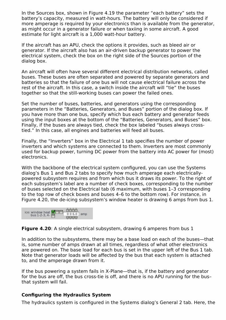
In the Sources box, shown in Figure 4.19 the parameter “each battery” sets the battery’s capacity, measured in watt-hours. The battery will only be considered if more amperage is required by your electronics than is available from the generator,as might occur in a generator failure or when taxiing in some aircraft. A good estimate for light aircraft is a 1,000 watt-hour battery.
If the aircraft has an APU, check the options it provides, such as bleed air or generator. If the aircraft also has an air-driven backup generator to power the electrical system, check the box on the right side of the Sources portion of the dialog box.
An aircraft will often have several different electrical distribution networks, called buses. These buses are often separated and powered by separate generators and batteries so that the failure of one bus will not cause electrical failure across the rest of the aircraft. In this case, a switch inside the aircraft will “tie” the buses together so that the still-working buses can power the failed ones.
Set the number of buses, batteries, and generators using the corresponding parameters in the “Batteries, Generators, and Buses” portion of the dialog box. If you have more than one bus, specify which bus each battery and generator feeds using the input boxes at the bottom of the “Batteries, Generators, and Buses” box. Finally, if the buses are always tied, check the box labeled “buses always cross-tied.” In this case, all engines and batteries will feed all buses.
Finally, the “Inverters” box in the Electrical 1 tab specifies the number of power inverters and which systems are connected to them. Inverters are most commonly used for backup power, turning DC power from the battery into AC power for (most) electronics.
With the backbone of the electrical system configured, you can use the Systems dialog’s Bus 1 and Bus 2 tabs to specify how much amperage each electrically-powered subsystem requires and from which bus it draws its power. To the right of each subsystem’s label are a number of check boxes, corresponding to the number of buses selected on the Electrical tab (6 maximum, with buses 1–3 corresponding to the top row of check boxes and buses 4–6 to the bottom row). For instance, in Figure 4.20, the de-icing subsystem’s window heater is drawing 6 amps from bus 1.
Figure 4.20: A single electrical subsystem, drawing 6 amperes from bus 1
In addition to the subsystems, there may be a base load on each of the buses—that is, some number of amps drawn at all times, regardless of what other electronics are powered on. The base load for each bus is set in the upper left of the Bus 1 tab. Note that generator loads will be affected by the bus that each system is attached to, and the amperage drawn from it.
If the bus powering a system fails in X-Plane—that is, if the battery and generator for the bus are off, the bus cross-tie is off, and there is no APU running for the bus–that system will fail.
Configuring the Hydraulics System
The hydraulics system is configured in the Systems dialog’s General 2 tab. Here, the

boxes labeled “Hydraulic Sources” and “Hydraulic Systems” represent the basics of the hydraulic system.
X-Plane can model up to four hydraulic pumps: one powered by the electrical system, one powered by a ram air turbine, and two powered by the engine. Check the boxes in the Hydraulic Sources portion of the General tab corresponding to the pumps your aircraft uses.
Figure 4.21: The “Hydraulic Sources” and “Hydraulic Systems that Depend on Hydraulic Sources” boxes of the Systems dialog’s General 2 tab
Each type of pump has a different max pressure, set beneath the pump’s checkbox.The units on the maximum pressure are not specified; the hydraulics modeling is not detailed enough for the units to matter, so they can be anything. The only thing that matters here is the ratio between the different pumps, and it only matters thenin the case of failure.
To the right of the hydraulic sources are the systems that depend on the hydraulics.If the hydraulic pumps fail, the systems represented by each checked box will also fail. Most of the systems here are self-explanatory.
The box labeled “manual reversion” controls the extent to which, following a hydraulic system failure, the flight controls continue to operate. This is set as a ratioof their normal full operation.
The group of settings in the middle specifies how the landing gear fails in the event

of a hydraulic failure. If the landing gear depends on hydraulics, it can have one of three behaviors in the event of failure: it can remain retracted, remain extended, or extend and remain there if the craft’s indicated airspeed is below a certain threshold. Select the radio button appropriate for your aircraft here. If the “fail downbelow…” option is selected, you must also set the threshold speed, in knots indicated airspeed.
If you’re using an emergency gear or flap pump in the instrument panel (used for extending the gear or flaps manually in the event of a power failure), you can use the “manual gear pumps” and “manual flap pumps” fields to set the number of times you must “pump” the button in X-Plane for the equipment to actually extend. These located at the bottom of the Hydraulic Systems box.
Configuring the Pressurization System
An aircraft’s pressurization system is set up using the Pressurization box (seen in Figure 4.22) found in the General 2 tab of the Systems dialog box. There, use the “maximum allowable pressurization” field to set the cabin pressure that the system is capable of providing, measured in pounds per square inch (psi). Standard atmosphere on Earth is 14.7 psi at sea level.
Figure 4.22: The Pressurization box, found in the General tab of the Systems dialog box
Below the maximum allowable pressurization is the emergency pressurization altitude. When the “dump to emer alt” button is pressed in the aircraft’s panel in X-Plane, this is the altitude that the pressurization system will match.
Checking the first box, labeled “auto-manage pressurization,” will cause X-Plane to control the pressurization, maintaining the air pressure of 7,500 feet above mean sea level until the maximum allowable pressurization is reached.
Checking the bottom box, labeled “dump pressure below 1000 ft,” will cause the pressurization system to equalize pressure with the outside air when the altimeter reads 1000 feet.
Finally, you can enter an amount for bottled oxygen available to be used by crew in cases of pressurization failure.

Configuring the Avionics System
The avionics system is comprised of the electronics used on an aircraft, including the systems used for navigation, communication, and the monitoring of other systems’ performance. Most of the avionics setup in X-Plane is performed when designing the panel, as described in Chapter 5, Creating an Instrument Panel. However, the “back-end” (such as specifications for how the instrument displays work) are set using the Systems dialog box, launched from the Standard menu. Later, when designing the instrument panel, you will add the specific instruments your aircraft uses.
Configuring Instrument Performance Ranges, Display Limits, and Colors
Prior to adding the instruments themselves (again, as described in Chapter 5, Creating an Instrument Panel), you can configure the instrumentation’s “back end,” the features of the instruments which will change based on your aircraft’s specifications. This includes performance ranges, which are set in terms of red-line, yellow, and green ranges. Additionally, it includes the instruments’ display limits, such as the maximum speed displayed by the airspeed indicator.
The aircraft’s performance ranges are set using the Limits 1 and Limits 2 tab of the Systems dialog box (found in the Standard menu). These tabs are used to set the operational and limiting temperatures, pressures, voltages, etc. of various systems on the aircraft. This information should be available in the aircraft’s Pilot’s Operating Handbook (POH). Note that this information is not used in the flight model; it controls only what the instruments display.
Figure 4.23: The columns for redline, yellow, and green ranges in the Limits tab
In addition to setting the red, yellow, and green ranges for the aircraft’s systems, the Limits 1 and Limits 2 tabs determine the units used in displaying torque, temperature, and power.
To configure the colors used in the instrument displays, open the Systems dialog box from the Standard menu and select the Arc Colors tab. Here, you can set the (decimal) RGB values for each of the three standard ranges. By default, the “green”arc has an RGB value of (0, 1, 0), the “yellow” arc a value of (1, 1, 0), and the red a value of (1, 0, 0).
Finally, if you don’t want to use X-Plane’s default instrument limits, you can set the range of values displayed by opening the Limits dialog box from the Standard menu. Here, two tabs are used for setting the range of values displayed on “round” instruments and two tabs are used for digital instruments.

In the case of round instruments, check the box next to a measurement (such as VVI, ITT, N1, etc.) to set (in order from left to right):
• the minimum value displayed,
• the maximum values displayed,
• the angle on the dial at which the minimum value is displayed, and
• the angle on the dial at which the maximum value is displayed.
In setting the angles, 0 degrees is the top of the instrument. Angles can be positive or negative, and can even be greater than 360 if you would like the dial to wrap around.
To use a different (compressed) scale for the high-end of an instrument’s range, check the box on the right of the angle settings labeled “halve over.” Then, beginning at the value you select, the scale will be halved, so it will take 2 units to move the instrument hand the same amount that 1 unit moves it at the low end of the scale. This is most often used in the airspeed indicators of high-speed airplanes,where it allows a greater range of speeds to be “compressed” into the display.
In the case of digital instruments, checking the box for a measurement allows you to set the offset, scale, and the number of digits used in displaying that measurement. The offset is a value added to the X-Plane value when displaying thismeasurement in the panel (this may be positive or negative). The scaling value will be multiplied by the X-Plane value to determine the number displayed in the instrument panel. The “digits” value determines the total number of digits used in displaying this measurement, while the “decimals” value determines only the number of decimals used.
Setting V-Speeds and G Limits
In addition to red, green, and yellow ranges, the instruments need standard operating markings. These include “v-speeds” (such as the maximum cruise speed, stall speed, and so on), as well as g limits. With the exception of the g limits, these will not be factored into the flight model; they may, however, be used in the airspeed indicator. To set these, open the Viewpoint dialog box from the Standard menu. There, on the left side of the General tab, you can set the following:
• Vmca, the minimum speed below which you can still steer the aircraft with one
engine disabled and the other at full throttle
• Vso, the speed below which the airplane will stall with the flaps deployed
• Vs, the speed below which the airplane will stall with the flaps retracted
• Vyse, the optimal climb speed with one engine disabled
• Vfe-m, the maximum allowable speed for fully extended flaps
• Vfe–1, the maximum allowable speed for first-notch flaps

• Vle, the maximum allowable speed for extended gear
• Vno, the maximum allowable speed for normal operation
• Vne, the maximum allowable speed (the craft’s airframe will fail if this speed is
exceeded by more than about 25%)
• Mmo, the maximum allowable Mach number
• Positive g limit, the maximum allowable positive g load (the craft’s airframe will fail if this limit is exceeded by more than about 50%)
• Negative g limit, the maximum allowable negative g load
Note that, unless noted, all values above are in knots.
If you cannot find official g limit values, 4.0 is a good guess for most general aviation aircraft. At g loads more than 50% above these values, if the appropriate settings are enabled in X-Plane, structural damage will occur-probably in the form ofa wing being torn off!
Note that, depending on your engine configuration, some of the values listed above may not be visible. Any of these markings can be left off the instruments by simply setting their values to zero. Note also that, though X-Plane does not take these speeds into account for performance prediction, it may use them for niceties like the plane’s starting speed when selecting an approach.
Configuring the Autopilot
For general settings that control autopilot behavior, select the Systems dialog from under the Standard menu. On the General 1 tab, start by choosing a preconfigured or custom autopilot. Preconfiugred options include:
• Airliner - Like X-Plane Custom, but with the addition of new auto throttle modes suitable for airliners, flight director selection instead of source selection, auto land capability and a different behaviour of CWS mode.
• GFC700 - Default autopilot of the Garmin G1000 digital flight deck. This hides other configuration options and configures the autopilot internally to behave like the Garmin GFC–700, which is a high-end position-based digital autopilot.
• STec 55 - High-end general aviation dual-axis rate-based digital autopilot. Most notably, this autopilot does not have buttons with toggle logic, so you cannot press the button of an active mode to go back to a default mode. You always have to select a new mode to cancel an old mode. This autopilot supports GPSS, by pressing the NAV button twice. (Used in the default analogue C172.)
• STec w/ alt presel - Like the S-Tec 55, but with an altitude pre-selector that allows arming altitude capture.
• KAP 140 with alt - Hides other configuration options and configures the autopilot to behave like this single-axis general aviation rate-based autopilot. This acts on the roll axis only, does not have an elevator or trim servo, and
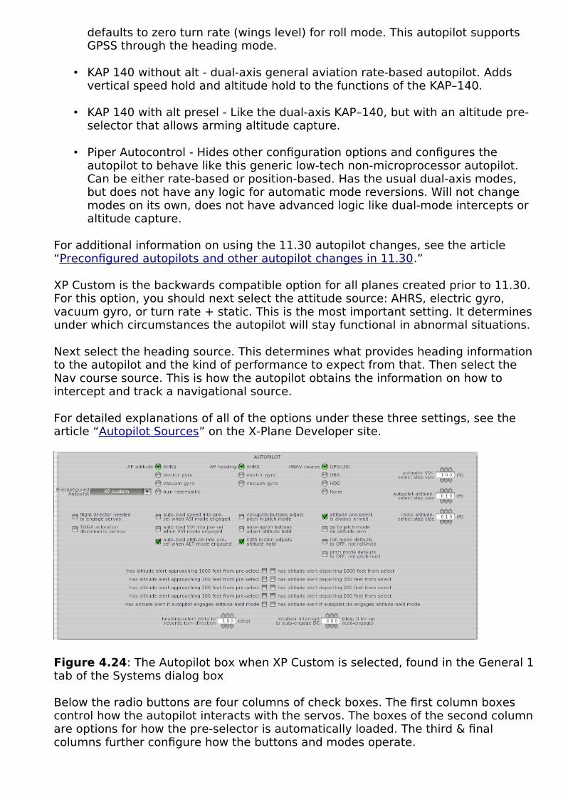
defaults to zero turn rate (wings level) for roll mode. This autopilot supports GPSS through the heading mode.
• KAP 140 without alt - dual-axis general aviation rate-based autopilot. Adds vertical speed hold and altitude hold to the functions of the KAP–140.
• KAP 140 with alt presel - Like the dual-axis KAP–140, but with an altitude pre-selector that allows arming altitude capture.
• Piper Autocontrol - Hides other configuration options and configures the autopilot to behave like this generic low-tech non-microprocessor autopilot. Can be either rate-based or position-based. Has the usual dual-axis modes, but does not have any logic for automatic mode reversions. Will not change modes on its own, does not have advanced logic like dual-mode intercepts or altitude capture.
For additional information on using the 11.30 autopilot changes, see the article “Preconfigured autopilots and other autopilot changes in 11.30.”
XP Custom is the backwards compatible option for all planes created prior to 11.30. For this option, you should next select the attitude source: AHRS, electric gyro, vacuum gyro, or turn rate + static. This is the most important setting. It determines under which circumstances the autopilot will stay functional in abnormal situations.
Next select the heading source. This determines what provides heading information to the autopilot and the kind of performance to expect from that. Then select the Nav course source. This is how the autopilot obtains the information on how to intercept and track a navigational source.
For detailed explanations of all of the options under these three settings, see the article “Autopilot Sources” on the X-Plane Developer site.
Figure 4.24: The Autopilot box when XP Custom is selected, found in the General 1tab of the Systems dialog box
Below the radio buttons are four columns of check boxes. The first column boxes control how the autopilot interacts with the servos. The boxes of the second columnare options for how the pre-selector is automatically loaded. The third & final columns further configure how the buttons and modes operate.

To further configure a custom autopilot in Plane-Maker, or fine-tune an existing one,first go to the Expert menu and click on Artificial Stability. Go to the Autopilot tab and check the “use custom autopilot constants” box. A number of controls will appear that specify the autopilot constants for your airplane.
Figure 4.25: The autopilot constants available when the “use custom autopilot constants” box is checked
Let’s examine what each of these autopilot constant controls do. First, let’s take a look at the top box, where the controls deal with the throttle control of the aircraft. The first box adjusts how quickly the autopilot changes the throttle setting. Smaller values smooth out variations in acceleration & deceleration, but also slow down throttle response time. “Speed prediction” tells the autopilot how many seconds it takes for the aircraft to respond to the throttle changes it makes. The last option controls the sensitivity of the autopilot in reacting to an error in speed. Higher numbers decrease the sensitivity, and the autopilot will wait longer before applying full throttle to correct a deviation.
Next, let’s talk about correcting heading.
Tuning Autopilot Roll
Roll Controls
The roll prediction control is found in the middle box of the Autopilot tab, at the top of the left column, highlighted in blue in the following image.
Figure 4.26: The autopilot roll error control options

“Roll prediction” tells the autopilot how far into the future it should look. If the planetends to wander slowly left and right, always behind its mark, or it overshoots and then wanders slowly off in the wrong direction, then it clearly is not anticipating enough. In that case, an increase is required in the roll prediction to make the autopilot anticipate more. If, however, the airplane starts flopping back and forth hysterically every frame, the autopilot is clearly anticipating too much; a smaller rollprediction is needed.
One second is a good starting point for this control—after all, when real pilots fly, it’s a good bet that they enter controls based on where the plane will be in one second, rather than where it is at the moment.
Underneath the roll prediction box is the “roll response time” control, which determines the delay in how long it takes the aircraft to respond to roll commands. Adjusting the aircraft’s roll does not create an instantaneous change in any aircraft. This control lets the autopilot know how long it will take to see the results of the adjustments.
The “roll error for full aileron” control is found in the middle box of the Autopilot tab,in the middle column, highlighted in orange in Figure 4.26 above.
When flying a real plane, a pilot decides on a roll angle to make a turn. He or she then decides to deflect the ailerons a certain amount of degrees to achieve the desired bank angle.
This control specifies to the autopilot how many degrees off the aircraft must be from the desired roll angle before it puts in full aileron. If this is set to a very small number, the autopilot will put in full aileron for even the tiniest of roll errors. This will cause the plane to over-control and flutter madly left and right like an over-caffeinated pilot! On the other hand, if this control is set to a very large number, then the autopilot will hardly put in any aileron input at all. In that case, the plane will always wander off course a bit, because it will never move quickly enough to get back on course. What this control really determines is how aggressively the ailerons are applied.
A good starting point for this control is 30 degrees. This means that if the roll angle is off by 10 degrees, the plane will apply one- third aileron to correct when at low speed—not a bad idea.
Beneath this control is the roll rate, measured in degrees per second. This tells the autopilot how fast to roll the plane. This should be based on what the aircraft is realistically capable of. The autopilot will overshoot turns if this is set too high, or fail to complete a turn in time if it is too low.
The “roll tune time” control is found in the right-hand column, seen in yellow in Figure 4.26.
In the real plane, a pilot will trim out any loads with trim if it is available. The roll tune time determines how long the autopilot takes to run the trim. If the autopilot waits too long to trim out the loads, it may be slow and late in getting to the correctangle. A good starting point for this control is 5 seconds.
Localizer Control
The “localizer CDI gain” control is found at the bottom of the middle column. This sets the number of degrees of heading change that the autopilot will pull for each

degree of error on the localizer (which is the same as saying for each dot of CDI deflection).
If the aircraft is off course by about one degree, and the autopilot corrects only one degree, the craft would be flying right towards the airport, never intercepting the localizer until it got to the transmitter on the ground. Thus, a good starting point for this control is 10 degrees, forcing the plane to nail that HSI now.
Next we will discuss correcting pitch; the discussion will be almost exactly the sameas roll, really.
Tuning Autopilot Pitch
Pitch Controls
The “pitch prediction” control is found in the bottom box of the autopilot tab window, at the top of the left column, highlighted in blue in Figure 4.28 below.
Figure 4.28: The autopilot pitch control options
This control determines how far into the future the autopilot will look. If the plane is always wandering up and down when trying to hold a given vertical speed, always afew steps behind where it needs to be, then more anticipation is clearly called for—the pitch prediction control needs to be set to a larger number. Conversely, if the plane is always resisting motion towards the desired pitch, then it is probably anticipating too much, and a smaller number is called for. Once again, these numbers need to be tuned in pitch and roll modes, or maybe heading and vertical speed modes, to get them set perfectly, with nice, snappy, precise autopilot response, before the autopilot is tested on an ILS.
A good starting point for this control is one second.
“Pitch error for full elevator” is at the top of the middle column, highlighted in red inFigure 4.28. This control is to pitch as the “roll error for full aileron” control is to roll.It determines how much error between desired and actual pitch is required for full elevator deflection. Remember that the autopilot will automatically reduce the control deflections as the plane speeds up, limiting to maybe 50% control deflection, so it isn’t necessary to worry about the system really going to full deflection.
If the plane takes too long getting the nose up to track a new vertical speed, then a smaller pitch error for full elevator value is needed. This will cause the plane to be more aggressive with the elevator. Of course, if the plane starts flapping about madly, a larger value is needed, telling the plane to stop deflecting the elevator so much.
By itself in the right hand column of this box, is the “pitch tune-time” control, also highlighted in yellow in Figure 4.28. It sets the time required to trim, similar to the roll tune time control described above. If this is set to too small a number, the plane

will constantly be wandering up and down as it plays with the trim, as it will always be too quick to modify the trim.
This control should probably be set between 5 and 10 seconds.
The final pitch control, “pitch degrees per knot,” is found at the bottom of the left column, seen in Figure 4.28, highlighted in purple. It determines how many degrees the autopilot will pitch the craft up or down in order to correct for a one-knot difference between the actual speed and the one set in flight level change mode. A good starting point is 0.2 degrees.
Glideslope Controls
“Glideslope CDI prediction” is found in the bottom box of the Artificial Stability window, in the left-hand column, highlighted in orange in Figure 4.28.
A good pilot will anticipate where the glideslope will be in the near future as he or she controls the pitch. If the pitch is not anticipated enough, the aircraft will be correcting up and down all the way down the glideslope. If the pitch is anticipated too much, the craft will never get to the glideslope, as it will always be shying away from it as soon as the needle starts to close in.
A good starting point for this control is 8 seconds.
The “glideslope CDI gain” control is found in the bottom box of the window, at the bottom of the middle column, as seen in the green box in Figure 4.28.
It tells the autopilot how much it should change the pitch for each degree of glideslope error. For example, if it is set to 5 degrees (a reasonable value), the autopilot will pitch up 5 degrees for each degree it is below the glideslope. The greater the number entered here, the more the command bars will move to meet the glideslope.
Summary of Custom Autopilot Controls
To summarize, the autopilot settings are complicated and they interact. Start with the default settings that appear when the custom autopilot constants box is checked, then “sanity-check” how the plane handles in test scenarios.
Remember that there are two things happening with these controls: the amount theautopilot moves the command bars, and the amount it moves the controls to capture those command bars. Therefore, if the command bars are not behaving as they should, one of the command bar variables needs to be set. On the other hand, if the command bars are fine, but the airplane isn’t tracking those bars correctly, one of the flight control tracking variables needs to be set so that the autopilot will “grab” the bars.
Remember there are two steps to tuning these autopilot controls:
1. Decide how to move the bars (CDI gain and CDI prediction), then
2. Decide how to move the controls (pitch and roll error, pitch and roll prediction).
Finally, remember that there is one number that controls how hard we try to get to our target (CDI gain, roll and pitch error—think of this as a “spring constant”) and one number that controls our anticipation (CDI prediction, roll and pitch prediction—

think of this as a damping constant).
Configuring GPS and FMS
You can specify whether the GPS auto-adjusts to desired track in the Instruments box found in the General 1 tab of the Systems dialog.
To provide a user-interface to the underlying FMS/GPS you selected in the Systems screen, select an instrument from the list under radios/GPS FMS in the panel editor screen. Options with “_screen” in the name are intended for designers who create their own bezels.
If you are including a second unit for the copilot, it must be explicitly flagged by checking the “copilot” box in the bottom bar of the panel editor.
Configuring the Starter
Figure 4.29: The Starter box found in the Start/Spoolup tab of the Engine Specs dialog box
To configure the engine’s starter, start with the “starter torque” and “starter design RPM” parameters, located in the “Starter” box of the Start/Spoolup tab in the Engine Specs dialog, and seen in Figure 4.29. Plane Maker will re-calculate how longit takes the starter to reach the % N2 each time this number is changed. Choose whether your starter is electric or air-driven. You can also select up to four additional behaviors for the different engine types that will activate when the starter button is pressed in X-Plane.
Configuring the Fuel System
The aircraft’s fuel system is configured using the Weight & Balance dialog box, launched from the Standard menu. To begin setting it up, go to the Weight & Bal tab and enter the maximum amount of fuel, in pounds, that the aircraft can carry into the “fuel load” parameter box.
Next, move to the Tanks tab. In this tab, there are nine fuel tanks able to be added. Each tank holds a ratio of the aircraft’s maximum fuel, which is set using the “tank #x ratio” input box. The total of all tanks’ ratios must add up to 1.000. For instance,

if an aircraft had two fuel tanks, one in each wing, each tank might hold 0.5 of the total fuel.
Use the “fuel pump pressure” setting to set the relative pressure of the fuel tanks. This will determine which tanks are emptied first if more than one is selected. For instance, If tank 1 should empty a little bit before tank 2 and long before tank 3 when all 3 tanks are selected, you might set their fuel pump pressures as in the table below.
Tank 1 20 psi
Tank 2 17 psi
Tank 3 10 psi
Relative fuel pump pressures
Finally, the fuel tanks can be placed on the aircraft using the standard position controls (as described in the “Fundamental Concepts” section of Chapter 3). X-Planeconsiders the inertial properties of slinging fuel around at various distances from the aircraft’s center of gravity, so placing the fuel tanks in the correct location is important in making sure the craft handles correctly. Note that, when placing fuel tanks, you are really only placing the tanks’ center of gravity; X-Plane assumes the tanks are physically large enough to hold the weight of fuel you have specified.
Note also that the fuel tank selectors in the instrument panel will select left and right tanks based on the physical locations you specify here.

Creating an Instrument PanelCreating a basic 2-D instrument panel in Plane Maker is as easy as choosing a panelbackground image and dragging the instruments you want where you want them. Creating panels that use generic (user-created) instruments are more complicated, as are 3-D panels; generic instruments are discussed in depth below, while 3-D objects and panels are discussed in a later section entitled “Creating 3-D Objects foran Aircraft.”
Before we get started, let’s clarify some of the terms associated with panels and thecockpit.
• A Panel is a 2-d image with multiple instruments that is used to create a 2-d simulation of part of a real airplane cockpit.
• A cockpit object is a 3-d object (OBJ file) that is used to create a 3-d simulation of an entire real airplane cockpit.
• The panel texture is a dynamic texture (a texture created and updated continuously by X-Plane) that is created by drawing a panel and converting it to a texture for use in an object.
• A 2-D view is a view that displays one panel, with the camera angle fixed. The user can scroll the panel up, down, left and right if it is larger than the screen, and can tilt the camera down to help with landings.
• A 3-D view is a view that displays a cockpit object, where the user has complete freedom to move or rotate the camera in any way desired.
• The 2-D panel is the panel that is used when looking forward in a 2-d view. It typically has the plane’s main instruments. It is also used to form the panel texture in most cases.
• The 3-D panel is a panel that is used to form the panel texture. See below formore information.
• A panel background is a single large image that defines the size and appearance of the panel. It does not change during flight.
• An instrument background is a single image that defines the non-moving part of an instrument. It is “burned in” to the panel background during panel load.
• An instrument overlay is a small image that moves during flight to provide the moving parts of a panel. Instruments can have up to four overlay layers.
Introduction to Panel Creation
With the aircraft whose panel you want to design open, open the Standard menu and click Panel: 2-D. The panel design dialog box will appear.
This window is made up of a number of different sections. The buttons in the toolbarat the top of the screen (labeled 1 in Figure 5.1) perform a variety of functions; mouse over each button to get a description as well as the keyboard shortcut that does the same thing, where available. For instance, mousing over the far left

button, whose icon is a floppy disk, tells us that this button saves the file, and that you can also save by pressing Ctrl + s.
Two groups of information panes lie on the left and right of the screen, respectively.On the left is the Instrument List, which is combined with the Preview, Description, and Properties panes, and on the right is the Hierarchy, combined with the Key Frames pane. These left and right groups can be displayed or hidden by clicking thelarge Instrument List and Hierarchy buttons at the top of the screen, respectively.
Creation of an instrument panel then proceeds this way. First, find the instrument you’re looking for in the instrument list (labeled 2 in Figure 5.1) and click on it. For instance, in Figure 5.1, the general aviation altimeter, whose filename is alt_GA.png,is selected. With an instrument selected, you can see what it will look like in the Preview tab (labeled 3 in Figure 5.1). Beneath this is the Description tab (labeled 4 in Figure 5.1), which details what the selected instrument does.
Figure 5.1: The panel design dialog box with its various parts numbered
Having found the instrument you’re looking for, click it in the instrument list and drag it into the layout pane, labeled 5 in Figure 5.1. Doing so will cause the instrument to also be listed in the hierarchy pane, labeled 6 in Figure 5.1. With an instrument in the panel, click on it to select it; selecting an instrument in either the layout or the hierarchy pane will cause it to be selected in both.
When an instrument has been added to the panel layout, it will appear in the Hierarchy pane. You can select an instrument from the layout pane by clicking its name here. Additionally, you can set its status to visible or invisible by clicking the eye icon to the left of it, and you can set it to locked or unlocked (that is, unmovable or movable) by clicking the padlock icon.

When an instrument is selected in the layout and hierarchy panes, the Properties tab (labeled 7 in Figure 5.1) will display its settings. This includes what lighting is used on the instrument, which electrical bus the instrument is on, and what Tool Tip(if any) will be displayed when the Show Instrument Descriptions setting is activatedand it is moused over in X-Plane. The comment property is simply for use in designing and will have no effect in X-Plane.
To select multiple instruments in either the hierarchy pane or the layout pane, hold down the Shift key and click the desired instrument. To group instruments together in the hierarchy pane, select them and press the G key. With a group created, you can also click and drag other instruments into the group in the hierarchy pane.
With an instrument selected, you can drag it around to reposition it, or use the arrow keys to move it by very small amounts. If there is more than one instrument in the panel, guide lines will appear to which the instrument will “snap,” allowing you to align instruments perfectly.
Use the = and - keys or your mouse wheel to zoom in and out in the layout pane. Topan your view of the panel left and right, you can right click (or hold the Control keyand left click) on the panel and drag it; alternatively, you can use the left, right, up, and down arrow keys to “nudge” the panel each direction, and press Shift with an arrow key to jump to the far edge in a given direction. Press the Alt key to view each instrument’s index (duplicates of a single instrument will have different indicesin order to differentiate them). Click and drag anywhere in the layout pane to form abox that selects multiple instruments. To delete an instrument, select it and hit the Backspace key.
If two instruments are placed on top of one another in the layout pane, the instrument closest to the bottom of the list in the hierarchy pane will be displayed on top of the instruments higher up the list. To change an instrument’s name, double-click it in the hierarchy pane and type its new name.
Finally, in the very bottom of the window is the status bar (labeled 8 in Figure 5.1). Here, you can see the level of zoom for the panel layout pane, the name and position of the currently selected instrument, the object’s size (as a ratio compared to its original size), and whether the instrument uses the copilot’s pitot tube.
Setting a Panel Background
Before beginning the layout, you may want to create the background image that your panel will use. Plane Maker will supply a default panel image based on your cockpit type setting specified at the top of the Viewpoint dialog box (e.g., General Aviation, Airliner, Fighter, etc.), but you may want a different image for a number of reasons. X-Plane 11.30 allows 4k panels so panel size is limited to a maximum of 4096 x 4096 pixels, and a minimum of 1024 x 1024 pixels, but the image does not have to be square. Note that 4k panels may heavily impact performance; if so, go back to the earlier 2k size maximums (2048 x 2048 pixels).
Panel backgrounds in Plane Maker can follow one of two naming conventions. The old convention is simply to name the image “Panel.png” (without the quotes, of course). As of version 9, Plane Maker will still work with a panel named this way. The new convention, and the one you should use when creating new aircraft, is to name the image to match the “cockpit” setting in Plane Maker’s Viewpoint dialog box.

For instance, if the cockpit setting in the Viewpoint dialog were set to General Aviation, the panel image would be named Panel_General.png. If it were instead set to Airliner, the image would be named Panel_Airliner.png.
The official names for panels are the same as in the folder Resources/bitmaps/cockpit/-PANELS-/ and are:
• Panel_General.png
• Panel_Airliner.png
• Panel_Fighter.png
• Panel_Glider.png
• Panel_Helo.png
• Panel_Autogyro.png
• Panel_General_IFR.png
• Panel_Autogyro_Twin.png
• Panel_Fighter_IFR.png
In order for Plane Maker to find your background, you must (re)name it using one of these conventions and save it in: [Your aircraft folder here]/cockpit/-PANELS-/ or [Your aircraft folder here]/cockpit_3d/-PANELS-/
Thus, the panel image for X-Plane 11’s Cessna 172 SP is in the following folder: X-Plane 11/Aircraft/General Aviation/Cessna 172SP/cockpit_3d/-PANELS-/
With your panel image has been saved to the correct folder, it should appear the next time you open the Panel dialog in Plane Maker. With the panel loaded, you can begin dragging and dropping instruments from the list into your cockpit.
Generic (Custom) Instruments
Generic instruments are designed to give you more flexibility in creating 2-d panels.They are instruments on the 2-d panel that are configured based on custom parameters, artwork and datarefs. The purpose of generic instruments is customization, not easy creation; if you do not want to make your own artwork or animations, you should use the hundreds of pre-made instruments.
The generic instruments live in the “Generic” folder in the main instrument list in Plane Maker. You can show only the generic istruments by clicking the “Generic” button at the top of the instrument list as well. There are only 12 generic instruments; each type represents a different “mechanism” (e.g. needle vs. handle).All of the properties available in pre-made instruments are customizable in generic ones, as well as many others. Remember, hovering the mouse over any field will show a description of what it does.
Properties Common to All Generic Instruments
The properties of a generic instrument must be set using the options in the

“Properties” box in the bottom left corner of the instrument screen.
PNG file
All generic instruments reference a PNG image file. While there are default image files that will be used if the PNG file is blank, you should not use the default images.If you are going to use generic instruments, always provide your own artwork! The generic instruments are provided only to be place-holders so that you can see the new instrument in the editor in Plane-Maker before you pick your own instruments. These defaults may change in the future, breaking your panel. Use your own images, which will not change.
Image files should be contained within the “generic” subfolder of the “cockpit” folder of your aircraft. You can build sub-folders within the generic folder. The cockpit folder goes in the aircraft folder - ie F:\X-Plane 11\Aircraft\Helicopters\SH–60B\cockpit\generic.
Click in the “image” field to pick new artwork. The layering conventions (–1, –2, etc.)apply to generic instruments; how the layers are used depends on the instrument type. Changing the PNG file will change the real-time preview.
Note: if you are using a 3-d cockpit panel (see 3D_Panel) then the cockpit_3d/generic folder will be used as an image source first.
Dataref/Command
All generic instruments are driven by a main dataref, which defines where the input values come from that move the instrument. There is one exception: the trigger generic instrument uses a command rather than a dataref. In all cases, the instrument has some mechanism to scale the value of the dataref for display.
You should try to use the datarefs in sim/cockpit2/ for generic instruments, since these datarefs are designed for in-cockpit use.
Generally:
• sim/cockpit2 are in-cockpit INDICATIONS - they will show the wrong values when there is a systems failure. For example, the airspeed in sim/cockpit2 willgo to zero as the pitot tube ices up.
• sim/flightmodel2 are the real physics-simulation values - they are correct always, and thus are good for modeling the external plane. For example, the AoA in sim/flightmodel2 will always show the real AoA no matter what electrical and vacuum systems fail - this would be appropriate for the AoA sensor mechanism on the outside of the plane.
• both sim/cockpit2 and sim/flightmodel2 work correctly for any plane (the user’s or multi-player)…that is, the sim/flightmodel2 datarefs will show the values for the AI/multiplayer planes when read from an object attached to an ACF loaded as an AI/multiplayer plane.
• The older sim/cockpit and sim/flightmodel datarefs are not carefully divided into cockpit (with failures) vs. physics (no failures), and always show the user’s plane, even when your OBJ is attached to another plane. So it is best to use sim/cockpit2 for generic instruments and sim/flightmodel2/ everywhere else.

If you pick a dataref that is an array, an “index” field will appear in the instrument editor. This is how, for example, you pick which engine an N1 instrument listens to. (The N1 dataref is an array, with one item in the array for each element.) You do nottype [0] into the dataref name in PlaneMaker.
Lighting Mode and Knob Number
Generic instruments can have one of seven lighting modes, which affect how instrument overlays are drawn. (The background is simply burned in.)
• Mechanical: the instrument is lit by the flood and spot lights. The instrument isalways drawn (albeit very dark if it is night and there is no power.)
• Back-Lit: the instrument’s regular texture is lit by the flood and spots. The _LITtexture is added to it, regulated by the knob number if there is power.
• Glass: the instrument is lit by the appropriate instrument-lighting knob. The instrument disappears if there is no power.
• Glass (Translucent): same as glass, but when the instrument is dimmed, it fades to transparency, not to black.
• Glass/Backlit (Auto Adjust): in addition to the regular features of glass or backlit lighting, auto adjust will simulate a light that is tied to a photo-cell and will appear ‘bright and readable’ during the day and night without user intervention.
For glass and mechanical instruments, at night with power the _LIT overlay texture is swapped in for the regular overlay texture.
Glass and back-lit generic instruments listen to the “Knob Number” to specify their lighting. You can use a knob of –1 to have a lit instrument that is always on, for example.
Power Source & Bus Selectors
This defines what power source the instrument draws from. A power failure will cut off instrument lighting, but will not necessarily fail the instrument itself. (For example, a vacuum-driven dataref should not be affected by an electrical failure.) For each bus defined in the airplane, a check-box lets you attach power to the instrument; the instrument will power if any selected bus is powered. The choices are:
• None - the instrument does not require power. • Bus 1 - the instrument gets power from bus 1. • Bus 2 - the instrument gets power from bus 2. • Any - the instrument can get power from either bus 1 or bus 2. Check both
boxes. • Avionics Master Switch + Bus 1 - the instrument gets power from bus 1, but
only when the avionics master switch is on. • Avionics Master Switch + Bus 2 - the instrument gets power from bus 2, but
only when the avionics master switch is on. • Avionics Master Switch + Bus 1 & Bus 2 - the instrument gets power from
either bus, but only when the avionics master switch is on.

Clipping & Skewing
Any instrument can have “clipping” enabled, which limits drawing of an instrument’s overlays to within the bounds of the instrument background. Any generic instrument can be “skewed” as well- that is, you can drag the corners of theinstrument to change its shape to a trapezoid or quadrilateral. The distortion applied to the instrument will be perspective-correct, and is meant to align moving parts on overhead panels.
Skewing does interact with overlays/moving parts and clipping. Skewing does not affect burned-in backgrounds or hot-spots. Skewing is not recommended for instruments that can be dragged.
Visibility Filters
The three “show if” fields let you apply optional rules to hide the instrument. You specify a dataref and a value - if any of the rules is utilized in the editor but the rule is not true (e.g. the rule is sim/hud_power needs to be 1, but sim/hud_power is not 1) then the generic instrument will disappear.
This system has a few potential uses:
• You can use the needs == rule to tie the visibility of your instrument to a plugin-created dataref.
• You can hide instruments depending on things like the EFIS or EICAS mode switches.
• You can hide instruments in certain flight conditions.
Specific Generic Instruments
A general note on proportions: in many cases, the scaling of the instruments work by proportions, e.g. at this dataref value, show the needle at this angle.
In a few cases, where a straight numeric result must be computed, an offset and multiplier are provided for the dataref. The ratio is multiplied by the dataref before the offset is added.
Annunciators (gen_annun)
The annunciator is actually a special-case instrument in that it doesn’t use a datarefat all. Basically if the conditions are met, the upper image in the png file is used, otherwise the lower ones are used. (It is designed this way so you can create logic like “fuel flow too low” or “engine temp too high” or “gear is down”.)
Handles (gen_handle)
Handles are used for draggable controls like engines. Key frames map from the input dataref to vertical pixel offsets (from the center of the instrument). Click radius defines how wide the hot spot for clicking is. If “detents” is enabled, the handle will be a bit sticky at the exact values specified in the key frame table. This lets you make a handle that tends to stay in certain positions, like a flap handle on airliners.
LEDs (gen_LED)
The LED dataref provides an LED-style numeric display of a dataref. The key frame table converts from the dataref to the numbers displayed. Digits and Decimals

controls the formatting of numeric input. Note that the PNG file must be fixed at 6 digits even if “digits” is less than 6. You can specify the width of the “period” digit inpixels - specify 0 to keep the period the same as all other digits. You can also specify the number of rows in the texture. The default of 0 will use the old six-row layout.
Needles (gen_needle)
The needle provides a steam-gauge-style instrument and is also capable of creatingheading bugs. The key frame table maps from the input value to degrees.
• Offset moves the needle away from the center by a certain number of pixels. This can be used to place a heading bug at the rim of the instrument or to position the needle on only one side of the instrument (without using transparency).
• If “is-draggable” is enabled, the user can drag the needle to change the dataref value. Use this for mechanical heading bugs.
-If “is-draggable” is enabled, then “click-radius” defines the hot-spot size. The hot spot is centered around the needle, with the offset taken into account.
• X and Y rotation offset lets you rotate the needle around a location other than the center of the instrument.
Pies (gen_pie)
The pie instrument creates a digital pie-style instrument, like you might see in an EICAS. The key frame table maps from dataref inputs to degrees. The lowest key frame defines the start point of the pie.
• If the pie dataref goes below the “low yellow” value the pie turns yellow.
• If the pie dataref goes above the “high yellow” value the pie turns yellow.
• If the pie dataref goes below the “low red” value the pie turns red.
• If the pie dataref goes above the “high red” value the pie turns red.
• The radius defines the pie size in pixels.
• Offset makes the pie into a “ring” arc instead of a “pie” arc.
Note that the properties for turning yellow and red are defined in dataref units, not degrees. So for example, for N1 you might do this:
Low red: 0 Low yellow: 0 High Yellow: 0.9 High Red: 1.0
Thus for an N1 (from 0 to 1.0) the low-end red/yellow zones are not used.
Pointers (gen_pointer)
A pointer moves its overlay image either left-right or up-down. The key frame table maps from the dataref to an offset in pixels from the center of the instrument. If theorientation is vertical, the pointer moves up-down with the dataref, otherwise it moves left-right. The offset parameter is a fixed offset in the direction that is perpendicular to the way the pointer moves. If “draggable” is true, the user can

drag the pointer (like a bug) to set the dataref, and “click radius” defines the hot spot size.
Radio Frequencies (gen_radiofreq)
The radio frequency rheostat increments or decrements a radio frequency dataref. The key frame table should be set to “linear” (e.g. mapping 0->0 and 1->1). The radio type defines the type of frequency that will be controlled and the editing mode. The rheostat will set the correct values (in hz) for the type of radio (E.g. wrapping around from 110 to 118.0 for a NAV radio).
For transponders and 1-ring ADFs, the “digits” field defines which one digit the rheostat will edit. Click radius defines the hot-spot size. The hot spot can be offset horizontally or vertically.
When you pick Com Radio or Nav Radio, the rheostat automatically has an inner and outer ring. When you pick ADF 3-Ring the rheostat automatically has 3 rings.
Rheostats (gen_rheostat)
The rheostat turns a dataref up and down, and optionally shows a rotating overlay. The key frame table maps from the dataref to degrees (to rotate the overlay). The rheostat’s range is limited by the low and high key frames in the key frame table.
• Click step defines how much the rheostat changes when the mouse is clicked once. This is in the output units, not dataref units.
• Hold step defines how much the rheostat changes when the mouse is held down for one second. This is in the output units, not dataref units.
• The “wrap-around” option will cause the underlying dataref to go to its lowest value once it goes past its highest value (and vice versa). For example, a heading bug rheostat would use this to make the bug “wrap” from 360 back to 0 degrees.
• Click radius defines the size of the hot spot.
• Hole radius defines a hole in the hot spot where you cannot click.
• The hot spot can be offset horizontally or vertically.
• Custom cursor lets you provide a custom cursor choice.
A note on units: if you do not use an overlay, you can set the key frame table to map linearly (e.g. 0->0, 1->1). In this case the click step and hold step would be in dataref units. But if you use an overlay, you’ll want to use degrees as the output of the key frame table - thus the click step is how many degrees to turn the knob per click.
One-way rheostats (gen_rheostat_one_way)
The one-way rheostat is like the normal rheostat except that the control can only beincremented. The one-way rheostat cannot have an overlay.
• Click step defines how much the rheostat changes when the mouse is clicked once. This is in the output units, not dataref units.

• Hold step defines how much the rheostat changes when the mouse is held down for one second. This is in the output units, not dataref units.
• Click radius defines the size of the hot spot.
• Hole radius defines a hole in the hot spot where you cannot click.
• The hot spot can be offset horizontally or vertically.
• Custom cursor lets you provide a custom cursor choice.
Generally you would utilize “one-way rheostats” in pairs…that is, two separate instruments, one which increments and one which decrements a given dataref.
Rolling Counters (gen_rolling)
The rolling counter shows a dataref’s value numerically - the key frame table maps from the dataref to the numbers displayed. The digits parameter determines how many digits the rolling tape is split into.
Rotary knobs (gen_rotary)
A rotary knob increases or decreases an integral dataref from 0 through a number of sections. The key frame table maps from the dataref to the animation phase you want to show. Phases larger than the number of digits wrap around to the beginning; phases smaller than zero cause the rotary knob to disappear. All clicks work in one output unit of the key frame table.
Positions defines the number of drawing phases in the rotary. Note that for rotaries that do not wrap, the clamped values are based on the key frame table, not the digits.
Rotary Type defines the way the mouse interacts with the rotary switch. The types are:
• Rotary: hot spots surround the rotary to provide X-Plane’s standard clickable-rotary interface. Each click change the value by one with clamping.
• Left/Right: clicks to the right side of the rotary increase the value, clicks to theleft side decrease, with clicks clamped to the extent of the key frame table.
• Up/Down: clicks to the top of the rotary increase the value, clicks to the bottom decrease, with clicks clamped to the extent of the key frame table.
• Push-Button: each click increases the value by one, wrapping around when the maximum is reached.
• Momentary: clicking down sets the maximum key frame value, releasing sets the minimum key frame value.
• No Click: clicking does nothing. Use this type of rotary as a display.
• Rheostat: holding down the mouse moves the rotary continuously like a rheostat. When this is selected, you must pick click and hold increment values.

• Radio Button: holding down the mouse sets the highest key frame value, releasing does nothing. This is useful for creating a series of rotaries where a click to each one sets a dataref to a certain absolute value.
The rotary is the only generic instrument that reads and writes its dataref and can handle a key frame table with gaps.
You can also customize:
• The custom cursor property, which lets you override the default cursor. • The radius of the hot spot. • The radius of a hole inside the hot spot that does not react to the mouse. • The hot spot can be offset horizontally or vertically.
Tapes (gen_tape)
The tape display shows a linear tape graphic - the key frame table maps from the dataref to a pixel offset from the instrument center. The tape starts at the position specified by the lowest key frame.
Text (gen_text)
The text display shows a “byte array” (or “data”) dataref as a human readable text string. The key frame table is ignored. This only works for byte-array type datarefs! Use the LED instrument for numeric datarefs. The X and Y offsets are pixel offsets toposition text drawing relative to the instrument.
Triggers (gen_trigger)
The trigger instrument makes a clickable region that invokes a command. Instead ofa dataref, a sim command is specified. The key frame table is ignored. The generic trigger has a two-state bitmap, toggling between the two images as it is pressed.
• The click radius defines the size of the hot spot.
• The custom cursor property lets you override the default cursor.
• The hot spot can be offset horizontally or vertically.
Put the two position images of the switch in one .png side by side - same size for each. Call the file something like switch–1.png. It may look ugly in Plane Maker, but it shows up nicely in X-Plane itself. Click on the switch in X-Plane and it will toggle the two images.
Sliders in the Panel
Basic sliders are designed for animations that X-Plane does not have a native mechanism for. The dataref for a slider can be used to animate an object or a generic instrument (or anything else, for that matter). Sliders are an advanced feature of aircraft design and were designed with programmers in mind. Sliders cannot be added to any of the default Plane Maker instruments, so using sliders requires an understanding of how to use the generic instruments as discussed in the section “Generic (Custom) Instruments” above.
Normally, a switch in the X-Plane panel is either on or off, and going between the two states is instantaneous. For instance, as far as X-Plane is concerned, an aircraft’s landing gear is either all the way up (with the background dataref

sim/cockpit2/controls/gear_handle_down set to 0) or all the way down (with said dataref set to 1). Thus, the landing gear switch in the instrument panel is either all the way up or all the way down. However, it may be desirable to animate the transition between these states; one might like to specify to X-Plane how long an animation should take. This is where sliders come in.
Essentially, the sliders act as a time-delay mechanism, running a sequence of ratiosover a set amount of time when a source switch is set. This lets you create animation sequences where a user sees the entire sequence.
The slider sub-system provides two datarefs that are most applicable to custom panel creation:
• “sim/cockpit2/switches/custom_slider_on” – which can control where the sliderSHOULD go
and
• “sim/flightmodel2/misc/custom_slider_ratio”– to show where it IS.
(A full list of the current datarefs is available in the X-Plane 11 folder, under Resources/Plugins/DataRefs.txt.)
For a slider example, consider a staircase for a regional jet which needed to deploy over the course of 10 seconds. To make this happen in X-Plane, we would to do the following:
• Create a staircase switch on our 2-D panel using the generic rotary instrumentwith the dataref sim/cockpit2/switches/custom_slider_on[0]
• Attach a 3-D staircase to the aircraft as a misc. object that animates based onsim/flightmodel2/misc/custom_slider_ratio[0]. It would animate from 0 to 1.
• Add a “command slider” to the instrument panel. This is labeled “but_command_slider” in the “buttons” folder of the panel design dialog’s instrument list (labeled 2 in Figure 5.1).
• Set the cycle time for that slider to 10 seconds in the Sliders tab of Plane Maker’s Systems dialog box.
If you have more than one slider in your instrument panel, you can figure out which number each one is assigned by opening the panel design dialog and pressing the Alt key (Option in Mac OS X). Small green numbers will appear on each duplicated instrument, as seen in Figure 5.2. For instance, in Figure 5.2, the cycle time for the slider on the far right would be set using the “#3 time” parameter in the Systems dialog’s Sliders tab.
Figure 5.2: Three sliders in an instrument panel, whose numbers are displayed by pressing the Alt (Option) key

It is also possible to create an animation sequence for parts of the aircraft which you do not want tied to an actual switch in the instrument panel. For instance, you might want to animate the landing light housing unfolding from the wing when the lights are turned on. In this case, you would not want to tie the landing light cockpit switch to sim/cockpit2/switches/slider_on because changing the switch would trigger the animation without actually turning on the landing lights!
To account for this, the slider system allows you to pick any dataref as a “source” for a slider; the slider_on datarefs are merely a default. Thus, in the case of the landing lights, you would simply need to choose the real landing light switch dataref(sim/cockpit2/switches/landing_lights_on) as the source for your sliders. Then, when the landing lights are turned on, the slider will be triggered and the landing lights will work as they should.
To select a custom dataref for a slider, simply open the Systems dialog’s Sliders tab,check the box labeled “dataref” next to the slider which you would like to use. Click the box next below the dataref checkbox and a dialog box will appear that allows you to choose which dataref you will link to.
Note: If you are using custom-assigned sliders, you should begin with slider #24 and move to lower numbers as needed, since actual sliders in the instrument panel (but_command_slider) will be numbered beginning at 1.
So, in the case of the landing lights, you would set the sliders up this way:
• In the instrument panel, there would be a normal landing light switch.
• Slider #24 would have a cycle time of 5 seconds, with the dataref checkbox on, and a dataref of “sim/cockpit2/ switches/landing_lights_on”.
• In a misc. object for the aircraft there would be a key-framed animation basedon sim/flightmodel2/misc/ custom_slider_ratio[0] that animates the landing light housing.

Modifying an Aircraft’s PropertiesSome properties of an aircraft do not fit into the category of its systems, its body, and so on. Examples of these include the aircraft’s tail number, the location of its lights, its weight and balance, and the sounds the aircraft produces.
Setting the Identification Information
An aircraft’s identification information is set using the Author dialog box, launched from Plane Maker’s Standard menu. Set the aircraft’s unique tail number, which will be used both for air traffic control communications and for the tail number “instrument” available in the aircraft’s instrument panel. Below that is the International Civil Aviation Organization (ICAO) code for the aircraft. Note that the ICAO designator for a particular model aircraft may be found using the ICAO AircraftType Designator search. Authors should fill this in with the official international ICAOcode of an airline to match the airline paint of an aircraft in its base livery.
Below is the name of the aircraft file’s author and a description of the aircraft being modeled. Finally, fill in the aircraft’s call sign for use by air traffic control. If this is left blank, the aircraft’s tail number will be used. The ICAO code and call sign have no direct effect on the simulator. They may be useful, however, when using plug-inssuch as XSquawkbox for flying online.
Customizing the Aircraft’s Sounds
By default, X-Plane uses a set of sounds which vary depending on the engine type and the type of aircraft. Note that the aircraft type is specified in the Viewpoint dialog box. There, near the top of the window in the General tab is the “cockpit” drop-down menu. Selecting “Airliner” there will cause X-Plane to use sounds for a large jet, whereas selecting “General Aviation” there will cause it to use sounds appropriate to a small, propeller-driven airplane, and so on.
The simplest means of customizing an aircraft’s sounds, then, is to simply select a different cockpit type in the Viewpoint dialog box. However, you might have recordings of your specific aircraft which you would like to use. In this case, you have two options: FMOD or the legacy sound system based on OpenAL. On the X-Plane Developer site you can download the required FMOD starter project and learn more about tying FMOD sounds to your aircraft.
If you opt to use the legacy sound system, first create a folder called “sounds” (without quotes, of course) and place it inside your aircraft’s folder. Then, you need only create a folder structure in your aircraft’s sounds folder which mirrors the structure found in the default sounds folder.
First, then, one must understand the structure of the default sounds directory. The default sounds are located in the “sounds” folder, within the “Resources” folder in the X-Plane 11 folder.
In this folder are the following subfolders:
• “alert,” which contains sounds for altitude warnings, system failures, and navigation alerts, among other things.
• “contact,” which contains sounds for crashing into the ground, and touching down on the water, as well as for the rolling and skidding wheels on

pavement.
• “engine,” which contains sounds for the many different kinds of engines modeled in X-Plane.
• “radio chatter,” which contains communications between aircraft and ATC. Note that this is the only set of sounds which apply globally and may not be customized by a particular aircraft.
• “systems,” which contains sounds for the humming of the APU and avionics, the moving of flaps and gears, and the firing of guns and flares.
• “weather,” which contains sounds for thunder, wind, and rain.
Each subfolder contains a number of WAV (uncompressed audio) files correspondingto the different sounds that would be heard in X-Plane.
To use custom sounds, then-that is, sounds which override the default ones-you would create a subfolder in your aircraft’s sounds folder to match the structure of the default sounds folder, then name your WAV files with your aircraft’s name as a prefix. For example, the file path for a custom alert for the Cessna 172SP would looklike: X-Plane 11/Aircraft/Cessna 172SP/sounds/alert/Cessna_172SP stall.wav.
Note that the sample rate of the WAV files you wish to use should be 22.050 kHz. You can likely set your recording device to this sample rate before you begin capturing your sounds. Alternatively, an audio editor (such as the excellent, free, cross-platform Audacity) can be used to change the sample rate.
When using custom wind sounds (saved as [your aircraft directory]/sounds/weather/[.acf file name] wind.wav), X-Plane will scale the volume of the recorded sound depending on the speed at which your aircraft is flying. In order to do so, you must set the knots indicated airspeed at which the wind sound was recorded. This is located in the Engine Specs dialog’s SFC/Sound tab; in the bottom third of this window on the far left is the setting labeled “speed that wind sound was recorded at.”
Likewise, engine sounds (stored in [your aircraft directory]/sounds/engine/) are scaled in both volume and pitch based on the engine speed at which they were recorded. The bottom of the Engine Specs dialog’s SFC/Sound tab houses the settings for the RPM or N1 speed at which engine and propeller sounds were recorded.
Selecting and Configuring System Warning Sounds
Depending on the complexity of the aircraft, its systems may have warning systemsand sounds equipped. Some of the most basic warning sounds can be turned off or on in the Special Equipment dialog box selected from under the Expert menu. The right side of the “Equipment Options” box has a column of check boxes for seven specific warning sounds.
Stall warnings can be configured in the General 1 tab of the Systems screen. Check “has aural stall warning” if a stall should trigger the electric stall warning horn. If your aircraft’s stall warning is not electric, check the “stall warning pitch and volume are controlled by angle of attack” box instead.
Advanced customization for certain warnings is done in the “Warnings” tab of the

Systems dialog, located under the Standard menu. Here you can assign custom sounds to certain warning conditions. Check the boxes on the left side of a line to set when the sound will activate. Make sure you have set up your sound file and folder paths as described in the section above. Click the bigger box to the right to open the X-Plane directory and browse through the folders to your .wav file.
Setting the View Properties
When flying in X-Plane, the pilot’s inside-the-cockpit view is fixed at some point on the aircraft. To set this point for your aircraft, open the Viewpoint dialog box from the Standard menu. It will open to the General tab. There, in the right-center of the window, are the “long,” “lat,” and “vert” arms of the pilot’s viewpoint. These are standard position controls, as discussed in the section “Fundamental Concepts” of Chapter 3. The pilot’s viewpoint, then, is set with respect to the aircraft’s reference point.
Configuring the Lights
An aircraft’s lighting consists of external lights (including navigation lights, landing lights, and rotating beacons) and internal lights (located in the cockpit, illuminating the instrument panel).
The Exterior Lights tab, found in the Viewpoint dialog box, is used to turn on and off the different types of external lights, and it also controls the location and intensity of those lights. Note that, in order to clearly see the location of your external lights when you add them, you may want to select the “Show with day/night textures” option from the Special menu, thus displaying the aircraft as it will be seen in night lighting.
The Interior Lights tab, on the other hand, is used to set the color and intensity of the panel and cockpit lighting.
Configuring External Lights
In the Exterior Lights tab of the Viewpoint dialog box, click the “Add” button in the bottom left corner of the window to add as many lights as desired. Each line has controls to specify position, type of light, offsets, and more, as shown in Figure 6.1. To prevent Plane Maker from drawing a duplicate of the light if the object already has the light built in, you can check the box labeled “Hide” on any line.
Figure 6.1: Settings for the location of external lights, found in the Exterior Lights

tab of the Viewpoint dialog box
Starting at the left of the window are three boxes to set the light’s exact location, which comprise the standard position controls in Plane Maker (as discussed in the section “Fundamental Concepts” in Chapter 3). Normally, each light’s location is setrelative to the aircraft’s reference point. Use the first drop down menu to specify lights that are attached to a specific body part of the aircraft, such as a wing or landing gear. This will cause the light’s position to be set relative to that part instead of the plane reference point.
To the right of the reference drop down setting is the light’s heading (its lateral angle, measured in degrees). Using a negative value here will point the light left, and using a positive value will point it right. To the right of that is the parameter determining its pitch (its vertical angle, in degrees). A negative value here will pointthe landing light down, whereas a positive value will point it up. A pitch of –5 degrees is a good default.
Choose the type of light from the next drop down menu. Additional customization options will appear on the far right depending on the type that is selected. Landing lights and strobes have an option that affects which index controls the light, for example. Specify the light length, width, and even color for landing, taxi, spot and generic white lights. The length box determines how far (in meters) the light shines.For the light’s angular width setting, a value of 20 degrees is a good default, but a thinner or wider beam may be used. Tint the light spill by entering a triplet in the RGB boxes.
Configuring Internal Lights
Internal lights (the lights in the aircraft’s cockpit and on the panel) are configured using the Interior Lights tab of the Viewpoint dialog box. This tab is divided into two parts. The left part of the window sets the color of the various cabin lights in the 2-Dcockpit view, while the right controls a number of features in the 3-D cockpit view.
Figure 6.2: Color settings for panel lighting in the 2-D cockpit
In the left part of the screen, the color of the 2-D panel’s lights are set using RGB decimals. Thus, a value of 0, 0, 0 (red, green, blue) is full black, and a value of 1, 1, 1 is full white. The lights which may be configured here are as follows:

• the floodlight, the light broadly illuminating the whole of the instrument panel,
• the side view night lighting, and
• the three panel spotlights.
The 2-D panel’s flood light intensity can be modified using a panel overlay image. The floodlight is named using the 2-D panel image name plus the extension “–1”. For instance, the floodlight overlay in X-Plane 11’s default Boeing 777 is stored as: B777–200 British Airways/Cockpit/-PANELS-/Panel Airliner–1.png
This panel overlay image must be a gray-scale PNG with no alpha (transparency) channel of the same size as the main panel. The PNG must have its –1 shadow layerchanged from RGB+alpha to gray-scale, no alpha. In this form, white indicates moreshadow, while black indicates no shadow. Thus, if you wanted the flood light to brightly and evenly light the entire panel, you would use an all-black image.
Similarly to the floodlight, the panel spotlights are created using a spotlight overlay image. These overlays are stored in the standard panel directory and are named with your panel image’s name plus the extension “–2”, “–3”, or “–4”, for overlays 1, 2, and 3.
For instance, panel spotlight 2 in X-Plane 11’s default Boeing 777 is stored as: B777–200 British Airways/Cockpit/-PANELS-/Panel Airliner–3.png
In the case of both the spotlights and the floodlight, the actual color of the light is simply set using the Interior Lights tab of the Viewpoint dialog, using the controls seen in Figure 6.2.
Figure 6.3: Color, direction, size, and related datarefs for lighting in the 3-D cockpit

In the right portion of the Interior Lights tab are the 3-D cockpit lighting settings. A 3-D cockpit has 3 lights, each of which have a color, width, size, pitch, heading, and an associated dataref.
As in the case of the 2-D lights, the color of the 3-D panel’s lights are set using RGB decimal. The RGB controls for each of the three cockpit lights are located in the top left of the 3-D Cockpit Lighting box. Here, as in the 2-D panel, a value of 0, 0, 0 (red,green, blue) corresponds to full black, and a value of 1, 1, 1 is full white.
Once you set the lights’ colors, moving to wireframe view (by pressing the spacebar) will allow you to see the lights’ positions. Note that any light set to full black will be turned off again.
To the right of the lights’ color settings are the locations of each light, set using the standard location controls (as discussed in the section “Fundamental Concepts” of Chapter 3).
Beneath the color and location controls are the width, size, pitch, and heading controls. Setting a width of zero degrees makes a light omnidirectional; any other setting makes the light directional.
The size of the light is set as a ratio to the default. Past a given distance, the light shines at half brightness; increasing the size will increase the distance at which this occurs.
A light’s pitch is set relative to the aircraft’s nose. A pitch of zero degrees indicates the light is pointing directly forward, while a pitch of –90 degrees indicates it is pointing directly down. For the light’s heading, on the other hand, positive values indicate the light is pointing to starboard, while negative values indicate it is pointing to port.
Finally, the brightness of each cockpit light in the 3-D panel is linked to a dataref. The drop-down menu allows you to select from the most commonly used datarefs, such as the spotlights and floodlight, or you can select a custom dataref by typing itin the text box.
Note that the Misc Objects dialog box (found in the Standard menu) is used to turn this internal 3-D lighting on or off a given 3-D object. All objects will have this lighting applied to them when their lighting mode is set to “inside” using the drop-down boxes on the right.
Setting the Weight and Balance
To set the aircraft’s weight and balance, open the Weight & Balance dialog box fromthe Standard menu. There, you can set the center of gravity, the empty and maximum weights, as well as the positions of slung loads and fuel tanks.
Setting the Center of Gravity
The aircraft’s center of gravity (CG) is set using only the longitudinal and vertical parameters of the standard location controls; that is, it has only a distance behind and above the reference point. In X-Plane, the user may move the center of gravity forward or aft. In light of this, three longitudinal positions are defined for the center of gravity. The first, seen on the far left in Figure 6.5, is the forward limit (the farthest forward the CG may move). The middle value is the center of gravity’s default longitudinal position, and the value on the far right is the aft limit (the

farthest back that the CG may move).
The vertical position of the center of gravity stays constant no matter how the CG ismoved. Thus, there is only one “vert CG” value to set.
Figure 6.4: The center of gravity settings, located in the Weight & Balance dialog box
Setting the Weights
Most of the weight characteristics, located in the bottom left of the Weight & Balance dialog’s Weight tab, are self-explanatory. The empty weight, fuel load, and maximum weight fields should be filled in for any aircraft. Most of the remaining fields are for features that are not strictly required, much of which is covered in the section “Modeling Additional Features of an Aircraft,” and have additional parameters that can be specified on the right side of the screen.
The empty weight is the weight of the aircraft when empty of fuel or payload, but with oil and other fixed weight on board. The fuel load is the total weight of fuel thatthe aircraft can carry. The maximum weight value defines the weight above which the aircraft cannot take off (the maximum takeoff weight, or MTOW).
The jet-assisted takeoff (JATO) weight is the weight added by the thrust-adding rockets.
The jettisonable load is the maximum weight that can be jettisoned from the aircraft. This may include bombs, water for forest fires, slung loads, cargo pushed out the back of a plane, and so on. When using a jettisonable load, check the appropriate boxes to the right to indicate the nature of the jettisonable load. For more on using slung loads, see the section “Creating and Adding Slung Loads” in Chapter 7.
Next, the weight-shift weight is the amount of weight that can shift around based oncontrol input, as in a hang glider. This portion of the aircraft’s total weight will be shifted in X-Plane. When using a nonzero weight shift, you will be able to set the distance, in feet, that the weight can move both laterally and longitudinally using the Weight Shift box to the right.
The displaced weight value should be zero for airplanes, but it may be nonzero for blimps, zeppelins, or dirigibles. When using a nonzero displaced weight, you can adjust the portion of the total displaced weight that the buoyancy of the craft can scale across using the “displacement adjust ratio” value to the right. For instance, ifthe buoyancy control can scale from 80% to 120% of the displaced weight value, this would be 0.2. Additionally, you can set the distance above the reference point for the center of buoyancy using the “vertical center of displaced air” value.
Note that the weight and location of the fuel tanks can be set as described in the

section “Configuring the Fuel System” of Chapter 4.

Modeling Additional Features of an AircraftPlane Maker can model a large number of features of an aircraft which, though not strictly required to get an aircraft off the ground, add to the simulation’s realism in a significant way. These features include weapons, slung loads, rockets for a jet-assisted takeoff, and artificial stability systems.
Creating and Adding Weapons
Built into Plane Maker is a robust weapon creation tool, which can be used to create guns, missiles, bombs, drop-tanks, and lasers. The shape and appearance of weapons can be customized as exhaustingly as an aircraft. These weapons are stored as .wpn files. The geometry of a WPN object is set in a way similar to the fuselage and miscellaneous bodies, and the WPN may be textured similarly to theseother bodies. Once a weapon has been created, it can be attached to the aircraft similarly to other bodies.
Building Weapons
To begin creating a weapon, open the Expert menu and launch the Build Weapons dialog box. It will open to the General tab.
There, using the buttons in the upper left, you can choose to either modify an existing weapon (by clicking Load Weapon) or create a new one (by clicking New Weapon). The weapon file must be saved using the Save Weapon button here; saving the aircraft file will not save changes to the weapon file.
Figure 7.1: File editing controls in the Build Weapons dialog box
When creating a weapon, first select its type in the Weapon Specs box on the left. Types of weapons available are:
• laser, a mock combat laser which does no damage, but instead simply indicates a hit; this weapon fires perfectly straight and instantaneously, with no ammo limit, and should have a range specified in the “laser range” box on the right side of the screen
• death laser, a true combat laser which destroys its target; this weapon fires perfectly straight and instantaneously, with no ammo limit, and also needs a range specified
• gun, a simple machine gun with limited ammo and limited accuracy
• rockets (unguided), a rocket launcher for firing X-Plane’s default rockets
• missile: heat-seeking, a missile for air combat which passively tracks and

follows a target using the infrared radiation emitted by the target
• bomb - an air-to-ground bomb.
• chaff - composed of millions of tiny aluminum or zinc coated fibers stored on-board the aircraft and used as a countermeasure when an aircraft is threatened by radar-tracking missiles.
• flare - typically magnesium pellets ejected to distract heat-seeking missiles asa countermeasure.
• para-flare - flare countermeasure with the addition of a parachute.
• drop tank, an external fuel tank which can be dropped from the aircraft; fuel will automatically burn from this tank before the aircraft’s internal tanks are used.
Set the point at which the weapon is attached to the aircraft in this screen, as well as the weapon’s convergence range, in the applicable boxes in the right side of the screen. If your weapon has a guidance system or on-board propulsion, specify theseon the Prop & Guide tab.
To set the shape of the weapon’s body, go to the Geometry tab of the Build Weapons dialog box. Here you can manipulate the number of body sections, the shape of each cross-section, and all vertices. For detailed instructions on all of thesetabs and the settings that can be changed here, see the section “Shaping the Body of an Aircraft.”
To use a texture with the weapon, simply store a PNG file named [WPN file name].png in the same directory as your .wpn file. The texture must be draped overthe weapon using the Body Texture box, also found in the Geometry tab. There, youcan specify the top, left, right, and bottom portions of the [WPN file name].png file to use on both the left and right of the weapon. For more information on texturing objects in Plane Maker using these controls, see the section “Fine-Tuning a Paint Job” in Chapter 8.
Attaching Weapons
Having created a weapon using the Build Weapons dialog box, you can arm an aircraft with up to 24 weapons using the Default Weapons dialog (found in Plane Maker’s Expert menu). These weapons will be present on the aircraft each time you open it in X-Plane.
Figure 7.2: Plane Maker’s Default Weapons dialog box
In order to add a weapon, click the small square on the far right of the window.
Navigate to your weapon file’s directory and select it. Then use the standard position controls (as described in the section “Fundamental Concepts” of Chapter 3)to position the weapon on the aircraft. Use the “clear” button to remove a weapon from the aircraft as needed.

If the weapon is attached to a moving surface, such as a flight control or a landing gear, select that part of the aircraft instead in the “aircraft reference” drop-down menu.
Finally, if the weapon is located inside the aircraft and thus does not change the craft’s aerodynamics except by adding weight, check the box labeled “internal.”
After saving your aircraft file, your weapons will be loaded with the aircraft in X-Plane.
Creating and Adding Slung Loads
Objects such as vehicles, cargo containers, or even other aircraft can be “slung” from an aircraft (most often a helicopter).
Objects used as slung loads are simply standard X-Plane OBJ files with a weight specified. To specify a weight in an already existing OBJ file, open the file in a text editor (Notepad, Emacs, TextEdit, etc.) and scroll to the end of the file. There, just before the lines
end
object
add the following:
slung_load_weight x
(where x is the weight in pounds for the object).
Thus, for an object weighing 500 pounds, the .obj text file looks like this: …
*slung_load_weight 500endobject *
To use a slung load in X-Plane, you must first use Plane Maker to specify the weight able to be slung from the craft. This is done in the Weight & Balance dialog box (found in the Standard menu). There, the maximum weight for a slung load is set asa “jettisonable load” weight. After setting this weight, check the box to the right labeled “jett load is slung,” indicating that this weight is available for use with a slung load.
Figure 7.3: Setting the jettisonable load weight as a slung load
With the jettisonable load set up, the box in the upper right labeled Slung Load Location will be usable, as seen in Figure 7.4. There, you can use the standard location controls (described in the section “Fundamental Concepts” of Chapter 3) to define where the slung load should attach to the aircraft. Then, set the slung load

cable length, the length of the line between the aircraft and the slung load, and the load will be ready to use in X-Plane.
Figure 7.4: The slung load location controls
With a slung load enabled in Plane Maker, open the aircraft in X-Plane. There, in the Aircraft menu, open the Weight and Fuel menu. In the Fuel/Payload tab there, drag the “jettison weight” slider up to match the weight of the slung load object you will use. Then, click the small box near the bottom of the window labeled “slung load object,” navigate to the directory containing your slung load object, and select it. When you close out of the dialog box, the slung load will be attached to your aircraftand you will be ready to fly!
Designing an Artifical Stability System
For users creating a VTOL (a vertical take-off and landing aircraft) or a fighter, it may be necessary to design an artificial stability system in order to make the craft feel stable, even though, in reality, it isn’t. This is especially common in fighter jets and helicopters—fighters are most maneuverable if unstable, and helicopters simplyhave nothing to naturally make them stable. Control systems are designed to make these craft seem stable. These typically work by adding some input in addition to the joystick/yoke input in order to make the craft do what the pilot wants.
Plane-Maker’s Artificial Stability window is also used if users want to avoid artificial stability controls found in X- Plane (these are applied to all aircraft in the sim and thus aren’t limited to any particular craft), but rather want to design their own to mimic one that might be installed in a real plane.
A common example of this kind of stability system in the civilian world is the yaw damper. A pilot’s feet still move the rudders, but the yaw damper system adds some additional rudder deflection for the pilot to damp out the rotation rates of the plane. The amount of rudder deflection added depends on what the control system engineer decides is necessary—in the case of designing custom aircraft for X-Plane, that “engineer” is the user.
To create a system to add stability in Plane-Maker, first load the aircraft to be modified. Open the Expert menu and select the Artificial Stability menu option (as shown in the image below).

Figure 7.5: The Artificial Stability option in the Expert menu
In the window that opens, select the first tab, labeled Aircraft Stab. Here you will find two boxes, one for a low-speed system for aircraft such as helicopters, and one below that for high-speed systems in airplanes and the like. Don’t forget to specify at what airspeed the system will be in place using the fields on the far right. The stability system will transition from low to high speeds based on this box. Note that the dark gray text box at the bottom describes what your changes are doing as you make them.
Now let’s take a look at an example and a couple of stabilizing systems you can design to work in a similar scenario.
Designing a Yaw Damper
By way of example, consider a yaw damper again. Its purpose is to add some rudder deflection to whatever the pilot inputs with his or her feet, stopping the aircraft’s rotation. This is seen in high- end Mooneys and most jets. The yaw damper’s designer must consider how much rudder is desired to stop the rotation—full rudder? Half? Perhaps just 1/10 of the max rudder deflection is needed. Obviously, if the plane is only wagging its tail a little bit, only a little rudder is needed to stop it. However, if the plane swings around quickly, then the damper system needs to put in a lot of rudder to stop the rotation quickly.
To decide how much extra rudder input is necessary, the designer first needs to know how much “wag” the system needs to compensate for. In X-Plane, designers enter a fraction of the rudder input per degree per second of rotation rate.
For instance, imagine the plane’s tail is swinging (from turbulence, varying crosswind, the pilot stepping on the rudder, etc.) at 90 degrees per second—that is, the tail moves in one second from being straight in line to pointing full left or full right. In a real airplane, 90 degrees per second of tail-wagging will feel like a lot. Kicking the rudders a bit in a Cessna 172, for example, will shake its tail at about 35degrees per second. So, let’s imagine that 90 degrees per second is such a high rotation rate that the control system needs to put in full rudder to oppose it. That means that if the plane is rotating at 90 degrees per second, the yaw damper will put in full rudder to oppose that motion, and at 45 degrees per second it will put in half rudder to oppose that motion. At a measly 9 degrees per second, the yaw damper will put in only 1/10 rudder to oppose that motion. At the 35 degree per second tail-wag of a Cessna 172, the control system would put in as much as about 35% rudder deflection to stabilize the plane’s yaw motion. This does not sound like an unreasonable constant.
The above example deals first with the “heading: target deg sideslip” control, foundin the second column from the left in the bottom box called “High-Speed System” ofthe Artificial Stability window, highlighted in red in Figure 7.6. A value of 0 would be

entered here, meaning the plane always tries to stabilize at 0 sideslip.
Figure 7.6: The High-Speed System box with relevant portions highlighted
For the “fraction deflection per degree difference” control immediately to the right of the “heading: target deg sideslip” control, simply enter 0, meaning the system is not trying to achieve a desired sideslip, only to damp out the tail wagging by opposing rotation.
Continuing with our example, for the “fraction deflection per degree per second” control to the right of that (highlighted in blue in Figure 7.6, enter a value 0.0111.
This number comes from dividing 1.000 (that is, full rudder) by 90 (the rotation rate in degrees per second that full rudder should be applied at). 1 / 90 = 0.0, which is rounded to 0.0111 in Plane- Maker. Put another way, that equation is 1 / rate for max yaw. A value of 0.01111 is pretty reasonable. Try entering this for the 172, saving the plane in Plane-Maker, and loading it again in X- Plane. Pop the rudders left and right and notice how the plane damps out faster, as would a real plane if such a yaw damper were installed.
Stabilizing Pitch
If a plane is not very stable in pitch, users may want to “lock it down” a bit. For our example airplane, enter maybe 20 degrees in the “pitch: target deg angle of attack”(highlighted in yellow in Figure 7.7)—this should be enough to stall the plane.
Figure 7.7: The High-Speed System box with relevant portions highlighted
Enter 0.1 for the fraction deflection per degree difference (highlighted in greenin Figure 7.7), so that if the angle of attack is 10 degrees off, the plane applies full elevator to capture the desired angle of attack.
Finally, enter 0.05 for the fraction deflection per degree per second (highlighted in orange in Figure 7.7) so that if the nose is coming up at a rate of 20 degrees per second, the system will apply full elevator to stop it.
These are all pretty aggressive constants (meaning a lot of elevator is brought in to counteract a small amount of motion), but they aren’t extreme.

There are two reasons for using these aggressive constants. First, the plane needs to have lower rates in pitch than in yaw. This is because if the plane is moved left and right a bit, not that much will change in terms of flight control—-the vertical stabilizer, which is being broadcast to the air, is small. But, if the plane is tilted up or down a bit, then the entirety of both the wing and horizontal stabilizer is exposedto the air. The effect will be much greater than in yaw, where only the vertical stabilizer is offset, simply because the wing is so much bigger. A plane sees a much greater effect for each degree of change in the angle of attack than in sideslip, so it needs lower rates of pitch than yaw to keep within comfortable (safe) G-loads. For this reason, we enter higher constants in pitch than in yaw to really work hard to counter those pitch rates.
The second reason for entering higher constants in pitch than might seem advisableis that, quite simply, X-Plane cheats. The simulator will automatically reduce these settings as the plane speeds up, because it knows that at high speeds it is better to enter smaller control deflections to keep from breaking things! This means that the constants entered here are only fully applied near stall speeds where control authority is mushy. The artificial stability controls relax and phase out as the indicated airspeed (air pressure on the controls) builds up.

Modifying the Appearance of an AircraftAn aircraft in Plane Maker may have a paint job applied to it by telling Plane Maker how to drape an image file over its model, or you can use 3-D objects (as might be created in Blender, Maya, 3ds Max, etc.) attached to various points of the aircraft toachieve a much higher quality appearance.
Creating a Basic Paint Job
The effects achievable by draping 2-D image files over a 3-D, Plane Maker-created aircraft model are perfectly acceptable, albeit not as impressive looking as what canbe done with 3-D modeling tools. Creating a basic paint job in this way requires onlyPlane Maker and the image editor of your choice.
Before beginning, be sure that your ACF model is in its final or near-final form; changing the shape of the fuselage, the wings, etc. later would require you to modify the image file used in your paint texture, possibly in significant ways.
Ideally, once your aircraft model is ready to use, you will let X-Plane create a “starting-point” texture map, which you can then open in a photo editing program and overlay your custom texture images. The texture map will be divided according to the geometry of your aircraft’s parts and your settings in the Visual Texture Regions dialog box, as described below. It is not necessary to change the locations of a simple aircraft’s bodies using the Visual Texture Regions; X-Plane will use the default locations, sizes, and shapes for each of your aircraft’s pieces.
To create this starting-point texture, open the Special menu and click Output Texture Map Starting Points. This will create two PNG files. The second file may not have any of the aircraft’s bodies outlined in it- depending on your use of the “use second texture” checkboxes in the Visual Texture Regions dialog box. Figure 8.1 shows the starting-point image file created for a Van’s RV–7.

Figure 8.1: An example of the starting-point image file used in texturing an aircraft
These image file(s) will be saved in your aircraft’s folder with the proper names. Thefirst image will be called [ACF file name]_paint.png. The second image will be called [ACF file name]_paint2.png. Note that in order for Plane Maker and X-Plane to find the image textures, they must keep these names.
If you want to customize the starting point texture layout before exporting the starting-point texture, we will be working primarily in the Visual Texture Regions dialog box, which is launched from the Expert menu. This dialog uses boxes to specify which portions of your PNG texture images will be draped over each body of your aircraft. We are, in essence, creating a blueprint for where our texture images are going to go, so none of the boxes should overlap. You can use the tabs along the top of this window combined with the radio buttons on the left to select which specific part you will edit. You can click and drag the regions covered by a part using the large box in the center of the window. Additionally, if you plan to use two image files in your aircraft’s textures, you can check the box next to a part labeled “use second texture.” In that case, the area of the texture image available for draping over that part will come from the second texture rather than the default one.
For instance, if you wanted the entire top half of the default image file for your aircraft to be draped over the left side of your fuselage, you would:
1. Select the Fuselage tab at the top of the dialog box,

2. Click the radio button labeled “edit left side of body,” and
3. Click and drag the flashing red box until it was around the entire top half of the image.
Figure 8.2: Editing the portion of the image used to texture the left side of the fuselage
Note that images used with an aircraft file must have dimensions (in pixels) that area power of two. For instance, the image could have a resolution of 512 x 2048, 1024x 1024, 2048 x 1024, and so on, with a maximum resolution of 2048 x 2048. The files that Plane Maker outputs will abide by these rules.
Use the starting-point images from Plane Maker to create painted or photo-realistic textures in a photo editing program such as Photoshop. For detailed instructions on how to do this, see the “Creating Basic Paint Textures” tutorial. After modifying the image files, open the Special menu and click Reload Textures (or press the T key) torefresh the textures from your files.
For a step-by-step guide to creating a simple photo-realistic texture, see this tutorialon the X-Plane Developer site.
Fine-Tuning a Paint Job
As discussed in the section above, the Visual Texture Regions dialog box can be used to modify the portion of your texture image used for each part of the aircraft. Modifying these regions using the mouse, however, will always be limited in precision.
To gain fine control over the texture regions used for a part of the aircraft, use the Body Texture controls found throughout Plane Maker (for instance, in the windows for creating the fuselage, miscellaneous bodies, wings, wheels and tires, engine nacelles, and weapons).

Figure 8.3: The Body Texture controls, used for fine-tuning the portion of the texture draped over a given part
In the Body Texture box are two groups of four input boxes. The four boxes on the left specify the portion of the texture file to use with the left side of this part of the aircraft, while the four boxes on the right control the right side of the part. Each sidehas a top, left, right, and bottom coordinate, which is specified as a decimal portion of the width or height of the texture. Note that the “origin” here is the bottom left corner of your image file. Thus, if a body on the aircraft had its texture region set asfollows, it would use the bottom left quarter of the texture:
• Top = 0.5
• Left = 0.0
• Right = 0.5
• Bottom = 0.0
Use these controls to fine-tune the placement of a texture, or to ensure that parts are not overlapping. Alternatively, you can let Plane Maker fine-tune the textures byclicking on “Touch-Up Aircraft Textures” under the Special menu.
Adding a Livery
A livery is a second set of paint textures that can be selected in X-Plane by opening the Aircraft menu and clicking Open Aircraft, then choosing one of the aircraft’s additional liveries from the list in the bottom right box. To use an image (such as analternate version of your normal texture image) as a livery, save it with the same name as the original paint texture (that is, as [ACF file name]_paint.png and [ACF file name]_paint2.png), but place it in a directory with a path like this: [Aircraft folder]/liveries/[Name of livery]/
For instance, the complete path for an aircraft’s second livery might be: X-Plane 11/Aircraft/Bonanza A36/liveries/Red with accents/A36 paint.png
Compare this to the location of the default paint scheme, which would be: X-Plane 11/Aircraft/Bonanza A36/A36 paint.png
Note that you must use the same placement of the aircraft’s parts in each of your liveries; that is, the fuselage, wings, wheels, etc. must all be in the same place, respectively, in each image.

Creating 3-D Objects for an Aircraft
In X-Plane, high-quality 3-D objects may be used as overlays for parts of the aircraft,for 3-D cockpits, or for elements of the scenery.
In the case of aircraft objects, only the Plane Maker-created .acf file can be used in the flight model. X-Plane uses only this file to determine the aircraft’s flight characteristics. Because of this, the ACF format is highly specialized and could never be used as a sort of all-purpose modeling format.
While Plane Maker is perfectly adequate for entering the design of the plane-it is reliable and easy to use-Plane Maker is not a 3-D modeling program. Instead, it is used to simply lay out the basic aerodynamic shapes and properties of an aircraft. This results in a model that looks okay, but not great. Plane Maker cannot make the complex model required for a 3-D cockpit, and it cannot create a highly detailed model of the craft as a whole to overlay the basic Plane-Maker model from which flight physics are calculated.
Instead, you can use a 3-D modeling program (such as 3ds Max, Blender, Google SketchUp, or AC3D) to create these objects. You can use any modeler able to exportto the X-Plane OBJ file format. Many of the more popular modelers have plug-ins available to enable this. Note, however, that the X-Plane OBJ format is not the same as the Alias OBJ format.
Regardless of which modeler you use, note that in order to use the OBJ with X-Plane, the file must use one texture per object.
You can find plug-ins for exporting from AC3D on the X - Plane Developer Site . XPlane2Blender is the official exporter for the X-Plane ecosystem. Its scripts can be used to import or export scenery or cockpits from Blender to X-Plane.
The easiest way to get started modeling an aircraft is to let Plane Maker create a starting point OBJ for you. To do this, first create the ACF version of the craft in Plane Maker. Then, open the Special menu and click “Generate OBJ from Aircraft.” Plane Maker will create a file called “aircraft.obj” in your top-level X-Plane directory.This OBJ can then be imported into your modeling program for further editing.
Note that, in the export, Plane Maker will ignore any parts of the aircraft set to invisible. If you want all parts of the aircraft in your exported OBJ, open the Invisible Parts dialog box from the Expert menu and click the “Show all parts” button. You should not use the option “Generate OBJs from Aircraft, 1 OBJ per part” as the format it uses is out of date.
The 3-D Cockpit
In your 3-d modeling program you can create up to two objects for the cockpit: one to be seen in the interior, and one to be seen in exterior views. Otherwise, you can use one airplane_cockpit.obj file that will display in both views. To have two separate views, create two different files, one named airplane_cockpit_INN.obj (for internal views) and one named airplane_cockpit_OUT.obj (for external views). If you create an airplane_cockpit_INN.obj and/or an airplane_cockpit_OUT.obj then you should not create an airplane_cockpit.obj.
In your cockpit you should always include one cockpit region that is the same size as the 3-D panel. You have to do this to tell X-Plane to use real additive lighting, andto guarantee that you’re going to use a power of 2, no-alpha texture. The panel

region is also created in the 3-D modeling program of your choice.
To make your 3-D cockpit appear in X-Plane, go to the Cockpit tab in the Viewpoint dialog box, located under the Standard drop down menu, and look at the bottom box labeled “Aircraft and Panel Visibility.” Here, the first line of check boxes deals with how and when the 3-D cockpit object is displayed. Checking any or all of the first, second, or fourth boxes will cause X-Plane to use the 3-D cockpit even when the user is in 2-D views. The third and last boxes should always be checked to display the 3-D object in 3-D cockpit view and external view, respectively.
Figure 8.4: The “Aircraft and Panel Visibility” options in the Viewpoint dialog box
The final line of check boxes control in which views the outside of your aircraft geometry are shown. Check the box if you want to be able to see the aircraft’s wings or prop disc from that view. The final check box should always be on or you will not be able to see the aircraft from the outside.
Add the cockpit object in the Misc Objects screen as described in the section Attaching 3-D Objects.
The 3-D Panel
3-D Panels are an advanced feature of X-Plane; if you are not making a 3-D cockpit object you do not need to use this feature at all. Making both a 2-D and 3-D panel islabor intensive, so if you choose to only develop a highly detailed, highly functional 3-d cockpit, you can use it even when the user selects a 2-D view. To do this, check the “show cockpit object in: 2-d forward panel views” check-box in the View tab of the Viewpoint screen in Plane-Maker. This will cause the sim to show a straight-forwards 3-d view in place of the 2-d panel, which will (in turn) never be shown.
To specify a 3-D panel, make a folder called “cockpit_3d” in your aircraft folder. Thisfolder works the same way as the normal “cockpit” folder, in that it lets you replace the default instrument textures, but this folder is only used for the 3-D panel.
You must provide a custom panel background in the cockpit_3d/-PANELS-/ folder for your 3-D cockpit to display in X-Plane. Only the new panel naming convention worksin the cockpit_3d folder, as discussed in the section “Setting a Panel Background.” Ifyour airplane still has panel.png, be sure to upgrade to the new naming convention before starting a 3-D panel.
There are many similarities between creating a 3-D and 2-D panel, so be sure you are familiar with basic panel design as described in the section “Introduction to Panel Creation.” Open the 3-D panel by going to the Standard menu and selecting the Panel: 3-D option. Always use the 3-D panel for 3-D work, and put custom panel/instrument textures in the cockpit_3d folder of your aircraft.
Some key points to follow:

• Always use a power of 2 for your 3-D panel size such as 1024×1024 or 2048×1024.
• Pack your 3-D panel tightly and do not waste space because 3-D panel space is particularly expensive performance-wise.
• Use one cockpit region that matches the size of your 3-D panel. Always use ATTR_cockpit_region 0 with that region.
• Use GLOBAL_cockpit_lit to allow translucent alpha with the cockpit texture, but do not use ATTR_cockpit without GLOBAL_cockpit_lit.
• Do not use any of the –1 or –2 background lighting layers for your 3-D panel background; these are meant only for 2-D work.
To construct moving cockpit instruments, place instruments on the 3-D panel in Plane Maker as as you would for a 2-D panel. Normally you can only use a single fileto texture your X-Plane objects. When constructing a 3-D cockpit you can use the …/cockpit/-PANELS-/Panel.png file and the instruments that X-Plane draws on the 2-D panel will also appear in your 3-D model.
Attaching 3-D Objects
Having created .obj files for X-Plane per the proceeding sections, you can add objects to your aircraft by using the Miscellaneous Objects dialog box.
While miscellaneous objects can use a texture file with any name they specify (so long as the OBJ file references it), the 3-D cockpit must use a texture named [ACF file name]_cockpit_texture.png. If you have created more than one 3-D cockpit object as described in The 3-D Cockpit above, check the appropriate radio button to specify in which view it is seen. A single cockpit object should have both checked.
Miscellaneous objects (all OBJ files which are not [ACF file name]_cockpit.obj) must be stored in your aircraft directory, in a subdirectory called “objects.” The 3-D cockpit object may be stored in the same folder, or in the aircraft’s top level directory.
Figure 8.5: Controls for adding an object
With the miscellaneous objects saved in the correct location, open the Miscellaneous Objects dialog box from the Standard menu. Using the “add” button, you can include as many objects as you want. Click the “clear” button on the left to remove a line, and use the up or down arrow buttons to the left of that to move the line up or down in the hierarchy. The hierarchy determines draw order. To place an object in a given “slot” here, first click the small square in the far right of the line. This will open a standard “Open File” dialog box, where you can navigate to your aircraft’s “objects” folder and select an OBJ file.
With the object loaded, you can use the standard position controls (as described in the section “Fundamental Concepts” of Chapter 3) found here to change the

object’s location and heading. Some aircraft designers, however, prefer to have the relative positioning of each piece of the aircraft set in their 3-D modeler, thus bypassing the positioning in Plane Maker.
Attaching a miscellaneous object to a part of the aircraft (using the “aircraft reference” drop-down menu near the center of the line) will cause the object to track the movement of that part. This is useful, for instance, when an object needs to move up and down with an aileron.
The drop down menus and check boxes on the right side of the object line are ways to control how demanding the object is on the simulator. Making appropriate adjustments here can help improve the frame rate when the simulator is running at settings that are very demanding on the computer’s hardware.
The object can have one of three different lighting options selected from the drop down lighting menu near the right side of the screen. Interior, outside, and glass define how the object is affected by the simulator’s interior 3-D lighting (as described in the section “Configuring Internal Lights” of Chapter 6). In X-Plane, interior light from the aircraft is applied only to the objects set to be “inside.” Objects whose lighting is set to “glass” will be drawn last and will be excluded from shadow calculations. Note that only objects tagged as glass will be drawn as properly translucent. This means that cockpit objects that might otherwise include windows should be split apart in a 3-D modeler so that the glass windows are a separate object from the rest of the cockpit.
The “dim LIT” check box also controls another aspect of the object’s lighting behavior. Check this box to make the object appear dimmer in bright sunlight–it simulates the sun outshining artificial light. Enabling this option is a good idea for most of the lights on an aircraft’s exterior, as well as baked lights inside a cabin. Leave this box unchecked for lights that are implemented via a lit texture and should not be dimmer in daylight, such as landing gear indicators.
The shadow mode drop down menu, located underneath the lighting drop down, controls how the object casts shadows. Choosing an appropriate view setting limits how the objects shadows are drawn, which can improve framerate. For example, in an airliner with small windows, setting this to “interior only” is an appropriate choice because it is not necessary to draw shadows from an exterior view as it is unlikely they will be seen. This option is not available for objects which have their lighting set to “glass” because they do not cast shadows.
The final drop down menu is for object prefill. Select prefill and X-Plane will not drawscenery behind the object, greatly improving frame rate demands on the GPU. See Figure 8.6 below for a comparison.
Figure 8.6: The 777 panel, from left to right: standard view, without prefill, and with prefill enabled

A few guidelines as to when to use this option:
• Only pre-fill objects that are totally opaque. Translucent objects will cause errors when pre-filled.
• Do use pre-fill when an object blocks a lot of the view from the cockpit. For example, the interior cockpit shell makes a good pre-fill object.
• Do not pre-fill when an object is expensive to draw, e.g. if it has a lot of animations.
• Do not pre-fill objects that are typically off screen while flying, as that has no benefit.
The check box labeled “hi-res” gives a resolution boost. This option boosts the texture resolution of an object to the maximum possible resolution. This option will override a user’s reduced texture resolution settings, which are almost always changed to avoid overloading a lower-tier GPU. Use this option only where critical tokeep your airplane compatible with lower-end GPUs.
The “wreckage” box should only be checked for a wrecked version of the object thatis only shown after a ground impact. To the right of that is another check box for “use LOD.” LOD stands for “level of detail,” which determines if X-Plane draws the object at far away distances or not. Enable this option for objects that won’t be missed from far away. For example, the interior seats of an airliner aren’t visible from far away through the airliner windows, and can be removed using LOD, thus saving bus bandwidth, CPU time, and vertex count.
Finally, in the “kill Dataref” box on the left side of the line, you can choose a datarefthat, when it has a non-zero value, disables an attached object from being drawn. This feature is provided to let authors of complex custom aircraft optimize performance, and is completely optional. For detailed instructions on how to use this feature, see the X-Plane Developer article “Using Object-Kill Datarefs to Improve Framerate.”
For an additional information of any of the options or settings in the Miscellaneous Objects dialog box, click the “More info” button at the bottom of the Misc Objects dialog to be taken to an explanation on the X-Plane Developer site.
3-D Object “Bouncers”
Plane Maker supports up to 14 “bouncers” - objects which can move around in the cockpit based on the aircraft’s turning and acceleration. These might be maps, pets,people, or snacks. To use a bouncer, you add an OBJ to the cockpit as usual, as a miscellaneous object. Then, after telling Plane Maker that you are using this bouncer, you can use a plug-in to animate this object based on the bouncer’s datarefs.
To input this bouncer’s features in Plane Maker, open the Systems dialog box from the Standard menu. There, open the Bouncers tab. For each bouncer you intend to use, check the box labeled “has this bouncer.” Check the “bouncer can float freely” box if this object is not tied down; in this case, X-Plane will not constrain its motion in the vertical axis.
Then, indicate how much acceleration (in g-force units) the bouncer experiences when the aircraft’s engine is redlined. Input the spring and damping constants for the longitudinal, lateral, and vertical axes, which will determine how forcefully the object is held in place. Finally, set the maximum travel, in meters, as the farthest the bouncer is allowed to move before X-Plane simply stops it.

With the bouncer thus configured in the Systems dialog, you can create a plug-in to move the object by reading from the following datarefs:
• sim/flightmodel2/misc/bouncer_x, the lateral offset in meters from default for this bouncer
• sim/flightmodel2/misc/bouncer_y, the vertical offset in meters from default forthis bouncer
• sim/flightmodel2/misc/bouncer_z, the longitudinal offset in meters from default for this bouncer
Changing the Visibility of an Aircraft’s Parts
When using 3-D objects created in a modeling program such as Blender, you may want only the OBJ versions of a given part on the aircraft to be visible. This might bethe case if, for instance, the Plane Maker-created ACF version of your fuselage was poking through the much prettier OBJ version in places. Or, you may have exported a starting-place OBJ of the entire aircraft and modified it in your 3-D modeler from there. In this case, there is no reason for the Plane Maker version of the aircraft to compete with the modeler-created one.
To handle these situations, Plane Maker allows you to make parts of the aircraft invisible. Using the Invisible Parts dialog box, found in the Expert menu, you can simply check the boxes next to any parts you don’t want drawn, or use the “Show all parts” and “Hide all parts” buttons to quickly change all the parts. Regardless of their visibility, X-Plane will still calculate physics on all the aircraft’s parts.
In this screen you can also disable X-Plane’s default effects, such as smoke, engine heat, prop-wash or gun barrels.

Performing a Test FlightAt some point-any point you choose, really-you will need to bring your aircraft into X-Plane and test it out. A typical test flight might include:
• checking all control surface movements (by switching to an external view and giving full deflection in each direction for all controls),
• noting the aircraft’s ability to fly straight-and-level (how much trim it requires,etc.),
• confirming that the center of gravity feels like it is where it should be, and
• checking the lift and drag vectors (by pressing the keyboard’s / key by default) and confirming that they appear as expected.
Ideally, when performing a test flight, you will have enough experience with the real-world version of the aircraft to know how it should feel. Following a test flight, your goal is to be able to go back into Plane Maker and track down the source of any inaccuracies.
When modifying the flight model to match real-world performance, be careful that you do not modify your aircraft in a way that ignores the real-world meaning of the parameters you are changing. Even in the (unlikely) event that this is an acceptablefix at the moment, you risk degrading the quality of your aircraft in future versions of X-Plane.
For instance, suppose that, for some reason, your plane feels sluggish when turning.You might try increasing the area of the control surfaces, knowing that you had already matched the size of the real-world control surfaces, and find that the problem goes away.
This is absolutely not way to go about changing the plane’s flight characteristics in X-Plane. The control surfaces’ area does not simply represent a variable that can bechanged to affect how a plane turns. The surface area must match the way the real-life airplane is built. If you increase the area, straying from reality, to “fix” a problem, what you really do is create a new problem later when X-Plane goes to simulate your model.
Simply put, if you put intentional errors into your plane’s flight model to compensate for limitations of the simulator, any future improvement in the simulation accuracy of X-Plane is almost guaranteed to make your plane fly worse inthe future.
Testing with the Latest Flight Model
Starting in X-Plane 11.30, you can test out the latest flight model changes before they become a permanent part of the simulator. This allows you to tweak your aircraft ahead of changes, instead of reacting to them after the new flight model becomes “official.” To do so, go to the Settings > General screen in X-Plane and check the box to “Use experimental flight model” in the Flight Model section. You will need to reload the aircraft any time you change this setting in order to see the effect.

Distributing an AircraftOnce an aircraft is complete, you probably want to distribute it on the Web. To do so, make sure you have a single folder that contains your airplane (the .acf file, objects, textures, and so on). That folder might have many sub-folders, such as “cockpit_3d” or “airfoils.” Many aircraft dependencies (including 3-D cockpits, airfoils, and objects) are not guaranteed to work correctly unless they are in the correct sub-folders inside your aircraft folder. Also be sure your ACF file has a recognizable name!
With your aircraft folder ready to go, compress the whole folder into a .zip file. Windows users can do so by right-clicking on the folder, moving the mouse down to “Send to,” and selecting “Compressed (zipped) folder.” Mac users can right-click (orOption-click) on the folder and chose “Compress [folder name].”
With your ZIP file read to go, all that’s left is to upload the aircraft. X-Plane.org is a great place to do so. You can create a free account, then upload your file. This is a great way to let others see your design. You could even do this for commercial purposes, like letting the world test-fly your company’s new airplane design… at zero cost to you!

Troubleshooting and How to File a Bug ReportAs a general rule of thumb, the first thing you should do after encountering any problems is update to the latest version. If you are running the latest version and still have problems, you can check for problem files by manually running the installer found on the X-Plane website. Select “Update X-Plane,” pick which copy you’d like to update and click the “continue” button. The installer will scan your installation to see if any of the default files are missing or altered, and allow you to restore them.
For additional help, first search for a solution on the X-Plane Q & A site. You can alsoask your question on the site if it has not been covered already. Questions are answered by Laminar Research team members and knowledgeable community members. The site also feature commenting, voting, notifications, points and rankings.
When sending a bug report, please include as much information as possible—anything that the X-Plane development crew might need to know in order to reproduce the malfunction. This includes (but is not limited to) the following information:
1. The software in question (Plane Maker, etc.) 2. The operating system being used 3. The version in question 4. The hardware in use (if the issue only occurs when using certain hardware) 5. The exact steps (as specific and step-by-step as possible) required to
reproduce the problem
Additionally, before filing a bug report, please:
1. Be sure you are using the latest version of Plane Maker (this includes making sure you aren’t using an outdated shortcut).
2. Delete (or change the name of) your preferences file in order to rule that out. 3. Be sure you understand the feature you are reporting a bug on. 4. Ask on the X-Plane Q & A site if you are not sure whether you have a bug or a
tech support problem. 5. Attach a ‘log.txt’ file from the X-Plane folder when filing the report, as well as
PNG screenshots for any visual problems. The ‘log.txt’ file will tell us a lot of information about your system that will speed up bug analysis.
To file a bug report, please use the X - Plane Bug Reporter .
Please note that, if the report was filed correctly, you will not receive any feedback on it. The report will be saved and looked into, and, depending on its priority, fixed in a future update.

Glossary of Terms.acf file – an aircraft file for use with X-Plane.
Aileron – control surfaces mounted on an airplane’s wings which move in opposite directions to roll the craft.
Airfoil – the cross-sectional shape of a wing. Different airfoils have different lift and drag properties at different speeds and angles of attack.
Aspect ratio – the ratio of a wing’s length to its chord width. A low aspect ratio results in short, stubby wings, while a high aspect ratio results in long, narrow wings.
Blade pitch (propellers) – a propeller’s angle of attack, the angle at which it meets the air. Variable pitch propellers are able to rotate the propeller’s blades along their long axis, thus changing their pitch.
Chord – the line connecting the leading edge of an airfoil to the trailing edge.
Figure 1: A diagram indicating the chord length on a wing’s cross-section (the airfoil)
Chord length – the distance between the leading and trailing edges of an aircraft’sairfoil.
Dihedral (wings) – the upward or downward angle of the wings when viewing the aircraft from head-on, as seen in Figure 2 below.
Figure 2: Wing dihedral, the upward angle of the wings, illustrated (thanks to

Wikimedia Commons user Steelpillow for the image)
Elevator – control surfaces mounted on an airplane’s horizontal stabilizer (a part of the tail) which move together to change the pitch of the airplane.
Flap – a control surface mounted on the trailing edge of a wing (the edge facing toward the tail of the aircraft) which is extended in order to lower the airplane’s stalling speed and increase the drag acting on it.
Incidence (wings) – the upward or downward angle of the wings, when viewed from the side of the aircraft, as seen in Figure 3.
Figure 3: Variable wing incidence illustrated on a high-wing plane (thanks to Wikimedia Commons user Steelpillow for the image)
Livery – a certain paint scheme for an aircraft. Different liveries can be selected in X-Plane to give an aircraft a different paint job.
Pylon – a hard point on an aircraft, where things like engines or weapons can be mounted.
Figure 4: An Airbus A380’s engine pylon (thanks to Wikimedia Commons user David.Monniaux for the photo)

Reference point – the arbitrary point of the aircraft around which nearly all objects’ positions are set.
Root (of a wing) – the part of an aircraft’s wing which is closest to the fuselage (body) of the aircraft.
Rudder – control surfaces mounted on an aircraft’s vertical stabilizer (a part of the tail) which move in opposite directions to change the yaw of the craft.
Slat – control surfaces mounted to the leading edge of a wing which extend to allowthe aircraft to operate at a higher angle of attack, useful when near stall speeds.
Speedbrake – a type of flight control surface used on an aircraft to increase drag or increase the angle of approach during landing.
Standard atmosphere – the International Civil Aviation Organization (ICAO) defines the standard atmosphere at mean sea level to be 15C (59C) with 1 atmosphere air pressure.
Sweep (wings) – the angle forward or backward that the wing points, when seen from above, as seen in Figure 5.
Figure 5: Variable wing sweep illustrated (thanks to Wikimedia Commons user Steelpillow for the image)
Tip (of a wing) – the part of an aircraft’s wing which is farthest from the fuselage (body) of the aircraft.