platinum - concept z performancenissan skyline r32 gt-r nissan skyline r32 gts-t * nissan skyline...
TRANSCRIPT
V11.0
PLATINUM PRO PLUG-IN
Nissan Skyline R32 / R33(HT-055101)
QUICK START GUIDE
WARNING - HALTECH OFF-ROAD USAGE POLICY
It is unlawful to tamper with your vehicle's emissions equipment.Haltech products are designed and sold for sanctioned off-road/competition non-emissions controlledvehicles only. Using Haltech products for street/road use on public roads is prohibited by law. It is theresponsibility of the installer and/or user of this product to ensure compliance with all applicable local andfederal laws and regulations. Please check with your local vehicle authority before using any Haltechproduct
INSTALLATION OF HALTECH PRODUCTS
No responsibility whatsoever is accepted by Haltech for the fitment of Haltech Products. The onus is clearlyon the installer to ensure that both their knowledge and the parts selected are correct for that particularapplication. Any damage to parts or consequential damage or costs resulting from the incorrect installationof Haltech products are totally the responsibility of the installer.
Always disconnect the battery when doing electrical work on your vehicle. Avoid sparks, open flames oruse of electrical devices near flammable substances. Do not run the engine with a battery chargerconnected as this could damage the ECU and other electrical equipment. Do not overcharge the battery orreverse the polarity of the battery or any charging unit. Disconnect the Haltech ECU from the electricalsystem whenever doing any welding on the vehicle by unplugging the wiring harness connector from theECU. After completing the ECU installation, make sure there is no wiring left un-insulated. Uninsulatedwiring can cause sparks, short circuits and in some cases fire. Before attempting to run the engine ensurethere are no leaks in the fuel system. All fuel system components and wiring should be mounted awayfrom heat sources, shielded if necessary and well ventilated. Always ensure that you follow workshopsafety procedures. If you're working underneath a jacked-up car, always use safety stands!
HALTECH LIMITED WARRANTY
Unless specified otherwise, Haltech warrants its products to be free from defects in material orworkmanship for a period of 12 months from the date of purchase, valid in the original country ofpurchase only. Proof of purchase, in the form of a bill of sale or receipted invoice, which indicates that theproduct is within the warranty period, must be presented to obtain warranty service. Haltech suggests thatthe purchaser retain the dealer's dated bill of sale/receipt as evidence of the date of retail purchase. If theHaltech product is found to be defective as mentioned above, it will be replaced or repaired if returnedprepaid along with proof of purchase. This shall constitute the sole liability of Haltech. To the extentpermitted by law, the foregoing is exclusive and in lieu of all other warranties or representations, eitherexpressed or implied, including any implied warranty of merchantability or fitness. In no event shallHaltech be liable for special or consequential damages.
PRODUCT RETURNS
Please include a copy of the original purchase invoice along with the unused, undamaged product and itsoriginal packaging. Any product returned with missing accessory items or packaging will incur extracharges to return the item to a re-saleable condition. All product returns must be sent via a freightmethod with adequate tracking, insurance and proof of delivery services. Haltech will not be heldresponsible for product returns lost during transit. The sale of any sensor or accessory that is supplied insealed packaging is strictly non-refundable if the sealed packaging has been opened or tampered with.This will be clearly noted on the product packaging. If you do not accept these terms please return thesensor in its original unopened packaging within 30 days for a full refund.
Returning a sensor or accessory product within 30 days of purchase: Product may be returned for credit orfull refund. (Any sealed packaging must not have been opened or tampered with)
Returning a sensor or accessory product after 30 days of purchase: Product may be returned for creditonly (no refunds given) and is subject to a 10% Restocking fee. (Any sealed packaging must not havebeen opened or tampered with)
V1.2
Notes
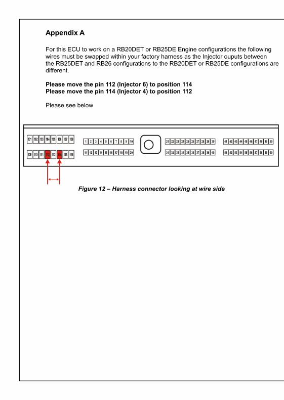
Appendix A
For this ECU to work on a RB20DET or RB25DE Engine configurations the following wires must be swapped within your factory harness as the Injector ouputs between the RB25DET and RB26 configurations to the RB20DET or RB25DE configurations are different.
Please move the pin 112 (Injector 6) to position 114Please move the pin 114 (Injector 4) to position 112
Please see below
Figure 12 – Harness connector looking at wire side
PLATINUM Pro Plug-in Nissan Skyline R32/R33 Quick Start Guide
Congratulations on purchasing a Haltech Engine Management System. This fully programmable Plug and Play product opens the door to virtually limitless performance modification and tuning of your vehicle. Programmable systems allow you to extract all the performance from your engine by delivering precisely the required amount of fuel and ignition timing that your engine requires for maximum output under all operating conditions.
This quick start guide will walk you through installation of the Platinum Pro ECU into a vehicle. This guide is accompanied by the full service manual located on the software CD provided with the ECU that you or your tuner will need to refer to before completing your installation and configuration. The Manual is included in the software which can be downloaded from the Haltech website www.haltech.com
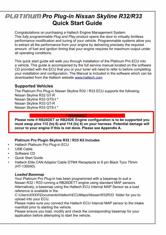
Supported VehiclesThe Platinum Pro Plug-in Nissan Skyline R32 / R33 ECU supports the following:Nissan Skyline R32 GT-RNissan Skyline R32 GTS-t *Nissan Skyline R33 GT-RNissan Skyline R33 GTS-t *
* WARNING! Please note if RB20DET or RB25DE Engine configuration is to be supported you must swap pins 112 (Inj 6) and 114 (Inj 4) on your harness. Potential damage will occur to your engine if this is not done. Please see Appendix A.
Platinum Pro Plugin Skyline R32 / R33 Kit Includes• Haltech Platinum Pro Plug-in ECU• USB Cable• Software CD• Quick Start Guide• Haltech Elite CAN Adaptor Cable DTM4 Receptacle to 8 pin Black Tyco 75mm
(HT-130040)
Loaded BasemapYour Platinum Pro Plug-in has been programmed with a basemap to suit a Nissan R32 / R33 running a RB26DETT engine using standard MAF sensors.Alternatively, a basemap using the Haltech ECU Internal MAP Sensor as a load reference is available in the C:\Users\XXXX\Documents\Haltech\ECUMaps\Nissan\R32R33 folder for you to upload into your ECU.Please make sure you connect the Haltech ECU Internal MAP sensor to the intake manifold prior to starting the vehicle.Please ensure you load, modify and check the corresponding basemap for yourapplication before attempting to start the vehicle.
ECU Installation
To install your new Platinum Pro Plug-in to your R32 / R33 Nissan Skyline, please follow the procedures below.
* Please Note the following Installation photos based on a Nissan Skyline R32 GT-R
You will require the following tools• Screwdrivers Phillips No 1 & No 2 , Small Flat• Socket set with 10mm socket• Cable Ties / 3M Velcro tape or similar
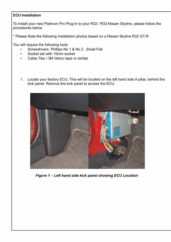
1. Locate your factory ECU. This will be located on the left hand side A pillar, behind the kick panel. Remove the kick panel to access the ECU.
Figure 1 – Left hand side kick panel showing ECU Location
ECU Pinout
Figure 11 – Platinum Pro Plugin R32 / R33 ECU Pinout
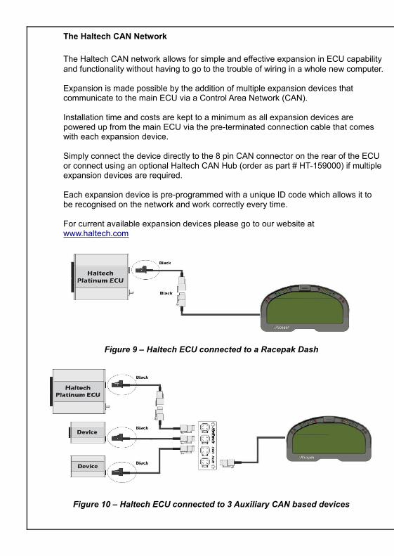
The Haltech CAN Network
The Haltech CAN network allows for simple and effective expansion in ECU capability and functionality without having to go to the trouble of wiring in a whole new computer.
Expansion is made possible by the addition of multiple expansion devices that communicate to the main ECU via a Control Area Network (CAN).
Installation time and costs are kept to a minimum as all expansion devices are powered up from the main ECU via the pre-terminated connection cable that comes with each expansion device.
Simply connect the device directly to the 8 pin CAN connector on the rear of the ECU or connect using an optional Haltech CAN Hub (order as part # HT-159000) if multiple expansion devices are required.
Each expansion device is pre-programmed with a unique ID code which allows it to be recognised on the network and work correctly every time.
For current available expansion devices please go to our website atwww.haltech.com
Figure 9 – Haltech ECU connected to a Racepak Dash
Figure 10 – Haltech ECU connected to 3 Auxiliary CAN based devices
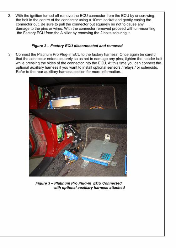
2. With the ignition turned off remove the ECU connector from the ECU by unscrewing the bolt in the centre of the connector using a 10mm socket and gently easing the connector out. Be sure to pull the connector out squarely so not to cause any damage to the pins or wires. With the connector removed proceed with un-mounting the Factory ECU from the A pillar by removing the 2 bolts securing it.
Figure 2 – Factory ECU disconnected and removed
3. Connect the Platinum Pro Plug-in ECU to the factory harness. Once again be careful that the connector enters squarely so as not to damage any pins, tighten the header boltwhile pressing the sides of the connector into the ECU. At this time you can connect the optional auxiliary harness if you want to install optional sensors / relays / or solenoids.Refer to the rear auxiliary harness section for more information.
Figure 3 – Platinum Pro Plug-in ECU Connected, with optional auxiliary harness attached
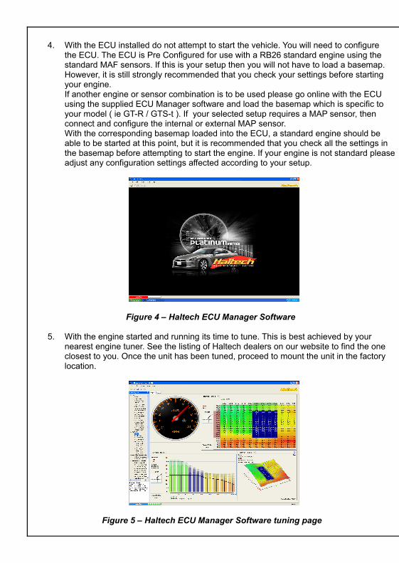
4. With the ECU installed do not attempt to start the vehicle. You will need to configure the ECU. The ECU is Pre Configured for use with a RB26 standard engine using the standard MAF sensors. If this is your setup then you will not have to load a basemap. However, it is still strongly recommended that you check your settings before starting your engine.If another engine or sensor combination is to be used please go online with the ECU using the supplied ECU Manager software and load the basemap which is specific to your model ( ie GT-R / GTS-t ). If your selected setup requires a MAP sensor, then connect and configure the internal or external MAP sensor.With the corresponding basemap loaded into the ECU, a standard engine should be able to be started at this point, but it is recommended that you check all the settings in the basemap before attempting to start the engine. If your engine is not standard please adjust any configuration settings affected according to your setup.
Figure 4 – Haltech ECU Manager Software
5. With the engine started and running its time to tune. This is best achieved by your nearest engine tuner. See the listing of Haltech dealers on our website to find the one closest to you. Once the unit has been tuned, proceed to mount the unit in the factory location.
Figure 5 – Haltech ECU Manager Software tuning page
Digital Pulsed Outputs ( DPO )
Digital Pulsed Outputs are capable of producing pulsed waveforms with varying duty and frequency. DPO's can be used to control various devices such as thermo-fans, shift lights, bypass air control valves, boost control solenoids etc. When a Digital Pulsed output is activated by the ECU the output will switch to ground. Solenoid valves and shift lights etc can be run directly from the output, however high current devices such as thermo-fans and additional fuel pumps must be activated through a relay. This way the DPO is only switching a relay and not a high current draw device.Two additional outputs can be connected using the Optional Rear Auxiliary Harness ( HT-040003 ) Digital Pulsed Outputs are limited to 800mA Max current draw.
Digital Switched Outputs ( DSO )
Digital Switched Outputs are capable of switching to groundDSO's can be used to control relays in an on / off state only.Two additional outputs can be connected using the Optional Rear Auxiliary Harness ( HT-040003 )Digital Switched Outputs are limited to 800mA Max current draw.
Analogue Voltage Inputs ( AVI )
Analogue Voltage Inputs accept variable voltage inputs from 0V to 5V. These inputscan also accept switch inputs that change between two different voltage levels. The On Voltage and Off Voltage define what the thresholds are between the On and Offstates. The Voltage can be viewed as a channel in the software to determine the thresholds for a switched input.Two additional sensors or switched inputs can be connected using the Optional Rear Auxiliary Harness ( HT-040003 )
Analogue Temperature Inputs ( ATI )
Analogue Temperature Inputs accept variable resistance sensors. These inputs have a pull – up resistor connected to them to allow them to be used withmost automotive temperature senders ( Variable resistance thermistor types ).Two additional sensors can be connected using the Optional Rear Auxiliary Harness ( HT-040003 )
Wire connections
When using crimp connectors ensure that the correct crimping tool is used – if indoubt do a pull test on a crimp connector, the wire should break before the wirepulls out of the crimp. Terminal soldering can weaken a connection and should onlybe used as a last resort. If solder joints are used, ensure joints are well isolatedfrom movement as solder joints are prone to fracture.When splicing 2 wires it is preferable to use a crimp splice – again if using a solderjoint, ensure joint is limited in its range of possible movement as solder joints areprone to fracture. Always use heat-shrink sleeving to insulate wires.
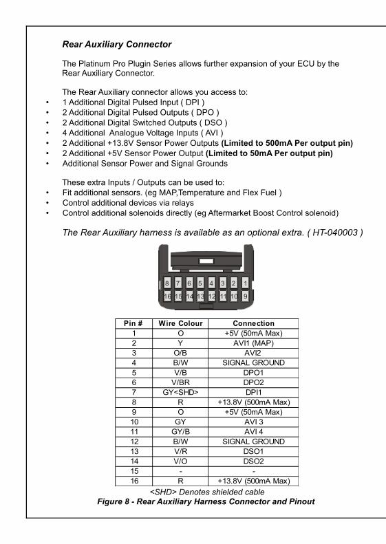
Rear Auxiliary Connector
The Platinum Pro Plugin Series allows further expansion of your ECU by theRear Auxiliary Connector.
The Rear Auxiliary connector allows you access to:• 1 Additional Digital Pulsed Input ( DPI )• 2 Additional Digital Pulsed Outputs ( DPO )• 2 Additional Digital Switched Outputs ( DSO )• 4 Additional Analogue Voltage Inputs ( AVI )• 2 Additional +13.8V Sensor Power Outputs (Limited to 500mA Per output pin)• 2 Additional +5V Sensor Power Output (Limited to 50mA Per output pin)• Additional Sensor Power and Signal Grounds
These extra Inputs / Outputs can be used to:• Fit additional sensors. (eg MAP,Temperature and Flex Fuel )• Control additional devices via relays• Control additional solenoids directly (eg Aftermarket Boost Control solenoid)
The Rear Auxiliary harness is available as an optional extra. ( HT-040003 )
<SHD> Denotes shielded cableFigure 8 - Rear Auxiliary Harness Connector and Pinout
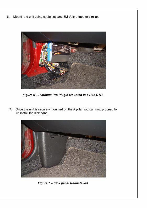
6. Mount the unit using cable ties and 3M Velcro tape or similar.
Figure 6 – Platinum Pro Plugin Mounted in a R32 GTR.
7. Once the unit is securely mounted on the A pillar you can now proceed to re-install the kick panel.
Figure 7 – Kick panel Re-installed
1234
9101112
5678
13141516
Looking into Back Of ConnectorPin # Wire Colour Connection1 O +5V (50mA Max)2 Y AVI1 (MAP)3 O/B AVI2 4 B/W SIGNAL GROUND5 V/B DPO16 V/BR DPO27 GY<SHD> DPI18 R +13.8V (500mA Max)9 O +5V (50mA Max)10 GY AVI 311 GY/B AVI 412 B/W SIGNAL GROUND13 V/R DSO114 V/O DSO215 - -16 R +13.8V (500mA Max)
ECU Manager Software
ECU Manager software is used for setup, calibration and diagnostics and canbe found on the CD supplied with this unit or downloaded from the Haltech website www.haltech.com
Minimum System Requirements
Operating System: Windows 2000 SP4 / XP / Vista / Windows 7Processor Speed: 1GHzRAM: 256 MbVideo Card: 128MB graphics card with 3D accelerationUSB: 1.1Hard Drive Space: 250MbMinimum Screen Resolution: 1024 x 768 pixels
Installing ECU Manager
Installing ECU Manager onto your PC is performed similar to any other Windows software package. Installation is outlined below to ensure correct installation:
1.Insert the CD-ROM into your PC’s CD-ROM drive. The CD should automatically launch into the Haltech Browser. If the CD does not run automatically double click on the “My Computer” icon on the desktop, double click on the Haltech icon (CD- ROM drive) to start the browser software.
2.The Browser will display the disclaimer and you will need to agree to the terms stated before allowing to progress. Read the Disclaimer and click on AGREE if you agree.
3.Now you will be able to access all the information contained on the CD
4.To download the Platinum Software, click on the Platinum Series ECU Manager Link. You will be prompted to install the software. Click “Install” to install ECU Manager and the Data Log viewer.
5. Follow the software prompts and install the software.
With your programming cable (USB) attached to your ECU and the other endconnected to your laptop, power up the ECU by turning your key to IGN. Start theprogramming software on your PC and go online with the ECU.
ECU Manager / ECU Manuals
Detailed manuals can be found in the software by pressing your F1 key or byselecting the Help tab located at the top left of the screen
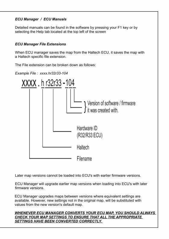
ECU Manager File Extensions
When ECU manager saves the map from the Haltech ECU, it saves the map witha Haltech specific file extension.
The File extension can be broken down as follows:
Example File : xxxx.hr32r33-104
Later map versions cannot be loaded into ECU's with earlier firmware versions.
ECU Manager will upgrade earlier map versions when loading into ECU's with later firmware versions.
ECU Manager upgrades maps between versions where equivalent settings are available. However, new settings not in the original map, will be substituted with values from the new version's default map.
WHENEVER ECU MANAGER CONVERTS YOUR ECU MAP, YOU SHOULD ALWAYS CHECK YOUR MAP SETTINGS TO ENSURE THAT ALL THE APPROPRIATE SETTINGS HAVE BEEN CONVERTED CORRECTLY.
ECU Manager Software
ECU Manager software is used for setup, calibration and diagnostics and canbe found on the CD supplied with this unit or downloaded from the Haltech website www.haltech.com
Minimum System Requirements
Operating System: Windows 2000 SP4 / XP / Vista / Windows 7Processor Speed: 1GHzRAM: 256 MbVideo Card: 128MB graphics card with 3D accelerationUSB: 1.1Hard Drive Space: 250MbMinimum Screen Resolution: 1024 x 768 pixels
Installing ECU Manager
Installing ECU Manager onto your PC is performed similar to any other Windows software package. Installation is outlined below to ensure correct installation:
1.Insert the CD-ROM into your PC’s CD-ROM drive. The CD should automatically launch into the Haltech Browser. If the CD does not run automatically double click on the “My Computer” icon on the desktop, double click on the Haltech icon (CD- ROM drive) to start the browser software.
2.The Browser will display the disclaimer and you will need to agree to the terms stated before allowing to progress. Read the Disclaimer and click on AGREE if you agree.
3.Now you will be able to access all the information contained on the CD
4.To download the Platinum Software, click on the Platinum Series ECU Manager Link. You will be prompted to install the software. Click “Install” to install ECU Manager and the Data Log viewer.
5. Follow the software prompts and install the software.
With your programming cable (USB) attached to your ECU and the other endconnected to your laptop, power up the ECU by turning your key to IGN. Start theprogramming software on your PC and go online with the ECU.
ECU Manager / ECU Manuals
Detailed manuals can be found in the software by pressing your F1 key or byselecting the Help tab located at the top left of the screen
ECU Manager File Extensions
When ECU manager saves the map from the Haltech ECU, it saves the map witha Haltech specific file extension.
The File extension can be broken down as follows:
Example File : xxxx.hr32r33-104
Later map versions cannot be loaded into ECU's with earlier firmware versions.
ECU Manager will upgrade earlier map versions when loading into ECU's with later firmware versions.
ECU Manager upgrades maps between versions where equivalent settings are available. However, new settings not in the original map, will be substituted with values from the new version's default map.
WHENEVER ECU MANAGER CONVERTS YOUR ECU MAP, YOU SHOULD ALWAYS CHECK YOUR MAP SETTINGS TO ENSURE THAT ALL THE APPROPRIATE SETTINGS HAVE BEEN CONVERTED CORRECTLY.
Rear Auxiliary Connector
The Platinum Pro Plugin Series allows further expansion of your ECU by theRear Auxiliary Connector.
The Rear Auxiliary connector allows you access to:• 1 Additional Digital Pulsed Input ( DPI )• 2 Additional Digital Pulsed Outputs ( DPO )• 2 Additional Digital Switched Outputs ( DSO )• 4 Additional Analogue Voltage Inputs ( AVI )• 2 Additional +13.8V Sensor Power Outputs (Limited to 500mA Per output pin)• 2 Additional +5V Sensor Power Output (Limited to 50mA Per output pin)• Additional Sensor Power and Signal Grounds
These extra Inputs / Outputs can be used to:• Fit additional sensors. (eg MAP,Temperature and Flex Fuel )• Control additional devices via relays• Control additional solenoids directly (eg Aftermarket Boost Control solenoid)
The Rear Auxiliary harness is available as an optional extra. ( HT-040003 )
<SHD> Denotes shielded cableFigure 8 - Rear Auxiliary Harness Connector and Pinout
6. Mount the unit using cable ties and 3M Velcro tape or similar.
Figure 6 – Platinum Pro Plugin Mounted in a R32 GTR.
7. Once the unit is securely mounted on the A pillar you can now proceed to re-install the kick panel.
Figure 7 – Kick panel Re-installed
1234
9101112
5678
13141516
Looking into Back Of ConnectorPin # Wire Colour Connection1 O +5V (50mA Max)2 Y AVI1 (MAP)3 O/B AVI2 4 B/W SIGNAL GROUND5 V/B DPO16 V/BR DPO27 GY<SHD> DPI18 R +13.8V (500mA Max)9 O +5V (50mA Max)10 GY AVI 311 GY/B AVI 412 B/W SIGNAL GROUND13 V/R DSO114 V/O DSO215 - -16 R +13.8V (500mA Max)
4. With the ECU installed do not attempt to start the vehicle. You will need to configure the ECU. The ECU is Pre Configured for use with a RB26 standard engine using the standard MAF sensors. If this is your setup then you will not have to load a basemap. However, it is still strongly recommended that you check your settings before starting your engine.If another engine or sensor combination is to be used please go online with the ECU using the supplied ECU Manager software and load the basemap which is specific to your model ( ie GT-R / GTS-t ). If your selected setup requires a MAP sensor, then connect and configure the internal or external MAP sensor.With the corresponding basemap loaded into the ECU, a standard engine should be able to be started at this point, but it is recommended that you check all the settings in the basemap before attempting to start the engine. If your engine is not standard please adjust any configuration settings affected according to your setup.
Figure 4 – Haltech ECU Manager Software
5. With the engine started and running its time to tune. This is best achieved by your nearest engine tuner. See the listing of Haltech dealers on our website to find the one closest to you. Once the unit has been tuned, proceed to mount the unit in the factory location.
Figure 5 – Haltech ECU Manager Software tuning page
Digital Pulsed Outputs ( DPO )
Digital Pulsed Outputs are capable of producing pulsed waveforms with varying duty and frequency. DPO's can be used to control various devices such as thermo-fans, shift lights, bypass air control valves, boost control solenoids etc. When a Digital Pulsed output is activated by the ECU the output will switch to ground. Solenoid valves and shift lights etc can be run directly from the output, however high current devices such as thermo-fans and additional fuel pumps must be activated through a relay. This way the DPO is only switching a relay and not a high current draw device.Two additional outputs can be connected using the Optional Rear Auxiliary Harness ( HT-040003 ) Digital Pulsed Outputs are limited to 800mA Max current draw.
Digital Switched Outputs ( DSO )
Digital Switched Outputs are capable of switching to groundDSO's can be used to control relays in an on / off state only.Two additional outputs can be connected using the Optional Rear Auxiliary Harness ( HT-040003 )Digital Switched Outputs are limited to 800mA Max current draw.
Analogue Voltage Inputs ( AVI )
Analogue Voltage Inputs accept variable voltage inputs from 0V to 5V. These inputscan also accept switch inputs that change between two different voltage levels. The On Voltage and Off Voltage define what the thresholds are between the On and Offstates. The Voltage can be viewed as a channel in the software to determine the thresholds for a switched input.Two additional sensors or switched inputs can be connected using the Optional Rear Auxiliary Harness ( HT-040003 )
Analogue Temperature Inputs ( ATI )
Analogue Temperature Inputs accept variable resistance sensors. These inputs have a pull – up resistor connected to them to allow them to be used withmost automotive temperature senders ( Variable resistance thermistor types ).Two additional sensors can be connected using the Optional Rear Auxiliary Harness ( HT-040003 )
Wire connections
When using crimp connectors ensure that the correct crimping tool is used – if indoubt do a pull test on a crimp connector, the wire should break before the wirepulls out of the crimp. Terminal soldering can weaken a connection and should onlybe used as a last resort. If solder joints are used, ensure joints are well isolatedfrom movement as solder joints are prone to fracture.When splicing 2 wires it is preferable to use a crimp splice – again if using a solderjoint, ensure joint is limited in its range of possible movement as solder joints areprone to fracture. Always use heat-shrink sleeving to insulate wires.
The Haltech CAN Network
The Haltech CAN network allows for simple and effective expansion in ECU capability and functionality without having to go to the trouble of wiring in a whole new computer.
Expansion is made possible by the addition of multiple expansion devices that communicate to the main ECU via a Control Area Network (CAN).
Installation time and costs are kept to a minimum as all expansion devices are powered up from the main ECU via the pre-terminated connection cable that comes with each expansion device.
Simply connect the device directly to the 8 pin CAN connector on the rear of the ECU or connect using an optional Haltech CAN Hub (order as part # HT-159000) if multiple expansion devices are required.
Each expansion device is pre-programmed with a unique ID code which allows it to be recognised on the network and work correctly every time.
For current available expansion devices please go to our website atwww.haltech.com
Figure 9 – Haltech ECU connected to a Racepak Dash
Figure 10 – Haltech ECU connected to 3 Auxiliary CAN based devices
2. With the ignition turned off remove the ECU connector from the ECU by unscrewing the bolt in the centre of the connector using a 10mm socket and gently easing the connector out. Be sure to pull the connector out squarely so not to cause any damage to the pins or wires. With the connector removed proceed with un-mounting the Factory ECU from the A pillar by removing the 2 bolts securing it.
Figure 2 – Factory ECU disconnected and removed
3. Connect the Platinum Pro Plug-in ECU to the factory harness. Once again be careful that the connector enters squarely so as not to damage any pins, tighten the header boltwhile pressing the sides of the connector into the ECU. At this time you can connect the optional auxiliary harness if you want to install optional sensors / relays / or solenoids.Refer to the rear auxiliary harness section for more information.
Figure 3 – Platinum Pro Plug-in ECU Connected, with optional auxiliary harness attached

ECU Installation
To install your new Platinum Pro Plug-in to your R32 / R33 Nissan Skyline, please follow the procedures below.
* Please Note the following Installation photos based on a Nissan Skyline R32 GT-R
You will require the following tools• Screwdrivers Phillips No 1 & No 2 , Small Flat• Socket set with 10mm socket• Cable Ties / 3M Velcro tape or similar
1. Locate your factory ECU. This will be located on the left hand side A pillar, behind the kick panel. Remove the kick panel to access the ECU.
Figure 1 – Left hand side kick panel showing ECU Location
ECU Pinout
Figure 11 – Platinum Pro Plugin R32 / R33 ECU Pinout
Appendix A
For this ECU to work on a RB20DET or RB25DE Engine configurations the following wires must be swapped within your factory harness as the Injector ouputs between the RB25DET and RB26 configurations to the RB20DET or RB25DE configurations are different.
Please move the pin 112 (Injector 6) to position 114Please move the pin 114 (Injector 4) to position 112
Please see below
Figure 12 – Harness connector looking at wire side
PLATINUM Pro Plug-in Nissan Skyline R32/R33 Quick Start Guide
Congratulations on purchasing a Haltech Engine Management System. This fully programmable Plug and Play product opens the door to virtually limitless performance modification and tuning of your vehicle. Programmable systems allow you to extract all the performance from your engine by delivering precisely the required amount of fuel and ignition timing that your engine requires for maximum output under all operating conditions.
This quick start guide will walk you through installation of the Platinum Pro ECU into a vehicle. This guide is accompanied by the full service manual located on the software CD provided with the ECU that you or your tuner will need to refer to before completing your installation and configuration. The Manual is included in the software which can be downloaded from the Haltech website www.haltech.com
Supported VehiclesThe Platinum Pro Plug-in Nissan Skyline R32 / R33 ECU supports the following:Nissan Skyline R32 GT-RNissan Skyline R32 GTS-t *Nissan Skyline R33 GT-RNissan Skyline R33 GTS-t *
* WARNING! Please note if RB20DET or RB25DE Engine configuration is to be supported you must swap pins 112 (Inj 6) and 114 (Inj 4) on your harness. Potential damage will occur to your engine if this is not done. Please see Appendix A.
Platinum Pro Plugin Skyline R32 / R33 Kit Includes• Haltech Platinum Pro Plug-in ECU• USB Cable• Software CD• Quick Start Guide• Haltech Elite CAN Adaptor Cable DTM4 Receptacle to 8 pin Black Tyco 75mm
(HT-130040)
Loaded BasemapYour Platinum Pro Plug-in has been programmed with a basemap to suit a Nissan R32 / R33 running a RB26DETT engine using standard MAF sensors.Alternatively, a basemap using the Haltech ECU Internal MAP Sensor as a load reference is available in the C:\Users\XXXX\Documents\Haltech\ECUMaps\Nissan\R32R33 folder for you to upload into your ECU.Please make sure you connect the Haltech ECU Internal MAP sensor to the intake manifold prior to starting the vehicle.Please ensure you load, modify and check the corresponding basemap for yourapplication before attempting to start the vehicle.

WARNING - HALTECH OFF-ROAD USAGE POLICY
It is unlawful to tamper with your vehicle's emissions equipment.Haltech products are designed and sold for sanctioned off-road/competition non-emissions controlledvehicles only. Using Haltech products for street/road use on public roads is prohibited by law. It is theresponsibility of the installer and/or user of this product to ensure compliance with all applicable local andfederal laws and regulations. Please check with your local vehicle authority before using any Haltechproduct
INSTALLATION OF HALTECH PRODUCTS
No responsibility whatsoever is accepted by Haltech for the fitment of Haltech Products. The onus is clearlyon the installer to ensure that both their knowledge and the parts selected are correct for that particularapplication. Any damage to parts or consequential damage or costs resulting from the incorrect installationof Haltech products are totally the responsibility of the installer.
Always disconnect the battery when doing electrical work on your vehicle. Avoid sparks, open flames oruse of electrical devices near flammable substances. Do not run the engine with a battery chargerconnected as this could damage the ECU and other electrical equipment. Do not overcharge the battery orreverse the polarity of the battery or any charging unit. Disconnect the Haltech ECU from the electricalsystem whenever doing any welding on the vehicle by unplugging the wiring harness connector from theECU. After completing the ECU installation, make sure there is no wiring left un-insulated. Uninsulatedwiring can cause sparks, short circuits and in some cases fire. Before attempting to run the engine ensurethere are no leaks in the fuel system. All fuel system components and wiring should be mounted awayfrom heat sources, shielded if necessary and well ventilated. Always ensure that you follow workshopsafety procedures. If you're working underneath a jacked-up car, always use safety stands!
HALTECH LIMITED WARRANTY
Unless specified otherwise, Haltech warrants its products to be free from defects in material orworkmanship for a period of 12 months from the date of purchase, valid in the original country ofpurchase only. Proof of purchase, in the form of a bill of sale or receipted invoice, which indicates that theproduct is within the warranty period, must be presented to obtain warranty service. Haltech suggests thatthe purchaser retain the dealer's dated bill of sale/receipt as evidence of the date of retail purchase. If theHaltech product is found to be defective as mentioned above, it will be replaced or repaired if returnedprepaid along with proof of purchase. This shall constitute the sole liability of Haltech. To the extentpermitted by law, the foregoing is exclusive and in lieu of all other warranties or representations, eitherexpressed or implied, including any implied warranty of merchantability or fitness. In no event shallHaltech be liable for special or consequential damages.
PRODUCT RETURNS
Please include a copy of the original purchase invoice along with the unused, undamaged product and itsoriginal packaging. Any product returned with missing accessory items or packaging will incur extracharges to return the item to a re-saleable condition. All product returns must be sent via a freightmethod with adequate tracking, insurance and proof of delivery services. Haltech will not be heldresponsible for product returns lost during transit. The sale of any sensor or accessory that is supplied insealed packaging is strictly non-refundable if the sealed packaging has been opened or tampered with.This will be clearly noted on the product packaging. If you do not accept these terms please return thesensor in its original unopened packaging within 30 days for a full refund.
Returning a sensor or accessory product within 30 days of purchase: Product may be returned for credit orfull refund. (Any sealed packaging must not have been opened or tampered with)
Returning a sensor or accessory product after 30 days of purchase: Product may be returned for creditonly (no refunds given) and is subject to a 10% Restocking fee. (Any sealed packaging must not havebeen opened or tampered with)
V1.2
Notes

V11.0
PLATINUM PRO PLUG-IN
Nissan Skyline R32 / R33(HT-055101)
QUICK START GUIDE