pm gearless traction - · pdf filepm gearless traction machine ... drive the cabin through the...
TRANSCRIPT
PM GEARLESS TRACTION
MACHINE USERS MANUAL
Thank you for choosing our gearless traction machine.
-Please read this manual carefully before using the product.
-Wrong operation may cause reduction of machine lifetime, property loss or casualties.
-Please keep this manual well.
CONTENTS
Foreword
Page 1
Page 2 Features and Working Principle
Working Condition of Traction Machine Page 3
Product and Parameter Page 3
Dimension Drawing of G Series Machine
Page 4
Dimension Drawing of K Series Machine Page 11
Dimension Drawing of P Series Machine Page 15
Transportation, Storage and Installation Page 20
Cautions before Usage Page 20
Traction Machine Installation Instruction
Page 21
Electrical Connection Page 21
Installation and Usage of Barring Device
Installation and Usage of Release Device
Page 24
Maintenance of Traction Machine
Page 25
Page 26
Installation and Adjustment of Drum Brake
Installation and Adjustment of Block Brake
Installation and Adjustment of Disk Brake
Instruction of Sin-Cos Encoder
Faults and Solutions
Page 28
Page 30
Page 31
Page 32
Page 33
PM GEARLESS TRACTION MACHINE USERS MANUAL
Only qualified personnel who must be trained for the job and must be familiar with
the installation, assembly, commissioning and operation of the product are
authorized to perform any planning, installation or maintenance work and this
must be done in accordance with the relevant instructions such as EN81.1 (Safety
rules for the construction and installation of lifts).
We do not accept any warranty or liability claim for personal injury, property
loss and product quality problem caused by improper operation.
Foreword
Wrong operation may cause property loss or injuries.
Thank you for choosing our gearless traction machine.
Please read this manual carefully before use this product. Wrong operation may
cause reduction of machine lifetime, property loss or casualties. Any operation
must refer to this manual.
In addition, any emend of this manual will not be notified.
General Safety Instructions
There are two safety attention grades in this manual.
Please read this manual carefully before transportation, installation,
connection, maintenance and know well with the safety instructions.
Wrong operation may cause property loss or casualties.
! Danger
! Caution
! Danger
PM GEARLESS TRACTION MACHINE USERS MANUAL
Page 1
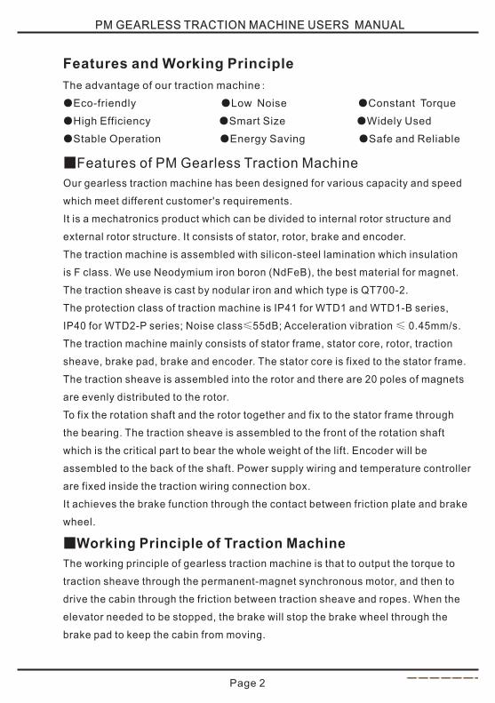
Features and Working Principle
■Features of PM Gearless Traction Machine
Our gearless traction machine has been designed for various capacity and speed
which meet different customer's requirements.
It is a mechatronics product which can be divided to internal rotor structure and
external rotor structure. It consists of stator, rotor, brake and encoder.
The traction machine is assembled with silicon-steel lamination which insulation
is F class. We use Neodymium iron boron (NdFeB), the best material for magnet.
The traction sheave is cast by nodular iron and which type is QT700-2.
The protection class of traction machine is IP41 for WTD1 and WTD1-B series,
IP40 for WTD2-P series; Noise class≤55dB; Acceleration vibration ≤ 0.45mm/s.
The traction machine mainly consists of stator frame, stator core, rotor, traction
sheave, brake pad, brake and encoder. The stator core is fixed to the stator frame.
The traction sheave is assembled into the rotor and there are 20 poles of magnets
are evenly distributed to the rotor.
To fix the rotation shaft and the rotor together and fix to the stator frame through
the bearing. The traction sheave is assembled to the front of the rotation shaft
which is the critical part to bear the whole weight of the lift. Encoder will be
assembled to the back of the shaft. Power supply wiring and temperature controller
are fixed inside the traction wiring connection box.
It achieves the brake function through the contact between friction plate and brake
wheel.
The working principle of gearless traction machine is that to output the torque to
traction sheave through the permanent-magnet synchronous motor, and then to
drive the cabin through the friction between traction sheave and ropes. When the
elevator needed to be stopped, the brake will stop the brake wheel through the
brake pad to keep the cabin from moving.
■Working Principle of Traction Machine
The advantage of our traction machine:
●Eco-friendly ●Low Noise ●Constant Torque
●High Efficiency ●Smart Size ●Widely Used
●Stable Operation ●Energy Saving ●Safe and Reliable
Page 2
PM GEARLESS TRACTION MACHINE USERS MANUAL
Page 3
Product and Parameter
Please contact our sales personnel or read the traction machines nameplate
for the relevant model number and technical parameter.
! CautionTo make sure machines must be used under below working conditions.
●The height above sea level no more than 2000 meters.
●Working temperature 5~40℃, relative humidity under 90%.
●Deviation between supply voltage fluctuation and rated voltage should within±7%.
●No corrosive, flammable and explosive gas in the working environment.
●Ropes and traction sheave grooves must keep clean.
●Wrap angle and counter weight must meet the requirement of rules 9.3.1 of EN81.1.
●Traction machine power should be supplied by control system and its rated
parameter should be subjected to the machines nameplate. Do not supply the
power to the traction machine directly in case machines damage.
PM GEARLESS TRACTION MACHINE USERS MANUAL
Working Condition of Traction Machine
We do not accept any compensation for machines damage caused by
not use the machines under the above working condition requirements.
PM GEARLESS TRACTION MACHINE USERS MANUAL
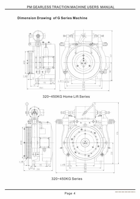
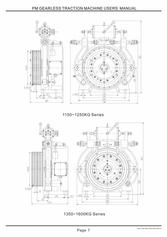
Dimension Drawing of G Series Machine
320~450KG Home Lift Series
Page 4
320~450KG Series
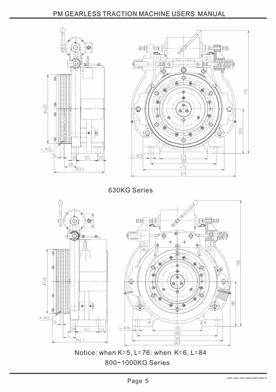
800~1000KG Series
Notice: when K=5, L=76;when K=6, L=84
PM GEARLESS TRACTION MACHINE USERS MANUAL
Page 5
630KG Series
PM GEARLESS TRACTION MACHINE USERS MANUAL
Page 6
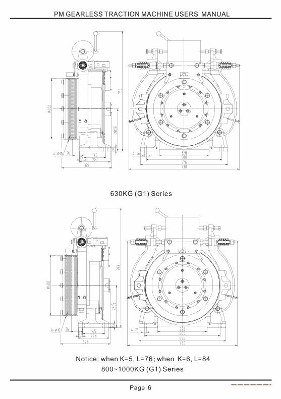
800~1000KG (G1) Series
Notice: when K=5, L=76;when K=6, L=84
630KG (G1) Series
PM GEARLESS TRACTION MACHINE USERS MANUAL
Page 7
1150~1250KG Series
1350~1600KG Series
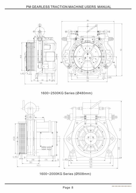
PM GEARLESS TRACTION MACHINE USERS MANUAL
Page 8
1600~2500KG Series (Ø480mm)
1600~2000KG Series (Ø508mm)
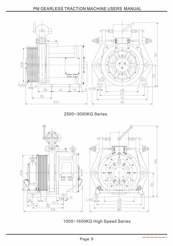
PM GEARLESS TRACTION MACHINE USERS MANUAL
Page 9
2500~3000KG Series
1000~1600KG High Speed Series
PM GEARLESS TRACTION MACHINE USERS MANUAL
Page 10
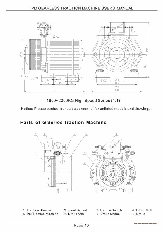
1600~2000KG High Speed Series (1:1)
Parts of G Series Traction Machine
1. Traction Sheave 2.Hand Wheel 3.Handle Switch 4.Lifting Bolt 5.PM Traction Machine 6.Brake Arm 7. Brake Shoes 8. Brake
Notice: Please contact our sales personnel for unlisted models and drawings.
PM GEARLESS TRACTION MACHINE USERS MANUAL
Page 11
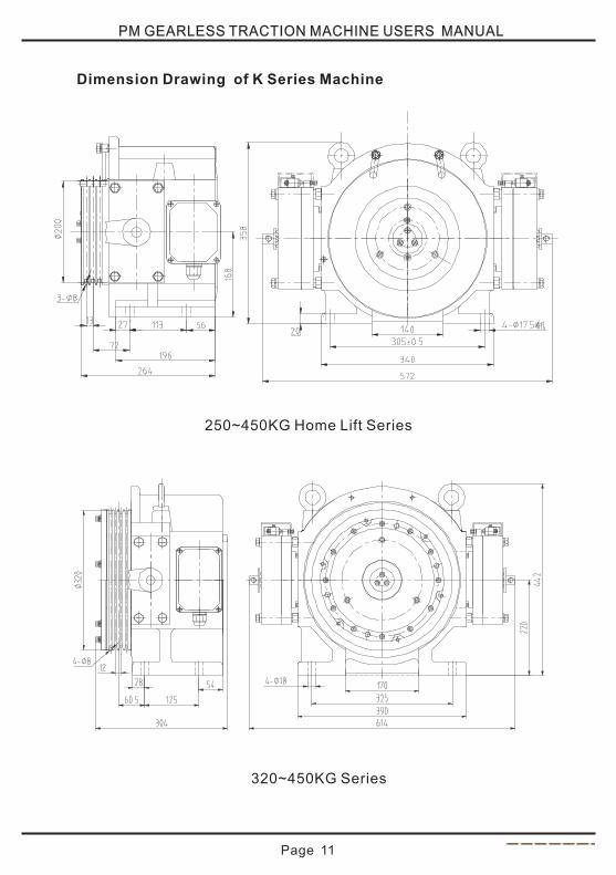
Dimension Drawing of K Series Machine
250~450KG Home Lift Series
320~450KG Series
PM GEARLESS TRACTION MACHINE USERS MANUAL
Page 12
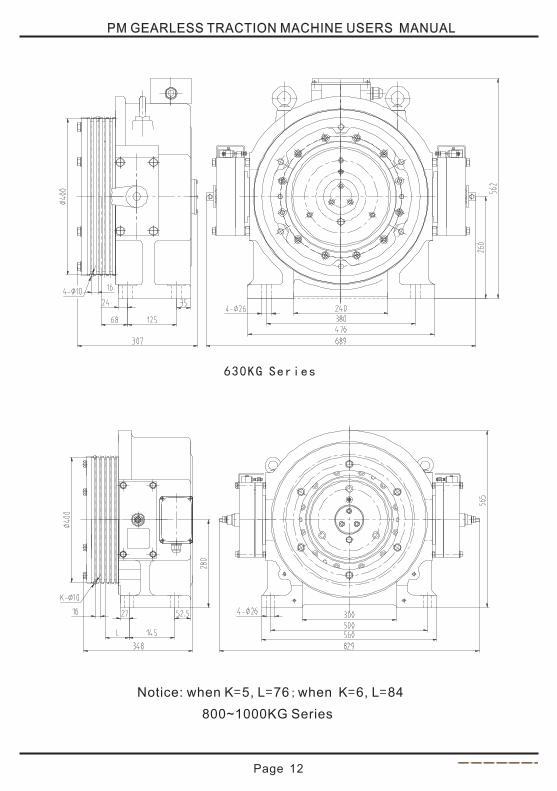
630KG Series
800~1000KG Series
Notice: when K=5, L=76;when K=6, L=84
PM GEARLESS TRACTION MACHINE USERS MANUAL
Page 13
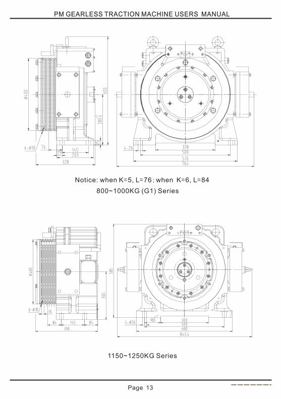
800~1000KG (G1) Series
Notice: when K=5, L=76;when K=6, L=84
1150~1250KG Series
PM GEARLESS TRACTION MACHINE USERS MANUAL
Page 14
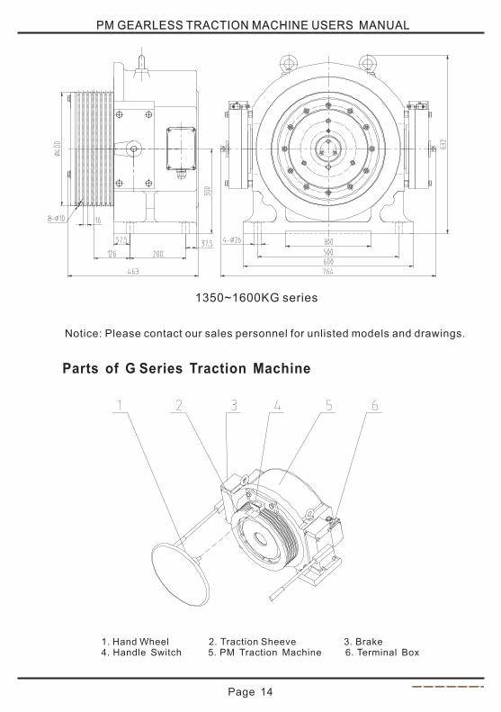
Parts of G Series Traction Machine
1350~1600KG series
1. Hand Wheel 2.Traction Sheeve 3.Brake 4.Handle Switch 5.PM Traction Machine 6.Terminal Box
Notice: Please contact our sales personnel for unlisted models and drawings.
PM GEARLESS TRACTION MACHINE USERS MANUAL
Page 15
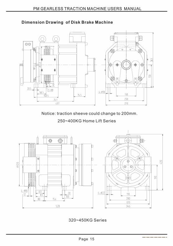
Dimension Drawing of Disk Brake Machine
Notice: traction sheeve could change to 200mm.
250~400KG Home Lift Series
320~450KG Series
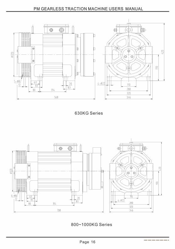
630KG Series
800~1000KG Series
PM GEARLESS TRACTION MACHINE USERS MANUAL
Page 16
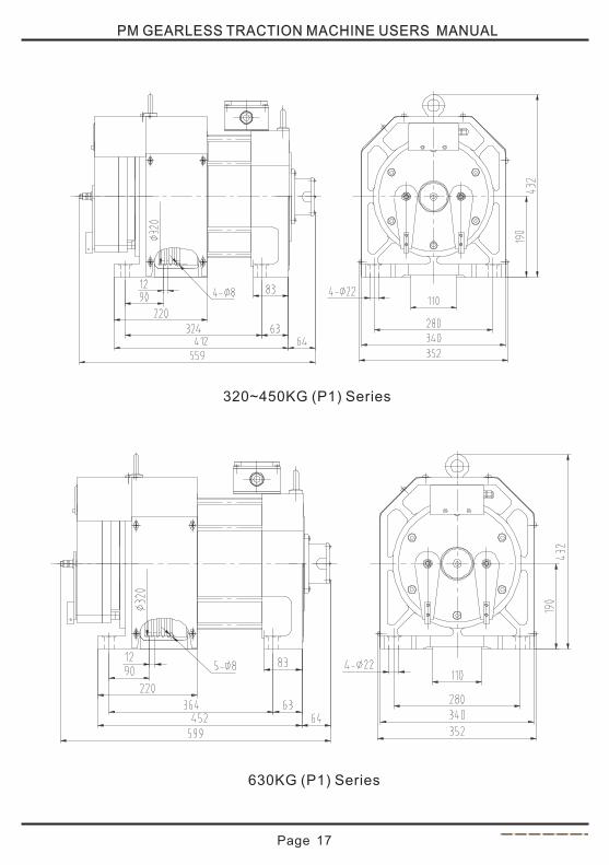
320~450KG (P1) Series
630KG (P1) Series
PM GEARLESS TRACTION MACHINE USERS MANUAL
Page 17
PM GEARLESS TRACTION MACHINE USERS MANUAL
Page 18
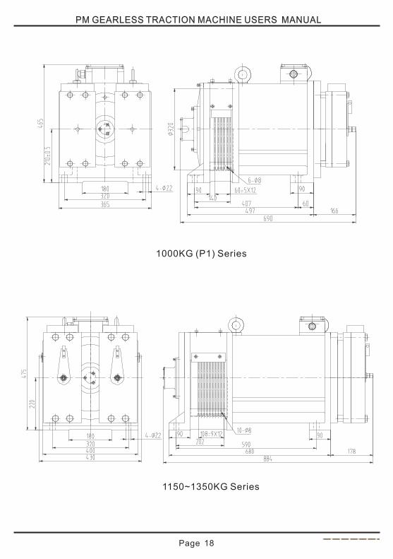
1000KG (P1) Series
1150~1350KG Series
PM GEARLESS TRACTION MACHINE USERS MANUAL
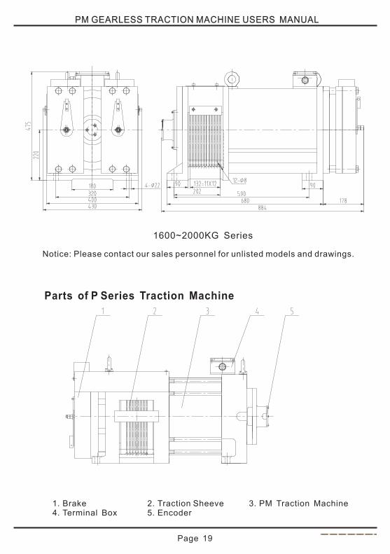
Page 19
Parts of P Series Traction Machine
1.Brake 2.Traction Sheeve 3.PM Traction Machine 4.Terminal Box 5.Encoder
Notice: Please contact our sales personnel for unlisted models and drawings.
1600~2000KG Series
PM GEARLESS TRACTION MACHINE USERS MANUAL
Page 20
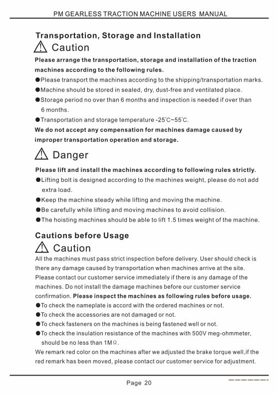
Transportation, Storage and Installation
Please arrange the transportation, storage and installation of the traction
machines according to the following rules.
Please transport the machines according to the shipping/transportation marks.
Machine should be stored in sealed, dry, dust-free and ventilated place.
Storage period no over than 6 months and inspection is needed if over than
6 months.
Transportation and storage temperature -25℃~55℃.
We do not accept any compensation for machines damage caused by
improper transportation operation and storage.
●
●
●
●
Please lift and install the machines according to following rules strictly.
Lifting bolt is designed according to the machines weight, please do not add
extra load.
Keep the machine steady while lifting and moving the machine.
Be carefully while lifting and moving machines to avoid collision.
The hoisting machines should be able to lift 1.5 times weight of the machine.
●
●
●
●
Cautions before Usage
All the machines must pass strict inspection before delivery. User should check is
there any damage caused by transportation when machines arrive at the site.
Please contact our customer service immediately if there is any damage of the
machines. Do not install the damage machines before our customer service
confirmation. Please inspect the machines as following rules before usage.
To check the nameplate is accord with the ordered machines or not.
To check the accessories are not damaged or not.
To check fasteners on the machines is being fastened well or not.
To check the insulation resistance of the machines with 500V meg-ohmmeter,
should be no less than 1MΩ.
We remark red color on the machines after we adjusted the brake torque well,if the
red remark has been moved, please contact our customer service for adjustment.
●
●
●
●
! Caution
! Danger
! Caution
PM GEARLESS TRACTION MACHINE USERS MANUAL
Page 21
Traction Machine Installation Instructions
Please check and calculate the carrying capacity of the machines frame and
groundwork to make sure that can bear the load of the working traction machine.
The machines frame should be strong enough to carry the weight. The groundwork
should be flat and flatness no over than 0.1mm.
Please install the traction machines according to the following rules.
Use four screws (strength grade no less than 12.9) to install machines on the frame.
Adjust the distance of ropes-prevent pole and ropes are no more than 1.5mm
after ropes are hanged to the sheave.
Traction machines must be installed according to EN81.1 requirement.
Traction machines should work in a ventilation environment.
Traction machines should work in the environment according to the relevant
requirements of protection class.
●
●
●
●
●
Electrical Connection
The electrical connection may only be made by a qualified electrician.
All electrical connection must be done according to the following rules.
Keep the connection box clean and dry.
The connection terminals (wires) should be provided by our company.
Make sure there is no short circuit of all the electrical parts.
Make sure the terminals, connector and bolts are fastened.
Please cover the connection box after finished electrical connection.
●
●
●
●
●
1. Electrical Connection Instruction
! Danger
! Danger
PM GEARLESS TRACTION MACHINE USERS MANUAL
Page 22
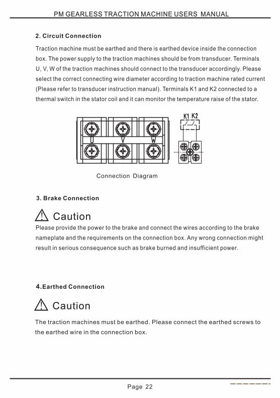
2. Circuit Connection
Traction machine must be earthed and there is earthed device inside the connection
box. The power supply to the traction machines should be from transducer. Terminals
U, V, W of the traction machines should connect to the transducer accordingly. Please
select the correct connecting wire diameter according to traction machine rated current
(Please refer to transducer instruction manual). Terminals K1 and K2 connected to a
thermal switch in the stator coil and it can monitor the temperature raise of the stator.
Connection Diagram
3. Brake Connection
Please provide the power to the brake and connect the wires according to the brake
nameplate and the requirements on the connection box. Any wrong connection might
result in serious consequence such as brake burned and insufficient power.
! Caution
4.Earthed Connection
The traction machines must be earthed. Please connect the earthed screws to
the earthed wire in the connection box.
! Caution
PM GEARLESS TRACTION MACHINE USERS MANUAL
Page 23
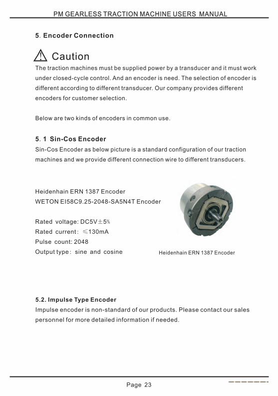
5.Encoder Connection
The traction machines must be supplied power by a transducer and it must work
under closed-cycle control. And an encoder is need. The selection of encoder is
different according to different transducer. Our company provides different
encoders for customer selection.
Below are two kinds of encoders in common use.
. Sin-Cos Encoder
Sin-Cos Encoder as below picture is a standard configuration of our traction
machines and we provide different connection wire to different transducers.
5 1
Heidenhain ERN 1387 Encoder
Heidenhain ERN 1387 Encoder
Rated voltage: DC5V±5%
Rated current: ≤130mA
Pulse count: 2048
Output type: sine and cosine
WETON EI58C9.25-2048-SA5N4T Encoder
5.2. Impulse Type Encoder
Impulse encoder is non-standard of our products. Please contact our sales
personnel for more detailed information if needed.
! Caution
PM GEARLESS TRACTION MACHINE USERS MANUAL
Page 24
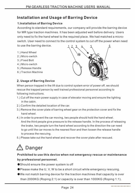
Installation and Usage of Barring Device
1.Installation of Barring Device
According to standard requirements, our company will provide the barring device
for MR type traction machines. It has been adjusted well before delivery. Users
only need to fix the hand wheel to the required place. We had matched a micro-
switch. User need to connect to the control system to cut off the power when need
to use the barring device.
1.) Hand Wheel
2.) Micro-switch
3.) Fixed Bolt
4.) Micro-switch
5.) Release Handle
6.) Traction Machine
Usage of Barring Device2.
When person trapped in the lift due to control system error of power off, we should
rescue the trapped person by well trained professional personnel according to
following instructions.
1.) Cut off the main power supply in case of elevator moving and ensure the lighting
in the cabin.
2.) Confirm the detailed location of the car.
3.) Remove the cover plate of barring wheel gear on the protection cover and fix the
hand wheel.
4.) In order to prevent the car moving, two people should hold the hand wheel.
And the third people give pressure to the release handle. In the process of releasing
the brake, two people turn the hand wheel according to the direction the car need
to go until the car moves to the nearest floor and then loosen the release handle
to process the rescuing.
5.) Please take out the hand wheel and recover the cover plate after rescued.
! Danger
Prohibited to use this device when not emergency rescue or maintenance
by professional personnel.
●Should ensure the power system is off
●Please make the U, V, W to be a short circuit while emergency rescuing.
●We not match barring device for the traction machines that capacity is over
than 2000KG (Roping 2:1) or capacity is over than 1000KG (Roping 1:1).
PM GEARLESS TRACTION MACHINE USERS MANUAL
Installation and Usage of Release Device
Our company will provide the release device for MRL type traction machines. It has been
adjusted well before delivery and users do not need to adjust. Users can choose the release
cable length according to its project situation.
Please follow the below instructions while used need to install the release device.
1) To ensure there is no twisting, knotting and quarter turn which might affect the release cable
torque while installing the release device. If the cable needs to be turn, we suggest the
minimum bending radius of the cable is not less than 400mm.
2) Adequate space is needed when install the brake release holder. To avoid the release cable
bending radius is too small. Should ensure the release cable is at the place that the bending
radius is not less than 200mm, otherwise it will difficult or even not able to achieve release
function.
3) Release device can not be too stressed which is better to achieve releasing but not affect
the traction machines brake torque function. Or it will counterbalance the brake torque
which leads to the brake lose efficiency.
4) Please keep the brake release holder out of unprofessional people.
1.Installation of Release Device
1.Usage of Release Device
When person trapped in the lift due to power off, we should rescue the trapped
person by well trained professional personnel according to following instructions.
1). Cut off the main power supply in case of elevator moving.
2). onfirm the detailed location of the car.
3). Demount thumbscrew on the remote release device.
4). Pull down the release handle and turn the release handle. When the brake works,
and then turn the traction sheave to rescue.
5). After release operation finished, please lock the thumbscrew again.
6). If the release function is no good, please work on the screw (M6) to adjust the tighten
to achieve releasing.
Ensure the lighting in the cabin and c
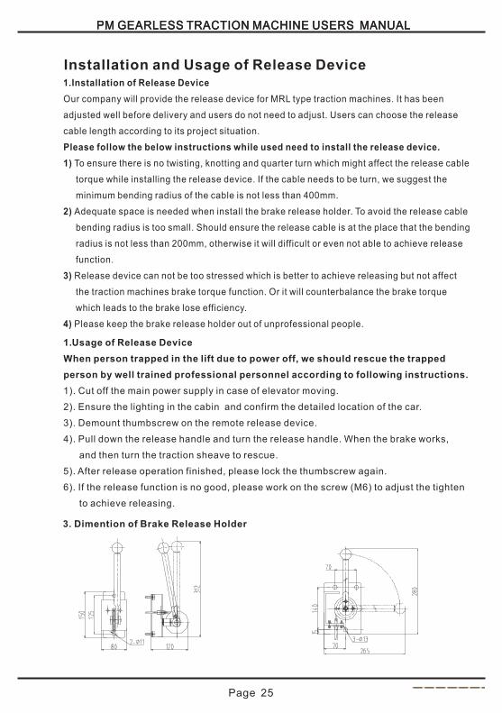
3 Dimention of Brake Release Holder
.
PM GEARLESS TRACTION MACHINE USERS MANUAL
Page 25
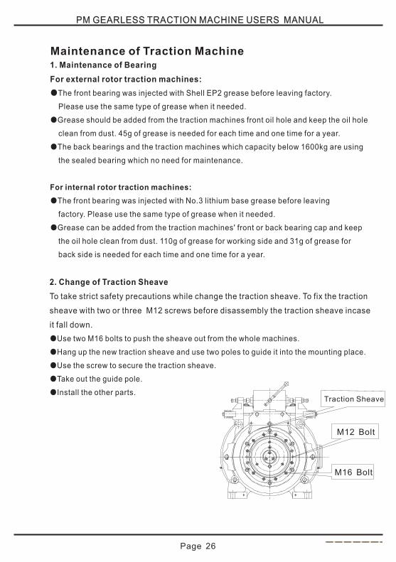
Traction Sheave
M12 Bolt
PM GEARLESS TRACTION MACHINE USERS MANUAL
Page 26
1. Maintenance of Bearing
For external rotor traction machines:
The front bearing was injected with Shell EP2 grease before leaving factory.
Please use the same type of grease when it needed.
Grease should be added from the traction machines front oil hole and keep the oil hole
clean from dust. 45g of grease is needed for each time and one time for a year.
The back bearings and the traction machines which capacity below 1600kg are using
the sealed bearing which no need for maintenance.
●
●
●
For internal rotor traction machines:
●The front bearing was injected with No.3 lithium base grease before leaving
factory. Please use the same type of grease when it needed.
●Grease can be added from the traction machines' front or back bearing cap and keep
the oil hole clean from dust. 110g of grease for working side and 31g of grease for
back side is needed for each time and one time for a year.
Maintenance of Traction Machine
2. Change of Traction Sheave
To take strict safety precautions while change the traction sheave. To fix the traction
sheave with two or three M12 screws before disassembly the traction sheave incase
it fall down.
Use two M16 bolts to push the sheave out from the whole machines.
Hang up the new traction sheave and use two poles to guide it into the mounting place.
Use the screw to secure the traction sheave.
Take out the guide pole.
Install the other parts.
●
●
●
●
●
M16 Bolt
PM GEARLESS TRACTION MACHINE USERS MANUAL
Page 27
3. Short Circuit of Traction Machine
To make short circuit with U, V, W terminals when the gearless traction stop running
is to avoid the traction machines start to run again while do maintenance. It make
the elevator is more safe and being stop in a reliable way. In order to avoid the
machines damage caused by short circuit in fast time, please follow the below
instruction if needed.
The output connector of the transducer and short circuit connector are separated
and delay the connection if needed. When the elevator is running at high speed, the
safety circuit is turn off or the electric power is suddenly off without emergency
source, the traction machines will reduce its speed through the brake start to work.
After delay, the short circuit connector will work. This will avoid the serious damage
to the machines and ensure the safety of elevator.
Our company does not accept any compensation for machines damage caused
by wrong operation of short circuit.
4. Maintenance Instruction
Keep the machines working environment clean and dry;
Keep the traction machines clean;
Pay attention to the reliability and abrasion of the braking system.
●
●
●
Installation and Adjustment of Drum Brake
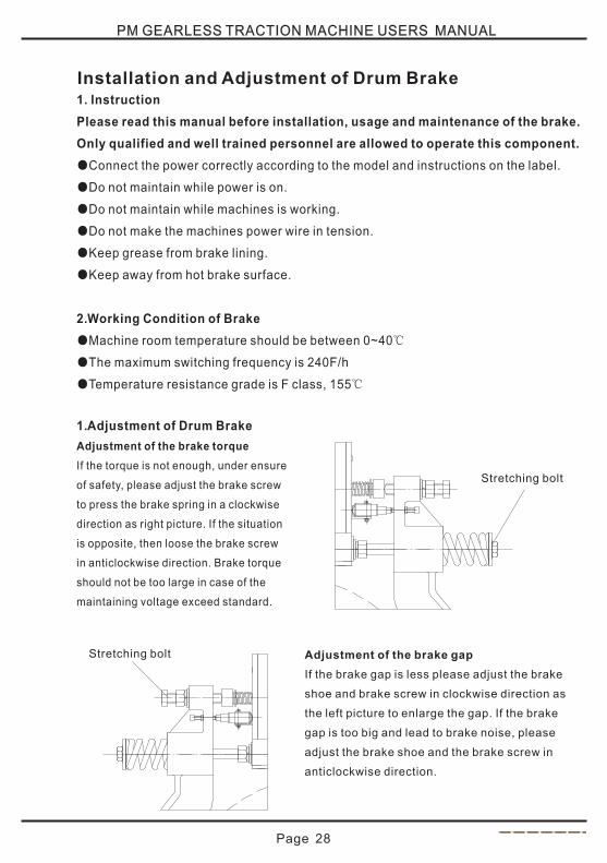
Adjustment of the brake gap
If the brake gap is less please adjust the brake
shoe and brake screw in clockwise direction as
the left picture to enlarge the gap. If the brake
gap is too big and lead to brake noise, please
adjust the brake shoe and the brake screw in
anticlockwise direction.
制动力调整螺杆
制动瓦间隙调整螺杆
PM GEARLESS TRACTION MACHINE USERS MANUAL
Page 28
1. Instruction
Please read this manual before installation, usage and maintenance of the brake.
Only qualified and well trained personnel are allowed to operate this component.
Connect the power correctly according to the model and instructions on the label.
Do not maintain while power is on.
Do not maintain while machines is working.
Do not make the machines power wire in tension.
Keep grease from brake lining.
Keep away from hot brake surface.
2.Working Condition of Brake
Machine room temperature should be between 0~40℃
The maximum switching frequency is 240F/h
Temperature resistance grade is F class, 155℃
1.Adjustment of Drum Brake
Adjustment of the brake torque
If the torque is not enough, under ensure
of safety, please adjust the brake screw
to press the brake spring in a clockwise
direction as right picture. If the situation
is opposite, then loose the brake screw
in anticlockwise direction. Brake torque
should not be too large in case of the
maintaining voltage exceed standard.
●
●
●
●
●
●
●
●
●
Stretching boltStretching bolt
Stretching bolt
制动瓦微调螺钉
PM GEARLESS TRACTION MACHINE USERS MANUAL
page 29
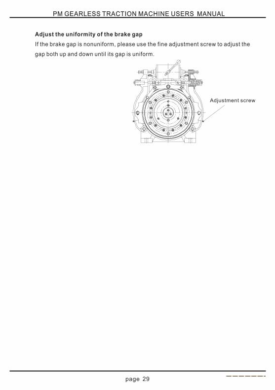
Adjust the uniformity of the brake gap
If the brake gap is nonuniform, please use the fine adjustment screw to adjust the
gap both up and down until its gap is uniform.
Adjustment screw
Page 30
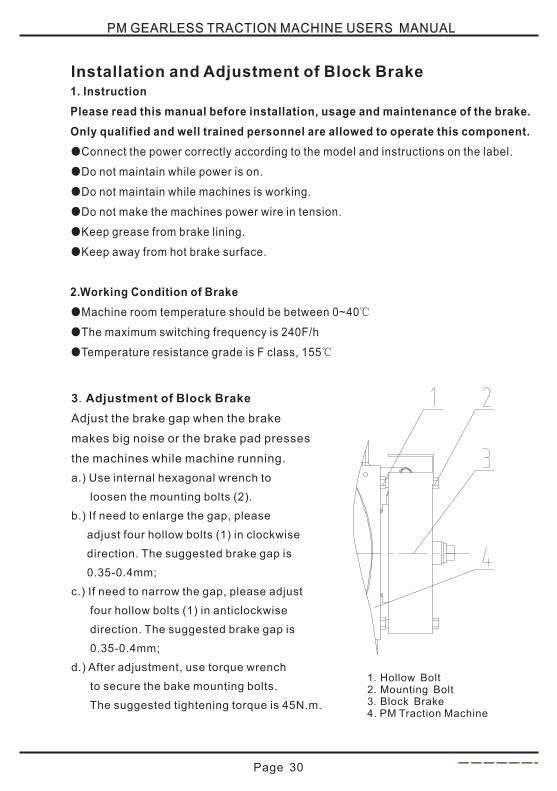
3.Adjustment of Block Brake
Adjust the brake gap when the brake
makes big noise or the brake pad presses
the machines while machine running.
a.) Use internal hexagonal wrench to
loosen the mounting bolts (2).
b.) If need to enlarge the gap, please
adjust four hollow bolts (1) in clockwise
direction. The suggested brake gap is
0.35-0.4mm;
c.) If need to narrow the gap, please adjust
four hollow bolts (1) in anticlockwise
direction. The suggested brake gap is
0.35-0.4mm;
d.) After adjustment, use torque wrench
to secure the bake mounting bolts.
The suggested tightening torque is 45N.m.
Installation and Adjustment of Block Brake1. Instruction
Please read this manual before installation, usage and maintenance of the brake.
Only qualified and well trained personnel are allowed to operate this component.
Connect the power correctly according to the model and instructions on the label.
Do not maintain while power is on.
Do not maintain while machines is working.
Do not make the machines power wire in tension.
Keep grease from brake lining.
Keep away from hot brake surface.
2.Working Condition of Brake
Machine room temperature should be between 0~40℃
The maximum switching frequency is 240F/h
Temperature resistance grade is F class, 155℃
●
●
●
●
●
●
●
●
●
1.Hollow Bolt 2.Mounting Bolt 3.Block Brake 4. PM Traction Machine
PM GEARLESS TRACTION MACHINE USERS MANUAL
Page 31
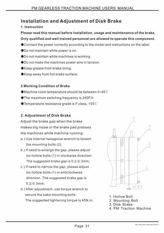
Installation and Adjustment of Disk Brake1. Instruction
Please read this manual before installation, usage and maintenance of the brake.
Only qualified and well trained personnel are allowed to operate this component.
Connect the power correctly according to the model and instructions on the label.
Do not maintain while power is on.
Do not maintain while machines is working.
Do not make the machines power wire in tension.
Keep grease from brake lining.
Keep away from hot brake surface.
2.Working Condition of Brake
Machine room temperature should be between 0~40℃
The maximum switching frequency is 240F/h
Temperature resistance grade is F class, 155℃
●
●
●
●
●
●
●
●
●
3. Adjustment of Disk Brake
Adjust the brake gap when the brake
makes big noise or the brake pad presses
the machines while machine running.
a.) Use internal hexagonal wrench to loosen
the mounting bolts (2).
b.) If need to enlarge the gap, please adjust
six hollow bolts (1) in clockwise direction.
The suggested brake gap is 0.2-0.3mm;
c.) If need to narrow the gap, please adjust
six hollow bolts (1) in anticlockwise
direction. The suggested brake gap is
0.2-0.3mm;
d.) After adjustment, use torque wrench to
secure the bake mounting bolts.
The suggested tightening torque is 45N.m.
1.Hollow Bolt 2.Mounting Bolt 3.Disk Brake 4.PM Traction Machine
PM GEARLESS TRACTION MACHINE USERS MANUAL

Page 32
PM GEARLESS TRACTION MACHINE USERS MANUAL
1.Tools
Torque Spanner M10 Bolt Wrist Strap Clean Duster
2.Notice of Installation
Wear the wrist strap and static-free shoes before operation;
Keep the encoder from shaking and collision. Do not knock on the encoder with
hammer or screwdriver.
Please do not pull the encoder cable in a rude way in case of the encoder cable
damage.
3.Instruction of Installation
Clean the encoder connecting part and the mounting hole on the traction machine.
Make sure the tension sleeve is unstuck.
Loosen the back cover bolts and dismount it.
Install the encoder to the traction machine encoder mounting hole and use M5X50
hexagon socket screw to fix the encoder. Suggest torque is 5N.m.
Make sure the encoder can turn smoothly, if not, please check and install again if
needed. After confirm it can be turn smoothly, please fix the tension sleeve with
the torque spanner. Suggest torque is 1.05~1.25N.m.
Connect the encoder cable and mount the encoder back cover.
4.Disassembly of Encoder
Loosen the M2.5X5 bolt of tension sleeve.
Loosen the back cover bolts and dismount it.
Loosen the M5X50 bolt and keep M10 hole with 2~3 thread.
Use M10 bolt to push the M5X50 bolt until the encoder has been pull out.
● ● ● ●
●
●
●
●
●
●
●
●
●
●
●
●
●
Instruction of Sin-Cos Encoder
Page 33
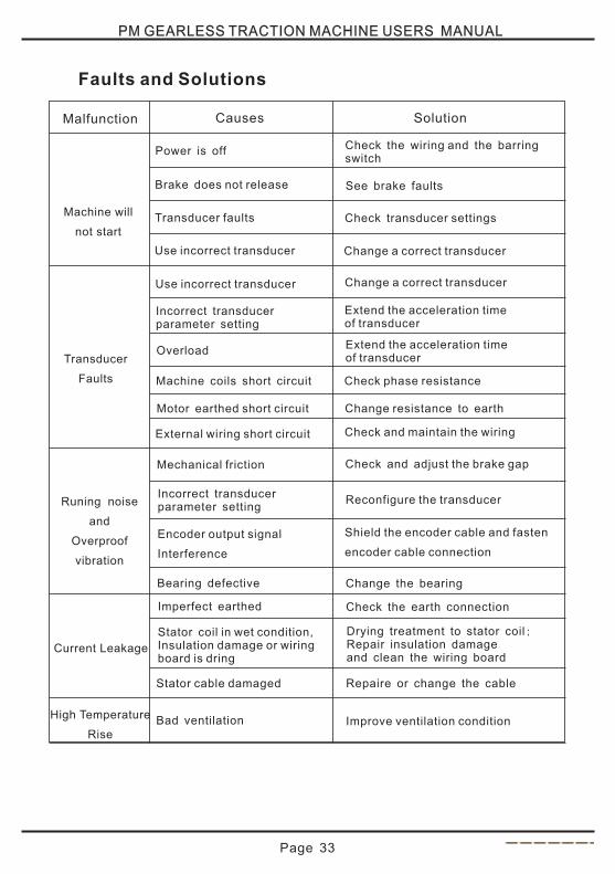
Malfunction
Machine will
not start
Causes
Transducer faults
Incorrect transducerparameter setting
Overload
Machine coils short circuit
Motor earthed short circuit
External wiring short circuit
Imperfect earthed
Stator coil in wet condition,Insulation damage or wiringboard is dring
Stator cable damaged
Bad ventilation
Mechanical friction
Encoder output signal
Interference
Brake does not release
Power is off
Solution
Check transducer settings
Change a correct transducer
Extend the acceleration time of transducer
Check phase resistance
Change resistance to earth
Check and maintain the wiring
Change the bearing
Check the earth connection
Drying treatment to stator coil;Repair insulation damageand clean the wiring board
Repaire or change the cable
Improve ventilation condition
Check and adjust the brake gap
Reconfigure the transducer
Shield the encoder cable and fasten
encoder cable connection
See brake faults
Check the wiring and the barring switch
Transducer
Faults
Runing noise
and
Overproof
vibration
Current Leakage
High Temperature
Rise
Bearing defective
PM GEARLESS TRACTION MACHINE USERS MANUAL
Faults and Solutions
Use incorrect transducer
Use incorrect transducer Change a correct transducer
Extend the acceleration time of transducer
Incorrect transducerparameter setting