point i/o 24v dc expansion power supply - plccenter.cn · point i/o 24v dc expansion power supply...
TRANSCRIPT

Installation Instruction
POINT I/O 24V dc Expansion Power Supply
(Cat. No. 1734-EP24DC Series B)
The 1734-EP24DC expansion power unit passes 24V dc field power to the I/O modules to the right of it. This unit extends the backplane bus power for up to 12 I/O modules to the right of the supply, and creates a new field voltage partition segment for driving field devices.
Description Description
1 1734-EP24DC Power Supply Module
4 DIN Rail Locking Screw (orange)
2 Interlocking side pieces 5 RTB Removal Handle
3 Module label 6 Removable Terminal Block (RTB)
1
6
54
3
2
POINT I/O is a trademark of Rockwell AutomationPublication 1734-IN058A-EN-P - August 2000

2 POINT I/O 24V dc Expansion Power Supply
The expansion power supply also separates field power from I/O modules to the left of the unit, effectively providing functional and logical partitioning for:
• separating field power between input and output modules
• separating field power to the analog and digital modules
• grouping modules to perform a specific task or function
Its dark-gray color allows for easy visual inspection and identification.
You can use multiple expansion power units with the POINT I/O adapters to assemble a full system. For instance, if you are using the 1734-ADN adapter, you may use a 1734-EP24DC expansion power unit to add additional modules in 12 module increments. For example, if you had a 36 module system with a 1734 POINT I/O adapter, you would have two 1734-EP24DC expansion power units to provide more PointBus current for modules to the right of the supply.
.
ATTENTION
!Do not connect 120/240V ac to the 1734-EP24DC terminals. Damage to the supply will result.
ATTENTION
!You can only use the 1734-EP24DC expansion power unit with the 1734 POINT I/O adapters, such as the 1734-ADN DeviceNet adapter.
Publication 1734-IN058A-EN-P - August 2000

POINT I/O 24V dc Expansion Power Supply 3
Installing the 1734-EP24DC Expansion Power SupplyTo install the EP24DC on the DIN rail, proceed as follows.
1. Position the EP24DC vertically above the DIN rail.
2. Engage the interlocking side pieces with the unit on the left.
3. Press down firmly to install the EP24DC on the DIN rail.
4. The locking mechanism will lock the EP24DC to the DIN rail.
To remove an EP24DC from the DIN rail
1. To remove the EP24DC from the DIN rail, pull up on the RTB removal handle (5) to remove the terminal block.
2. Remove the module to the right of the EP24DC from its base unit.
3. Use a small bladed screwdriver to rotate the DIN rail locking screw (4) to a vertical position.
4. This releases the locking mechanism. Then lift straight up to remove.
If installing a replacement EP24DC to an existing system
1. Remove the module to the right of the EP24DC from its base unit.
2. Position the EP24DC (1) vertically above the DIN rail.
3. Slide the EP24DC down allowing the interlocking side pieces to engage the adjacent modules (both left and right sides).
4. Press firmly to seat the EP24DC (1) on the DIN rail. The EP24DC locking mechanism will snap into place.
5. Reinsert the module into the base next to the EP24DC.
Publication 1734-IN058A-EN-P - August 2000

4 POINT I/O 24V dc Expansion Power Supply
European Communities (EC) Directive ComplianceIf this product has the CE mark it is approved for installation within the European Union and EEA regions. It has been designed and tested to meet the following directives.
EMC Directive
This product is tested to meet the Council Directive 89/336/EC Electromagnetic Compatibility (EMC) by applying the following standards, in whole or in part, documented in a technical construction file:
• EN 50081-2 EMC — Generic Emission Standard, Part 2 — Industrial Environment
• EN 50082-2 EMC — Generic Immunity Standard, Part 2 — Industrial Environment
This product is intended for use in an industrial environment.
Low Voltage Directive
This product is tested to meet Council Directive 73/23/EEC Low Voltage, by applying the safety requirements of EN 61131-2 Programmable Controllers, Part 2 - Equipment Requirements and Tests. For specific information required by EN 61131-2, see the appropriate sections in this publication, as well as the Allen-Bradley publication Industrial Automation Wiring and Grounding Guidelines, publication 1770-4.1.
Open style devices must be provided with environmental and safety protection by proper mounting in enclosures designed for specific application conditions. See NEMA Standards publication 250 and IEC publication 529, as applicable, for explanations of the degrees of protection provided by different types of enclosures.
Publication 1734-IN058A-EN-P - August 2000

POINT I/O 24V dc Expansion Power Supply 5
Wiring the Expansion Power Supply
41970
C
V
NC
C
V
NC
NC = No ConnectionCHAS GND = Chassis GroundC = CommonV = Supply
CHASGND
CHASGND
SystemPower
FieldPower
1734-EP24DC
Publication 1734-IN058A-EN-P - August 2000

6 POINT I/O 24V dc Expansion Power Supply
12/24v dc Wiring
Connect Terminal Terminals (for continuing power)
+V dc 6 7
-V dc 4 5
Chas Gnd 2 3
12/24V dc becomes the internal power bus for modules to the right.
ATTENTION
!Use the 1734-EP24DC expansion power supply only with Adapter Class products.
NC NC
C
V V
C
V dc
V = 12/24V dc, C = CommonCHAS GND = Chassis ground
This dc supply will be connected to the internal power bus.
12/24V dc
CHASGND
CHASGND
3
5
7
0 1
2
4
6
Do not connect 120/240V ac power to this supply.
EP24
Publication 1734-IN058A-EN-P - August 2000

POINT I/O 24V dc Expansion Power Supply 7
Example of continuing power
IMPORTANT The 1734-EP24DC expansion power supply can only be used with POINT I/O adapters.
0 1 0 1 0 1 0 1 0 1 0 1 0 1 0 1
AdapterStatus
DeviceNetStatus
PointBusStatus
1734-ADN
DeviceNetPower
SystemPower
1734-EP24DC
DeviceNetPower
SystemPower
EP24DCADN
Example of continued power.12/24V dc only 1734adn4
IB2
IB4
OB2E
OB4E
IE2C
IE2C
OE2C
Publication 1734-IN058A-EN-P - August 2000
8 POINT I/O 24V dc Expansion Power Supply
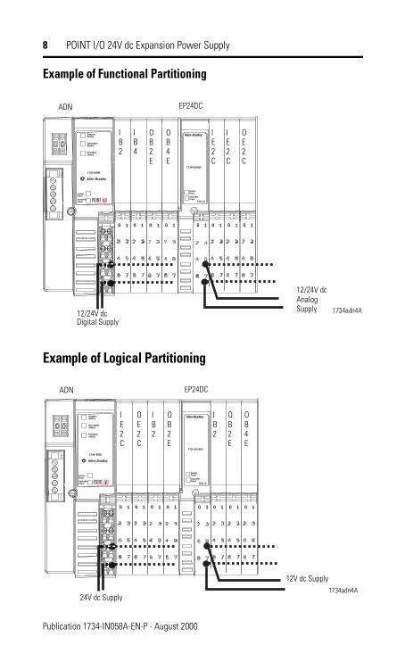
Example of Functional Partitioning
Example of Logical Partitioning
0 1 0 1 0 1 0 1 0 1 0 1 0 1 0 1
AdapterStatus
DeviceNetStatus
PointBusStatus
1734-ADN
DeviceNetPower
SystemPower
1734-EP24DC
DeviceNetPower
SystemPower
EP24DCADN
12/24V dcDigital Supply
1734adn4A
IB2
IB4
OB2E
OB4E
IE2C
IE2C
OE2C
12/24V dc Analog Supply
0 1 0 1 0 1 0 1 0 1 0 1 0 1 0 1
AdapterStatus
DeviceNetStatus
PointBusStatus
1734-ADN
DeviceNetPower
SystemPower
1734-EP24DC
DeviceNetPower
SystemPower
EP24DCADN
24V dc Supply1734adn4A
IB2
OB2E
OB4E
IE2C
OE2C
12V dc Supply
IB2
OB2E
Publication 1734-IN058A-EN-P - August 2000

POINT I/O 24V dc Expansion Power Supply 9
Safety Approval
C-UL and UL Hazardous Location Approval Approbation d’utilisation dans des environnements dangereux par la C-UL/UL
C-UL and UL certifies products for general use as well as for use in hazardous locations. Actual C-UL and UL certification is indicated by the product label as shown below, and not by statements in any user documentation.
La C-UL/UL certifie des produits pour une utilisation générale aussi bien que pour une utilisation en environnements dangereux. La certification C-UL/UL en vigueur est indiquée par l'étiquette produit et non par des indications dans la documentation utilisateur.
Example of the C-UL and UL certification product label:
Exemple d'étiquette de certification d'un produit par la C-UL/UL :
To comply with C-UL and UL certification for use in hazardous locations, the following information becomes a part of the product literature for this C-UL and UL-certified industrial control product.
• This equipment is suitable for use in Class I, Division 2, Groups A, B, C, D, or non-hazardous locations only.
• The products having the appropriate C-UL and UL markings (that is, Class I, Division 2, Groups A, B, C, D) are certified for use in other equipment where the suitability of combination (that is, application or use) is determined by the C-UL and UL or the local inspection office having jurisdiction
Pour satisfaire à la certification C-UL/UL en environnements dangereux, les informations suivantes font partie intégrante de la documentation des produits de commande industrielle certifiés.
• Cet équipement ne convient qu’à une utilisation en environnements de Classe I, Division 2, Groupes A, B, C, D ou non dangereux.
• Les produits portant le marquage C-UL/UL approprié (c'est-à-dire Classe I, Division 2, Groupes A, B, C, D) sont certifiés pour une utilisation avec d'autres équipements, les combinaisons d’applications et d’utilisations étant déterminées par la C-UL/UL ou le bureau local d'inspection qualifié.
Important: Due to the modular nature of a programmable control system, the product with the highest temperature rating determines the overall temperature code rating of a programmable control system in a Class I, Division 2, location. The temperature code rating is marked on the product label as shown.
Important: De par la nature modulaire des systèmes de commande programmables, le produit ayant le code de température le plus élevé détermine le code de température global du système dans un environnement de Classe I, Division 2. Le code de température est indiqué sur l'étiquette produit.
:
The following warnings apply to products having C-UL and UL certification for use in hazardous locations.
Les avertissements suivants s'appliquent aux produits ayant la certification C-UL/UL pour une utilisation en environnements dangereux.
WARNING: Explosion Hazard• Substitution of components may impair suitability for
Class I, Division 2.• Do not replace components unless power has been
switched off or the area is known to be non-hazardous.• Do not disconnect equipment unless power has been
switched off or the area is known to be non-hazardous.• Do not disconnect connectors unless power has been
switched off or the area is known to be non-hazardous. Secure any user-supplied connectors that mate to external circuits on this equipment by using screws, sliding latches, threaded connectors, or other means such that any connection can withstand a 15 Newton (3.4 lb.) separating force applied for a minimum of one minute.
AVERTISSEMENT : Risque d’explosion • La substitution de composants peut rendre ce matériel inadapté à
une utilisation en environnements de Classe I, Division 2.
• Couper le courant ou s'assurer que l’environnement est classé non dangereux avant de remplacer des composants.
• Couper le courant ou s’assurer que l’environnement est classé non dangereux avant de débrancher l'équipement.
• Couper le courant ou s'assurer que l’environnement est classé non dangereux avant de débrancher les connecteurs. Fixer tous les connecteurs fournis par l'utilisateur pour se brancher aux circuits externes de cet équipement à l 'aide de vis, loquets coulissants, connecteurs filetés ou autres, de sorte que les connexions résistent à une force de séparation de 15 Newtons (1,5 kg - 3,4 lb.) appliquée pendant au moins une minute.
• S'assurer que l'environnement est classé non dangereux avant de changer les piles.
C-UL and UL logo is a registered trademark of the Underwriters Laboratories.
Les sigles C-UL et UL sont des marques déposées de la Underwriters Laboratories.
C US
CL I, DIV 2GP A,B,C,D
TEMP
LISTED
C US
CL I, DIV 2GP A,B,C,D
TEMP
LISTED
CL I, DIV 2GP A,B,C,D
TEMP
Look for temperature code rating here.
C US
LISTEDTemperature code rating:CL I, DIV 2GP A,B,C,D
TEMPC US
LISTEDCode de température :
Le code de température est indiqué ici.
Publication 1734-IN058A-EN-P - August 2000

10 POINT I/O 24V dc Expansion Power Supply
SpecificationsSpecifications - 1734-EP24DC Power Supply ModuleI/O Module Capacity 12 modulesPower Supply Note: In order to comply with CE Low Voltage
Directives (LVD), you must use a Safety Extra Low Voltage (SELV) or a Protected Extra Low Voltage (PELV) power supply to power this adapter.
Input Voltage Rating 24V dc nominal10-28.8V dc range
Field Side Power Requirements 24V dc (+20% = 28.8V dc maximum) @ 400mA maximum
Inrush Current 6A maximum for 10msIndicators 1 Green Field Power Status Indicator
1 Green 5V System Power IndicatorPointBus Output Current Horizontal mounting -
1A at 10-19.2V input; 1.3A at 19.2-28.8V inputVertical mounting - 1A at 10-28.8V input
Input Overvoltage Protection Reverse polarity protectedInterruption Output voltage will stay within specifications
when input drops out for 10ms at 10V with maximum load.
Module Location Between I/O modules in 1734 systemBreaks field power bus
Limitations Use with POINT I/O Adapters onlyGeneral SpecificationsPower Consumption 9.8W maximum @ 28.8V dcPower Dissipation 3.0W maximum @ 28.8V dcThermal Dissipation 10.0 BTU/hr maximum @ 28.8V dcIsolation Voltage 1250V rms/V acField Power Bus
Supply VoltageVoltage Range
24V dc nominal10-28.8V dc range
Dimensions Inches (Millimeters)
3.00H x 1.00W x 5.25L(76.2H x 25.4W x 133.4L)
Specifications continued on next page.
Publication 1734-IN058A-EN-P - August 2000

POINT I/O 24V dc Expansion Power Supply 11
Current Derating for Mounting
Environmental ConditionsOperational TemperatureStorage TemperatureRelative HumidityShock Operating
Non-operatingVibration
-20 to 55°C (-4 to 131°F)-40 to 85°C (-40 to 185°F)5 to 95% noncondensing12g peak acceleration, 11(±1)ms pulse width50g peak acceleration, 11(±1)ms pulse widthTested 2g @ 10-500Hz per IEC 68-2-6
Conductors Wire Size
Category
14AWG (2.5mm2) - 22AWG (0.25mm2) solid or stranded wire rated at 75°C or greater3/64 inch (1.2mm) insulation maximum21
Terminal Base Screw Torque 7 pound-inches (0.6Nm)Field Wiring Terminations 0 - No Connection 1 - No Connection
2 - Chassis Ground 3 - Chassis Ground4 - Common 5 - Common6 - Supply Voltage 7 - Supply Voltage
Mass 4.38 oz/12.42 gramsAgency Certification (when product is marked)
C-UL ListedC-UL Class I, Division 2, Groups A, B, C and D certifiedUL ListedCE marked for all applicable directives.C-Tick marked for all applicable acts.DeviceNet compatible as certified by ODVA, Inc.
1 Use this conductor category information for planning conductor routing as described in publication 1770-4.1, “Industrial Automation Wiring and Grounding Guidelines.”
1.3
1.0
0.5 Horizontal - 1A @ (10-19.2V); 1.3A @ (19.2-28.8)Vertical - 1A @ (10-28.8V)
10 19.2 28.8
Voltage
Current
Publication 1734-IN058A-EN-P - August 2000

Publication 1734-IN058A-EN-P - August 2000 PN 957345-84© 2000 Rockwell International Corporation. Printed in USA