porous debris behavior modeling of quench-02, quench-03
TRANSCRIPT
International Conference
Nuclear Energy for New Europe 2006 Portorož, Slovenia, September 18-21, 2006
http://www.djs.si/port2006
813.1
Porous Debris Behavior Modeling of QUENCH-02, QUENCH-03 and QUENCH-09 Experiments
Arcadii E. Kisselev, Gennadii V.Kobelev, Valerii F.Strizhov Nuclear Safety Institute(IBRAE) of Russian Academy of Sciences
B.Tulskaya 52, 115191 Moscow, Russia [email protected], kgv@ ibrae.ac.ru, [email protected]
Alexander D. Vasiliev Nuclear Safety Institute(IBRAE) of Russian Academy of Sciences
B.Tulskaya 52, 115191 Moscow, Russia [email protected]
ABSTRACT
The heat-up, melting, relocation, hydrogen generation phenomena, relevant for high-temperature stages both in a reactor case and small-scale integral tests like QUENCH, are governed in particular by heat and mass transfer in porous debris and molten pools which are formed in the core region.
Porous debris formation and behavior in QUENCH experiments (QUENCH-02, QUENCH-03, QUENCH-09) plays a considerable role and its adequate modeling is important for thermal analysis. In particular, the analysis of QUENCH experiments shows that the major hydrogen release takes place in debris and melt regions formed in the upper part of the fuel assembly.
The porous debris model was implemented in the Russian best estimate numerical code RATEG/SVECHA/HEFEST developed for modelling thermal hydraulics and severe accident phenomena in a reactor.
The original approach for debris evolution is developed in the model from classical principles using a set of parameters including debris porosity; average particle diameter; temperatures and mass fractions of solid, liquid and gas phases; specific interface areas between different phases; effective thermal conductivity of each phase, including radiative heat conductivity; mass and energy fluxes through the interfaces. The debris model is based on the system of continuity, momentum and energy conservation equations, which consider the dynamics of volume-averaged velocities and temperatures of fluid, solid and gaseous phases of porous debris.
The model is used for calculation of QUENCH experiments. The results obtained by the model are compared to experimental data concerning different aspects of thermal behavior: thermal hydraulics of porous debris, radiative heat transfer in a porous medium, the generalized melting and refreezing behavior of materials, hydrogen production.
1 INTRODUCTION
The heat-up, melting, relocation and hydrogen generation phenomena, relevant for high-temperature stages both in a reactor case and small-scale integral tests like QUENCH [1], are governed in particular by heat and mass transfer in porous debris and molten pools which are

813.2
formed in the core region. The rods eventually lose their mechanical holding and collapse into heaps of particles named “porous debris bed”. The accurate modelling of its behavior is very important for adequate description of dynamics.
The analysis of TMI-2 accident [2] and the results of integral out-of-pile (CORA [3], QUENCH [1]) and in-pile experiments (PHEBUS [4], PBF [5]) have shown that before the water succeeds in cooling the fuel pins there will be an enhanced oxidation of the zircaloy cladding that in turn causes a sharp increase in temperature, hydrogen production and fission product release.
The new concepts which are now used in the development of best-estimate computer codes include the detailed self-consistent modelling of wide spectrum of physical phenomena typical of late stage of severe accident. This is why the adequate calculation of porous debris behavior is now a very important part of severe accident analysis using best-estimate computer codes.
Porous debris models will allow more realistic physical modeling of the core degradation, and move the sophistication of the thermal evaluations more parallel to other processes simulations. This is an incremental improvement to a code customized to thermal-hydraulic and severe fuel damage evaluations.
Beside that, porous debris module should ensure: • sufficient accuracy of the debris heat and mass transfer problem’s solution when the
extent of detailed description of core and in-vessel structures is given by external thermal hydraulic code;
• high computational speed and stability of running in the integral code designed for severe accident description;
• some universality which would allow to apply the module to different types of reactors and to different nodalizations within the bounds of one type of reactor.
Unfortunately, the physical processes taking place during the late phase of severe accidents are very complicated and rather far from complete understanding. The main phenomena important for adequate description of debris behavior are as following: debris formation, coolant flow through debris and corresponding heat transfer, mass and energy transfer in debris, phase transitions and chemical reactions, decay and chemical heat generation, convective and radiative heat transfer, solid crust formation and disappearance on region boundaries.
It is assumed that new metallic surfaces are formed by cracking and fragmentation of the oxygen-embrittled cladding tubes as a result of the thermal shock during flooding leading to enhanced oxidation and hydrogen generation.
Cladding melt relocation occurred laterally and axially within the confinement of the scale by which the surface area is diminishing and the thermal contact to the pellets is improving [1]. This contributes to the development of large temperature variations. Together with the embrittlement of bare scale (without contact to metallic cladding but in contact with the steam) this can result in scale cracking and triggering of internal oxidation and outward melt penetration, which will accelerate the steam oxidation. The analysis of QUENCH-02, QUENCH-03 and QUENCH-09 experiments shows that the major hydrogen release took place in debris and melt regions formed in the upper part of the fuel assembly.
The factors which complicate the problem are eutectics formations between interacting materials typical of reactor technology (UO2, ZrO2, Zr, Fe, Cr, Ni, B4C) and a lack of thermo-physical data for high temperature region (in the course of an accident, the temperature reaches the value 3100K and higher).
The degradation is non-homogeneous and the core exhibits, at the same time, both damaged and undamaged regions. The important part of porous debris numerical analysis is the modelling of radiative heat transfer in the debris and between debris and non-debris
Proceedings of the International Conference Nuclear Energy for New Europe, 2006
813.3
(initial geometry) meshes. Some approaches are used in the literature to describe the radiative heat transfer in the core [13,14].
Heat and mass transfer in porous media have been investigated intensively during the last two decades due to their extremely wide applications including not only nuclear engineering but also geothermal energy, oil industry, pollutant migration in waters, different types of heat exchangers, thermal isolation in buildings and tubes etc. [6-8]. A detailed review of the subject of flow in porous media has been recently done by Pop and Ingham [9].
The debris models have been implemented into known severe accident codes such as RELAP/SCDAP [10], MELCOR [11] and CATHARE/ICARE [12].
The basic differences between the model used in this paper and existing debris bed models implemented into severe accident numerical codes listed above include the unified approach to the description of flowing objects for different stages of degradation (drop, stream, debris, pool), the possibility for application to the constructive and geometrical features of VVER, and the choice of the mechanisms of debris formation.
This work is aimed to the development of a numerical module which is able to model porous debris thermal hydraulics and heat and mass transfer phenomena, and to application of this module to the modelling of QUENCH experiments.
The porous debris mathematical model is developed for the description of the in-vessel stage of severe accident. The basis of the model is the system of continuity, momentum and energy conservation equations, which consider the dynamics of volume-averaged velocities and temperatures of fluid, solid and gaseous phases of porous debris.
The different mechanisms of debris formation are considered, including degradation of fuel rods according to temperature criteria, taking into consideration some correlations between rod layers thicknesses; degradation of rod layer structure due to thermal expansion of melted materials inside intact rod cladding; debris formation due to sharp temperature drop of previously melted material due to reflood; and transition to debris of material from elements lying above.
The results obtained by the model are compared to experimental data concerning different aspects of core behavior during the late stage of degradation: thermal hydraulics of porous debris, radiative heat transfer, hydrogen production and the generalized melting and refreezing behavior in QUENCH-02, QUENCH-03 and QUENCH-09 experiments.
2 QUENCH EXPERIMENTS
The QUENCH experiments (Fig. 1) are to investigate the hydrogen source term that results from the water injection into an uncovered core of a Light Water Reactor (LWR) [1].
The test bundle (Fig. 2) is made up of 21 fuel rod simulators with a length of approximately 2.5 m. 20 fuel rod simulators are heated over a length of 1024 mm, the one unheated fuel rod simulator is located in the center of the test bundle. Heating is carried out electrically using 6-mm-diameter tungsten heating elements installed in the center of the rods and surrounded by annular ZrO2 pellets. The rod cladding is identical to that used in LWRs: Zircaloy-4, 10.75 mm outside diameter, 0.725 mm wall thickness. The test bundle is instrumented with thermocouples attached to the cladding and the shroud at 17 different elevations with an axial distance between the thermocouples of 100 mm.
The unheated rod simulator is filled with ZrO2 pellets (bore size 2.5mm internal diameter) for QUENCH-02 and QUENCH-03 tests. In the test QUENCH-09, the control rod was arranged in the bundle center, consisting of absorber rod (B4C pellets/stainless steel cladding) and zircaloy guide tube. For the heated rods 6mm diameter tungsten heating elements
Proceedings of the International Conference Nuclear Energy for New Europe, 2006

813.4
Fig. 1. Schematic representation of QUENCH test section facility
Fig. 2. Cross-section of QUENCH test bundle (20 heated, 1 unheated, 4 corner rods)
Proceedings of the International Conference Nuclear Energy for New Europe, 2006
813.5
are installed in the center of the rods and are surrounded by annular ZrO2 pellets. The tungsten heaters are connected to electrodes made of molybdenum and copper at each end of the heater. 2.1 QUENCH Facility Modelling
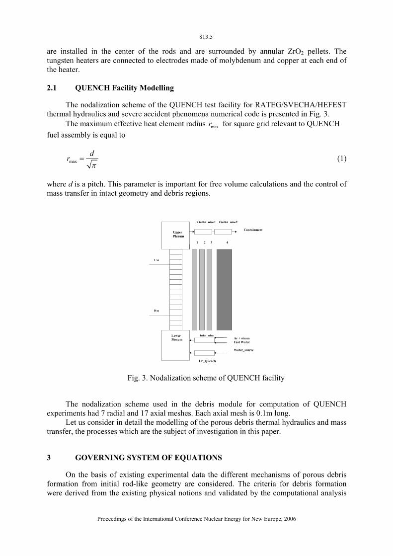
The nodalization scheme of the QUENCH test facility for RATEG/SVECHA/HEFEST thermal hydraulics and severe accident phenomena numerical code is presented in Fig. 3.
The maximum effective heat element radius for square grid relevant to QUENCH maxrfuel assembly is equal to
maxdrπ
= (1)
where d is a pitch. This parameter is important for free volume calculations and the control of mass transfer in intact geometry and debris regions.
Ar + steam Fast Water Water_source
Outlet pipe1 Outlet pipe2
LP_Quench
Containment
Lower Plenum
Upper Plenum
0 м
1 м
Inlet pipe
1 2 3 4
Fig. 3. Nodalization scheme of QUENCH facility
The nodalization scheme used in the debris module for computation of QUENCH experiments had 7 radial and 17 axial meshes. Each axial mesh is 0.1m long.
Let us consider in detail the modelling of the porous debris thermal hydraulics and mass transfer, the processes which are the subject of investigation in this paper.
3 GOVERNING SYSTEM OF EQUATIONS
On the basis of existing experimental data the different mechanisms of porous debris formation from initial rod-like geometry are considered. The criteria for debris formation were derived from the existing physical notions and validated by the computational analysis
Proceedings of the International Conference Nuclear Energy for New Europe, 2006

813.6
of severe accident experiments like QUENCH-03, PHEBUS B9+ (PWR specific) and CORA-W2 which reproduced VVER-type geometry and materials.
3.1 Main Assumptions of Analysis
The main assumptions under which the analysis is done are as following: • We deal with non-Darcian porous medium in the presence of internal heat generation; • The viscous dissipation is neglected; • The fluid is assumed to be viscous and heat-generating; • The solid is assumed to have a different temperature and is also heat-generating; • We use conservation equations for mass, momentum and energy for debris dynamics; • Two-dimensional problem is considered with axial symmetry.
3.2 Basic Equations
Continuity, momentum and energy equations for each phase are used to describe the porous debris dynamics. The approach is based on the phenomenology from the works [15-20] and presented in [21].
For example, a generalized momentum equation for a porous medium is written in the following form:
( ) 1/ 2ff ff f f f E
f f f f f f
u u Cu p g u us t s s s K K
ρ ρ μ μρ ρ
ε ε ε ε
⎛ ⎞∂⎜ ⎟+ ⋅∇ = −∇ + + Δ − −⎜ ⎟∂ ⎝ ⎠
fu u
(2)
where fu is the velocity vector, fρ the fluid density, fμ the dynamic viscosity, ε the porosity, s the saturation, p the pressure, the gravity, K the permeability and the Ergun constant [15].
g EC
4 NUMERICAL REALIZATION
The system of equations mentioned above was represented in integral form and in two-dimensional geometry for the application of a finite volume (FV) approach. Then, this system was solved using time discretization to find the general independent porous debris parameters ( sε , ε , ,f axu , ,f rau , fH , sH and p ) for the current time step based on parameters values at the previous time step. Gradient and divergence terms are approximated by ordinary methods typical of FV technics.
The momentum equation in the integral form has the property that the momentum in any control volume (microscopic or macroscopic) is changed only by flow through the surface, forces acting on the surface, and volumetric body forces. This important property is inherited by the discretized equations if the FV approach is used and the surface fluxes for adjacent control volumes are identical. If this is done, then the integral over the entire domain, being the sum of the integrals over the microscopic control volumes, reduces to a sum over the surface of the domain. Overall mass conservation and energy conservation follow in the same way from the continuity and the energy equations, respectively.
The important part of the module (Fig. 4) is the interface sub-module for the heat- and mass transfer between debris and non-debris (initial geometry) meshes. The linkage between
Proceedings of the International Conference Nuclear Energy for New Europe, 2006

813.7
different types of meshes (intact, debris, melt pool) should be done with great accuracy ensuring the total heat- and mass balance in a system.
THERMAL PROBLEM OF UNIFIED CODE
DEBRIS THERMAL HYDRAULIC MODULE
Debris solid and fluid oxidation
Calculation of thermo-physical
properties of debris solid/liquid phases
System solution (ε,s, u , fH , sH ,p) for new timestep
Calculation of debris materials relocation inside
debris and between debris and non-debris meshes
Geometry (topology) of debris from
formation criteria or input data
Matrix coefficients for conservation
equations
Fig. 4. Block-scheme showing relations between different sub-modules of debris behavior module
5 RESULTS OF QUENCH EXPERIMENTS MODELING
5.1 QUENCH-02/QUENCH-03/QUENCH-09 Test Scenarios
The QUENCH experiments consist of several phases: a first heat-up phase, a thermal equilibrium phase, a second heat-up phase, a pre-oxidation phase (optional), a transient phase, and a quenching phase.
In QUENCH-02 and QUENCH-03 tests, the thermal, mechanical and oxidation behaviour were investigated during the reflood phase for non-pre-oxidized bundle.
The three out-of-pile bundle tests QUENCH-07 to –09 [23], performed at Forschungszentrum Karlsruhe, were dedicated to investigate B4C control rod behavior and its influence on the fuel rods during a wide range of severe accident conditions under low system pressure in a Western type light water reactor.
Let us consider in more detail the QUENCH-03 and QUENCH-09 tests, for which the wide range of data is well presented in electronic format from the acquisition system, and which, along with QUENCH-02 test, revealed clearly the porous debris behaviour (maximum temperatures achieved are about 2500K). Due to a failure in the data acquisition during the QUENCH-02 experiment only a limited number of data were obtained in this test.
The electric power for QUENCH tests is presented in Fig. 5, and the following scenario is valid (see Table 1) for QUENCH-02, QUENCH-03 and QUENCH-09. There was no pre-oxidation phase in these tests.
Proceedings of the International Conference Nuclear Energy for New Europe, 2006

813.8
During the preliminary heating and heat-up transient phases, superheated steam together with the argon as carrier gas enters the test bundle at the bottom end and leaves the test section at the top together with the hydrogen that is produced in the zirconium-steam reaction.
0 1000 2000 3000 4000 5000Time, s
0
10000
20000
30000
40000
50000
Pow
er, W
QUENCH-02
QUENCH-03
QUENCH-09
Fig. 5. QUENCH-02/03/09: total electric power history
Table 1: Major Sequence of Events for QUENCH-02, -03, -09
Phase Rod simulator
temperature
Temperature increase Time
Preliminary heating in
argon-steam atmosphere
≈900K ≈0K/s <1000s (QUENCH-03),
<150s (QUENCH-02),
<150s (QUENCH-09)
Heat-up
(Ar-H2O)
900-2500K 0.4÷1.6K/s (Q-02),
0.4÷1.0K/s (Q-03),
0.4÷2.0K/s (Q-03)
1000÷2600s (Q-03),
150÷2150s (Q-02)
1000÷3000s (Q-09)
90g/s quench water
≈2500K ≈0K/s 2600s (QUENCH-03),
2150s (QUENCH-02)
40g/s quench ≈2500K −(3÷7)K/s 2630s (QUENCH-03),
2175s (QUENCH-02)
50 g/s steam ≈2500K -(3÷10)K/s 3300s (QUENCH-09)
The quench phase was initiated by turning off the argon and steam flow, filling the lower plenum (Fig. 1) with quench water at a high rate (90 g/s), and injecting argon at the bundle head. About 25÷30s later the test section was reflooded from the bottom at 40÷50 g/s H2O achieving an injection velocity of 1.6 cm/s (QUENCH-02) and 1.3 cm/s (QUENCH-03). In QUENCH-09 the quench was due turning on the high mass flux (50 g/s) of saturated
Proceedings of the International Conference Nuclear Energy for New Europe, 2006

813.9
steam. As it can be seen from the Fig. 5, during the flooding phase the electrical power was reduced to approximately 4 kW to simulate the decay heat level.
The total amount of hydrogen released during the QUENCH-02, QUENCH-03 and QUENCH-09 experiments was 190g, 123g and 460g, respectively.
The post-test appearance of both test bundles reveals severe oxidation and embrittlement (fragmentation) of the rod claddings and shroud in the upper part as well as melt formation and relocation. 5.2 QUENCH Calculation Results
In Fig. 6 the axial bundle temperature profile for QUENCH-03 is presented for time t=2250 s (before the reflood). Fig. 7 and 8 show the temporal dependence of temperature for different axial locations: 850 mm (near the upper part of heated zone) and 650 mm. QUENCH-09 temperature behavior for the level 750 mm is shown in Fig. 9.
The thermal problem is mainly influenced by heat fluxes in a system. The thermal conductivity of the isolation is one of the most pronounced factors. The thermal conductivity data for ZYFB isolation (www.zircarzirconia.com) were used in the modelling.
During the reflood phase strong secondary temperature excursions were observed in the experiment, which is reproduced in computation. This excursion is due to zirconium-steam exothermic reaction.
-400 0 400 800 1200 1600Time, s
600
800
1000
1200
1400
1600
Tem
pera
ture
, K
1
2
Fig. 6. QUENCH-03: axial temperature profile for t=2250 s 1 –experiment, 2 – calculation
Calculated hydrogen integral production for QUENCH-03 is presented in Fig. 10. There
were some difficulties in experimental determination of this parameter. Experimental value for H2 production is estimated as 123 g (18g before the reflood, 105 g after), so this value is in a reasonable consistency with computational results.
Proceedings of the International Conference Nuclear Energy for New Europe, 2006

813.10
0 1000 2000 3000 4000Time, s
0
500
1000
1500
2000
2500
3000
Cla
ddin
g te
mpe
ratu
re, K
1
2
Fig. 7. QUENCH-03: temperature elevation 850 mm: 1 –experiment (TFS3/12), 2 - calculation
Note, that according to calculation results, the oxidation in debris regions contributes a
considerable part to integral H2 production (about 26%), so this circumstance constitutes justification of implemented debris model, of course, only in some extent because the hydrogen production depends on many factors. Calculation results also showed that the major hydrogen release is connected with the reflood phase.
0 1000 2000 3000 4
0
400
800
1200
1600
1
2
re, K
ratu
Cla
ddin
g te
mpe
000 Time, s
Fig. 8. QUENCH-03: temperature elevation 650 mm:
1 –experiment (TFS3/10), 2 - calculation
Proceedings of the International Conference Nuclear Energy for New Europe, 2006

813.11
0 1000 2000 3000Time, s
400
800
1200
1600
2000
2400
2800
Tem
pera
ture
, K
1
2
Fig. 9. QUENCH-09: temperature elevation 750 mm: 1 –experiment (TFS4/11), 2 - calculation
As stated in [22], oxidation in molten pool regions has some peculiarities in comparison
to oxidation in solid. The oxidation of metallic melts is not described by application of usual kinetic correlations. Melt oxidation together with melt relocation, dispersion and fragmentation is obviously one of the most important quench phenomena.
0 1000 2000 3000 4000Time, s
0
0.04
0.08
0.12
Hyd
roge
n pr
oduc
tion,
kg
1
2
Fig. 10. QUENCH-03 calculated hydrogen production: 1 – total H2 release, 2 – H2 release in debris
Fig. 11 shows the net heat balances in a system. The major part of heat to surrounding
shroud is due to radiative heat transfer. The heat transferred by steam-argon mixture is the
Proceedings of the International Conference Nuclear Energy for New Europe, 2006

813.12
least part of integral heat balance, which is a characteristic feature of QUENCH-02, QUENCH-03 and QUENCH-09 experiments.
0 1000 2000 3000 4000Time, s
0
20000
40000
Pow
er, W
1
23
4
Fig. 11. QUENCH-03 calculation heat balances: 1 – total electric power, 2 – heat to shroud, 3 – heat transferred by gas, 4 – chemical power
The debris was formed in calculations at the axial elevations 750 through 850 mm in
accordance with experimental results. The fluid part of debris partially flowed down to lower elevation meshes where it was freezed. This qualitative picture is also resembled in post-test observations. 5.3 Mass Relocation in QUENCH Tests
The characteristic value of melt velocity in the experiment is a few mm per second, which is characteristic corium velocity for all QUENCH tests with severe damage (QUENCH-02, QUENCH-03, QUENCH-09 [1,22]). This value is in a good agreement with calculations. The Fig. 12 shows the fluid part of debris velocity module for the second radial group and the elevation of 750 mm for QUENCH-03.
The estimation of melt velocity can be done from the momentum equation (2):
ff
f f
K g Kguρμ ν
≈ = (3)
Let us take the characteristic size for debris particle 3mm. Then, the Kozeny constant K
under the conditions of QUENCH tests is about 92.75 10K −≈ ⋅ , so at characteristic kinematic viscosity of melt (value characteristic for metal melts with Zr) we could
get the following estimation
6 21.0 10 /f m sν −≈ ⋅22.75 10 /fu −≈ ⋅ m s . Taking into account the relative
Proceedings of the International Conference Nuclear Energy for New Europe, 2006

813.13
permeability Krf [16] in the presence of fluid and solid phases of debris, we get finally 1 5 /fu mm≈ ÷ s .
Fig. 13 shows the temperature dynamics on different levels during QUENCH-09 test. The spikes correspond to the arrival of fluid part of debris. From the analysis of these curves it is possible to support the above-stated estimation for characteristic fluid velocity in the range of several mm per second. The calculated velocity data are in a good agreement with this estimation (Fig. 14).
2560 2580 2600 2620 2640Time, s
0
0.004
0.008
0.012
0.016
0.02
Mel
t vel
ocity
, m/s
Fig. 12. QUENCH-03 calculated fluid velocity in debris for radial group N=2 and elevation 750 mm
2400 2600 2800 3000 3200 3400Time, s
400
800
1200
1600
2000
2400
2800
Tem
pera
ture
, K
1 - 1050 mm (TFS 3/14)2 - 850 mm (TIT D/12)
12
3
3 - 750 mm (TSH 11/0)
4
4 - 650 mm (TFS 3/10)
Fig. 13. QUENCH-09 temperature evolution showing mass relocation in debris bed
Proceedings of the International Conference Nuclear Energy for New Europe, 2006

813.14
2500 2600 2700 2800 2900 3000Time, s
0
0.002
0.004
0.006
0.008
0.01
Vel
ocity
, m/s
Fig. 14. QUENCH-09 calculated fluid velocity in debris for radial group N=2 and elevation 850 mm
Fig. 15 and 16 demonstrate some interesting debris parameters for second radial zone
and elevation of 850 mm: saturation (part of debris pore volume occupied by fluid) and porosity of debris. These figures confirm the complicated dynamics of main porous medium parameters in the course of the experiment.
2560 2580 2600 2620Time, s
0
0.2
0.4
0.6
0.8
1
Satu
ratio
n
Fig. 15. QUENCH-03 calculated saturation in debris for radial group N=2 and elevation 850 mm
In QUENCH-02 experiment modeling, the similar debris behavior was calculated as in
QUENCH-03. Due to different power history in this test, the hydrogen release is more considerable in this case: 40g before the reflood and 133g during the reflood which is in a good consistency with the experimental data.
Proceedings of the International Conference Nuclear Energy for New Europe, 2006

813.15
2560 2600 2640 2680Time, s
0
0.1
0.2
0.3
0.4
0.5
Poro
sity
Fig. 16. QUENCH-03 calculated porosity in debris for radial group N=2 and elevation 850 mm
Let us summarize the main results of the investigation. The basic thermal parameters of
experiment QUENCH-03 are adequately reproduced by the code. Integral hydrogen production is in a good agreement with the experimental value. Mass transfer in debris is also in a reasonable accordance with observed values, which looks optimistic for justification of implemented debris model.
6 CONCLUSIONS
A module for numerical modelling of core behavior with the formation of porous debris regions during severe accident’s late phase is developed. The module is implemented into the Russian best estimate severe accident code, RATEG/SVECHA/HEFEST. This numerical code is able to consider thermal hydraulics, degradation of core and other structures, hydrogen generation, and other phenomena important for realistic description of nuclear reactor severe accidents.
The application of known classical principles and introducing of some special methods allowed to describe the heat and mass transfer self-consistently in the following cases:
• Intact geometry; • Partially or totally degraded core with debris formation; • Energy exchange in the cases of considerable zones of degradation including the
molten pool regions. The modelling of QUENCH experiments showed the importance of detailed taking into
account of processes in porous debris regions for adequate description of heat and mass transfer as well as hydrogen release.
The QUENCH-02, QUENCH-03 and QUENCH-09 computational results are in a good agreement with experimental data concerning different aspects of thermal behavior: thermal
Proceedings of the International Conference Nuclear Energy for New Europe, 2006

813.16
hydraulics of porous debris, radiative heat transfer in a porous medium, the generalized melting and refreezing behavior of materials.
ACKNOWLEDGMENTS
The authors would like to thank Dr. Stuckert from FZK, Germany, for providing with the data of QUENCH tests. The work has been performed in the frame of projects on severe accident numerical code development.
REFERENCES
[1] P. Hofmann, C. Homann, W. Leiling, A. Miassoedov, D. Piel, G. Schanz, L. Schmidt, L. Sepold, M. Steinbrueck, Experimental and Calculational Results of the Experiments QUENCH-02 and QUENCH-03, FZKA 6295, Forschungszentrum Karlsruhe, July 2000.
[2] J. M. Broughton, P. Kuan and D. A. Petti, A Scenario of the Three Mile Island Unit 2 Accident, Nuclear Technology, vol. 87, 1989, p. 34.
[3] P. Hofmann, S. Hagen, V. Noack, G. Schanz, L. Sepold, Chemical-Physical Behavior of Light Water Reactor Core Components Tested under Severe Reactor Accident Conditions in the CORA Facility, Nuclear Technology, vol. 118, 1997, p. 200.
[4] B. Adroguer, A. Commande, C. Rongier, V. Mulet, International Standard Problem N 28: PHEBUS- SFD B9 + Experiment on the Degradation of a PWR CORE type, Comparison report, vol. 1, CEA/IPSN/DRS, Cadarache, France, December 1992.
[5] D. A. Petti, Z. R. Martinson, R. R. Hobbins, C. M. Allison, E. R. Carlson, D. L. Hagrman, T. C. Cheng, J. K. Hartwell, K. Vinjamuri, L. J. Siefken, Power Burst Facility (PBF) Severe Fuel Damage Test 1-4, Test Results Report, NUREG/CR-5163, EGG-2542, Idaho National Engineering Laboratory,1989.
[6] R. Nazar and I. Pop, Mixed Convection Boundary Layer Flow over a Vertical Surface in a Porous Medium with Variable Surface Heat Flux, Proc. of International Mechanical Engineering Conference IMEC2004, Kuwait, IMEC04-1007, December 5-8, 2004.
[7] F. Abdulgafoor and A. J. Chamkha, Double-Diffusive Convection in a Non-Darcian Porous Medium Enclosure in the Presence of Heat Generation or Absorption, Proc. of International Mechanical Engineering Conference IMEC2004, Kuwait, IMEC04-1008, December 5-8, 2004.
[8] H. Kazemi, Sh. Shayegh, S. Sh. Ayatollahi, A. Lashanizadegan, Experimental and Theoretical Investigation of the Temperature Profile in a Porous Fin, Proc. of International Mechanical Engineering Conference IMEC2004, Kuwait, IMEC04-1035, December 5-8, 2004.
[9] I. Pop and D. B. Ingham, Convective Heat Transfer: Mathematical and Computational Modelling of Viscous Fluids and Porous Media, Pergamon, Oxford, 2001.
[10] L. J. Siefken, E. W. Coryell, E. A. Harvego, J. K. Hohorst, SCDAP/RELAP5/MOD3.3 Code Manual. Vol.2: Modeling of Reactor Core and Vessel Behavior during Severe
Proceedings of the International Conference Nuclear Energy for New Europe, 2006

813.17
Accidents, NUREG/CR-6150, INEL-96/0422, Idaho National Engineering and Environmental Laboratory, Idaho Falls, September 2000.
[11] R. N. Summers, R. K. Cole, Jr., R. C. Smith et al., MELCOR Computer Code Manuals. Version 1.8.3. Vol. 1,2, NUREG/CR-6119, SAND93-2185, September 1994.
[12] F. Fichot, The ICARE/CATHARE Code: Status of Development and Applications to Severe Accident Analysis, AIEA Technical Committee Meeting on Modelling in-vessel phenomena under severe accident conditions, Vienna (Austria), 2000.
[13] M. Zabiego, F. Fichot, P. Rubiolo, Radiative Heat Transfer Modeling in the ICARE/CATHARE Software – Application to a PWR Severe Accident Sequence, Proc. of the 11th International Meeting on Nuclear Thermal-Hydraulics (NURETH-11), Avignon, France, October 2-6, 2005.
[14] A. Kisselev, G. Kobelev, V. Strizhov, A. Vasiliev, Radiative Heat Exchange Model for Late Phase of Severe Accident at VVER-Type Reactor, Proc. of the 18th Int. Conference on Structural Mechanics in Reactor Technology (SMIRT-18), Beijing, China, August 7-12, 2005.
[15] S. Ergun, Fluid Flow through Packed Columns, Chem. Eng. Prog., vol. 48, 1952, pp. 89-94.
[16] M. Kaviany, Principles of Heat Transfer in Porous Media, 2nd Edition, Mechanical Engineering Series, Springer-Verlag, 1994, 708 pp.
[17] M. S. Phanikumar and R. L. Mahajan, Non-Darcy Natural Convection in High Porosity Metal Foam, Int. J. Heat & Mass Transfer, vol. 45, 2002, pp. 3781-3793.
[18] S. Imura and E. Takegoshi, Effect of Gas Pressure on the Effective Thermal Conductivity of Packed Beds, Heat Transfer Japanese Research, vol. 3, 1974, p. 4.
[19] S. Yagi, D. Kunii, Studies on Effective Thermal Conductivities in Packed Beds, A.I.Ch.E. Journal, 1957, pp. 373-381.
[20] R. D. Gasser, R. O. Gauntt and S. Bourcier, Late Phase Melt Progression Experiment − MP-1, NUREG/CR-5874, SAND92-0804, Sandia National Laboratories, Albuquerque, NM, 1993.
[21] A. Kisselev, G. Kobelev, V. Strizhov, A. Vasiliev, Numerical Module for Debris Behavior under Severe Accident Conditions, Proc. of the Int. Conference “Nuclear Energy for New Europe 2005” (NENE-2005), Bled, Slovenia, September 5-8, 2005, NENE-2005-158.
[22] M. Veshchunov, Interpretation of Melt Oxidation in QUENCH-09 Test, Proc. of 11th International QUENCH Workshop, Karlsruhe, Germany, October 25-27, 2005.
[23] C. Homann, W. Hering, G. Schanz, Analysis and Comparison of Experimental Data of Bundle Tests QUENCH-07 to QUENCH-09 about B4C Control Rod Brehavior, FZKA 7101, Forschungszentrum Karlsruhe, July 2006.
Proceedings of the International Conference Nuclear Energy for New Europe, 2006