portable data collection system (pdcs) operating manual
TRANSCRIPT

Sydney OfficeBrookvale(02) 9939 [email protected]
Perth OfficeNowergup(08) 9407 5363
Melbourne OfficeNiddrie(03) 9938 [email protected]
Websitewww.pcte.com.au
Portable Data Collection System
(PDCS)Operating Manual
PDCS Operating Instruction Manual – (C)t/¢9 2010
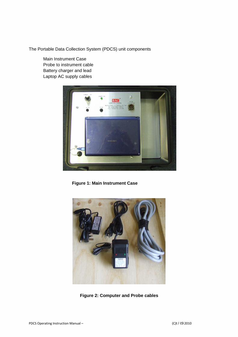
The Portable Data Collection System (PDCS) unit components
Main Instrument Case
Probe to instrument cable
Battery charger and lead
Laptop AC supply cables
Figure 1: Main Instrument Case
Figure 2: Computer and Probe cables

PDCS Operating Instruction Manual – (C)t/¢9 2010
Description
The corrosion monitoring portable data collection system when used with the ‘Type CL’corrosion monitoring probe is an advanced embeddable corrosion rate monitoring system.Using the probes unique design – four independent LPR electrodes at varying levels ofconcrete cover and automated testing software allow the determination of a variety ofparameters relating to the condition of the structure. The monitoring system collects thedata so it can be analysed to provide an indication of the rate of ingress of corrosivesubstances into the concrete and hence estimates can be made regarding the potential lifeof the structure.
Functions
Corrosion Rate measurements at each of the four electrodes plus main steelreinforcement
Corrosion Potential measurements at each of the four electrodes plus main steelreinforcement
Electrical Resistance (between three pairs of electrodes) Temperature of probe Estimation of rate of ingress of corrosive substances
Specification
Size: 53cm W x 43cm D x 18cm HWeight: 9kg
Operating Instructions
Step 1: Prior to using the meter, ensure that the instrument battery is fully charged. Connectthe charger to the instrument using the DC IN socket. Plug the charger into a 240V ACsupply and switch on, ensure the selector switch is set to “CHARGE”.
The unit cannot run from an external power source. When using the meter remove theDC IN connection to the battery charger.
Step 2: Ensure that the Notebook is fully charged and switch on and if necessary connect tothe internet either by wireless or network connection and ensure that Windows is up to date
Step 3: once you have arrived at a probe location, open the lid and switch on the computer.
Step 4: Attach the Probe to the main instrument using the cable provided. The connectersmust be aligned correctly, and the locking swivel turned to secure the cable.
Step 5: Switch the instrument selector switch to ON. The POWER ON LED will illuminate.

PDCS Operating Instruction Manual – (C)t/¢9 2010
Step 6: Run the CMSCL (Corrosion Monitoring System – CL) program by double clicking theicon on the desktop or by finding the program on the start menu.
Figure 3: The CMSCL program running
Step 7: The unit is delivered with the USB configured to “Com Port 4”. The USB connector
should always be inserted in the same slot as delivered.
Figure 4: The CMSCL program running

PDCS Operating Instruction Manual – (C)t/¢9 2010
Step 8: The software can check whether all the connections have been made correctly by
using the “Test” button. This will open the monitor screen to the left of the CMS interface
screen. If there are any errors, then the monitor will stay blank. If all the connections are
correct and the battery is sufficiently charged, then the instrument will perform a quick self
diagnostic and display the remaining battery charge in the CMS interface screen.
Figure 5: The self diagnostic screen after the "Test" button has been pushed
Step 9: Before the program can be run, a save file must be created/selected. To do this, usethe “Set File” button which opens the windows saving screen. The default file is “CMSdata”
Figure 6: The save screen showing the default save

PDCS Operating Instruction Manual – (C)t/¢9 2010
Step 10: Once the save file has been created, the “Run” button becomes available (as long
as the save file is not being viewed in a spreadsheet (see step 11) and once clicked, the
instrument will begin its operation. The progress can be viewed using the “Show Monitor”
button and can be interrupted at any point by using the “Stop” button. Once the operation
has been completed, the “Stop” button will become non selectable again.
Figure 7: The monitor, showing the progress of the operation
Figure 8: The monitor once the operation has finished, note the "Stop" button hasbecome non selectable

PDCS Operating Instruction Manual – (C)t/¢9 2010
Step 11: When the operation has been completed, all the cables can be removed and stored
in preparation for their next use. The data from the probes can be reviewed by opening the
saved file selected/created earlier in the spreadsheet.
Figure 9: Spreadsheet showing the data recorded by the PDCS unit

PDCS Operating Instruction Manual – (C)t/¢9 2010
Interpretation
Corrosion rates are best monitored over long periods analysing ‘trending’ to determine ifconditions change and if corrosion rates increase with time.
Graphical presentation of the measured corrosion rate data, plotted against time,demonstrates trends and enables assessment of the corrosion condition of the structure.Plots showing corrosion rates and corrosion potentials at each carbon steel element depthalong with those of the main rebar are useful. Results should however be reviewed by acorrosion engineer with particular experience in interpreting corrosion rate data in reinforcedconcrete.
A broad set of criteria for corrosion has been developed from field and laboratoryinvestigations and is reproduced in Figures 4.12 and 4.14 in the book “Corrosion of Steel inConcrete” authored by John P Broomfield (1).
Based on the actual surface areas of the four Type CL probe carbon steel elements theinformation given in tables by Broomfield can be adapted as a basis for interpretation for theelements. These readings provide a measure of the corrosion rates at the time of testing.
Table 1 – Readings taken by PDCS of Type CL probe elements (µm/yr)
< 0.3 Passive conditions0.3 – 3.0 Low to Moderate Corrosion3.0 – 30.0 Moderate to High Corrosion
> 30.0 High Corrosion
For the main rebar a calibration divisor should be derived by equating the measuredcorrosion rate of the fourth carbon steel element to that of the main rebar. The main rebarshould be at the same depth in the concrete and therefore in similar conditions.
For example, if the PDCS reading of corrosion rate for the fourth element is 3.5 µm/yr andthe main rebar is 15.5 µm/yr, then use a divisor of 3.5/15.5 = 0.223. Multiply all further mainrebar readings by 0.223. The actual divisor should be derived from the first few readings sayat 3 monthly intervals.
This is because the actual surface area of the main rebar measured during themeasurement process is unknown and the measurement meter uses a standard 100cm²surface area to derive corrosion rates. The fourth carbon steel element (surface area of30cm²) is used as a means of calibrating the surface area of the main rebar perturbatedduring the measurement process.
Care must be used in interpretation. Passivation of steel in new concrete can be quite slow.
Initial measured corrosion rates may decrease over the first few years as available oxygen is
used in the initial corrosion process, then stabilise, thereafter increasing when the onset of
contamination (chloride or carbonation) induced corrosion takes place.
It is likely that the corrosion rates for the outermost element (element No1 closest to the
concrete surface) will be higher than that for element No 2 etc. This provides an indication of
ingressing depassivating ions (usually chlorides). The rebar should be in similar condition to
the fourth carbon steel element.
(1)Broomfield, J P, “Corrosion of Steel in Concrete 2
ndEdition”, Taylor & Francis – ISBN 978-0-415-33404-4,
2007

PDCS Operating Instruction Manual – (C)t/¢9 2010
Fault Finding
Fault Possible cause Solution
POWER ON LED does not
light
Switch is in the CHARGE
positionTurn unit to ON position
Battery is flat Charge battery with the
supplied chargerFuse is blown Replace fuse
No communication with
probe
Switch is in the CHARGE
positionTurn unit to ON position
Check probe cable is
connected
Check connections are
correct and ensure the
swivels are in the locked
positionCommunication channel
incorrect
Select the correct
communication port in the
software on the computer
Battery Level LowCharge battery with the
supplied charger
Damaged cable Replace cable
Damaged Connectors Replace cable
Computer fails to switch on Battery is flatCharge battery with the
supplied charger
Battery fails to charge
Switch position not set to
CHARGE
Turn unit to CHARGE
position
Fuse is blown Replace fuse
Contact Detail
Technical support & spares are available from: