portable data logger with 30 standard channels expandible...
TRANSCRIPT

MEMORY HiLOGGER
Data Loggers
LR8400-20, LR8401-20, LR8402-20
Portable Data Logger with 30 Standard Channels Expandible to 60 Channels
Only the size of an A4 sheet of paper, the HIOKI LR8400-20 Series is the real-ization of our goal to build a logger that provides the existing functionality of a multi-channel data logger in a portable format. The new model comes with 30 channel capability as standard, to which another 30 channels can be added. All input channels for measuring temperature (with thermocouples), or voltage are isolated for safety, culminating in a powerful multi-measurement system that also offers pulse and logic inputs. Long-term logging is coupled with the capability to protect data against unexpected power outages and other problems for stable re-cordings over an entire year (see note).Note: Continuous recordings lasting longer than 1 year are also possible.

2
In fuel cell, electric automobile and other development
n High withstand voltage
The HiLOGGER measures not only fuel cells, but also batteries for UPS (uninterruptible power supplies) devices used in buildings as well as batteries consisting of cells and packaging connected in stacks that require multi-point measurements. In such measurements, high voltage for the whole stack is applied between channel-to-channel and channel-to-ground. Only a measuring instrument with isolated inputs and high-capacity withstand voltage characteristics can endure this.
n High-speed sampling
In the development of automobiles such as electric vehicles (EV) and plug-in hybrid vehicles (PHV) that use motors for propulsion, abrupt changes in load need to be measured.This makes the multi-channel, high-speed 10 ms sampling capability of the LR8400-20 Series an indispensable feature.
n Multi-channel measurements
In the development of fuel cells, multiple power-generating cells are connected to form a stack. Independent measurements of each cell require multi-channel measurements of DC voltage, DC current, temperature and other parameters. The LR8400-20 Series comes with 30 channels as standard, which can be expanded to 60 channels.
n Environmental measurements to prevent global warming
n Development of fuel cell materials, energy field
n Development of automobiles, testing of automobile parts
n Maintenance and inspection of equipment
n Monitoring plantsn Testing of electrical productsn Impedance testing of electronic
parts
n Maximum rated voltage to earth: 300 V AC/DC
n Maximum voltage that can be input between terminals: ±100 V DC
n Maximum rated voltage between each channels of VOLTAGE/TEMP UNIT: 250 V DC
n Maximum rated voltage between each channels of UNIVERSAL UNIT: 300 V DC
Provides assistance
with
Note: Isolation between channels is possible through the use of semi-conductor relays. Voltage exceeding the product specifications, such as that originating from lightning surges or other sources, should never be applied between each channel; otherwise the relays will short and the recorder will be damaged.
3
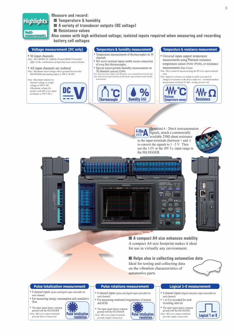
Measure and record: nTemperature & humidity nA variety of transducer outputs (DC voltage) nResistance valuesAlso comes with high withstand voltage; isolated inputs required when measuring and recording
battery cell voltages
Voltage measurement (DC only) Temperature & humidity measurement•Temperature measurements of thermocouples on 30
channels•M3 screw terminal inputs enable secure connection
of even thin thermocouples•Special sensor permits humidity measurements on
30 channels (optional Z2000)Note: The sensor power supply is the M3 mm dia. screw terminal block on the left side.Note: Both universal input terminals and M3 mm dia. input terminals enable humidity
measurements.
•30 input channelsNote: The LR8400-20, LR8401-20 and LR8402-20 models
differ in the combination of input functions and terminals.
•All input channels are isolatedNote: Maximum rated voltage above ground between the
HiLOGGER and analog inputs is 300 V AC/DC.
Note: Maximum channel-to-channel voltage is a high voltage of 300 V DC.
(Maximum voltage for models with M3 screw input terminals is 250 V DC.)
•8 channel inputs (pulse and digital input selectable for each channel)
•For measuring energy consumption and cumulative flow
•The input signal shares common ground with the HiLOGGER
Note: M3 screw input terminals provide direct connection
•8 channel inputs (pulse and digital input selectable for each channel)
•For measuring rotational irregularities of motors and drills
•The input signal shares common ground with the HiLOGGER
Note: M3 screw input terminals provide simple connection
•8 channel inputs (digital and pulse input selectable for each channel)
•1 or 0 is recorded for each recording interval
•The input signal shares common ground with the HiLOGGER
Note: M3 screw input terminals provide simple connection
Pulse totalization measurement Logical 1-0 measurementPulse rotations measurement
Highlights
Multi-measurements
Temperature & resistance measurement
•Universal inputs support temperature measurements using Platinum resistance temperature sensor (Pt100/ JPt100), or resistance measurements (four wires)
Note: These cannot be measured using the M3 screw input terminals units.
Note: Supports resistance recording to enable assessment of changes in resistance in the device under test. 4-terminal method, measurement resolution 0.5 mΩ -, testing current 1 mA
nA compact A4 size enhances mobilityA compact A4 size footprint makes it ideal for use in virtually any environment.
nHelps also in collecting automotive dataIdeal for testing and collecting data on the vibration characteristics of automotive parts
To record 4 - 20mA instrumentation signals, attach a commercially available 250Ω shunt resistance
to the input terminals (between + and -) to convert the signals to 1 - 5 V. Then use the 1-5V or the 10V f.s. input range in the HiLOGGER.

4
nEnhanced noise suppressionA digital oversampling filter function reduces inverter switching noise and 50/60 Hz hum noise, a concern in earlier models, during recording.
Note: The noise reduction effect improves with longer recording intervals (i.e., at slower sampling speeds).
Sampling at 100 ms intervals cannot capture abrupt load changes
n10 ms high-speed samplingThe development of hybrid and electric automobiles requires instruments that can measure abrupt load changes. Channels 1 to 15 provide 10-ms sampling and channels 16 to 30 provide 20-ms sampling. This channels allow you to track waveforms not possible with earlier models.
Note: Measurements on channels 31 to 60 provide 50-ms sampling.
Accurately capture any phenomena you want to measure
Sampling the same waveform at ten times the speed, at 10 ms intervals, accurately captures the changes.
Without electric noise reduction, you will obtain a waveform like the one above in temperature measurements of an electromagnetic cooker
A digital filter in the HiLOGGER eliminates high-frequency noise to enable accurate temperature waveforms
n5.7 inch TFT LCD display is easy to view even at an angleThe LCD has a wider visual angle and is larger (5.7 inches, 640 × 480 dots)
than the STN LCD in our previous model (8420-51s) to facilitate observation of waveforms on multiple channels.
Highlights
High-speedRecording
Highlights
Noisesuppression
Highlights
Easy-to-view LCD
5
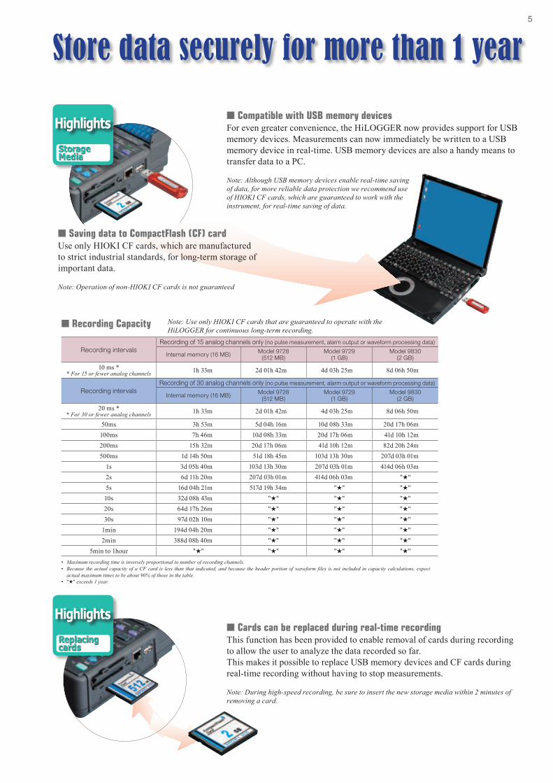
nCompatible with USB memory devicesFor even greater convenience, the HiLOGGER now provides support for USB memory devices. Measurements can now immediately be written to a USB memory device in real-time. USB memory devices are also a handy means to transfer data to a PC.
Note: Although USB memory devices enable real-time saving of data, for more reliable data protection we recommend use of HIOKI CF cards, which are guaranteed to work with the instrument, for real-time saving of data.
nCards can be replaced during real-time recordingThis function has been provided to enable removal of cards during recording to allow the user to analyze the data recorded so far. This makes it possible to replace USB memory devices and CF cards during real-time recording without having to stop measurements.
Note: During high-speed recording, be sure to insert the new storage media within 2 minutes of removing a card.
Recording intervalsRecording of 15 analog channels only (no pulse measurement, alarm output or waveform processing data)
Internal memory (16 MB) Model 9728(512 MB)
Model 9729(1 GB)
Model 9830(2 GB)
10 ms ** For 15 or fewer analog channels 1h 33m 2d 01h 42m 4d 03h 25m 8d 06h 50m
Recording intervalsRecording of 30 analog channels only (no pulse measurement, alarm output or waveform processing data)
Internal memory (16 MB) Model 9728(512 MB)
Model 9729(1 GB)
Model 9830(2 GB)
20 ms ** For 30 or fewer analog channels 1h 33m 2d 01h 42m 4d 03h 25m 8d 06h 50m
50ms 3h 53m 5d 04h 16m 10d 08h 33m 20d 17h 06m 100ms 7h 46m 10d 08h 33m 20d 17h 06m 41d 10h 12m 200ms 15h 32m 20d 17h 06m 41d 10h 12m 82d 20h 24m 500ms 1d 14h 50m 51d 18h 45m 103d 13h 30m 207d 03h 01m
1s 3d 05h 40m 103d 13h 30m 207d 03h 01m 414d 06h 03m 2s 6d 11h 20m 207d 03h 01m 414d 06h 03m "H"5s 16d 04h 21m 517d 19h 34m "H" "H"10s 32d 08h 43m "H" "H" "H"20s 64d 17h 26m "H" "H" "H"30s 97d 02h 10m "H" "H" "H"
1min 194d 04h 20m "H" "H" "H"2min 388d 08h 40m "H" "H" "H"
5min to 1hour "H" "H" "H" "H"• Maximum recording time is inversely proportional to number of recording channels.• Because the actual capacity of a CF card is less than that indicated, and because the header portion of waveform files is not included in capacity calculations, expect
actual maximum times to be about 90% of those in the table.• "H" exceeds 1 year.
Note: Use only HIOKI CF cards that are guaranteed to operate with the HiLOGGER for continuous long-term recording.
Store data securely for more than 1 year
nSaving data to CompactFlash (CF) cardUse only HIOKI CF cards, which are manufactured to strict industrial standards, for long-term storage of important data.
Note: Operation of non-HIOKI CF cards is not guaranteed
n Recording Capacity
Highlights
StorageMedia
Highlights
Replacingcards

6
nUp to two additional 15 channel input units can be added
The need for more measurement channels can be met even after purchasing the instrument. The instrument comes with 30 channels as standard, but another two 15 channel input units can be added to expand the total number of channels to 60.
Note: The units provided with the unit as standard cannot be removed.
A host of useful functions and features
nInput setting screens with waveform monitoringThe HiLOGGER adopts the setting screens that earned its sister model (8430-20) a reputation for user-friendliness. Range settings, warnings, triggers, waveform processing and other measurement input settings can be taken in at a glance.
VOLTAGE/TEMP UNIT LR8500l15chlM3 screw terminals (2 terminals per channel)
UNIVERSAL UNIT LR8501l15chlPush-button type terminals (4 terminals per channel)
Function highlightsEasyinstallation
Function highlightsEase of use
7
LAN
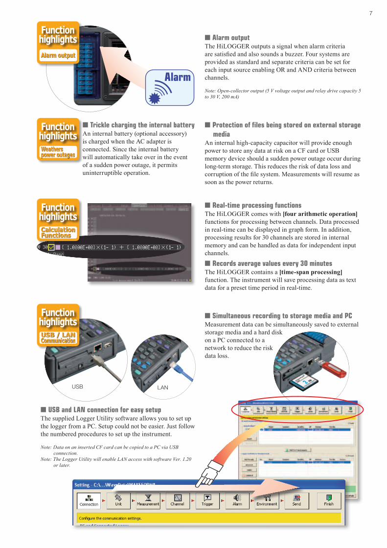
nUSB and LAN connection for easy setupThe supplied Logger Utility software allows you to set up the logger from a PC. Setup could not be easier. Just follow the numbered procedures to set up the instrument.
Note: Data on an inserted CF card can be copied to a PC via USB connection.
Note: The Logger Utility will enable LAN access with software Ver. 1.20 or later.
nSimultaneous recording to storage media and PCMeasurement data can be simultaneously saved to external storage media and a hard disk on a PC connected to a network to reduce the risk data loss.
USB
nReal-time processing functionsThe HiLOGGER comes with [four arithmetic operation] functions for processing between channels. Data processed in real-time can be displayed in graph form. In addition, processing results for 30 channels are stored in internal memory and can be handled as data for independent input channels.
nTrickle charging the internal batteryAn internal battery (optional accessory) is charged when the AC adapter is connected. Since the internal battery will automatically take over in the event of a sudden power outage, it permits uninterruptible operation.
nProtection of files being stored on external storage media
An internal high-capacity capacitor will provide enough power to store any data at risk on a CF card or USB memory device should a sudden power outage occur during long-term storage. This reduces the risk of data loss and corruption of the file system. Measurements will resume as soon as the power returns.
nAlarm outputThe HiLOGGER outputs a signal when alarm criteria are satisfied and also sounds a buzzer. Four systems are provided as standard and separate criteria can be set for each input source enabling OR and AND criteria between channels.
Note: Open-collector output (5 V voltage output and relay drive capacity 5 to 30 V, 200 mA)
nRecords average values every 30 minutesThe HiLOGGER contains a [time-span processing] function. The instrument will save processing data as text data for a preset time period in real-time.
Function highlightsAlarm output
Function highlightsWeatherspower outages
Function highlightsCalculationFunctions
Function highlightsUSB / LANCommunication

8
nAnalyze after measuringOur new “dual-knob function” greatly simplifies data analysis. Two separate waveform windows are provided, with the displayed waveforms showing different time-axis scales (time bases). This capability substantially simplifies long-term data analysis.
Segment A50 ms/div magnification
Segment B100 ms/div magnification
Entire Recording Length: 1 s/div
Segment A View Segment B View
n The supplied Logger Utility software enables processing of measurement data on a PC
n View past data during recordingn Output PC data to a printer
nControl of measurements from a PC screenConnect the PC to the HiLOGGER using USB or via LAN* (see note). Use the supplied Logger Utility software to record data on a PC in real-time. Scroll backwards through the displayed trend graph window to view past waveforms even while recording. Up to five HiLOGGERs can be connected to one PC.
Bundled user-friendly software for PC analysis
nRemote control through HTTP server function*Without the need to install additional software, you can use an ordinary web browser on your PC to set up the HiLOGGER, acquire data and monitor data on the screen.Note: Waveform data cannot be downloaded from internal memory while measuring.
nData acquisition via FTP*FTP allows the PC to acquire files stored on HiLOGGER storage devices or measurement data in internal memory.
Note: Waveform data cannot be downloaded from internal memory while measuring.
nData transfer via FTP*Data saved in real-time to storage media can be automatically transferred to an FTP server started from the PC either at regular intervals during measurements or when measurements end.
nBe informed via E-mail*Your PC or mobile device is notified of storage media full, internal memory full, stop trigger invoked, alarm occurrence and other events via E-mail.*Note: LAN communication functions support planned from software Ver. 1.20.
Function highlightsPCMeasurement

9
General specifications (product and accuracy guaranteed for one year)Internal memory 16 Mega-bytes (8M data points)Internal clock Auto calendar, Precision ±3 s/ day (at 23 °C/ 73 °F)Accuracy of timebase ±0.2s/ day on measurement (at 23 °C/ 73 °F)Backup battery For clock and setting conditions: battery life 5 years (at 23 °C/ 73 °F)Operating temp. & humidity
0 °C (32 °F) to 40 °C (104 °F), 80 % rh or less (non-condensating, when charging: 10 °C/ 50 °F to 40 °C/ 104 °F)
Storage temp. & humidity -10 °C (14 °F) to 60 °C (140 °F), 80 % rh or less, (non-condensating)
Conforming standards Safety : EN61010, EMC : EN61326, EN61000-3-2, EN61000-3-3
Anti-vibration JIS D1601: 1995 5.3 (1) Corresponds to Class 1: a passenger car, Condition: class A
External control terminal
External trigger input, Trigger output, 4 channel alarm outputs, +12 V/ 100 mA max. output, GND
Dimensions & Mass
Approx. 272 mm (10.71 in) W × 182.4 mm (7.18 in) H × 66.5 mm (2.62 in) D, 1.8 kg (63.5 oz), (LR8400 main unit, except the Battery Pack 370 g/ 13.1 oz)
Approx. 272 mm (10.71 in) W × 234.8 mm (9.24 in) H × 66.5 mm (2.62 in) D, 2.6 kg (91.7 oz), (LR8500 × 2 and LR8400 × 1, except the Battery Pack 370 g/ 13.1 oz)
Accessories Detailed operating manual ×1, Measurement guide ×1, AC ADAPTER 9418-15 ×1, USB cable ×1, CD-R (data collection software "Logger Utility") ×1
Data storage mediaCF card CF card slot ×1 (Up to 2GB), Data format: FAT, FAT32USB memory Series A receptacleCommunication function
LAN interface(ver. 1.20 or later)
IEEE 802.3 Ethernet 100BASE-TX, DHCP, DNS capable• Data acquisition, condition settings used with the Logger Utility software
(supplied as standard)• Use the communication command to set and measure• Data download via FTP server function (stored in the CF card or the USB memory)• Automatically transmit data via FTP client function• Remote control via HTTP server function• Send mail function via E-mail system
USB communication interface
USB 2.0 High-speed capable, series mini-B receptacle• Data acquisition, condition settings used with the Logger Utility software (supplied as standard)
• Configure the unit and measure using communication commands• Transfer data from the CF card to a PC via USB drive mode (data transfer not possible from USB memory sticks)
Display section
Display device5.7 inch TFT color liquid crystal display (640 × 480 pixel), horizontal 15 division, vertical 10 division, selectable between English and Japanese displays, Back light saver available
LCD Brightness Selectable from 100, 70, 40, or 25 %Power supplies
AC PowerUsing the AC ADAPTER 9418-15 (supplied as standard, 100 to 240 VAC, 50/60
Hz), Power consumption: 7 VA (with battery pack removed and maximum brightness)
DC Power
Using the BATTERY PACK Z1000 (optional accessory, AC adapter has priority when used in combination with battery pack)
Continuous operation time: 5 hours (at 23 °C, LCD brightness 25 %)Fast recharging time: 3 hours (using the AC adapter and main unit to recharge the battery, at 23 °C, reference value)
External
10 to 28 VDC (Rechargable voltage 12 to 16 VDC, Please contact your HIOKI distributor for connection cord)
Maximum rated power: 24 VA (at 16 VDC external power supply, battery charge, LCD brightness 100 %)
Trigger functions
Trigger mode, timing
Modes : Single / Repeat, Timing : Start / Stop / Start & Stop, Logical sum (OR) and product (AND) of each trigger source, Selectable for each channel
Analog signal source
Configure each individual channel for 30 channels or up to 60 channels depending on number of additional terminal modules installed.
[Level trigger] Triggers when rising or falling through preset level[Window] Triggers when entering or exiting range defined by preset upper and lower limit values
Pulse signal source
8 channels of pulse totalizer inputs[Level trigger] Triggers when rising or falling through preset level[Window] Triggers when entering or exiting range defined by preset upper and lower limit values
Digital signal source
8 channels of digital signal inputs[Logic pattern trigger] agreement (or disagreement) in the specified [1/ 0/ ×] pattern
Timer trigger Set up for year/ month/ day/ hour/ minute/ second
Trigger output Open collector (active low, with 5 V output, at least 10 ms pulse width), M3 mm screw terminal
Alarm outputNumber of channels 4 channels, non-isolated (common ground with chassis)
Alarm source 60 channels of analog input, 8 channels of pulse totalizer inputs or digital inputs, Thermocouple burn-out detection
Alarm type Level, Window, Logic pattern, Output latch/ no latch, Cancel alarm while measuring
Alarm sound Buzzer, ON/OFF possible
Alarm output Open collector (active low, with 5 V output), M3 mm screw terminal, Output refreshed at every recording interval
Output sink current 200 mA at 5 V to 30 VDC
Measurement Settings
Recording Intervals(sampling period)
10 ms*1, 20 ms*2, 50 ms*3, 100 ms to 1 hr (19 selections)Note: All input channels are scanned at high speed during every recording interval
*1 Thermocouple burn-out detection OFF, and using up to 15 channels*2 Thermocouple burn-out detection OFF, and using up to 30 channels, or Thermocouple burn-out detection ON, and using up to 15 channels
*3 Thermocouple burn-out detection OFF, and using up to 60 channels, or Thermocouple burn-out detection ON, and using up to 30 channels
Graph time axis 100 ms/ div to 1 day/ div (21 selections)Note: Setting is independent from the recording interval
Recording Time Enable continuous recording ON (records until the Stop key is pressed), or continuous recording OFF (enable a specified time span)
Repeating Recording (ON/OFF) Enable to repeat recording after the specified recording time span has elapsed
Data SavingStorage media Select a CF card or USB memory (Use only PC Cards sold by HIOKI)
Storage operation Auto: Save waveform data or time divided calculation results in real timeManual: Push the save key (operation select: item choose/ directly save)
Real-time saving
Possible: Waveforms are saved approximately one minute as binary or text data to the CF card or the USB memory (if sampling rate is slower than 1 minute, waveforms are saved at each interval)
To the PC: Waveforms are saved to the HDD in the PC via LAN or USB communication when used with the Logger Utility Software. Data can be saved in real time to the CF card or USB memory at the same time.
Divided saving
Simple divide: Save waveform data at pre-set times into separate files from the time measurement starts.
On schedule: Designate a reference time within 24 hours and save data into separate files at every set time interval starting from the reference time.
Delete & save Endless loop saving: New file overwrites the oldest file when the CF card or USB memory capacity runs short
Interruptions during saving
Storage media may be removed during real-time save after message confirmation.
Upon inserting the storage media again, data saved in internal memory during that time will be saved as a separate file in the media.
Data protectPossible: When a power failure occurs during real-time save, the file close sequence is completed before the unit is shut down. When powering with batteries and low battery power is detected, the file close sequence will automatically be executed.
Saved data types Setting condition, Waveform data (binary or text style), Calculation of numerical value, Screen data (compressed BMP)
Loading data Stored binary data can be recalled by the HiLOGGER in 16 MB quantities
Calculation functionNumerical value calculations
No. 1 to 6, maximum 6 calculations can be conducted simultaneouslySelections: average value, peak value, maximum value, time at maximum value, minimum value, time at minimum value
Data range of calculation
During measurement or after stopping: Store all data or data between A and B cursors into internal memory
Times: Calculate values at pre-determined 1 sec to 1 day intervals and display the latest value
Calculation value save
Possible: After measuring the last calculated value is automatically saved to the CF card or USB memory as a text file
Timed save: Save calculated data at pre-determined 1 sec to 1 day intervals as text data to the CF card or USB memory in real time.
Waveform calculations
*4 arithmetic calculations between each channel*Separate display of calculation graphs (only during measurement) and input waveforms
*Real-time save of calculation graph dataOther functions
Event markingSearch: Move to the event number entered and display the waveforms appearing before and after event
Number of events: Maximum 100 per measurement
A-B cursorMeasurement: time difference between A and B, electric potential difference, electric potential of A or B and time
Type: Trace the data, amplitude axis, time axisScaling Convert and display the measurement value of each channel as a scaled valueRate adjustment Scaling can be set for a channel so that its value is the same as that for UNIT1-CH1Comment input Enter a title or a comment for each channel
Other Start backup, save ten types setting conditions into main unit, auto set up, start/stop key lock, key-lock, beep sound
Pulse, Digital input
Number of channels 8 channels, (digital / pulse selectable for each channel, M3 screw terminal × 8ch, 2 terminals per channel, not isolated, common ground)
Input condition No-voltage 'a' contact (normally open contact), open collector or voltage input, Input resistance: 1.1 MΩ
Max. allowable input 0 V to 50 VDC (maximum voltage between input terminals that does not cause damage)
Max. rated voltage between channels Not isolated (common ground)
Max. rated voltage to earth Not isolated (common ground)Detect level 2 selectable levels (H: over 1.0 V, L: 0 - 0.5 V), (H: over 4.0 V, L: 0 - 1.5 V)
Pulse input period With filter OFF: 200 μs or more (both H and L periods must be at least 100 μs)With filter ON: 100 ms or more (both H and L periods must be at least 50 ms)
Slope Rising or falling edge can be set for each channel
Pulse measurement mode
Totalized pulses: Integrated (pulse count integration from start), Instantaneous (pulse count value at each sampling, and integrated value is reset each time)
Rotation count: Count input pulses during one secondFilter For contact bound resistant (ON/OFF set for each channels)Measurement parameters Ranges Finest Resolution Range of Measurements
Pulse totalization 1,000 M (pulse) f.s. 1 (pulse) 0 to 1,000 M (pulse)
Pulse rotations5,000/n (r/s) f.s. 1/n (r/s) 0 to 5,000/n (r/s)
"n" above is the number of sensor output pulses per rotation, 1 to 1,000Digital input Record logical "1" or "0" at each sampling
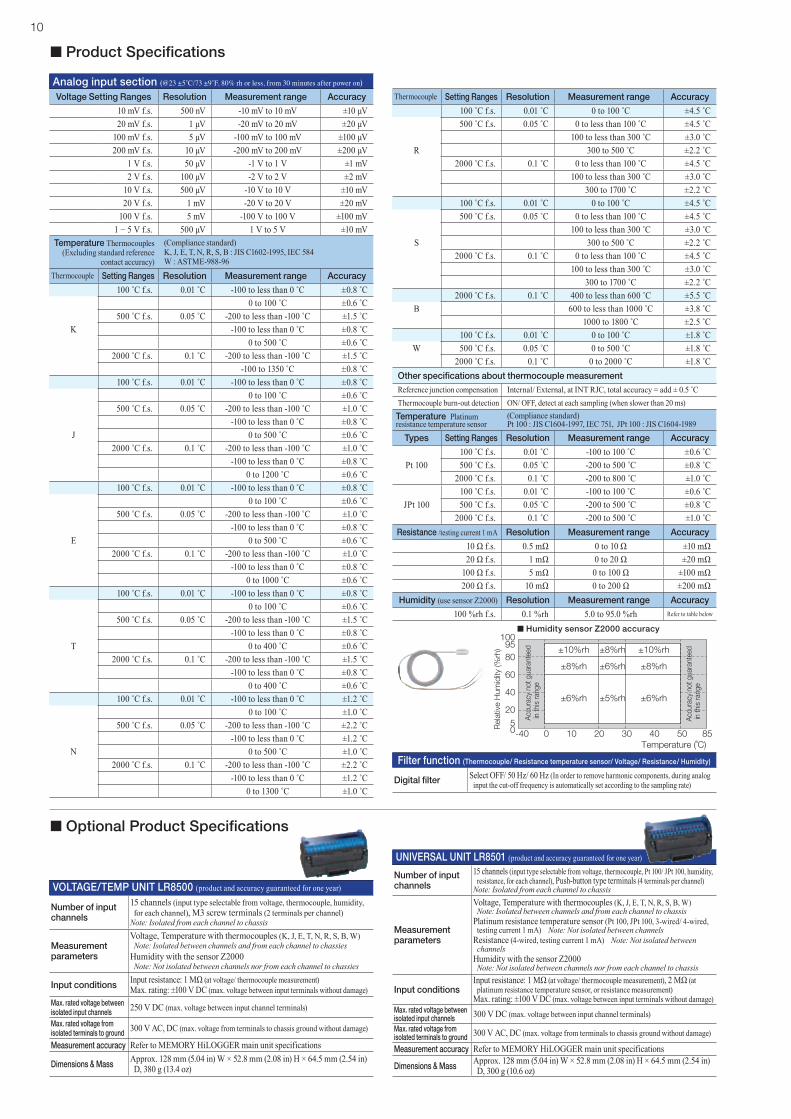
n Product Specifications
10
VOLTAGE/TEMP UNIT LR8500 (product and accuracy guaranteed for one year)
Number of input channels
15 channels (input type selectable from voltage, thermocouple, humidity, for each channel), M3 screw terminals (2 terminals per channel)
Note: Isolated from each channel to chassis
Measurement parameters
Voltage, Temperature with thermocouples (K, J, E, T, N, R, S, B, W) Note: Isolated between channels and from each channel to chassiesHumidity with the sensor Z2000 Note: Not isolated between channels nor from each channel to chassies
Input conditions Input resistance: 1 MΩ (at voltage/ thermocouple measurement)Max. rating: ±100 V DC (max. voltage between input terminals without damage)
Max. rated voltage between isolated input channels 250 V DC (max. voltage between input channel terminals)
Max. rated voltage from isolated terminals to ground 300 V AC, DC (max. voltage from terminals to chassis ground without damage)
Measurement accuracy Refer to MEMORY HiLOGGER main unit specifications
Dimensions & Mass Approx. 128 mm (5.04 in) W × 52.8 mm (2.08 in) H × 64.5 mm (2.54 in) D, 380 g (13.4 oz)
UNIVERSAL UNIT LR8501 (product and accuracy guaranteed for one year)
Number of input channels
15 channels (input type selectable from voltage, thermocouple, Pt 100/ JPt 100, humidity, resistance, for each channel), Push-button type terminals (4 terminals per channel)
Note: Isolated from each channel to chassis
Measurement parameters
Voltage, Temperature with thermocouples (K, J, E, T, N, R, S, B, W) Note: Isolated between channels and from each channel to chassisPlatinum resistance temperature sensor (Pt 100, JPt 100, 3-wired/ 4-wired, testing current 1 mA) Note: Not isolated between channels
Resistance (4-wired, testing current 1 mA) Note: Not isolated between channels
Humidity with the sensor Z2000 Note: Not isolated between channels nor from each channel to chassis
Input conditionsInput resistance: 1 MΩ (at voltage/ thermocouple measurement), 2 MΩ (at
platinum resistance temperature sensor, or resistance measurement)Max. rating: ±100 V DC (max. voltage between input terminals without damage)
Max. rated voltage between isolated input channels 300 V DC (max. voltage between input channel terminals)
Max. rated voltage from isolated terminals to ground 300 V AC, DC (max. voltage from terminals to chassis ground without damage)
Measurement accuracy Refer to MEMORY HiLOGGER main unit specifications
Dimensions & Mass Approx. 128 mm (5.04 in) W × 52.8 mm (2.08 in) H × 64.5 mm (2.54 in) D, 300 g (10.6 oz)
n Optional Product Specifications
Analog input section (@23 ±5˚C/73 ±9˚F, 80% rh or less, from 30 minutes after power on)
Voltage Setting Ranges Resolution Measurement range Accuracy
10 mV f.s. 500 nV -10 mV to 10 mV ±10 μV20 mV f.s. 1 μV -20 mV to 20 mV ±20 μV
100 mV f.s. 5 μV -100 mV to 100 mV ±100 μV200 mV f.s. 10 μV -200 mV to 200 mV ±200 μV
1 V f.s. 50 μV -1 V to 1 V ±1 mV2 V f.s. 100 μV -2 V to 2 V ±2 mV
10 V f.s. 500 μV -10 V to 10 V ±10 mV20 V f.s. 1 mV -20 V to 20 V ±20 mV
100 V f.s. 5 mV -100 V to 100 V ±100 mV1 − 5 V f.s. 500 μV 1 V to 5 V ±10 mV
Temperature Thermocouples(Excluding standard reference
contact accuracy)
(Compliance standard)K, J, E, T, N, R, S, B : JIS C1602-1995, IEC 584W : ASTME-988-96
Thermocouple Setting Ranges Resolution Measurement range Accuracy
100 ˚C f.s. 0.01 ˚C -100 to less than 0 ˚C ±0.8 ˚C0 to 100 ˚C ±0.6 ˚C
500 ˚C f.s. 0.05 ˚C -200 to less than -100 ˚C ±1.5 ˚CK -100 to less than 0 ˚C ±0.8 ˚C
0 to 500 ˚C ±0.6 ˚C2000 ˚C f.s. 0.1 ˚C -200 to less than -100 ˚C ±1.5 ˚C
-100 to 1350 ˚C ±0.8 ˚C100 ˚C f.s. 0.01 ˚C -100 to less than 0 ˚C ±0.8 ˚C
0 to 100 ˚C ±0.6 ˚C500 ˚C f.s. 0.05 ˚C -200 to less than -100 ˚C ±1.0 ˚C
-100 to less than 0 ˚C ±0.8 ˚CJ 0 to 500 ˚C ±0.6 ˚C
2000 ˚C f.s. 0.1 ˚C -200 to less than -100 ˚C ±1.0 ˚C-100 to less than 0 ˚C ±0.8 ˚C
0 to 1200 ˚C ±0.6 ˚C100 ˚C f.s. 0.01 ˚C -100 to less than 0 ˚C ±0.8 ˚C
0 to 100 ˚C ±0.6 ˚C500 ˚C f.s. 0.05 ˚C -200 to less than -100 ˚C ±1.0 ˚C
-100 to less than 0 ˚C ±0.8 ˚CE 0 to 500 ˚C ±0.6 ˚C
2000 ˚C f.s. 0.1 ˚C -200 to less than -100 ˚C ±1.0 ˚C-100 to less than 0 ˚C ±0.8 ˚C
0 to 1000 ˚C ±0.6 ˚C100 ˚C f.s. 0.01 ˚C -100 to less than 0 ˚C ±0.8 ˚C
0 to 100 ˚C ±0.6 ˚C500 ˚C f.s. 0.05 ˚C -200 to less than -100 ˚C ±1.5 ˚C
-100 to less than 0 ˚C ±0.8 ˚CT 0 to 400 ˚C ±0.6 ˚C
2000 ˚C f.s. 0.1 ˚C -200 to less than -100 ˚C ±1.5 ˚C-100 to less than 0 ˚C ±0.8 ˚C
0 to 400 ˚C ±0.6 ˚C100 ˚C f.s. 0.01 ˚C -100 to less than 0 ˚C ±1.2 ˚C
0 to 100 ˚C ±1.0 ˚C500 ˚C f.s. 0.05 ˚C -200 to less than -100 ˚C ±2.2 ˚C
-100 to less than 0 ˚C ±1.2 ˚CN 0 to 500 ˚C ±1.0 ˚C
2000 ˚C f.s. 0.1 ˚C -200 to less than -100 ˚C ±2.2 ˚C-100 to less than 0 ˚C ±1.2 ˚C
0 to 1300 ˚C ±1.0 ˚C
Thermocouple Setting Ranges Resolution Measurement range Accuracy
100 ˚C f.s. 0.01 ˚C 0 to 100 ˚C ±4.5 ˚C500 ˚C f.s. 0.05 ˚C 0 to less than 100 ˚C ±4.5 ˚C
100 to less than 300 ˚C ±3.0 ˚CR 300 to 500 ˚C ±2.2 ˚C
2000 ˚C f.s. 0.1 ˚C 0 to less than 100 ˚C ±4.5 ˚C100 to less than 300 ˚C ±3.0 ˚C
300 to 1700 ˚C ±2.2 ˚C100 ˚C f.s. 0.01 ˚C 0 to 100 ˚C ±4.5 ˚C500 ˚C f.s. 0.05 ˚C 0 to less than 100 ˚C ±4.5 ˚C
100 to less than 300 ˚C ±3.0 ˚CS 300 to 500 ˚C ±2.2 ˚C
2000 ˚C f.s. 0.1 ˚C 0 to less than 100 ˚C ±4.5 ˚C100 to less than 300 ˚C ±3.0 ˚C
300 to 1700 ˚C ±2.2 ˚C2000 ˚C f.s. 0.1 ˚C 400 to less than 600 ˚C ±5.5 ˚C
B 600 to less than 1000 ˚C ±3.8 ˚C1000 to 1800 ˚C ±2.5 ˚C
100 ˚C f.s. 0.01 ˚C 0 to 100 ˚C ±1.8 ˚CW 500 ˚C f.s. 0.05 ˚C 0 to 500 ˚C ±1.8 ˚C
2000 ˚C f.s. 0.1 ˚C 0 to 2000 ˚C ±1.8 ˚COther specifications about thermocouple measurementReference junction compensation Internal/ External, at INT RJC, total accuracy = add ± 0.5 ˚CThermocouple burn-out detection ON/ OFF, detect at each sampling (when slower than 20 ms)Temperature Platinum resistance temperature sensor
(Compliance standard)Pt 100 : JIS C1604-1997, IEC 751, JPt 100 : JIS C1604-1989
Types Setting Ranges Resolution Measurement range Accuracy
100 ˚C f.s. 0.01 ˚C -100 to 100 ˚C ±0.6 ˚CPt 100 500 ˚C f.s. 0.05 ˚C -200 to 500 ˚C ±0.8 ˚C
2000 ˚C f.s. 0.1 ˚C -200 to 800 ˚C ±1.0 ˚C100 ˚C f.s. 0.01 ˚C -100 to 100 ˚C ±0.6 ˚C
JPt 100 500 ˚C f.s. 0.05 ˚C -200 to 500 ˚C ±0.8 ˚C2000 ˚C f.s. 0.1 ˚C -200 to 500 ˚C ±1.0 ˚C
Resistance /testing current 1 mA Resolution Measurement range Accuracy
10 Ω f.s. 0.5 mΩ 0 to 10 Ω ±10 mΩ20 Ω f.s. 1 mΩ 0 to 20 Ω ±20 mΩ
100 Ω f.s. 5 mΩ 0 to 100 Ω ±100 mΩ200 Ω f.s. 10 mΩ 0 to 200 Ω ±200 mΩ
Humidity (use sensor Z2000) Resolution Measurement range Accuracy
100 %rh f.s. 0.1 %rh 5.0 to 95.0 %rh Refer to table below
n Humidity sensor Z2000 accuracy
Filter function (Thermocouple/ Resistance temperature sensor/ Voltage/ Resistance/ Humidity)
Digital filter Select OFF/ 50 Hz/ 60 Hz (In order to remove harmonic components, during analog input the cut-off frequency is automatically set according to the sampling rate)
n Product Specifications

11
n Bundled software specifications
Model Line-upItems Specifications Model LR8400-20 (with built-in VOLTAGE/TEMP UNIT × 2)
Analog input
Built-in 30 channels Note: Isolated from each channel to chassis [UNIT-1, UNIT-2] M3 screw terminals × 30 channels (2 terminals per channel)Expandable by adding 30 more channels for a total of 60 input channels (optional input unit, Model LR8500 or LR8501, up to 2 units)
Measurement parameters
Voltage, Temperature with thermocouples (K, J, E, T, N, R, S, B, W) Note: Isolated between channels and from each channel to chassisHumidity with the sensor Z2000 Note: Not isolated between channels nor from each channel to chassis
Input resistance 1 MΩ (at voltage/ thermocouple measurement)Max. allowable input ±100 V DC (max. voltage between input terminals without damage)Max. rated voltage between isolated input channels 250 V DC (max. voltage between input channel terminals)
Max. rated voltage from isolated terminals to ground 300 V AC, DC (max. voltage from terminals to chassis ground without damage)
Items Specifications Model LR8401-20 (with built-in UNIVERSAL UNIT × 2)
Analog input
Built-in 30 channels Note: Isolated from each channel to chassis [UNIT-1, UNIT-2] Push-button type terminals × 30 channels (4 terminals per channel)Expandable by adding 30 more channels for a total of 60 input channels (optional input unit, Model LR8500 or LR8501, up to 2 units)
Measurement parameters
Voltage, Temperature with thermocouples (K, J, E, T, N, R, S, B, W) Note: Isolated between channels and from each channel to chassisPlatinum resistance temperature sensor (Pt 100, JPt 100, 3-wired/ 4-wired, testing current 1 mA) Note: Not isolated between channelsResistance (4-wired, testing current 1 mA) Note: Not isolated between channelsHumidity with the sensor Z2000 Note: Not isolated between channels nor from each channel to chassis
Input resistance 1 MΩ (at voltage/ thermocouple measurement)2 MΩ (at resistance temperature sensor, or resistance measurement)
Max. allowable input ±100 V DC (max. voltage between input terminals without damage)Max. rated voltage between isolated input channels 300 V DC (max. voltage between input channel terminals)
Max. rated voltage from isolated terminals to ground 300 V AC, DC (max. voltage from terminals to chassis ground without damage)
Items Specifications Model LR8402-20 (with built-in UNIVERSAL UNIT × 1, VOLTAGE/TEMP UNIT × 1)
Analog input
Built-in 30 channels Note: Isolated from each channel to chassis [UNIT-1] Push-button type terminals × 15 channels (4 terminals per channel) [UNIT-2] M3 screw terminals × 15 channels (2 terminals per channel)Expandable by adding 30 more channels for a total of 60 input channels(optional input unit, Model LR8500 or LR8501, up to 2 units)
Measurement parameters
Voltage, Temperature with thermocouples (K, J, E, T, N, R, S, B, W) Note: Isolated between channels and from each channel to chassisHumidity with the sensor Z2000 Note: Not isolated between channels nor from each channel to chassis[UNIT-1 side only] Platinum resistance temperature sensor (Pt 100, JPt 100, 3-wired/ 4-wired) Note: Not isolated between channels
Resistance (4-wired) Note: Not isolated between channels
Input resistance 1 MΩ (at voltage/ thermocouple measurement)2 MΩ (at platinum resistance temperature sensor, or resistance measurement)
Max. allowable input ±100 V DC (max. voltage between input terminals without damage)Max. rated voltage between isolated input channels
250 V DC at M3 screw terminals, 300 V DC at push-button type terminals (max. voltage between input channel terminals)
Max. rated voltage from isolated terminals to ground 300 V AC, DC (max. voltage from terminals to chassis ground without damage)
M3 screw terminals × 15
Caution: Built-in M3 screw terminal units cannot be removed or replacedM3 screw terminals × 15
Push-button typeterminals × 15
Push-button typeterminals × 15
Push-button typeterminals × 15
M3 screw terminals × 15
Caution: Built-in push-button terminal units cannot be removed or replaced
Caution: Built-in push-button terminal unit and M3 screw terminal unit cannot be removed or replaced
Logger Utility (bundled application software)
Operating environment
OS: Windows 8 (32/64 bit)/ 7 (32/64 bit)/ Vista/ XP (SP2 or later)(This software is compatible only to the Wireless Logging Station LR8410-20, Memory HiLogger LR8400-20series, LR8431-20, 8423, and 8430-20)
Real-time data acquisition
Measurements on multiple loggers connected by LAN or USB can be controlled to sequentially acquire, display and save waveform data (for recording up to 10 million samples)Number of controllable instruments: up to 5 units(This software is compatible only with the LR8410-20, LR8400 -20series, LR8431-20, 8423, and 8430-20)Display: Waveforms (time-axis divided display possible), numerical values (logging), and alarm status can be displayed at the same timeNumerical value display: Can be monitored in a separate windowScroll: Waveform scroll while measuringData saving destination: Real-time data transfer to Excel, or Real-time data acquisition file (LUW format)Event marks: Can be set while measuring
Data acquisition settings
Data acquisition settings for the logger or logging stationSaving: The setting for multiple loggers or logging stations can be saved together in one file (LUS format); Instrument configuration settings can be sent and received
Waveform display
Processed data file: Real-time data acquisition file (LUW format), Record to internal memory data (MEM format)Display format: Simultaneously display waveform and numerical value, (time-axis divided display possible)Maximum number of channels: 675 channerls (measurement data) + 60 channels (waveform processing data)Others: Display each channel’s waveform on 10 sheets, scroll, record event mark, cursor, screen hard copy, numerical value display
Data conversion
Target data: Real-time data acquisition file (LUW format), record to internal memory data (MEM format)Converted sections: All data, designation sectionFormat: CSV format (separate by comma, space, tab), transfer to Excel spreadsheet, arbitrary data thinning
Waveform processing
Processing items: Four arithmetic operationsNumber of processing channels: 60 channerls
Parameter calculations
Target data: Real-time data acquisition file (LUW format), record to internal memory data (MEM format), data acquired in real time, waveform processing dataCalculation items: Average, peak, maximum values, time to maximum values, minimum values, time to minimum values, ON time, OFF time, count the number of ON time and OFF time, standard deviation, integration, area values, totalization
Search functions
Target data: Real-time data acquisition file (LUW format), record to internal memory data (MEM format)Search mode: Event mark, time and date, maximum position, minimum position, maximum pole, minimum pole, alarm position, level, window, amount of change
Print functions
Supported printer: Printer compatible with the OSTarget data: Real-time data acquisition file (LUW format), record to internal memory data (MEM format)Print format: Waveform image, report format, list print (channel settings, event, cursor value)Print area: The entire area, area between cursors A and BPrint preview: Supported

HEADQUARTERS: 81 Koizumi, Ueda, Nagano, 386-1192, Japan TEL +81-268-28-0562 FAX +81-268-28-0568 http://www.hioki.com / E-mail: [email protected]
HIOKI USA CORPORATION: TEL +1-609-409-9109 FAX +1-609-409-9108 http://www.hiokiusa.com / E-mail: [email protected]
All information correct as of Apr. 1, 2014. All specifications are subject to change without notice. LR8400-20E11-44B Printed in Japan
DISTRIBUTED BYHIOKI (Shanghai) SALES & TRADING CO., LTD.: TEL +86-21-63910090 FAX +86-21-63910360 http://www.hioki.cn / E-mail: [email protected]
HIOKI INDIA PRIVATE LIMITED: TEL +91-124-6590210 FAX +91-124-6460113 E-mail: [email protected]
HIOKI SINGAPORE PTE. LTD.: TEL +65-6634-7677 FAX +65-6634-7477 E-mail: [email protected]
HIOKI KOREA CO., LTD.: TEL +82-42-936-1281 FAX +82-42-936-1284 E-mail: [email protected]
Note: Company names and Product names appearing in this catalog are trademarks or registered trademarks of various companies.
PC communicationRemovable storage (CF card)
Supplied with PC Card adapter
PC Card PrecautionUse only PC Cards sold by HIOKI. Compatibility and performance are not guaranteed for PC cards made by other manufacturers. You may be unable to read from or save data to such cards.
Power supplies
BATTERY PACK Z1000 Ni-MH, Charges while installed
Charges while installed in the HiLOGGER
Cases
CARRYING CASE C1000 Includes compartment for options
FIXED STAND Z5000 For wall hanging and slanted bench
mounting
Measurement and input options
PC CARD 2G 9830 (2 GB capacity)
PC CARD 1G 9729 (1 GB capacity)
PC CARD 512M 9728 (512 MB capacity)
LAN CABLE 9642 Straight Ethernet cable, supplied with
straight to cross conversion adapter, 5 m (16.41 ft) length
HUMIDITY SENSOR Z2000 3 m (9.84 ft) length
VOLTAGE/TEMP UNIT LR8500 2 terminals M-3 mm screw type, 15 channels Voltage, Temperature with thermocouple, or
Humidity measurement
UNIVERSAL UNIT LR8501 4 terminals push-button type, 15 channels Voltage, Temperature with thermocouple,
Platinum Resistance temperature sensor, Humidity, or Resistance measurement
LR8400-20 (with built-in VOLTAGE/TEMP UNIT × 2)
Built-in units are equivalent to the VOLTAGE/TEMP UNIT LR8500 (15 ch) × 2Caution: Built-in units cannot be removed or changed
LR8401-20 (with built-in UNIVERSAL UNIT × 2)
LR8402-20 (with built-in UNIVERSAL UNIT × 1, VOLTAGE/TEMP UNIT × 1)
AC ADAPTER 9418-15 Supplied as standard, 100 to 240 V AC
Built-in units are equivalent to the UNIVERSAL UNIT LR8501 (15 ch) × 2Caution: Built-in units cannot be removed or changed
Built-in units are equivalent to the UNIVERSAL UNIT LR8501 (15 ch) × 1, and VOLTAGE/TEMP UNIT LR8500 (15 ch) × 1
Caution: Built-in units cannot be removed or changed
Main units and Options in Detail