portable multiple animal scale operator’s manual · portable multiple animal scale operator’s...
TRANSCRIPT

Portable Multiple
Animal Scale
Operator’s Manual
Canada
NORAC Systems International Inc.
TOLL FREE: 1-800-667-3921 (306) 664-6711
SHIPPING ADDRESS: 3702 Kinnear Place
Saskatoon, SK S7P 0A6
United States
NORAC, Inc.
TOLL FREE: 1-866-306-6722 (763) 786-3080
SHIPPING ADDRESS: 1290 Osborne Rd. NE, Suite F
Fridley, MN 55432-2892
For other service locations please view our website:
www.norac.ca
Improving the Competitiveness of Industry and Agriculture
through Precision Measurement

Printed in Canada, Copyright ©2008 NORAC Systems International Inc. Reorder P/N: 42732 Rev C NOTICE NORAC Systems International Inc. reserves the right to improve products and their specifications without notice and without the requirement to update products sold previously. Every effort has been made to ensure the accuracy of the information contained in this manual. The technical information in this manual was reviewed at the time of approval for publication.

Table of Contents
Introduction .................................................................................. 1 Operator Safety ............................................................................ 2 Animal Safety ............................................................................... 2 Description .................................................................................... 3 Lifting Instructions ...................................................................... 4 Installation ................................................................................... 5 Switching Between Modes ........................................................... 6
Converting to Weigh Mode ....................................................... 6 Converting to Transport Mode ................................................. 7
Indicator Operation ...................................................................... 9 M2000 Indicator (Stand Alone) ................................................ 9
M2000 Indicator (Stand Alone) Time and Date ................. 10 NORAC Weigh Center ............................................................ 11 Setting Time and Date ............................................................ 13 Setting Units ........................................................................... 15 Changing ID Number ............................................................. 15 Operating Modes ..................................................................... 16 Single Weigh Mode Operation Instructions .......................... 17
Last Ticket Reprint Feature ............................................... 18 Batch Weigh Operation Instructions ..................................... 19
Last Ticket Reprint Feature ............................................... 22 Other Indicator ....................................................................... 23
Parts List (SN 03600 and previous) .......................................... 24 Parts List (SN 03601 and above) ............................................... 26 Maintenance ............................................................................... 29
Maintenance Schedule ............................................................ 29 Scale Maintenance Procedures .............................................. 30
Cleaning Load Cell Stands .............................................. 30 Adjusting Lock Down Bolts .............................................. 30 Checking Level Switch ..................................................... 30 Disassembly and Greasing ............................................... 31
Load Cell Wiring Diagram ......................................................... 32 Trouble Shooting ........................................................................ 33 NORAC Statement of Limited Warranty ................................. 38

1
Introduction
Congratulations on your purchase of a NORAC Digital Portable Multiple Animal Scale using ONBOARD™ technology. This system is manufactured with top quality components and is engineered using the latest technology to provide operating features and reliability unmatched for years to come.
Please take the time to read this manual completely through before attempting to use the system. Although the Portable Multiple Animal Scale has been designed for easy set up and use, a thorough understanding of this manual will ensure that you receive the maximum benefit from the system.
If you have any questions or comments please contact NORAC:
Phone (toll free): 1-800-667-3921
E-mail: [email protected]

2
Operator Safety
The points below should be followed when operating the NORAC Portable Multiple Animal Scale.
*********************DANGER**********************
Always be certain when lowering the scale that everyone is clear of the scale and any moving parts.
Use two hands when gripping the lift handle to raise or lower the scale.
Be sure the gates are latched or tied inward before transporting the scale.
Animal Safety
Animal safety is a very serious issue and must be observed when handling any type of animal. The scale surface may become slippery during use. A build up of manure on the scale may reduce the amount of traction for the animals. It is recommended that you spread a coat of sand on the scale after every few of weighments to increase the animals footing when on the scale.

3
Description
The Digital Portable Multiple Animal Scale is shown below.
The Portable Multiple Animal Scale consists of a sheeted animal cage suspended by four S-type load cells through a cam style ONBOARDTM lift system on top a portable base frame. In transport mode, the scale system is locked down, protecting the load cells from damage during transport. The scale is raised to the weigh mode using a lever and cam system. Many types of digital indicators can be plugged into the scale junction box.
The Multiple Animal Scale can be used on any firm surface up to 7% grade (4-degree slope) and has a low deck height (6”) for easy step in.

4
Lifting Instructions
Lift the scale only in designated locations (see Figure 1). The scale may be lifted by forklift (ensuring the forks reach through both walls), or by 4 straps and a crane. Ensure the scale is in the transport mode (locked down – see next section) when loading and transporting the scale.
Figure 1 - Lifting Instructions

5
Installation
As with any weighing equipment, the accuracy of the scale is dependent on the installation. The following points must be adhered to when installing your Portable Multiple Animal Scale.
All Installations
In all installations, the scale must be level to ensure proper operation. All portable multiple animal scales are equipped with a bubble level (located inside the indicator / battery box – see Figure 3). Ensure the bubble is fully inside the circle marked on the top of the level.
Permanent Installation
NORAC recommends a concrete foundation (piles or piers) for permanent installations. The foundation must be able to support the gross weight of the scale (scale dead weight plus scale capacity), and the piles or piers must be situated directly under the load cell stands (see shimming location in Figure 3). The foundation must not be subject to distortion or motion due to frost action. A qualified local professional should be consulted to recommend the proper size of foundation for your location. Foundation dimensional requirements are available from your dealer or NORAC.
Portable Installation
The Portable Multiple Animal Scale is ideal for use in many locations. Simply load and unload the scale as described in the Lifting Instructions section. Locate the scale in as level a location as possible, and shim (with wood or metal shims) under the load cell stands to ensure the scale is level as described above.
6
Switching Between Modes
Converting to Weigh Mode
1. Place the scale in as level a location as possible. Ensure the are no obstructions under the deck that would affect weighing accuracy. Check the bubble level located in the indicator / battery box for level. (See Figure 3) Use shims or timbers to ensure the scale is as close to level as possible. (NOTE: The scale will weigh properly on a slope up to 4 degrees, approximately 7%).
2. Inspect all four corners of the scale. Although the scale will weigh properly up to four degrees off level, individual corners of the scale should not be allowed to teeter. If any of the corners are not contacting the ground, place shims directly under the base frame, under the load cell stands, to prevent teetering. (See Figure 3)
3. Plug the indicator into the scale cable. The scale cable runs from the junction box (inside the base frame) to the indicator / battery box. (See Figure 3)
4. Connect power to the indicator and switch the indicator ON.
5. USING BOTH HANDS, raise the platform to enable the scale (See Figure 2)
CAUTION. The lift mechanism is an over center cam style lift and lock. If not disturbed, the scale will remain “locked” in the up position. Always grip lift handle with two hands when raising and lowering the scale.
6. You are now ready to weigh.

7
Converting to Transport Mode
When the scale is not in use the scale should be locked down in transport mode to prevent any accidental overload of the weigh system.
1. USING BOTH HANDS, disengage and lock the scale in transport mode by rotating all four cam levers counter clockwise into the fully locked position.
CAUTION. The lift mechanism is an over center cam style lift and lock. If not disturbed, the scale will remain “locked” in the up position. Always grip lift handle with two hands when raising and lowering the scale.
2. Turn off and unplug the indicator. The indicator should be stored indoors when the scale is not in use to prevent damage.
Figure 2 - Scale Lift

8
Figure 3 - Junction Box

9
Indicator Operation
M2000 Indicator (Stand Alone)
The M2000 indicator is supplied with a cattle weighing program. Follow these instructions for cattle weighing.
1. Enter the shrink value for this batch of weighments by pressing 201 followed by PRINT/SELECT. The indicator will prompt a shrink value by displaying “SHRINC”. Enter the desired shrink value followed by PRINT/SELECT. Enter “0” if no shrink value is desired.
2. To initialize the ticket, press PRINT/SELECT key. Printer will print ticket header as well as time/date.
3. If the indicator is not reading zero, press the →0← button on the indicator keypad to re-zero the scale.
4. Load animals onto the scale for this draft weighment.
5. Press IN key followed by PRINT/SELECT which instructs the printer to print draft number, draft time, and scale weight.
6. To complete the draft, press the OUT key followed by PRINT/SELECT. Indicator will prompt the user to input the number of head. Enter the number of head followed by the PRINT/SELECT key. Printer will print head count and average weight/head.
7. Repeat steps 3 through 5 for the remaining animals.
8. After weighing the entire batch, press 204 followed by PRINT/SELECT. Printer will now print the total weight, net weight after shrink, and total head count. To begin a new batch, start over at step 1.

10
For any other operation of the M2000 indicator, refer to the M2000 operator’s manual.
M2000 Indicator (Stand Alone) Time and Date
Time and Date is changed outside of calibration mode in normal weighing mode. The M2000 has a build in time and date clock that is year 2000 compliant and automatically adjusts for leap years. The real time clock will run even if power is removed from the indicator. There is a battery inside the indicator that will keep the clock running continuously while there is no power to the indicator. You do not have to be in calibration mode to change the time and date.
1. From the numeric keypad enter 80 followed by PRINT/SELECT.
2. Key in the time using 6 digits formatted as HHMMSS.
3. Press TARE to accept or CLEAR to cancel.
4. From the numeric keypad enter 83 followed by PRINT/SELECT.
5. Enter 0,1 or 2 Followed by TARE.
• Enter 0 for 24 hour mode • Enter 1 for 12 hour mode AM • Enter 2 for 12 hour mode PM
6. From the numeric keypad enter 81 followed by PRINT/SELECT.
7. Key in the date using 6 digits formatted as YYMMDD.
8. Press TARE to accept or CLEAR to cancel.

11
NORAC Weigh Center
The NORAC Weigh Center houses the M2000 indicator and ticket printer. Figure 4 shows the layout of the control box. Figure 5 shows a close up of the M2000 indicator.
The control box is powered by the battery on the trailer. This battery is normally charged during towing. If the battery is low, charge using a trickle charger.
2000
Figure 4 – Weigh Center

12
2000
Figure 5 – M2000 Indicator
Throughout this section, you will be asked to press the start or end buttons, enter keystrokes into the indicator, or read the display. At times, you must also recognize the mode in which the unit is operating. The mode of the indicator is indicated by a series of small lights below the display. (See Figure 5)
A description of the important keys and buttons are as follows:
Weigh Center [START] and [END] buttons.
Indicator [ZERO] Key
Indicator [TARE] Key
Indicator [PRINT/SELECT] Key

13
Setting Time and Date
1. Enter the desired date into the indicator date register in a YYMMDD (Year Month Day) format using the key sequence outlined below. For example June 16, 2002 would be entered as:
[8][1] [PRINT/SELECT]
[0][2][0][6][1][6] [PRINT/SELECT]
Note: When you press [8][1] [PRINT/SELECT] the current setting for the date is displayed in a YY.MM.DD format. To program the date simply enter the new date. Use the [8][1] [PRINT/SELECT] to verify the date has been entered correctly. Pressing
[PRINT/SELECT] or [CLEAR] will exit the date programming mode without changing the settings. Also note, you have an unlimited amount of time to enter the actual date keystrokes. If a mistake is made press the [CLEAR] button and start the process over.
2. Enter the desired time into the indicator time register in HHMMSS (Hours Minutes Sec) format using the key sequence outlined below. The time must be in a 24-hour format. For example 1:15:10 PM (13:15:10) would be entered as:
[8][0] [PRINT/SELECT]
[1][3][1][5][1][0] [PRINT/SELECT]
Note: When you press [8][0] [PRINT/SELECT] the current setting for the time is displayed in a HH.MM.SS format. To program the time simply enter the new date. Use the [8][0] [PRINT/SELECT] to verify the date has been entered correctly. Pressing

14
[PRINT/SELECT] or [CLEAR] will exit the date programming mode without changing the settings. Also note, you have an unlimited amount of time to enter the actual date keystrokes. If a mistake is made press the [CLEAR] button and start the process over.
3. To change the time format enter the following keystrokes:
[8][3][PRINT/SELECT]
The current setting will be displayed. There are three possible time settings. Entering [0][PRINT/SELECT] will set the time to 24hr mode. Entering [1][ PRINT/SELECT will set the time to 12hr AM mode. Entering [2][PRINT/SELECT] will set the time to 12hr PM mode.
15
Setting Units
To obtain the desired units press [7][PRINT/SELECT] on the indicator until the desired units LED is on.
Changing ID Number
The ID number for your system is factory programmed. If you wish to change this ID number follow the instructions below:
a) Insert the programming jumper onto the OnBoard Control Board. Cycle power, then type the following sequence on the M2000
[2][0][7] [PRINT/SELECT] [0][1][0][1] [PRINT/SELECT]
b) Push [START] and the indicator will prompt you to enter an id.
c) Enter the id using the keypad on the indicator followed by the [PRINT/SELECT] key.
d) When done programming the ID remove the programming jumper and cycle power.
Note: If a mistake is made entering the id, pressing [CLEAR] will exit id programming mode. Press [START] again to enter the correct number.
WARNING: Programming the id sets the system to return to the default ‘single weigh mode’ operation. Refer to the next section for details on setting the mode.

16
Operating Modes
The NORAC Weigh Center operates in two modes: single weigh mode and batch weigh mode.
Single Weigh Mode is a simple mode that allows only independent weighments. Averaging over a number of weighments is not available in this mode. Entering a shrink value is not available in this mode.
Batch Weigh Mode is a mode with more functionality. It allows average weight calculation over numerous weighments, and shrink values may be entered.
To change the mode, enter the following keystrokes into the M2000:
[OUT]][PRINT/SELECT]
The M2000 will then prompt ‘CONFIG’ on the display. To function in single weigh mode enter the following keystrokes:
[0][PRINT/SELECT]
To function in batch weigh mode enter the following keystrokes:
[1][PRINT/SELECT]

17
Single Weigh Mode Operation Instructions
Note: The control box should be given at least 15 minutes to warm up in cold weather before using.
1. Turn the switch located on the instrument panel to the ON position. Insert your ticket into the ticket printer and press the [FORWARD] button on the printer to secure the paper. When the system is ready to use the green LED on the front panel will go dark.
2. If the indicator is not reading zero, press the →0← button on the indicator keypad to re-zero the scale.
3. Load the scale. Push [START] once. While the weight reading stabilizes, the CH1 light on the indicator and the three green LED’s mounted on the sides of the weigh center will flash. Once the weight reading has stabilized, the CH1 light will turn on solid, the LED’s will go dark, and the printer will print the current time and date, and the gross weight on the scale. The animals can then be released from the scale.
Note: The unit will not print while there is motion on the scale (CH1 light flashing).
4. The following is a sample of a ticket.
Date: Jun 16, 1999 Time: 11:05
2617 kg GROSS
The above ticket will print in either kilograms (kg) or

18
pounds (lb) depending on your system settings.
5. Repeat steps 2-5 to continue weighing as necessary.
Note: Pressing [END] at any time when using Single Weigh Mode will REPRINT the last ticket.
Note: The indicator will automatically reset into GROSS mode, reading in the currently selected units.
Last Ticket Reprint Feature
At any time between the end of the previous ticket and the start of a new one, the previous ticket can be reprinted. This is accomplished by pressing the [END] button.
The ticket will look identical to the previously printed ticket except for the **REPRINT** banner at top and bottom. Note that if the power to the control box is turned off, last ticket information will be lost and not available for reprint.

19
Batch Weigh Operation Instructions
Note: The control box should be given at least 15 minutes to warm up in cold weather before using.
1. Turn the switch located on the instrument panel to the ON position. Insert your ticket into the ticket printer and press the [FORWARD] button on the printer to secure the paper. When the system is ready to use the green LED on the front panel will go dark.
Note: When powered up, the number of head defaults to 0 and the shrink value defaults to the last entered shrink. When no shrink value is entered, the last entered shrink value is used.
2. If the indicator is not reading zero, press the →0← button on the indicator keypad to re-zero the scale.
3. Load the scale and press [START]. While the weight reading stabilizes, the CH1 light on the indicator and the red and green LED’s mounted on the weigh center will flash. Once the weight reading has stabilized you will be prompted to enter the number of head. Enter the number of head using the indicator keypad where xx is the number of head in the current batch. [x][x][PRINT/SELECT]
Note: If the number of head has not been entered and the system is not prompting you to enter the number of head, you will need to press [START] again. You will then be prompted to enter the number of head.

20
Note: If a mistake is made entering the number of head, pressing [CLEAR] will abort the enter number of head phase. Press [START] to enter the number of head process again.
Once the weight reading has stabilized, the CH1 light will turn on solid and the LED’s will go dark. The captured weight reading will be frozen on the indicator for 6 seconds and when there is no motion. The frozen weight can be removed from the display by pressing [CLEAR] as well. During this time the printer will print the current time and date, and the gross weight on the scale. The animals can be released from the scale as soon as the weight is captured and the green LED’s go out.
Note: Pressing the [PRINT/SELECT] button in between batches will show the current total of all completed batches. This total will remain on the display until [CLEAR] is pushed or the next batch is started.
Note: The unit will not print while there is motion on the scale (CH1 light flashing).
Unload the Scale and Repeat steps 2-3 to continue weighing Batches as desired. Note that the maximum number of batches supported by the reprint feature is 15 see “Last Ticket Reprint Feature” on page 22

21
4. When you have completed weighing batches (or at any time before totaling) you can enter a shrink value to be applied to this batch of weights. To enter a shrink value type in the following sequence on the indicator keypad, where xxx is the desired shrink percentage in tenths of a percent
[IN] [PRINT/SELECT] [x][x][x] [PRINT/SELECT]
For example, a shrink of 2.5% enter:
[IN] [PRINT/SELECT] [2][5] [PRINT/SELECT]
5. To complete and total the ticket, press the [END] button. The ticket will be completed and printed out. The following is a sample of a ticket.
Date: Jun 16, 1999 Time: 13:05
# Head Total Average
3 3000 kg 1000 kg
3 3000 kg 1000 kg
3 3000 kg 1000 kg
Gross Batch Total
9 9000 kg 1000 kg
Net Batch Total
9 8910 kg 990 kg
Shrink Value 1.0 %
The above ticket will print in either Kilograms (kgs) or Pounds (lbs) depending on your system settings.

22
6. If you wish to start a new batch, repeat steps 2-5 as necessary.
Note: The indicator will automatically reset into GROSS mode, reading in the currently selected units. The unit will not allow you to switch to NET mode.
Last Ticket Reprint Feature
At any time between the end of the previous ticket and the start of a new one, the previous ticket can be reprinted. This is accomplished by pressing the [END] button.
The ticket will look identical to the previously printed ticket except for the **REPRINT** banner at top and bottom. Note that if the power to the control box is turned off, last ticket information will be lost and not available for reprint.
In batch mode the number of drafts that can be stored is limited to 15. If a particular batch exceeds this number, the ticket reprinted will not contain the individual draft weights. It will, however, still print the gross and net totals.

23
Attention:
Animal safety is a very serious issue and must be observed when handling any type of animal. The scale surface may become slippery during use. A build up of manure on the scale may reduce the amount of traction for the animals. It is recommended that you spread a coat of sand on the scale after every few of weighments to increase the animals footing when on the scale.
Other Indicator
For the operation of any other indicator, please refer to the indicator operator’s manual for instructions.

24
Parts List (SN 03600 and previous)

25
Parts List (SN 03600 and previous) Note: Any bolt or nut not listed is grade 5 NC. Any washer or lock washer is standard size washer.
Item # Part # Description 14 42576 Mount Lower Load Cell Pin 15 42577 Lower Notched Load Cell Pin 16 104825 Scale Damper 17 42575 Cam with Lockdown 18 42574 Cam Without Lockdown 19 42578 Cam Handle 20 42579 Cell Mount Cover 21 42262 Spacer Upper Notched Pin 22 42582 Upper Notched Load Cell Pin 23 42256 Eyebolt Machined 5K/10K
24
82855 Load Cell S-Type 5K (for 13’ or 14’ scales)
82856 Load Cell S-Type 10K (for 20’ or 21’ scales)
25 42680 Lower Load Cell Retainer 26 42696 Plug Plastic Round 2-1/4" 27 104468 Hook Bolt for Gate 28 41-05-5 Cattle Scale Cage Latch 29 104362 U-bolt 3x3/8x2 w/ nuts 30 31115 Scale T-belting (80” for 7’ scale width)
(92” for 8’ scale width)

26
Parts List (SN 03601 and above)

27
Parts List (SN 03601 and above) Note: Any bolt or nut not listed is grade 5 NC. Any washer or lock washer is standard size washer.
Item # Part # Description 14 42671 Mount Lower Load Cell Pin 15 42577 Lower Notched Load Cell Pin 16 104825 Scale Damper 17 42673 Cam with Lockdown 18 42672 Cam Without Lockdown 19 42674 Cam Handle 20 105203 Cell Mount Cover 21 42675 Spacer Upper Notched Pin 22 42582 Upper Notched Load Cell Pin 23 42256 Eyebolt Machined 5K/10K 24 82855 Load Cell S-Type 5K (for 14’ scale)
82856 Load Cell S-Type 10K (14’ scale Serial Number 05869 and later)
82856 Load Cell S-Type 10K (for 20’ scale) 25 42633 Lower Load Cell Retainer
26 42696 Plug Plastic Round 2-1/4" Serial Number 05804 and earlier
42694 Plug Plastic Round 2" Serial Number 05805 and later
27 104468 Hook Bolt for Gate 28 41-05-5 Cattle Scale Cage Latch 29 105273 U-bolt 3x3/8x2 w/ nuts 30 42678 Wood Hold Down T section (7 Ft) 30 42679 Wood Hold Down T section (8 Ft) 31 31115 Scale T-belting (80” for 7’ scale width)
(92” for 8’ scale width) 32 105273 U-bolt 3/8x2x3

28
Gates
Model Gate PN Description
MAS7-X MASG-80 80" Opening Non Sheeted MASG-80S(L) 80" Opening 4' Sheeting (3' Sliding) MASG-80SS 80" Opening 2' Sheeting (STD)
MAS8-X MASG-92 92" Opening Non Sheeted MASG-92S(L) 92" Opening 4' Sheeting (3' Sliding) MASG-92SS 92" Opening 2' Sheeting (STD)
All 41111 Latch Pin Bolt on Sheeted Gates All 41-05-4 Latch Narrow for Sliding Gate All 41103S Gate Sliding 3' with 4' Sheeting

29
Maintenance
Maintenance Schedule
Weekly
1. Check entire scale for build up of debris. Remove any debris found on, under or around the scale.
2. Check for dirt and debris in the load cell stands and clean accordingly (see page 30).
3. Check all external cables and conduit for damage.
Monthly (in addition to weekly maintenance)
1. Adjust lock down bolts (Serial numbers 03600 and previous only). (see page 30)
Yearly (in addition to weekly and monthly maintenance)
1. Disassemble each load cell location and grease all pins and eyebolts (see page 31).
2. Check indicator level switch (NORAC Weigh Center only) (see page 30).

30
Scale Maintenance Procedures
Cleaning Load Cell Stands
It is very important to keep any excess debris from building up in the load cell stand. Lift scale and block it up, clean any dirt out of the load cell stands through the drain holes located at the bottom of the stand. A shop-vac may be used to clean out the load cell stands from the top.
Adjusting Lock Down Bolts (Serial Numbers 03600 and previous only)
With the scale in transport position, check that each lock down is tight (see parts list drawing on page 24.) Each lockdown bolt should be tight against the cam with lockdown (item 17).
To adjust a lock down bolt, loosen the jam nut on the lock down bolt. With the jam nut loose turn the lock down bolt out until it contacts item 17, then retighten the jam nut. Ensure the lock down bolt stays in contact with item 17.
Checking Level Switch (NORAC Weigh Center Only)
Place the system on a slope greater than four degrees (example – a steep approach). Alternately jack up one side of the base frame so that the scale is off level by more that four degrees. Turn on the indicator and check to see if it shuts off in 10 seconds. If the indicator does not shut off you may have a faulty tilt sensor. Consult your local scale dealer. This test should be performed in all four directions, front low, rear low, right side low and left side low.

31
Disassembly and Greasing
This is very important to ensure the long life of your unit. Use the parts list drawings for item numbers. Note: Use quality high-pressure grease. Note: Avoid bending or twisting the load cell wires.
a Loosen the lock down bolts. Loosen each jam nut, and turn the lock down bolts in approximately 2 turns. (Pre SN 03600 only)
b Remove the cell stand cover (20). c Remove the plug covers (26) d Remove the bolt which holds together items 17, 18,
19. e While holding the cam handle (19), remove the
outer cam (18). f Remove the load cell pin (22) and spacers (21). The
load cell assembly (23,24) will be free on top and rest against the inside of the cell stand.
g Remove the inner cam (17). h Remove the lower retainer (25) i Grease all bearing surfaces (upper and lower pins,
cams, upper and lower eyebolts). Reassemble in reverse order as described above.

32
Load Cell Wiring Diagram
33
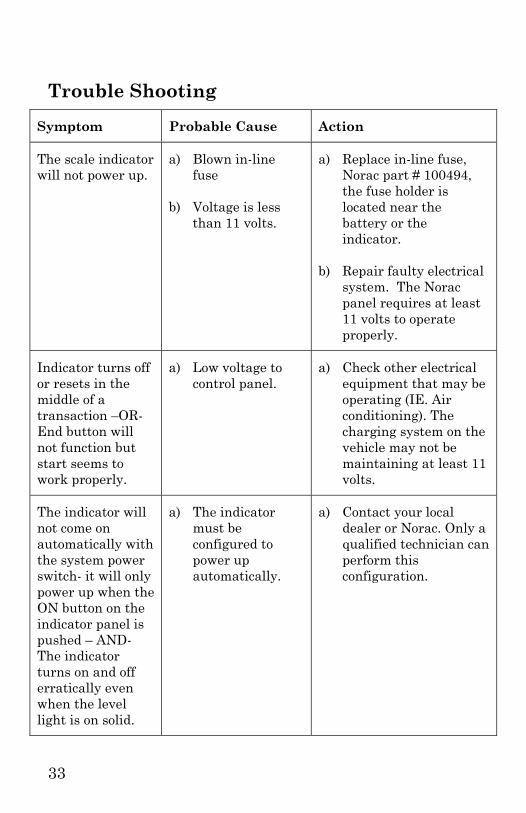
Trouble Shooting
Symptom Probable Cause Action
The scale indicator will not power up.
a) Blown in-line fuse
b) Voltage is less than 11 volts.
a) Replace in-line fuse, Norac part # 100494, the fuse holder is located near the battery or the indicator.
b) Repair faulty electrical system. The Norac panel requires at least 11 volts to operate properly.
Indicator turns off or resets in the middle of a transaction –OR- End button will not function but start seems to work properly.
a) Low voltage to control panel.
a) Check other electrical equipment that may be operating (IE. Air conditioning). The charging system on the vehicle may not be maintaining at least 11 volts.
The indicator will not come on automatically with the system power switch- it will only power up when the ON button on the indicator panel is pushed – AND- The indicator turns on and off erratically even when the level light is on solid.
a) The indicator must be configured to power up automatically.
a) Contact your local dealer or Norac. Only a qualified technician can perform this configuration.
34
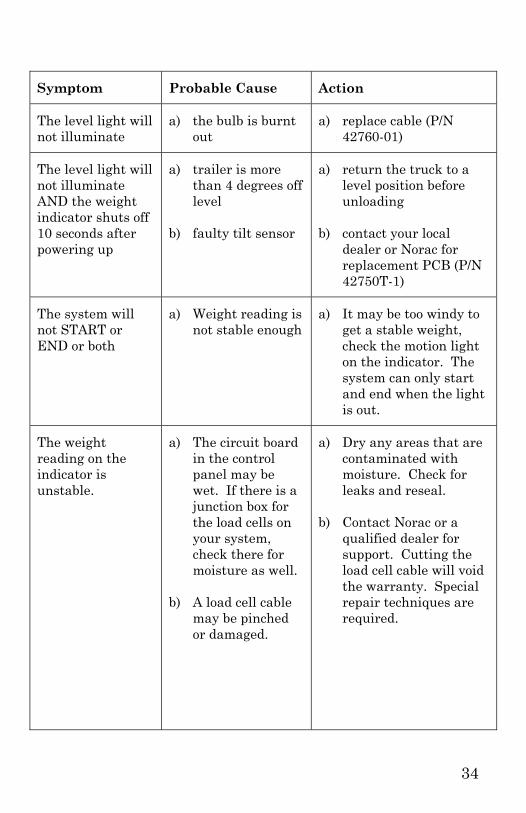
Symptom Probable Cause Action
The level light will not illuminate
a) the bulb is burnt out
a) replace cable (P/N 42760-01)
The level light will not illuminate AND the weight indicator shuts off 10 seconds after powering up
a) trailer is more than 4 degrees off level
b) faulty tilt sensor
a) return the truck to a level position before unloading
b) contact your local dealer or Norac for replacement PCB (P/N 42750T-1)
The system will not START or END or both
a) Weight reading is not stable enough
a) It may be too windy to get a stable weight, check the motion light on the indicator. The system can only start and end when the light is out.
The weight reading on the indicator is unstable.
a) The circuit board in the control panel may be wet. If there is a junction box for the load cells on your system, check there for moisture as well.
b) A load cell cable may be pinched or damaged.
a) Dry any areas that are contaminated with moisture. Check for leaks and reseal.
b) Contact Norac or a qualified dealer for support. Cutting the load cell cable will void the warranty. Special repair techniques are required.

35
Symptom Probable Cause Action
ERR 41 on display Will occur when start is pressed
a) On some systems prior to 1999 when the scales gross weight is zero or negative.
b) On any system if start is pressed when the motion light is on.
a) Make sure the scale will have a positive weight.
b) Wait for scale to settle.
The scale has a positive error when loading or a negative error when unloading
a) Mechanical binding problem on scale
a) Check all hydraulic hoses and conduit, they must be long and loose enough not to exert a force on the scale. Check all load cell covers to see that they are not bent or contacting the lift arm or cylinder.
The scale has a negative error when loading or a positive error when unloading.
a) Moisture is present somewhere in the electrical system.
a) Dry any areas that are contaminated with moisture. Check for leaks and reseal.

36
Symptom Probable Cause Action
Printer is not functioning – nothing is being printed at all
a) Is the release light on the printer flashing? This could indicate a low voltage to the printer
b) The print head may be jammed with paper
c) The print head may be packed with dirt from operating in dusty conditions
a) The Norac system requires at least 11 volts to operate properly. Is the truck running? Your truck may need to be running to supply enough power – OR – the truck may have a faulty electrical system.
b) Remove the print head cover and ribbon. Check for bits of paper stuck in the paper feed mechanism.
c) Remove the print head cover and ribbon. Blow out with air. If the printer is very dirty it may require service by a qualified technician.
The printer is printing unrecognizable characters
a) The power supply on the truck is excessively noisy.
a) Contact Norac, an in-line power filter may be necessary.
The printing on the ticket is faint or hard to read.
a) The printer’s ink ribbon may need to be replaced.
b) The printer head may be damaged.
a) Replace ribbon, Norac part # 82282-1
b) Requires service by a qualified technician.

37
Symptom Probable Cause Action
Cannot load the system to full capacity without getting “eeeeee” on the display
a) Dead load has been added to the scale since it was calibrated
a) Contact your local scale dealer
Display reads “eeeee” or “uuuuu”
a) A load cell has become disconnected.
a) Inspect for damage and consult you local scale dealer.
IF YOU SUSPECT THERE IS A PROBLEM INSIDE THE NORAC CONTROL PANEL THAT REQUIRES THE WEIGHTS AND MEASURES SEAL TO BE BROKEN YOU MUST CONTACT NORAC PRIOR TO BREAKING THE SEAL, OR HAVE A QUALIFIED SCALE DEALER BREAK THE SEAL.
BREAKING THE SEAL MAY VIOLATE THE WEIGHTS AND MEASURES APPROVAL OF THE SCALE.
Notes:
Size / Model # ___________________________
Serial # _________________________________
Date Purchased _________________________
Unit ID # _______________________________

38
NORAC Statement of Limited Warranty
All NORAC scale products are warranted against defects due to faulty material or workmanship for a period of one (1) year. NORAC Systems International Inc. extends this warranty only to the original purchaser or original user. In the event a defect develops during the warranty period, NORAC will repair or replace the unit with a new or reconditioned model of equivalent quality. In order to obtain performance of any obligation of NORAC Systems International Inc. under the warranty, the original purchaser or original user must return the defective unit, with a written description of the complaint, freight prepaid to the manufacturer or a designated service depot. In the event of replacement with a new or reconditioned model, the replacement unit will continue the warranty period of the original unit. NORAC Systems International shall not be liable for loss of use of the unit or the incidental or consequential damages, expenses, or economic loss, or for any claim or claims for such damage, expenses or economic loss. Any questions with respect to the warranty should be taken up with NORAC Systems International Inc. 306-664-6711.