potential for low-temperature capture technologies in
TRANSCRIPT

Potential for low-temperature capture technologies in different
CCS applications
2011-06-16David Berstad, Petter Nekså, Rahul Anantharaman
[email protected] Energy Research
1

Presentation outline
► Introduction and definitions►Differences in capture conditions within different CCS
applications►Review of examples on application of low-temperature
concepts for some of the capture conditions Oxy-combustion: Flue gas separation Pre-combustion: IGCC syngas separation Post-combustion: CO2 antisublimation from flue gas
►Discussion and concluding remarks
2

Cryogenic often used instead of low-temperature in literature, sometimes with a negative notion“Use of cryogenic processes – is only worth considering where there is a high concentration of CO2 in the flue gas, as could be achieved in future IGCC designs. Cryogenic processes have the advantage of producing liquid CO2 ready for transportation by pipeline”Riemer P. Greenhouse gas mitigation technologies, an overview of the CO2 capture, storage and future activities of the IEA Greenhouse Gas R&D programme, 37(6–8), 665–70 (1996).
“Cryogenic separation needs too much energy and appears to be too expensive […] In the end, only physical and chemical (or mixed) absorption methods seem suitable for large power plants…”Kanniche, M. and C. Bouallou. CO2 capture study in advanced integrated gasification combined cycle. Applied Thermal Engineering, 27(16), 2693–2702 (2007).
“The basic advantage of cryogenic processes is that, provided the CO2 feed is properly conditioned, high recovery of CO2 and other feed constituents is possible. This may also facilitate the final use or sequestering of CO2. However, cryogenic processes are inherently energy intensive.”Meisen, A, Shuai X. Research and development issues in CO2 capture. Energy Conversion and Management, 38(1), S37–S42 (1997).
This, at least, does not apply to all capture conditions!And, do we actually enter cryogenic temperatures?
3

Cryogenic vs. low-temperature, definitions and terminologyGenerally inconsistent use of the term ‘cryogenic’ in literatureCryogenic temperatures:
Common scientific definition: Temperatures below -153°C (120 K) IIR Int Dict
Important to distinguish between ‘cryogenic’ and ’low-temperature’ Low-temperature CO2 capture:
Temperatures below 0°C Liquid phase separation, temp above the CO2 triple point temp (≥ -56°C)
Applied to flue gas and synthesis gas above CO2 triple point pressure (5.2 bar) Implies condensation of CO2 without the use of circulating solvents/chemicals Separation of CO2-rich liquid phase from non-condensables (N2, O2, Ar, H2 etc.) CO2 in liquid phase, pressurisation by pumping instead of multi-stage gas
compression Solid phase sep, below the CO2 triple p. temp (< -56°C) but above -120°C
Implies antisublimation / freeze-out of CO2 as solids from non-condensables Can be applied to flue gas at pressures below CO2 triple point pressure (5.2 bar)
4
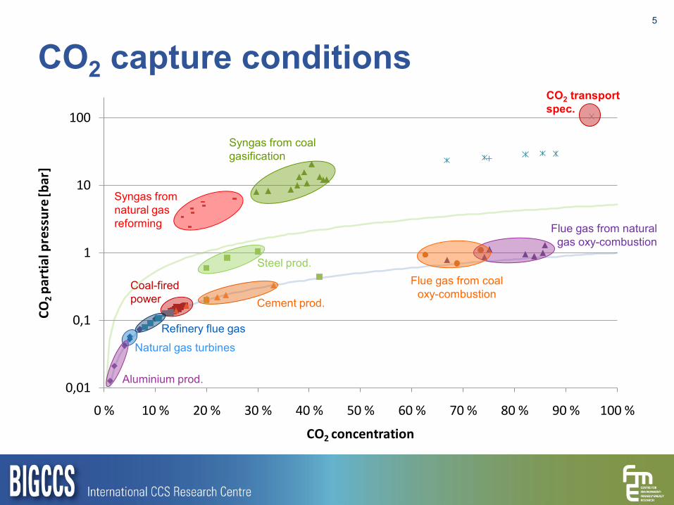
CO2 capture conditions5
0,01
0,1
1
10
100
0 % 10 % 20 % 30 % 40 % 50 % 60 % 70 % 80 % 90 % 100 %
CO2
part
ial p
ress
ure
[bar
]
CO2 concentration
Syngas from coal gasification
Syngas from natural gas reforming Flue gas from natural
gas oxy-combustion
Flue gas from coal oxy-combustion
Steel prod.
Cement prod.
Aluminium prod.
Natural gas turbines
Coal-fired power
Refinery flue gas
CO2 transport spec.

CO2 capture conditions6
0,01
0,1
1
10
100
0 % 10 % 20 % 30 % 40 % 50 % 60 % 70 % 80 % 90 % 100 %
CO2
part
ial p
ress
ure
[bar
]
CO2 concentration
Syngas from coal gasification
Syngas from natural gas reforming Flue gas from natural
gas oxy-combustion
Flue gas from coal oxy-combustion
Steel prod.
Cement prod.
Aluminium prod.
Natural gas turbines
Coal-fired power
Refinery flue gas
CO2 transport spec.
5.2 bar

CO2 capture conditions7
0,01
0,1
1
10
100
0 % 10 % 20 % 30 % 40 % 50 % 60 % 70 % 80 % 90 % 100 %
CO2
part
ial p
ress
ure
[bar
]
CO2 concentration
Syngas from coal gasification
Syngas from natural gas reforming Flue gas from natural
gas oxy-combustion
Flue gas from coal oxy-combustion
Steel prod.
Cement prod.
Aluminium prod.
Natural gas turbines
Coal-fired power
Refinery flue gas
CO2 transport spec.
Compression
Oxy-derived flue gases after compression
5.2 bar

Oxy-combustion CO2 capture8
Compression, conditioning and water removal
Cooling (process-to-process and/or
auxiliary refrigeration)
Single or multiple flash separation/
distillation
Flue gasCompressed and
dried flue gasPartially condensed
flue gas
Volatiles (N2, O2, Ar, …)Purge
Captured CO2
Liquid pumping or gas compression
400
450
500
550
600
650
60 % 65 % 70 % 75 % 80 % 85 % 90 %
Capt
ure
wor
k [k
J/kg
CO2]
Flue gas CO2 concentration
Pipitone and Bolland (2009)
Amann (2009)
Berstad, Nekså, Anantharaman (2011)
80
82
84
86
88
90
92
94
96
98
60 % 65 % 70 % 75 % 80 % 85 % 90 %
CO2
capt
ure
ratio
[%]
Flue gas CO2 concentration
Pipitone and Bolland (2009)
Amann (2009)
Berstad, Nekså, Anantharaman (2011)
Amann J, Kanniche M, Bouallou C. Natural gas combined cycle power plant modified into an O2/CO2 cycle for CO2 capture, Energy Conversion and Management 50(3), 510–521 (2009).Pipitone G, Bolland O. Power generation with CO2 capture: Technology for CO2 purification, Int. Journal of GHG Control. 3(5): 528–534 (2009).

Oxy-combustion CO2 capture9
Compression, conditioning and water removal
Cooling (process-to-process and/or
auxiliary refrigeration)
Single or multiple flash separation/
distillation
Flue gasCompressed and
dried flue gasPartially condensed
flue gas
Volatiles (N2, O2, Ar, …)Purge
Captured CO2
Liquid pumping or gas compression
400
450
500
550
600
650
60 % 65 % 70 % 75 % 80 % 85 % 90 %
Capt
ure
wor
k [k
J/kg
CO2]
Flue gas CO2 concentration
Pipitone and Bolland (2009)
Amann (2009)
Berstad, Nekså, Anantharaman (2011)
80
82
84
86
88
90
92
94
96
98
60 % 65 % 70 % 75 % 80 % 85 % 90 %
CO2
capt
ure
ratio
[%]
Flue gas CO2 concentration
Pipitone and Bolland (2009)
Amann (2009)
Berstad, Nekså, Anantharaman (2011)
Amann J, Kanniche M, Bouallou C. Natural gas combined cycle power plant modified into an O2/CO2 cycle for CO2 capture, Energy Conversion and Management 50(3), 510–521 (2009).Pipitone G, Bolland O. Power generation with CO2 capture: Technology for CO2 purification, Int. Journal of GHG Control. 3(5): 528–534 (2009).

Oxy-combustion CO2 capture10
Compression, conditioning and water removal
Cooling (process-to-process and/or
auxiliary refrigeration)
Single or multiple flash separation/
distillation
Flue gasCompressed and
dried flue gasPartially condensed
flue gas
Volatiles (N2, O2, Ar, …)Purge
Captured CO2
Liquid pumping or gas compression
400
450
500
550
600
650
60 % 65 % 70 % 75 % 80 % 85 % 90 %
Capt
ure
wor
k [k
J/kg
CO2]
Flue gas CO2 concentration
Pipitone and Bolland (2009)
Amann (2009)
Berstad, Nekså, Anantharaman (2011)
80
82
84
86
88
90
92
94
96
98
60 % 65 % 70 % 75 % 80 % 85 % 90 %
CO2
capt
ure
ratio
[%]
Flue gas CO2 concentration
Pipitone and Bolland (2009)
Amann (2009)
Berstad, Nekså, Anantharaman (2011)
-56°C -54°C
-50°C
Amann J, Kanniche M, Bouallou C. Natural gas combined cycle power plant modified into an O2/CO2 cycle for CO2 capture, Energy Conversion and Management 50(3), 510–521 (2009).Pipitone G, Bolland O. Power generation with CO2 capture: Technology for CO2 purification, Int. Journal of GHG Control. 3(5): 528–534 (2009).

Syngas from coal gasification (IGCC)11
Berstad D, Nekså P, Anantharaman R. CO2 capture from IGCC by low-temperature syngas separation and partial condensation of CO2. TCCS-6 (2011)
Isentropic eff. syngas compressor % 82Isentropic eff. propane/ethane compressors % 82Isentropic eff. recycle compressor % 80Isentropic eff. power recovery expander % 85Eff. liquid CO2 pump % 80ΔP per heat exchanger bar 0.2ΔP inter- and after-coolers bar 0.5Minimum approach T in heat exchangers C 3ΔT in propane–ethane cascade heat exchanger C 5
250
275
300
325
350
60 %
65 %
70 %
75 %
80 %
85 %
90 %
30 40 50 60 70 80 90 100 110 120
Capt
ure
wor
k [k
J/kg
CO2]
CO2
capt
ure
ratio
Syngas pressure [bar]
CO2 capture ratio
Capture work
CO2 pump
CO2 (110 bar)
Shifted syngas(54% H2, 38% CO2)
Power recovery expanderH2-rich fuel to
gas turbine
Recycle
CO2 purification
Phase separation
Auxiliary refrigeration (Propane)
Auxiliary refrigeration (Ethane) H2-rich phase
CO2-rich phase
Should be competitive with physical solvents
35 bar

Post-combustion capture by antisublimation (Clodic et al., 2005)
12
Clodic D et al. CO2 capture by anti-sublimation .Thermo-economic process evaluation. 4th Annual Conference on Carbon Capture & Sequestration, May 2–5, 2005, Alexandria (VA), USA.

13
Clodic D et al. CO2 capture by anti-sublimation .Thermo-economic process evaluation. 4th Annual Conference on Carbon Capture & Sequestration, May 2–5, 2005, Alexandria (VA), USA.
Highly dependent on COP of refrigeration cycles
Post-combustion capture by antisublimation (Clodic et al., 2005)

Summary14
0,01
0,1
1
10
100
0 % 10 % 20 % 30 % 40 % 50 % 60 % 70 % 80 % 90 % 100 %
CO2
part
ial p
ress
ure
[bar
]
CO2 concentration
Syngas from coal gasification
Syngas from natural gas reforming Flue gas from natural
gas oxy-combustion
Flue gas from coal oxy-combustion
Steel prod.
Cement prod.
Aluminium prod.
Natural gas turbines
Coal-fired power
Refinery flue gas
CO2 transport spec.
Post-combustion antisublimation
Pre-combustion syngas separation
Oxy-combustion flue gas separation

Conclusions►Substantial difference in CO2 capture conditions with
respect to concentrations and pressure.►Low-temperature capture technologies can in principle be
applied for most of these conditions►For certain applications, conceptual studies indicate
competitive energy performance►To obtain a complete benchmarking between low-
temperature and baseline technologies, global simulations, with equalised boundary conditions and detail levels, must be performed
►Finally, techno-economic comparisons based on realistic cost data for full-scale processes must be carried out
15

Acknowledgements
This publication has been produced with support from the BIGCCS Centre, performed under the Norwegian research program Centres for Environment-friendly Energy Research (FME). The authors acknowledge the following industrial partners for their contributions: Aker Solutions, ConocoPhilips, Det Norske Veritas, Gassco, Hydro, Shell, Statkraft, Statoil, TOTAL, GDF SUEZ and the Research Council of Norway (193816/S60).
16